

Page 1
MONITOR UNIT MU-201CE/MU-231CE
OPERATOR'S MANUAL
This manual describes only the key operations of the monit or unit MU-210CE/MU-231CE.
For other details, refer to the installation manual and operator’s manual of the ECDIS/radar.
1. Overview
When the monitor unit MU-201CE or MU-231CE is connected to a r adar/ECDIS
with an RS-232C cable, the keys on the panel are locked, so independent
operation of the keys is not possible. Brilliance is controlled from ECDIS/radar.
Key function under lock condition
Simultaneous pressing of Lock and Menu keys: Opens/closes the menu.
Simultaneous pressing of Lock and Input keys: Choose an input signal.
Simultaneous pressing of Lock and
turn it off, press more than five seconds.
The keys are unlocked with menu operation. See “Keypad lock” on page 6. The
key functions under unlocked condition are as follows.
+ and -: Adjusts the screen brilliance when no menu di splayed. With menu
Input: Chooses input signal to display (when no menu is displayed).
Menu: Opens or closes menu.
Enter: Confirms menu setting.
key: Turns the power on or off. To turn the power off, press it more than
five seconds.
displayed, these choose an item from the menu.
keys: Turns the power on or off. To
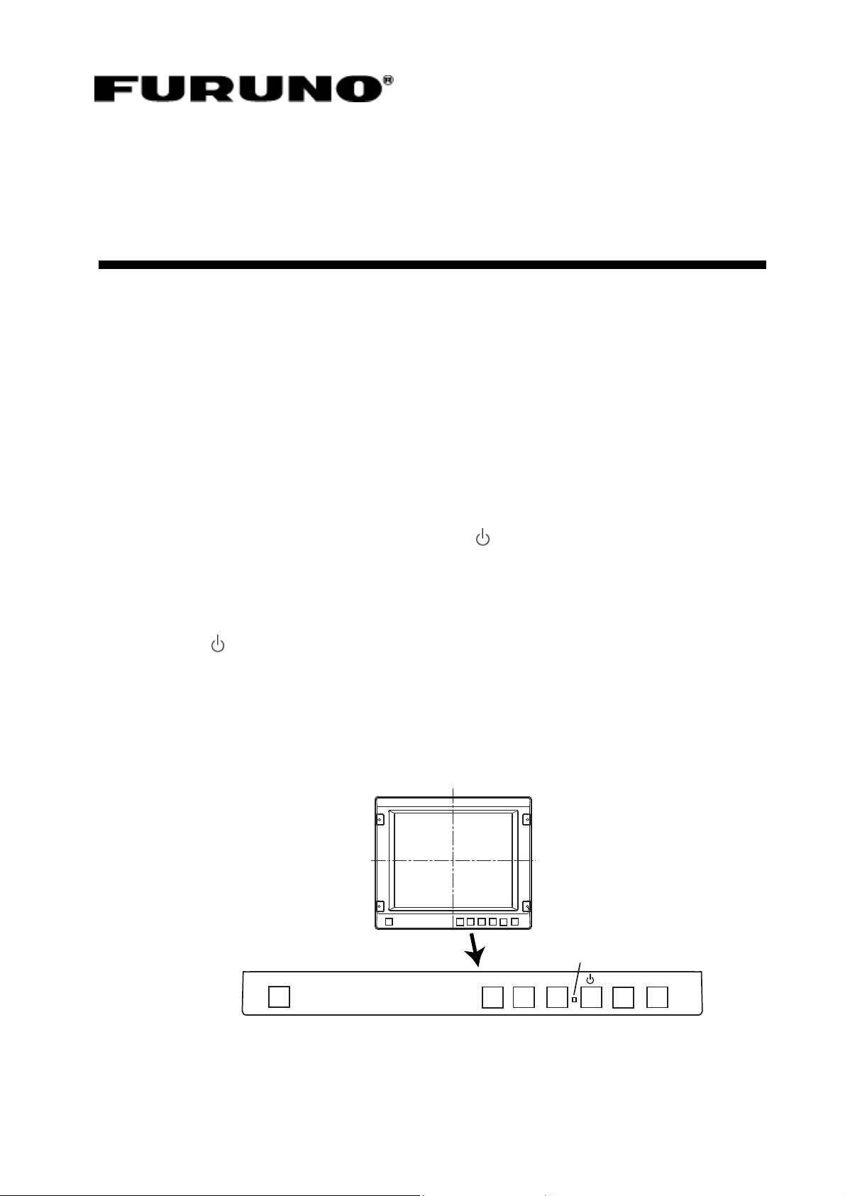
Lock
Operation Panel
LED lamp: lights when the monitor unit is turned on.
Menu Enter Input - +
1
LED
Page 2
2. Menu Operation
1. Press the Menu key to open the main menu.
The chosen menu item is circumscribed with a blue rectangle and its sub-menu is
displayed below the main menu.
2. Press the + or – key to choose a menu and press the Enter key.
3. Press the + or – key to choose a sub-menu item and press the Enter key.
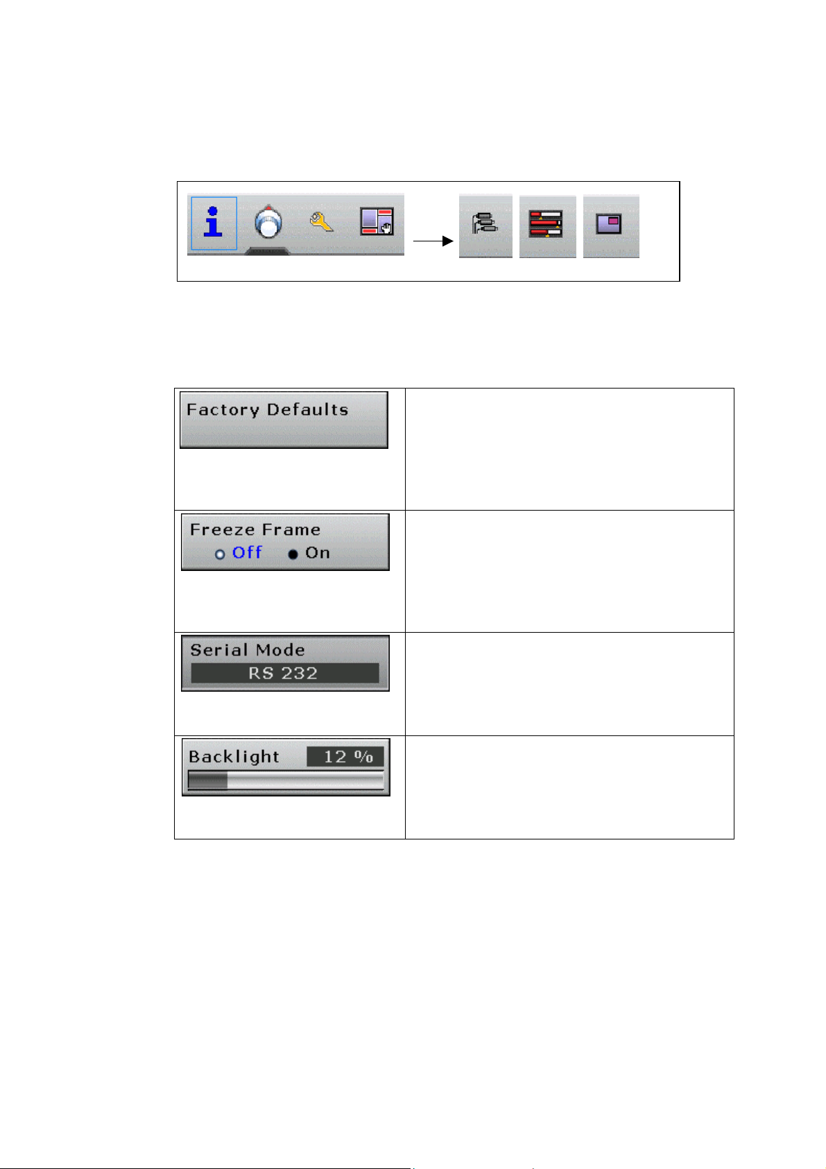
There are four kinds of items available in each sub-menu. A brief explanation
of each follows.
Scroll
Keys
They just need to be confirmed for
selection in order to activate the
corresponding function. The key in this
example will perform factory defaults
restore as soon as selected.
On/off settings
They just need to be confirmed for
selection in order to toggle between the on
and off state of the option. Th e setting in
this example will toggle between normal
mode and freeze frame mode as selected.
Item lists
Once activated, these items allow the user
to select a given mode of operation among
the ones available by pressing the + or –
key and then Enter key.
Gauges
Once activated, these items allow the user
to change the setting at will between zero
and one hundred percent by pressing the +
or - key and then Enter key.
4. To change other item in the sub-menu, return to step 3.
5. Press the Menu key to conclude sub-menu setting.
To change the setting of another menu, go to step 2.
6. Press the Menu key to close the main menu.
2
Page 3

3. Menu Functions
This section of the manual describes each function of each menu in detail. Each
paragraph represents a given menu. On the left, an image shows all items that
can appear in that menu, while on the right an item by item description is given,
in the same order as shown at the screen. Each paragraph is named after the
menu it represents, and the icon for that menu is shown n ear the menu name.
Please note that the numeric values shown in the boxes are meaningless an d do
not represent values that are meant to be valid. When using the equipment, the
GUI will allow or disallow some values to be entered depending on the current
conditions.
Also note that no item is shown as selected. Although every possible item is
shown in the images, not all of them may be shown on the equipment's GUI
when using it, because each item is shown only if certain conditions are met.
Information menu
Input resolution
This box shows details of the signal that is currently
displayed. The values shown are: horizontal
resolution (pixels), vertical resolution (pixels) and
vertical refresh frequency (Hz). The content of this
box cannot be changed.
Detected mode
The value displayed in this box cannot be changed
and informs the user about the numeric identifier
associated with the signal displayed. This is useful
to establish if two given input signals have identical
parameters or not.
Firmware version
This box cannot be selected, and its value cannot
be changed. It informs the user about the version of
the firmware programmed into the monitor.
3
Page 4

Main window image settings
Backlight
Adjust the intensity of the backlight of the display.
This is automatically adjusted by radar/ECDIS.
LED level
Adjust the intensity of the LED on the front panel.
Brightness
Make the picture brighter or darker.
Contrast
View dark details on dark backgrounds. This setting
should be adjusted after the brightness so as to
make the white color as bright as possible without
interfering with grays.
Sharpness
Make the picture more or less detailed. More
detailed pictures are clearer but introduce some
picture noise, while less detailed pictures are
slightly blurred but have reduced noise.
Gamma correction
Choose the chromatic response of the display. In
particular, "linear" should be used with flat panel
LCD displays.
Color temp
Make the picture warmer or colder by changing the
white temperature. The value is expressed in
Kelvin.
Red, green and blue temp
Change the quantity of red, green and blue that the
image contains.
Scaling mode
Choose how to view signals with an aspect ratio
different from that of the display. The "one to one"
mode displays the signal without scaling. The "fill
all" mode stretches the picture so the whole screen
gets filled; this may make the picture squashed or
stretched. The "fill to aspect ratio" mode makes the
input signal fill the screen but without squashing or
stretching, maintaining the aspect ratio of the input
signal. Use the default setting.
After installation or execution of Factory defaults (page 6), set the brightness,
contrast, and red/green/blue temperatures as follows.
MU-201CE
MU-231CE
Brightness 43%
Contrast 60%
Red temp 50%
Green temp 67%
Blue temp 65%
Brightness 43%
Contrast 55%
Red temp 50%
Green temp 67%
Blue temp 65%
4
Page 5

General monitor settings
Freeze frame
This function, when activated, freezes the image
on the screen, disregarding the input signal until
deactivated.
Source information
This setting allows the user to disable the source
information that appears on the upper left hand
corner each time a source is detected or Input
key is pressed. Always use On state.
OSD timeout
Choose how much time the GUI will remain
displayed on the screen when no control is being
used. When the user is not touching the monitor
controls, this timer will, after the selected period of
time, remove the GUI from the screen.
Logo timeout
Choose how much time the logo will remain on
the screen when the display is powered. The
"Disabled" option will make the display skip the
logo display at start up.
Monitor timeout
Choose how much time the monitor will remain
powered when the user is not touching its
controls. The "Disabled" setting disables this
feature. After the selected time has passed and
the user has not touched the monitor controls, it
will automatically power off. Set to "Disabled" for
radar/ECDIS.
Monitor address
Choose to which address the monitor should
respond when ECDIS commands are detected
over the serial link.
Serial mode
Choose what kind of serial bus is connected to
the monitor. Use the default setting (RS 232).
Monitor to monitor
Choose whether the display initiates an ECDIS
transmission towards the other displays
connected to it when the user tries to adjust the
backlight level. In "Slave" mode, the monitor
never initiates ECDIS transmissions on its own. In
"Master" mode, the monitor issues an ECDIS
command over the serial link each time the
backlight is changed. This function is only
available if serial mode is set to 422 or 485.
5
Page 6

User preferences
Keypad lock
Set whether the keypad is locked or not. When
locked, the keypad does not answer to user
commands, unless the LOCK key is pressed
together with a desired key. If the monitor is
connected to radar/ECDIS with an RS-232C
cable, Off returns to On after turning the power off
and then on.
Serial protocol
Choose how the equipment will respond to
ECDIS commands. In Standard ECDIS mode, the
equipment will be compliant with the ECDIS
specification, while in ISIC ECDIS mode the
values are transmitted in decimal representation
and are scaled to a percentage ran ge.
OSD Position
Choose if the On Screen Display is shown on the
right or left side of the monitor.
Factory defaults
This function provides a reset of the monitor
to the factory defaults. By activating this
function, all settings made by the user will be
lost and the monitor will be brought back to
known operating conditions.
Setup selection
This setting allows the user to select which
user slot to handle with the Save monitor
setup and Recall monitor setup keys.
Save monitor setup
This function allows the user to save all
important current settings to a memory for
later recall. There are three slots available;
which one is used to store the settings
depends on the Setup selection menu item.
Saving settings in a slot that contains
previous settings will overwrite the old
settings to store the new ones.
Recall monitor setup
This function allows the user to recall the
settings stored with the Save monitor setup
push key. Which setting is recalled depends
on the Setup selection menu item.
6
Page 7

Input selection
Source
Choose the input source for the main
screen. As soon as a change is made
here, the corresponding input will be
selected and activated for display on the
main screen. To change the active source
for the PIP window, use the PIP menu.
Source enable items
These menu items allow the user to
disable some sources. When a source is
disabled (set to Off), it cannot be selected
by means of the Input key on the
monitor's keypad.
7
Page 8

Main screen acquisition settings
This menu is available when PIP is set to ON.
(See next page.)
Mode selection
Choose a memory slot in which to store
display parameters for a given input signal.
Once stored in a memory slot, the settings for
the current input signal can be modified at will,
and they will be reapplied when the same
source is detected again.
Mode details
This box shows what's inside the memory slot
selected with the Mode selection setting.
Load current mode
This stores the settings detected by the image
processor for the current signal in the memory
slot selected with the Mode selection setting.
Once the detected parameters have been
stored in memory, they can be edited by the
user with the controls described below.
Clear
Press this key to delete the contents of the
selected memory slot. Once the content of a
given slot has been deleted, it is lost and
cannot be retrieved.
H. total
Adjust the frequency of the clock signal used
to drive the analog to digital converter that
samples the input signal.
Phase
Adjust the phase of the clock used to drive the
analog to digital converter that samples the
input signal.
H. res. and V. res.
By means of this setting, the user is able to
force the image processor into detecting the
current signal with a given horizontal or
vertical resolution.
H. pos. and V. pos
These two settings allow the user to move the
input signal around on the main screen, so it is
displayed correctly in its entirety.
8
 Loading...