

Page 1

OPERATOR'S MANUAL
COLOR SCANNING SONAR
Model
FSV-85
www.furuno.com
Page 2

The paper used in this manual
9-52 Ashihara-cho,
A:MAR
2011
.
B1:FEB.07, 2013
Pub. No.
(
)
*00017433911*
Nishinomiya, 662-8580, JAPAN
is elemental chlorine free.
・FURUNO Authorized Distributor/Dealer
All rights reserved.
ETMI
FSV-85
Printed in Japan
OME-13350-B1
*00017433911*
* 0 0 0 1 7 4 3 3 9 1 1 *
Page 3
IMPORTANT NOTICES
General
• This manual has been authored with simplified grammar, to meet the needs of international users.
• The operator of this equipment must read and follow the descriptions in this manual. Wrong operation or maintenance can cancel the warranty or cause injury.
• Do not copy any part of this manual without written permission from FURUNO.
• If this manual is lost or worn, contact your dealer about replacement.
• The contents of this manual and equipment specifications can change without notice.
• The example screens (or illustrations) shown in this manual can be different from the screens
you see on your display. The screens you see depend on your system configuration and equipment settings.
• Save this manual for future reference.
• Any modification of the equipment (including software) by persons not authorized by FURUNO
will cancel the warranty.
• All brand and product names are trademarks, registered trademarks or service marks of their
respective holders.
How to discard this product
Discard this product according to local regulations for the disposal of industrial waste. For disposal
in the USA, see the homepage of the Electronics Industries Alliance (http://www.eiae.org/) for the
correct method of disposal.
How to discard a used battery
Some FURUNO products have a battery(ies). To see if your product has a battery, see the chapter
on Maintenance. Follow the instructions below if a battery is used. Tape the + and - terminals of
battery before disposal to prevent fire, heat generation caused by short circuit.
In the European Union
The crossed-out trash can symbol indicates that all types of batteries
must not be discarded in standard trash, or at a trash site. Take the
used batteries to a battery collection site according to your national
legislation and the Batteries Directive 2006/66/EU.
In the USA
The Mobius loop symbol (three chasing arrows) indicates that Ni-Cd
and lead-acid rechargeable batteries must be recycled. Take the used
batteries to a battery collection site according to local laws.
In the other countries
Cd
PbNi-Cd
There are no international standards for the battery recycle symbol. The number of symbols can
increase when the other countries make their own recycle symbols in the future.
i
Page 4
SAFETY INSTRUCTIONS
The operator of this equipment must read the safety instructions before attempting to operate
the equipment.
Indicates a hazardous situation which, if not avoided, will result in
DANGER
WARNING
CAUTION
death or serious injury.
Indicates a potentially hazardous situation which, if not avoided,
could result in death or serious injury.
Indicates a potentially hazardous situation which, if not avoided,
may result in minor or moderate injury.
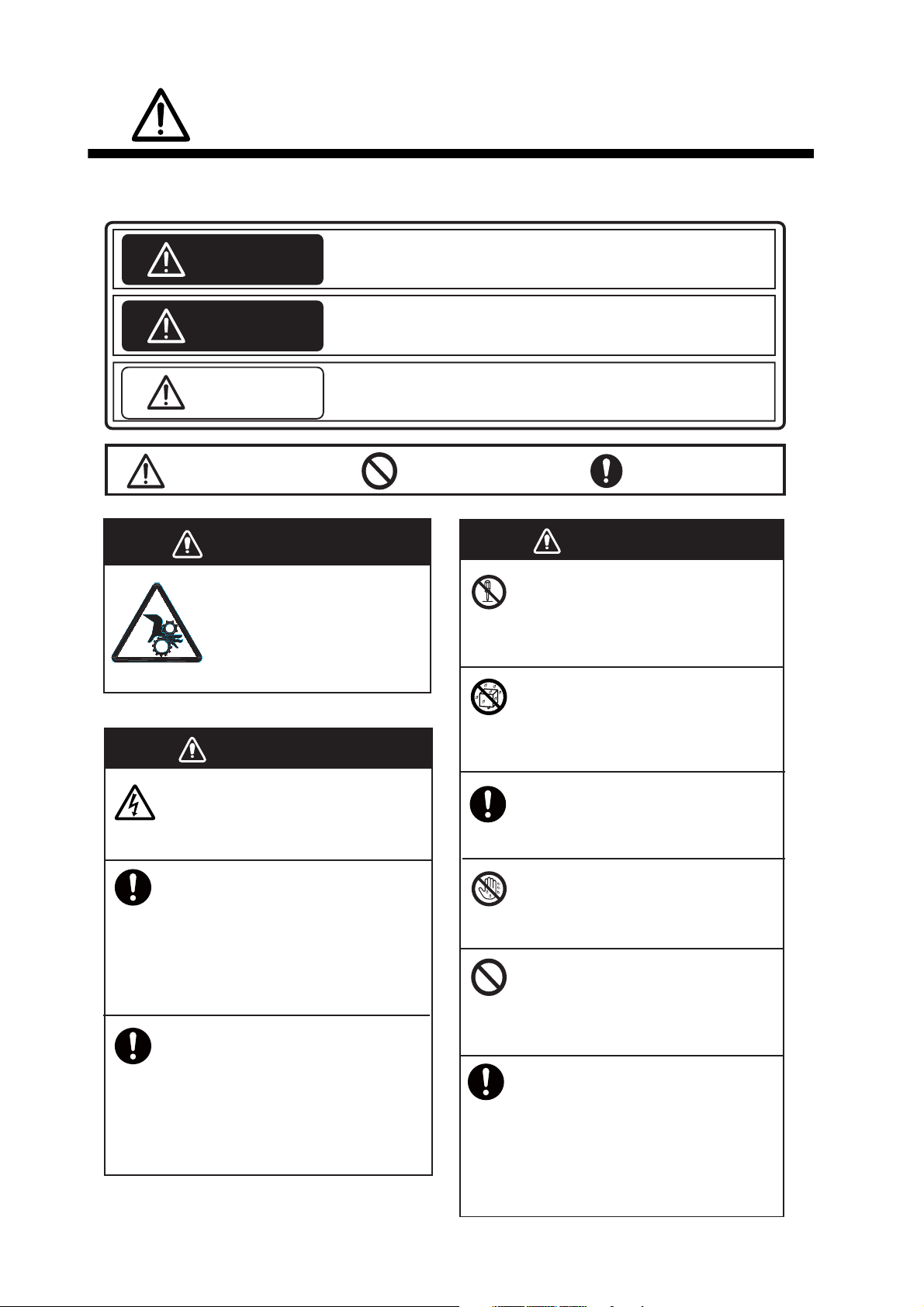
Warning, Caution
Prohibitive Action
DANGER
Keep away from raise/lower
shaft in hull unit when it is
moving.
Gears in hull unit will cause
serious injury.
WARNING
Do not open the equipment.
Only qualified personnel should work
inside the equipment.
Immediately turn off the power at the
switchboard if water leaks into the
equipment or something is dropped
into the equipment.
Mandatory Action
WARNING
Do not disassemble or modify the
equipment.
Fire, electrical shock or serious injury can
result.
Do not install the equipment where it
may be subject to rain or water splash.
Fire or electrical shock can result if water
leaks in the equipment.
Use the proper fuse.
Use of a wrong fuse can result in damage
to the equipment or cause fire.
Do not operate the equipment with
wet hands.
Electrical shock may result.
Continued use of the equipment can cause
fire or electrical shock. Contact a FURUNO
agent for service.
Immediately turn off the power at the
switchboard if the equipment is emitting
smoke or fire.
Continued use of the equipment can cause
fire or electrical shock. Contact a FURUNO
agent for service.
Do not place liquid-filled containers on
the top of the equipment.
Fire or electrical shock can result if a liquid
spills into the equipment.
Turn off the power immediately
if you feel the equipment is behaving
abnormally.
Turn off the power at the switchboard if
the equipment becomes abnormally warm
or is emitting odd noises. Contact a
FURUNO dealer or agent for advice.
ii
Page 5
SAFETY INSTRUCTIONS
CAUTION
CAUTION
CAUTION
Maximum speed while the transducer is
projected and being raised or lowered
is as below, to prevent damage to the
transducer.
Projected
Max. 18 kn
Replace anticorrosion zinc plate yearly.
Corrosion between the main shaft and
transducer may result if not replaced, allowing
water leakage and/or loss of transducer.
Raising/
Lowering
Max. 15 kn
CAUTION
Observe the following precautions when
using industrial use lubricant.
Precautions
Keep lubricant away from eyes. Wear protective
goggles when working with the lubricant.
The lubricant can cause inflammation of the eyes.
Do not touch the lubricant. Wear protective gloves
when working with the lubricant. The lubricant can
cause inflammation of the skin.
Do not ingest the lubricant. Diarrhea and vomiting
may result.
Keep the lubricant out of reach of children.
Emergency procedures
If the lubricant enters eyes, flush with clean water
about 15 minutes. Consult a physician.
If the lubricant contacts skin, flush area with clean
water.
If the lubricant is ingested, see a physician
immediately.
Disposal of lubricant and its container
Dispose of the lubricant and its container in accordance with local regulations. If you are unclear about
the disposal procedure, contact a FURUNO agent or
dealer for advice.
WARNING LABELS
Warning labels are attached to the units of the system. Do not remove the labels.
If a label is missing or damaged, contact a FURUNO agent or dealer about replacement
WARNING
Moving main shaft can pinch
and cut.
Keep hands dear while operating.
Lockout power before servicing.
⼊㩷㩷๔
േ䉲䊞䊐䊃ㇱಽ䈲ᚻ䉕䈲䈘䉃
ᕟ䉏䈅䉍䇯
Ⓙേ䈲ᚻ䉕ㄭ䈨䈔䈭䈇䈖䈫䇯
䉰䊷䊎䉴䉕ⴕ䈉೨䈲㔚Ḯ䉕ಾ䉎䈖䈫䇯
Name: Finger Warning Label
Type: 06-021-4015
Code No.: 100-281-590-10
DANGER
Electrical shock hazard.
Do not remove cover.
No user-serviceable parts inside.
Turn off power before servicing.
And wait until chargelamp (green)
goes off and then remove cover.
ෂ㩷㩷㒾
ᗵ㔚䈱ᕟ䉏䈅䉍䇯
䉰䊷䊎䉴䊙䊮એᄖ䈱ᣇ䈲䇮䉦䊋䊷䉕㐿䈔䈭䈇䈪
䈒䈣䈘䈇䇯㩷ౝㇱ䈮䈲㜞ㇱຠ䈏ᢙᄙ䈒䈅䉍䇮
৻䈘䉒䉎䈫ෂ㒾䈪䈜䇯
䉰䊷䊎䉴䊙䊮䈏䉦䊋䊷䉕㐿䈔䉎႐ว䈲䇮㔚Ḯ䉕
㪦㪝㪝䈚䈢ᓟ䇮䌃䌈䌁䌒䌇䌅䊤䊮䊒䋨✛䋩䈏ᶖἮ
䈚䈩䈇䉎䈖䈫䉕⏕䈚䈩䈎䉌㐿䈔䈩䈒䈣䈘䈇䇯
WARNING
To avoid electrical shock, do not
remove cover. No user-serviceable
parts inside.
⼊䇭๔
ᗵ㔚䈱ᕟ䉏䈅䉍䇯
䉰䊷䊎䉴䊙䊮એᄖ䈱ᣇ䈲䉦䊋䊷䉕㐿䈔
䈭䈇䈪䈘䈇䇯ౝㇱ䈮䈲㜞㔚ㇱಽ䈏
ᢙᄙ䈒䈅䉍䇮৻䈘䉒䉎䈫ෂ㒾䈪䈜䇯
Name: Warning Label (1)
Type: 86-003-1011-3
Code No.: 100-236-233-10
Name: Warning Label
Type: 10-079-6144
Code No.: 100-310-880-10
iii
Page 6

TABLE OF CONTENTS
FOREWORD ................................................................................................................... ix
SYSTEM CONFIGURATION ...........................................................................................x
1. OPERATIONAL OVERVIEW .................................................................................1-1
1.1 Control Description.....................................................................................................1-1
1.1.1 Control unit..................................................................................................... 1-1
1.1.2 Sub control unit (option)................................................................................. 1-2
1.1.3 Remote controller (option).............................................................................. 1-3
1.2 Turning the Power On/Off ..........................................................................................1-4
1.3 Lowering, Raising the Transducer ............................................................................. 1-4
1.3.1 Lowering the transducer................................................................................. 1-5
1.3.2 Raising the transducer ................................................................................... 1-5
1.4 Screen Brilliance, Panel Dimmer ............................................................................... 1-5
1.4.1 Screen brilliance............................................................................................. 1-5
1.4.2 Panel dimmer.................................................................................................1-5
1.5 Display Mode, Display Division .................................................................................. 1-6
1.5.1 How to select a display mode ........................................................................1-8
1.5.2 Display mode pictures....................................................................................1-8
1.6 How to Adjust the Gain ............................................................................................ 1-11
1.7 How to Use the Menu...............................................................................................1-12
2. HORIZONTAL MODE ............................................................................................2-1
2.1 Basic Operating Procedure ........................................................................................ 2-1
2.2 Indications and Markers ............................................................................................. 2-2
2.2.1 Horizontal mode, full-screen display .............................................................. 2-2
2.2.2 Horizontal2 mode........................................................................................... 2-3
2.3 Display Range............................................................................................................2-4
2.4 Tilt Angle .................................................................................................................... 2-5
2.4.1 How to set the tilt angle..................................................................................2-5
2.4.2 Automatic tilt................................................................................................... 2-5
2.4.3 Relation between bottom echo and tilt angle................................................. 2-7
2.4.4 Tilt angle for surface fish................................................................................2-8
2.4.5 Suitable tilt angle............................................................................................2-8
2.5 How to Measure Range and Bearing to a Target.......................................................2-9
2.6 How to Eliminate Weak Echoes ................................................................................. 2-9
2.7 How to Adjust Strong, Weak Echoes .......................................................................2-12
2.7.1 AGC .............................................................................................................2-12
2.7.2 Near AGC..................................................................................................... 2-12
2.7.3 2nd AGC ......................................................................................................2-13
2.7.4 How to shorten pulse length......................................................................... 2-14
2.8 How to Suppress Bottom and Sea Surface Reflections in Shallow Waters ............. 2-15
2.9 How to Reject Sonar Interference and Noise........................................................... 2-16
2.9.1 How to identify the noise source .................................................................. 2-16
2.9.2 Change TX interval ......................................................................................2-16
2.9.3 Interference rejector.....................................................................................2-17
2.9.4 Shift TX frequency........................................................................................ 2-17
2.9.5 Noise limiter .................................................................................................2-18
2.9.6 Reverberation............................................................................................... 2-19
2.9.7 Echo average...............................................................................................2-19
2.9.8 Reference bearing in frequency shift ...........................................................2-19
2.9.9 How to suppress sidelobes .......................................................................... 2-19
2.10 How to Adjust Beam Width ......................................................................................2-20
iv
Page 7

TABLE OF CONTENTS
2.11 How to Track a School of Fish..................................................................................2-21
2.11.1 How to select the target lock mode ..............................................................2-21
2.11.2 Fish mode.....................................................................................................2-22
2.11.3 Target mark mode ........................................................................................2-23
2.11.4 Target lock menu description .......................................................................2-23
2.12 Presentation Mode ...................................................................................................2-24
2.12.1 Presentation mode description.....................................................................2-24
2.12.2 How to select a presentation mode ..............................................................2-25
2.13 How to Detect Schools of Fish Aurally .....................................................................2-26
2.13.1 How to set the bearing .................................................................................2-26
2.13.2 How to select the audio sector .....................................................................2-26
2.13.3 Automatic training.........................................................................................2-27
2.13.4 Reverberation for audio signal .....................................................................2-27
2.14 Fish Alarm ................................................................................................................2-27
2.15 How to Relocate a School of Fish ............................................................................2-28
2.16 How to Compare Concentration of School of Fish ...................................................2-29
2.16.1 How to compare with the fish estimate mark................................................2-29
2.16.2 How to compare with the circle cursor .........................................................2-30
2.17 How to Measure the Speed of a School of Fish .......................................................2-32
2.17.1 How to measure the speed of a school of fish .............................................2-32
2.17.2 How to delete fish marks ..............................................................................2-33
2.18 Event Mark, Own Ship Position Mark .......................................................................2-34
2.18.1 How to enter an event mark .........................................................................2-34
2.18.2 How to enter an own ship position mark ......................................................2-35
2.18.3 How to erase an event mark, own ship position mark..................................2-35
2.19 Net Course Mark ......................................................................................................2-36
2.20 Net Behavior.............................................................................................................2-37
2.21 Menu Items Descriptions ..........................................................................................2-38
2.22 How to Interpret the Horizontal Display ....................................................................2-41
2.22.1 Bottom and school of fish echoes ................................................................2-41
2.22.2 Unnecessary echoes....................................................................................2-43
3. VERTICAL MODE..................................................................................................3-1
3.1 Basic Operating Procedure ........................................................................................3-1
3.2 How the Vertical Mode Works ....................................................................................3-2
3.2.1 Overview ........................................................................................................3-2
3.2.2 How to set the vertical display........................................................................3-2
3.3 Vertical Indications and Marks....................................................................................3-3
3.3.1 Typical vertical display ...................................................................................3-3
3.3.2 Vertical bearing mark, tilt mark.......................................................................3-4
3.3.3 Cursor position reference mark ......................................................................3-5
3.4 Auto Train...................................................................................................................3-5
3.5 Display Range ............................................................................................................3-5
3.6 How to Measure the Range, Bearing to a Target.......................................................3-6
3.7 How to Eliminate Weak Echoes .................................................................................3-6
3.8 How to Adjust Strong, Weak Echoes..........................................................................3-9
3.8.1 AGC................................................................................................................3-9
3.8.2 Near AGC.......................................................................................................3-9
3.8.3 2nd AGC.......................................................................................................3-10
3.8.4 How to shorten pulse length.........................................................................3-10
3.9 How to Reject Sonar Interference and Noise ...........................................................3-11
3.9.1 How to identify the noise source ..................................................................3-11
3.9.2 Interference rejector .....................................................................................3-12
3.9.3 Shift TX frequency........................................................................................3-12
3.9.4 Noise limiter..................................................................................................3-13
3.9.5 Reverberation...............................................................................................3-14
v
Page 8

TABLE OF CONTENTS
3.9.6 Echo average...............................................................................................3-14
3.9.7 How to suppress sidelobes .......................................................................... 3-14
3.10 How to Adjust Beam Width ......................................................................................3-15
3.11 Other Menu Items ....................................................................................................3-16
3.12 Application to Bonito and Tuna Fishing.................................................................... 3-17
3.12.1 Searching..................................................................................................... 3-17
3.12.2 Tracking ....................................................................................................... 3-17
3.12.3 Approaching................................................................................................. 3-18
3.12.4 Catching....................................................................................................... 3-18
4. SLANT MODE ........................................................................................................4-1
4.1 Basic Operating Procedure ........................................................................................ 4-1
4.2 Indications and Marks ................................................................................................4-2
4.2.1 Slant mode, full-screen display ...................................................................... 4-2
4.2.2 Slant mode, combination display ...................................................................4-3
4.3 Display Range............................................................................................................4-4
4.4 Tilt Angle .................................................................................................................... 4-4
4.4.1 How to set the tilt angle..................................................................................4-4
4.4.2 Automatic tilt................................................................................................... 4-5
4.5 Auto Train...................................................................................................................4-6
4.6 How to Measure Range and Bearing to a Target.......................................................4-6
4.7 How to Eliminate Weak Echoes ................................................................................. 4-7
4.8 How to Adjust Strong, Weak Echoes .........................................................................4-8
4.8.1 AGC ...............................................................................................................4-8
4.8.2 Near AGC....................................................................................................... 4-9
4.8.3 2nd AGC ........................................................................................................4-9
4.8.4 How to shorten pulse length......................................................................... 4-10
4.9 How to Suppress Bottom and Sea Surface Reflections in Shallow Waters ............. 4-11
4.10 How to Reject Sonar Interference and Noise........................................................... 4-12
4.10.1 How to identify the noise source ..................................................................4-12
4.10.2 Change TX interval ...................................................................................... 4-13
4.10.3 Interference rejector..................................................................................... 4-13
4.10.4 Shift TX frequency........................................................................................ 4-14
4.10.5 Noise limiter ................................................................................................. 4-14
4.10.6 Reverberation...............................................................................................4-15
4.10.7 Echo average............................................................................................... 4-15
4.10.8 How to suppress sidelobes ..........................................................................4-16
4.11 How to Adjust Beam Width ......................................................................................4-16
4.12 How to Track a School of Fish ................................................................................. 4-17
4.12.1 How to select the target lock mode.............................................................. 4-17
4.12.2 Fish mode .................................................................................................... 4-18
4.12.3 Target mark mode........................................................................................ 4-18
4.12.4 Target lock menu description....................................................................... 4-19
4.13 How to Detect Schools of Fish Aurally .....................................................................4-20
4.13.1 How to set the bearing .................................................................................4-20
4.13.2 How to select the audio sector..................................................................... 4-20
4.13.3 Reverberation for audio signal ..................................................................... 4-21
4.14 Fish Alarm................................................................................................................4-21
4.15 How to Relocate a School of Fish ............................................................................4-22
4.15.1 Manual offcenter .......................................................................................... 4-22
4.15.2 Automatic offcenter ......................................................................................4-23
4.16 How to Compare Concentration of School of Fish ...................................................4-24
4.16.1 How to compare with the fish estimate mark ............................................... 4-24
4.16.2 How to compare with the circle cursor .........................................................4-24
4.17 How to Measure the Speed of a School of Fish....................................................... 4-26
4.17.1 How to measure the speed of a school of fish ............................................. 4-26
vi
Page 9

TABLE OF CONTENTS
4.17.2 How to delete fish marks ..............................................................................4-27
4.18 Event Mark ...............................................................................................................4-28
4.18.1 How to enter an event mark .........................................................................4-28
4.18.2 How to erase an event mark ........................................................................4-29
4.19 Net Course Mark ......................................................................................................4-30
4.20 Net Data ...................................................................................................................4-31
4.21 Menu Items Descriptions ..........................................................................................4-31
4.22 How to Interpret the Slant Display ............................................................................4-33
4.22.1 Bottom echoes .............................................................................................4-33
4.22.2 School of fish................................................................................................4-34
4.22.3 False echoes ................................................................................................4-35
5. NUMERIC/GRAPHIC DATA DISPLAY .................................................................5-1
5.1 Numeric/Graphic Data Display ...................................................................................5-1
5.2 Numeric, Graphic Data Description............................................................................5-2
6. HOW TO CUSTOMIZE THE EQUIPMENT............................................................6-1
6.1 User Menu ..................................................................................................................6-1
6.1.1 How to program the user menu......................................................................6-1
6.1.2 How to delete items from the user menu........................................................6-2
6.2 Function Keys (F1-F10)..............................................................................................6-2
6.2.1 How to execute a program .............................................................................6-3
6.2.2 How to program the function keys..................................................................6-3
6.2.3 How to erase programs..................................................................................6-4
6.2.4 How to program the function keys of remote controller ..................................6-4
6.3 USER PROG Control .................................................................................................6-5
6.3.1 How to select a user program ........................................................................6-5
6.3.2 How to program the USER PROG control .....................................................6-5
6.3.3 How to program display ranges......................................................................6-6
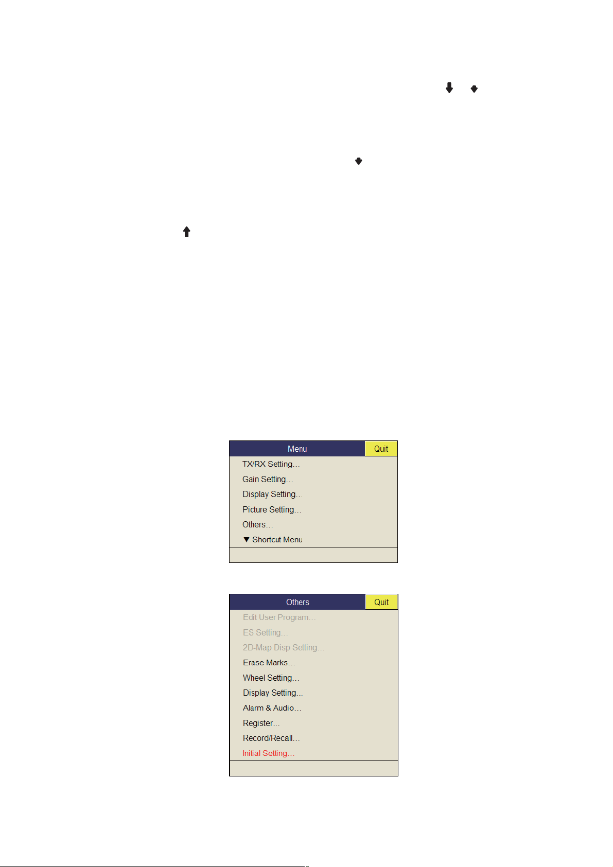
7. OTHERS MENU.....................................................................................................7-1
7.1 Erase Marks Menu .....................................................................................................7-1
7.2 Wheel Setting Menu ...................................................................................................7-2
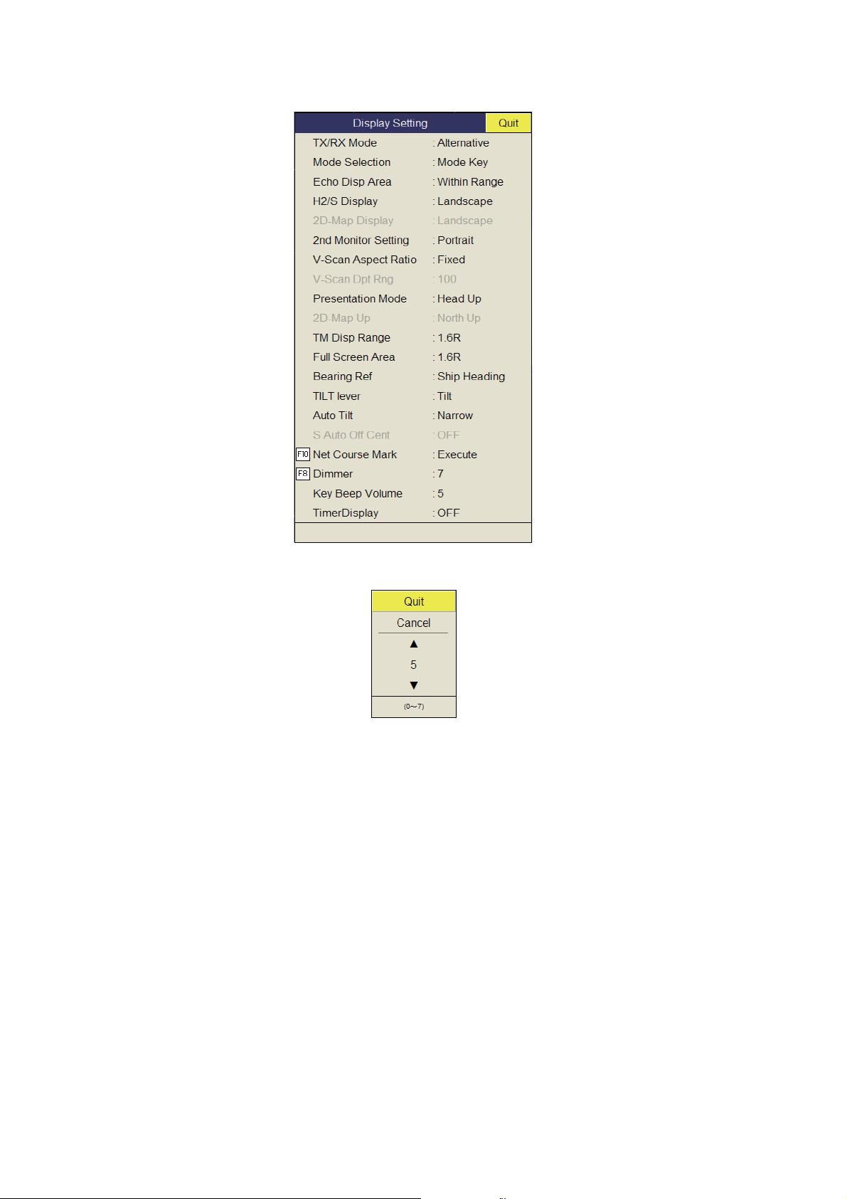
7.3 Display Setting Menu..................................................................................................7-3
7.4 Alarm & Audio Menu...................................................................................................7-5
7.5 Register Menu ............................................................................................................7-6
7.6 Initial Setting Menu.....................................................................................................7-7
8. RECORD/RECALL OPERATION..........................................................................8-1
8.1 How to Specify Where to Save Still Images ...............................................................8-1
8.2 How to Save Still Image .............................................................................................8-2
8.3 How to Display Saved Still Images.............................................................................8-2
8.4 How to Save Settings .................................................................................................8-4
8.5 How to Load Files.......................................................................................................8-5
8.5.1 How to load the setting information................................................................8-5
8.5.2 How to replay setting information...................................................................8-6
8.6 How to Delete Files ....................................................................................................8-7
9. MAINTENANCE, TROUBLESHOOTING .............................................................. 9-1
9.1 Preventive Maintenance.............................................................................................9-1
9.2 Hull Unit Maintenance ................................................................................................9-2
9.3 How to Replace Fuses ...............................................................................................9-3
9.4 Battery on the Mother Board ......................................................................................9-3
9.5 How to Clean the Filter in the Processor Unit.............................................................9-4
9.6 How to Clean the Trackball on the Control Units........................................................9-4
9.7 Troubleshooting..........................................................................................................9-5
vii
Page 10

TABLE OF CONTENTS
9.8 Warning Messages .................................................................................................... 9-6
9.9 Error Codes................................................................................................................9-7
9.10 Status Messages........................................................................................................9-8
9.11 Tests .......................................................................................................................... 9-8
9.11.1 Test menu ...................................................................................................... 9-8
9.11.2 Board test....................................................................................................... 9-9
9.11.3 Panel test .....................................................................................................9-10
9.11.4 Test pattern.................................................................................................. 9-11
9.12 How to Raise the Transducer from the Hull Unit...................................................... 9-11
9.12.1 How to raise the transducer automatically ................................................... 9-12
9.12.2 How to raise the transducer manually.......................................................... 9-13
APPENDIX 1 MENU TREE .......................................................................................AP-1
SPECIFICATIONS .....................................................................................................SP-1
INDEX..........................................................................................................................IN-1
viii
Page 11

FOREWORD
A Word the Owner of the FSV-85
Congratulations on your choice of the FURUNO FSV-85 Color Scanning Sonar. We are confident
you will see why the FURUNO name has become synonymous with quality and reliability.
Since 1948, FURUNO Electric Company has enjoyed an enviable reputation for quality marine
electronics equipment. This dedication to excellence is furthered by our extensive global network
of agents and dealers.
This equipment is designed and constructed to meet the rigorous demands of the marine environment. However, no machine can perform its intended function unless operated and maintained
properly. Please carefully read and follow the recommended procedures for operation and maintenance.
Thank you for considering and purchasing FURUNO equipment.
Features
The FSV-85 is a full-circle, multibeam electronic color scanning sonar which detects and displays
schools of fish on the monitor of your choice.
The main features of the FSV-85 are
• Cylindrical + sphere transducer provides 90 degrees vertical detection.
• Schools of fish can be searched from horizontal (range direction), vertical (depth direction) with
vertical and half-circle features.
• Function keys for direct access to desired menu item.
• Dual Display mode
• User programs for one-touch setup of equipment.
• Menu-driven operation.
• Fish histogram shows signal strength distribution of echo within estimate mark.
• Various marks and alphanumeric fishing and navigation information for intuitive operation.
• Storage and replay of picture and settings.
• Audio function for monitoring echoes along user-selected area through loudspeaker (option).
• Fish mark estimates fish speed.
• Fish estimate feature to compare the volume of two schools of fish.
• Net course mark shows probable drift of net against tidal current.
• Pitching and rolling compensation for stable picture always.
ix
Page 12
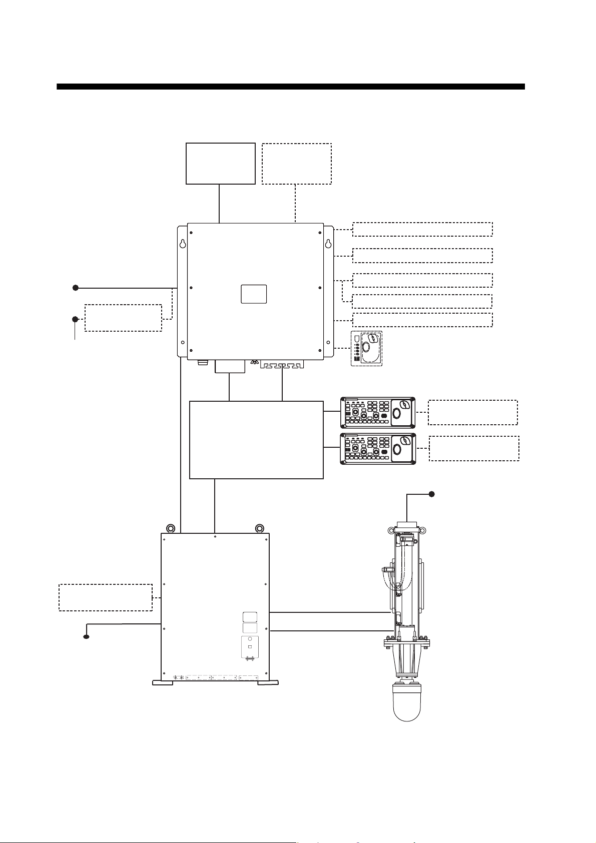
SYSTEM CONFIGURATION
MAIN SW
FUSE
Standard configuration is shown with solid line.
Monitor Monitor
USB device (mouse, etc.)
12-24 VDC
Rectifier
RU-1746B-2
100/110/115/
220/230 VAC
Satellite Compass
SC-30/50/100
Processor Unit
FSV-8503
IF Unit
FSV-8502
Transceiver Unit
FSV-851A
Junction Box FI-5002
NMEA IEC 61162-1 device
NMEA IEC 61162-1 device
Speaker
Sub Control Unit
FSV-853
Control Unit
FSV-8501
Remote Controller
FSV-854
Remote Controller
FSV-854
200-220 VAC
3
Hull Unit
(80 kHz)
FSV-8431 - 8434
FSV-8441 - 8444
(70 kHz)
FSV-8531 - 8534
FSV-8541 - 8544
φ
, 50/60 Hz
100/110/115/
220/230 VAC
φ
, 50/60 Hz
1
x
FUSE
Page 13
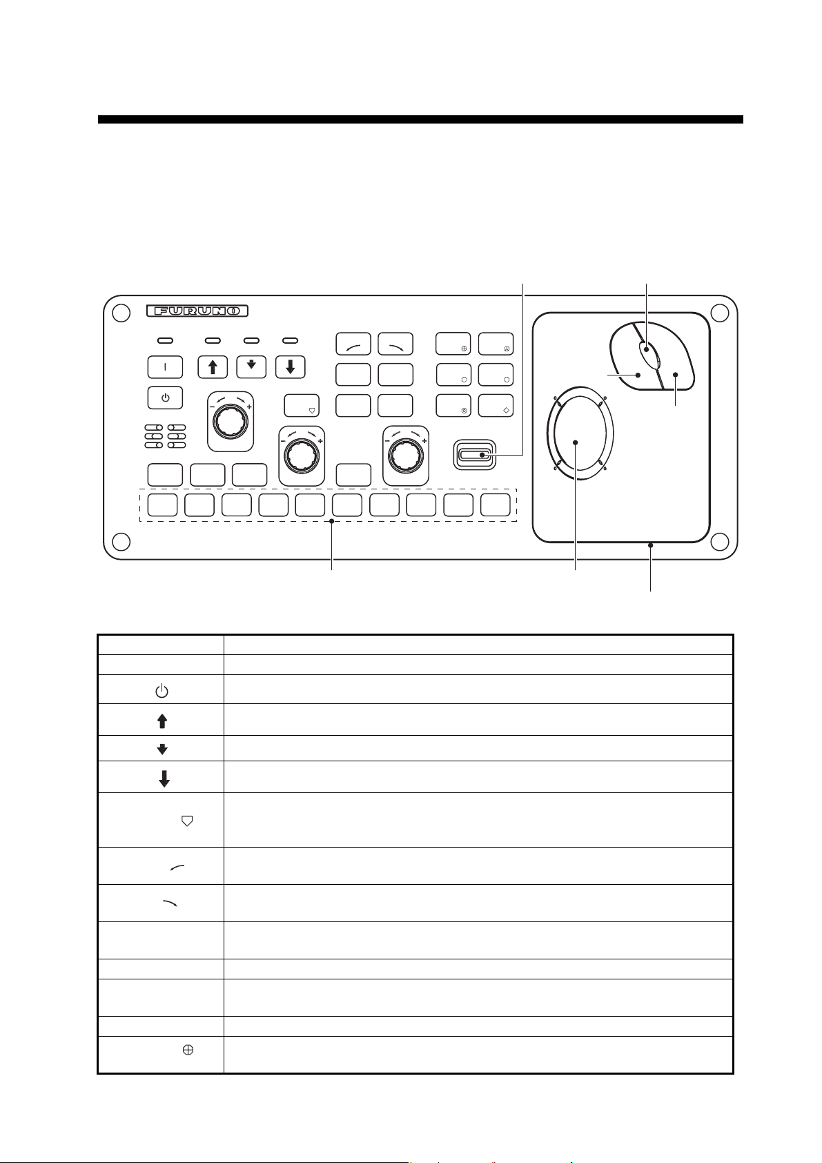
1. OPERATIONAL OVERVIEW
1.1 Control Description
1.1.1 Control unit
MENU/
ESC
䌆1
AUTO
TILT
䌆2
USER PROG
MODE
䌆3
DISP
䌆4
SHOOT
GAIN
䌆5
V1/S
AUTO
TRAIN
R/B
AUDIO
H/V/S
䌆6
V2
OFF
CENTER
DELETE
MARK
RANGE
䌆7
䌆8
EVENT
ESTIMATE
TAR GET
LOCK
䌆9
EVENT
ESTI-
1
MATE
FISH
䌆10
Function key
Key Function
| Turns power on.
Tilt lever
2
Trackball
Scrollwheel
Left-click
button
Right-click
button
Trackball unit
Turns power off.
Raises the transducer.
Lowers the transducer (mid protrusion).
Lowers the transducer (full protrusion).
• Enters the net shooting mark or own ship mark (horizontal mode).
SHOOT
• Displays the net shoot data and net depth data (horizontal mode, slantmode).
V1/S
V2
AUTO TRAIN
• Sets vertical cross section bearing.
• Sets train by 5° clockwise.
• Sets vertical cross section bearing.
• Sets train by 5° counterclockwise.
Automatic transducer train width on audio bearing mark (horizontal mode), vertical bearing mark (vertical mode).
OFF CENTER Off centers own ship’s position (horizontal mode, slant-mode).
R/B AUDIO
• Displays range and bearing marks (horizontal mode, slant mode).
• Sets the audio bearing.
DELETE MARK Deletes trackball-selected mark.
EVENT
• Inscribes event mark 1 or own ship mark (horizontal mode).
• Inscribes event mark 1 (slant mode).
1-1
Page 14
1. OPERATIONAL OVERVIEW
Key Function
EVENT
ESTIMATE 1
ESTIMATE 2
TARGET
LOCK
FISH
MENU/ESC Short-press: Opens or closes the menu; returns to the previous menu.
AUTO TILT Sets auto tilt angle.
DISP MODE Selects display mode.
H/V/S • Selects the mode tab on the menu.
Function key
(F1 to F10)
USER PROG
control
GAIN control Adjusts gain for horizontal, half-circle and vertical scans.
RANGE control Selects the display range for horizontal, half-circle and vertical scans.
Tilt lever Sets transducer tilt angle for horizontal and half-circle scan.
Trackball unit Trackball:
• Inscribes event mark 2 or own ship mark (horizontal mode).
• Inscribes event mark 2 (slant mode).
Turns the estimate mark on/off (horizontal mode, slant mode).
Enters target lock mark (horizontal mode, slant mode).
Enters fish mark (horizontal mode, slant mode).
Long-press: Closes all menus.
• Selects mode (horizontal/vertical, horizontal/half-circle, horizontal/horizontal 2) to adjust sensitivity, select range, set tilt, and user program number.
Execute assigned program.
Selects user-programmed settings.
• Positions cursor.
• Selects items, options on menu.
Left-click button:
• Confirms the selected item.
• Selects the item to drag and drop.
Scrollwheel:
• Rotate: Sets numeric data.
• Rotate: Selects menu item.
• Rotate: Sets tilt angle, range, bearing/train angle, gain, and user program
number.
• Push: Confirms the selected item.
• Push: Shows the [Select Mark] window.
Right-click button:
• Shows pop-up menu.
• Confirms the selected item.
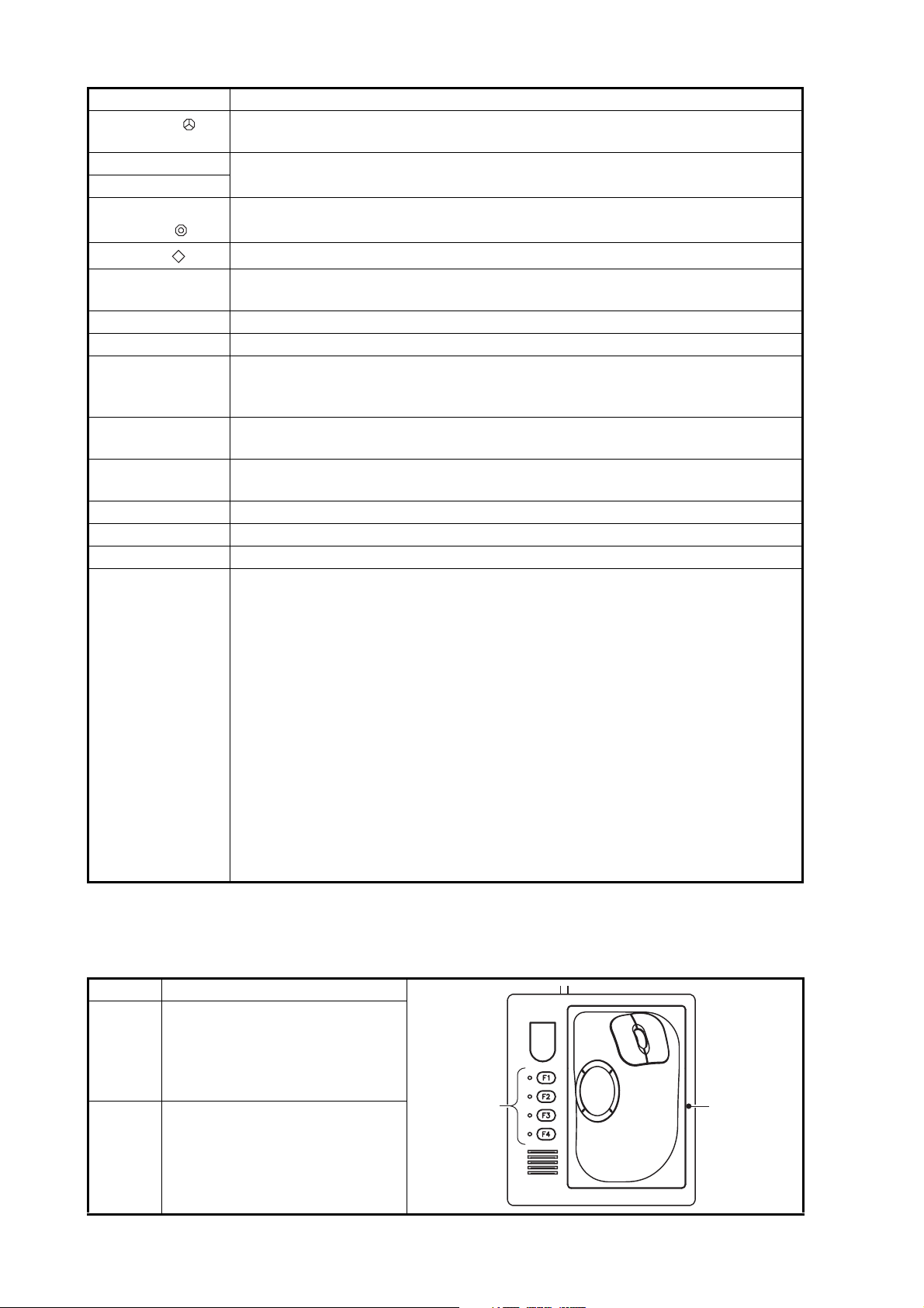
1.1.2 Sub control unit (option)
The sub control unit lets you control the sonar from a remote location.
No. Function (on control unit)
Same as F1, F2, F3 and F4 key.
1
2
(The program can be changed.
See section 6.2.4.)
Same as trackball unit on control unit.
1-2
21
Page 15
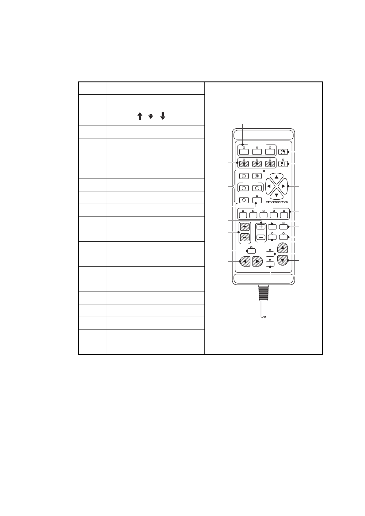
1.1.3 Remote controller (option)
The remote controller lets you control the sonar from a remote location.
Note: Keep the remote controller away from water and water splash. Hook the remote
controller to the bracket when it is not in use.
No. Function (on control unit)
1 Same as F1, F2 and F3 key.
1. OPERATIONAL OVERVIEW
2
Same as key.
,䇭䇭,
䇭
3 Same as right-click button.
4 Same as the left-click button.
Same as [EVENT], [ESTI-
5
MATE], [TARGET LOCK] and
[FISH] keys.
6 Same as trackball.
7 Same as OFF CENTER key.
8 Same as USER PROG control.
9 Same as GAIN control.
10 Same as RANGE control.
11 Same as SHOOT key.
12 Records the current picture.
13 Shows the still image window.
14 Same as MODE key.
10
15
16
1
䌆䋱 䌆䋲 䌆䋳
2
5
1 2
OFFCENT
3
4
6
7
345
2
1
9
SHOOT
MEMO
DISP
RECALL
MODE
8
11
12
13
14
AUTO
AUTO
H/V/S
17
18
19
15 Same as AUTO TRAIN key.
16 Same as V1/S, V2 key.
17 Same as AUTO TILT key.
18 Same as TILT lever.
19 Same as H/V/S key.
1-3
Page 16
1. OPERATIONAL OVERVIEW
㪦
Change of the lamps
CAUTION
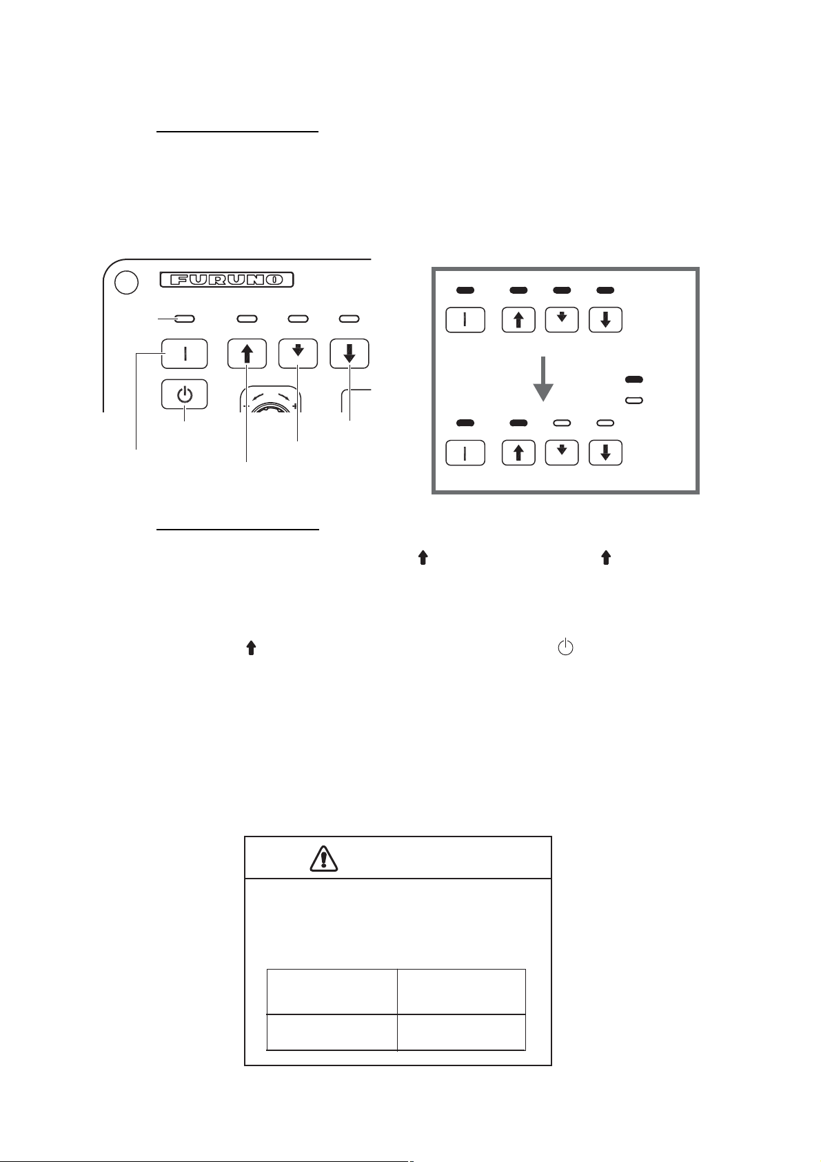
1.2 Turning the Power On/Off
Turning the power on
Press the POWER ON ( | ) switch. A beep sounds, and the display changes in the following sequence: FURUNO display → model display → board test display. Then lamp
above the switch changes as below. The last-used mode is activated in approximately
140 seconds after turning the power on.
Lamp
When pressing the POWER ON switch
㪪㪟
Change of the lamps
Lamp
: ON
: OFF
POWER OFF
switch
POWER ON
switch
Retraction key
Full protrusion key
Mid protrusion key
After the board test is completed
Turning the power off
1. First retract the transducer with the key. The lamp above the key blinks while
the transducer is being raised and lights steadily when it is fully raised.
Note: While raising the transducer, the ship speed must be no more than 15 knots
to prevent damage to the transducer and hull unit.
2. After the key lights steadily, press the POWER OFF ( ) switch for more than
three seconds.
Note: The transducer is automatically retracted into the tank if the POWER OFF
switch is pressed before retracting the transducer. However, for safety purposes,
retract the transducer before turning off the power.
1.3 Lowering, Raising the Transducer
1-4
CAUTION
Maximum speed while the transducer is
projected and being raised or lowered
is as below, to prevent damage to the
transducer.
Projected
Max. 18 kn
Raising/
Lowering
Max. 15 kn
Page 17
1.3.1 Lowering the transducer
With the boat at the fishing ground and the power on, press the or key. The lamp
above the key pressed blinks during lowering and lights when the transducer is completely lowered to selected protrusion distance. It takes about 21 seconds for full protrusion in case of 800 mm stroke and 28 seconds in case of 1100 mm stroke. In normal
use fully lower the transducer. If the transducer becomes entangled in the net for some
reason, partially raise the transducer with the key. This raises the transducer by 300
mm.
1.3.2 Raising the transducer
Press the key to raise the transducer. The lamp above the switch blinks while the
transducer is being raised and lights steadily when it is fully raised.
1.4 Screen Brilliance, Panel Dimmer
1.4.1 Screen brilliance
1. OPERATIONAL OVERVIEW
The brilliance of an external monitor cannot be adjusted from the Control Unit. Use the
associated control on the monitor.
1.4.2 Panel dimmer
1. Press the MENU/ESC key to open the main menu.
2. Select [Others] then push the left-click button.
1-5
Page 18
1. OPERATIONAL OVERVIEW
3. Select [Display Setting] then push the left-click button.
4. Select [Dimmer] then push the left-click button to show the setting box.
5. Select S (increase) or T (decrease).
6. Push the left-click button several times to select a value.
7. Select [Quit] on the setting box then push the left-click button to close the box.
8. Long-press the MENU/ESC key to close all menus.
Note: The default function of the F8 key adjusts the panel dimmer.
1.5 Display Mode, Display Division
There are six display modes; Horizontal, Horizontal1 + Horizontal2*, Slant (single display), Horizontal + Slant*, Vertical1* and Vertical 1 + Vertical 2*.
1-6
*: If the FSV-85 is fitted with dual monitors, you can select how the picture data is
shown on two displays; Dual Display or Sub Display. For details, see page 7-8.
Page 19
1. OPERATIONAL OVERVIEW
Echo picture
display (Within
Range)
Echo picture
display (Full
Screen)
Numeric/graphic
data display
Numeric/graphic
data display
N
H1
1
85
1
1
W E
Main monitor
2
N
H2
W
N
300
1
2
3
S
Sub monitor
E
3
Ex; Dual Display (H1 + H2 mode)
Display format
As shown in the illustration below, you have two choices with which to show the echo
display. See page 7-3 for how to select the display method. For the numeric/graphic
data display, see page 5-1.
Echo picture
Echo picture
display (Within
display (Within
Range)
Range)
Echo picture
Echo picture
display (Full
display (Full
data display
data display
Numeric/graphic
Numeric/graphic
Screen)
Screen)
data display
data display
Numeric/graphic
Numeric/graphic
1-7
Page 20
1. OPERATIONAL OVERVIEW
1.5.1 How to select a display mode
Press the MODE key several times until the desired display appears. The default
modes are Horizontal, Horizontal1 + Horizontal2, Vertical1 and Vertical1 + Vertical2.
You can program the MODE key to show any or all of the modes mentioned above.
For further details, see "Display Mode" on page 7-6.
The MODE key may be programmed to show a pull-down menu instead of a conventional menu.
1. Push the right-click button on the numeric/graphic data display.
2. Select [Display Mode] then push the left-click button.
3. Select the mode to display then push the left-click button.
1.5.2 Display mode pictures
Below are typical pictures. For sake of brevity, indications and marks are not shown.
Horizontal mode
This mode provides 360-degree coverage around the vessel and it is useful for general search. For further details, see chapter 2.
NUMERIC/
GRAPHIC
DATA
DISPLAY
1-8
Horizontal mode
Page 21
1. OPERATIONAL OVERVIEW
H2 mode
This mode provides two horizontal screens (H1 and H2) in one of the configurations
shown below. The default configuration, Landscape, shows two horizontal displays,
one up and one down. Other configurations available are as shown below. Desired
configuration may be chosen with H2/S2 Display in the [Display Setting] menu. For further details, see chapter 2.
N
H1
H2
1
85
1
1
2
N
NUMERIC/
GRAPHIC
DATA
1
1
2
DISPLAY
LANDSCAPE PORTRAIT
㪟㪈 㪟㪉
N
1
2
3
1
2
3
3
1
2
3
1
2
3
1
1
2
3
1
2
S
N
N
NUMERIC/
1
2
3
1
2
3
S
GRAPHIC
DATA
3
DISPLAY
2
1
2
3
H1
NUMERIC/
E
GRAPHIC
DATA
DISPLAY
Zoom-out window
W
W
H2
1
2
N
1
2
3
1
85
300
1
2
3
2000
S
E
3
1
2
3
2
1
2
3
1
1
2
3
1
2
3
3
1
2
3
S
INSET
H2 mode
Slant mode, single display
The Slant mode shows a 180-degree cross section, using chosen tilt angle and train
setting. For further details, see chapter 4.
Bottom
School of fish
Sea surface reflection
Slant mode (single display)
1-9
Page 22
1. OPERATIONAL OVERVIEW
H and S mode
This mode provides horizontal and slant modes in one of the configurations shown below. The default configuration, Landscape, shows two horizontal displays, one up and
one down. Other configurations available are as shown below. Desired configuration
may be chosen with H2/S Display in the [Display Setting] menu. For further details,
see chapter 4.
H
S
Landscape display (Slant mode on bottom half)
Numeric/graphic data display
N
H
W
W
S
N
1
85
1
2
3
1
3
2
3
1
2
1
2
2000
3
2
1
1
2
3
1
2
3
S
Slant mode in inset
1
2
3
300
E
2
S
H
N
1
2
3
1
2
3
3
1
2
3
1
2
3
1
1
2
3
1
2
S
S
N
S
Portrait display (Slant mode at right half)
E
3
1
3
Numeric/graphic data display
Zoom-out window
Numeric/graphic data display
H and S mode
1-10
Page 23
1. OPERATIONAL OVERVIEW
㪈㪇㪇㪇
㪌㪇㪇
㪈㪇㪇㪇
㪌㪇㪇
V1 and V2 modes
The V1 and V2 modes show a vertical slice of the bearing selected by the vertical
bearing mark on the horizontal display. The vertical 2 mode provides two vertical slices. For further details, see chapter 3.
㪥
㪟 㪟
㪮
㪈㪇㪇㪇 㪈㪌㪇㪇
㪌㪇㪇
㪭㪈
㪌㪇㪇
㪌㪇㪇
㪉㪇㪇㪇
㪈㪇㪇㪇
㪪
㪭
NUMERIC/
GRAPHIC
㪜
DATA
DISPLAY
V1 mode
Vertical mode
1.6 How to Adjust the Gain
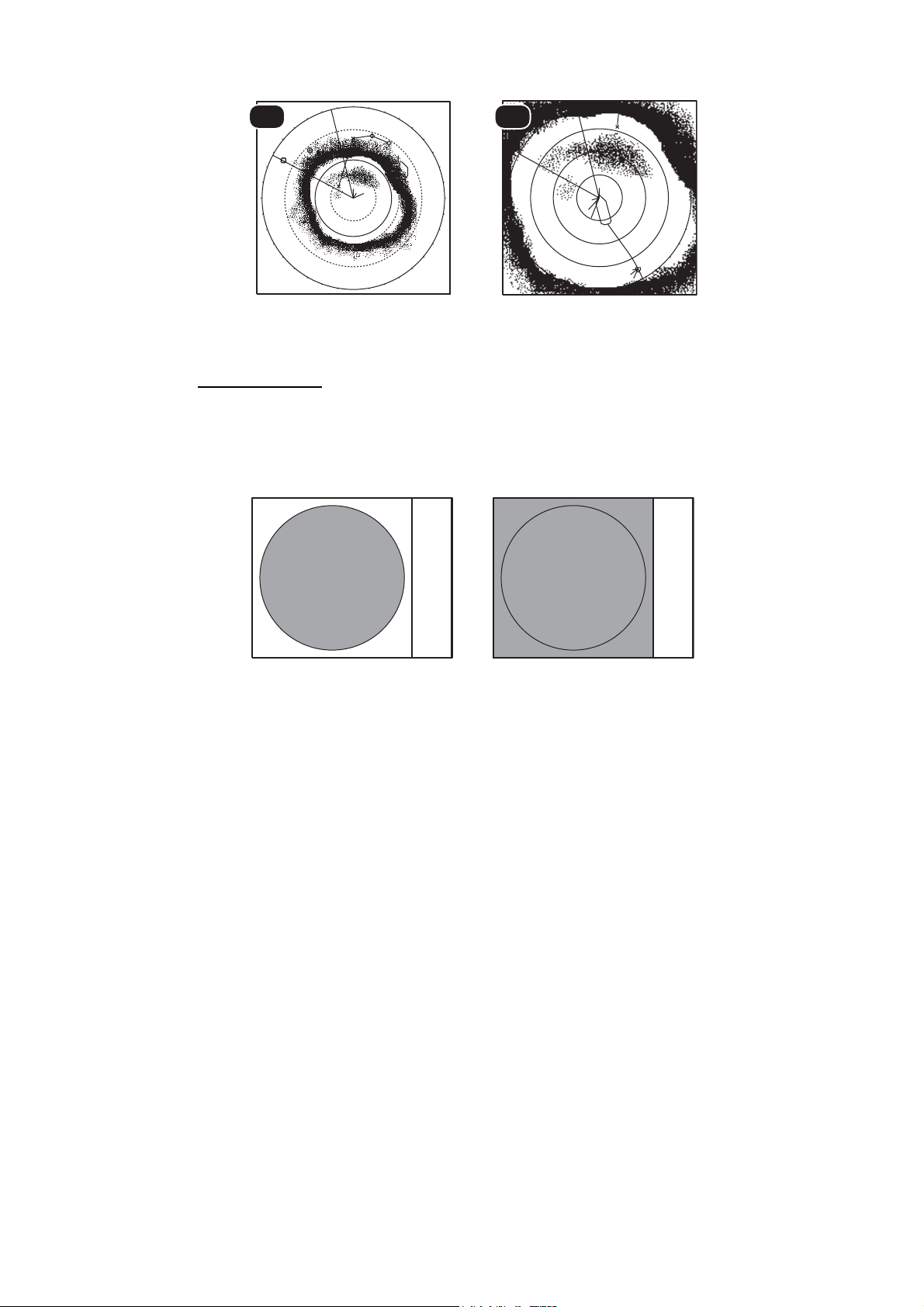
The GAIN control adjusts receiver gain (sensitivity) for the horizontal, slant and vertical modes. Adjust it so fish echoes are clearly displayed with minimal noise on the
screen. Too high a gain setting not only displays excess noise and makes it difficult to
discriminate wanted echoes but also causes bottom echoes to be painted in strong
colors, resulting in echoes being masked by bottom reflections. Normally, set the control somewhere between positions 3 and 7.
㪥
㪮
㪈㪇㪇㪇㪈㪌㪇㪇 㪌㪇㪇 㪈㪇㪇㪇 㪈㪌㪇㪇
㪌㪇㪇
㪉㪇㪇㪇
㪈㪇㪇㪇
㪭㪉 㪭㪈
㪪
V1 & V2 mode
㪈㪉
NUMERIC/
GRAPHIC
㪜
DATA
㪌㪇㪇
DISPLAY
㪌㪇㪇
㪈㪇㪇㪇
Gain too low
Gain proper
Gain too high
1. If the horizontal and vertical modes are active, press the H/V/S key to show the
range and gain indications of the mode you wish to adjust. Pressing the H/V/S key
changes the color of the range and gain indications to orange.
• H1/H2: Horizontal1 or horizontal2
• H/S: H or S display
• V1/V2: H or V display
2. Adjust the GAIN control.
New gain setting is momentarily displayed in large characters at the top of each display. The setting value is always displayed next to “G“. (For the vertical display, the
gain indication is shown at the bottom of the display.)
Note: The gain can also be adjusted from the gain indication. Put the cursor on the
gain indication to highlight it in yellow then roll the scrollwheel.
1-11
Page 24

1. OPERATIONAL OVERVIEW
1.7 How to Use the Menu
Most operations are carried out from the menu. This section provides basic menu operating information.
1. Press the MENU/ESC key to open the main menu.
Menu title
Select “Shortcut Menu”
to show the menu title
you programmed.
(See section 6.1.)
The descriptions for the selected item appears in this field.
Select QUIT with
trackball and then left
click to close the menu.
“...” means that this
item has sub menus.
Note: You can also show the main menu by pushing the right-click button to show
the pop-up menu. See page 1-14.
2. Operate the trackball to place the arrow cursor on the item you want to select. The
yellow cursor marks the current selection. You can also use the scrollwheel to select a menu item.
3. Push the left-click (or right-click, scrollwheel) button. If you selected [TX/RX Setting] at step 2 for example, the following menu appears.
Scanning mode tab
This icon means
that this item is
assigned to a
function key.
4. Press the H/S/V key to select the display mode.
• H1, H2 tab: Items for horizontal display setting
• S tab: Items for the slant display setting
• V tab: Items for the vertical display setting
Items which you cannot set are shown in gray.
5. Select the item then push the left-click button.
(Numeric window) (Item window)
1-12
Page 25
1. OPERATIONAL OVERVIEW
6. Select the setting.
• (Numeric) Select S to increase the value then push the left-click button (or roll
the scrollwheel upward). To decrease the value, select T and push the left-click
button (or roll the cursor scrollwheel downward).
• (Items) Select an item then push the left-click button.
7. Select [Quit] on the setting box then push the left-click button to close the box. If
you want to cancel the setting, select [Cancel].
8. Long-press the MENU/ESC key to close all menus.
You can also close all menus by selecting [Quit] on the active menu and longpushing the left-click button.
Note 1: You can relocate menu windows. Use the trackball to put the arrow cursor on
the menu is title (blue when menu is active), push the left-click button, drag window to
new location then release the left-click button. The position of the menu windows is
saved.
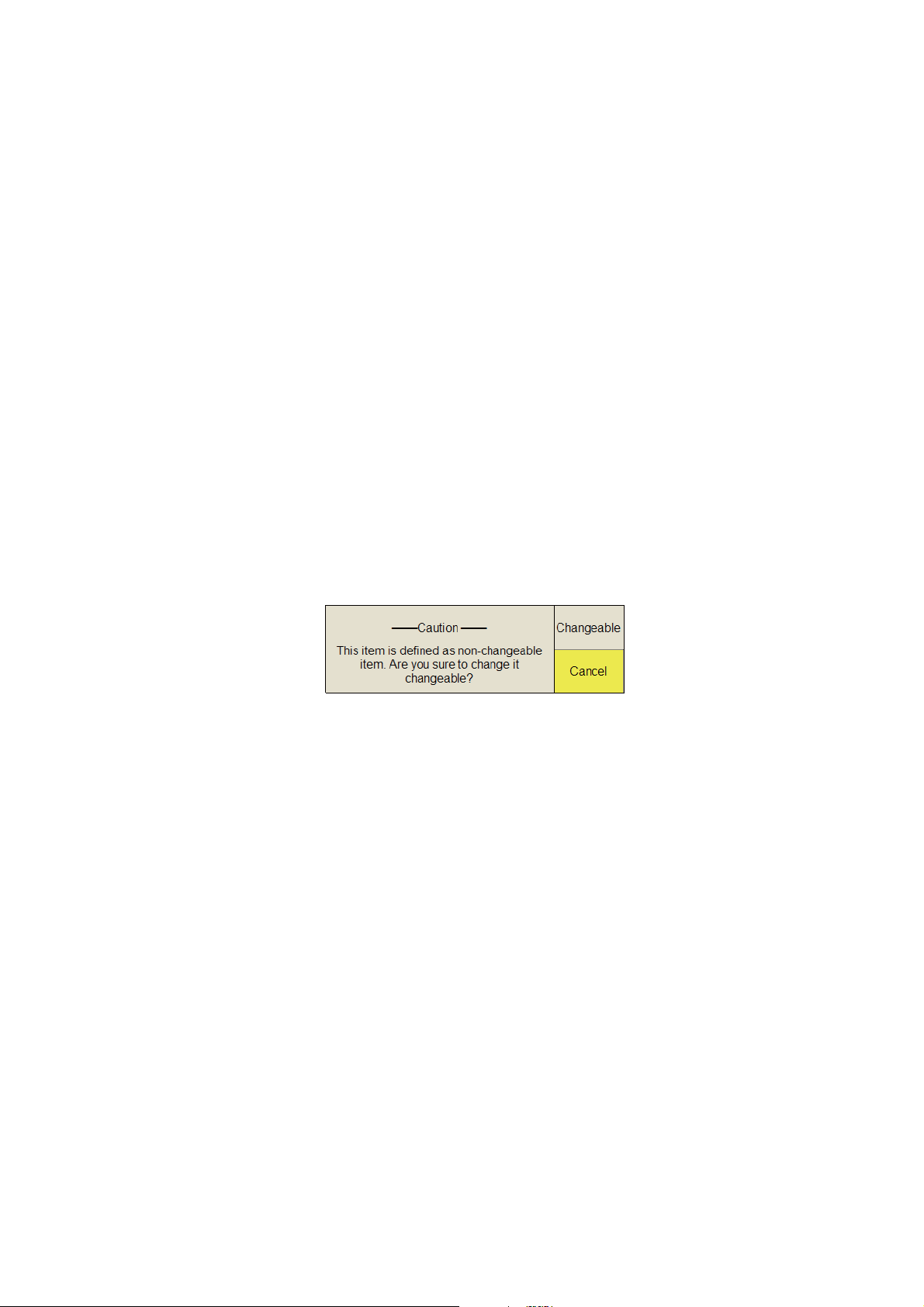
Note 2: In the default setting, the sub menu item [Initial Setting] in the [Others] menu
and some items in the [Initialization] menu are shown in red. This means these items
are locked to prevent accidental change of setting. When you open one of these sub
menus and select an item, the confirmation message shown below appears. To
change the setting of the selected item, select [Changeable] and push the left-click
button to show the dialog box for the item. To escape, select [Cancel] then push the
left-click button.
If you do not want to show the confirmation message above, see page 7-16.
Note 3: If two menu items are functionally related, the setting of one menu item causes restriction to another menu item. In this case, the equipment ignores both settings
to use different ones or invalidates the setting of the item encountering restriction. The
invalid setting value or menu item is shown in gray.
1-13
Page 26
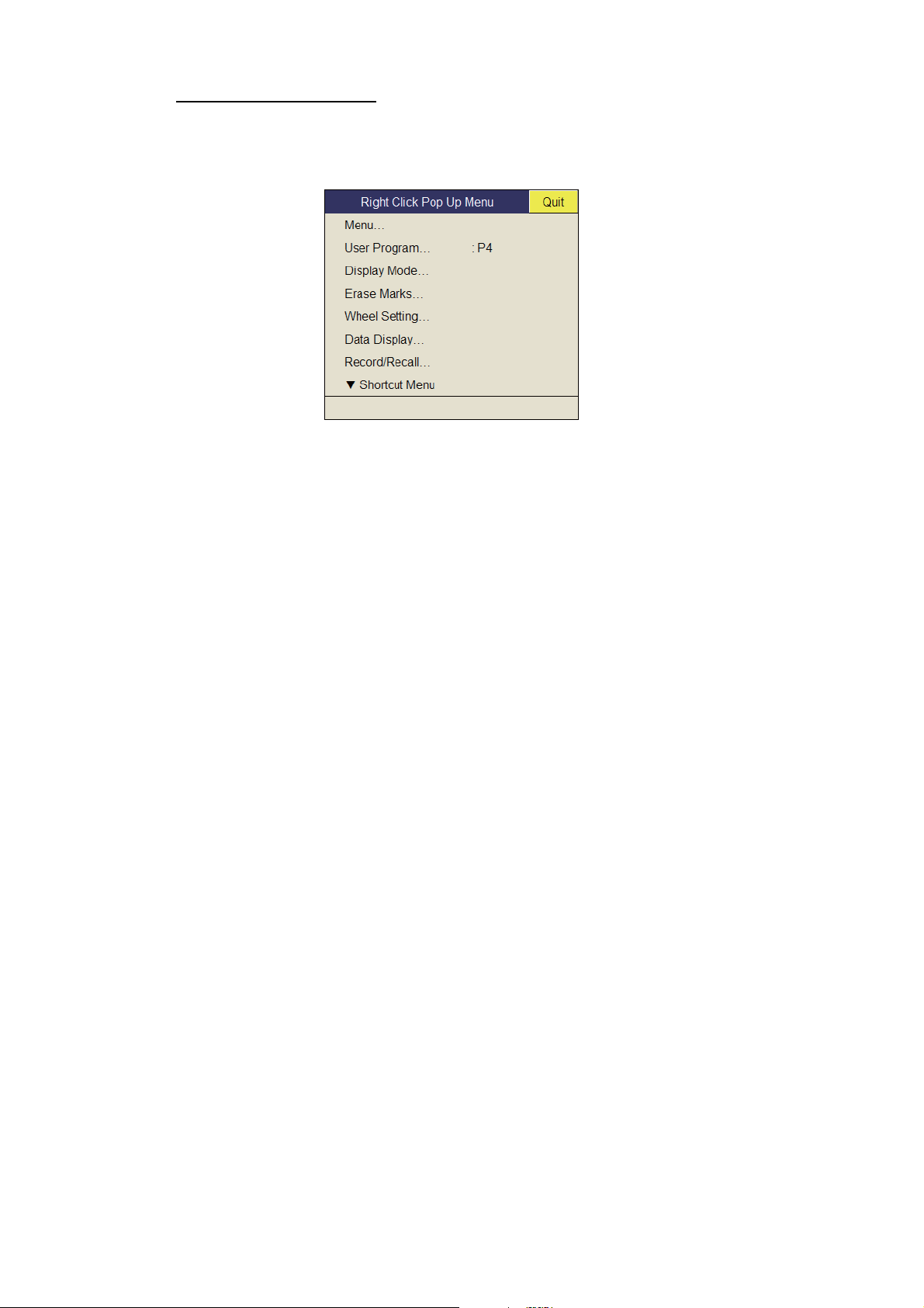
1. OPERATIONAL OVERVIEW
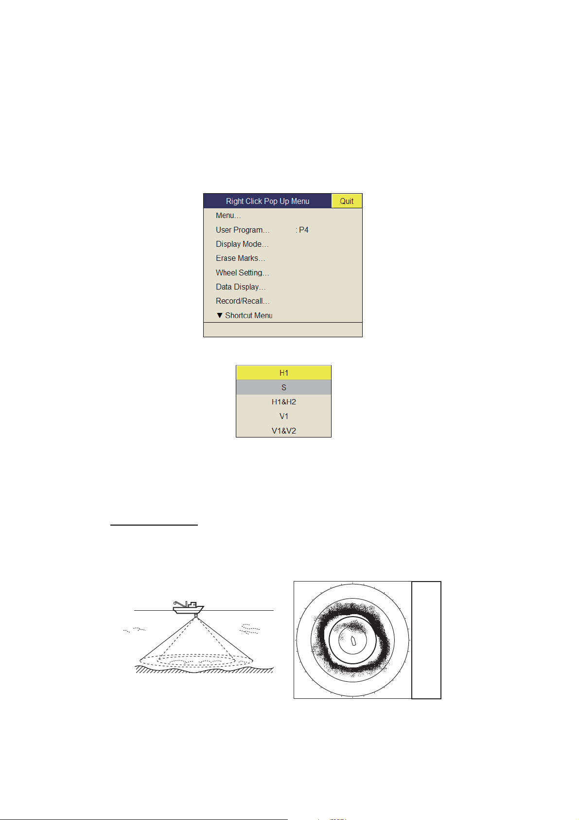
Pop-up menu operation
Push the right-click button on the numeric/graphic data display to show the pop-up
menu. These items can be accessed from the main menu.
1-14
Page 27
2. HORIZONTAL MODE
2.1 Basic Operating Procedure
2.
Lower transducer.
: Mid protrusion
1.
Turn on power.
䋺Full protrusion
MENU/
ESC
䌆1
AUTO
䌆2
TILT
USER PROG
䌆3
DISP
MODE
䌆4
SHOOT
GAIN
䌆5
6.
Adjust gain.
V1/S V2
OFF
AUTO
CENTER
TRAIN
R/B
DELETE
AUDIO
MARK
H/V/S
䌆7
䌆6
4.
Press to choose the screen (horizontal or vertical,
EVENT
ESTIMATE
TARG ET
LOCK
RANGE
䌆8
5.
Select range.
EVENT
ESTI-
1
2
MATE
FISH
䌆10
䌆9
7.
Set tilt angle.
or horizontal1 or horizontal2, or horizontal or half-circle)
to adjust gain and range.
3.
Select horizontical display.
Control unit
2-1
Page 28
2. HORIZONTAL MODE
2.2 Indications and Markers
2.2.1 Horizontal mode, full-screen display
The full-screen horizontal display provides a 360° picture around the boat. To display
the full-screen horizontal picture, press the DISP MODE key.
Target lock mark
Net shoot data
Distance run from shooting
Time from shooting
Trackball data
-
Slant range
-
Horizontal range
-
Depth
-
Relative bearing
or True bearing*
Wind speed, direction*
Latest event marks
Auto train mark
Audio bearing mark
Heading mark
North mark*
Own ship mark
Current (tide)
mark*
Range ring
Bearing scale
Event mark
Event mark data
-
Horizontal range
-
Present depth
-
Depth at time of
mark entry
-
Relative bearing
or True bearing*
* Requires appropriate sensor.
** Appears with head-up mode.
㪙 㩷㩷㪈㪈㪌°
㪮 㪈㪉㫄㪆㫊
㪉㪐㪇
㪉㪏㪇
㪮
㪉㪍㪇
㪉㪌㪇
㩷㩷㪋㪏㫄
㩷㩷㩿㪉㪈㪇㫄㪀
㪙 㪊㪊㪇°
㪊㪇㪇
㪉㪋㪇
㪈㪋㪏㫄
㪈㪋㪏㫄
㪈㪋㪉㫄
㪋㪌㫄
Cursor
position
Fish track*
㪇㪅㪌㪈㪥㪤
㪌㪑㪊㪉
㪊㪉㪇
㪊㪈㪇
A
㪉㪊㪇
㪈㪍㪏㫄
㩷㩷㪋㪏㫄
㩷㩷㩿㪉㪈㪇㫄㪀
㪙 㪊㪋㪇°
㪊㪋㪇
㪊㪊㪇
㪈
㪉
㪉㪉㪇
㪉㪈㪇
㪊㪋°㪌㪍㪅㪎㪏㪐㪥
㪈㪉㪊°㪋㪌㪅㪍㪎㪏㪜
Fish mark
Heading
direction*,**
㪥
㪊㪌㪇
㪈
㪉
㪊
㪈
㪉
㪊
㪈㪌㪇
Range ring
data
㪈㪐㪇
㪪
Net
sonde mark*
Line connecting
fish marks
㪈㪇
㪈
䊶
䊶
䊶
䊶
䊶
䊶
䊶
䊶
䊶
䊶
䊶
䊶
䊶
䊶
䊶
䊶
䊶
䊶䊶
䊶
䊶䊶䊶
䊶
㪏㪌
㪊
㪉
㪈
㪉
㪊
㪈㪎㪇
Net shoot
mark
Latest fish mark
㪉㪇
㪊㪇
㪈
㪈
㪉
㪊
㪈
㪉
㪊
㪈㪌㪇
㪩 㪈㪋㪍㫄
㪈㪍㪇
㪙 㪉㪐㪇°
Range mark and
audio bearing
mark data
㪟㪄㪬㪧
㪋㪇
㪈㪋㪇
㪟㩷㪩 㪋㪇㪇㫄
㪘㪬㪫㪦
㪌㪇
㪈㪊㪇
㪪 㪈㪉㪅㪊㫂㫅
㪚 㪉㪌㪍°
㪈㪎°㪫
㩿㪉㪈°㪀
㪞㪈㪅㩷㪇
㪧 㩷㩷㪏
㪍㪇
㪎㪇
㪈㪇㪇
㪈㪈㪇
㪈㪉㪇
㪉㪊㪇㫄
㪎㪇㫄
Presentation mode
Display mode
Scan data
Range
Current auto tilt
Gain
User program no.
Fish movement
vector
Fish estimate mark no.
Fish estimate mark
㪏㪇
Fish estimate mark data
㪜
Range
mark
Cursor
Own ship position mark
Ship's track*
Target lock/fish movement data
-
Horizontal range
-
Depth
-
Speed
-
Course
2-2
Note 1: When the settings listed below are changed, the setting value is shown at the
top of the display for five seconds. The location of the setting value can be changed.
Contact your dealer for details.
• Gain (See section 1.6.)
• Tilt angle (See section 2.4.)
• Automatic training (See section 2.13.3.)
• Display range (See section 2.3.)
• Automatic tilt (See section 2.4.2.)
• User program (See section 6.3.1.)
Note 2: The color of the event mark, fish mark, and fish estimate mark can be changed
on the menu: main menu → [Others] → [Initial Setting] → [Mark Display] → [Mark Color].
Page 29
2.2.2 Horizontal2 mode
The H2 mode shows one of three kinds of horizontal display combinations: Landscape, Portrait or Inset as shown on page 1-9. Follow the procedure shown below to
select a combination display. The zoom-out display (shown on the inset mode) can be
moved by drag and drop operation and its size changed from the menu.
1. Press the MENU/ESC key to show the main menu.
2. Select [Others] then push the left-click button.
3. Select [Display Setting] then push the left-click button.
2. HORIZONTAL MODE
4. Select [H2/S Display] then push the left-click button.
5. Select the desired option then push the left-click button.
6. Select [Quit] on the setting box then push the left-click button.
7. Long-press the MENU/ESC key to close all menus.
Note: Range, tilt angle, gain and program keys can be adjusted for each display.
2-3
Page 30
2. HORIZONTAL MODE
2.3 Display Range
The RANGE control selects the
detection range and six ranges
are preset at the factory. The
range selected is momentarily displayed in large characters at the
top of the screen. Range is always
displayed next to “R“ at the top
right of the screen.
Default settings for the display range (unit: m)
Range No. 1 2 3 4 5 6
Detection range 100 200 400 600 800 1000
Note: Ranges can be preset at the [H-Scan Range] on the [Others] - [Register] menu.
See page 7-6.
1. If the vertical or slant display is active, press the H/V/S key to select the horizontal
display. If the two horizontal displays are active, press the H/V/S key to select H1
or H2 to change the range. The range and gain indications of the horizontal mode
must be in orange to change the range (and gain).
Bottom
Range displayed on display
Surface
2. Operate the RANGE control to select a range.
Note 1: The range can also be adjusted from the range indication. Put the cursor on
the range indication to highlight it in yellow then roll the scrollwheel.
Note 2: In the target lock function, the range is automatically changed according to
target position if [Tilt Interlock] on the [Target Lock] menu is selected to [Tilt & Range].
2-4
Page 31

2.4 Tilt Angle
The tilt angle shows the direction to which the sound wave is emitted. When the sound
wave is emitted horizontally, the tilt angle is said to be 0° and when vertically, 90°. The
tilt angle can be set between -5° (upward) to 90° (downward), in increments of 1°. The
tilt angles for horizontal 1 and horizontal 2 modes can be set independently of one another.
2.4.1 How to set the tilt angle
To set a tilt angle manually, operate the TILT control. Watch the tilt angle indication
and tilt angle indicator at the top right corner of the screen. The tilt angle is shown next
to “T“ at the top right of the screen.
Select tilt angle depending on target fish. For surface fish select a shallow angle
(about 5°) and for bottom fish, a deep angle.
-5-degree
0-degree horizontal direction (tilt angle 0-degree)
Transducer
Tilt angle setting range
2. HORIZONTAL MODE
Note 1: In the factory default condition, the tilt angle can also be adjusted by rolling
the scrollwheel.
Note 2: The tilt angle can also be adjusted from the tilt angle indication. Put the cursor
on the tilt angle indication to highlight it in yellow then roll the scrollwheel.
Note 3: The TILT control functions as a bearing setting lever when the following con-
ditions are met: [Tilt Lever] in the [Display Setting] menu is selected to [Tilt & V1], and
the vertical display is chosen in the vertical mode.
2.4.2 Automatic tilt
The AUTO TILT key automatically scans the tilt angle within the selected width. This
is useful when you want to find the center depth of a school of fish. Wide tilt angle is
activated from the [Auto Tilt] on the [Others] - [Display Setting] menu.
1. Press the AUTO TILT key to select auto tilt angle desired. Each time the key is
pressed the auto tilt angle changes in the following sequence.
OFF [±1° - 4°]
+90-degree
[±2° - 6°]
[±3° - 8°
]
(Narrow)
OFF
[±2° - 10°]
[±4° - 16°]
[±6° - 20°
]
(Wide)
2-5
Page 32

2. HORIZONTAL MODE
2. If necessary operate the TILT control to change center tilt angle.
In automatic tilt, “AUTO” is displayed at the top right corner. To disable automatic
tilt, select OFF at step 1.
N-UP
H
R 400m
AUTO
17°T
(21
G10
P 8
Automatic tilt angle (narrow) with
Auto tilt is active
°
)
Current tilt angle
AUTO TILT key
Range (m) Width 1 Width2 Width3 Period
60, 100
150, 200
300, 400
500, 600
700, 800
900, 1000
Over 1100
±4°*;
±2°
±1°
±1°
±1°
±1°
±1°
±6°*
±4°
±2°
±2°
±2°
±2°
±2°
±8°*
±6°*
±4°*
±3°
±3°
±3°
±3°
Period: One transmission
Note: Tilt angle changes in 2° increments for asterisk-marked
width; 1° increments for all other
widths.
Automatic tilt angle (wide) with AUTO TILT key
Range (m) Width 1 Width2 Width3 Period
60, 100, 150
200
300, 400
500, 600
700, 800
900, 1000
Over 1100
±10°
±10°
±10°
±8°
±6°
±4°
±2°
±16°
±16°
±16°
±16°
±12°
±8°
±4°
±20°
±20°
±20°
±20°
±16°
±12°
±6°
Period: One transmission
For example, when the RANGE control, TILT control and AUTO TILT key are set to
800 m, 8° and width (1) respectively, the tilt angle changes at each transmission as
follows: 8°→ 9°→ 8°→ 7°→ 8°.
Set tilt angle
Note 1: The AUTO TILT key is inoperative when the target lock function is active or
is made active. Auto tilt is available when the target lock is OFF.
Note 2: If the picture set with auto tilt is not visible, disable auto tilt and try again.
2-6
Page 33

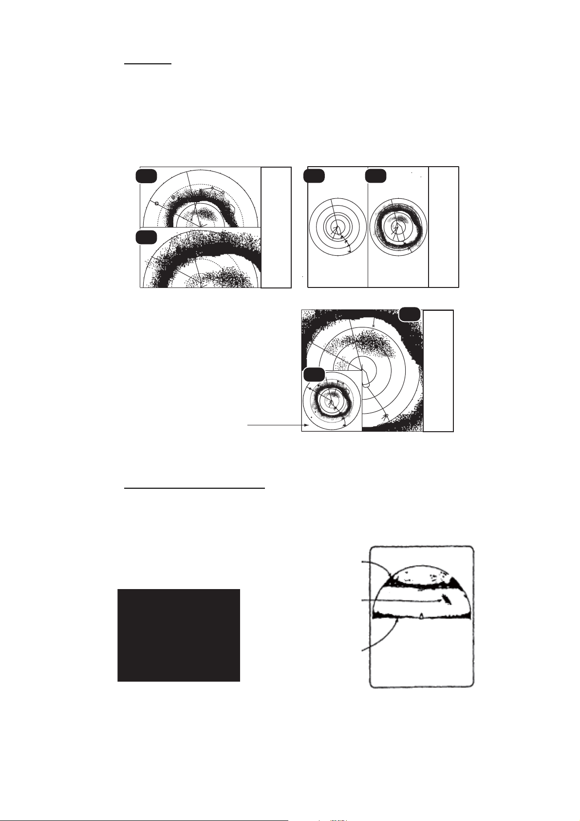
2.4.3 Relation between bottom echo and tilt angle
The figure below illustrates how two schools of fish "a" and "b" are displayed on the
screen using three different tilt angles.
Case 1: Tilt angle 30° to 40°: This tilt angle will display the entire bottom since it is
captured by the full width of the beam. The school of fish is obscured by the bottom.
Case 2: Tilt angle 10° to 20°: This tilt angle will only display half the bottom since it
is captured by only the lower half of the beam. The school of fish is located above the
bottom.
Case 3: Tilt angle 0° to 5°: This tilt angle may or may not capture the bottom since
the returning bottom echo is weak. The school of fish is located close to the bottom.
2. HORIZONTAL MODE
a
a
Case 1
Case 2
a
Case 2
Case 3
b
a
a
a
b
Case 3
Case 1
Points to consider
• Normally, a vertically distributed school of fish is a better sonar target than the bottom, because it reflects the transmitted pulse back toward the transducer.
• In case 3, both schools of fish "a" and "b" are presented. Generally speaking, however, midwater schools of fish tend to be larger than schools of fish on the bottom
and they are often displayed near the bottom on the display.
• It is difficult to detect bottom fish when they are not distributed vertically.
2-7
Page 34

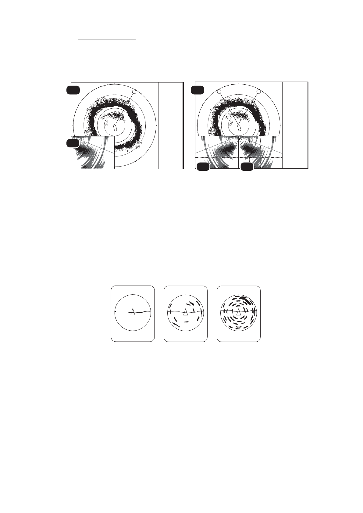
2. HORIZONTAL MODE
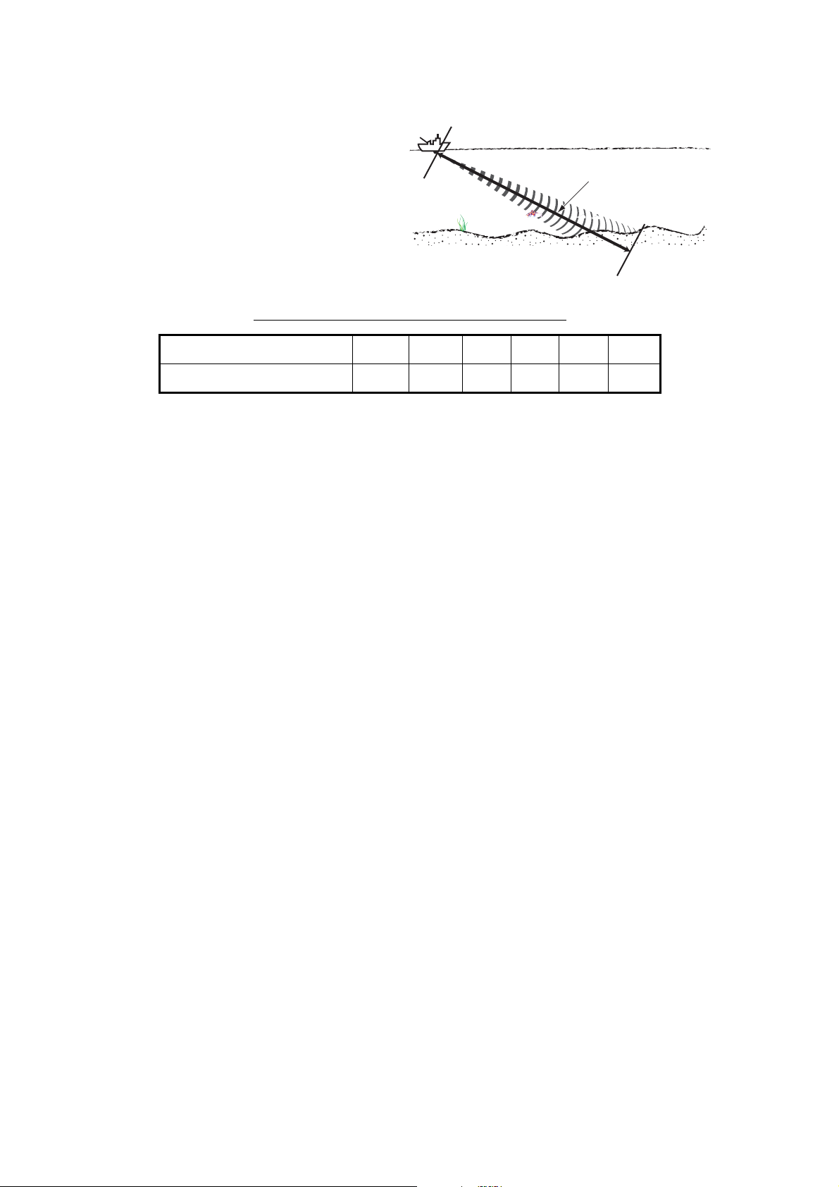
2.4.4 Tilt angle for surface fish
Sound emitted from the sonar transducer forms an oval-shaped beam with a width of
approximately 10° in the vertical direction (vertical beam width at -6dB). The tilt angle
indicates the angle between the centerline of the beam and the horizontal plane. Then,
if the tilt angle is set to 0°, the centerline is parallel with the sea surface and one half
of the emitted sound goes upward, toward the sea surface.
This causes one half of the emitted sound to be reflected toward the transducer and
displayed on the screen as sea surface reflections. When the sea is calm, since the
sound is reflected just like a light hitting a mirror at a low incident angle, it propagates
away and the sea surface reflections become negligible.
However if the sea is not calm enough, they will become dominant and interfere with
observation of wanted echoes. To minimize these sea surface reflections and to
search for schools of fish on the surface effectively, the tilt angle is usually set between
4° and 5° so the upper portion of the beam becomes almost parallel with the sea surface. When the sea is rough, the tilt angle is slightly increased to lessen the affect of
sea surface reflections.
Sea surface
Tilt angle 0°
10°
Sea surface
Tilt angle 4-5°
10°
2.4.5 Suitable tilt angle
The figure below illustrates the relationship among tilt angle, depth and detection
range. Refer to it to find out the suitable tilt angle for a given depth/detection range.
Tilt angle setting: relationship between tilt angle and detection range
100
(200)
20(40)
40(80)
60(120)
80(160)
100(200)
Depth (m)
200
(400)
300
(600)
400
(800)
Range(m)
Tilt 0°
(0°-5°)
Tilt 5°
(0°-10°)
Tilt 10°
(5°-15°)
In grey
Tilt 15°
(10°-20°)
200(400)
Vertical width of sonar beam
10°
2-8
100 m100 m
17 m
200 m
35 m
300 m
(-6dB)
52 m
Page 35
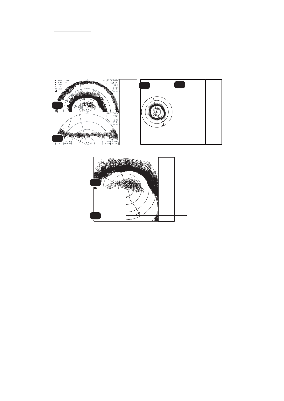
2. HORIZONTAL MODE
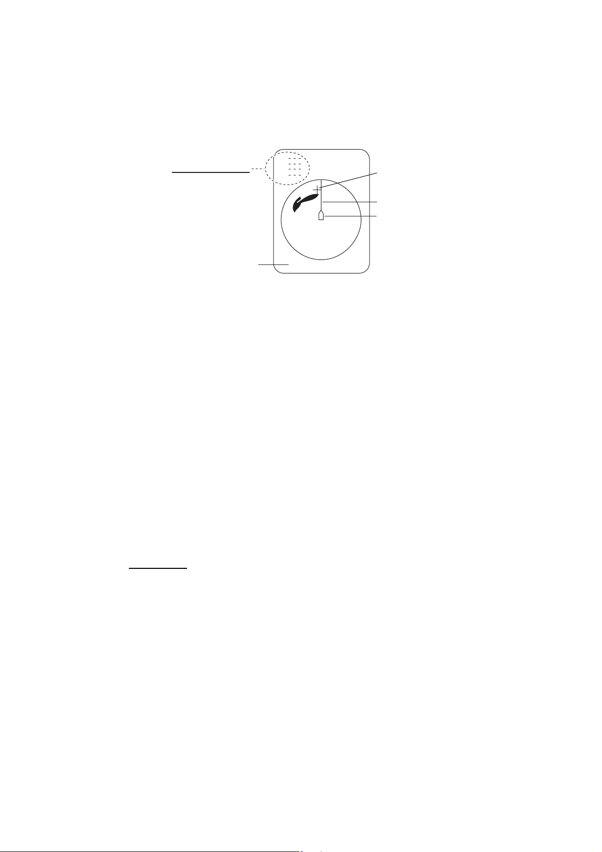
2.5 How to Measure Range and Bearing to a Target
Operate the trackball to place the cursor on the target you want to measure the range
and bearing. The range, bearing and depth to the target appear at the upper left corner
of the screen.
TRACKBALL DATA
Slant range
Horizontal range
Depth
B Relative or
True bearing
㪙
Cursor
Heading line
Own ship mark
Cursor L/L position
㩷㩷㩷㩷㪊㪋°㪌㪍㪅㪎㪏㪐㪥
㪈㪉㪊°㪋㪌㪅㪍㪎㪏㪜
Note 1: Trackball position may also be shown in latitude and longitude. For further details, see "Cursor Position" on page 7-12.
Note 2: The bearing display is available in four formats. See "Other Marks" on page 7-
12.
2.6 How to Eliminate Weak Echoes
Echoes from targets such as bottom and fish return to the transducer in order of distance to them, and when we compare their intensities at the transducer face, those
from nearer targets are generally stronger due to little propagation attenuation and little absorption. If these echoes are displayed directly on the screen, the size of the displayed echo from the same school of fish may change with distance, making it difficult
to judge the actual size of the school of fish. To overcome this inconvenience use the
TVG curve function. This function compensates for propagation loss of sound in water;
amplification of echoes on short range is suppressed and gradually increased as
range increases so that similar targets are displayed in the similar intensities irrespective of the ranges to them.
TVG curve
Four TVG curves are available and they vary the gain from large to small.
1. Press the MENU/ESC key to open the main menu.
2. Select the [Gain Setting] menu then push the left-click button.
2-9
Page 36

2. HORIZONTAL MODE
3. Press the H/V/S key to select [H1] or [H2] tab.
4. Select [Sel TVG Curve] then left-click.
5. Select a TVG curve then push the left-click button.
The smaller the number, the gentler the gain change over distance.
6. Select [Quit] on the setting box then push the left-click button.
7. Long-press the MENU/ESC key to close all menus.
The TVG is also used to suppress unwanted echoes (sea surface reflections, cruising
noise, etc.) on near ranges. If the selected curve does not provide satisfactory results,
try to adjust [TVG-Near], [TVG-Medium] or [TVG-Far], as shown below.
TVG distance and setting
This sonar has three TVG
functions, NEAR, MEDIUM
and FAR, and they mainly
compensate for propagation
Near
Approx. 100 m
Approx. 400 m
Med
loss on short, middle and long
ranges respectively, centered
Far
Approx. 800 m
at the ranges shown below.
The higher the TVG setting,
the greater the amplification
of echoes.
1. Press the MENU/ESC key then push the left-click button to open the main menu.
2-10
2. Select [Gain Setting] then push the left-click button.
3. Press the H/V/S key to select [H1] or [H2] tab.
Page 37

4. Select [TVG Distance] then push the left-click button.
5. Select [Changeable] then push the left-click button.
Current settings
6. Select [Near], [Med] or [Far] as appropriate then push the left-click button to
change the setting.
Near: Setting range, 50 - 150 m, 10 m increments. Med: Setting range, 300 - 500
m, 20 m increments Far: Setting range, 600 - 1000 m, 40 m increments
7. Select [Quit] on the setting box then push the left-click button.
Adjust the TVG level for selected TVG distance as follows.
2. HORIZONTAL MODE
Select item with trackball;
push left-click button to adjust.
8. Select [TVG-Near], [TVG-Med] or [TVG-Far] as appropriate then push the leftclick button.
9. Select S or T as appropriate then push the left-click button to change the setting.
The setting range is -5 to 5. The higher the setting value, the higher the gain. For
strong echoes such as sea surface reflections or plankton layer lower the setting
by 1 or 2.
10. Select [Quit] on the setting box then push the left-click button.
11. Long-press the MENU/ESC key to close all menus.
Note: When a school of fish is located on a long-range setting (about 800 meters)
and is approaching own ship do as follows:
1) Adjust the tilt to keep the school of fish in the center of the sonar beam, name-
ly, the school of fish is displayed in strongest colors possible.
2) Confirm that the fish echo is displayed in the same color as it approaches.
3) If the color suddenly changes to weaker colors as the fish enters MEDIUM and
NEAR areas, the TVG is improperly set. Adjust the TVG.
4) If this setting produces sea surface reflections and noise, try to remove them
with the AGC (section 2.7.1) and noise limiter (section 2.9.5).
Absorption coefficent
Attenuation of the acoustic pulse underwater varies with sea area and water temperature. This absorption can be compensated by adjusting the absorption coefficient. In
most cases, no adjustment is necessary. If sensitivity decreases with distance, increase the absorption coefficient setting. And if it increases with distance decrease
this setting.
2-11
Page 38

2. HORIZONTAL MODE
2.7 How to Adjust Strong, Weak Echoes
2.7.1 AGC
The AGC function automatically reduces the receiver gain only against strong echoes
such as the bottom or a large school of fish. Since the AGC function does not affect
weak echoes, a small school of fish becomes easier to detect. Adjust it so that the
AGC works only on bottom reflections. Do not set it too high; weak echoes may be
missed.
1. Press the MENU/ESC key to show the main menu.
2. Select the [Gain Setting] then push the left-click button.
3. Press the H/V/S key to select [H1] or [H2].
4. Select [AGC] then push the left-click button to show the setting box.
5. Select S or T then push the left-click box to change the setting.
The setting range is -20 to 20. The higher the setting, the higher the degree of suppression.
6. Select [Quit] on the setting box then push the left-click button to close the box.
7. Long-press the MENU/ESC key to close all menus.
2.7.2 Near AGC
When the water is shallow or heavily sedimented, the unwanted and scattered echoes
from close-in may be excessively strong. In this case, a school of fish which is displayed at between 300 and 500 m may disappear gradually when the ship starts approaching the school of fish.
Use the Near AGC feature to suppress this strong echo. Normally set it between 3 and
4, however, this setting depends on the sea condition. Do not set it too high; all echoes
(including noise) from near distance may be painted in red.
1. Press the MENU/ESC key to show the main menu.
2. Select the [Gain Setting] then push the left-click button.
3. Press the H/V/S key to select [H1] or [H2] tab.
4. Select [Near AGC] then push the left-click
button to show the setting box.
5. Select S or T then push the left-click button to change the setting.
The setting range is -20 to 20. The higher
the setting, the stronger the echo level on
near range.
2-12
6. Select [Quit] on the setting box then push the left-click button to close the box.
7. Long-press the MENU/ESC key to close all menus.
Note: The range which Near AGC covers is set at [Near AGC Distance] in the [Near
AGC] menu. The setting range is 20 to 200 m (20 m step). The setting range can be
changed. For details, contact your dealer.
Page 39

2.7.3 2nd AGC
While it is ideal to suppress bottom echoes with the AGC alone there are some fishing
grounds where this is not possible. (The high power sonar has the advantage of longrange detection but this can also be a disadvantage, since weaker echoes may be hidden in strong, unwanted echoes such as the bottom.) If you cannot suppress bottom
echoes or sea surface reflections by the AGC function alone, use the 2ND AGC feature. Normally a setting of 1 or 2 is suitable. For especially strong echoes, use a setting
of 3 or 4.
1. Press the MENU/ESC key to show the main menu.
2. Select [Gain Setting] then push the left-click box.
3. Press the H/V/S key to select the [H1] or [H2] tab.
4. Select [2nd AGC] then push left-click button.
5. Select [2nd AGC] again then push the left-click button.
2. HORIZONTAL MODE
6. Select S or T then push the left-click button to change the setting.
The setting range is 0 to 20. The higher the setting, the stronger the suppression
on long range.
7. Select [Quit] on the setting box then push the left-click button to close the box.
8. Long-press the MENU/ESC key to close all menus.
Other AGC-related items on the [2ND AGC] menu
Distance: Set the start range for the 2nd AGC. The setting range is 0 - 2000 m, in 20
m increments. 2nd AGC is inoperative if the display range is lower than the 2nd AGC
start range.
Type: Select the TVG type for 2nd AGC. Select [Normal] for everyday use.
Post 2nd AGC-Near*: Set the near range threshold for [Post 2nd AGC]. The larger
the figure, the greater the suppression.
Post 2nd AGC-Far*: Set the far range threshold for [Post 2nd AGC]. The larger the
figure, the greater the suppression.
Post 2nd AGC-Dist*: Switch between Far and Near Post 2nd AGC.
2-13
Page 40

2. HORIZONTAL MODE
Exclusive Rng S: This feature prevents use of
the 2nd AGC, Post 2nd AGC in a certain area at
the stern, where unwanted echoes (such as
screw noise) can interfere with the 2ND AGC or
Post 2nd AGC feature. Set the area of exclusion
on the setting dialog box. In the example at right
the area of exclusion is ±45°.
*The [Post 2nd AGC] functions independently of
[2nd AGC]. If the [2nd AGC] cannot suppress the bottom echo or sea surface reflections, try to suppress them with the [Post 2nd AGC]. For particularly strong echoes
raise the AGC setting.
2.7.4 How to shorten pulse length
The pulse length determines the length of the transmission pulse emitted into the water. While a longer pulse is advantageous for long-range sounding, it has the disadvantage of being poor in discrimination of targets, that is, the ability to separate several
closely located targets. When searching bottom fish, therefore, it is useful to shorten
the pulse length in order to separate fish echoes from bottom reflections.
-45°
Area of
exclusion
+45°
Note: For search of surface and midwater fish in which bottom reflections are not so
strong, use the longest pulse length "9".
1. Press the MENU/ESC key to show the main menu.
2. Select [TX/RX Setting] then push the leftclick button.
3. Press the H/V/S key to select [H1] or [H2]
tab.
4. Select [TX Pulse Length] then push the leftclick button.
5. Select S or T then push the left-click button to change the setting. The setting range
is 0-9. The higher the setting, the longer the
pulse length.
6. Select [Quit] on the setting box then push the left-click button to close the box.
7. Long-press the MENU/ESC key to close all menus.
2-14
Page 41

2. HORIZONTAL MODE
2.8 How to Suppress Bottom and Sea Surface Reflections in Shallow Waters
In shallow fishing grounds with hard or rocky bottom, bottom reflections often interfere
with wanted fish echoes and they can not be eliminated sufficiently with the aforementioned TVG and AGC functions, especially when the Tilt is set to a larger angle in order
to track schools of fish approaching within 400 m. In such cases try to reduce the output power by adjusting the Tx power instead of turning down the gain. The picture becomes clearer when the output power is reduced rather than when the GAIN is
decreased as illustrated below.
INCORRECT
METHOD
CORRECT
METHOD
1. Press the MENU/ESC key to show the main menu.
2. Select [TX/RX Setting] then push the left-click button.
3. Press the H/V/S key to select [H1] or [H2] tab.
Fish echo
TVG and AGC
adjusted with
TX POWER kept high
Reduce TX POWER
with GAIN kept
constant
Fish echo
weakened
Fish echo
4. Select [TX Power] then push the left-click button.
5. Select S or T then push the left-click button to change the setting. The setting
range is 0-9. The higher the setting the greater the TX power.
6. Select [Quit] on the setting box then push the left-click button to close the box.
7. Long-press the MENU/ESC key to close all menus.
2-15
Page 42

2. HORIZONTAL MODE
2.9 How to Reject Sonar Interference and Noise
While observing the sonar picture, you may encounter occasional or intermittent noise
and interference. These are mostly caused by on-board electronic equipment, engine
or propeller noise, or electrical noise from other sonars being operated nearby.
2.9.1 How to identify the noise source
To eliminate noise effectively, you should first identify the noise source as follows:
1. Stop transmission on the [Test] menu; turn on [TX]. Turn on the power of all onboard equipment one by one while observing the picture. If noise appears on the
sonar display, that equipment is emitting noise. Check the offending equipment's
ground and installation.
2. Run the boat at various speeds to check if the noise is speed dependent.
If neither of the above two steps has effect on the picture, adjust one of the following:
2.9.2 Change TX interval
When other sonars nearby are operating the same transmission interval
as that of own ship's sonar, rings of
interference appears on the display.
To remove the rings from the screen,
do the following:
1. Press the MENU/ESC key to
show the main menu.
2. Select [TX/RX Setting] then push
the left-click button.
3. Press the H/V/S key to select
[H1] or [H2] tab.
4. Select [TX Interval] then left-click.
5. Select S or T then push the left-click button to change the setting. The setting
range is 0-9. The higher the setting, the longer the TX interval. [EXT KP] is for external KP synchronization; however, adjustment on the System menu is required.
See the installation manual.
6. Select [Quit] on the setting box then push the left-click button to close the box.
Tx interval high Tx interval lowered
Interference
2-16
7. Long-press the MENU/ESC key to close all menus.
Note: When you operate the sonar with the following settings in shallow water, the sea
clutter from the previous transmission may appear in near range. To suppress this
clutter, reduce the [TX Interval] by 2 or 3.
• Range: 60 to 200 m
• TX Pulse setting: 9
Page 43

2.9.3 Interference rejector
This control is similar to the interference rejector on echo sounders and radars. It is
effective for rejecting random noise and sea surface reflections in rough sea conditions. Set it so that noise is just eliminated. Do not use an unnecessarily high setting
since it may also reject small, wanted echoes.
1. Press the MENU/ESC key to show the main menu.
2. Select [Picture Setting] then push the leftclick button.
3. Press the H/V/S key to select the [H1] or
[H2] tab.
4. Select [Int Reject] then push the left-click
button.
5. Select S or T then push the left-click button
to change the setting. The setting range is 0-3. The higher the setting, the greater
the degree of interference rejection.
6. Select [Quit] on the setting box then push the left-click button to close the box.
2. HORIZONTAL MODE
7. Long-press the MENU/ESC key to close all menus.
2.9.4 Shift TX frequency
If the interference cannot be suppressed by the interference rejector or change in TX
interval, shift the TX frequency from the [Frequency] menu.
1. Press the MENU/ESC key to show the main menu.
2. Select [TX/RX Setting] then push the left-click button.
3. Press the H/V/S key to select the [H1] or [H2] tab.
4. Select [Frequency] then push the left-click button.
5. Select [Freq Shift1] then push the left-click button.
6. Select S or T then push the left-click button to change the setting. The setting
range is -65 to 65.
7. Select the [Quit] on the setting box then push the left-click button to close the box.
8. Long-press the MENU/ESC key to close all menus.
Note 1: In some cases the frequency cannot be changed because of operating bandwidth. In this case the frequency setting is grayed.
Note 2: The setting for [Freq Shift2] is valid when [Sidelobe Sup. A] (see
section 2.9.9.) is set between -3 and -1. Set [Freq Shift1] well apart from [Freq Shift2]
to better suppress sidelobes.
2-17
Page 44

2. HORIZONTAL MODE
2.9.5 Noise limiter
Weak, unwanted reflections, colored light-blue or green, appear when the water is
dirty, plankton layers exists, or due to ship’s noise. The noise limiter can reduce the
effects of these unwanted reflections. Raising the setting causes unwanted reflections
to be displayed in colors of blue to background color.
1. Press the MENU/ESC key to show the main menu.
2. Select [Display Setting] then push the left-click button.
3. Press H/V/S key to select the [H1] or [H2] tab.
4. Select [Noise Limiter] then push the left-click button.
5. Select S or T; then push left-click button to change setting. The setting range is
0 to 15. The higher the setting, the higher the degree of the suppression.
6. Select [Quit] then push the left-click button to close the box.
7. Long-press the MENU/ESC key to close all menus.
2-18
Page 45

2.9.6 Reverberation
You may select the length of reverberation for the echo signal, with [Reverberation] on
the [TX/RX Setting] (H1 or H2 tab). The setting range is 0-3. The larger the value, the
lower the reverberation effects. Set the length of reverberation properly to make it easier to see the echo signal.
2.9.7 Echo average
[Echo Average] (H1 or H2 tab) on the [Picture Setting] menu adjusts echo afterglow the amount of time an echo signal remains on the screen. This feature can be useful
for watching echo movement. The setting range is 0-7. Setting between 1 and 3:
Echoes are gradually displayed and afterglow remains on the screen longer as the
setting is increased.Setting between 4 and 7: Echoes are quickly displayed and afterglow remains on the screen longer as the setting is increased.
2.9.8 Reference bearing in frequency shift
The reference bearing in frequency shift can be changed to avoid sonar interference
and noise. If noise or interference appears at a specific bearing, change the value of
the [Freq/Bearing Set] in the [TX/RX Setting] (H1 or H2 tab) - [Frequency] menu. The
setting range is 0°-358° and the default setting is 0°.
2. HORIZONTAL MODE
Note: [Freq/Bearing Set] is valid when [Sidelobe Sup. A] (see paragraph 2.9.9) is selected to other than 0°).
2.9.9 How to suppress sidelobes
False echoes produced by sidelobes may appear on the display depending on the distribution pattern of a school of fish and the positional relationship between it and a marine object (reef, etc.) and wake reverberation. To reduce these sidelobes, use
[Sidelobe Suppress] in the [TX/RX Setting] menu (H1 or H2 tab).
Sidelobe suppression A
Watch the echoes while adjusting the suppression. The setting range is -3 to 4 (0 is
OFF). The larger the setting, the more the sidelobe is suppressed. For greatest suppression, use a negative setting (-3 to -1).
Note: When a negative value is used, [TX/RX Mode] in the [Display Setting] menu is
automatically selected to [Alternative]. See "TX/RX Mode" on page 7-3 for details.
2-19
Page 46

2. HORIZONTAL MODE
Sidelobe suppression B
For greater sidelobe suppression,
use [Sidelobe Sup. B]. The setting
range is 1 to 5. The larger the setting
value, the more the sidelobe is suppressed; however, the width of the
beam increases thus resolution is
lower. The negative value setting (-5
to -1) is effective for reducing the effects of screw noise.
The area in which to suppress sidelobes with [Sidelobe Sup. B] can be
set with [Sidelobe Dir1] and [Sidelobe Dir2]. The setting range is 0°≤ [Sidelobe Dir1]
≤
[Sidelobe Dir2] ≤180°, symmetrical in port-starboard directions. An area can be set
when [Sidelobe Sup. B] is 0 - 5. In this case the settings of Dir1 and Dir2 are gray.
2.10 How to Adjust Beam Width
Area in which SIDELOBE
SUP. B works (portstarboard symmetrical)
Sidelobe bearing 1
Sidelobe bearing 2
Echo from screw
noise
The width of the horizontal beam can be adjusted from the [Beam Width] menu.
1. Press the MENU/ESC key to show the main menu.
2. Select [TX/RX Setting] then push the left-click button.
3. Press the H/V/S key to select the [H1] or [H2] tab.
4. Select [Beam Width] then push the left-click button.
5. Select the item to adjust then push the left-click button.
2-20
Page 47

2. HORIZONTAL MODE
Description of Beam Width menu
Beam Control: Control the beamwidth according to option selected. Manual: Se-
lect this item to enable adjustment of the other items in this menu. Range: The
beamwidth is automatically controlled with the range setting. Tilt: The beamwidth
is automatically widened as tilt goes deep. This is convenient for keeping a watch
on fish that ascend and descend.
TX Beam Width*: Increase the value to display close-range echoes clearly.
Hor. RX Beam Width*: Increase the value to improve horizontal resolution.
Ver. RX Beam Width*: Increase the value to improve vertical resolution to distin-
guish fish echoes from bottom echoes.
RX Beam Control: Increase the value to improve horizontal resolution.
Note: When [RX Beam Control] is set to 1 - 3 and [Sidelobe Sup. B] is set to other
than 0, [TX/RX Mode] on the [Display Setting] menu is automatically selected to
[Alternative]. See "TX/RX Mode" on page 7-3.
*: Available only when [Beam Control] is set to [Manual].
6. Select [Quit] on the setting box then push the left-click button to close the box.
7. Long-press the MENU/ESC key to close all menus.
2.11 How to Track a School of Fish
The target lock function automatically tracks a school of fish so you will not lose sight
of it on the display. Two types of target lock are available: position tracking and tracking of school of fish. Select one from the menu as shown in the procedure that follows.
The default setting is tracking of school of fish. Speed and bearing data are required.The FSV-85 cannot track a school of fish if the level of the echo is too weak.
Track of
school of fish*
* [FISH] mode
TARGET LOCK MARK
One target lock mark is shown. For the Horizontal 2 and Slant combination displays,
the mark is shown on the applicable display. The target lock mark does not appear on
the displays where it can not be inscribed.
Vector
Length: Speed of movement
Direction: Direction of movement
2.11.1 How to select the target lock mode
1. Press the MENU/ESC key to show the main menu.
2. Select [Others] then push the left-click button.
3. Select [Initial Setting] then push the left-click button.
4. Select [Changeable] then push the left-click button.
2-21
Page 48

2. HORIZONTAL MODE
5. Select [Target Lock] then push the left-click button.
6. Select [Tracking Method] then push the left-click button.
7. Select [Fish] or [Target Mark] then push the left-click button.
See paragraph 2.11.2 and paragraph 2.11.3.
8. Select [Quit] on the setting box then push the left-click button to
close the box.
9. Long-press the MENU/ESC key to close all menus.
2.11.2 Fish mode
The automatic echo target lock function automatically tracks the operator-selected
school of fish. When [TILT INTERLOCK] on the [TARGET LOCK] menu (previous
page) is set to [TILT & RANGE], and the tracked school of fish goes out of the zone in
the range direction, the range and tilt are automatically controlled according to the position of the school of fish.
1. Select [Fish] in the procedure in section 2.11.1.
2. On the horizontal display, use the trackball to select the school of fish to track.
3. Press the TARGET LOCK key.
The target lock mark (white) with vector is put on the school of fish. The vector
shows the speed and direction of movement of the school of fish. The tip of the
vector is the estimated position of the school of fish when the vector time elapses.
The target lock mark appears on the vertical display, however the vector is not
shown.
2-22
Page 49

If the target is lost, the target lock mark changes to red color and the tracking
mode changes to position mode (see next section) at that position. When the sonar detects and tracks the target again, the FISH mode is restored.
4. To disable the target lock, press the TARGET LOCK key.
2.11.3 Target mark mode
Target lock mark
Track of school of fish
(Turned ON or OFF on
Mark Display menu.)
TARGET LOCK DATA
2975m (Horizontal range)
153m (Depth)
S
12.3kn (Speed)
C
Vector
(Heading data required)
256° (Course)
2. HORIZONTAL MODE
This mode tracks a stationary position (such as a reef) using position data fed from a
navigator.
AB CD
Depth
E
1. Select [Target Mark] in the procedure in section 2.11.1.
2. On the horizontal display, use the trackball to select the location to track.
3. Press the TARGET LOCK key.
Tilt, range and vertical bearing are automatically adjusted to track the location. Using the figure above as an example, the target lock mark is placed on location E.
Then, the equipment remembers the location of E and automatically changes the
tilt angle as the ship moves from position A through D. As long as the school of
fish E is stationary its echo is kept displayed on the screen.
4. To disable the target lock, press the TARGET LOCK key.
2.11.4 Target lock menu description
Target lock functions not previously mentioned are described below.
Tilt Interlock: Provides automatic change of tilt angle and range or tilt angle in target
lock. (Setting options: [OFF], [Tilt], [Tilt&Range])
Mark Interlock: Turns numeric/graphic data displays ON/OFF in target lock. [Off]
turns off both the estimate mark 1, 2 histogram and data display. [Estimate Mark] enables the estimate mark 1, 2 histogram. [Est & Fish Info] enables the both the estimate
mark 1, 2 histogram and data display.
2-23
Page 50

2. HORIZONTAL MODE
Tracking Data: Selects which target lock tracking data to use, horizontal or slant, or
both horizontal and vertical.
Threshold: Selects the minimum signal level to use in target lock tracking. The setting
range is 1 to 30. Target lock tracks a target whose signal level is greater than set here.
Bottom Threshold: When a target is judged as a bottom echo, raise this setting to
differentiate bottom from target. The setting range is 0 to 5.
Target Speed Limit: Sets maximum fish speed to track. The setting range is 1kn to
15kn.
Smoothing: Sets smoothing rate for fish speed data. The higher the figure, the
smoother the position of the target lock target. Avoid oversmoothing, to prevent delay
in tracking when own ship or target moves suddenly. The setting range is 0.0 to 1.0.
Target SPD Update: Sets the interval at which fish speed data is updated. The intervals are 15, 30, 45 and 60 seconds.
Target Lock Window: Selects the size of target lock detection area; normal, large,
largest. (The area is not indicated on the screen.)
Dimension Setup: Sets dimension constant for calculation of weight (ton) of school
of fish from the dimension of the school of fish.
Volume Setup: Sets volume constant for calculation of weight (ton) of school of fish
volume.
2.12 Presentation Mode
2.12.1 Presentation mode description
This sonar has four presentation modes, head-up, north-up, course-up and true motion. Select one with [Presentation Mode] in the [Others] - [Display Setting] menu.
㪜㪆㪪
㪥
Head-up
N N
N
North-up True Motion
Course-up
2-24
Head-up: The display is oriented toward ship’s heading. The heading direction ap-
pears at the top of the display. Own ship position is fixed at the screen center. Echoes
from fish and the bottom move on the screen relative to own ship’s movement. This
mode is useful for general use.
North-up: The display is oriented so North is at the top of the screen. Own ship position is fixed at the screen center and own ship mark pivots with ship’s movement. Echoes from fish and the bottom move on the screen relative to own ship’s movement.
Course-up: The display is oriented according to course. Own ship position is fixed at
the screen center. Echoes from fish and the bottom move on the screen relative to
own ship’s movement. Targets are displayed at ship’s bow.
Page 51

2. HORIZONTAL MODE
True Motion: Stationary objects are fixed and own ship and fish echoes move on the
display in accordance with their true courses and speeds. Thus you can observe own
ship and fish echo movement with respect to the bottom. This mode requires speed
and heading data. When own ship mark reaches an edge of the off-center effective
area it is automatically returned to the screen center as below.
NN
Offcenter
effective area
(a) Own ship mark reaches
an edge of offcenter
effective area
(b) Own ship mark is
automatically returned to
screen center
Automatic return of own ship mark in true motion
2.12.2 How to select a presentation mode
1. Press the MENU/ESC key to show the main menu.
2. Select [Others] then push the left-click button.
3. Select [Display Setting] then push the left-click button.
4. Select [Presentation Mode] then push the left-click button.
5. Select desired mode then push the left-click button.
6. Select [Quit] on the setting box then push the left-click button to close the box.
7. Long-press the MENU/ESC key to close all menus.
Note: The true motion display range may be set to 1.3 to 1.6 times the range with [TM
Disp Range] on the [Display Setting] menu.
2-25
Page 52

2. HORIZONTAL MODE
2.13 How to Detect Schools of Fish Aurally
Sometimes you may be preoccupied with other tasks and unable to concentrate on
watching the sonar picture. In such cases it would be a good choice to use the audio
function. This function enables you to monitor echoes from schools of fish and bottom
through the external speaker.
2.13.1 How to set the bearing
In the default setting, the audio function is on and the audio sector is 30°.
1. Operate the trackball to place the cursor on the direction you want to monitor
through the speaker.
2. Press the R/B AUDIO key.
The monitoring section is set on the bearing selected, in a 30°, 60°, 90°, 180° or 330°
sector centering the audio bearing mark. Echoes are monitored through the speaker.
Monitoring section
A
Audio bearing mark
Range marker
R 400m
B 45°
Data for range and audio
bearing marks
Note: To erase the range mark and the data at the bottom of the screen, put the cursor
near own ship mark and press the R/B AUDIO key. Note that the audio bearing is
erased when [Audio] on the [Alarm & Audio] menu is turned off.
2.13.2 How to select the audio sector
Select the audio sector as follows. Note that you cannot see this sector on the display.
1. Press the MENU/ESC key to show the main menu.
2. Select [Others] then push the left-click button.
3. Select [Alarm & Audio] then push the left-click button.
*
* In target lock, the audio
bearing mark follows
tracked target.
2-26
Page 53

4. Select [Audio Sector] then push the left click button.
r
5. Select desired sector then push the left-click.
6. Select [Quit] on the setting box then push the left-click button
to close the box.
7. Long-press the MENU/ESC key to close all menus.
2.13.3 Automatic training
You may automatically scan the audio sector and audio bearing
mark in the sector of 12°, 24° or 36° as shown below.
1. First activate the range and audio bearing marks with the R/B AUDIO key.
2. While pressing and holding down the AUTO TRAIN key, press the R/B AUDIO
key to select desired auto train sector among 12°, 24° or 36°, or OFF to disable
automatic training.
Watch the auto train mark to know the currently selected sector. The chosen sector appears in large characters for five seconds at the top of the screen.
2. HORIZONTAL MODE
Auto train mark
A
Note: Select [Off] at step 2 to stop the training.
Auto train secto
Audio bearing
mark
2.13.4 Reverberation for audio signal
You may choose the length of reverberation of the audio signal, with [Reverberation]
on the [Alarm & Audio] menu. The larger the value the longer the reverberation, which
makes it easier to hear the audio signal. The setting range is 0-9 and the default setting is 0.
2.14 Fish Alarm
The fish alarm sounds the aural alarm when a fish echo above a preset strength enters
the operator-set alarm zone.
1. Press the MENU/ESC key to show the main menu.
2. Select [Others] then push the left-click button.
3. Select [Alarm & Audio] then push the left-click button.
4. Select [Fish Alarm] then push the left-click button.
5. Select [ON] then push the left-click button.
6. Select [Quit] from the setting box then left-click to close the box.
7. Select [Alarm Zone] then push the left-click button.
2-27
Page 54

2. HORIZONTAL MODE
8. Operate the trackball to place the cursor on the starting point of the alarm zone.
9. Push the left-click button.
10. Rotate the trackball clockwise to select the ending point. The display paints a fanshaped alarm zone.
The alarm range appears on the display as shown below.
<< Alarm Zone >>
Move trackball cursor to origin of
alarm zone and left click.
Press [R/B] key or right click to cancel.
<< Alarm Zone >>
Move cursor to the end of alarm
range and left click.
Press [R/B] key or right click to cancel.
Fish alarm range
11. Push the left-click button.
12. Long-press the MENU/ESC key to close all menus.
When a fish echo enters the alarm area the buzzer sounds.
Note 1: There must be at least three degrees difference between the starting and ending points to get a fan-shaped alarm zone as shown in (a) and (b) below. Otherwise,
the unit paints a 360-degree alarm zone as in (c) where there is less than 3 degrees
between the starting and ending points.
More than 3°
(a) (b) (c)
Within 3°
Note 2: The echo strength which triggers the alarm can be set with [Alarm Level] on
the [Alarm & Audio] menu. The setting range is 0-30. This value corresponds with the
32-echo colors.
To disable the alarm, select [OFF] at the step 5.
2.15 How to Relocate a School of Fish
The offcenter feature relocates a school of fish.
1. Operate the trackball to place the cursor on the position where you want to relocate the own ship mark.
2. Press the OFF CENTER key.
2-28
Page 55

2. HORIZONTAL MODE
2
3. To move the own ship mark back to the screen center, press the OFF CENTER
key again.
School of fish
School of fish
Press OFF CENTER key
Own ship mark
Set cursor here,
for example,
Note: You can also move the display by long-pressing the left-click button. To restore
the normal display, long-press the right-click button.
Own ship mark moves to
trackball position,
2.16 How to Compare Concentration of School of Fish
2.16.1 How to compare with the fish estimate mark
You can get an estimate of the volume of two schools of fish by using the two ESTIMATE keys as follows:
1. Operate the trackball to place the cursor on a school of fish, and then press the
ESTIMATE 1 key.
The estimate mark 1 appears on the school of fish. Relative volume is shown by
a figure between 0 and 100, below the estimate mark. When the area inside the
mark is filled in reddish brown, volume figure is said to be 100. When the estimate
mark is entered, a graph is shown at the histogram on the numeric/ graphic data
display.
2. Operate the trackball to place the cursor on another school of fish, and then press
the ESTIMATE 2 key.
Compare estimate figures for each school of fish by observing estimate mark data
and the fish histogram.
3. To turn off the estimate marks press their respective keys.
1
25
5
Note: The fish school mark and event mark 1 can be entered with the fish estimate
mark. For details, contact your dealer.
Estimate mark 1
North mark
Relative fish volume
2
65
Estimate mark 2
2-29
Page 56

2. HORIZONTAL MODE
Fish histogram
The fish histogram shows, in graph form, signal strength distribution for the school(s)
of fish marked with an estimate mark on the horizontal/slant displays. The histogram
display for each of those displays will be different since the calculation method is different. This data appears only when an estimate mark is active. When two estimate
marks are active, histograms are displayed one on top of the other as below.
The horizontal axis shows signal strength in 16 colors, and the vertical axis shows the
concentration of a school of fish inside the fish estimate mark. For the fish estimate
mark inscribed on the horizontal display (or slant display) the graph shows the average movement in five scans, to increase accuracy.
2 1
Scan1
Fish estimate
mark source
Fish estimate
mark no.
2
Scan1
Scan2
Fish estimate
mark source
Estimate mark 1 or estimate
mark 2 displayed
Both estimate marks displayed
Note: The histogram display is redrawn five transmissions after a fish estimate mark
is erased and another mark of the same number is entered soon after.
2.16.2 How to compare with the circle cursor
You can get an estimate of the volume of two schools of fish with the circle cursor as
follows:
1. Push the scrollwheel to show the [Select Mark] window.
Selected mark name
Circle cursor
2-30
Scan mode in which mark can be entered
Page 57

2. HORIZONTAL MODE
2. Select the circle cursor and push the left-click button.
The [Select Mark] window disappears, then the cursor is changed to the circle cursor.
㪏㪊㫄
Diameter of the circle cursor
3. Place the circle cursor on a school of fish.
4. Rotate the scrollwheel to adjust the size of the circle cursor.
Set the school of fish in the circle cursor to estimate correctly. The diameter of the
circle cursor is displayed below the circle cursor.
5. Place the circle cursor on another school of fish to estimate the volume.
You can compare the volume of two schools of fish with the diameter of the school
of fish.
6. Push the right-click to quit the measurement.
The circle cursor is changed to the normal cursor.
Note: The event mark 1, event mark 2, fish mark, target lock mark, estimate mark 1,
and estimate mark 2 can be entered from the [Select Mark] window. Push the left-click
button to enter the mark.
2-31
Page 58

2. HORIZONTAL MODE
2.17 How to Measure the Speed of a School of Fish
To ensure a good haul, it is important to estimate the direction and speed of the school
of fish before shooting the net. You can do this with the FISH key. With tidal current
data and fish speed data, you can determine the timing of the net shooting more efficiently. This function requires speed and heading data.
2.17.1 How to measure the speed of a school of fish
1. Place the cursor on the center of a school of fish then press the FISH key or push
the left-click button. The latest fish mark ( ) appears on the school of fish.
2. Wait until the target fish moves a reasonable distance from the latest fish mark.
3. Place the cursor on the same school of fish selected in step 1 then press the FISH
key.
The latest fish mark appears on the target, the 2nd latest fish mark ( ) appears
on the location selected at step 1 and any earlier fish marks are shown with an X.
The distance between the two fish marks and speed, course, and bearing of the
school of fish appear at the bottom right-hand corner of the horizontal display area.
Latest fish mark
Place the cursor
on a school of fish and
press [FISH] key.
Note 1: The time and distance between each press of the FISH key should be as
long as possible to increase accuracy of measurement. For best results, repeat
the procedure two or three times.
Note 2: Each time the FISH key is pressed the latest fish mark and ship's speed
mark change in the sequence shown below. A maximum of 20 fish marks can be
entered. When you enter more than 20, the earliest fish mark is erased.
WAIT A FEW
MINUTES
2nd latest fish mark
X
Place the cursor
on the school of fish’s
current location and press
[FISH] key again.
This data is the latest fish
mark data.
Latest fish mark
Earlier fish mark (Max. 18)
FISH MOVEMENT DATA
(Distance moved)
2975m
S 12.3kn (Speed)
CB256° (Course)
(Horizontal range to fish mark)
153m (Depth)
°
(Bearing)
235
2-32
[FISH]
key pressed once
twice
three times
four times
Page 59

2.17.2 How to delete fish marks
Fish marks can be deleted individually with the DELETE MARK key or by earliest entry from the menu.
How to delete fish marks with the DELETE MARK key
Use the trackball to place the cursor on the fish mark you want to erase. The color of
the fish mark changes from white to red when the fish mark is correctly selected. Press
the DELETE MARK key to delete the fish mark.
How to delete fish marks from the menu
1. Push the right-click button on the numeric/graphic data display to show the popup menu.
2. Select [Erase Marks] then push the left-click button.
2. HORIZONTAL MODE
3. Select [Fish Mark] then push the left-click button. Each push of the left-click button
deletes the earliest fish mark.
4. Long-press the MENU/ESC key to close all menus.
Note: The default function of the F5 key deletes the earliest fish mark.
2-33
Page 60

2. HORIZONTAL MODE
2.18 Event Mark, Own Ship Position Mark
The event mark is useful for finding the horizontal range, depth and bearing to a location some distance from current position. 20 such marks may be inscribed on the horizontal display. This function requires speed and heading data.
There are two types of event marks, latest event mark 1 ( ) and event mark 2 ( ).
Each time an event mark is entered the latest event mark appears at the cursor posi-
tion and all other event marks are shown by marks and numbered in sequential
order. When the memory capacity for event marks is reached the earliest event mark
is automatically erased to make room for the latest.
2.18.1 How to enter an event mark
1. Set the cursor where you want to place an event mark.
2. Press an EVENT key. The horizontal range, depth and bearing to the event mark
appear at the bottom left corner of the horizontal display area. The event mark 1
can be entered by pushing the right-click button.
,
234m: Horizontal range (m) from own ship mark
19m: Present depth (m) to mark
(35m): Depth (m) of mark at moment EVENT key is pressed.
B 265°: Present bearing (degree)
Bottom left-hand corner of the screen
Ex. Indications when the EVENT key is pressed
With speed and heading data the mark follows own ship’s movements. In the True Motion mode, the event mark is stationary. When the tilt angle is changed mark position
changes with slant range. Note however that the mark’s position does not change
when automatic tilt is active; the tilt center angle is used to position the mark.
Plotting an event mark on the display is equivalent to dropping a buoy with an anchoring chain that extends from surface to bottom. The buoy is fixed at its geographical
location, but the marker on the display moves to a point where the present beam plane
intersects the anchor chain of the buoy as the ship moves or the tilt angle is changed.
This can be said about marks as well such as fish mark and cursor.
2-34
You observe picture from
direction of mark.
(35)
B
A
Stored when
EVENT key is
pressed.
Page 61

2. HORIZONTAL MODE
2.18.2 How to enter an own ship position mark
Place the cursor close to the center of the own ship mark (U) and press the EVENT
key. Ten own ship position marks may be inscribed. When the capacity for own ship
position marks is reached the earliest own ship position mark is automatically erased.
Note: The SHOOT key can enter the own ship position mark. Set [Event Key] to
[Shoot] on the [Mark Display] menu.
2.18.3 How to erase an event mark, own ship position mark
Event marks and own ship position marks can be deleted individually with the DELETE MARK key or by earliest entry from the menu.
Delete an event mark, own ship position mark with MARK DELETE key
Use the trackball to place the cursor on the event mark or own ship position mark you
want to erase. The color of the mark changes from white to red when the mark is correctly selected. Press the DELETE MARK key to delete the mark.
Delete an event mark, own ship position mark from the menu
1. Push the right-click button on the numeric/graphic data display to show the popup menu.
2. Select [Erase Marks] then push the left-click button.
3. Select [Event Mark1], [Event Mark2] or [Own Ship Pos Mark] then push the leftclick button.
Each push of the left-click button deletes the oldest event mark or own ship mark.
4. Long-press the MENU/ESC key to close all menus.
Note: The default function of the F3 (for event mark 1), F4 (for event mark 2) and F6
(own ship position) keys delete the oldest event mark or own ship mark.
2-35
Page 62

2. HORIZONTAL MODE
2.19 Net Course Mark
Before shooting the net, decide the shoot timing considering tide direction, distance to
the school of fish and moving direction of the school of fish. Use the net course mark
as a guide to decide the timing. This function requires speed and heading data.
How to enter the net course mark
1. Press the MENU/ESC key to show the main menu.
2. Select [Others] then push the left-click button.
3. Select the [Display Setting] then push the left-click button.
4. Select the [Net Course Mark] then push the left-click button.
Net course mark
<<Set net course mark>>
Move trackball cursor to net course mark
position and left click.
Press R/B key to cancel.
5. Use the trackball to position the net course mark, which is shown by a dashed circle.
6. Push the left-click button to set, and the dashed circle changes to a solid one.
7. Long-press the MENU/ESC key to close all menus.
Note 1: To delete the net course mark select [Delete] at step 4.
Note 2: The default function of the F10 key deletes the oldest net course mark.
2-36
Page 63

2.20 Net Behavior
3
2
1
㪈
1
㪉
2
3
3
2
1
With connection of a net sonde, you can observe net behavior after the throwing of the
net. Accurate depiction of net sonde position depends on proper setting of the distances between net sonde transmitters. You can set those distances on the main menu[Others] - [Initial Setting] - [Net Sonde Setting] menu. This function requires speed and
heading data.
To enable this feature, set [Event Key] to [Event] in the [Mark Display] menu, then do
the following:
1. Press the SHOOT key just upon throwing the net into the water. The following actions occur:
• Net shoot mark ( ) appears at own ship position.
• Net shoot data appears at top of the display.
• Net sonde mark ( ) is inscribed.
• Net depth data is displayed.
2. To erase the net sonde mark and associated data, press the SHOOT key again.
1 2
,
2. HORIZONTAL MODE
㪥
㪊㪌㪇
-Range
-Erapsed time
㪈㪇
㪉㪇
Net sonde
data
B 296°
㪉㪐㪇
㪉㪏㪇
202m
193m
59m
㪊㪇㪇
Net shoot
data
0.53NM
5:32
㪊㪉㪇
㪊㪈㪇
㪊㪋㪇
㪊㪊㪇
Net shoot
mark
1
2
3
Current mark*
㪮
㪉㪍㪇
㪉㪌㪇
1
2
㪉㪋㪇
3
㪉㪊㪇
㪉㪉㪇
㪉㪈㪇
㪉㪇㪇
㪉
1
2
㪈
3
2000
㪈㪐㪇
㪪
㪈㪍㪇
㪈㪎㪇
Note: To turn the current mark on/off, see page 7-12.
㪥㪄㪬㪧
㪟㩷㪩 㪊㪇㪇㫄
㪘㪬㪫㪦
㪊㪇
㪋㪇
㪞㪈㪅㩷㪇
㪧 㩷㩷㪏
㪌㪇
85
㪈㪊㪇
㪈㪋㪇
㪈㪌㪇
㪈㪎°㪫
㩿㪉㪈°㪀
㪍㪇
㪈㪉㪇
㪎㪇
㪏㪇
㪜
㪈㪇㪇
㪈㪈㪇
⦁㚂ᣇ 321㫦
㪟㪜㪘㪛㪠㪥㪞㩷 㩷㩷㩷㩷㩷㩷㩷
㊎〝 335㫦
㪪㪟㪠㪧㩷㪚㪦㪬㪩㪪㪜㩷 㩷㩷㩷㩷㩷㩷㩷
⦁ㅦ 12.5kt
⥄⦁⟎[DGPS] (000.000)
㪣㪘㪫㪆㪣㪦㪥㪞㪲㪛㪞㪧㪪㪴
NUMERIC
᳓㩷㩷㩷㩷 321m
㪛㪜㪧㪫㪟
ầ㩷㩷㩷㩷ᵹ
㪮㪘㪫㪜㪩㩷㪚㪬㪩㪩㪜㪥㪫
DISPLAY
C1 1.2kt 342°
㪚㪈 㪈㪅㪉㫂㫋 㪊㪋㪉
C2 0.8kt 298°
C2 0.8kt 298
C3 0.4kt 256°
C3 0.4kt 256
✂㩷㩷ᐲ
NET DEPTH
S1 134m
S1 134m
S2 178m
S2 178m
S3 213m
S3 213m
NET DEPTH
䊍䉴䊃䉫䊤䊛
S1 䇭178m
㪈㪪㪺㪸㫅
S2 䇭134m
32°52.150N
㩷㩷㪊㪉°㪌㪉㪅㪈㪌㪇㪥
132°12.150E
㪈㪊㪉
㪊㪉㪈㫄
DATA
°
㪈㪉㪅㪈㪌㪇㪜
㪊㪉㪈
㪊㪊㪌
S3 䇭150m
WATER CURRENT*
᳓㩷㩷㩷
10.3°C
C1 1.2kt 342°
C2 0.8kt 298°
㪈㪉
C3 0.4kt 㪉㪌㪍°
㪥㪜㪫㩷㪛㪜㪧㪫㪟㪁
㪈㪇
㪪㪈 㪈㪊㪋㫄
㪪㪉 㪈㪎㪏㫄
㪏
㪪㪊 㪉㪈㪊㫄
°
°
°
°
°
Net
depth
㪇㪈㪇㪉㪇㫄㫀㫅
2-37
Page 64

2. HORIZONTAL MODE
2.21 Menu Items Descriptions
This section presents an overview of the horizontal display related menus not previously described.
Gain Setting menu
Gain Control: If the amount of gain change affected with the GAIN control on the front
panel is too low, change the setting to [Wide], to double the range of the control.
Display Setting menu
Gain Offset: Adjusts gain level. If the GAIN control on the front panel does not provide
satisfactory gain adjustment, enter an offset here. The setting range is 0-12.
Signal Level: Contaminated water or reflections from plankton may be painted on the
screen in green or light-blue. These echoes may be erased in order of strength. The
setting range is 0-15; 0 corresponds to the weakest color.
Color: Selects color arrangement to use. The default setting is Color 1 to 4.
H-Scan Color1 (or 2 to 4) Setting: Customizes colors. See the procedure on the next
page.
2-38
Page 65

2. HORIZONTAL MODE
1. Operate the trackball to select color then push the left-click button to show the color bar.
Select color with trackball.
COL: Cycles through default colors.
HUE: Adjusts color tint (Setting range: 0-100(%)).
SAT (Saturation): Adjusts color vividness
(Setting range: 0-100(%)).
LUM (Luminescence): Adjusts color brightness
(Setting range: 0-100(%)).
2. Select S or T for COL, HUE, SAT or LUM.
3. Push the left-click button several times to set.
4. Repeat steps 2 and 3 to complete other items.
5. Select [Quit] then push the left-click button.
6. Repeat steps 1 through 5 to set other colors.
7. Select [Apply] then push the left-click button.
Note: To restore default color setting, select [Default] on the window then push the
left-click button.
H-Scan Color Curve Setting: Adjusts reflected echo strength versus echo color level
for currently selected color response number. To adjust the curve, place the trackball
at the point desired then push the left-click button. On the horizontal axis input level
relative value is shown in the range from 0 to 100%. The setting range for input level
is 0-100% in increments of 10% and output level is 0-100% in any value. Select [Apply]
then push the left-click button.
2-39
Page 66

2. HORIZONTAL MODE
To set input level
versus output level,
use the trackball to
place the cursor on
location desired
and push the
left-click button.
Note: To restore default color response, select [Default] on the window then push the
left-click button.
Picture Setting menu
Smooth Echo RNG: Selects echo smoothing level in the range direction. The setting
range is 0-7. The higher the setting, the greater the smoothing.
Smooth Echo CIR: Selects echo smoothing level in the circular direction. The setting
range is 0-5. The higher the setting, the greater the smoothing.
2-40
Page 67

2. HORIZONTAL MODE
2.22 How to Interpret the Horizontal Display
2.22.1 Bottom and school of fish echoes
Bottom echoes
When the tilt angle is changed, the bottom echo illustrated below will appear on the
display. When the tilt is decreased (toward 0°), the bottom trace becomes wider and
weaker. By observing the bottom condition on the display, the skipper can prevent net
damage.
(A) Flat bottom
Tilt angle: 10° to 15°
Decreased tilt angle
Only half of
vertical beam width
captures the bottom.
(B) Flat bottom
Tilt angle: 20° or more
(C) Sloping bottom
Tilt angle: 20° or more
Bottom is displayed
narrower and in
stronger colors when
compared to (A).
Shallow bottom
is displayed in
a strong color
and with a
short tail.
Bottom
The deeper, sloping
bottom echo is displayed
in a weak color and
with a long tail.
2-41
Page 68

2. HORIZONTAL MODE
School of fish
A school of fish appear as a mass of echoes on the screen. By this display pattern, the
density of the school on the sonar beam can be found. To find distribution and center
point of a school of fish, try several different tilt angles.
(A) Sea surface fish
Tilt angle: 0° to 10°
School
of fish
Sea surface
reflections
(B) Midwater, bottom fish Tilt angle: 30° or more
Fish echo which appears before bottom can be detected.
Bottom echo not
displayed because
of decreased tilt angle.
Sea surface
reflections are
present.
Tilt angle: 0° to 20°
Fish echo which appears together with
or after bottom can be detected.
Bottom
School
of fish
Large midwater
fish school is
present.
School
of fish
Bottom
When the tilt angle is shallow,
the reflection echo from bottom
is weak and the fish echo
which appears from bottom
is easy to find.
2-42
Page 69

2.22.2 Unnecessary echoes
Sea surface reflections
To reduce sea surface reflections, set the tilt angle to 4° or higher, so the upper edge
of the sonar beam does not hit the sea surface, or adjust TVG. When a decreased tilt
is used, sea surface reflections cover a large area as illustrated below.
2. HORIZONTAL MODE
°
Tilt: 0
Tilt: 4°-5
Sea surface
°
10
Sea surface
°
°
10
Tilt angle
indication
Sea surface
reflections
Wake
A wake produced by own ship or another ship can be a strong reflecting object when
a decreased tilt angle is used. As the wake appears as a thick continuous line, it can
be easily distinguished from a school of fish. A wake contains many air bubbles which
attenuate ultrasonic energy, making it difficult to sound beyond the wake.
Other
ship
Own
ship
Own ship's
screw noise
Wake produced
by other ship
Own ship's
screw noise
Own ship's wake
(produced when
own ship turned)
2-43
Page 70

2. HORIZONTAL MODE
Sidelobe echoes (false echoes
An ultrasonic wave is emitted only in the direction set by the TILT control, however
there are some emissions outside the main beam. These are called sidelobes. The energy of the sidelobe is fairly weak but when the water is comparatively shallow and the
bottom is rocky and hard, strong signals are detected by the sidelobe. These are represented on the display as a false echo as shown below.
Mainlobe echo
Sidelobe
Sidelobe echo
Mainlobe
The bottom echo
detected by sidelobe
appears at a certain
tilt angle when the
sidelobe points vertically. Also, poor
soundome projection
may result in a similar
false echo.
Noise and interference
When the fishing ground is crowded with many fishing boats, the sonar is subject to
interference from ultrasonic equipment (echo sounder or sonar) on other boats as well
as those on own ship.
For instance, interference from the sonar operated on other boats will show itself on
the display as in (A) in the figure below. This interference can be suppressed by
changing the TX interval, with [TX Interval] on the [H-Scan Setting] menu. Noise from
marine life shows itself on the displays as in (B) in the figure below. This type of noise
can be suppressed with the interference rejector on the [Picture Setting] menu.
2-44
School of fish
Bottom
Ring of interference
(A) Interference from other
sonar (yours or others)
(B) Interference from marine life
Page 71

3. VERTICAL MODE
3.1 Basic Operating Procedure
2.
Lower transducer.
: Mid protrusion
䋺Full protrusion
5.
Press appropriate key.
1.
Turn on power.
4.
Set vertical bearing mark
to display in vertical display.
MENU/
ESC
䌆1
AUTO
䌆2
TILT
USER PROG
䌆3
DISP
MODE
SHOOT
䌆4
8.
GAIN
䌆5
V1/S V2
AUTO
CENTER
TRAIN
R/B
DELETE
AUDIO
MARK
H/V/S
䌆7
䌆6
6.
Press to choose the screen (horizontal or vertical)
OFF
RANGE
䌆8
7.
Select range.
EVENT
ESTIMATE
TARG ET
LOCK
䌆9
to adjust gain and range.
Adjust gain.
EVENT
ESTI-
1
2
MATE
FISH
䌆10
3.
Select a vertical display.
Control panel
3-1
Page 72

3. VERTICAL MODE
3.2 How the Vertical Mode Works
3.2.1 Overview
The vertical mode shows a vertical section of the horizontal display selected with the
vertical bearing mark. The figure below illustrates the concept of the vertical mode, in
comparison with the horizontal mode. The vertical mode helps you keep fast moving
fish such as bonito and tuna within the sonar beam.
Horizontal Mode Vertical Mode
Detection aspect,
view from top
Detection aspect,
view from side
3.2.2 How to set the vertical display
1. Use the trackball to place the cursor at the desired location in the horizontal display.
2. Press the V1/S or V2 key.
For example, press the V1/S key. Then, the Vertical 1 display appears, and the vertical
bearing marker is displayed in the horizontal display, with V at the tip of the marker as
shown on page 3-3. If both vertical displays are activated 1 or 2 is inscribed at the tip
of a vertical bearing marker.
Note: The TILT control functions as a bearing setting lever for the vertical display1 in
the conditions mentioned below. The bearing of the vertical display1 changes clockwise when the TILT control is pressed upward and counterclockwise when pressed
downward, changing in increments of two degrees.
• The item [Tilt Lever] in the [Display Setting] menu is set to [TILT & V1].
• The vertical screen is chosen in the vertical mode.
3-2
Page 73

3.3 Vertical Indications and Marks
3.3.1 Typical vertical display
The vertical mode provides a vertical section of the horizontal picture. You may show
the display on the right or left side of the screen in case of the vertical 1 mode. An expansion mode is available to enlarge the picture. To display the vertical mode, press
the DISP MODE key and choose V1 or V1 & V2.The example below shows the V1
mode. You can move and change the window size of the vertical display 1 by drag and
drop.
Trackball data
Slant range
Horizontal range
Vertical range
Angle to cursor from
horizontal
Cursor position
reference mark
1547m
1473m
473m
A 33°
㪊㪈㪇
㪊㪇㪇
㪉㪐㪇
㪉㪏㪇
W
㪉㪍㪇
500
V 12°
R 2000m G 8.0 P 1
㪊㪋㪇
㪊㪊㪇
㪊㪉㪇
1000 1500
N
㪊㪌㪇
㪈㪇
㪉㪇
V
500
2000
1000
㪈㪎㪇
S
㪊㪇
㪈㪌㪇
㪈㪍㪇
3. VERTICAL MODE
Vertical bearing mark
㪋㪇
㪌㪇
㪍㪇
㪎㪇
NUMERIC/
㪏㪇
GRAPHIC
E
DATA
DISPLAY
㪈㪇㪇
㪈㪈㪇
㪈㪉㪇
㪈㪊㪇
㪈㪋㪇
Range scale
VERTICAL DISPLAY DATA
(from left to right)
Vertical Bearing (V)
Range (R)
Gain (G)
User program number (P)*
Vertical display 1
R 2000m
G8
V 256°
V 12°
500 1000
500
1000
R 2000m G 8.0
*: Shown when the [Sel User Prog]
is set to [H/V Individual] on the
[Register] menu.
Tilt angle mark
(Detection aspect in vertical
direction at horizontal display)
Target lock mark
(Entered on
horizontal display.)
1500
500
1000
P 1
Trackball mark
(+ cursor)
3-3
Page 74

3. VERTICAL MODE
Note: When the settings listed below are changed, the setting value is shown at the
top of the display for five seconds. The location of the setting value can be changed.
Contact your dealer for details.
• Gain (See section 1.6.)
• Vertical bearing (See paragraph 3.2.2.)
• User program (See section 6.3.)
3.3.2 Vertical bearing mark, tilt mark
The vertical bearing mark is displayed with solid and dashed lines and it shows the
bearing selected on the horizontal display. The circle at the top of the vertical bearing
mark has a V inside of it in the vertical 1 mode, or 1 and 2 as appropriate when both
the vertical 1 and vertical 2 modes are active. Its bearing may be referenced to North
(true) or ship’s heading (relative, default setting) on the menu. (See page 7-4.)
The tilt mark is a solid and dashed line which shows in the vertical display the tilt angle
set on the horizontal display.
The meaning of the solid and dashed lines are as shown in the table below.
Solid line Dash
Vertical bearing mark Range from own ship to
vertical scan range
Tilt mark Range from own ship to
horizontal scan range
• Display range (See section 3.5.)
• Auto train (See section 3.4.)
Range further than vertical
scan range
Range further than horizontal scan range
V = Vertical 1
1, 2 = Vertical 1, Vertical 2
V
VR
Vertical bearing mark
Tilt angle
VR
Vertical scan range Horizontal scan range
HR = Horizontal Range
VR = Vertical Range
HR
HR
Tilt mark
Tilt mark
3-4
Page 75

3.3.3 Cursor position reference mark
The cursor position reference mark, a solid circle, is inscribed on the vertical bearing
mark when the cursor is placed in the vertical display. Its purpose is to show corresponding cursor position on the horizontal display. It changes position with cursor position, tilt and range, and disappears when its position is no longer within the range of
the horizontal display.
V
Vertical
bearing
Cursor
position
reference
mark
mark
3. VERTICAL MODE
VERTICAL
DISPLAY
Tilt mark
Cursor
3.4 Auto Train
You may scan the vertical bearing mark in the sector of ±12°, ±24° and ±36°. Press
and hold down the AUTO TRAIN key while pressing the V1/S or V2 key to select the
auto train sector desired. Selected sector appears in large characters for five seconds
for your confirmation. To cancel auto train, repeat the above procedure to select
[OFF].
3.5 Display Range
Auto train mark
Auto train
1
sector
Vertical
bearing
mark
The RANGE control selects the detection range. The range selected is momentarily
displayed in large characters at the top of the vertical 1 display. Range is always displayed next to “R“ at the lower part of the vertical 1 display.
The default ranges are as shown below. In the vertical 2 combination display, the
range for V1 and V2 are same.
Range No. 1 23456
Detection range 100 200 400 600 800 1000
Note: Ranges can be preset. See page 7-6 for details.
3-5
Page 76

3. VERTICAL MODE
A
㪈㪉㪊°㪋㪌㪅㪍㪎㪏㪜
㪊㪋°㪌㪍㪅㪎㪏㪐㪥
1. Press the H/V/S key to show the range and gain indications of the horizontal mode
to change the range (and gain).
2. Operate the RANGE control to select a range.
Note: The range can also be adjusted from the range indication. Put the cursor on the
range indication to highlight it in yellow then roll the scrollwheel.
3.6 How to Measure the Range, Bearing to a Target
Operate the trackball to place the cursor on the vertical 1 (or vertical 2) display. The
range to the location selected is shown at the top left corner.
Cursor data
Slant range
Horizontal range
Vertical range
ngle to cursor
from horizontal
1547m
1473m
473m
A
33°
㪊㪈㪇
㪊㪇㪇
㪉㪐㪇
㪉㪏㪇
W
㪉㪍㪇
500
V 12°
R 2000m G 8.0 P 1
㪊㪊㪇
㪊㪉㪇
1000 1500
㪊㪋㪇
㪊㪌㪇
N
500
2000
1000
㪈㪉㪊°㪋㪌㪅㪍㪎㪏㪜
S
㪈㪇
V
㪊㪋°㪌㪍㪅㪎㪏㪐㪥
㪈㪎㪇
㪉㪇
㪈㪍㪇
Cursor
Note: To show the cursor position in L/L, see page 7-12.
㪊㪇
㪋㪇
㪌㪇
㪍㪇
㪎㪇
NUMERIC/
㪏㪇
GRAPHIC
DATA
E
DISPLAY
㪈㪇㪇
㪈㪈㪇
㪈㪉㪇
㪈㪊㪇
㪈㪋㪇
㪈㪌㪇
Cursor position
3.7 How to Eliminate Weak Echoes
Echoes from targets such as bottom and fish return to the transducer in order of distance to them, and when we compare their intensities at the transducer face, those
from nearer targets are generally stronger due to little propagation attenuation and little absorption. If these echoes are displayed directly on the screen, the size of the displayed echo from the same school of fish may change with distance, making it difficult
to judge the actual size of the school of fish. To overcome this inconvenience use the
3-6
TVG curve function. It compensates for propagation loss of sound in water; amplification of echoes on short range is suppressed and gradually increased as range increases so that similar targets are displayed in the similar intensities irrespective of the
ranges to them.
TVG curve
Four TVG curves are available and they vary the gain from large to small.
1. Press the MENU/ESC key to show the main menu.
2. Select [Gain Setting] then push the left-click button.
Page 77

3. Press the H/V/S key to select [V] tab.
4. Select [Sel. TVG Curve] then push the left-click button.
3. VERTICAL MODE
5. Select a curve then push the left-click button. The smaller the number the gentler
the gain change over distance.
6. Select [Quit] on the setting box then push the left-click button.
7. Long-press the MENU/ESC key to close all menus.
The TVG is also used to suppress unwanted echoes (sea surface reflections,
cruising noise, etc.) on near ranges. If the selected curve does not provide satisfactory results, try to adjust TVG-Near, TVG-Medium or TVG-Far, as shown below.
TVG distance and setting
This sonar has three TVG functions, Near, Medium and Far, and they mainly compensate for propagation loss on short, middle and long ranges respectively, centered at
the ranges shown below. The higher the TVG setting the greater the amplification of
echoes.
Near
Approx. 100 m
Med
Approx. 400 m
Far
Approx. 800 m
3-7
Page 78

3. VERTICAL MODE
s
1. Press the MENU/ESC key to show the main menu.
2. Select [Gain Setting] then push the left-click button.
3. Press the H/V/S key to select the [V] tab.
4. Select [TVG Distance] then push the left-click button.
5. Select [Changeable] then push the left-click button.
rrent settings
6. Select S or T; for [Near], [Med] or [Far] as appropriate then push the left-click
button to change the setting.
Near: Setting range, 50 - 150 m, 10 m increments. Med: Setting range, 300 - 500
m, 20 m increments Far: Setting range, 600 - 1000 m, 40 m increments
Select item with trackball;
push left-click button to adju
7. Select [Quit] on the setting box then push the left-click button.
Adjust the TVG level for selected TVG distance as below.
8. Select [TVG-Near], [TVG-Med] or [TVG-Far] as appropriate then push the leftclick button.
9. Select S or T as appropriate then push the left-click button to change the setting.
The setting range is -5 to 5. The higher the setting, the higher the gain. For strong
echoes such as sea surface reflections or plankton layer lower the setting by 1 or
2.
10. Select [Quit] on the setting box then push the left-click button to close the box.
11. Long-press the MENU/ESC key to close all menus.
3-8
Page 79

3.8 How to Adjust Strong, Weak Echoes
3.8.1 AGC
The AGC functions to automatically reduce the receiver gain only against strong echoes such as the bottom or a large school of fish. Since weak echoes remain unaffected, a small school of fish becomes easier to detect. Adjust it so that the AGC works
only on bottom reflections. Do not set it too high; weak echoes may be missed.
1. Press the MENU/ESC key to show the main menu.
2. Select [Gain Setting] then push the left-click button.
3. Press the H/V/S key to select the [V] tab.
4. Select [AGC] then push the left-click button.
5. Select S or T then push the left-click button to change the setting.
The setting range is -20 to 20. The higher the setting, the higher the degree of suppresion.
6. Select [Quit] on the setting box then push the left-click to close the box.
3. VERTICAL MODE
7. Long-press the MENU/ESC key to close all menus.
3.8.2 Near AGC
When the water is shallow or heavily sedimented, the reflected echoes from close-in,
unwanted echoes may be excessively strong. In this case, a school of fish which is
displayed at between 300 and 500 m may disappear gradually when the ship starts
approaching the school of fish.
Use the Near AGC feature to suppress this strong echo. Normally set it between 3 and
4, however, this setting depends on the sea area. Do not set it too high; all echoes
(including noise) from near distance may be painted in red.
1. Press the MENU/ESC key to show the main menu.
2. Select [Gain Setting] then push the left-click button.
3. Press the H/V/S key to select the [V] tab.
4. Select [Near AGC] then push the left-click
button to show the setting dialog box.
5. Select [Near AGC] again then push the leftclick button.
6. Select S or T then left-click to change the
setting.
The setting range is -20 to 20. The higher the setting, the stronger the echo level
on near range.
7. Select [Quit] on the setting box then push the left-click button to close the box.
8. Long-press the MENU/ESC key to close all menus.
Note: Set the effective range of [Near AGC] with [Near AGC Distance]. The setting
range is 20 - 2000 m, in 20 m increments. The settin range can be changed in the system menu. For details, contact your dealer.
3-9
Page 80

3. VERTICAL MODE
3.8.3 2nd AGC
While it is ideal to suppress bottom echoes with the AGC alone there are some fishing
grounds where this is not possible. (The high power sonar has the advantage of longrange detection but this can also be a disadvantage, since weaker echoes may be hidden in strong, unwanted echoes such as the bottom.) If you cannot suppress bottom
echoes or sea surface reflections by the AGC function alone, use the 2ND AGC feature. Normally a setting of 1 or 2 is suitable. For especially strong echoes, use a setting
of 3 or 4.
1. Press the MENU/ESC key to show the main menu.
2. Select [Gain Setting] then push the left-click button.
3. Press the H/V/S key to select the [V] tab.
4. Select [2nd AGC] then left-click to show the
setting box.
5. Select [2nd AGC] again then push the leftclick button.
6. Select S or T then push the left-click button to change the setting.
The setting range is 0 to 20. The higher the
setting, the stronger the suppression on
long range.
7. Select [Quit] on the setting box then push
the left-click button to close the box.
8. Long-press the MENU/ESC key to close all menus.
Other AGC-related items on the [2ND AGC] menu
Distance: Set the start range for the 2nd AGC. The setting range is 0 - 2000 m, in 20
m increments. 2nd AGC is inoperative if the display range is lower than the 2nd AGC
start range.
Type: Select the TVG type for 2nd AGC. Select [Small] for everyday use.
3.8.4 How to shorten pulse length
The pulse length determines the length of the transmission pulse emitted into the water. While a longer pulse is advantageous for long-range sounding, it has the disadvantage of being poor in discrimination of targets, that is, the ability to separate several
closely located targets. When searching bottom fish, therefore, it is useful to shorten
the pulse length in order to separate fish echoes from bottom reflections. Decrease
the pulse length setting to shorten the pulse length.
Note: For search of surface and midwater fish in which bottom reflections are not so
strong, use the longest pulse length 9.
3-10
1. Press the MENU/ESC key to show the main menu.
Page 81

3. VERTICAL MODE
2. Select [TX/RX Setting] then push the left-click button.
3. Press the H/V/S key to select the [V] tab.
4. Select [TX Pulse Length] then push the left-click button.
5. Select S or T then push the left-click button to change the setting. The setting
range is 0-9. The higher the setting, the longer the pulse length.
6. Select [Quit] on the setting box then push the left-click button to close the box.
7. Long-press the MENU/ESC key to close all menus.
3.9 How to Reject Sonar Interference and Noise
While observing the sonar picture, you may encounter occasional or intermittent noise
and interference. These are mostly caused by on-board electronic equipment, engine
or propeller noise, or electrical noise from other sonars being operated nearby.
3.9.1 How to identify the noise source
To eliminate noise effectively, you should first identify the noise source as follows:
1. Stop transmission on the [Test] menu; turn on [TX]. Turn on the power of all onboard equipment one by one while observing the picture. If noise appears on the
sonar display, that equipment is emitting noise. Check the offending equipment's
ground and installation.
2. Run the boat at various speeds to check if the noise is speed dependent.
If neither of the above two steps has effect on the picture, adjust one of the following:
3-11
Page 82

3. VERTICAL MODE
3.9.2 Interference rejector
This control is similar to the interference rejector on echo sounders and radars. It is
effective for rejecting random noise and sea surface reflections in rough sea conditions. Set it so that noise is just eliminated. Do not use an unnecessarily high setting
since it may also reject small wanted echoes.
1. Press the MENU/ESC key to show the main menu.
2. Select [Picture Setting] then push the leftclick button.
3. Press the H/V/S key to select the [V] tab.
4. Select [Int Reject] then push the left-click button.
5. Select S or T then push the left-click button
to change the setting The setting range is 0-
3. The higher the setting, the greater the degree of interference rejection.
6. Select [Quit] on the setting box to close the box.
7. Long-press the MENU/ESC key to close all menus.
3.9.3 Shift TX frequency
If the interference cannot be suppressed by the interference rejector or change in TX
interval, shift the Tx frequency with the [Frequency] menu.
1. Press the MENU/ESC key to show the main menu.
2. Select [TX/RX Setting] then push the left-click button.
3. Press the H/V/S key to select the [V] tab.
4. Select [Frequency] then push the left-click button.
5. Select [Freq Shift1] then push the left-click button.
6. Select S or T then push the left-click button to change the setting. The setting
range is -80 to 80 (for 70 kHz) or -65 to 65 (for 80 kHz).
3-12
7. Select [Quit] on the setting box then push the left-click button.
8. Long-press the MENU/ESC key to close all menus.
Note 1: In some cases the frequency cannot be changed because of operating bandwidth. In this case the frequency setting is grayed.
Note 2: The setting for [Freq Shift2] is valid when [Sidelobe Sup. A] (see page 3-12)
is set between -3 and -1. Set [Freq Shift1] well apart from [Freq Shift2] to better suppress sidelobes.
Page 83

3.9.4 Noise limiter
Weak, unwanted reflections, colored light-blue or green, appear when the water is
dirty, plankton layers exists, or due to ship’s noise. The noise limiter can reduce the
effects of these unwanted reflections. Raising the setting causes unwanted reflections
to be displayed in colors of blue to background color.
1. Press the MENU/ESC key to show the main menu.
2. Select [Display Setting] then push the left-click button.
3. Press the H/S/V key to select the [V] tab.
3. VERTICAL MODE
4. Select [Noise Limiter] then push the left-click button.
5. Select S or T then push the left-click button to set the value (setting range: 0 to
15).
6. Select [Quit] on the setting box then push the left-click button to close the box.
7. Long-press the MENU/ESC key to close all menus.
3-13
Page 84

3. VERTICAL MODE
3.9.5 Reverberation
You may choose the length of reverberation for the echo signal, with [Reverberation]
in the [TX/RX Setting] menu on the [V] tab. The larger the value, the lower the reverberation effect, which makes it easier to see the echo signal. The setting range is 0-3.
3.9.6 Echo average
[Echo Average] on the [Picture Setting] menu in the [V] tab adjusts echo afterglow the amount of time an echo signal remains on the screen. This feature can be useful
for watching echo movement. The setting range is 0-7. Setting between 1 and 3:
Echoes are gradually displayed and afterglow remains on the screen longer as the
setting is increased.Setting between 4 and 7: Echoes are quickly displayed and afterglow remains on the screen longer as the setting is increased.
3.9.7 How to suppress sidelobes
False echoes produced by sidelobes may appear on the display depending on the distribution pattern of a school of fish and the positional relationship between it and a marine object (reef, etc.) and wake reverberation. To reduce these sidelobes, use
[Sidelobe Sup.] on the [TX/RX Setting] menu on the [V] tab.
Watch the echoes while adjusting the suppression. The setting range is -3 to 4 (0 is
OFF). The larger the setting, the more the sidelobe is suppressed. For greatest suppression, use a negative setting (-3 to -1).
Note: When a negative value is used, [TX/RX Mode] in the [Display Setting] menu is
automatically selected to [Alternative]. See page 7-3 for details.
For greater sidelobe suppression, use [Sidelobe Sup. B]. Note that You cannot operate [Sidelobe Direction 1] and [Sidelobe Direction 2].
3-14
Page 85

3.10 How to Adjust Beam Width
The width of the horizontal beam can be adjusted from the [Beam Width] menu.
1. Press the MENU/ESC key to show the main menu.
2. Select [TX/RX Setting] then push the left-click button.
3. Press the H/V/S key to select the [V] tab.
4. Select [Beam Width] then push the left-click button.
5. Select the item to set then push the left-click button.
3. VERTICAL MODE
Description of Beam Width menu
Beam Control: Control the beamwidth according to option selected. Manual: Se-
lect this item to enable adjustment of the other items in this menu. Range: The
beamwidth is automatically controlled with the range setting.
TX Beam Width*: Increase the value to display close-range echoes clearly.
Hor. RX Beam Width*: Increase the value to improve horizontal resolution.
Ver. RX Beam Width*: Increase the value to improve vertical resolution to distin-
guish fish echoes from bottom echoes.
RX Beam Control: Increase the value to improve horizontal resolution.
Note: When [RX Beam Control] is set to 1 - 3 and [Sidelobe Sup.B ] is set to other
than 0, [TX/RX Mode] on the [Display Setting] menu is automatically selected to
[Alternative]. See "TX/RX Mode" on page 7-3 for details.
*: Available only when [Beam Control] is set to [Manual].
6. Select [Quit] on the setting box then push the left-click button to close the box.
7. Long-press the MENU/ESC key to close all menus.
3-15
Page 86

3. VERTICAL MODE
3.11 Other Menu Items
This section describes menu items which have not been explained yet.
Gain Setting menu
Gain Control: If the amount of gain change affected with the GAIN control on the front
panel is too low, change the setting to [Wide], to double the range of the control.
Display Setting menu
3-16
Gain Offset: Adjusts gain level. If the GAIN control on the front panel does not provide
satisfactory gain adjustment, enter an offset here. The setting range is 0-12.
Signal Level: Contaminated water or reflections from plankton may be painted on the
screen in green or light-blue. These echoes may be erased in order of strength. The
setting range is 0-15; 0 corresponds to the weakest color.
Color: Select color arrangement to use. The default setting is Color 1.
Page 87

3. VERTICAL MODE
V-Scan Color 1 (2 to 4) Setting: Customizes colors. For details, see page 2-38.
V-Scan Color Curve Setting: Adjusts reflected echo strength versus echo color level
for currently selected color response number. To adjust the curve, see page 2-38.
Picture Setting menu
Smooth Echo RNG: Selects echo smoothing level in the range direction. The setting
range is 0-7. The higher the setting, the greater the smoothing.
Smooth Echo CIR: Selects echo smoothing level in the circular direction. The setting
range is 0-5. The higher the setting, the greater the smoothing.
3.12 Application to Bonito and Tuna Fishing
Tracking of bonito and tuna presents a special challenge to the sonar operator: He
must try to keep them within the sonar beam, a formidable task considering their high
speed and penchant for leaping and diving. However, the vertical display, with its wide
range in the vertical direction, makes this task easier.
3.12.1 Searching
Neither the naked eye nor binoculars can continually track schools of fish which make
lightning quick runs between the surface and midwater. A sonar, however, provides a
continuous view of several hundred meters of sea area around the boat, both at the
surface and below it.
3.12.2 Tracking
If you are visually tracking a school of fish which
characteristically leaps and dives regularly, or a
school with a flock of birds hovering over it, the
school will scatter once the vessel approaches,
thus you will lose sight of the school. This sonar
provides continuous pictures of underwater
conditions, so you can always know where a
school of fish is. For tracking the schools which
leap and dive often the vertical mode is especially effective.
3-17
Page 88

3. VERTICAL MODE
3.12.3 Approaching
The sonar lets you view the movement of a school of fish continuously, thus you can
approach a school confident of a good catch.
While a flock of birds hovering over the sea surface is usually a good indication of the
presence of a school of fish, the sonar can better verify the size of a school of fish.
3.12.4 Catching
While the sonar operator monitors the
sonar for other schools of fish, the crew
can scatter bait and water to attract fish
to the boat.
3-18
Page 89

4. SLANT MODE
4.1 Basic Operating Procedure
2.
Lower transducer.
: Mid protrusion
: Full protrusion
1.
Turn on power.
8.
Push applicable key.
(For setting train angle.)
V1: Left, V2: Right
MENU/
ESC
䌆1
AUTO
TILT
䌆2
V1/S
AUTO
TRAIN
R/B
AUDIO
H/V/S
䌆6
USER PROG
MODE
䌆3
DISP
䌆4
SHOOT
GAIN
䌆5
4.
for range and gain adjustment.
6.
Adjust gain.
3.
Select single "S" mode
or combination "S" mode.
V2
OFF
CENTER
DELETE
MARK
RANGE
䌆7
5.
䌆8
EVENT
ESTIMATE
TAR GET
LOCK
䌆9
EVENT
ESTI-
1
MATE
7.
Select range.
2
FISH
䌆10
Adjust tilt.
Select mode (horizontal/vertical, H1/H2)
4-1
Page 90

4. SLANT MODE
4.2 Indications and Marks
The picture produced by the slant mode is the same as that of the half-circle sonar
picture. The slant mode provides a half-circle (180°) picture, with own ship at the center
4.2.1 Slant mode, full-screen display
To select the full-screen slant mode display, press the MODE key and select [S]. (To
use the slant mode, presetting of the mode is required. MENU/ESC key - [Others]
menu - [Register] - [Display Mode] - [S].)
Net shoot data
Distance run from shooting
Time from shooting
Trackball data
- Slant range
- Horizontal range
- Depth
- Relative bearing
or True bearing*
Wind speed, direction*
Latest event mark
Auto train mark
Audio bearing mark
Heading mark
North mark*
Own ship mark
Current mark*
Range ring
Bearing scale
Event mark
Event mark data
- Horizontal range
- Present depth
- Depth at measured
- Relative bearing
or True bearing*
Requires appropriate sensor.
*:
Shown with head-up mode.
**:
The Slant mode presents a half-circle picture. The data display is mostly the same as the horizontal mode
***:
except the train angle is shown. Appropriate sensors are required to display navigation data.
㪙 㩷㩷㪈㪈㪌°
㪮 㪈㪉㫄㪆㫊
㪉㪐㪇
㪉㪏㪇
㪮
㪉㪍㪇
㪉㪌㪇
㪈㪋㪏㫄
㩷㩷㪋㪏㫄
㩷㩷㩿㪉㪈㪇㫄㪀
㪙 㪊㪊㪇°
㪈㪋㪏㫄
㪈㪋㪉㫄
㪋㪌㫄
㪊㪈㪇
㪊㪇㪇
A
㪉㪋㪇
㪉㪊㪇
㪙 㪊㪋㪇°
Cursor
position
Target lock mark
Fish track*
㪇㪅㪌㪈㪥㪤
㪌㪑㪊㪉
㪊㪊㪇
㪊㪉㪇
㪉㪉㪇
㪈㪍㪏㫄
㩷㩷㪋㪏㫄
㪉㪈㪇
㩷㩷㩿㪉㪈㪇㫄㪀
Bearing*,**
㪊㪌㪇
㪊㪋㪇
㪉
㪊
㪈
㪉
Range ring data
㪊㪋°㪌㪍㪅㪎㪏㪐㪥
㪈㪐㪇
㪈㪉㪊°㪋㪌㪅㪍㪎㪏㪜
Fish mark
㪥
㪈
㪈㪌㪇
㪪
Line connecting
fish marks
Latest fish mark
㪈㪇
㪉㪇
㪈
䊶
䊶
䊶
䊶
䊶
䊶
䊶
䊶
䊶
䊶
䊶
䊶
䊶
䊶
䊶
䊶
䊶
䊶䊶
䊶
䊶䊶䊶
䊶
㪏㪌
㪈㪍㪇
㪈㪎㪇
㪟㪄㪬㪧
㪪㩷㪩 㪋㪇㪇㫄
㪘㪬㪫㪦
㪊㪇
㪋㪇
㪩㪦 㪌㪇㪪
㪞 㪈㪅㩷㪇
㪧 㩷㩷㪏
㪌㪇
S
㪈㪉㪇
㪈㪊㪇
㪈㪋㪇
㪈㪌㪇
㪩 㪈㪋㪍㫄
㪙 㪉㪐㪇°
㪉㪊㪇㫄
㪪 㪈㪉㪅㪊㫂㫅
㪚 㪉㪌㪍°
Range mark and
audio bearing
mark data
Presentation mode
Display mode
Scan data
Range
Tilt
㪈㪎°㪫
(Current auto tilt)
㩿㪉㪈°㪀
Train angle***
Gain
User program no.
Train angle marker
㪍㪇
Fish movement vector
㪎㪇
Fish estimate mark no.
Fish estimate mark
㪏㪇
Fish estimate mark data
㪜
Range mark
㪈㪇㪇
Cursor
㪈㪈㪇
Target lock/fish movement data
-
㪎㪇㫄
Horizontal range
-
Depth
-
Speed
-
Course*
4-2
Page 91

4.2.2 Slant mode, combination display
The slant mode combination display provides the slant and horizontal pictures. The
pictures can be arranged in landscape, portrait and inset. The zoom-out display shown
on the inset display can be moved or changed the size with the drug and drop operation.
To select desired combination display do the following:
1. Press the MENU/ESC key to show the main menu.
2. Select [Others] then push the left-click button.
3. Select [DIsplay Setting] then push the left-click button.
4. SLANT MODE
4. Select [H2/S Display] then push the left-click button.
5. Select the item desired then push the left-click button.
6. Select [Quit] on the setting box then push the left-click button to close the box.
7. Long-press the MENU/ESC key to close all menus.
4-3
Page 92

4. SLANT MODE
4.3 Display Range
The RANGE control selects the
detection range and six ranges
are preset at the factory. The
range selected is momentarily displayed in large characters at the
top of the screen. Range is always
displayed next to “R“ at the top
right hand corner of the screen.
Range No. 1 2 3 4 5 6
Detection range 100 200 400 600 800 1000
Note: Ranges can be preset on the [Register] menu. See page 7-6.
1. Press the H/V/S key to select the slant mode.
Range and user program no. are shown in orange.
2. Operate the RANGE control to select a range.
Note 1: The range can also be adjusted from the range indication. Put the cursor on
the range indication to highlight it in yellow then roll the scrollwheel.
Note 2: In the target lock function, the range is automatically changed according to
target position if [Tilt Interlock] ([Target Lock] menu) is selected to [Tilt & Range].
Bottom
Range displayed on display
Surface
4.4 Tilt Angle
The tilt angle shows the direction to which the sound wave is emitted. When the sound
wave is emitted horizontally, the tilt angle is said to be 0° and when vertically, 90°. The
tilt angle can be set between -5° (upward) to 90° (downward), in increments of 1°. For
further details, see section 2.4.4 and section 2.4.5.
4.4.1 How to set the tilt angle
To manually set a tilt angle, operate the TILT control. Watch the tilt angle indication
and tilt angle indicator is momentarily displayed in large characters at the top of the
screen. The tilt angle is always displayed next to “T“ at the top right hand corner of the
screen.
Select tilt angle depending on target fish. For surface fish select a shallow angle
(about 5°) and for bottom fish, a deep angle.
-5-degree
0-degree horizontal direction
Transducer
(tilt angle 0-degree)
Tilt angle setting range
Tilt angle
4-4
+90-degree
Note 1: The default function of the scrollwheel sets the tilt angle.
Note 2: The tilt angle can also be adjusted from the tilt angle indication. Put the cursor
on the tilt angle indication to highlight it in yellow then roll the scrollwheel.
Page 93

4.4.2 Automatic tilt
The AUTO TILT key automatically scans the tilt angle within the selected width. This
is useful when you want to find the center depth of a school of fish. Wide tilt angle is
activated from the [Auto Tilt] in the [Others] - [Display Setting] menu.
1. Press the AUTO TILT key to select auto tilt angle desired. Each time the key is
pressed the auto tilt angle changes in the following sequence.
4. SLANT MODE
OFF [±1° - 4°]
OFF
[±2° - 10°]
[±2° - 6°]
[±4° - 16°]
[±3° - 8°
[±6° - 20°
]
(Narrow)
]
(Wide)
2. If necessary operate the TILT control to change center tilt angle.
Automatic tilt angle (narrow) with
Range (m) Width 1 Width2 Width3 Period
60, 100
150, 200
300, 400
500, 600
700, 800
900, 1000
Over 1100
±4° *
±2°
±1°
±1°
±1°
±1°
±1°
±6° *;
±4° *
±2°
±2°
±2°
±2°
±2°
±8° *
±6° *
±4° *
±3°
±3°
±3°
±3°
AUTO TILT key
Period: One transmission
Note: Tilt angle changes in 2° increments for asterisk-marked
width; 1° increments for all other
widths.
Automatic tilt angle (wide) with AUTO TILT key
Range (m) Width 1 Width2 Width3 Period
60, 100, 150
200
300, 400
500, 600
700, 800
900, 1000
Over 1100
±10°
±10°
±10°
±8°
±6°
±4°
±2°
±16°
±16°
±16°
±16°
±12°
±8°
±4°
±20°
±20°
±20°
±20°
±16°
±12°
±6°
Period: One transmission
3. Auto tilt begins, with the tilt angle set with the TILT control as the center tilt angle.
For example, when the RANGE control, TILT control and AUTO TILT key are set to
800 m, 8° and width (1) respectively, the tilt angle changes at each transmission as
follows: 8°→9°→8°→7°→8°.
Set tilt angle
Note 1: The AUTO TILT key is inoperative when the target lock function is active or
is made active. Auto tilt is resumed once target lock is disabled.
Note 2: If the picture set with auto tilt is not visible, disable auto tilt and try again.
4-5
Page 94

4. SLANT MODE
r
4.5 Auto Train
This feature provide automatic training of the Tx
and Rx beams in left and right directions to enable
Bow
search over a wide area. This feature is inoperative when target lock is active.
1. Press the V1/S or V2 key to set center angle
Train angle
Train cente
angle
for automatic training. Each press of those
keys displays center angle for automatic training at the center of the screen. Operate V1/S
to change training rightward; V2 to change
training leftward.
2. While pressing the AUTO TRAIN key press the V1/S key to set train angle. The
choices are ±30°, ±60°, ±90°, ±120° and OFF.
Auto train is automatically cancelled when target lock is activated, and the train angle
is set where the target lock mark is entered. When target lock is disabled, auto train
resumes from the bearing in use at the time of deactivation of target lock.
4.6 How to Measure Range and Bearing to a Target
Operate the trackball to place the cursor on the target you want to measure the range
and bearing. The range, bearing and depth to the target appear at the upper left corner
of the screen.
Note 1: Cursor position may also be shown in latitude and longitude. For further details, see page 7-12.
Note 2: The bearing display is available in four formats. See page 7-12.
TRACKBALL DATA
Slant range
Horizontal range
Depth
B Relative or
True bearing
Cursor L/L position
㪙
㩷㩷㩷㩷㪊㪋°㪌㪍㪅㪎㪏㪐㪥
㪈㪉㪊°㪋㪌㪅㪍㪎㪏㪜
Cursor
Heading line
Own ship mark
4-6
Page 95

4.7 How to Eliminate Weak Echoes
Echoes from targets such as bottom and fish return to the transducer in order of distance to them, and when we compare their intensities at the transducer face, those
from nearer targets are generally stronger due to little propagation attenuation and little absorption. If these echoes are displayed directly on the screen, the size of the displayed echo from the same school of fish may change with distance, making it difficult
to judge the actual size of the school of fish. To overcome this inconvenience use the
TVG curve function. It compensates for propagation loss of sound in water; amplification of echoes on short range is suppressed and gradually increased as range increases so that similar targets are displayed in the similar intensities irrespective of the
ranges to them.
TVG curve
Four TVG curves are available and they vary the gain from large to small.
1. Press the MENU/ESC key to open the main menu.
2. Select [Gain Setting] then push the left-click button.
3. Press the H/V/S key to select the [S] tab.
4. SLANT MODE
4. Select [Sel. TVG Curve] then push the left-click button.
5. Select a curve then push the left-click button.
The smaller the number, the gentler the gain change over distance.
6. Select [Quit] on the setting window then push the left-click button to close the box.
7. Long-press the MENU/ESC key to close all menus.
The TVG is also used to suppress unwanted echoes (sea surface reflections,
cruising noise, etc.) on near ranges. If the selected curve does not provide satisfactory results, try to adjust [TVG-Near], [TVG-Medium] or [TVG-Far], as shown
below.
4-7
Page 96

4. SLANT MODE
TVG distance and setting
This sonar has three TVG functions, Near, Medium and Far, and they mainly compensate for propagation loss on short, middle and long ranges respectively, centered at
the ranges shown below. The higher the TVG setting the greater the amplification of
echoes. For details, see chapter 2.
Near
Approx. 50 m
Med
Approx. 300 m
Far
Approx. 680 m
4.8 How to Adjust Strong, Weak Echoes
4.8.1 AGC
The AGC functions to automatically reduce the receiver gain only against strong echoes such as the bottom or a large school of fish. Since weak echoes remain unaffected, a small school of fish becomes easier to detect. Adjust it so that the AGC works
only on bottom reflections. Do not set it too high; weak echoes may be missed.
1. Press the MENU/ESC key to show the main menu.
2. Select [Gain Setting] then push the left-click button.
3. Press the H/V/S key to select the [S] tab.
4. Select [AGC] then push the left-click button.
5. Select S or T then push the left-click button to change the setting.
The setting range is -20 to 20. The higher the setting, the higher the degree of suppresion.
4-8
6. Select [Quit] on the setting box then push the left-click button to close the box.
7. Long-press the MENU/ESC key to close all menus.
Page 97

4.8.2 Near AGC
When the water is shallow or heavily sedimented, the reflected echoes from close-in,
unwanted echoes may be excessively strong. In this case, a school of fish which is
displayed at between 300 and 500 m may disappear gradually when the ship starts
approaching the school of fish.
Use the Near AGC feature to suppress this strong echo. Normally set it between 3 and
4, however, this setting depends on the sea area. Do not set it too high; all echoes
(including noise) from near distance may be painted in red.
1. Press the MENU/ESC key to show the main menu.
2. Select [Gain Setting] then push the left-click button.
3. Press the H/V/S key to select the [S] tab.
4. Select [Near AGC] then push the left-click button.
4. SLANT MODE
5. Select [Near AGC] again then push the left-click button.
6. Select S or T then push the left-click button to change the setting.
The setting range is -20 to 20. The higher the setting, the stronger the echo level
on near range.
7. Select [Quit] on the setting box then push the left-click button to close the box.
8. Long-press the MENU/ESC key to close all menus.
Note: The effective range is set at [Near AGC Distance] on the [Near AGC] menu (20
m to 2000 m, 20 m step).
4.8.3 2nd AGC
While it is ideal to suppress bottom echoes with the AGC alone there are some fishing
grounds where this is not possible. (The high power sonar has the advantage of longrange detection but this can also be a disadvantage, since weaker echoes may be hidden in strong, unwanted echoes such as the bottom.) If you can not suppress bottom
echoes or sea surface reflections by the AGC function alone, use the 2ND AGC feature. Normally a setting of 1 or 2 is suitable. For especially strong echoes, use a setting
of 3 or 4.
1. Press the MENU/ESC key to show the main menu.
2. Select [Gain Setting] then push the left-click button.
3. Press the H/V/S key to select the [S] tab.
4-9
Page 98

4. SLANT MODE
4. Select [2nd AGC] then push the left-click button.
5. Select [2nd AGC] again then push the left-click button
6. Select S or T then push the left-click button to change the setting.
7. Select [Quit] on the setting box then push the left-click button to close the box.
8. Long-press the MENU/ESC key to close all menus.
The setting range is 0 to 20. The higher the setting, the stronger the suppression
on long range.
Other AGC-related items on the [2nd AGC] menu
Distance: Set the start range for the [2nd AGC]. The setting range is 0 - 2000 m, in
20 m increments. [2nd AGC] is inoperative if the display range is lower than the [2nd
AGC] start range.
Type: Select the TVG type for [2nd AGC]. Select [Normal] for everyday use.
Post2nd AGC-Near*: Set the near range threshold for [Post 2nd AGC]. The larger the
figure, the greater the suppression.
Post2nd AGC-Far*: Set the far range threshold for [Post 2nd AGC]. The larger the
figure, the greater the suppression.
Post2nd AGC-Distance*: Switch between Far and Near Post 2nd AGC.
*The [Post 2nd AGC] functions independently of [2nd AGC]. If the [2nd AGC] cannot
suppress the bottom echo or sea surface reflections, try to suppress them with the
[Post 2nd AGC]. For particularly strong echoes raise the AGC setting.
4.8.4 How to shorten pulse length
The pulse length determines the length of the transmission pulse emitted into the water. While a longer pulse is advantageous for long-range sounding, it has the disadvantage of being poor in discrimination of targets, that is, the ability to separate several
closely located targets. When searching bottom fish, therefore, it is useful to shorten
the pulse length in order to separate fish echoes from bottom reflections. Decrease
the pulse length setting to shorten the pulse length.
4-10
Note: For search of surface and midwater fish in which bottom reflections are not so
strong, use the longest pulse length [9].
1. Press the MENU/ESC key to show the main menu.
2. Select [TX/RX Setting] then push the left-click button.
Page 99

4. SLANT MODE
3. Press the H/V/S key to select the [S] tab.
4. Select [TX Pulse Length] then push the left-click button.
5. Select S or T then push the left-click button to adjust the setting. The setting
range is 0-9. The higher the setting, the longer the pulse length.
6. Select [Quit] on the setting box then push the left-click button to close the box.
7. Long-press the MENU/ESC key to close all menus.
4.9 How to Suppress Bottom and Sea Surface Reflections in Shallow Waters
In shallow fishing grounds with hard or rocky bottom, bottom reflections often interfere
with wanted fish echoes and they can not be eliminated sufficiently with the aforementioned TVG and AGC functions, especially when the TILT is set to a larger angle in
order to track schools of fish approaching within 400 m. In such cases try to reduce
the output power by adjusting the Tx output instead of turning down the gain. The picture becomes clearer when output power is reduced rather than when the GAIN is decreased as illustrated below.
INCORRECT
METHOD
CORRECT
METHOD
Fish echo
TVG and AGC
adjusted with
TX POWER kept high
Fish echo
weakened
Fish echo
Reduce TX POWER
with GAIN kept
constant
1. Press the MENU/ESC key to show the main menu.
2. Select [TX/RX Setting] then push the left-click button.
3. Press the H/V/S key to select the [S] tab.
4-11
Page 100

4. SLANT MODE
4. Select [TX/RX Power] then push the left-click button.
5. Select S or T then push the left-click button to adjust the setting. The setting
range is 0-9. The higher the setting, the greater the TX power.
6. Select [Quit] on the setting box then push the left-click button to close the box.
7. Long-press the MENU/ESC key to close all menus.
4.10 How to Reject Sonar Interference and Noise
While observing the sonar picture, you may encounter occasional or intermittent noise
and interference. These are mostly caused by on-board electronic equipment, engine
or propeller noise, or electrical noise from other sonars being operated nearby.
4.10.1 How to identify the noise source
To eliminate noise effectively, you should first identify the noise source as follows:
1. Stop transmission on the [Test] menu; turn on [TX]. Turn on the power of all onboard equipment one by one while observing the picture. If noise appears on the
sonar display, that equipment is emitting noise. Check the offending equipment's
ground and installation.
2. Run the boat at various speeds to check if the noise is speed dependent.
If neither of the above two steps has effect on the picture, adjust one of the following:
4-12
 Loading...