

Page 1

INMARSAT FLEET F55
SHIP EARTH STATION
FELCOM 50
Page 2

9-52 Ashihara-cho,9-52 Ashihara-cho,
A
A
*
00015052512
**00015052512
*
*
00015052512
**00015052512
*
*
OME
56480
C
20
**OME
56480
C
20
**OME
56480
C
20
**OME
56480
C
20
*
Nishinomiya 662-8580, JAPANNishinomiya 662-8580, JAPAN
Telephone :Telephone : 0798-65-21110798-65-2111
FaxFax 0798-65-42000798-65-4200
::
The paper used in this manual
is elemental chlorine free.
FURUNO Authorized Distributor/DealerFURUNO Authorized Distributor/Dealer
ll rights reserved.
ll rights reserved.
Pub. No.Pub. No. OME-56480OME-56480
(( TATATATA ))
FELCOM50FELCOM50
Printed in JapanPrinted in Japan
FIRST EDITION :FIRST EDITION :MAR.MAR. 20052005
C2C2 ::NOV.NOV. 22, 200622, 2006
* 0 0 0 1 5 0 5 2 5 1 2 ** 0 0 0 1 5 0 5 2 5 1 2 *
* O M E 5 6 4 8 0 C 2 0 ** O M E 5 6 4 8 0 C 2 0 *
Page 3
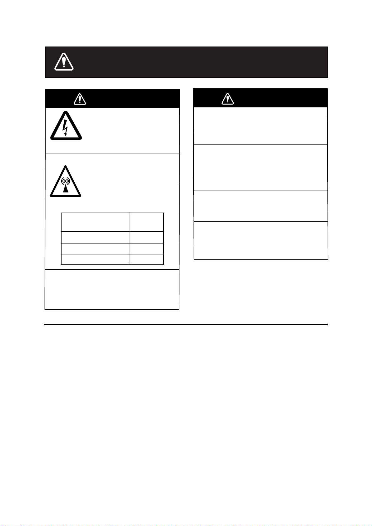
SAFETY INSTRUCTIONS
WARNING
ELECTRICAL SHOCK HAZARD
Do not open the equipment.
Only qualified personnel
should work inside the
equipment.
Do not approach the radome
closer than 1.6 meters when
it is transmitting.
The radome emits radio waves
which can be harmful to the
human body, particularly
the eyes.
RF power density
on antenna aperture
100 W/m
25 W/m
10 W/m
Leave the equipment powered while
underway.
Distress cannot be communicated unless
the equipment is powered.
2
2
2
distance
0.55 m
1.05 m
1.60 m
WARNING
Any repair work must be done by a
licensed radio technician.
Improper repair work can cause electrical
shock or fire.
Turn off the power immediately if water
leaks into the equipment or the equipment is emitting smoke or fire.
Continued use of the equipment can cause
fire or electrical shock.
Do not operate the equipment with
wet hands.
Electrical shock can result.
Do not disassemble or modify the
equipment.
Fire, electrical shock or serious injury can
result.
Important Notice
• No part of this manual may be copied or reproduced without written permission.
• If this manual is lost or worn, contact your dealer about replacement.
• The contents of this manual and equipment specifications are subject to change
without noti c e.
• The example screens (or illustrations ) shown in this manual may not match the
screens you see on your display. The screen you see depends on your system
configuration and equipment settings.
• This manual is intended for use by native speakers of English.
• FURUNO will assume no responsibility for the damage caused by improper use or
modification of the equipment or claims of loss of profit by a third party.
• Please carefull y re ad an d fol low th e operation an d mai nt en ance procedures set
forth in this manual.
• Store this manual in a convenient place for further reference.
i
Page 4

TABLE OF CONTENTS
FOREWORD ......................................................................................................... v
SYSTEM CONFIGURATION................................................................................ vi
SPECIFICATIONS...........................................................................................SP-1
1. INTRODUCTION ...........................................................................................1-1
1.1 General.....................................................................................................................1-1
1.2 Communication services...........................................................................................1-2
2. OPERATION FROM HANDSET....................................................................2-1
2.1 Display Panel and Key Panel of ISDN Handset ......................................................... 2-1
2.2 Switching ON ............................................................................................................ 2-2
2.3 SIM card....................................................................................................................2-3
2.4 ISDN Handset........................................................................................................... 2-4
2.5 FELCOM 50 starts up................................................................................................ 2-4
2.6 Making a call.............................................................................................................2-5
2.7 Redialing...................................................................................................................2-6
2.8 Dialing from phone book............................................................................................2-7
2.9 Incoming calls to handset.......................................................................................... 2-7
2.10 Call hold and transfer................................................................................................ 2-8
2.11 Internal communication............................................................................................. 2-8
2.12 Various call procedures............................................................................................. 2-9
2.13 To call FELCOM 50................................................................................................. 2-10
2.14 Phone book entry.................................................................................................... 2-10
2.15 Phone book editing..................................................................................................2-12
2.16 Analogue telephone................................................................................................ 2-13
3. HANDSET FUNCTIONS................................................................................3-1
3.1 Overview................................................................................................................... 3-1
3.2 Satellite search.......................................................................................................... 3-3
3.3 Phone setup (ISDN Handset).................................................................................... 3-5
3.3.1 Active MSN (Multiple Subscriber Number)...................................................... 3-5
3.3.2 Keyclick.......................................................................................................... 3-5
3.3.3 Ringer............................................................................................................. 3-6
3.3.4 Answer beep................................................................................................... 3-6
3.3.5 Backlight On/Off.............................................................................................. 3-7
3.3.6 Protocol.......................................................................................................... 3-7
3.3.7 Software version............................................................................................. 3-8
3.4 Selecting default Net service provider....................................................................... 3-8
3.5 Setting ports.............................................................................................................. 3-9
3.6 Information available...............................................................................................3-10
4. OPERATION FROM PC ................................................................................4-1
4.1 Installing the PC program.......................................................................................... 4-1
4.2 Starting up.................................................................................................................4-3
4.3 Phone book............................................................................................................... 4-5
ii
Page 5

TABLE OF CONTENTS
4.4 Traffic Log..................................................................................................................4-7
4.5 Traffic log settings......................................................................................................4-9
4.6 Traffic log printout viewer......................................................................................... 4-11
4.6.1 Normal calls (Cct).......................................................................................... 4-11
4.6.2 Mobile Packet Data Service calls (MPDS).....................................................4-12
4.7 Traffic log output to serial printer..............................................................................4-13
4.8 Telefax service.........................................................................................................4-14
4.9 Data service.............................................................................................................4-15
5. CONFIGURATION FROM PC .......................................................................5-1
5.1 Menu functions..........................................................................................................5-1
5.2 Function reference list................................................................................................5-2
5.3 Access level...............................................................................................................5-3
5.3.1 Activating/Changing user PIN code.................................................................5-3
5.3.2 Functions requiring owner level.......................................................................5-4
5.4 Selecting default Net service provider........................................................................5-6
5.5 Phone setup ..............................................................................................................5-8
5.6 Advanced functions ................................................................................................. 5-11
5.7 Access control.........................................................................................................5-12
5.7.1 Restricted dialing...........................................................................................5-12
5.7.2 Restricted dialing setup (owner level onl y).....................................................5-13
5.7.3 Access code (owner level only).....................................................................5-14
5.7.4 Restricted SIM usage....................................................................................5-15
5.8 Software update preparation....................................................................................5-16
5.9 Configuration menu.................................................................................................5-17
5.9.1 ISDN protocol configuration...........................................................................5-17
5.9.2 Net service providers (owner level only)........................................................5-18
5.9.3 Set diagnostics..............................................................................................5-19
5.9.4 Dual-port USB...............................................................................................5-20
5.9.5 Spot beam report method..............................................................................5-23
5.10 Information available................................................................................................5-24
5.11 Customization menu (owner level only)....................................................................5-25
5.12 Routing of incoming calls.........................................................................................5-26
5.13 MSN configuration...................................................................................................5-28
5.13.1 ISDN Handset...............................................................................................5-29
5.13.2 ISDN port......................................................................................................5-31
5.13.3 RS-232 port..................................................................................................5-32
5.13.4 USB port.......................................................................................................5-33
5.14 Saving and reloading configurations........................................................................5-34
5.15 Print handling setup.................................................................................................5-36
5.16 Ethernet interface....................................................................................................5-37
6. DATA COMMUNICATION..............................................................................6-1
6.1 Mobile Packet Data Service (RS-232)........................................................................6-1
6.1.1 Introduction .....................................................................................................6-1
6.1.2 Connecting up.................................................................................................6-2
6.1.3 MPDS-setup....................................................................................................6-3
6.1.4 Checking default settings................................................................................6-9
6.1.5 Connecting to server.....................................................................................6-12
6.1.6 Traffic log ......................................................................................................6-16
iii
Page 6

TABLE OF CONTENTS
v
6.1.7 AT-commands............................................................................................... 6-17
6.1.8 Troubleshooting............................................................................................ 6-19
6.2 Mobile Packet Data Service (USB).......................................................................... 6-22
6.2.1 Introduction................................................................................................... 6-22
6.2.2 Connecting up............................................................................................... 6-23
6.2.3 PC setup....................................................................................................... 6-24
6.2.4 MPDS-setup.................................................................................................6-26
6.2.5 Checking default settings.............................................................................. 6-30
6.2.6 Connecting to server..................................................................................... 6-33
6.2.7 Traffic log...................................................................................................... 6-37
6.2.8 AT-commands............................................................................................... 6-38
6.2.9 Troubleshooting............................................................................................ 6-40
6.3 Mobile Data Service (RS-232) ................................................................................. 6-44
6.3.1 PPP modem via RS-232............................................................................... 6-44
6.3.2 Connecting up............................................................................................... 6-45
6.3.3 PC setup....................................................................................................... 6-46
6.3.4 Checking default settings.............................................................................. 6-52
6.3.5 Connecting to server..................................................................................... 6-55
6.3.6 Troubleshooting............................................................................................ 6-57
6.3.7 AT commands............................................................................................... 6-58
6.3.8 DTE interface................................................................................................ 6-68
6.4 Mobile Data Service (USB)...................................................................................... 6-70
6.4.1 PPP modem via USB.................................................................................... 6-70
6.4.2 PC setup....................................................................................................... 6-72
6.4.3 Checking default settings.............................................................................. 6-78
6.4.4 Connecting to server..................................................................................... 6-81
6.4.5 Troubleshooting............................................................................................ 6-83
7. TROUBLESHOOTING ..................................................................................7-1
7.1 Troubleshooting......................................................................................................... 7-1
7.2 Alarms and messages............................................................................................... 7-4
7.2.1 Introduction....................................................................................................... 7-4
7.2.2 Alarms..............................................................................................................7-6
7.2.3 Clear causes.................................................................................................... 7-9
7.2.4 Troubleshooting: Real time status indications................................................. 7-14
7.2.5 T r o ubleshooting: Other logs ..........................................................................7-16
8. LIST OF TERMS............................................................................................8-1
9. SYSTEM DESCRIPTION...............................................................................9-1
APPENDIX: TERMINAL IDENTITIES.............................................................AP-1
Declaration of Conformity
i
Page 7

v
FOREWORD
A Word to t h e Owner of the FURUNO F E LCOM 50
Congratul ations on your c hoice of the FURUNO FELCOM 50 Inmarsat Fleet F55 Mobile
Earth Stat ion. We are confident you wi ll see why the FURUNO name has become
synony m ous with quality and reliability.
For over 50 y ears FURUNO Elec tric Company has enjoyed an envi able reputation for
quality m arine electronics equipment . This dedication to ex c ellence is furthered by our
extensive global network of agents and dealers.
This equi pm ent is designed and constructed to meet the rigorous demands of the marine
environme nt. However, no m ac hine can perform it s i ntended function unless operated and
maintai ned pr operly. Please carefully read and follow the recommended procedur es for
operati on and m aintenance.
We would appr ec iate heari ng from you, t he end-user, about whether we are achieving our
purposes. Thank you for consideri ng and pur chasing FURUNO equi pment.
Features
The FELCOM 50 mainly c ons ists of an antenna unit, communication unit, and a handset.
The FELCOM 50 provides telephone, facs imile, and data s ervices.
The mai n features of the F E LCO M 50 ar e
• Conforms to the following standards: INMARSAT MINI-M SDM, CN-MM056, 059,
IEC 60945 (Ed. 4), IEC 60529 ( E d. 2), IEC 61162- 1 ( E d. 2)
• Voice communication: 64 kbps & 4.8 kbps
• Facsimile: G4-64 kbps, G3-Max.33.6 kbps
• Always-on Inter net connecti ons vi a MPDS
• Compact antenna unit: φ630x605 mm , 15 k g
Program number
System version of the communi c ation unit: RE L 2.0
Software for PC, vtLite: 6.2
Page 8

SYSTEM CONFIGURATION
Antenna Unit
N Type
Antenna cable
RG-223 25m 5.3
φ
Communication Unit
SF-250
Environmental Category
Antenna unit
Communication unit
ISDN handset, etc
SF-150
N Type
RF
DC IN
(11-32 V)
10 m
12-24 VDC
shipyard supply
ISDN
(RJ-45)
ISDN
(RJ-45)
ISDN
(4 wire)
RS-232C
RS-232C
USB
2 pin
standard supply
ISDN Handset
SF-870
RJ-45
ISDN cable
RJ-45
Dsub9
Dsub9
USB (B)
QRPM911-3000
(3 m)
ISDN bus: max 100 m
103776
9-pin to 25 pin printer cable
RS-232C cable
R906686
(3 m)
USB cable
100001(3 m)
DC OUT
AC-DC Power Supply
PR-240
DC IN AC IN
DPYC-2.5
Dsub25
RS-232C
DPYC-1.5
24 VDC 100-115/200-230 VAC
To be installed in an exposed area
To be installed in a protected area
RJ-45
Dsub9
USB (A)
Terminal
Adapter
QDGY 911912
Printer
PC
RJ-11
ISDN
Wall Socket
102176
RJ-45
ISDN Handset
optional supply
RJ-11
G3 FAX
FAX-2820
SF-870
ISDN
Wall Socket
102176
RJ-45
RJ-45
QDGY 911912
RJ-11 RJ-11
Terminal
Adapter
RJ-45
RJ-45
ISDN
Wall Socket
102176
FAX-2820
G3 FAX
Telephone
DBAR104001/888
Telephone
FC755D1
(Japanese)
vi
Page 9

FURUNO
SPECIFICATIONS OF THE INMARSAT FLEET F55 SHIP EARTH STATION
FELCOM 50
1. ANTENNA UNIT
Gain Greater than 17.5 dBi
Axial Ratio Less than 2.0 dB
Polarization Right circularly polarized wave
Antenna Beamwidth 20 deg. approx. (at –3 dB)
Stabilization Triple-a xis control type
Tracking Step tracking system
2. COMMUNICATION UNIT
Standard Functions Global beam: Voice 4.8 kbps
Spot beam: Voice 64 kbps
G3 FAX 9.6 kbps, G4 FAX 64 kbps
FELCOM 50
Data 56 kbps, 64 kbps
(UDI, 3.1 k audio, speech)
MPDS 64 kbps
Transmit Frequency 1626.5 MHz to 1660.5 MHz
Receiver Frequency 1525.0 MHz to 1559.0 MHz
G/T Better than -7 dB/K
EIRP BPSK: 20 +1/-2 dBW
0-QPSK (4.8 k Voice): 20 +1/-2 dBW
0-QPSK (9.6 k FAX): 22 +1/-2 dBW
16QAM : 25 +1/- 2 dBW
3. INTERFACE
PC: RS-232/RS-422
Navigator: IEC 61162-1 ed.2 (2000/7)/NMEA0183
USB: B connector
ISDN: Max 3 ports (2-RJ-45 connectors and 1-terminal)
4. POWER SUPPLY
Power supply 12-24 VDC
Rated current 1.3 A (St-by), 3.5A (Tx) at 24 VDC
SP-1
Page 10

FURUNO
SP-2
5. ENVIRONMENTAL CONDITION
Category of unit Antenna unit: To be installed in a Exposed area
Others: To be installed in a protected area
Ambient Temperature Complies with Inmarsat SDM and IEC 60945 (Ed.4)
Antenna unit: -25°C to +50°C
Communication unit: -15°C to +55°C
Handset: -15°C to +55°C
Relative Humidity 95% at 40°C (Inmarsat SDM 95 & IEC 60945)
Waterproofing Complies with IEC 60529;
Antenna Unit: IPX6
Communication Unit: IPX0
Handset: IPX0
Vibration Complies with IEC 60945
● 2 - 5 Hz and up to 13.2 Hz with an excursion of ±1 mm ±10 %
(7 m/s
2
maximum acceleration at 13.2 Hz)
FELCOM 50
● 13.2 - 100 Hz with a constant maximum acceleration of
7 m/s
Complies with Inmarsat SDM
2
ADU: Frequency 4-10 Hz: Max. vibration 2.54 mm
Frequency 10-15 Hz: Max. vibration 0.76 mm
Frequency 15-25 Hz: Max. vibration 0.40 mm
Frequency 25-33 Hz: Max. vibration 0.23 mm
BDU: Frequency 4-15 Hz: Max. vibration 0.76 mm
Frequency 15-25 Hz: Max. vibration 0.40 mm
Frequency 25-33 Hz: Max. vibration 0.23 mm
Frequency 33-40 Hz: Max. vibration 0.13 mm
Frequency 40-50 Hz: Max. vibration 0.07 mm
Motion Roll: ± 30°/8s, Pitch: ± 10°/6s, Yaw: ± 8°/50s, Surge: ± 0.2G,
Sway: ± 0.2G, Heave: ± 0.5G, Rotation: 6°/s, Speed: 30 kt
6. COATING COLOR
Antenna Unit Munsell N9.5
Communication Unit Munsell N1.0
ISDN Handset Munsell N1.0
Page 11

1. INTRODUCTION
1.1 General
The FELCOM 50 consists of the Above Deck Eq uipment (ADE) and Below Dec k
Equipment (B DE ) .
Above Deck Equipment - ADE
The FELCOM 50 A bove Dec k E quipment consists of:
• Servo stabilized antenna dish with RF-Transceiver
• GPS receiver
• Radome
• Optional tower or mast m ounting
Below Deck Equipment - BDE
The FELCOM 50 Communication Unit (CU) - which constitutes the major
electronic part - is designed for wall or desktop installation.
The CU mai ns input is 12-24 VDC ( ac tual power 11-32 VDC).
The CU suppl ies 48 VDC power to the ADE through the coaxial cable.
ISDN Handset
The I S DN Handset keypad and built-in display allow dialing and cont r ol of the
CU and antenna.
CD
The CD ROM s upplied with FELCOM 50 cont ains program for PC (vtLite Mobile)
and driver software.
1-1
Page 12
1. INTRODUCTION
1.2 Communication services
FELCOM 50 pr ov ides the following services:
• Speech: 64/4.8 kbps
• Data: 56/64 kbps (UDI)
• MPDS: Mobile Packet Data Service
FWD = 64 kbps, RTN = 64 kbps
Shared chan nel
• Telefax: 9.6 kbps G r oup 3 via Terminal A dapter (TA)
64 kbps Group 4
• Audio 3.1 kHz (Audio)
Internal co mmunication
Equipment connected to the various interfaces may c omm unicate with eac h
other via an internal M S N (Multiple Subs c r iber Number) assigned to each unit.
However, calling fr om an analog telephone vi a terminal adapt er is not possible.
Control interface
The RS-232/RS-422 or USB port allows connection of a PC for c onfiguration of
the FELCOM 50 Communication Unit (CU).
A PC program (vtLite Mobile) that provides the software to operate and co nfigure
the CU is supplied on the enclos ed CD (requir es at least Windows 98).
.
/
0
'
.
!
#
!
'
'
-
!
"
#
$
%
&
'
(
)
*
+
,
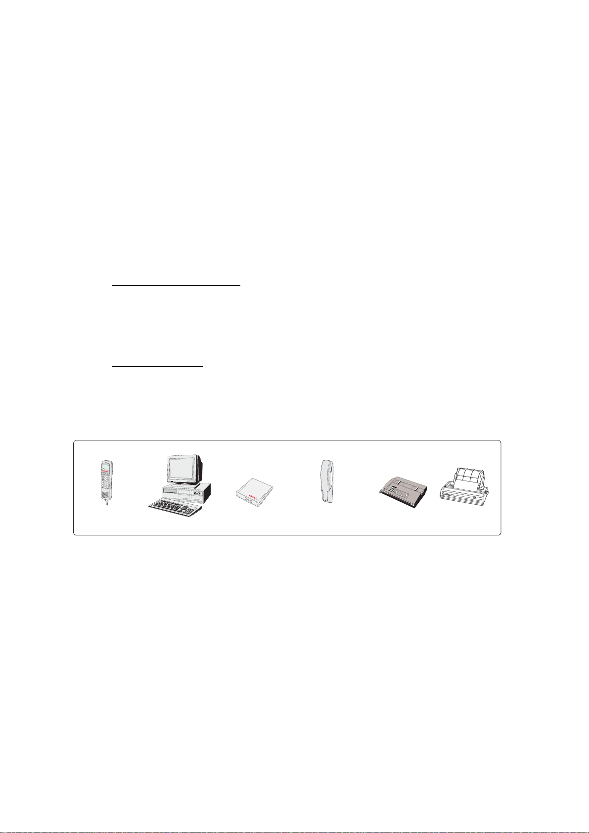
Additional
ISDN Handsets
PC
Terminal Adapter
Analogue telephones
(wall or desk)
Telefax
(Group 3 or 4)
Serial printer
Additi onal equipment
1-2
Page 13
2. OPERATION FROM HANDSET
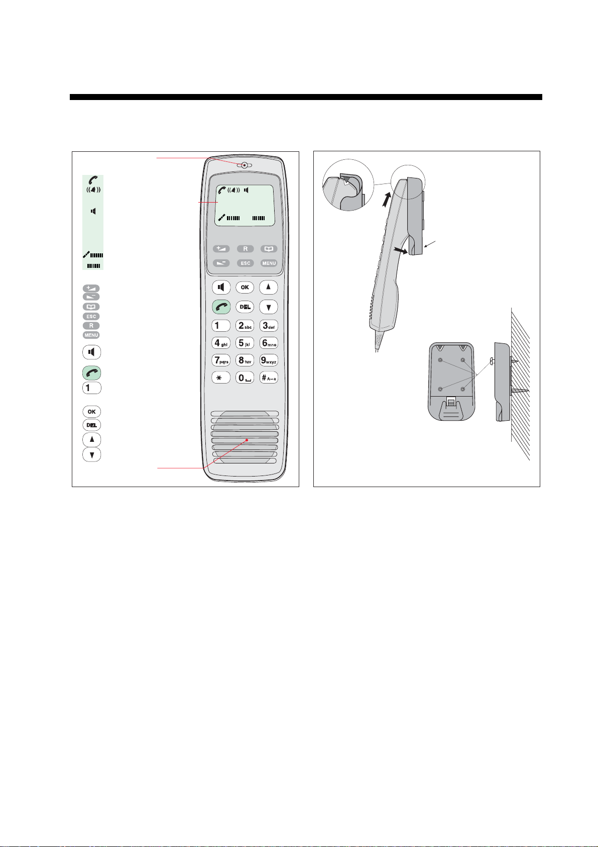
2.1 Display Panel and Key Panel of ISDN Handset
Handsfree microphone
Display indicators:
appears at hook OFF
flashes when receiving a call
Net provider & Ocean Region
appears when loudspeaker
is ON
appears when selecting
ALPHA
letters on the keypad, e.g. for
Phone Book entries
signal strength indicator
alarm indicator
Function keys:
allows adjusting the earpiece
volume during conversation
opens/closes Phone Book
reverts to previous position
used to transfer a call
selects function menu
handsfree microphone/
loudspeaker ON/OFF (hook
ON/OFF when in cradle)
hook ON/OFF
. . . . . number keys.
The keys include letters for
Phone Book entries.
enters selected choise
deletes last character or
complete entery
scrolls up/down through
function menu/choices
Handsfree loudspeaker
Display and keys
ISDN
ALPHA
KDD IOR
Ready for call
Hook ON magnet
click!
Holder/cradle wallmounted
2-1
Page 14
2. OPERATION FROM HANDSET
2.2 Switching ON
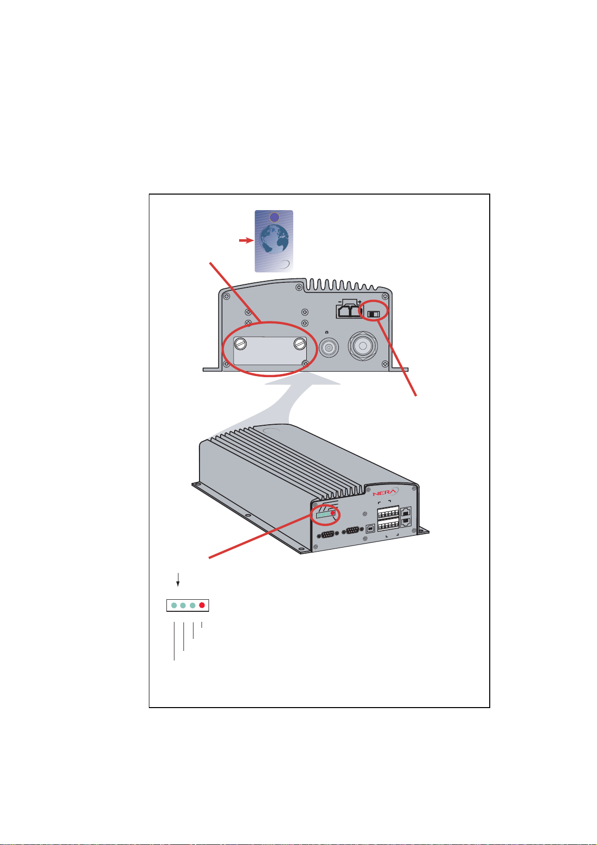
The ON/OFF switch loc ated on the rear panel of the Communication Uni t
swit c hes all basic units of the FELCOM 50 terminal on/off:
• the ISDN Handset
• the Communication Unit (CU), and
• the Antenna Unit .
See figure below for location of the power ON/OFF swi tch and indicat or.
SIM card
Cover
WHEN CHANGING MODEM UNIT
Communication Unit
SIM CARD INSIDE
REMOVE COVER
AND TAKE OUT SIM CARD
Insert SIM card, contact upside down.
ON/OFF
11-32 VDC / 110W
NOT IN USE RFSIM CARD
(50 TERM)
Power
ON/OFF
switch
F33
F33
Nera
Nera
RS-232
4
5
9
ON
48V DC
SYNC
ALARM
RS-232 B
4
5
A
1
2
3
9
6
7
8
ISDN
RX-
RX+
ISDN
TX-
TX+
8
1
1
USB
1
2
3
6
7
8
8
ISDN
RX+
RX-
TX+
TX-
RS-422
NMEA+
NMEA-
2-2
Power
indicator
LED's
(G: Green, R: Red)
G G G R
Alarm: indicates that an alarm occurs.
SYNC: indicates that the unit is synchronized with a satellite.
48 VDC: indicates that 48 VDC is supplied to the antenna.
ON: indicates that the power is turned on.
Location of SIM card and ON/OFF switch
Note: W ait about 10 sec onds to turn on the power after turning it off.
Page 15

2.3 SIM card
The SIM c ar d car r ies subscription inform ation from your Net service provider on
an integrated c ircuit. The FELCOM 50 used with the SIM card assumes the
identity of the SIM card.
The SIM c ar d has its own set of Inmarsat Mobile Numbers (IMN) on which the
user can be contacted irrespecti ve of the FELCOM 50 used. All outgoing calls
will be bi lled to the owner of the SIM card.
The SIM c ar d is protected by a SIM PIN (Personal Identif ication Number).
Contact your Net service provider if you do not have the PIN code.
If the PI N c ode ent er ed does not match the PI N code o n the SIM card, operation
with that particular SIM card will lock-up after three failed attempts. You must
then use the SIM un-bloc k c ode (P UK c ode) provided by your Net ser vi ce
provider to un- lock the card. Contact your Net service provider if you do not
have the PUK co de.
Note: When the PUK is us ed, the SIM PIN is set to 1 2 3 4.
To change or disabl e the PIN code, s ee " 5. 3 Access level" later in this m anual.
The SIM c ar d can s tore various infor m ation, e.g.:
2. OPERATION FROM HANDSET
• PIN code (Personal Identification Number)
• Phone book
• Allowed Net service pr oviders
Note: FELCO M 50 can be used with or without S IM card. The Net service
The SIM c ar d driver is located on the rear panel of t he Com m unication Uni t, see
page 2-2. The cover must be r emoved to access the card s lot. T he c over is
attached by two serrated screws. No t ools are required to loosen the screws.
Note: Turn on the power, wait for the indi cation “Ready for call”, and t hen insert
When entering S IM card, the terminal pr om pts you for SIM PIN:
provider, however, someti m es r equires the use of SIM card.
the SIM c ar d. If the ship’s mains is turned off instantaneously, eject the
SIM car d and turn the power off and on again.
Fleet F55
SIM PIN:
2-3
Page 16
2. OPERATION FROM HANDSET
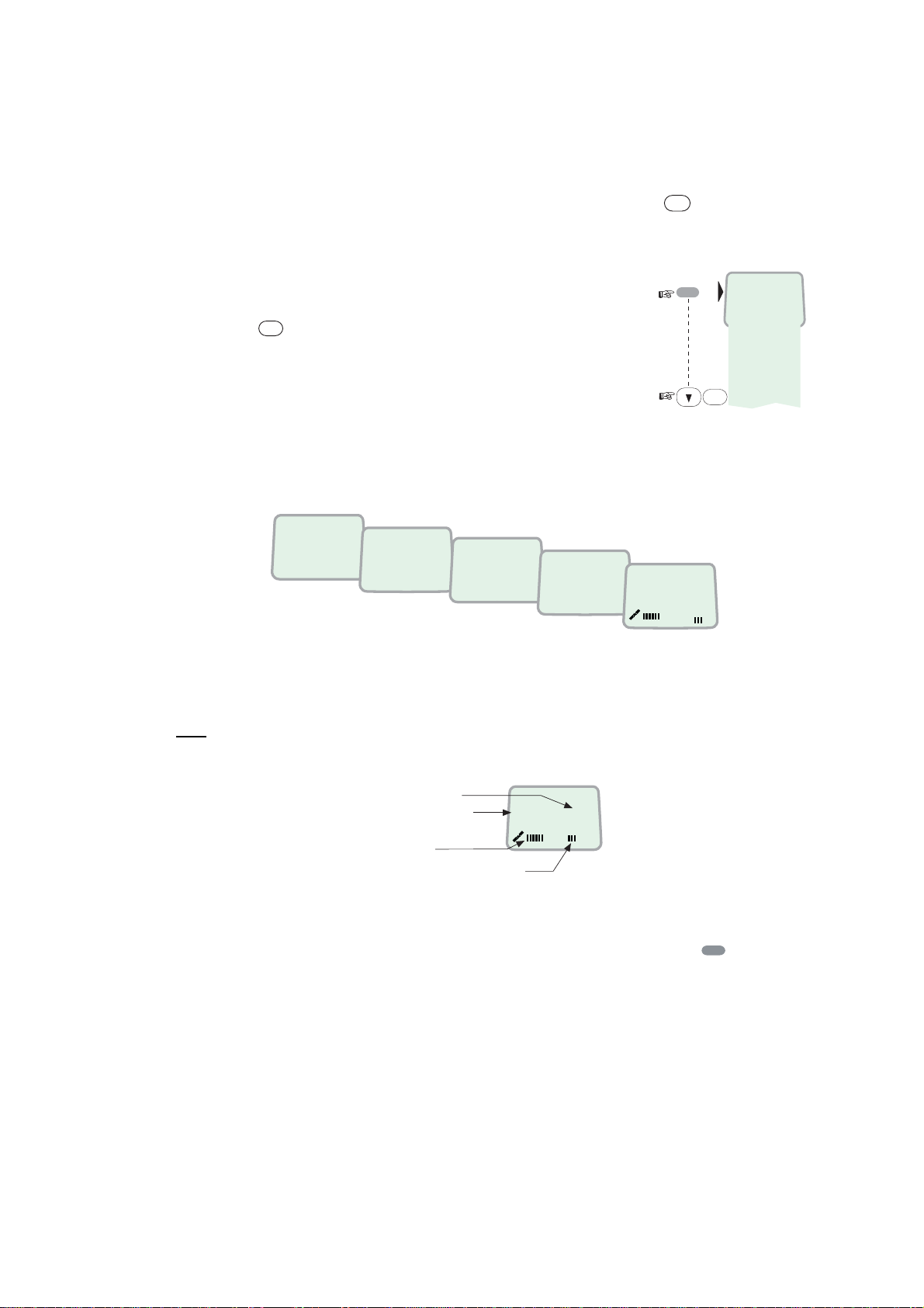
2.4 ISDN Handset
When connect ed initially, the handset is automatically set to Fleet mode,
providing an idle display as shown on nex t section.
To switch back to ISDN Handset mod e, press and hold down
ON power.
Swit c hing back to Fleet mode is then achieved as follows:
1. Open the MENU and scrol l down
to Reset to Fleet
OK
2. Press
.
The handset will now
stay in Fleet mode.
2.5 FELCOM 50 start s up
FELCOM 50 automatically initializes the system and searches for the satellite.
DEL
when turning
MENU
>Active MSN
Kayclick
Ringer
Answer beep
Backlight
Language
MSN
Protocol
SW version
Reset to Fleet
OK
Furuno Fleet
Euro-ISDN
Waiting
KDD
Initializing
IOR
KDD
Searching
IOR
KDD
Ready for call
IOR
See “3.2 Satellite search” in this manual to restart a s ear c h manually.
If required, see "3.4 Selecting default Net service provider".
Idle
When idle, the ISDN Handset displays as follows.
Ocean Region
Service provider
Signal strength
indicator
Alarm indicator
KDD IOR
Ready for call
The alar m indicator flas hes when an alarm cond ition occurs. The indic ator stops
MENU
once the alarm has been read in the Displ ay Hands et by pressi ng
>
Inform ation > A larms & messages” .
The indicator continues to be displ ay ed if the alarm condition persists.
Note: I f t he s ear ching begins suddenly due to satellite blocking, restart a search
manually, specifying your ocean region. See page 3-3 for details.
2-4
Page 17
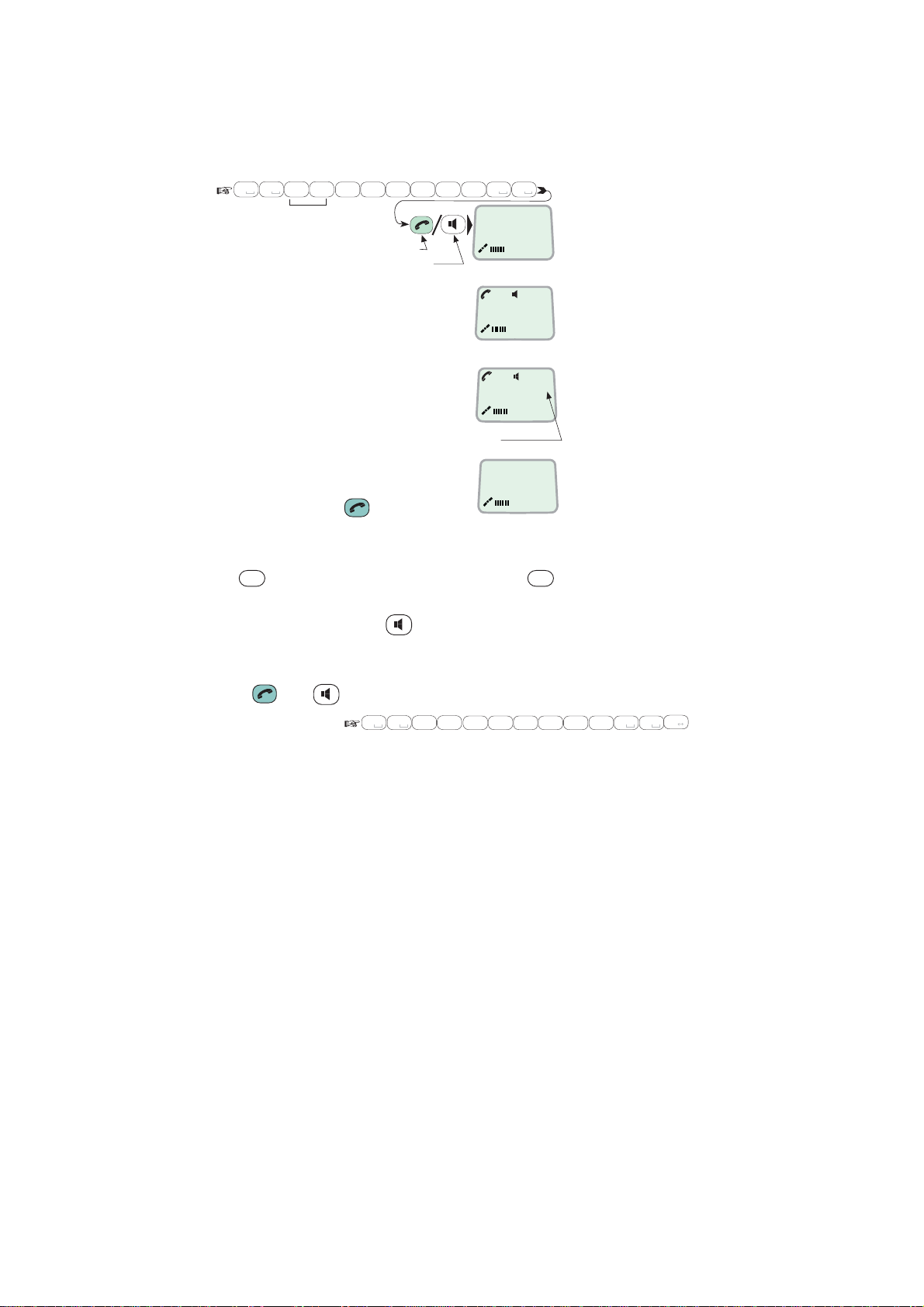
2.6 Making a call
1. Dial 00, c ount r y code and subscriber number, e.g.:
0 8
0
abc
Japan
1
6
pqrs
2
abc
7
mno
pqrs
For normal call
For handsfree call
2. OPERATION FROM HANDSET
abc
7
0 0
pqrs
Dial (4.8K)
008167244700
4
4
abc
• When entered, the display
reads:
Calling ...
008167244700
• When the remote end a ns wers,
the displ ay reads:
Connected 09:46
008167244700-
The timer starts.
Timer, minutes:seconds
2. End the call by pr es s ing
hook ON/OF F
, or
Disconnected
replacing the handset in the cradle.
Use
DEL
key to modify entries: Pres sing
DEL
key once, erases one digit.
Holding the k ey more than 0.5 second erases the whol e num ber.
Use the handsf r ee key
to toggle the l ouds peaker ON/OFF.
Alternati v e dialing:
Press
or to get the dial ing tone, then di al the number.
#
0 8
0
abc
1
6
pqrs
2
7
mno
pqrs
4
4
abc
abc
0 0
abc
7
pqrs
A a
2-5
Page 18
2. OPERATION FROM HANDSET
2.7 Redialing
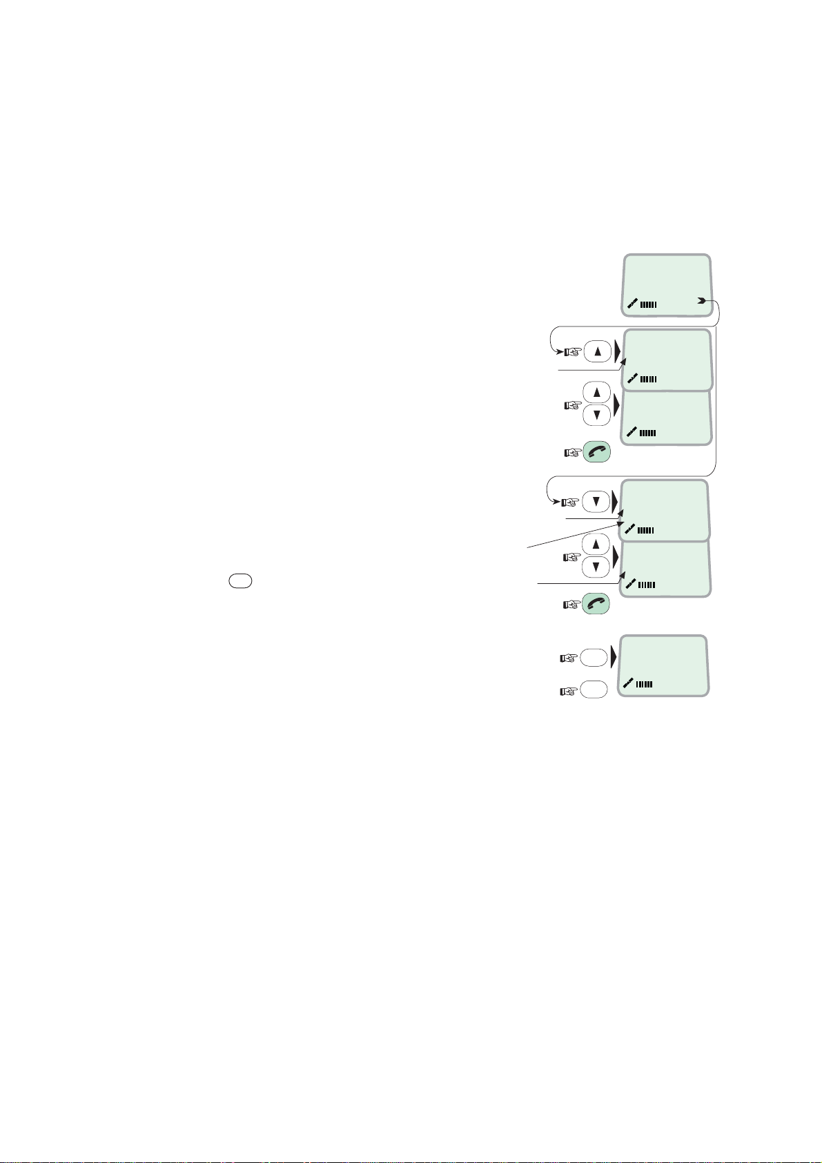
The Redial Memory stores t he last 30 called and received numbers (incoming
IMN numbers are not convey ed from “ashore”).
The data are erased when disconnecting the handset or FELCOM 50 is switched
off.
To redial calls made:
1 Press the arrow up key to recall the
latest num ber dialed.
2 Use the arrow keys to scroll through
the lis t.
3 Pressing hook ON/OFF sends the
chosen numb er.
To view calls received:
4 Press the arrow down k ey to recal l the
last number rec eived. Scroll through
list.
To delete a listed num ber :
DEL
5 Press
from list.
Press OK t o delete:
Revert to idle:
to clear the chosen number
"Redial list entry"
appears if no number
is stored
"Received call list"
if no number is stored
Initiall call
External call
KDD IOR
Ready for call
OUT: Aug 01 02:11
008179803113 01
OUT: Aug 01 01:45
008179560215 02
IN:JAN20 13:09
20 01
INFEB10 16:11
unknown no. 02
DEL
Clear?
00467244700
OK
››
››
2-6
Page 19
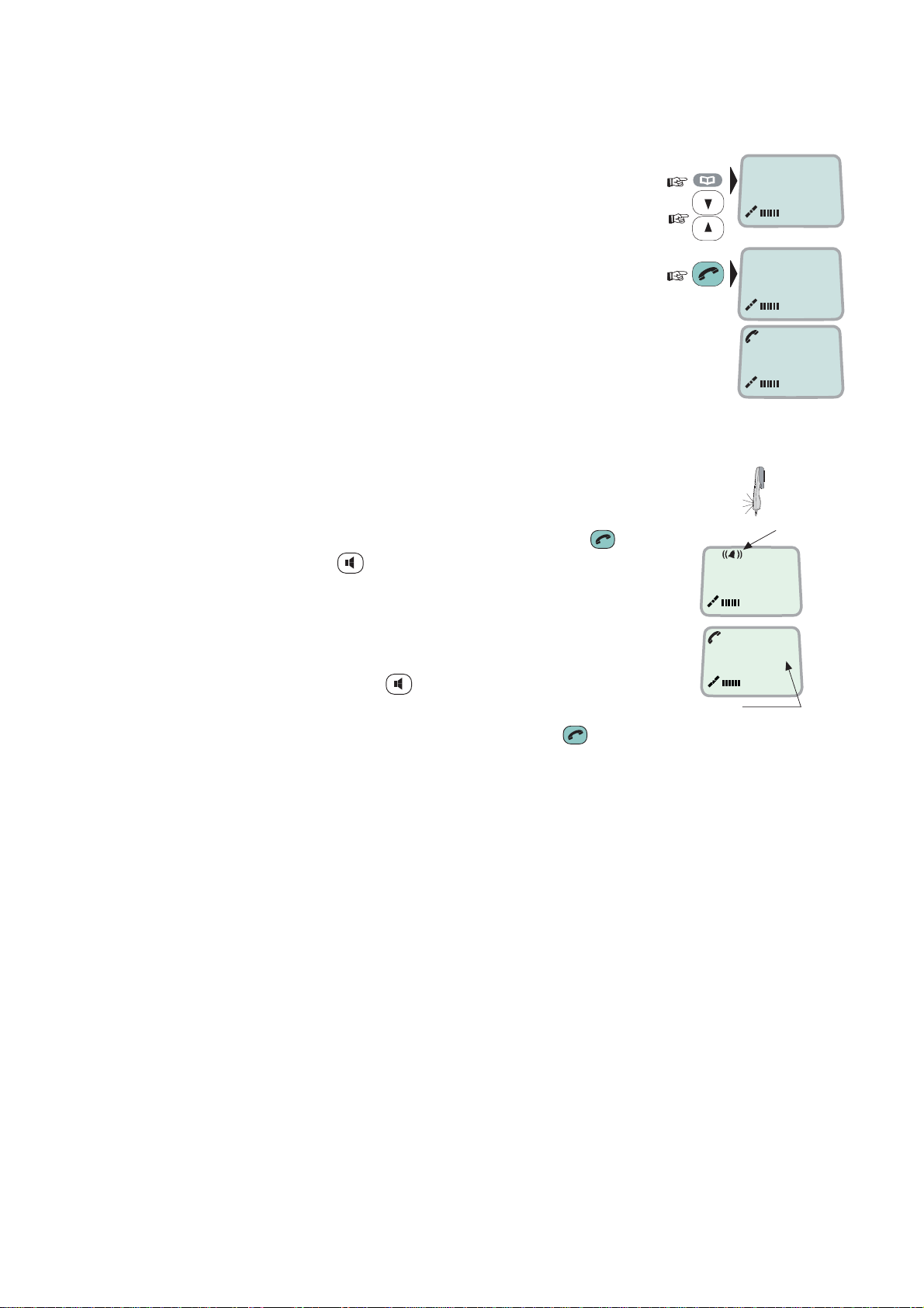
2.8 Dialing from phone book
2. OPERATION FROM HANDSET
1 Press the phone book key and s c r oll through
the phone book .
2 Press the hook ON/OFF k ey to call the
selected number.
2.9 Incoming calls to handset
The handset r ings when rec eiving a call. The ringing s ymbol
flashes unt il the call is answered.
• Answer the call by pr es s ing hook ON/OF F key or
handsfree key
With the IS DN Handset in the c r adle, the loudspeaker and
microphon e ar e O N for handsfree operati on.
If lif ting the handset, the loudspeaker turns off.
Use the handsf r ee key
• End the call by pressi ng hook ON/OFF key , or
replacing the handset in the cradle.
to toggle the l ouds peaker on/off.
›› BT
Furuno
BT
Calling ...
Ringing symbol
4.8 Speech
00:00
Timer,
minutes:seconds
ALPHA
ALPHA
• Reject the call by pr es s ing DEL key.
Note: If the ri nging symbol is displayed when in idle, you have missed a call.
2-7
Page 20
2. OPERATION FROM HANDSET
2.10 Call hold and transfer
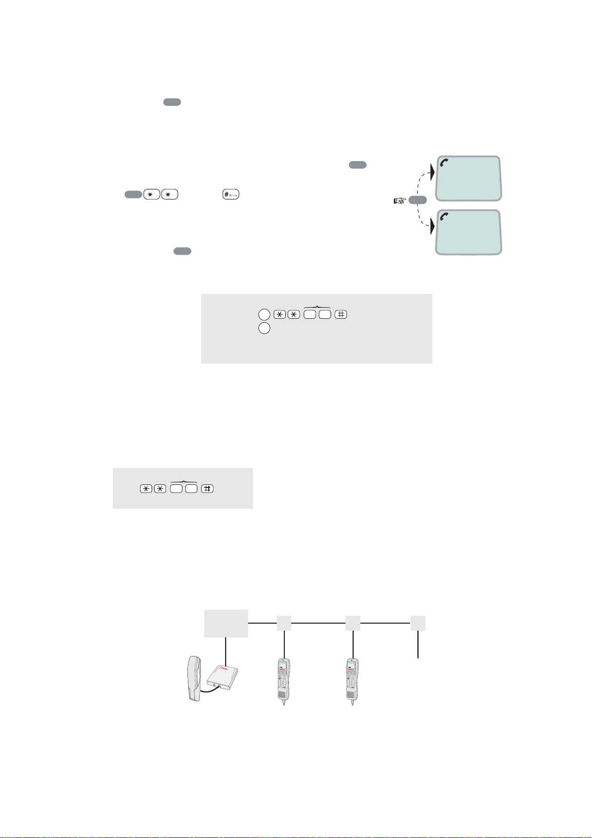
Pressing
R
during a conversat ion will put the current cal l on hold. Another
internal c all may now be made.
Swit c hing bet ween the two calls:
• After putting the 1
nd
the 2
• The 1
call is established by key ing:
R
[MSN]
st
call is put on hol d, and the 2nd is connected.
st
call on hold by pr ess ing
• Toggling between the two calls is achi eved by
R
pressing
repeatedly.
Call tr ans f er ( c onnec tion via sat ellite):
MSN/Handset ld
2
R
toggles between subscribers
R
0
Hang up
Exception!
Transfer from analogue to ISDN is not possible.
R
,
1 on hold
**20#
R
2 on hold
2.11 Internal communication
FELCOM 50 allows calls t o be m ade internally between the connec ted ISDN and
analogue telephones.
Internal calls:
MSN (example)
2
0
When receiving a call t o an ISDN phone, the caller’s MSN number will appear in
the displ ay (if programmed). When FELCOM 50 is busy with a s atellite link c all, it
is possible to make internal calls.
Example of internal call connections:
CU
)
$
.
5
+
"
,
.
#
$
!
/
0
1
%
&
2
3
'
()
*
4
TA
Analogue
phone
MSN21
ISDN Handset
MSN20
MSN22
ISDN Handset
)
$
.
5
+
"
,
.
#
$
!
/
0
1
%
&
2
3
'
(
)
*
4
MSN23
MSN24
ISDN DECT
phone
MSN25
2-8
Page 21

2.12 Various call procedures
Call from a standard telephone
2. OPERATION FROM HANDSET
0 0
8
1 6 7 2 4 4 7 0 0
Short number dialing from Phone Book (prefix 23)
2 3 1 5
fetches and sends the telephone number stored in the Phone
Book under short number 15.
Short number dialing (prefix 23) through selected Net service provider
3
2 3 1 5
fetches and sends the telephone number stored under
short number 15 via the selected Net service provider (KDDI=no.3).
Service calls
Special infor m ation services are accessible wit h 2-digit service address code.
Note: Not all Net s er vi c e providers offer every service.
Examples:
Obtaining assistance from the International Operator:
1 1
Calling the technical staff of the Land Earth Station (LES):
3 3
Telefax
On a telef ax with keypad, enter
as the last di git before star ting
transmission.
0 0
8
1 6 7 2 4 4 6 2 1
START
Note: Some types of equipment do not ha ve # i mplemented in softwar e ev en if
the #-key is on the keypad. Then in front of the telephone number us e.
903 if dialing the number digit by digit, or
902 if for the number to be sent as a block. e.g.:
9 0 2 0 0 4 7 6 7 2 4 4 7 0 0
2-9
Page 22
2. OPERATION FROM HANDSET
2.13 To call FELCOM 50
Dial the international prefix (nor m ally 00) followed by 870 and the IMN number,
e.g. 00 870 762420510.
The common Ocean Region access no. 870 connects the c all to the dialed
FELCOM 50 terminal regard les s of the Ocean Region the terminal user currently
comm unicates through.
If the Net s er vice provider does not support ac cess no. 870, call the Ocean
Region directly:
871 – AOR-E (Atlant ic Ocean Region Eas t)
872 – POR (Pacific Ocean Region)
873 – IOR ( Indian Ocean Region)
874 – AOR-W (Atlantic Ocean Region West)
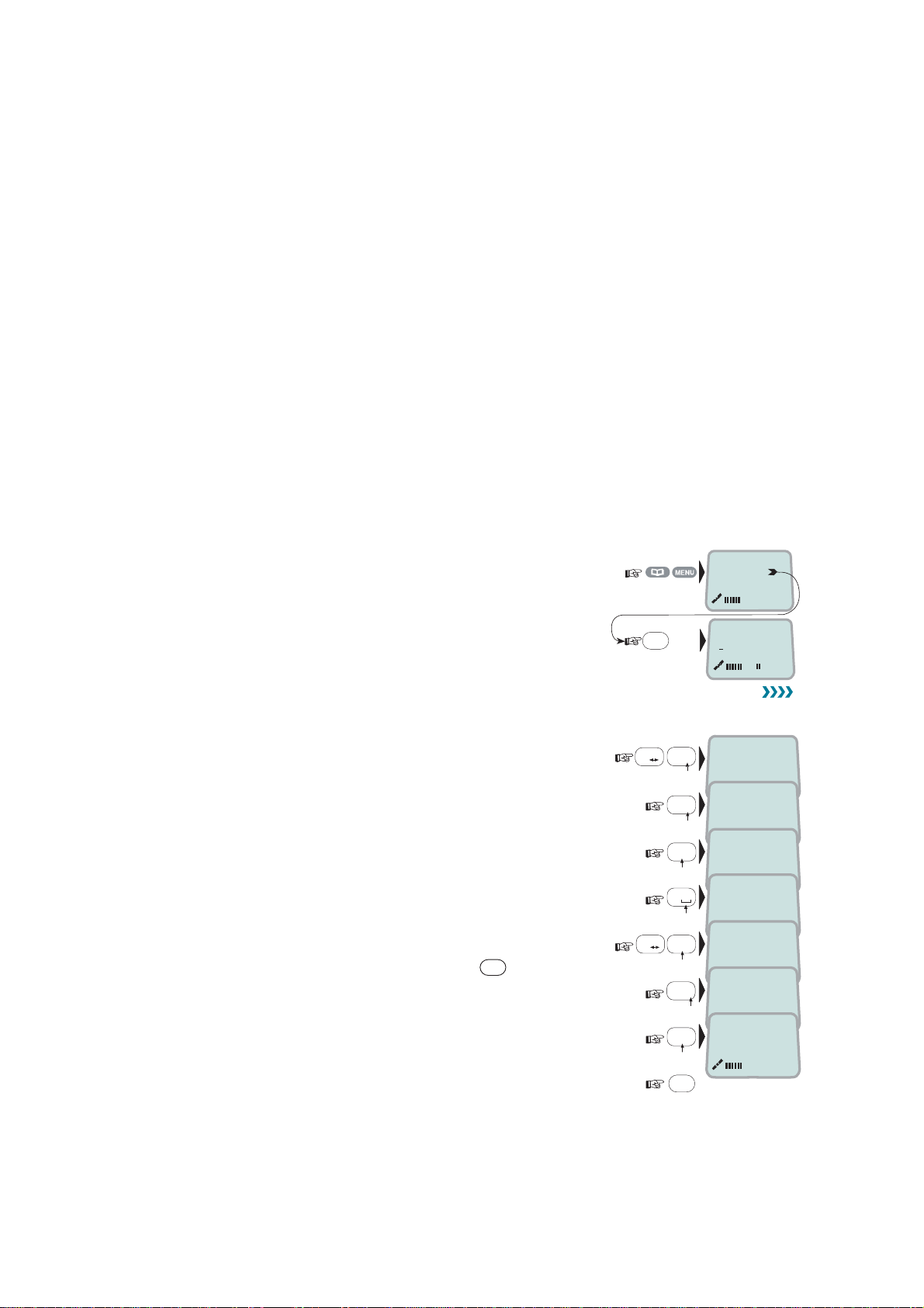
2.14 Phone book entry
The entries in the FELCOM 50 phone book may consist of m ax imum 100
numbers. The number/ nam e list i s st or ed in the Communication Unit.
Programming:
1 Open the phone book > menu.
2 Open the Add entry function by press ing Ok
before st ar ting to key in c har acters:
››
Add entry
Edit number
OK
Add name:
ALPHA
3 Enter the name, e.g. Fera ASA:
Press [3] k ey t h ree time to enter “F” and as follows:
Note that the additional characters accessible
with the key appear momentarily.
See the character table on next page.
For modifying an entry,
see “2.15 P hone book editing.”
DEL
An entry can be er ased by pressing
4 Press the OK key.
#
A
a
#
7
2
0
2
7
2
pqrs
abc
abc
pqrs
abc
OK
Fe_
Add name:
Fer_
Add name:
Fera_
Add name:
Fera _
Add name:
Fera_A
Add name:
Fera_AS
Add name:
Fera_ASA
Add name:
3
def
A
a
ALPHA
ALPHA
ALPHA
ALPHA
ALPHA
2-10
Page 23
2. OPERATION FROM HANDSET
1
8
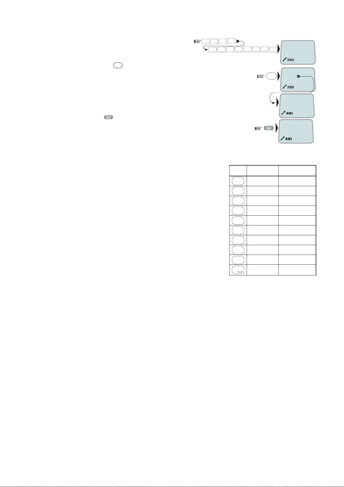
5 Enter the t elephone number e.g.:
0
tuv
0
4
2
6
mno
abc
7
pqrs
6 Pressing
OK
stores the entry in
the phone book .
7 Press
to revert to idle.
The character table shows all the characters ac c es sible.
Notes:
• The # -key toggles between upper-case
and low er - c ase c har ac ters.
• Names written with none A nglo-American
characters such as Æ, Ø, Å et c ., c an only
contai n 6 different special char ac ters
Key Uppercase Lowercase
1
2
3
4
5
6
(however, 2 equal character s c ount as 1).
7
8
9
wxyz
0
0
7
abc4abc
pqrs
0
OK
››
Fera ASA
Neratek
KDD IOR
Ready for call
. , ? ! - : ; / 1 . , ? ! - : ; / 1
ABCÆÅÄ2 abcæåä2
abc
DEF3 def3
def
GHI4
abc
JKL5 jkl5
jkl
MNOØÖ6 mnoøö6
mno
PQRS7 pqrs7
pqrs
tuv
TUVÜ8 tuvü8
WXYZ9 wxyz9
_0 _0
ALPHA
Number...
008167244700
Saving
20
ghi4
2-1 1
Page 24
2. OPERATION FROM HANDSET
2.15 Phone book editing
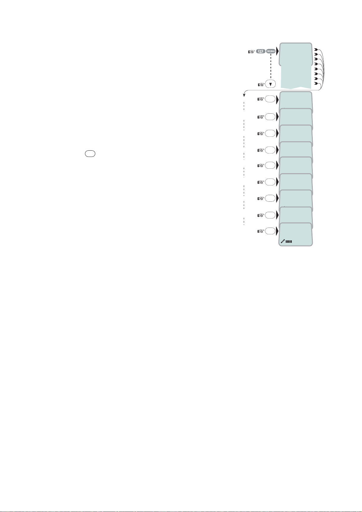
Open phone book m enu and scrol l down to the
required function.
If "Sort by S hr tNo" is selected, the functi on
swit c hes to "Sort by Name".
ALPHA appear s when letters are
to be entered.
DEL
Use
to modify entr ies.
Add Entry
Edit
number
Edit name
Delete
Search
book
See
number
Copy
Short by
ShrtNo
Sort by
name
››
OK
Add name:
Furuno Satcom_
OK
Number:
004767244700
OK
Edit name:
Furuno Satcom
OK
Deleting
OK
Name search:
_
OK
[1] 0047672447
00
OK
Short Number:
2_
OK
[1] 0047672447
00
OK
Furuno
Add Entry
Edit number
Edit name
Delete
Search book
See number
Copy
Sort by ShrtNo
ALPHA
ALPHA
ALPHA
ALPHA
ALPHA
ALPHA
ALPHA
2-12
Page 25
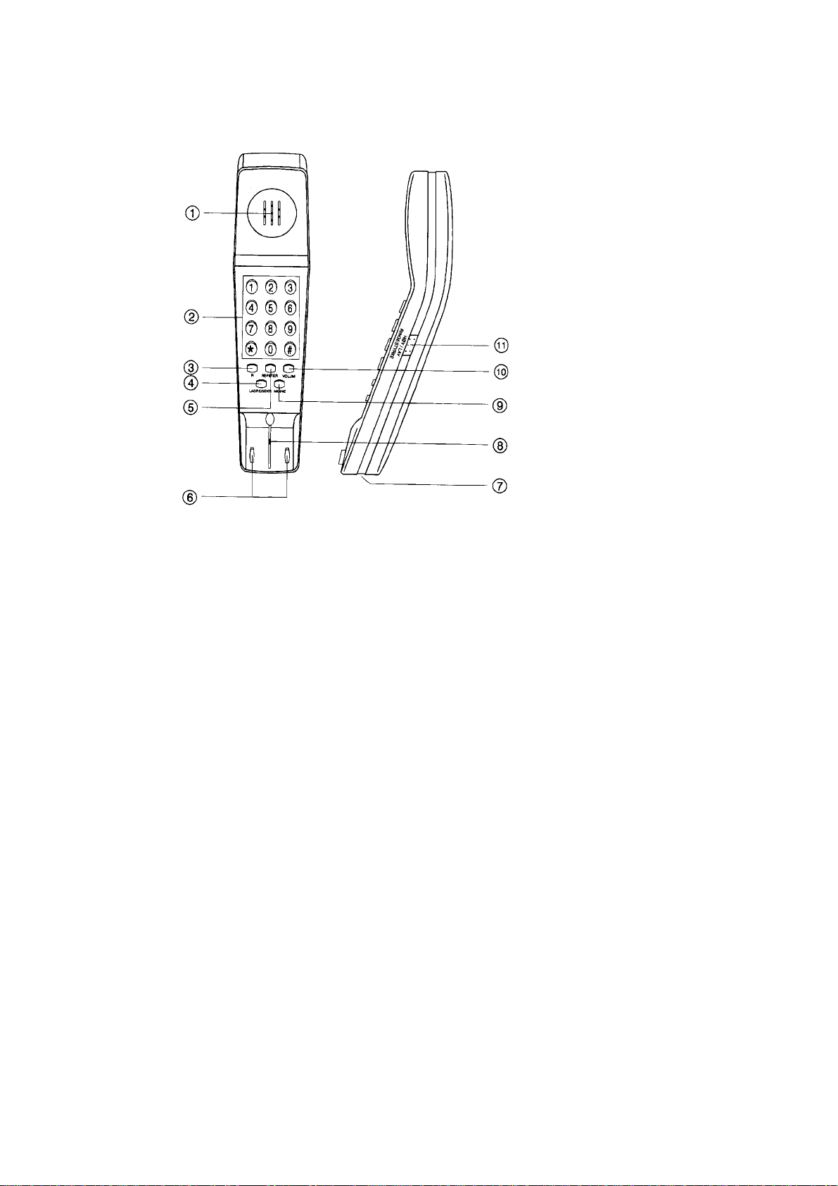
2.16 Analogue telephone
muting
2. OPERATION FROM HANDSET
1 Speaker
2 Keypads
3 R-button (not used)
4 Storing / Mi c r ophone
5 Last number r edial
6 Hook on / off
7 Line cable outlet
8 Microphone
9 Memory (stored numbers)
10 Volume control
11 Ringing signal High / Low
Outgoi ng call
1 Lif t handset and receive dial tone
2 Dial t he s ubs c r iber number (and #)
3 When finished, replace the handset
Redialing
If the subsc r iber is busy, or you want to mak e a new call to the last dialled
subscriber, you can lift the handset , receive new dial t one and t hen pr es s the
[REPETER] button.
Note that this button is for manually dialled num ber s only. Stored num ber s will
not be repeated us ing this m ethod.
Storing ab br e vi a te d numbers
Ten subscriber num bers can be st or ed in the telephone’s memor y in short from.
The numbers c an be used for out going call, by pushi ng 2 buttons only.
1 Lift handset and press [LAGRE/SEKR] b ut ton (Don’t worry the dial tone)
2 Press [MINNE] button.
3 Select r elevant storing address by pushing one butt on.(0 - 9)
4 Dial t he s ubs c r iber no. and # (max. 21 digits).
5 Press [LAGRE/SEKR] button.
6 Replace handset. The number is st or ed.
7 Repeat the s tep 1 - 6 to store addi tional numbers.
If requir ed to change a number, just overwrite exist ing number.
2-13
Page 26

2. OPERATION FROM HANDSET
Abbrevi at ed call
1 Lif t handset and receive dial tone
2 Press [MINNE] button.
3 Press rel evant storing address (0 – 9). The subscriber number is
automatic ally dialled.
Note: If you put the analogue phone, facing the key pad dow n for holding on
call, the line will cut.
2-14
Page 27
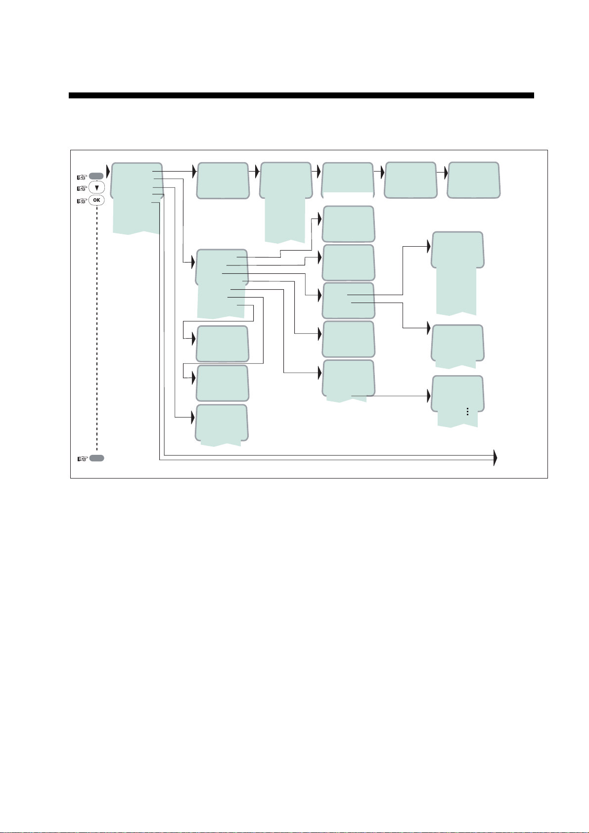
3. HANDSET FUNCTIONS
3.1 Overview
MENU
ESC
››Sat. Search
Phone setup
Set Network
Ports
Information
Opening Search
››Active MSN
Keyclick
Ringer
Answer beep
Backlight
Protocol
SW version
1.4.00 270103
›› Euro-ISDN
Nl-1*
›› 002/Stratos
004/Telenor
005/OTE
012/XANTIC
››
Search
AOR-W
AOR-E
POR
IOR
Region 4
Region 5
Region 6
Not in use
Region 7
all
Searching...IOR
Elevation 0
Elevation: 0...90
›› #1: 4.8 Speech
#2: 64k Speech
›› On
Off
›› Tone
Volume
›› On
Off
›› On
Off
30 second
Dimmer
o
Tuning to IOR
Elevation 17
KDDI IOR
Ready for call
›› Tone#1
Tone#2
Tone#3
Tone#4
Tone#5
Tone#6
Tone#7
Tone#8
Tone#9
›› Low
Medium
High
Increasing
Dimmer [100%]
90%
10%
See next pagereverts to idle
*: NI-1 can not be used.
3-1
Page 28
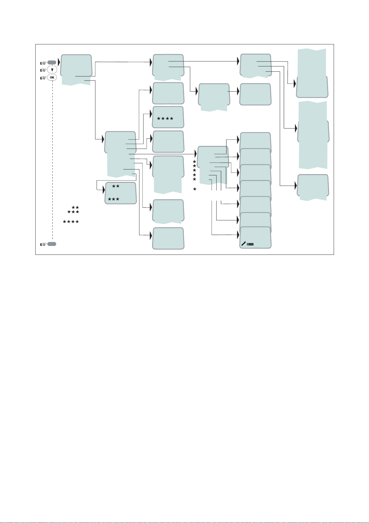
3. HANDSE T FUNCTIONS
MENU
››Sat. Search
Phone setup
Set Network
Ports
Information
››Diagnostics
Traffic log
Forward ld
Version Info
Network Info
Alarms & Msgs
Position
Speed/Course
››
Speed: 0.0
Course: 000
Speed
Course over ground
Note! Not to be used for navigation
Logging mode needs to be set to
print to RS232 in vtLite Traffic Log
ESC
reverts to idle
›› Port A
Port B
COM defaults
NMEA port
›› On
Off
›› Dump trf. log
›› HW(fwd):A98853
IOR Spot: 5
Ready for call
NCSC Curr: 1
NCSC Actv: 0
Registration
SUCCESSFUL
›› Clear Causes
Alarms List
Info Log
›› 010d29m02s E
059d52m11s N
››Driver switch
Speed
Format
Flow control
››System
Ctrl SW
DSP
Monitor
KDB
RFB
ATB
Only appears with
Diagnostics On
›› Speed
Format
Flow control
›› RS-232
RS-422
REL 2.0
18 Nov 2004
103226 Ver: 2.0
17 Nov 2004
1.9.2
1.05
1.30
1.00
Type: 241.00
1200bps*
2400bps
4800bps
9600bps
19200bps
38400bps
57600bps
›› 115200bps
d=7,p=none,s=1
d=7,p=e,s=1
d=7,p=0,s=1
d=7,p=m,s=1
d=7,p=s,s=2*
›› d=8,p=none,s=1
d=8,p=e,s=1
d=8,p=0,s=1
d=8,p=m,s=1
d=8,p=s,s=1
d=8,p=none,s=2*
d=8,p=e,s=2*
d=8,p=0,s=2*
d=8,p=m,s=2*
none
›› rts/cts
xon/xoff trans
xon/xoff
›› default settings
*: Can not be used.
3-2
Page 29
3.2 Satellite search
Some geogra phic locations allow contact with more than one Ocea n Region
satell it e. It is recommended to choose an Ocean Region pro vi ding good signal
quality and c ost-effective communi c ation.
Use the Satellite Coverage Map on next page to select the O c ean Region at
your loc ation:
Atlantic Ocean Region West: AOR-W
Atlantic Ocean Region Eas t: AOR-E
Pacific Ocean Region: POR
Indian Ocean Region: IOR
Regions 4-7 ar e not in use.
To select ano t her Ocean Region:
3. HANDSET FUNCTIONS
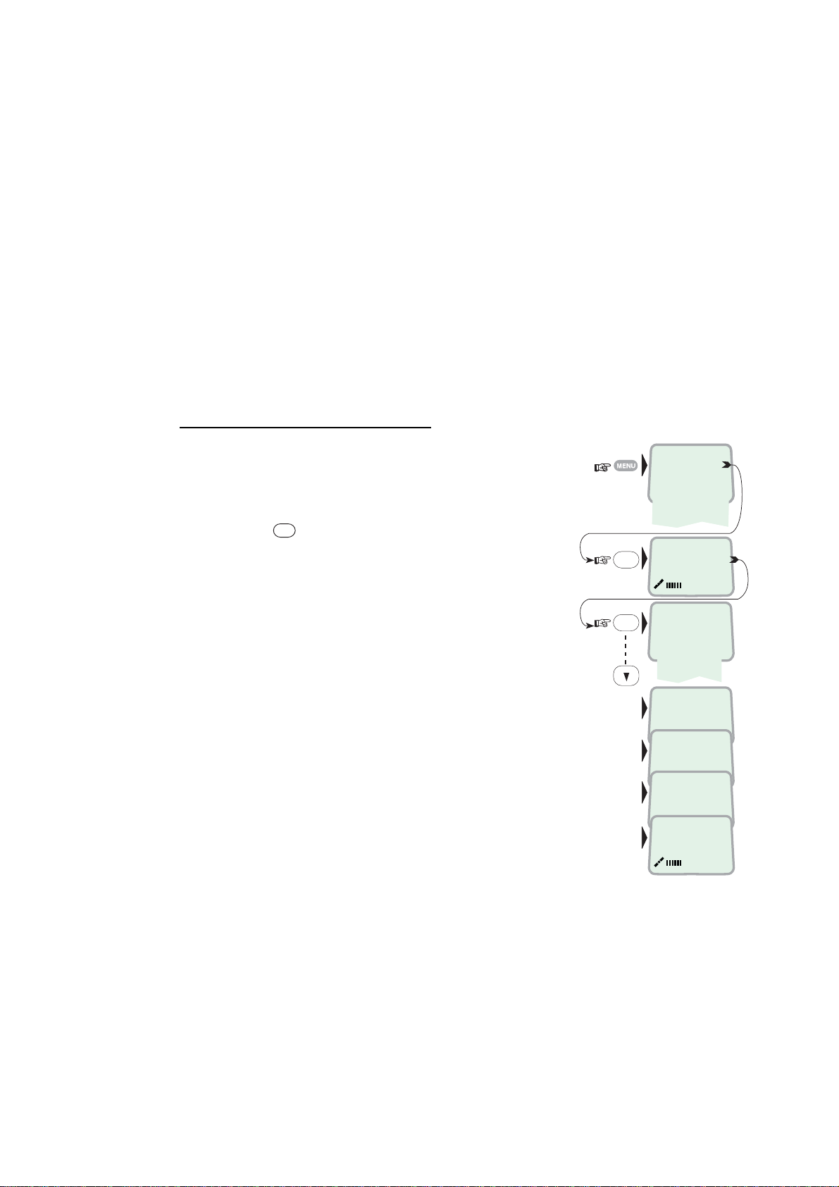
1 Open the MENU and press Sat. Search.
OK
Pressing
opens the list o f searching
alternatives.
2 Select as r equired.
When selecting Sear ch all, the antenna searches
one Ocean Region after the other until a satellite
signal is found.
When s electing a specific Oc ean Region (AOR-W,
AOR-E, POR or IOR) the system knows the
elevation and will find the satellite fast if visible.
The antenna performs an hemispheric search at
antenna elevation angles varying within 0°
through 90°.
OK
OK
››Sat. Search
Phone setup
D
Set Network
Ports
+
Information
''
Opening Search
Search all
››
AOR-W
AOR-E
POR
IOR
Searching...IOR
Elevation 0
Tuning to IOR
Elevation 17
KDD IOR
Logging on
KDD IOR
Ready for call
3-3
Page 30
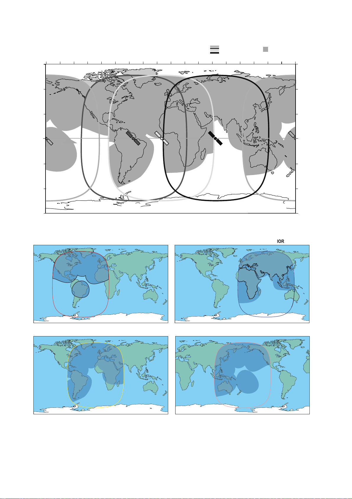
3. HANDSET FUNCTIONS
60 N
30 N
LATITUDE
0
30 S
60 S
5°
POR
178 E
Equator
Elevation
LONGITUDE
140 W 120 W160 W 40 E 60 E
AOR-W
54 W
Elevation
5°
20 W 0 20 E80 W 60 W 40 W100 W180 W
Elevation
5°
AOR-E
15.5 E
IOR
64.5 E
5°
Global beam
80 E
Elevation
(circles)
100 E 120 E 140 E 160 E
Spot beam
POR
178 E
Elevation
5°
180E
60 N
30 N
LATITUDE
0
30 S
60 S
TEL: 870 or 872
Pacific Ocean Region
POR
AOR-W
TEL: 870 or 874
Atalantic Ocean West Region
AOR-E
AOR-W
TEL: 870 or 871
Atlantic Ocean East Region
AOR-E
TEL: 870 or 873
Indian Ocean Region
IOR
POR
TEL: 870 or 872
Pacific Ocean Region
POR
3-4
Satellite Coverage Map
Page 31
3.3 Phone setup (ISDN Handset)
3.3.1 Active MSN (Multiple Subscriber Number)
When making a call , the device c onnected to FELCOM 50 identifies itself locally
by its MSN number.
The firs t ISDN Handset conn ec ted has the following MSN numbers:
Identit y MSN number Speech quality
01: 20 4.8 k Speech
91: 30 64 k Speech
3.3.2 Keyclick
When activated, a cli c k is hear d when pressing a k ey. T he k eycli c k c an be
turned on/off as follows.
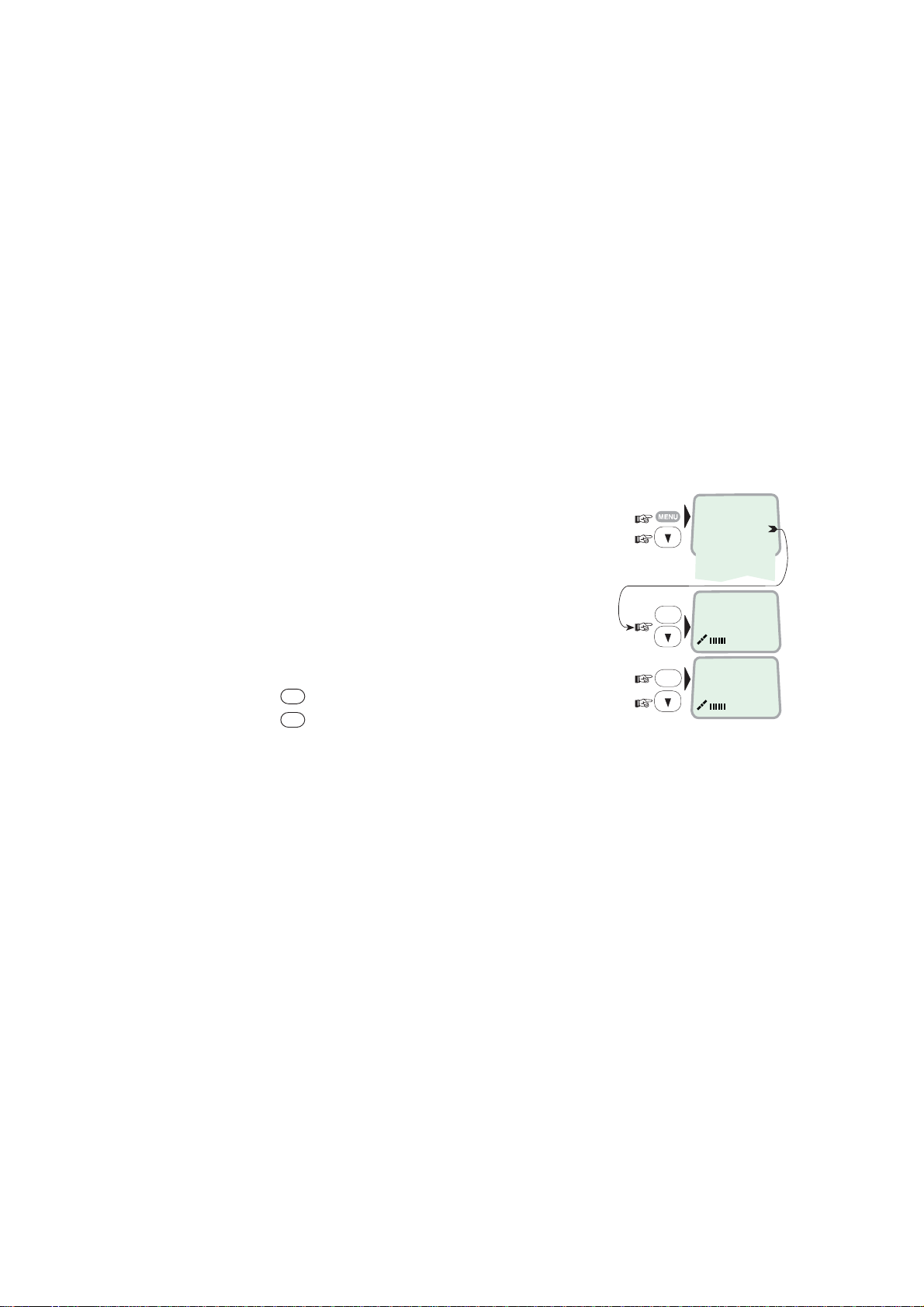
1 Open the MENU and scroll down to Phone
setup.
2 Select the Keyclick functi on.
OK
3 Press
4 Press
and scroll to O n or Off, as required.
OK
to store the sett ing.
3. HANDSET FUNCTIONS
Sat. Search
››Phone setup
Set Network
Ports
Information
››Active MSN
OK
Keyclick
OK
›› On
Off
3-5
Page 32
3. HANDSE T FUNCTIONS
3.3.3 Ringer
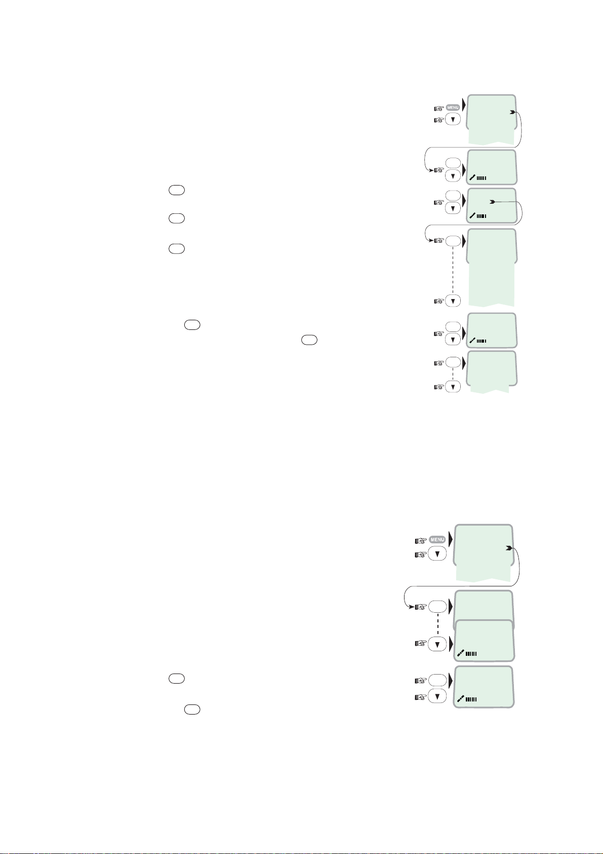
The tone sound and level heard when the phone
rings may be selected as follows .
1 Open the MENU and select Phone setup > Ringer.
OK
2 Press
to select the T one function.
OK
3 Press
again and scroll down to required
tone.
OK
4 Press
to store the selec ted one.
5 Select the Ringer function again and scroll down
to the Volume functi on.
OK
6 Pressing
required so und level, and press
lists the choices. Scroll down to
OK
to store it.
OK
OK
OK
OK
OK
Sat. Search
››Phone setup
Set Network
Ports
Information
Keyclick
››Ringer
››Tone
Volume
›› Tone#1
Tone#2
Tone#3
Tone#4
Tone#5
Tone#6
Tone#7
Tone#8
Tone#9
Tone
››Volume
›› Low
Medium
High
Increasing
3.3.4 Answer beep
FELCOM 50 m ay be set to emit a signal in the handset when an outgoing call is
answered. The signal will also sound when a call is transferred at the remote
end.
The si gnal is not active during handsfree calls.
The answer beep can be turne d on/off as f ollows.
1 Open the MENU and scroll down to Phone setup.
2 Scroll dow n to the Answer beep function.
OK
3 Press
4 Pressing
and scroll to O n or Off, as required.
OK
stores the chosen m ode.
Sat. Search
OK
OK
››Phone setup
Set Network
Ports
Information
››Active MSN
Keyclick
Ringer
››Answer beep
›› On
Off
3-6
Page 33
3.3.5 Backlight On/Off
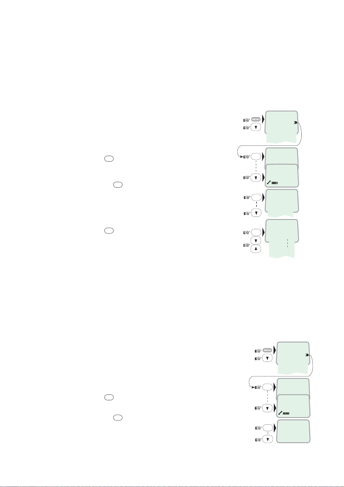
The dis play and keyp ad bac k light can be set to:
• On, permanently ON
• Off, permanently OFF
• 30 seconds ON when pres s ing a key or receiving a call, and stay s ON 30
secs after last event.
• Dimmer, intensity adjustable in 10 steps .
Changing the s etting:
1 Open the MENU and scroll down to Phone setup,
and scroll down to the Backlight function.
OK
2 Press
and scroll dow n to required sett ing.
OK
3 Pressing
at Dimmer opens the backl ight
adjustment window.
Adjust with up/do wn arrows.
4 Press OK to store.
3.3.6 Protocol
3. HANDSET FUNCTIONS
Sat. Search
››Phone setup
Set Network
Ports
Information
OK
››Active MSN
Keyclick
Answer beep
››Backlight
›› On
Off
30 second
Dimmer
Dimmer [100%]
90%
10%
OK
OK
FELCOM 50 allows selec tion between t he followi ng ISDN protocols.
• Euro ISDN for connection t o equipment conforming to the European ISDN
standard (default)
• NI-1 protocol: Not used
Note: All ISDN device and the CU must use the s am e pr otocal.
The check for cur r ent protoco l:
1 Open the MENU and scroll down to Phone setup,
and select t he Protocol function.
Sat. Search
››Phone setup
Set Network
Ports
Information
››Active MSN
OK
2 Press
3 Pressing
and scroll required protocol.
OK
stores the chose n ISDN protocol.
To change the defa ult setting in the CU, see “5.9. 1 ISDN
OK
OK
Keyclick
Language
››Protocol
››Euro-ISDN
Nl-1
protocol configuration” .
3-7
Page 34
3. HANDSE T FUNCTIONS
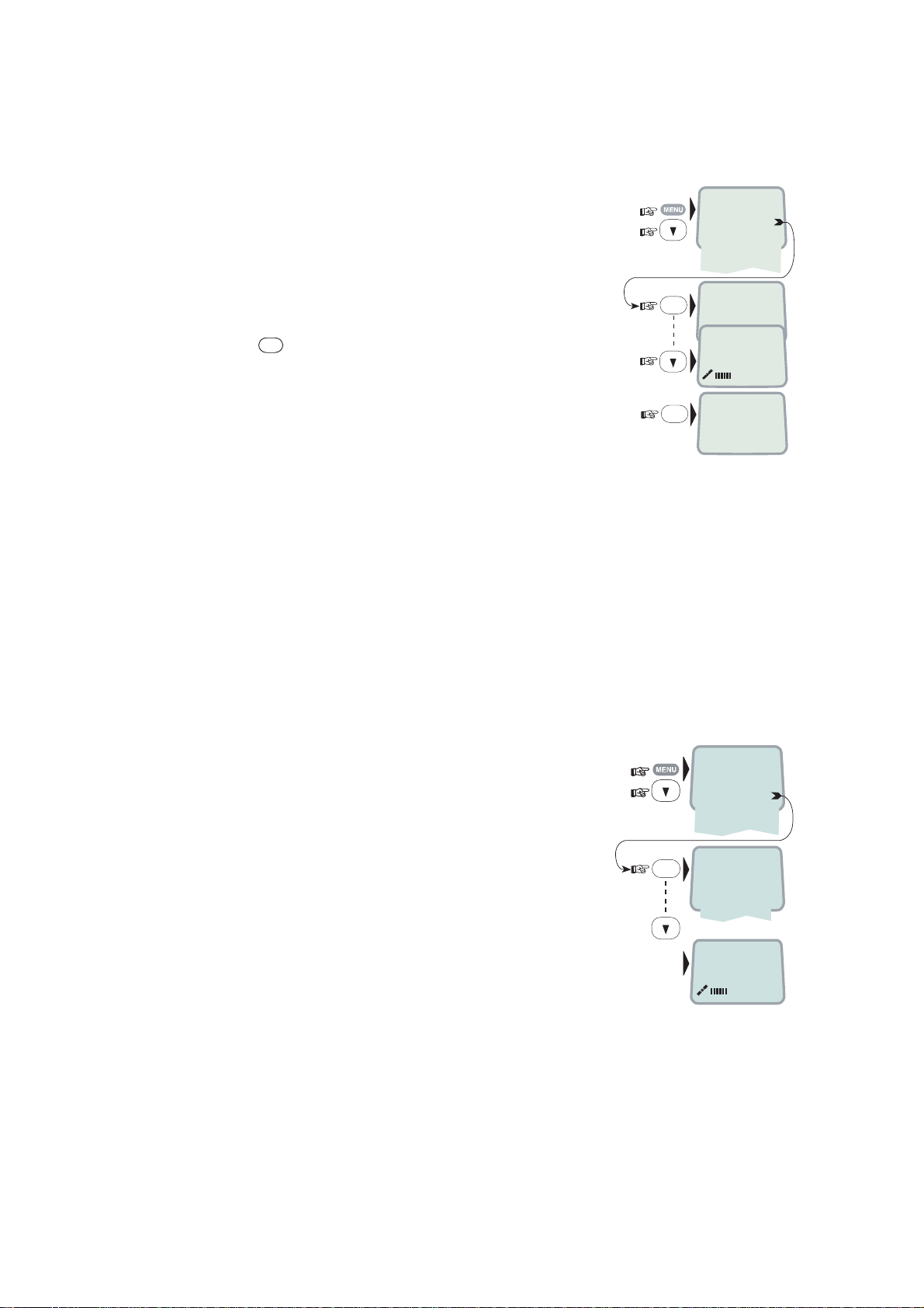
3.3.7 Software version
This func t ion displays the ISDN Handset s oftware version.
1 Open the MENU and scroll down to Phone setup,
and select t he SW version function.
OK
2 Press
to read.
Sat. Search
››Phone setup
Set Network
Ports
Information
››Active MSN
OK
OK
Keyclick
Protocol
››SW version
1.4.00 270103
3.4 Selecting default Net service provider
The default Net service provider for a satellite (Ocean Region) is automatically
used when dialing shi p- to-shore.
When using SI M card, selection of a Net serv ice provider i s r es tricted to the one
stored on the SI M cards!
Changing default Net service provider :
1 Open the MENU and Scroll down to Set Network.
2 Scroll down to the required Net servic e pr ovider.
3 Store the new Net service provider for the
current Ocean Region.
To preprogram Net pr ovider for all Ocean Regio ns ,
“vtLite Mobile” sof tware must be used. See chapter 5.
OK
››Sat. Search
D
Phone setup
Set Network
Ports
+
Information
''
››001/CMC
002/Stratos
004/Telenor
005/OTE
Saving data ....
3-8
Page 35
3.5 Setting ports
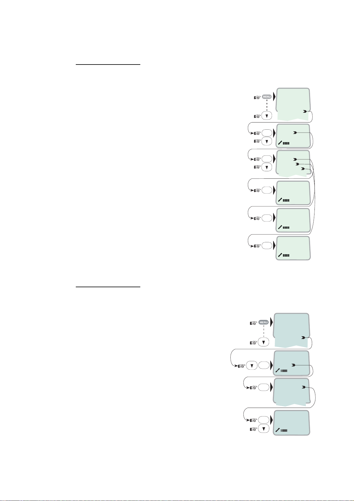
Serial ports A and B
The data speed, format and flow contr ol for the RS-232 serial ports A and B
are set up as follows:
3. HANDSET FUNCTIONS
1 Open the MENU and scroll down to Ports.
See “3.1 Overview” for av ailable choices .
2 Select the parameter to be set for Port A.
3 Select the listed data Speed 115200bps (default).
Note that 120 0 bps can not be used.
4 Select listed format:
8 data bits, no parity and 1 stop bi t ( default)
Note that i tems of “S=2” (s t op bit: 2 bits) can not
be used.
5 Set flow control to rts/cts (default).
Note that “xon/xoff t r ans ” c an not be used.
Port B driver switch
OK
OK
OK
OK
OK
Sat. Search
››Phone setup
Set Network
Ports
Information
››Port A
››Port A
Port B
Port B
››Speed
Format
Flow control
››115200bps
››d=8,p=none,s=1
d=8,p=e,s=1
none
››rts/cts
Select dat a s peed, form at and flow control as described above.
Swit c hing the driver from RS-232B to RS-422:
6 Select Ports, and scroll down to Port B.
7 Open the Driver switch function and
scroll down to RS-422.
OK
OK
The RS-422 terminal bloc k is now activated
for connection of e.g. PC using cables of up
to 100 m.
The RS-232 serial port B i s disconnected.
OK
››Sat. Search
Phone setup
Set Network
Ports
Information
Port A
››Port B
››Driver switch
Speed
Format
Flow control
RS-232
››RS-422
3-9
Page 36
3. HANDSE T FUNCTIONS
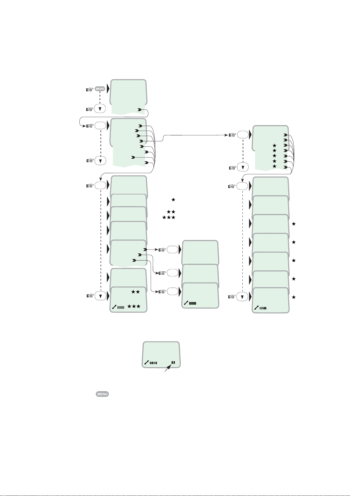
3.6 Information available
Open the menu and scroll dow n to read various informati on, as indicat ed
(examples):
››Sat. Search
Phone setup
Set Network
Ports
Information
››Diagnostics
OK
Traffic log
Forward Id
Version Info
Network Info
Alarms & Msgs
Position
Speed/course
On
OK
Off
››Dump trf. log
HW (fwd): A98853
IOR Spot: 5
Ready for call
››Clear Causes
Alarms List
Info Log
Only appears with
Diagnostics ON
Speed
Course over ground
Note! Not to be used for navigation
1) IFII/03501
OK
Subscriber busy
OK
OK
››System
Ctrl SW
DSP
Monitor
KDB
RFB
ATB
REL 2.0
18 Nov 2004
103226 Ver: 2.0
17 Nov 2004
1.92
1.05
1.30
1) Burst not
010d29m02s E
059d52m11s N
Speed: 0.0
Course: 000
OK
OK
sent
1) No contact
with GPS
1.00
Type: 241.00
Alarm
The alar m indicator flas hes when an alarm cond ition occurs:
Telenor IOR
Ready for call
Alarm indicator
The indicator stops once the alarm has been r ead in the Dis play Handset by
pressing
> Informati on > Alarms & messages.
The indicator continues to be displ ay ed if the alarm condition persists.
The red alarm indicat or on t he CU ( s ee next page) flashes in s t ep with t he alar m
indicat or in the display.
3-10
Page 37
4. OPERATION FROM PC
4.1 Installing the PC program
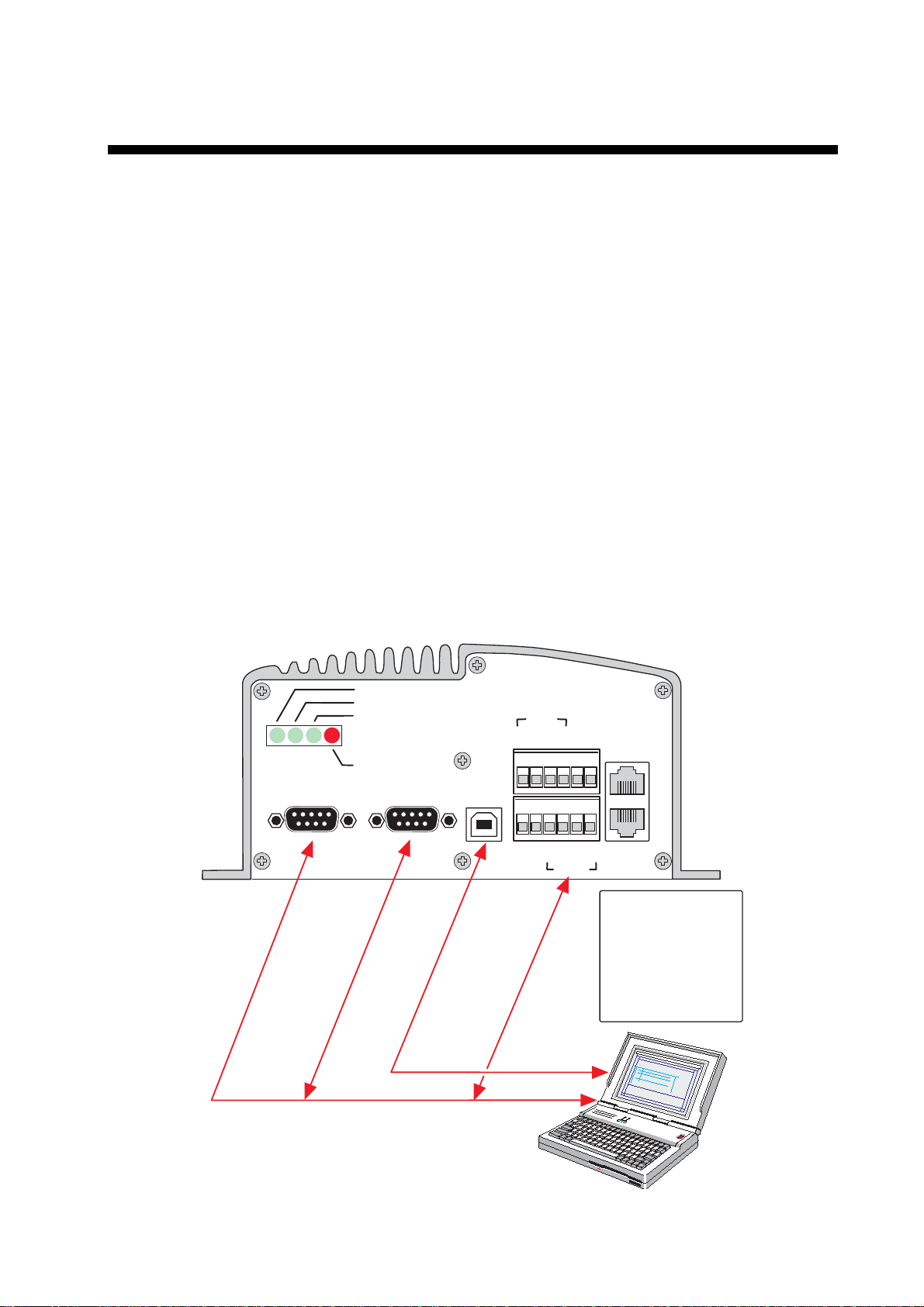
The vtLite Mobile program allows F E LCOM 50 to be operated or configured
from a PC, i nc luding functions such as:
• Phone book
• Traffic log
• Configuration of ports
(ISDN/RS-232/USB/RS422)
• Configuration of the CU
Connect the P C as s hown belpw .
The vtLite Mobile program is available on the enclosed CD and must be
inst alled on the PC hard disk .
For an explanat ion of the funct ions, see lat er in this manual.
Note: To install t he vtLite Mobile, the user name of the PC should be one-byte
characters.
ON
48 VDC
SYNC
ALARM
RS-232 A RS-232 B
5 4 3 2 1
9 8 7 6
5 4 3 2 1
9 8 7 6
USB
Max 100
USB port
PC serial port
ISDN
TX-
TX+
NMEA-
NMEA+
metres
RX-
RX+
TX+
TX-
RS-422
ISDN
ISDN
RX+
RX-
The driver used with
the RS-232 B (DATA)
port can be switched
to be used with the
RS-422 (DATA) port
instead. The switching
is performed with the
ISDN Handset.
DTE
4-1
Page 38

4. OPERATION FROM PC
Procedure:
1 Insert the CD and open it from the “My Comput er” icon.
2 Inst all the “vtLite Mobile” to the PC hard drive.
a. Open the “vtLite 6.2” folder.
b. Double-click the “setup.exe” icon and follow the instruction displayed.
c. Double-click the “furuno.bat” icon.
3 Connect t he s er ial cable bet ween the PC serial port and one of the RS-232
ports on t he FELCOM 50 Communication Uni t. See previous page.
4 Sw itch ON the Communi c ation Unit.
5 Start t he vtLite Mobil e pr ogram by clicking Start>Programs>vtLite Mobile.
If no contact, clic k Mode>Terminal MMI.
6 Click Configure>Port to check the port settings.
7 The USB por t can be used to run vtLite Mobile.
The USB modem dr iver required is accessible on the CD.
4-2
Page 39

4.2 Starting up
• Switch ON FELCOM 50. See fi gure on page 2-2 for location of the ON/OFF
switch.
• Turn ON the PC and click Start>Programs>vtL ite Mobile.
Note: T he vtLite can only be used on one PC at a time.
1 The sat ellite search prog r am is initi alized.
See also "3.2 Satellite search".
4. OPERATION FROM PC
Beam was selected. In global beam, "GLB" is shown.
If spot selection is not complete, SBS is shown as above.
2 FELCOM 50 starts searching for last known satellite/elevation (Ocean
Region) as default.
3 When receiving a satellite signal, a signal strength bar wil l appear in the
search w indow.
The longer the signal bar or higher the signal strength indicator value, the
better the signal quali ty. The maximum marker indicates the hi ghes t signal
strength achieved during t he current se ar c h.
4-3
Page 40

4. OPERATION FROM PC
Note: It is recommended that the si gnal strength reading (S/N=Signal/Noise
ratio) should be at least 550, typically 600. The antenna will automatically
fine-tune to the best signal and accept it.
Clicking Seek starts the search again. If required, select a specific satellite by
clicking New.
See also "5.4 Selecting default Net service provider".
4 The equi pm ent is ready for use when the Main window appears.
S/N ratio
SPT is shown with a spot beam selected.
Main window with “Diagnostic” ON
To make a connection, s ee "2.6 Making a call"
4-4
Page 41
4.3 Phone book
Adding and editing entries can also be done from the handset, see “Chapter 2
OPERATION FROM HANDS E T”.
Phone book capacity
CU SIM card
(Data vary with card ty pe)
Phone number s : 100 entries 100 entries
Number length: 19 digits 19 digit s
Name length: 29 characters 12 charact ers
Entry num ber s: 0 – 99 100 an d up
The SIM c ar d entries and "CU" entr ies merge w hen the card is inserted. The list
is sorted by name.
Abbrevi at ed dialing (p ref ix 23)
4. OPERATION FROM PC
1 Clicking Book opens the Phone book.
1
2 Scroll through lis t
Example: dialing
fetches and sends the telephone number stored under short number entry 10.
2
/ to wanted entry.
2
3 1 0
#
on the analogue telephone or ISDN keypad
4-5
Page 42

4. OPERATION FROM PC
Adding or editing entries
3 Clicking New (window 2 on previ ous page) opens the window used to add an
entry t o the book.
Use Del to mo dify. Save stores the new en tr y.
4 Clicking Edit (window 2 on previous page) opens the window allowing
changes to be made in the Phon e book .
Use Del to mo dify. Remov erases the entry.
Note: The book is also used with t he res triction “Dial from book only”, see
"Restricted dialing set u p" on page 5-13.
Netwk=Net provider
Another Net pr ovider may be selected w hen dialing this num ber from the
phone book. If no selection, the syst em uses the default one.
Terrestrial network
It is possi ble to change Terrestrial network on the selected Net provider
(00 is most common). Call your Net provider for more information.
3
4
4-6
Page 43
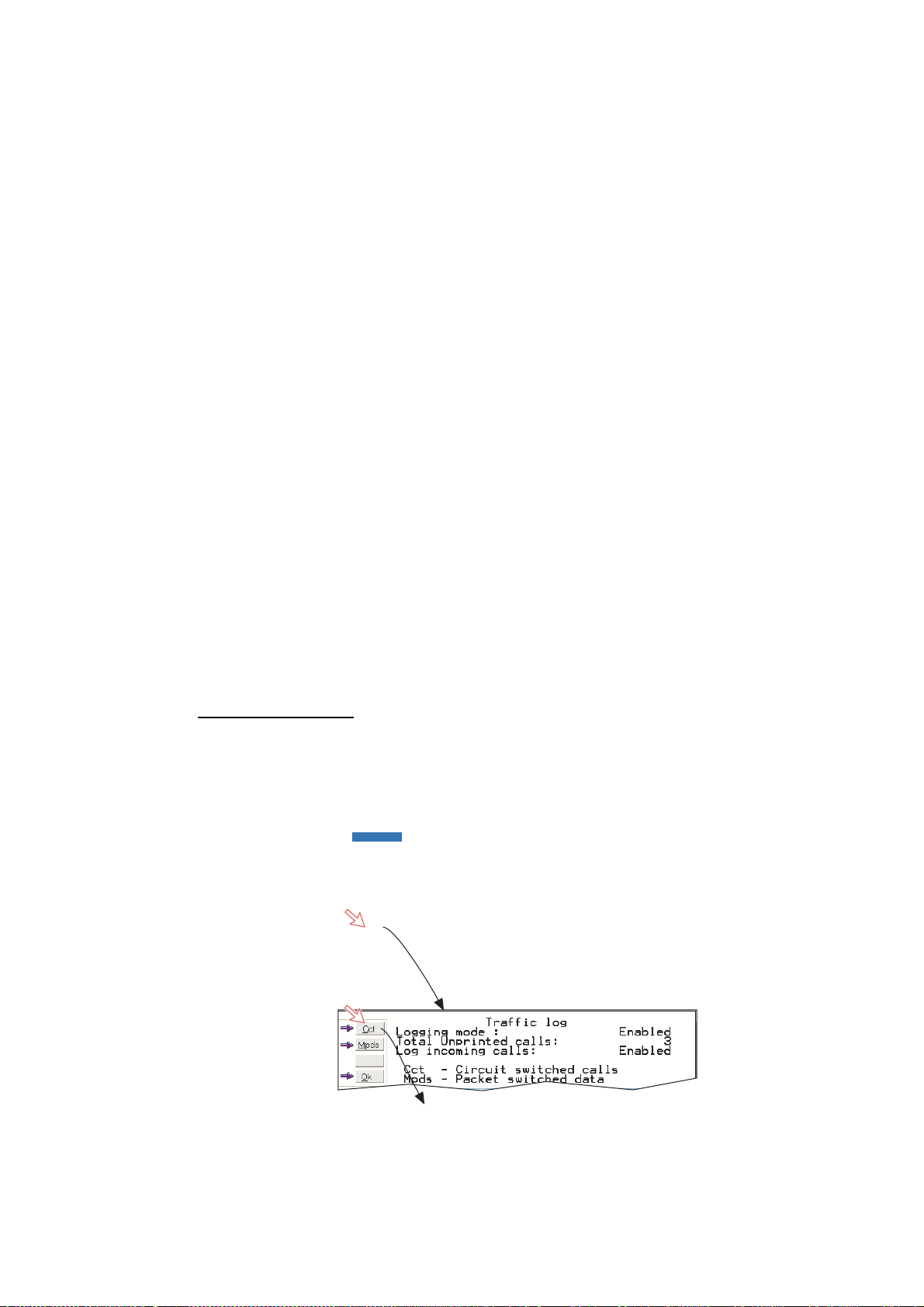
4.4 Traffic Log
This function logs all outgoing and incoming calls both with and without SIM card
inserted. Incoming calls may be logged as well.
Up to 100 calls can be logged.
Circuit switched calls (Cct) including:
• Speech
• fax
• data
Packet switched data calls (Mpds) including:
• Mobile Packet Data Service calls
The FELCOM 50 owner may set the log output mode as follows, (see "4.5
Traffic log settings"):
4. OPERATION FROM PC
• Paused
• Cleared (stops logging and clears the log)
• Enabled
• Enabled & automatic printout to RS-232A
• Enabled & automatic printout to RS-232B
Traffic log readout
1 Clicking Log opens the Traffic log window.
2 The Traffic log window shows whether the logging is enabled, whether
incoming calls are logged, and the total number of unprinted calls (MPDS
and Cct calls).
1
2
(See next page.)
4-7
Page 44
4. OPERATION FROM PC
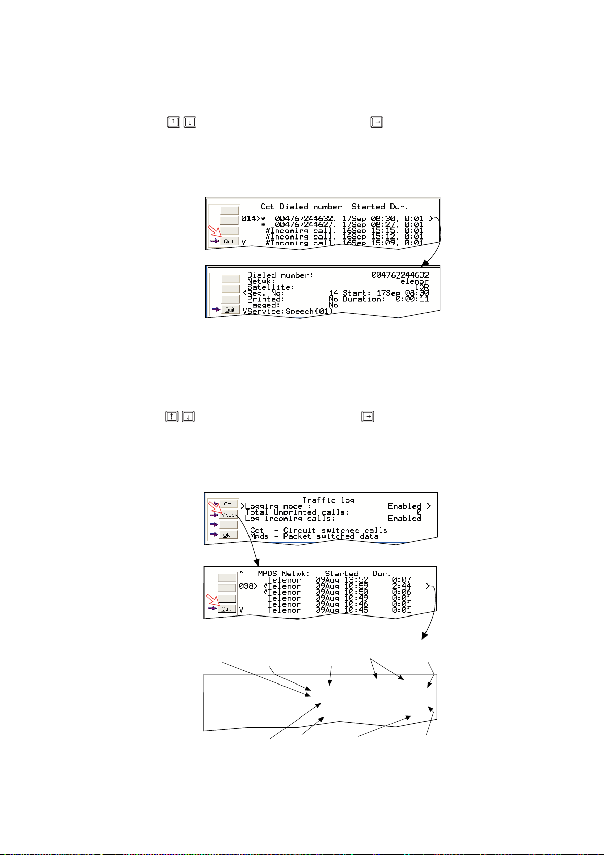
Circuit sw itched calls:
Clicking Cct displays the list of calls.
3 Scroll
selected call.
4 The call details inc lude data such as dialed number, start of the call, durati on,
service and t erm inal I d.
Quit reverts to main window.
/ to wanted cal l record and press to di s play details of the
3
*
Calls not yet printed# Tagged for printout
4
Mobil e P acket Data S ervice calls:
5 Clicking Mpds displays the list of M obile Packet Data Service calls.
6 The call list include data such as Net pr ovider, start of the call and durati on.
Scroll / to wanted call rec ord and press to display details of the
selected call.
7 The call details inc lude data such as f or ward errors in the MP DS system,
forw ar d frames received, etc .
Quit reverts to main window.
5
#
Tagged for printout
4-8
No. of 5 and
20ms slots
used
Peak and average
number of users on
the same channel
Forward errors
in the MPDS
system
Time adjustment
of slot due to
location on earth
Forward
frames
received
Tx/Rx in
Kbyte
Lost
synchronisation
Retransmitted
frames Tx/Rx
direction
Clear cause
level1/level2
Page 45
4.5 Traffic log settings
(owner level only, see "Shifting to owner level" on page 5-4.)
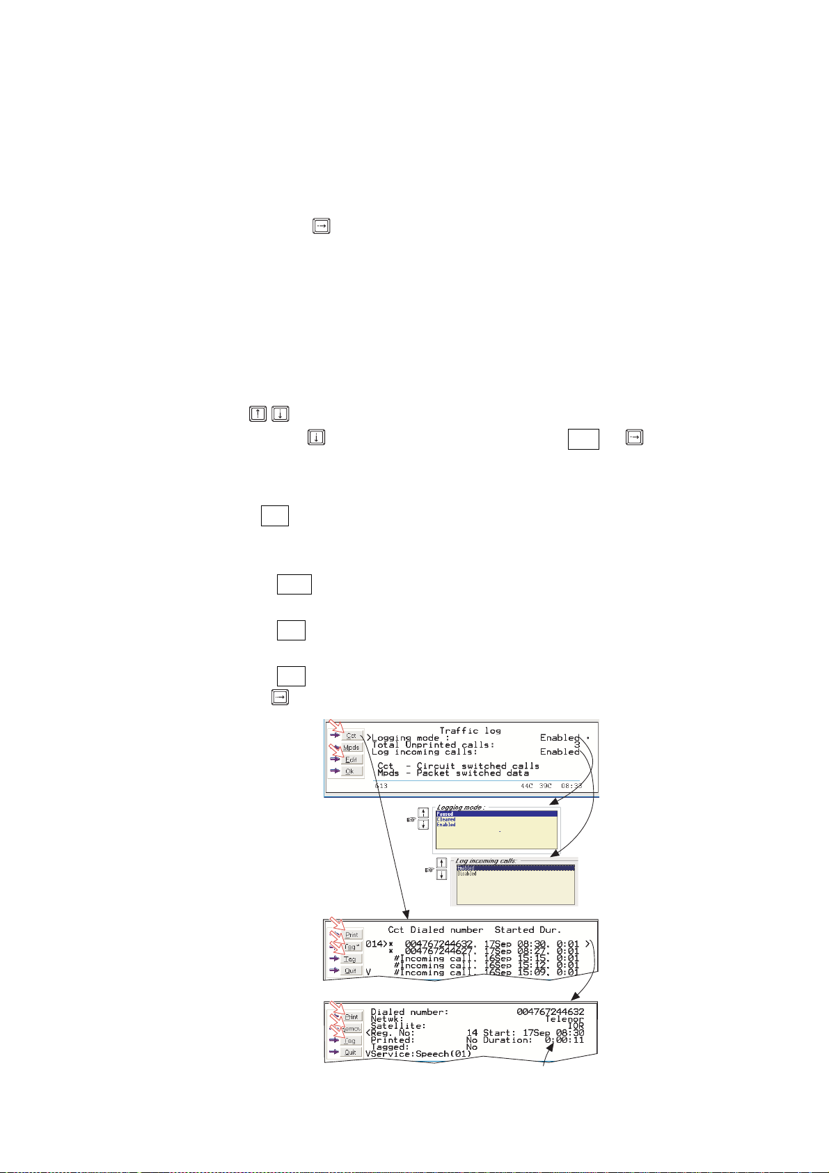
1 In the Main window, clicking Log opens the Traffic log window, which
displays the current log mode, number of unprinted calls, and whether
logging of incoming calls is enabled/disabled.
4. OPERATION FROM PC
• Click Edit or
to open Logging mode window.
• Paused: any logging is off.
• Cleared: all log entries are deleted (incoming and outgoing).
• Enabled: outgoing logging is on.
• Enabled & Automatic printing to RS-232A*: output to local printer
• Enabled & Automatic printing to RS-232B*: output to local printer
Note: If the serial printer is not connected to RS-232A or RS-232B port, do
not choose item marked with
Scroll
/
to wanted mode, and click or press ENTER to select.
• Scroll down
to Log incoming calls and click Edit or
.
*
to enable or
disable logging of incoming calls. Press ENTER to select.
Circuit switched calls:
2 Clicking Cct in the Traffic log (window 1 shown in the figure below) opens the
list of all call records except MPDS calls.
Print outputs all unprinted calls (marked with a star):
• Clicking Tag* marks all calls with a hash, which adds the records to the
printout file.
• Clicking Tag marks the selected call with a hash, which adds the record to
the printout file.
• Clicking Tag again untags a selected record.
3 Pressing
at a record when in window (2) displays detailed call data.
1
Automatic printing to RS-232A
Automatic printing to RS-232B
2
#
Tagged for printout
3
*
Call not yet printed
Hours:minutes:seconds
4-9
Page 46
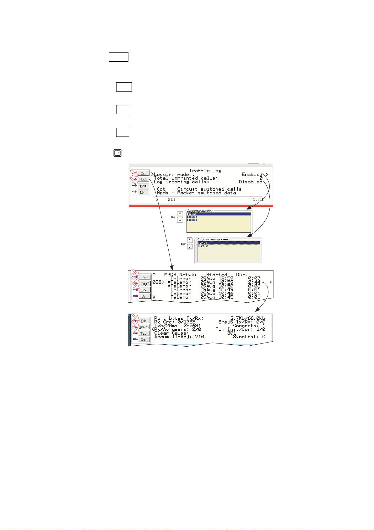
4. OPERATION FROM PC
Mobil e P acket Data S ervice calls:
4 Clicking Mpds in the Traffic log (window 1 on previous page) opens the list of
Mobile Pac k et Data Service call records.
5 Print outputs all unprinted calls (tagged with a hash):
• Clicking Tag* marks all calls with a hash, which adds the records to the
printout file.
• Clicking Tag marks the selected call with a hash, which adds the rec ord to
the printout file.
• Clicking Tag again untags a selected record.
6 Pressing
at a record when in window (5) di s plays detailed call data.
4
5
6
# Tagged for printout
4-10
Page 47

4.6 Traffic log printout viewer
4.6.1 Normal calls (Cct)
The view er lists t agged c all records. Recor ds that have not been printed o ut are
marked w it h a has h. The r ecor d file can be print ed out or saved to disk. For
default setup, see "5.15 Print handling setup".
4. OPERATION FROM PC
Click to save
record file
Click to delete
record file
Ref. no.
#: Record not
printed.
"No hash" when
printed first time.
Number of
records
Click for
printout
Subscriber
number
Type of
service
Start date
and time
Call duration
in minutes
Terminal
ld
MSN
number
and seconds
Ref Dialed number Service Started Duration Term. MSN Net User
114 # 65
115 # 004766779070
116 # 004795437975
117 # 004722225220
118 # 004766779016
119 # 004722225220
120 # 004722225220
127 # 0033297880736
128 # 00870763706017
131 # 004767244621
133 # Incoming call
135 # 004766779070
139 # 004766779070
140 # 004791381198
14 records printed 03. 04. 23 12 : 22 (UTC+02 : 00)
Outgoing calls summary :
Speech : 437 s ( 7. 28 minutes)
9K6 Fax : 63 s ( 1. 05 minutes)
9K6 Data : 5380 s ( 89.67 minutes)
Duration in seconds
per service
9K6 Data
9K6 Data
9K6 Data
9K6 Data
Speech
9K6 Data
9K6 Data
9K6 Data
Speech
9K6 Fax
9K6 Data
9K6 Data
9K6 Data
Speech
030415 20 : 09 0 : 26 21 60 012 Xantic
030421 15 : 54 9 : 17 21 60 012 Xantic
030421 16 : 10 2 : 25 21 60 012 Xantic
030422 14 : 18 11 : 37 22 63 012 Xantic
030422 14 : 30 0 : 32 02 21 012 Xantic
030422 14 : 36 53 : 33 22 63 012 Xantic
030422 16 : 07 0 : 49 21 60 012 Xantic
030422 17 : 00 0 : 54 21 60 012 Xantic
030423 09 : 37 6 : 30 02 21 012 Xantic
030423 10 : 40 1 : 03 11 40 012 Xantic
030423 11 : 35 3 : 17 21 60 012 Xantic
030423 11 : 43 7 : 29 21 60 012 Xantic
030423 12 : 02 3 : 10 21 60 012 Xantic
030423 12 : 16 0 : 15 02 21 012 Xantic captain
Accumulated time in minutes
and 1/100 of a minute
Net
service
provider
User name if
access code
is activated
4-1 1
Page 48

4. OPERATION FROM PC
4.6.2 Mobile Packet Data Service calls (MPDS)
The view er lists t agged c all records. Recor ds that have not been printed o ut are
marked w it h a has h. The r ecor d file can be print ed out or saved to disk. For
default setup, see "5.15 Print handling setup".
Click to delete
record file
Ref. no.
Click to save
record file
Click for
printout
Start date
and time
Call duration
in minutes
and seconds
Net service
provider
Transmitted
data in Bytes
Received
data in Bytes
Retransmitted
frames
#: Record not
printed.
"No hash" when
printed first time.
Total transmitted
files in KiloBytes
B
B
MPDS traffic summary :
Total MPDS Tx : 507KB Total MPDS Rx : 312.4 Sum MPDS : 819.4KB
Total received
files in KiloBytes
Sum of MPDS files
in KiloBytes
B
B
Forward errors in
the MPDS system
Clear cause codes.
000=normal clearing
of connection
4-12
Page 49

4.7 Traffic log output to serial printer
When connect ed, traff ic log det ails are automatically output as indic ated below.
One line is printed out after each call. To dump the traffic log, s elect menu >
informat ion > Traffic log in the ISDN hand s et.
Select logging mode in vt Lite Mobile Traffic log to: A utomatic printing to RS232A
or RS232B, s ee Traffic log setti ngs earlier i n this manual.
4. OPERATION FROM PC
Reference
number
Subscriber
number
Type of
service
Start date
and time
Call duration in
minutes and
1 100 of a minute
Ref
Dialed number
001 004791381198
002 004722225220
003 004766981978
004 0047911381198
005 Incoming call
006 MPDS
007 004722225220
008 004766981978
009 004791381198
010 MPDS
10 records printed 03 . 06 . 16 11 : 26 (UTC + 02 : 00)
Outgoing calls and MPDS traffic summary :
Speech
64K Speech
3.1KHz Audio
64K Data
9K6 Fax
Total MPDS Tx
Total MPDS Rx
Sum MPDS
: 83 s ( 1.38 minutes)
: 12 s ( 0.20 minutes)
: 31 s ( 0.52 minutes)
: 270 s ( 4.50 minutes)
: 32 s ( 0.54 minutes)
: 521.5KB
: 997.0KB
: 1632.0KB
Service Started
Speech
64K Dat
3.1 Aud
Speech
Speech
MPDS
64K Dat
9K6 Fax
64K Spe
MPDS
030616 07 : 10 0 : 19 20 004Tel
030616 07 : 14 1 : 26 60 004Tel
030616 07 : 23 0 : 52 42 004Tel captain
030616 07 : 26 0 : 06 21 004Tel
030616 07 : 27 1 : 03 20 004Tel
030616 07 : 45 1407KB 004Tel
030616 07 : 47 3 : 14 63 004Tel
030616 09 : 30 0 : 54 40 004Tel
030616 09 : 45 0 : 20 30 004Tel
030616 11 : 26 112.5 004Xan
Transmitted &
received data
in KiloBytes
Duration
Tx+Rx MSN Net
MSN
number
Net
service
provider
User name if
access code
is activated
User
4-13
Page 50
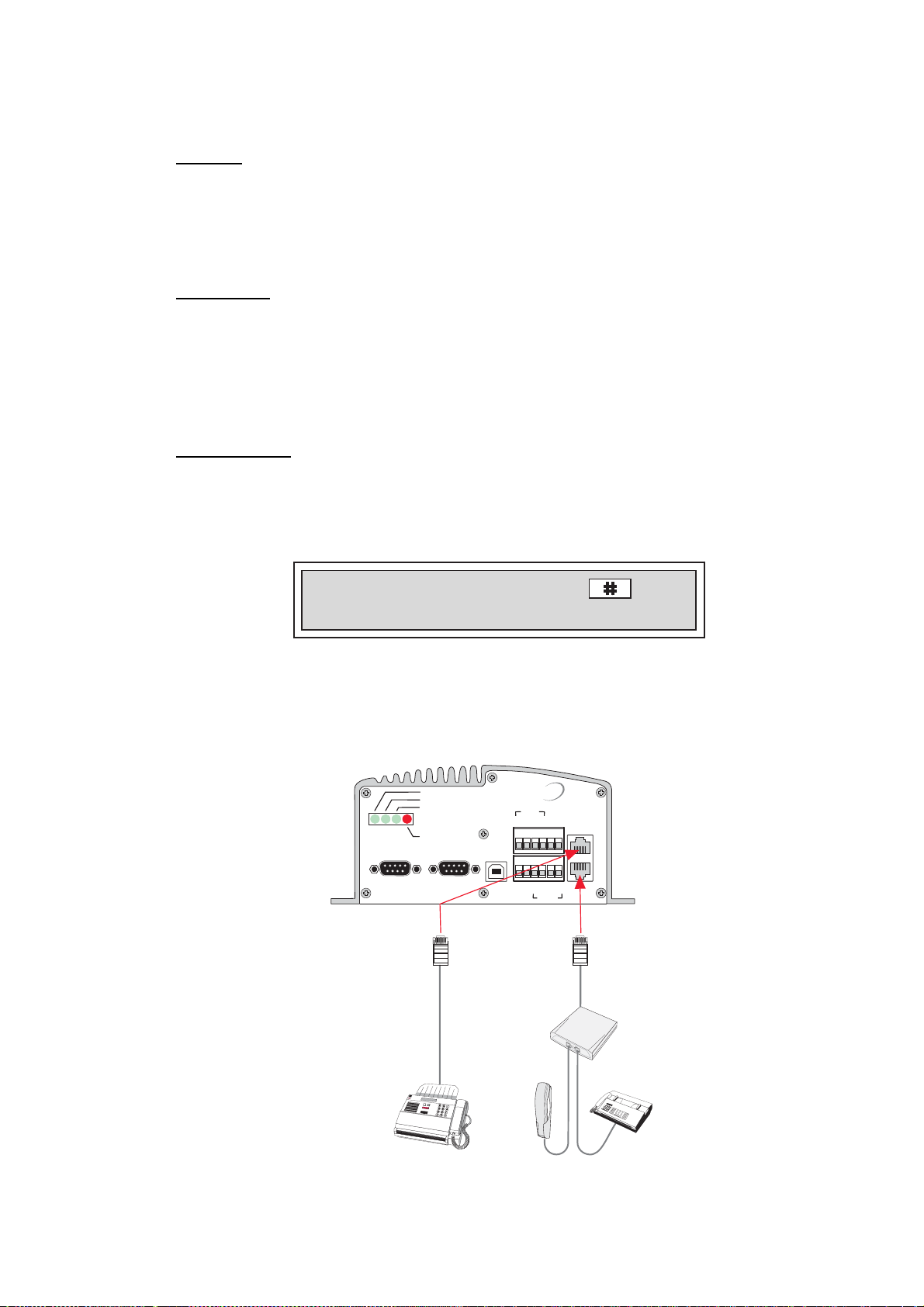
4. OPERATION FROM PC
4.8 Telefax service
General
FELCOM 50 pr ovi des access to telefax service
• Group4 fax at 64 kbps via the ISDN connector
• Group3 fax at 9. 6 k bps via the Terminal Adapter
• Group3 fax usi ng 3.1 kHz Audio ser vi ce
Limitations
FELCOM 50 is fully comp atible with t he world’s leading t elefax machines and
telefax s oftware standards. However , transmission may not be possible thr ough
some of the telefax machines avail able on the market. Please check with your
Net servic e provider/ FURUNO Distributor before purchasing a telefax for use
with FELCOM 50.
Transmission
Telefax calls made by FELCOM 50 are telefax only. Any telephone handset
connected t o the telefax machine can not be used.
To send a fax, use t he s am e dialing sequence as when mak ing a call. S ee "2.12
Various call procedures" earlier in this manual.
Note! On a telefax with keypad, enter as the
last digit before starting transmission.
The 9.6 kbps telefax transmissions norm ally t ake 1 minute per standard text
page using standard resolution. Using superfine or halftone resolution will double
the transmi s s ion time. To save time, avoid using a separat e c over page.
If a call failure should occur while sending a multi-page document, re-send only
the failed pages.
ON
48 VDC
RS-232 A
5 4 3 2 1
9 8 7 6
FELCOM50 CU
SYNC
ALARM
RS-232 B
5 4 3 2 1
9 8 7 6
USB
ISDN
TX+
NMEA-
TX-
RX+
NMEA+
TX-
RS-422
RX-
ISDN
ISDN
TX+
RX-
RX+
Terminal
Adapter
4-14
Digital
telefax(G4)
Analogue
telephone
Analogue
telefax(G3)
Page 51
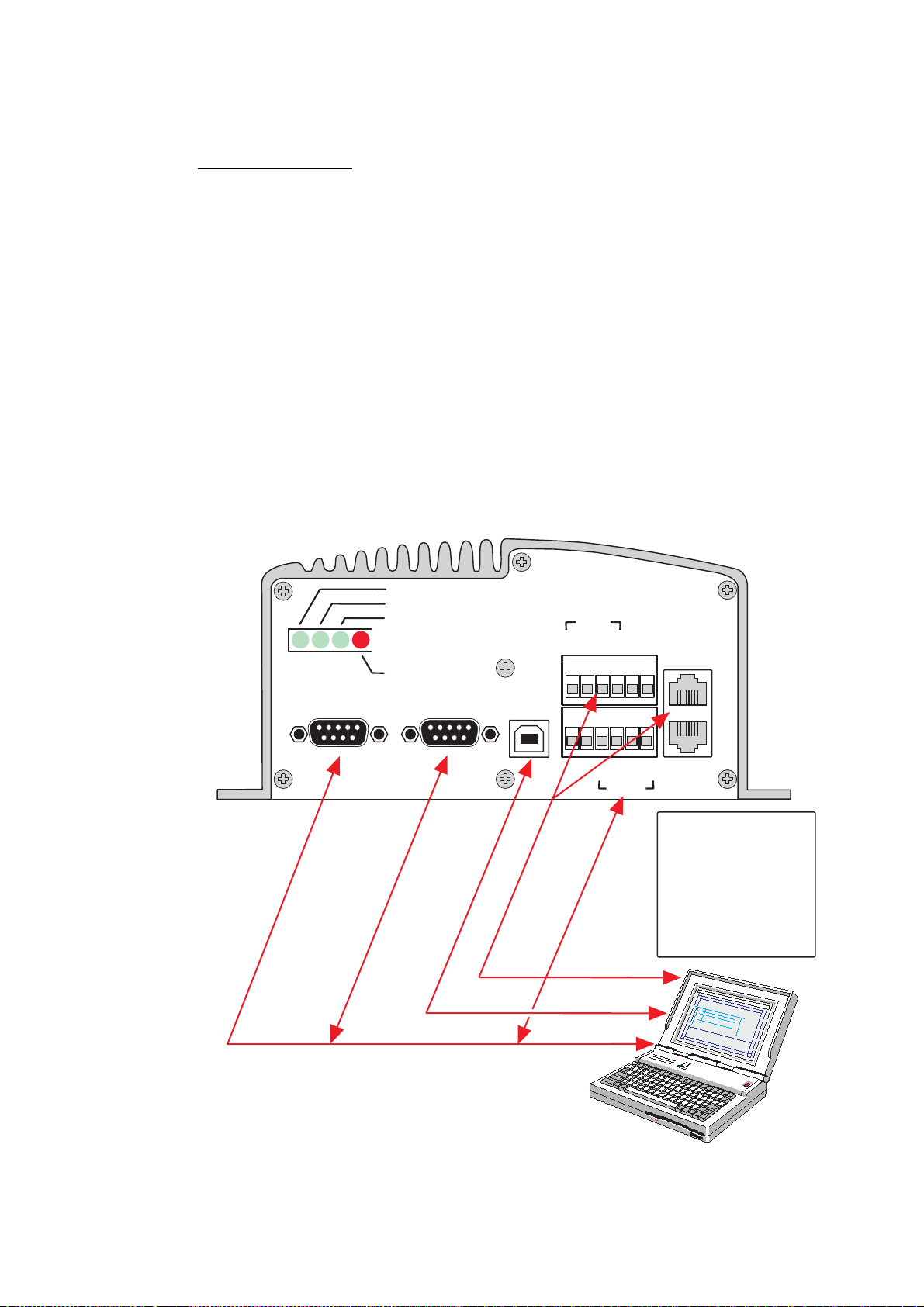
4.9 Data service
Data transmission
FELCOM 50 pr ovi des access to the international IS DN/PSTN networ k data
services t hr ough its built-in modem c apability.
The servic e is suitable for applic ations such as hi gh- s peed file transfer, video,
e-mail and internet.
The transmission rate over the satellite is 64 kbps, and any standard PC w ith a
serial por t c an be us ed.
Ports s uppor ting 64 kbps data service (UDI):
• RS232A
• RS232B/RS422
• USB
• ISDN
For connecting up and configuration, s ee c hapter 6.
4. OPERATION FROM PC
ON
48 VDC
SYNC
ALARM
RS-232 A RS-232 B
5 4 3 2 1
9 8 7 6
5 4 3 2 1
9 8 7 6
USB
Max 100
PC ISDN card
USB port
PC serial port
ISDN
TX-
TX+
NMEA-
NMEA+
metres
RX-
RX+
TX+
TX-
RS-422
ISDN
ISDN
RX+
RX-
The driver used with
the RS-232 B (DATA)
port can be switched
to be used with the
RS-422 (DATA) port
instead. The switching
is performed with the
ISDN Handset.
DTE
4-15
Page 52

4. OPERATION FROM PC
This p age is intentionally left blank.
4-16
Page 53
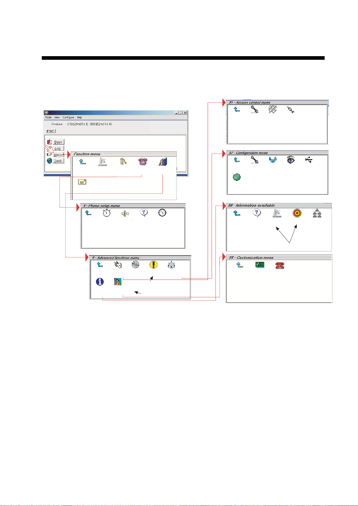
5. CONFIGURATION FROM PC
5.1 Menu functions
Point at icons and double-click the mouse to open menus and f unctions.
Exit Menu
Mail*
Exit Menu
1. Set default**
Net provider
Lock
*
2. Call
duration guard
Exit Menu
8. Information
available
2. Set access
level
7. Message
indication
1. Access
control
9. Customize
9. Advanced
4. Phone
setup menu
3. MPDS Call
Waiting
3. Soft ware
update prep.
functions
4. Set time
4. Alarms
and messages
Only appears when
Diagnostics is ON
Only appears in OWNER level.
zone
7.
Configuration
Exit Menu
Exit Menu
9. Spot Beam
Report Method
Exit Menu
Exit Menu
1. Restrict
dial
1. ISDN
configuration
2. Misc.
version Id
information
1. Paid
functions
2. Access
code
2. Net service
providers
3. Transceiver
Status
Only appears when
Diagnostics is ON
2. Phone
name setup
3. Restrict
SIM usage
4. Set
diagnostics
4. EIRP table
6. USB
9. Network
status information
*: "Mail" is not in use.
**: This icon is not displayed when using SIM card.
5-1
Page 54

5. CONFIGURATION FROM PC
5.2 Function reference list
Reference number for direc t selection. Click menu i n main window and then key
in the num ber.
Ref. Function Features
1 Set default Net provider Allows changing Net service provider (and terres trial network).
See "3.4 Selecting default Net service provider".
2 Set access level Allows shifting between user level and owner lev el, changing P IN
code and owner password. S ee "5.3 Access level".
4
42
43
44
47
9
91
91 1
912
913
93
94
97
971
972
974
976
979
98
982
983
984
989
99
991
992
Phone setup menu
Call duration guard
MPDS Call waiting
Set time zone
Message indication
Advanced functions menu
Access control menu
Restrict di al
Access code
Restrict SIM usage
Software update prep.
Alarms and messages
Configuration menu
ISDN configuration
Net service provid ers
Set diagnostics
USB
Spot beam report method
Information avail able
Misc. version ld i nformation
Transceiver status
EIRP table
Network status information
Customization menu
Paid func tions
Phone name setup
Sets maximum call duration f or 64 k bps calls.
Calls may be received during an M P DS session.
Sets time zone.
Switches indication of received call on/off.
See "5.6 Advanced functions".
Only allows calls from Phone Book. List of barred numbers may be established.
Set personal codes for using FELCOM 50.
Only allows calls with specific card, no card or any card.
Prepare software update.
See information on c hapter 7.
Chooses between ISDN pr otocols.
Changing Net service prov ider data.
Allows additional system information to be displayed
Choose single port or dual port for USB operation.
Sending spot ID or position
See "5.6 Advanced functions".
Displays a series of v ersion inf or m ation windows.
Displays max/m in v oltages and temperatures in RF unit
Carrier status (not in use)
Displays various net work status information.
See "5.6 Advanced functions".
Not in use
Allows alteri ng the phone name.
5-2
Page 55
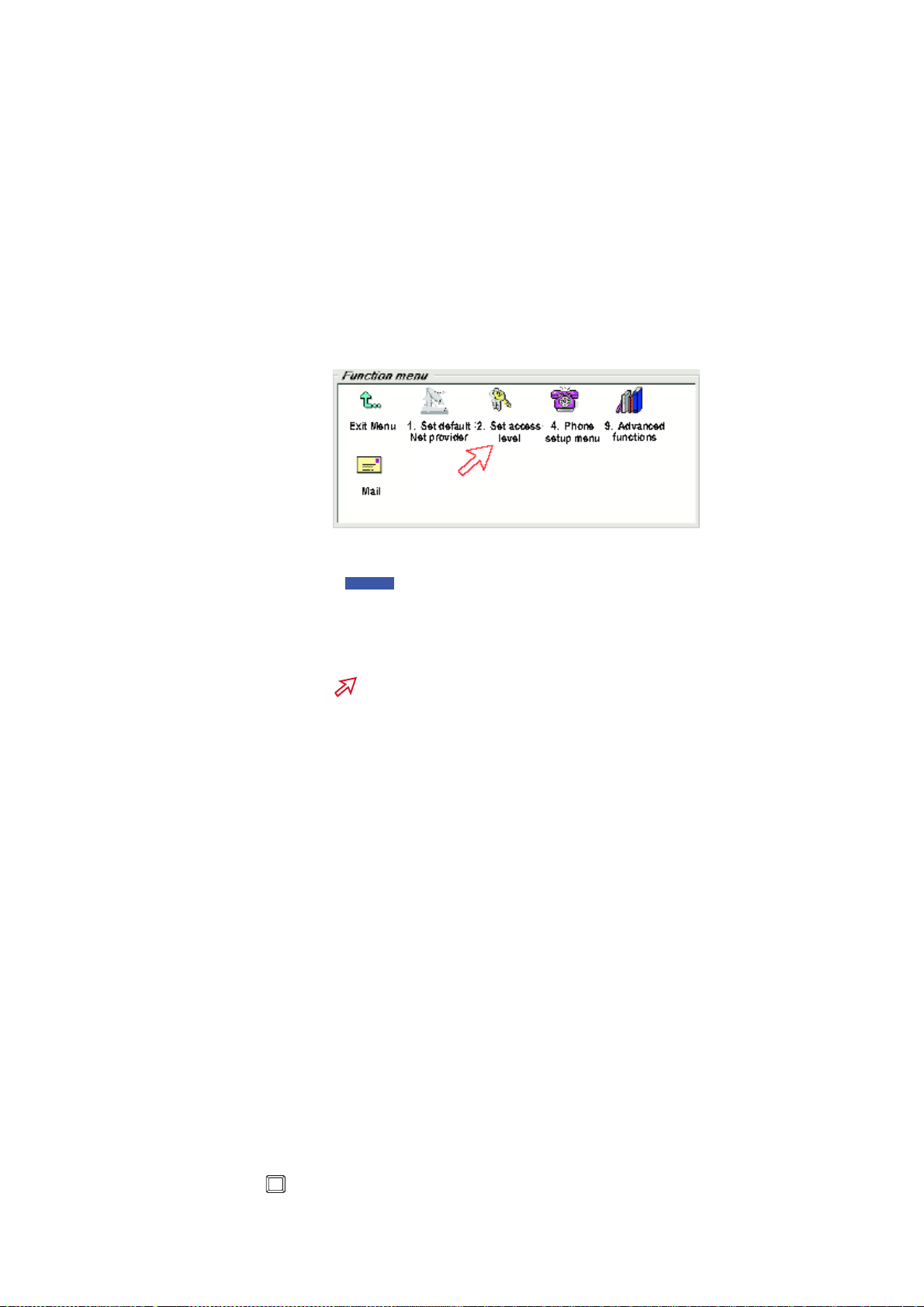
5.3 Access level
The FELCOM 50 user program (vtLite Mobile) is accessible f r om two levels:
• USER LEVEL
• OWNER LEVEL – accessed by owner level password.
Warning: To prevent misuse, passwords other than default must be enter ed
before putting the FELCO M 50 in operation.
5.3.1 Activatin g/Changing user PIN co de
1 Double-click the Set access level icon on the Function menu.
1
5. CONFIGURATION FROM PC
2 Click Edit to enter/modify the PIN code.
2
3 Key in:
• Old PIN code (default: 1234)
• New PIN c ode ( 4-10 digits possible)
• Retype to confirm
Click Ok for each entry and to store new code.
3
Note: Clicking Ok without ent er ing any numbers f or New PIN and Retype new
PIN disables the PIN code.
Note: The Old PIN code must be enter ed to reacti vate the previous P IN code.
Note: If the PIN is ac c identally los t, it is possi ble to reset the user’s pas s word to
default (1234) by logging in as owner:
*
"
+ owner’s password" (Resetting is not possible on SIM car d.)
5-3
Page 56

5. CONFIGURATION FROM PC
5.3.2 Functions requiring owner level
Programming of the funct ions below requires that the us er ac c es s is set to
OWNER LEVEL:
• Traffic log settings/ pr intouts
• Modifying password
• Net Service provider names
• Restricted dial
• Restricted SIM us age
• ISDN configuration (except dat a/time el em ent)
• Access code
• Paid functions
• Phone name setu p
• Spot beam report m ethod
Shifting to owner level
1 Click Owner in Set access level window.
1
2 Key i n the password.
Note: The default password is “1 2 3 4 5 6 7 8 9 0.” Clic k ing Ok activates
the O wner level .
2
5-4
Page 57

5. CONFIGURATION FROM PC
Changing owner level password
3 Open the Set access level window agai n, and c lick Edit to modify the owner
password. Key in:
• Current p as s word
• New password (10 - 12 digi ts)
• Retype to confirm
3
SBS COM1
43C
33C
4 Click Ok for each entry and store new password.
To revert to User level, open the "Set access level" window and click User.
5-5
Page 58

5. CONFIGURATION FROM PC
5.4 Selecting default Net service provider
The default Inmarsat Net service provider for a satel lite (Ocean Regi on) is
automatic ally used if the user does not select another one when making a call.
Make sure t hat you choose the Net s ervice provider who commissioned the
equipment . You will otherwise be barred or charged addit ional rate. In this menu
default Net s ervice provider can be preprogramm ed for the current Ocean
Region.
When using SI M card, selection is automatic ally restricted to one of the allowed
Net servic e prov iders and do es not need to be programmed!
Procedure:
1 On the Function menu, double-click the Set default Net provider icon to
display the current selec tions.
1
SBS COM1
Scroll up/down to change satellite: /
2
.
2
Position: 059d52m12s N 010d29m01s E
Edit
Selct
Ok
SBS COM1
Satellite
POR
IOR
003
Region 4
Region 5
Region 6
Region 7
511 43C 37C 10 : 20
Default Net provider
012 Xantic
022 Xantic
MES category blocked.
MES category blocked.
MES category blocked.
[UTC+02:00]
3 Clicking Selct or pressing/opens the wi ndow promting you to confir m the
choice of satellite with the current default Net servi c e pr ovider.
To change default Net ser v ice provi der for a satellite r egion, see next page.
3
Position: 059d52m12s N 010d29m01s E
5-6
Yes
Use IOR as new satellite?
No
502 43C 37C 10 : 22
SBS COM1
[UTC+02:00]
Page 59

Clicking Edit or pressi ng
4
at the satellite region sel ected in step 2,
displays the list of available Net service provider s .
4
5. CONFIGURATION FROM PC
SBS COM1
5 Scroll to required Net pr ovider:
/
, and press
R
to enter chosen Net
as default.
Save stores the selected Net provider for this sat ellite (Oc ean Region).
5
SBS COM1
6 Click Yes set s Net service provider for all satellites ( Ocean Regions).
6
Position: 059d52m12s N 010d29m01s E
Yes
Do you want the selected net service
provider to be default for the other
satellites as well ?
No
509 43C 37C 13 : 45
SBS COM1
[UTC+02:00]
5-7
Page 60
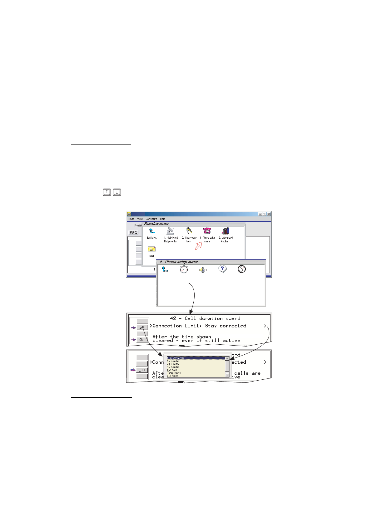
5. CONFIGURATION FROM PC
5.5 Phone setup
This phone set up menu includes the funct ions:
• Limitation of c all duration
• Setting time zone
• Indication of received calls(See next page.)
Double-click the Phone setup menu icon in the Function menu to access the
functions.
Call duration limit
The call dur ation guard prevents accidental transmission of prolonged 64 kbps
calls. The timer sets the point at which the call is automatically cleared.
1 Double-click the Call duration guard icon.
2 Click Edit to set the timer.
3 Scroll
/
between 15 m inutes and 12 hours) , and cli c k Selct to store the setting.
to select the required limit (either “Stay connected” or in steps
1
2
3
MPDS call waiting
SBS
Exit Menu
2. Call
duration guard
7. Message
indication
3. MPDS Call
Waiting
data calls are
4. Set time
zone
5-8
The MPDS c all waiting is t o notify the presence of a fixed-or iginated routine
priority voice or SCPC dat a c all to a di aled-MES that is engaged in an on going
MPDS call. Support for c all waiting allows a user to remai n c onnec ted to the
MPDS network without worrying about mi ss ing a call.
The default is “di
sabled”. If enabled, calls may be received during an MPDS
session. Accepting such calls ends the MPDS session. Note that the cal l waiting
functionality must be implemented on the LE S .
Page 61
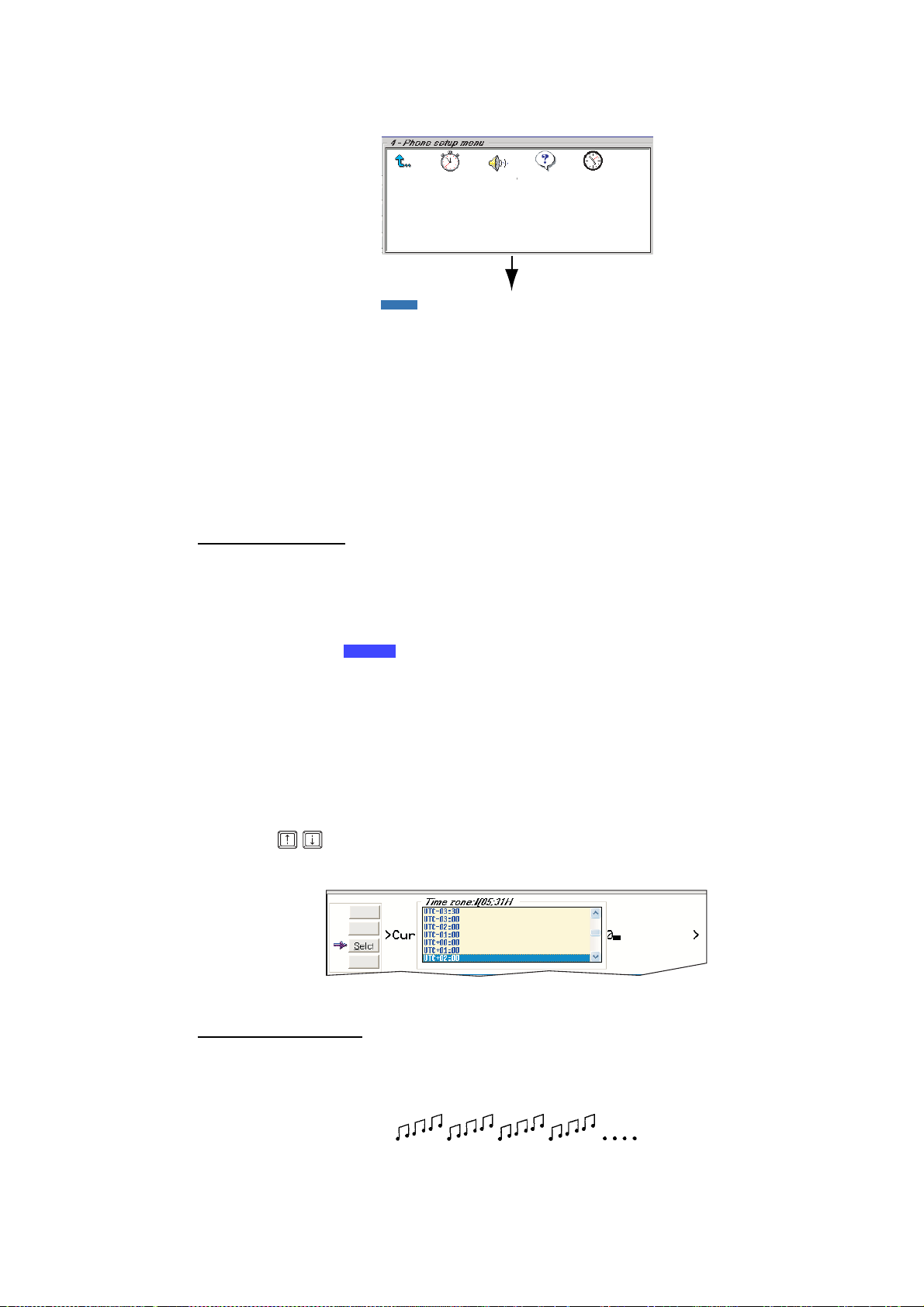
1 Double-click the MPDS Call Waiting icon.
5. CONFIGURATION FROM PC
Exit Menu
2. Call
duration guard
7. Message
indication
3. MPDS Call
Waiting
4. Set time
zone
2 Click t he Enab or Disab button.
3 Click t he Save button to store the setting.
Setting time zone
The function sets the t ime display ed in the windows .
1 Double-click the Set time zone ic on to change zone.
2 Press the Edit button to open the List.
2
SBS
COM1
3 Scroll / to select the required zone. Click Selct to stor e the selected
zone.
Message indication
When the Mas s age Indication functi on is set On, a received data and/or fax call
is signaled in all FELCOM 50 Display Handsets:
5-9
Page 62
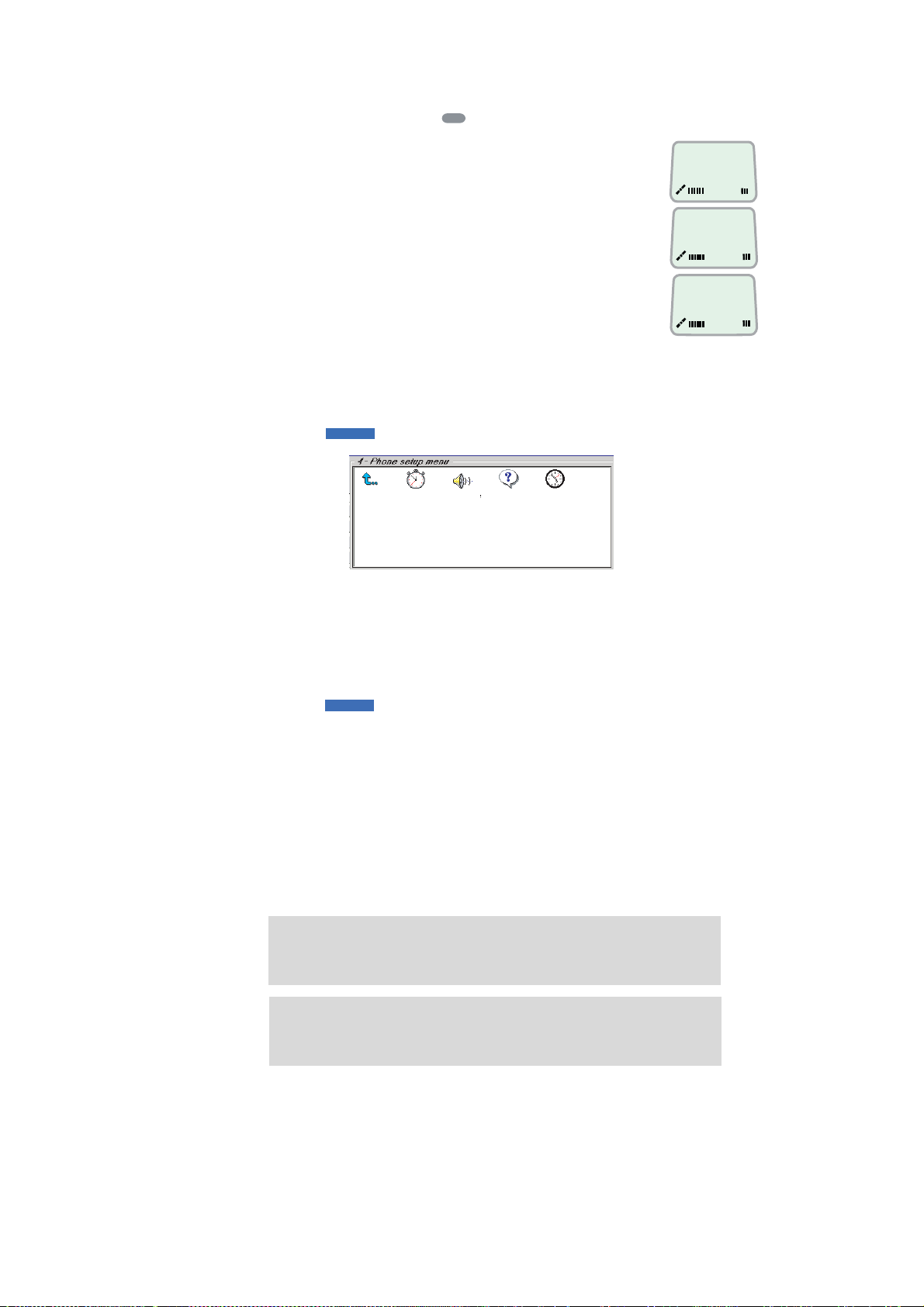
5. CONFIGURATION FROM PC
The ri nging stops when pressing
Call i s finished.
Data call:
Fax call:
(F2M = Fixed-to-Mobile)
When the call is finished, the display reverts to idle.
Setup:
1 Double-click the Message Indication icon in the Phone setup menu.
1
ESC
, or when the
F2M data call
Press ESC. . . . . .
F2M fax call
Press ESC. . . . . .
Telenor
Ready for call
4. Set time
zone
SBS
Exit Menu
2. Call
duration guard
7. Message
indication
COM1
3. MPDS Call
Waiting
2 Select Fax or Data and Enable or Disable indication of received messages,
as required.
Press Save to store the settings.
2
SBS
COM1
Default G 3 fax connection is configured on TEL2 on TA (MSN40).
Fax = 9.6 kbps fax or
5-10
3.1 kHz Audio
Data = 64 kbps data
Page 63

5.6 Advanced functions
“9 Customize” is accessi ble from OWNE R LEVEL only. The OWNER LEVEL is
protected by password. For shifting to owner level and assignment of password,
see "5.3 Access level".
“ 4 Alarms and mess ages” is acces s ible when Diagnostics is turned ON.
5. CONFIGURATION FROM PC
SBS
The Advanced functions i nc lude the following menus.
COM1
• Access control: Restrict dial
Access code
Restrict SIM usage
• Software update prep: Prepares software update
• Alarms an d messages: Indicates alarms and messages. See page 7-4 for
details.
• Configuration: Net ser vic e pr ovider names
Set diagnostics
ISDN configuration
USB
Spot B eam Report Method
• Information available: Misc. version Id information
Network status information
(when diagnostics is O N, see "5.9.3 Set
diagnostics")
• Customize: P hone name setup (owner level)
Paid functions
5-1 1
Page 64
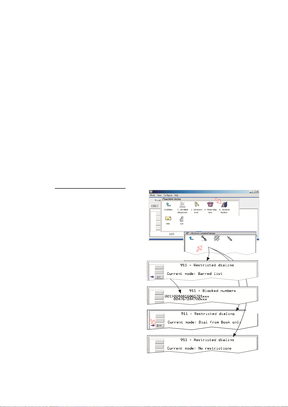
5. CONFIGURATION FROM PC
5.7 Access control
5.7.1 Restricted dialing
The rest r icted diali ng function allows the owner to establish a Barred lis t of
subscriber numbers that cannot be cal led; or set FE LCOM 50 for di aling from
Phone Book onl y. The restrict ed dialing modes pr event misus e of FELCOM 50.
• Barred list, which may contain up to 10 phone numbers or part of numbe rs
that can not be call ed. E.g. the entry "0087" in the barred list prevent s all
mobile-to-mobile calls.
• Dial from Book only, which restricts calls to the numbers in FELCOM 50
Phone Book. It is still possible t o append: an entry with number fiel d " 0047"
means that i t is possible to dial all Norw egian numbers.
When a SIM c ar d is inserted, t he SIM entries will not be merged with the
"phone" entries. The function is active for non-SIM operation and for one
specific SIM card. See "5.7.4 Rest ricted SIM usage".
• No restrictions.
Only one mode can be active at one time, as selected by the owner, see next
page.
Checking t he dialing set u p
Via t he Function menu >
Advanced f u nctions menu,
double-clicking the Restrict dial
icon on the Access control menu
shows the active mode.
• Barred list
• Dial from Book only
• No restricti ons
SBS
Exit Menu
1. Restrict
dial
2. Access
code
3. Restrict
SIM usage
5-12
Alternative
modes
Page 65
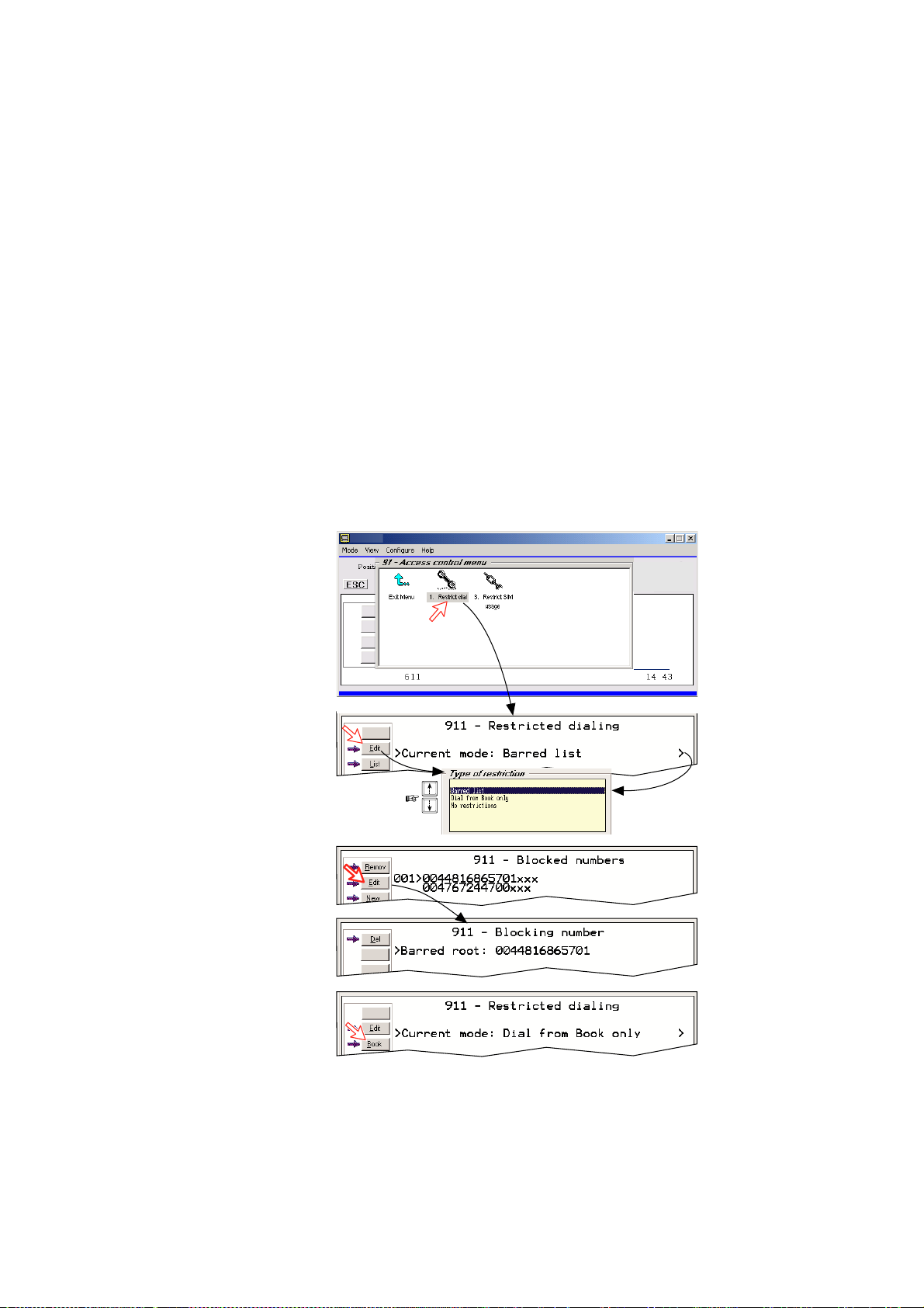
5. CONFIGURATION FROM PC
5.7.2 Restricted dialing setup (owner level only)
"Barred list" and phone book are establ ished as follows:
1 Open the Restricted dialing window as s hown on the previous page.
2 The Restricted dialing window shows which list is currently active.
Edit allows selection of restriction mode. Scroll up/down to select.
(Selct enters the chosen mode)
3 Clicking List displays the blocked phone numbers .
The List key only appears when Current mode is Barred list.
4 Clicking Edit allows the barred number to be modi fied.
The field is empty when clicking New to add a phone number to the list.
Remove deletes number. Save stores the changes.
5 When the restr iction mode "Dial from Book only" is acti ve, c licking Book
allow s data to be entered.
Note: Remember to revert to user level
1
2
3
SBS COM1 43C 33C
4
5
5-13
Page 66
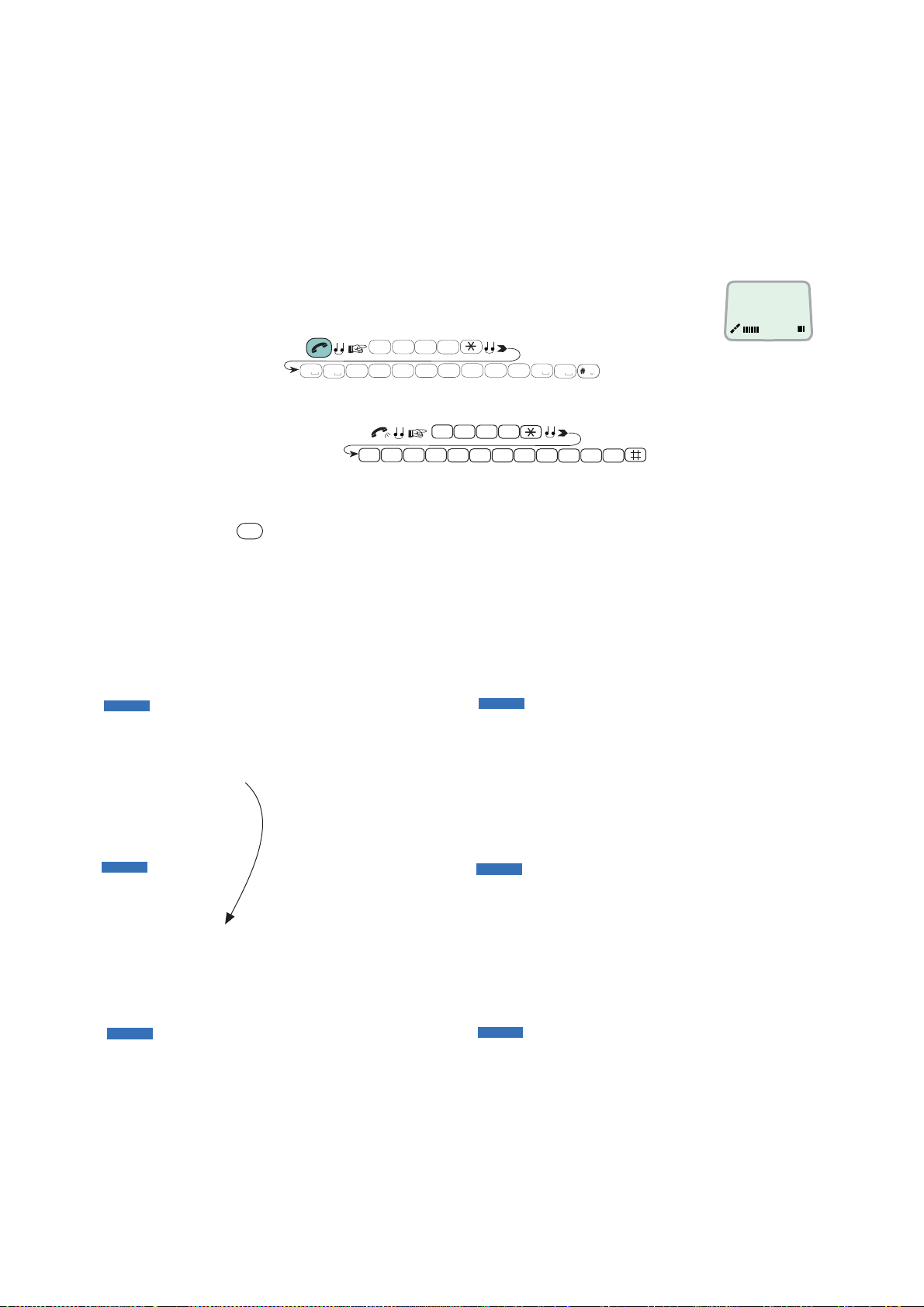
5. CONFIGURATION FROM PC
5.7.3 Access code (owner level only)
Access code can be activated for 4.8 kbps/ 64 kbps speech only.
When the acce s s code function h as been activat ed, the user is always prom pted
for a 1-8 digit personal code when making a call.
All telephones are activated. To release a telephone for use without access code,
see “5.13 MSN configuration”. Entering the personal code a llows the
subscriber number to be dialed, e.g.:
ISDN Handset :
1
2
abc3def4abc
4
abc4abc
2
0
0
Analogue t elephone:
6
8
1
abc
pqrs
abc
7
mno
pqrs
KDD IOR
Code * Dial #
0
7
pqrs
0
A a
SBS
0
0 8 1
1
6
2 3
7 2 4
4
4
7 0 0
Setup:
1 Double-click the Access co de icon in the A ccess control menu and press
Setup
the
button.
2 Pressing New opens t he Access code add entry window, allowing a name
associated with the particul ar c ode to be entered.
3 Pressing Ok allows entering the personal code. Pres sing Ok again prompts
you to conf irm the entry.
4 When pressi ng the Access code icon the next time (1), the window dis plays
a list of the names associat ed with the progr ammed access codes.
COM1 43C 33C
SBS
COM1 43C 33C
SBS
SBS
5-14
COM1 43C 33C
COM1 43C 33C
SBS
SBS
COM1 43C 33C
COM1 43C 33C
Page 67
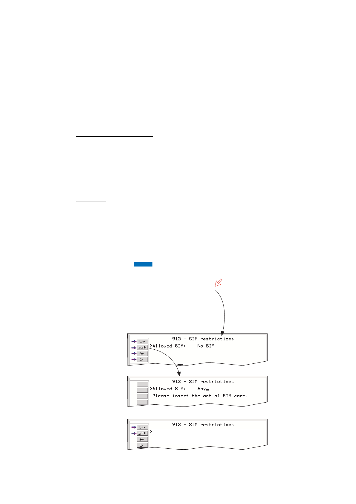
5.7.4 Restricted SIM usage
Allowed SIM
FELCOM 50 c an be s et to operate from:
• Lock SIM, locked to one spec ific SIM card. Any other S I M user will be
rejected.
• No SIM card. All SIM users will be rejected.
• Any SIM card.
Setting SIM restrictions
(owner l evel only)
1 Double-click the Restrict SIM usage icon.
2 The SIM restrictions window shows an example with the setti ng Allowed
SIM: No SIM.
Click Any (default) to set FELCOM 50 for operation from a specific card only.
Lock SIM
3 Click Lock and insert the actual SIM card.
FELCOM 50 can now be operated with that specific card only.
4 When retract ing the card, the Id of the SIM provider is display ed.
Ok stores the settings.
:
1
5. CONFIGURATION FROM PC
SBS
COM1 43C 33C
2
3
4
Allowed SIM: Locked to one
Card number: 89001234567867
Please retract the SIM card.
5-15
Page 68

5. CONFIGURATION FROM PC
5.8 Software update preparation
1 Open the Function menu and then Advanced fun ction menu.
2 Double-click the Software update prep icon.
SBS
COM1 43C 33C
3 Press the YES b utton.
SBS
COM1 43C 33C
4 To view update description press the Descr button.
5 Press the OK button.
The update information is printout .
5-16
Page 69
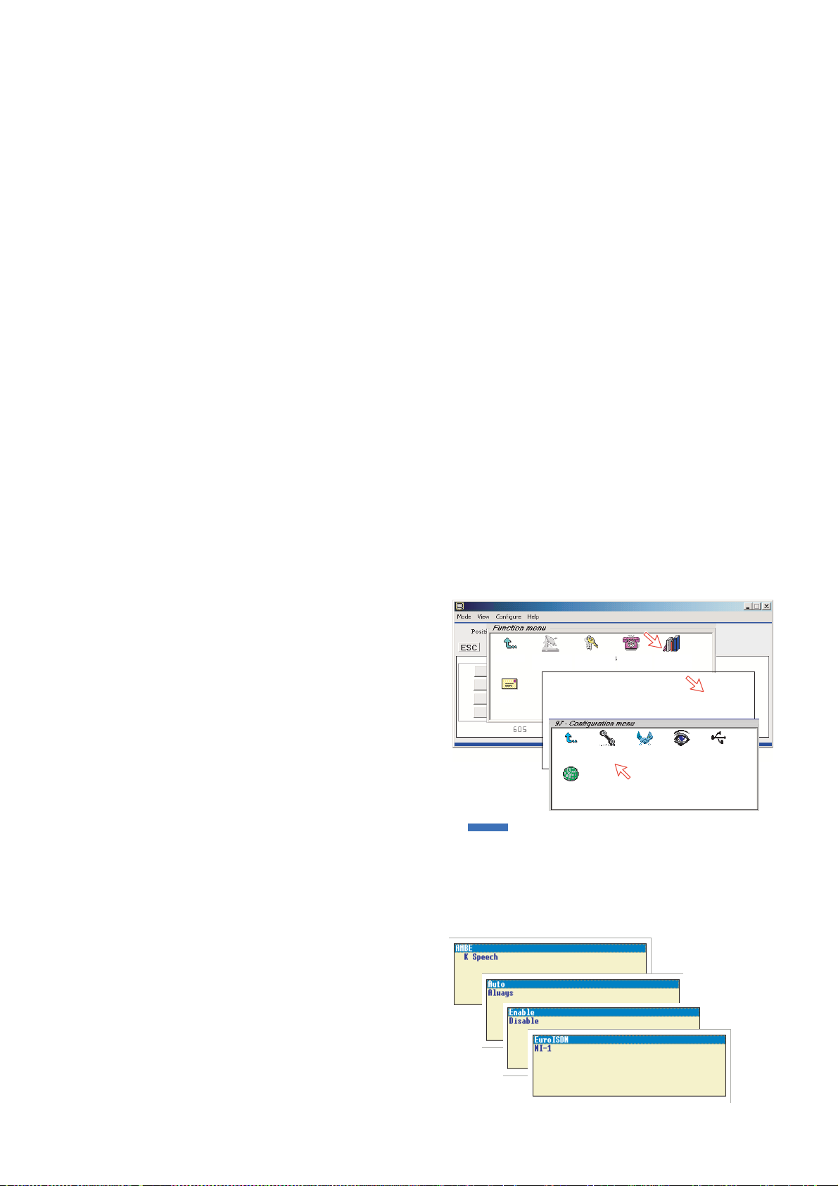
5.9 Configuration menu
5.9.1 ISDN protocol configuration
1 Open the Configuration menu via the Function menu > Advanced
function menu>Configuration.
2 Double-clicking t he ISDN configuration displays the IS DN c onfigurations
implemented in FELCOM 50.
3 Press the up or down arrow key to selec t a it em and the right arrow key to
show t he s election dial og box .
Switch t o owner level to choos e pr otocol.
• Protocol
Select Eur o ISDN for connection of equi pment conforming to the Euro pean
ISDN standard. (NI-1 can not be used.) S elect same protocol for all ISDN
handset s and P C.
• Date/time element
When enabled, date and ti m e is sent to the c onnec ted Terminal Equipment
during call establ ishment. Some ISDN devices do not su rvive thi s m es sage.
The date and t ime transmi s s ion may then be disabled.
• Layer 2 Activation
The lay er 2 c onnection is deactivated aft er s ome idle time as default. Some
ISDN devices interpret this as an alarm situation. Layer 2 deactivation can
then be disabl ed.
• Default service
Some ISDN devices can not
signal t heir own MSN number.
Such a phone will be able to us e
the 64 kbps service since all
“unknown” speech devices ar e
required to use the 4.8 kbps
speech service. The us er c an s et
FELCOM 50 to map all
“unknown” devices to 4.8 k bps
speech service.
Note: Remember to revert to
user level .
1
2
SBS
5. CONFIGURATION FROM PC
1. Set default
Exit Menu
Mail
Net provider
Exit Menu
Exit Menu
Exit Menu
9. Spot Beam
Report Method
2. Set access
level
1. Access
control
1. ISDN
configuration
4. Phone
setup menu
3. Software
updata prep.
2. Net service
providers
9. advanced
functions
4. Alarms
and messages
diagnostics
4. Set
7.
Configuration
6. USB
4.8
5-17
Page 70
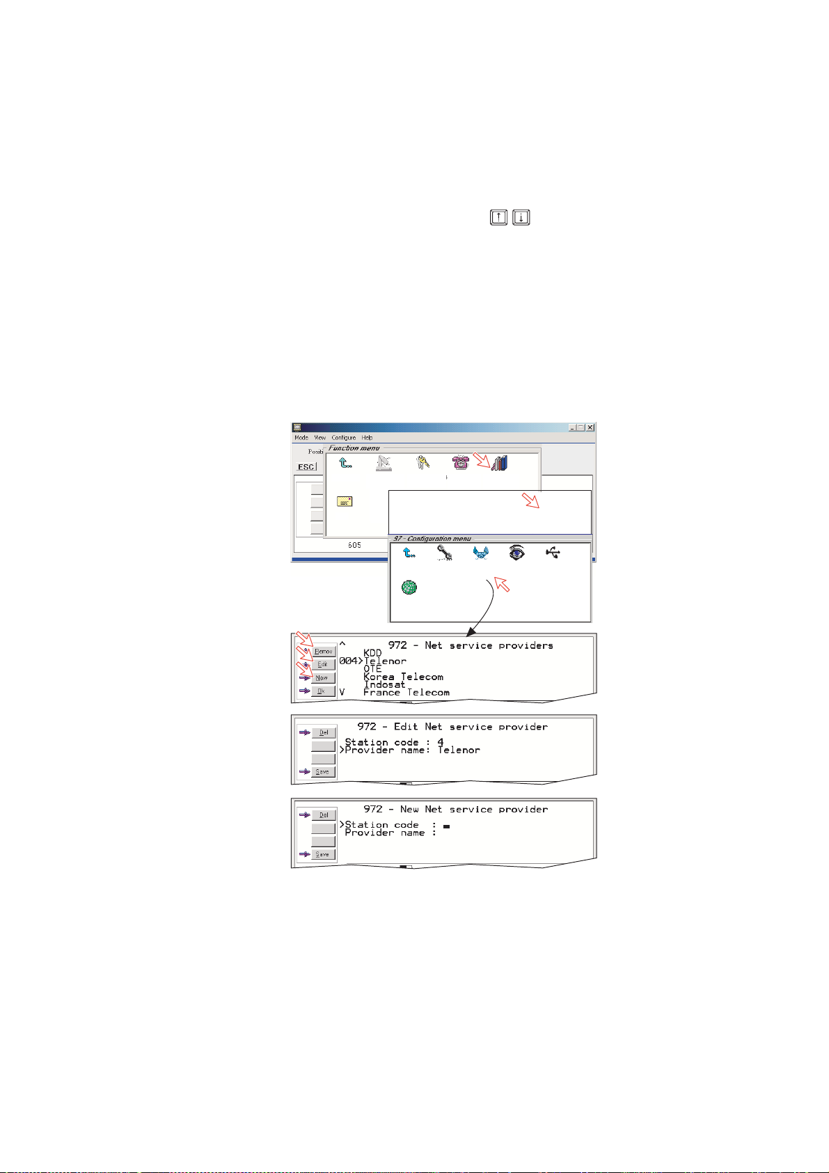
5. CONFIGURATION FROM PC
5.9.2 Net service pro viders (owner leve l onl y)
Adding, edi ting, or removing entri es in the list of Net serv ice providers.
1 Via the Function menu > Advanced functions menu, double-clicking the
Net service providers i c on in the Configuration menu displays the list of
Net servic e providers including t heir stat ion codes.
2 Scroll to required Net s er vic e pr ovider with
you to the Configuration window.
Remov deletes entry.
3. Clicking Edit opens the window al lowing the station code and provider name
to be modified.
Use Del to modify. Save stor es t he c hanges.
4 Clicking New (window 2) opens the window allowing station c ode and
provider name to be added.
Note: Remember to revert to user level.
1
/
Clicking Ok returns
key.
2
4
3
Exit Menu
Mail
1. Set default
Net provider
Exit Menu
Exit Menu
Exit Menu
9. Spot Beam
Report Method
2. Set access
Exit Menu
level
1. Access
1. Access
control
1. ISDN
configuration
4. Phone
setup menu
control
9. advanced
4. Alarms and
3. Software
updata prep.
messages
2. Net service
providers
functions
4. Alarms
6. Satellite
and messages
4. Set
diagnostics
Configuration
setup
7.
6. USB
5-18
Page 71
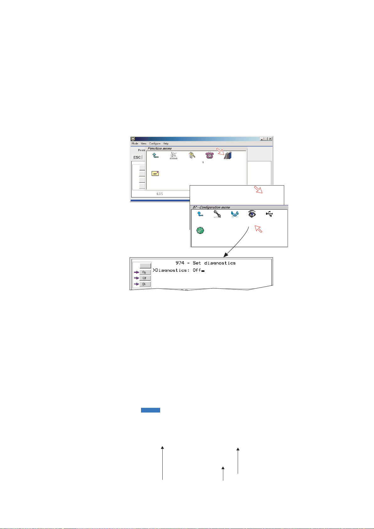
5.9.3 Set diagnostics
Additi onal system i nformation is di s played when diagnostics is turned On.
See also “5.1 Menu functions”.
1 Double-click the Set diagnostics icon via the Function menu > Advanced
functions menu > Configuration menu.
2 Click On or Off as required.
1
5. CONFIGURATION FROM PC
Exit Menu
Mail
1. Set default
Net provider
2. Set access
level
Exit Menu
Exit Menu
Exit Menu
9. Spot Beam
Report Method
4. Phone
setup menu
1. Access
control
1. ISDN
configuration
9. Advanced
functions
3. Software
updata prep.
2. Net service
2
When choosing On, the foll owing terms appear.
• Alarm and message icon ( m enu 9)
• Transcei ver status icon (menu 9-3)
providers
4. Alarms
and messages
4. Set
diagnostics
7.
Configuration
6. USB
• EIRP table icon (menu 9-4)
• Power supply unit temperature
• Calculated spot beam
• Antenna elevation
When pointing at the tim e indication, a popup window shows the year and date.
Calculated spot beam
Power supply temparature
Antenna elevation
5-19
Page 72

5. CONFIGURATION FROM PC
5.9.4 Dual-port USB
The Dual- por t USB allows several program s t o operate at the same time via a
single USB por t. Connect a USB cable between the USB port of the
communication unit and the USB port of P C.
• One channel for dat a c om m unication
• One channel for control (vtLite)
The default setting i s “ Single port”.
To set the dual por t, do as follows.
1 Double-click the USB icon via the Function menu > Advanced functions
menu > Configuration menu.
2 Click the Edit button. Three selections are provi ded.
• Single port: T his unit will appear t o the host PC as a single port CDC
compliant standard USB Modem.
• Dual port WDM: This unit will appear to the host computer with a profile
matching t he Windows dual port device dri ver.
• Dual port (composite): Not in use.
3 Choose Dual port WDM and click the Selct button.
5-20
Page 73

5. CONFIGURATION FROM PC
4 Clicking Save opens Welcome to the Found New Hardware Wizard which
allow s the selection of new USB drivers requi r ed to achieve parallel
operati on vi a the USB port.
5 The Welcome to the Found New Hardware Wizard installs the Nera dual
port modem dri ver required for Du al Port operation.
Click Next and then Finish to complete the installation.
6 The Welcome to the Found New Hardware Wizard now automatic ally
reopens for instal lation of the Nera control driver.
Click Next and then Finish to complete the installation.
7 Open the Control Panel and double-click the Phone and Modem Options
icon verify com ports used on the PC.
5-21
Page 74

5. CONFIGURATION FROM PC
8 Clicking the Modem tab show s the new driver i ns tallations (examples) :
COM6 to be us ed for vtLite M obile
COM3 to be used for dial-ups
Standard 33600 bps Modem
Nera control Port
COM1
COM6
9 Open vtLite Mobile and click Port. Sel ec t the Port COM setting for the new
driver, i.e. 6.
Click Save Sett ings.
5-22
10 Click Mode > Terminal MMI to reestablish vtLite Mobile. You can now
perform data communic at ion at the same time, see the applicat ion:
Mobil e P acket Dat a S ervice via USB, or Mobile Data Service via USB
Page 75
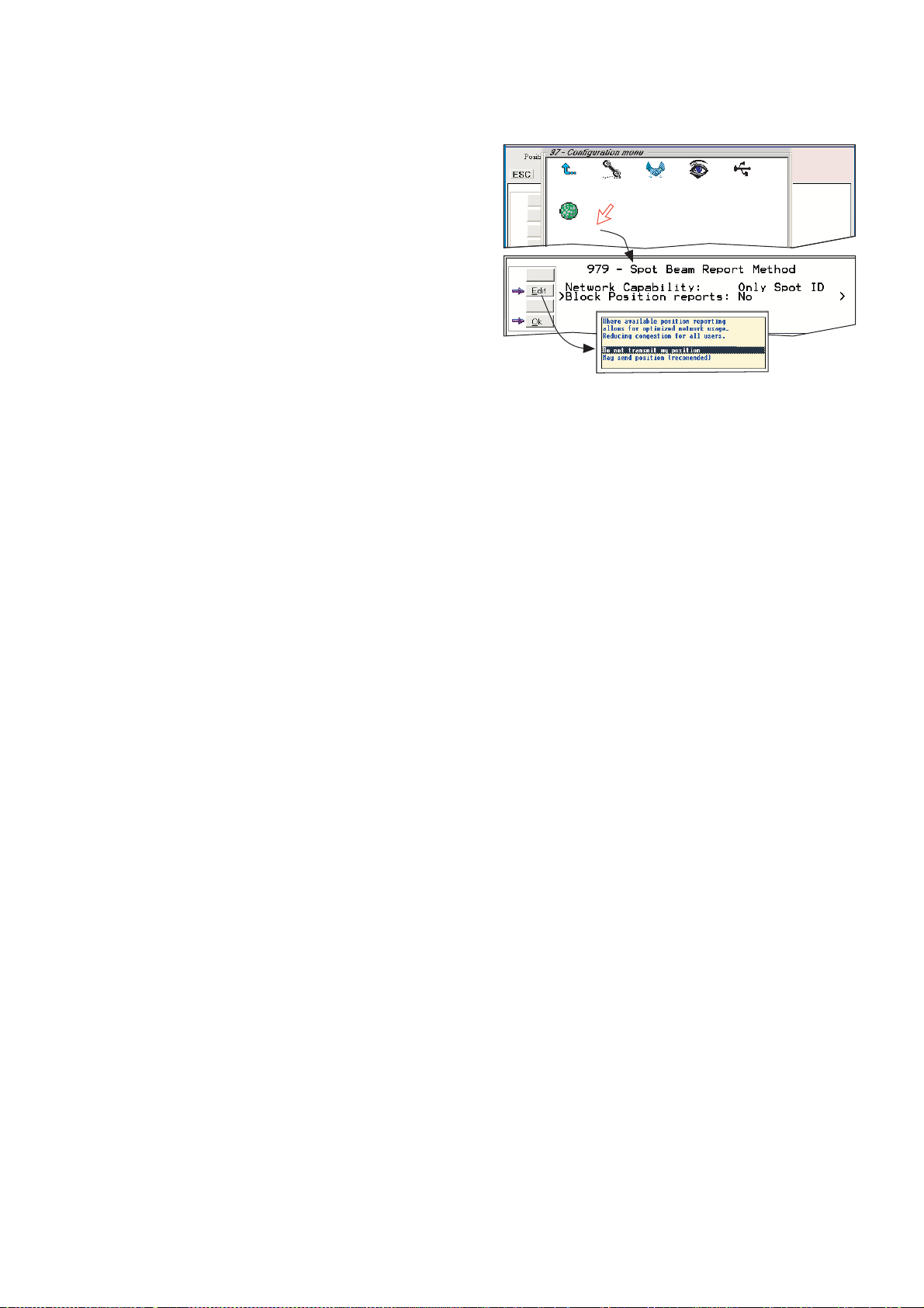
5.9.5 Spot beam report method
1 Double-click the Spot beam
report method icon via the
Function menu > Advanced
functions menu >
Configuration menu.
2 Two selections are provided:
• Do not transmit my position
• May send position (default)
May be change d in owner level
only
5. CONFIGURATION FROM PC
1
9. Spot Beam
Report Method
Exit Menu
1. ISDN
configuration
2. Net service
providers
4. Set
diagnostics
6. USB
2
5-23
Page 76
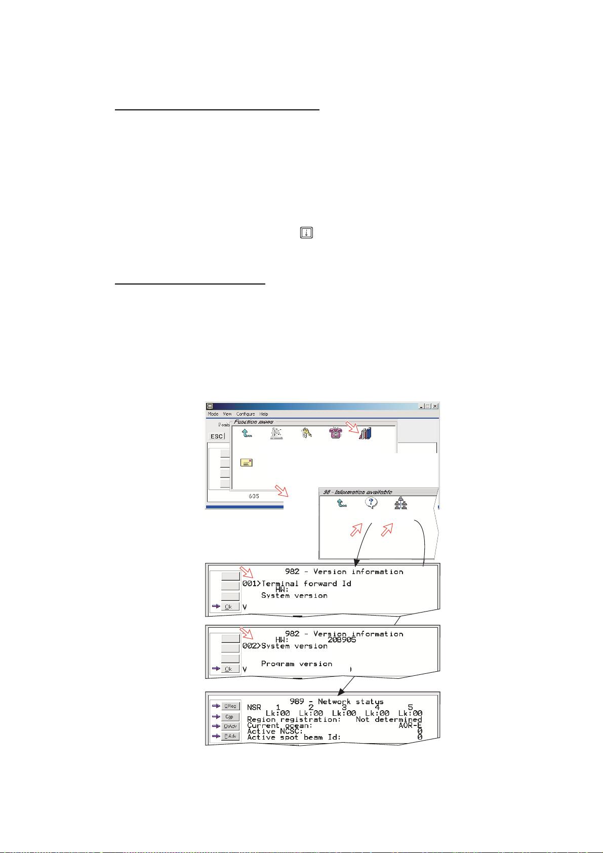
5. CONFIGURATION FROM PC
2. Misc.
version I...
9.Network
status inf...
Exit Menu
5.10 Information available
Miscellaneous version Id information
The Information available function displays the t er m inal forw ar d Id and system
versions.
1 Open the Function menu > Advanced functions menu > Information
available menu.
2 Double-clicking the miscellaneous version Id information icon displays the
available data.
3 With Diagnostics On, pressing
windows.
Network status information
(owner l evel only)
This func tion displ ay s vari ous network status information.
4 Double-click the Network status i nformation icon in the Information
available menu for readout.
NOTE: Remember to revert to user level.
1
opens a series of version information
2
3
4
SBS
Exit Menu
Mail
1. Set default
2. Set access
Net provider
level
Exit Menu
REL 2.0
22 Sep 2003
REL 2.0
22 Sep 2003
PN:101476 Ver.2.0
4. Phone
setup menu
1. Access
control
&
(
3F9BEC
9. Advanced
functions
3. Software
updata prep.
4. Alarms
and messages
7.
Configuration
&'
&'
5-24
Page 77
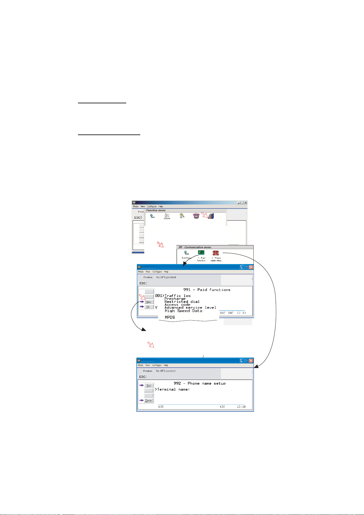
5. CONFIGURATION FROM PC
5.11 Customization menu (owner level only)
1 Open the Customization menu via the Function menu > Advanced
functions menu.
Paid functions
This func t ion is not s upported by the FE LCO M 50.
Phone name setup
2 Double-clicking the Phone name setup icon in the Customization menu
displays the Phone name, i.e. FURUNO F 55. To change, k ey in
uppercase/lowercas e letters as required. Use Del to modify. Save stores the
changes. This name app ear s at some screen.
NOTE: Remember to revert to user level.
2
3
1
Exit Menu
Exit Menu
1. Set default
Net provider
1. Access
control
2. Set access
level
3. Software
updata prep.
4. Phone
setup menu
4. Alarms
and messages
9. Advanced
functions
Configuration
7.
FELCOM 70
FURUNO F55
5-25
Page 78

5. CONFIGURATION FROM PC
5.12 Routing of incoming calls
When apply ing for IMN numbers , a Te rminal Id (OID/DID) is received from the
Net servic e provider. All devices connected to FELCOM 50 can make outgoing
calls. For incoming calls it must be ass ur ed that the Terminal Ids and M S N
numbers conf igured are as commissioned.
To make an incoming call reach a particular device, an MS N num ber and the
Terminal Id "connected" to the IMN number must be programmed into the
Communic ation Unit (CU) . See later i n this manual.
The table below lists valid MSN numbers for t he av ailable ISDN ser vices.
Numbers to be pr ogramm ed:
In ISDN device: In Communication Unit:
MSN number MSN number and Terminal Id
(the Terminal Id is paired with a specific IMN number)
For an easy s tart, the some Terminal Ids and MSN numbers have been
preprogrammed into the CU (m arked with a star in the table).
In the 4.8 kbps speech , 3.1 kHz audio and 9.6 fax columns of the ISDN
PORTS table the Term.Id is repr es ented by an X, allowing an ISDN Term.Id to
be used for analogue ports .
Note: A Term.Id alr eady entered is not accepted.
LIST OF VALID TERMINAL IDs AND MSN NUMBERS
VIA 2-line TA ISDN PORTS ISDN/RS-232/USB PORTS
4.8 sp ee ch 4.8 kbp s speech 64 kbps sp ee ch 3.1 kHz aud io 9.6 fa x 56 kbps d ata 64 kbps d ata
Term. ld MS N
02* 21*
9.6 kbps fax (G3)
Term. ld MS N
11* 40*
11/40: -fax on
TA
Term. ld MS N
01* 20*
0X 21
0X 22
0X 23
0X 24
0X 25
0X 26
0X 27
0X 28
Term. ld MS N
91* 30*
92 31
93 32
94 33
95 34
96 35
97 36
98 37
99 38
Term. ld MS N
6X 4X
62* 42*
6X 4X
6X 4X
6X 4X
3.1 kHz/
64 kbps
audio service
Term. ld MS N
1X 4X
12* 41*
1X 4X
1X 4X
1X 4X
Term. ld MS N
71* 50*
72 51
73 52
74 53
75 54
76 55
77 56
78 57
79 58
Term. ld MSN
51* 60*
52* 61*
53* 62*
54* 63*
55 64
56 65
57 66
58 67
59 68
51/60, preset for ISDN port
52/61, preset for RS-232A port
53/62, preset for RS-232B port
54/63, preset for USB port
5-26
Page 79
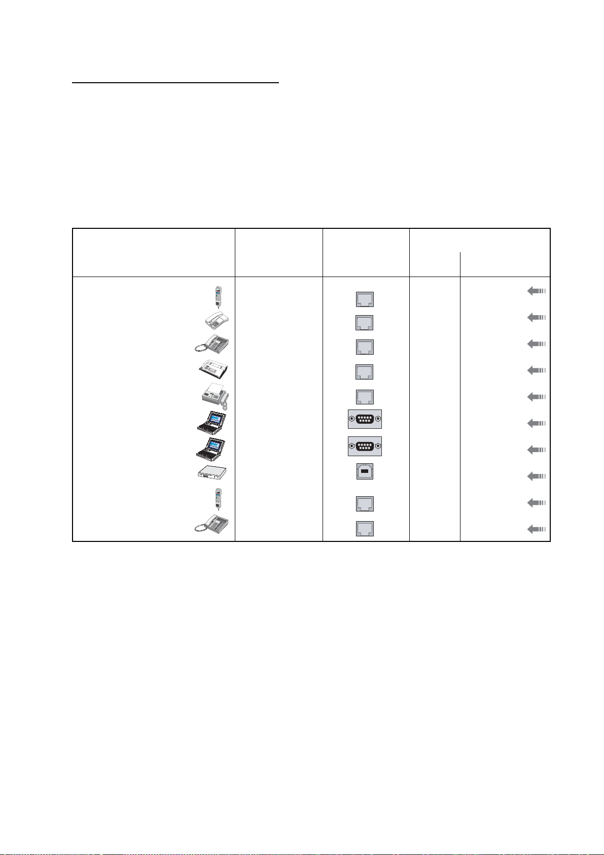
Routin g of incoming cal ls (examples)
The table below illus trates the use of appr opriate Terminal Ids for the various
services com bined wit h ex amples incoming IMN numbers.
* Preprogrammed, see table on previous page.
Note: If the Net ser vi ce pr ovider does not specify which Terminal I d shoul d be
used wit h the various IMN num ber s , select Term. Id no.1 for the first 4.8
kbps telephone, then no. 2 for the second phone. Use the s am e pr inciple
for the other type services. It is advis able to note down the selections.
Name Service MCU ports
(
+
,
+
,
.
,
/
-
-
-
Bridge
Saloon
Radio room
Nera TA
Fax Gr .4
MSN20*
MSN21*
MSN22
MSN40*
MSN60*
4.8 kbps speech
#
$
(
%
&
'
(
!
"
)
*
+
,
.
4.8 speech
/
%
$
#
)
0
4.8 kbps speech
9.6 kbps fax
64 kbps data
5. CONFIGURATION FROM PC
Provided by ISP:
Term.ld IMN
ISDN
TA-TEL1
ISDN
01*
02*
03
TA-TEL2
11*
ISDN
51*
762420510
76242051 1
762420512
762420513
600020521
Data
Data
Router
Bridge
Captain
MSN61*
MSN62*
MSN63*
MSN30*
MSN31
64 kbps data
64 kbps data
64 kbps data
(
+
,
+
,
.
,
/
-
-
-
#
$
(
%
&
'
(
!"
)
*
+
,
64 kbps speech
64 kbps speech
RS-232A
RS-232 B
USB
ISDN
ISDN
52*
53*
54*
91*
92
600020522
600020523
600020524
600020525
600020526
5-27
Page 80

5. CONFIGURATION FROM PC
5.13 MSN configuration
You are prompted t o enter the ow ner level password (default : 1234567890). For
security, the pas s word should be chan ged before or after configuration of a
device. See “ Changing owner level password” on p age 5-5.
Click to open Device Manager for configurat ion of ISDN/RS-232/ RS -4 22/USB.
5-28
Page 81
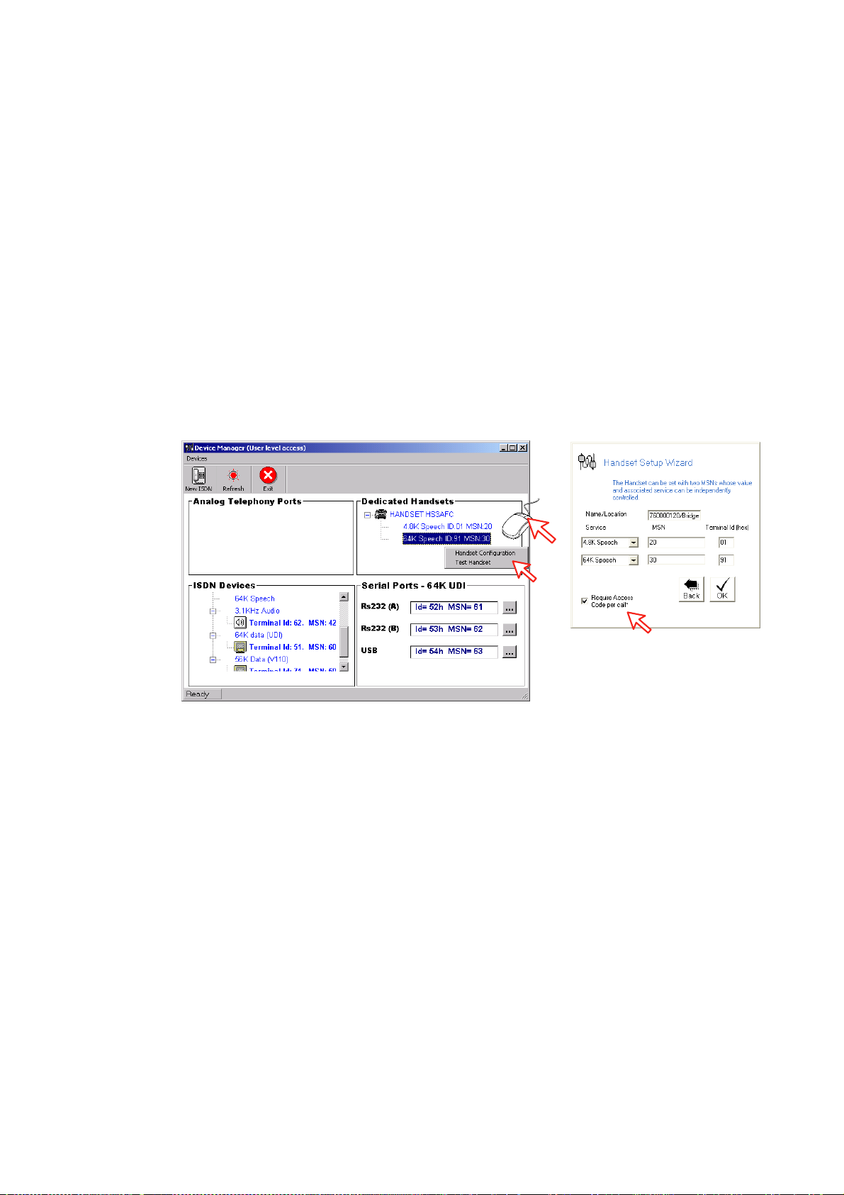
5.13.1 ISDN Handset
• ISDN Handsets will automatic ally be configured with Handset MSNs in the
Device M anager.
• The first ISDN Handset c onnected will be given MSN20 and MSN22.
• The next ISDN Handset will be the next available MSNs.
• The MSNs can be controlled independ ently, e.g. if two handsets are given the
same MSN, they will both r es pond to an incoming call t o that MSN.
• To verify selected MSNs of a handset, check in the Devi c e Manager or press
the "R"-butt on on the Handset.
To open device manager, see previous page.
Right- clicking a Dedicated Handset and then click ing Handset Configuration
starts the Handset Setup Wizard. Enter Name/Location of the installed Handset,
as equipment
5. CONFIGURATION FROM PC
Require Access Code
must be unchec k ed to
allow this Handset to be
used wit hout entering a cod e.
5-29
Page 82
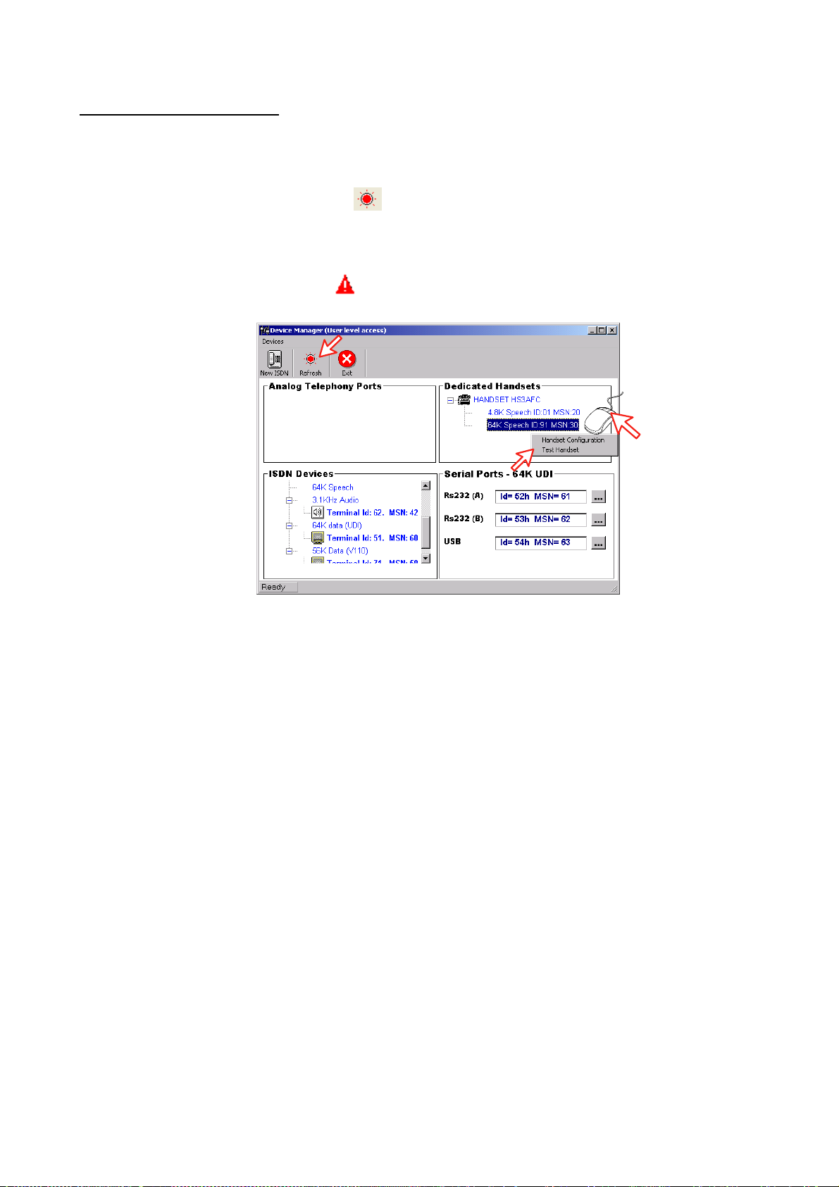
5. CONFIGURATION FROM PC
Deleting an ISDN Handset
Unplug the ISDN Handset to be deleted and rightcl ick the same in the
Dedicated Handset list. Clicking Test Handset remo ves i ts data, leaving the
Terminal Id and MSN number vacant for another Display Handset.
If necessary, click refresh:
Communic ation Unit will remember the handset connection data. All handsets
are given a unique name.
Note: A t r iangle symbol
Handset i s m issing.
and repeat clicking Test Handset. The
in the Device Manager appears when a Display
5-30
Page 83
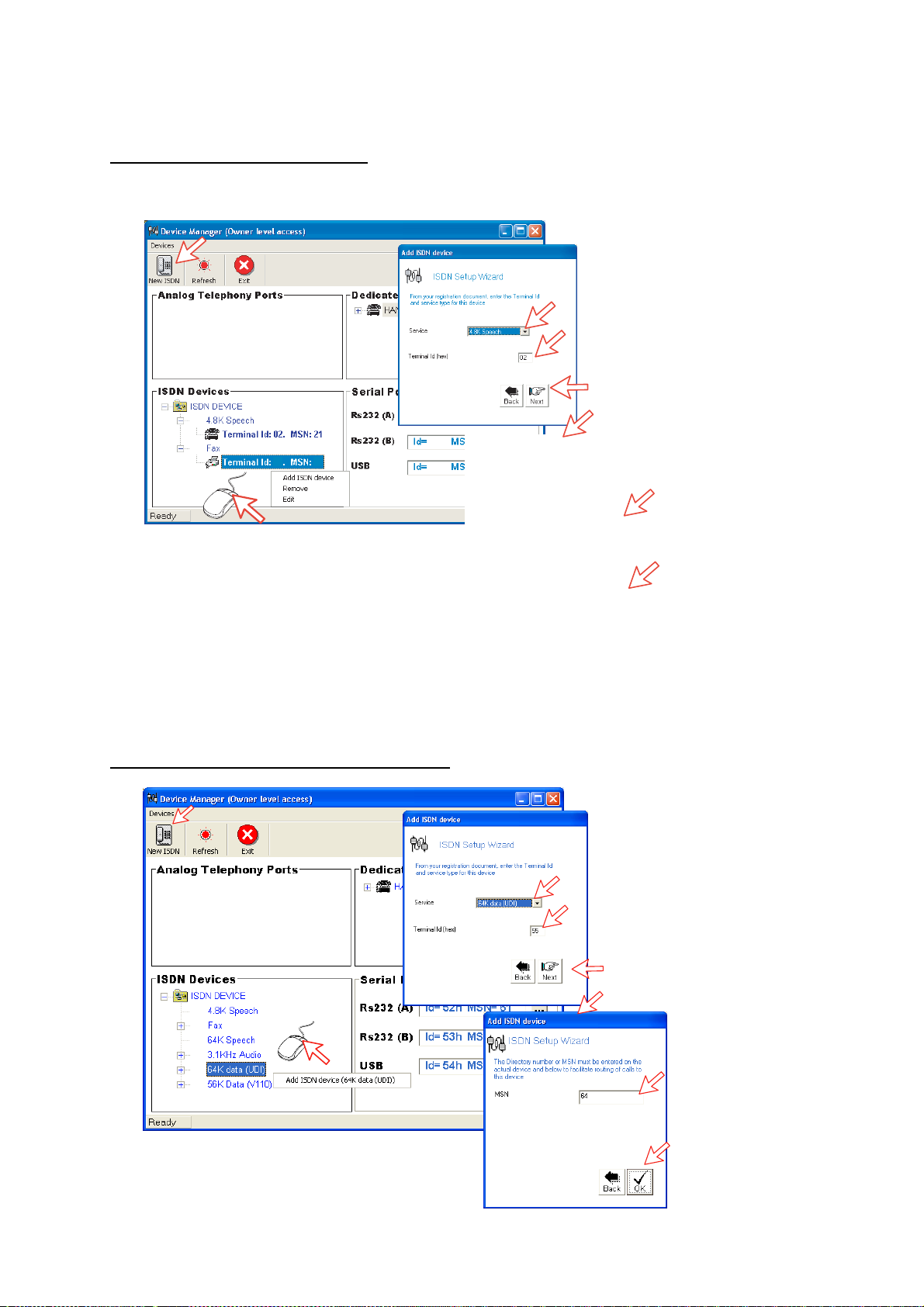
5.13.2 ISDN port
A
Selection example: 4.8k speech
Open device manager and click the New ISDN button to open ISDN Setup
Wizard.
52h
41
12
Echo Cancellation is performed
automatically f or all v oic e c alls .
Uncheck if problems with echo
cancellation.
Require Access Code is checked
when used for 4.8 speech and 64
kbps speech.
pply charge tone is used when
connecting pay phone.
Selection example: 64 kbps data service
54h
5. CONFIGURATION FROM PC
Select the required service:
• 4.8 kbps standard speech service
• 64 kbps speech service
• 3.1 kHz Audio
• 56 kbps data service (V110)
• 64 kbps data service (UDI)
• fax (9.6 kbps fax)
Click to continue.
The system selects the Next
available Terminal Id. Check with
Terminal Id received
from Net provider.
Key in MSN number
if not using the
23
recommended one.
Access Code is not
used for ISDN data.
Click to enter
number.
Select the required service:
4.8 kbps standard speech service
•
64 kbps speech service
•
3.1 kHz Audio
•
56 kbps data service (V110)
•
•
64 kbps data service (UDI)
fax (9.6 kbps fax)
•
Click to continue.
The system selects the Next
available Terminal Id. Check with
Terminal Id received
from Net provider.
Key in MSN number
if not using the
recommended one.
Access Code is not
used for ISDN data.
Click to enter
number.
5-31
Page 84
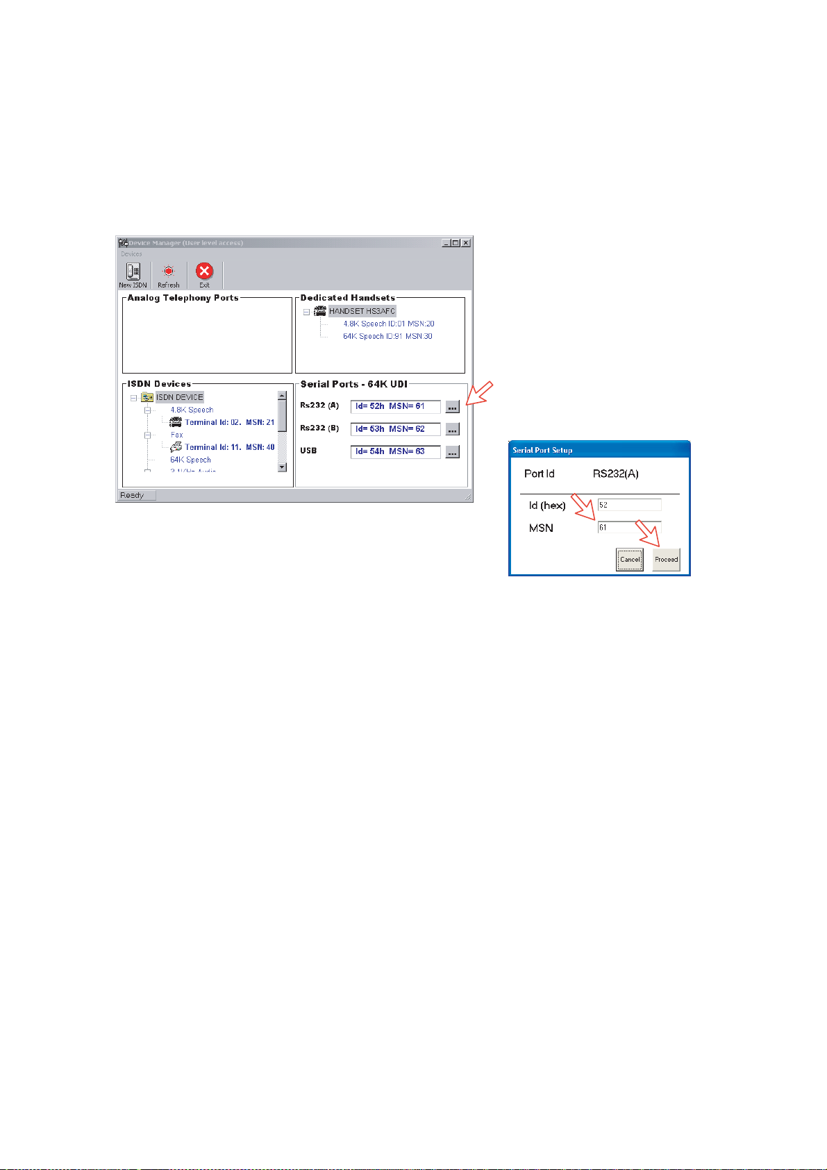
5. CONFIGURATION FROM PC
5.13.3 RS-232 port
Open device manager and click [---] but ton of the RS232 on the Serial Port s64K UDI to open Ser ial Port Setup window.
Key in M S N num ber if not using the recommended one. Click Proceed button to
enter number.
Click to open Serial Port Setup.
Key in MSN number if not using
the recommended one.
Click Proceed to enter number.
5-32
Page 85
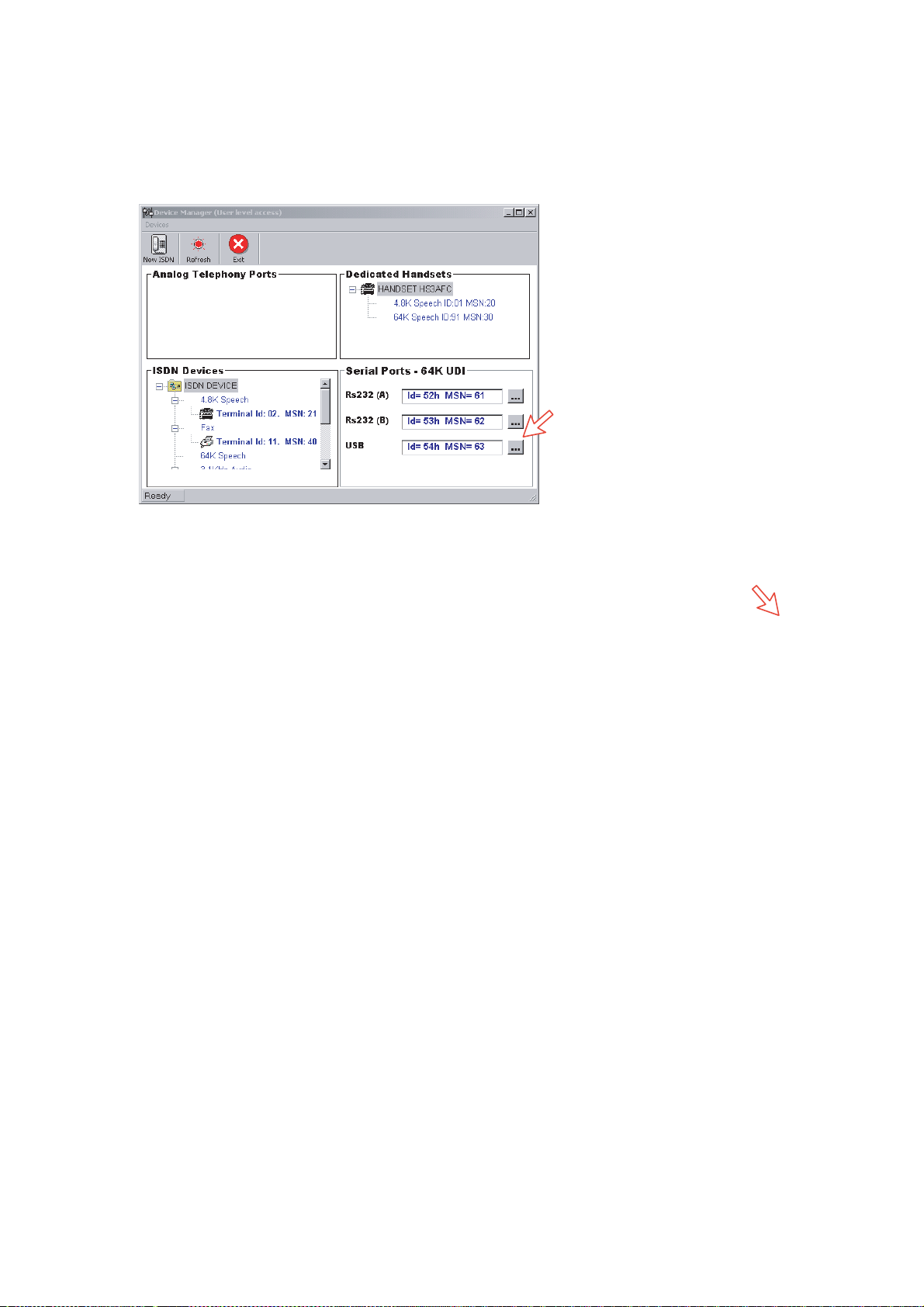
5.13.4 USB port
Open device m anager and click [---] button of the USB on the Serial Ports-64K
UDI.
5. CONFIGURATION FROM PC
Click to open
Serial Port
Setup.
Key in MSN number
if not using the
recommended one.
Click Next to
enter number.
5-33
Page 86
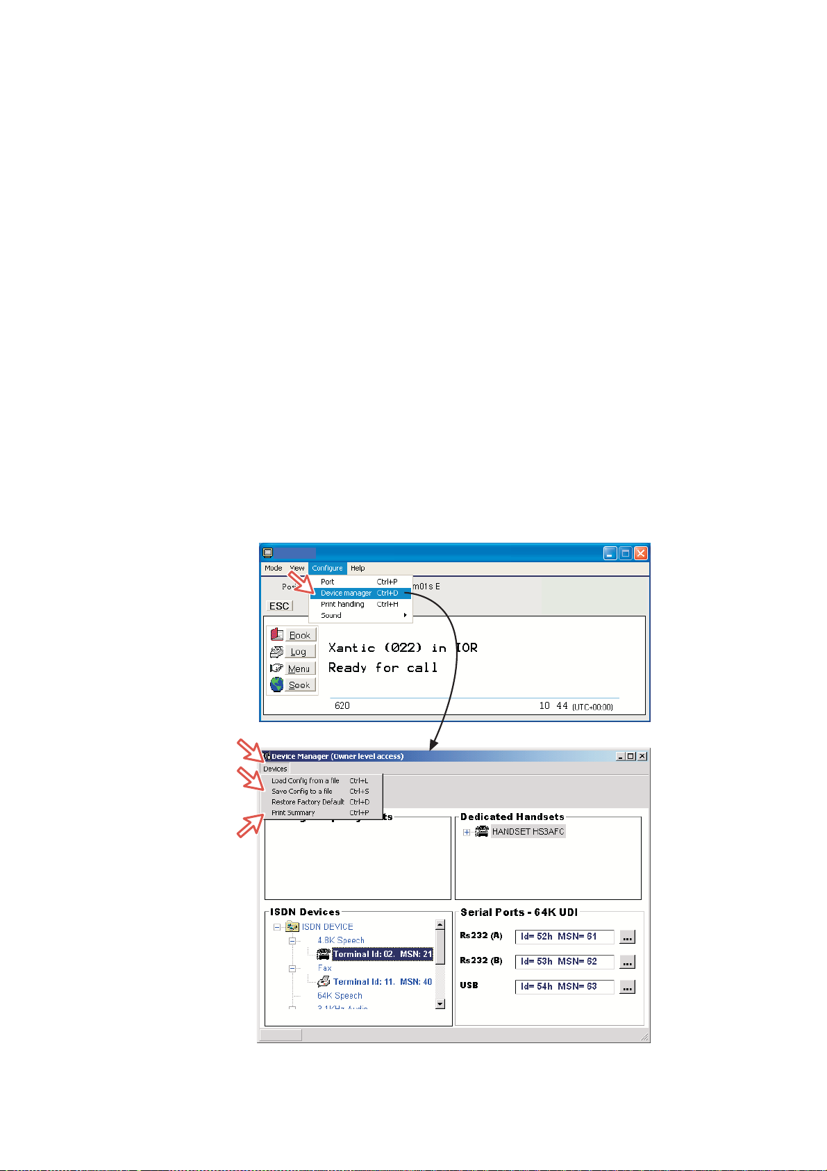
5. CONFIGURATION FROM PC
5.14 Saving and reloading configurations
The FELCOM 50 configurat ion settings m ay be stored on the PC hard disk, e.g.
prior to replacing software.
Procedure
1 Open the Device Manag er window as indicated.
2 Clicking Devices > Save confi g to a file aut om atically stores the dat a in a
“Config. cgf” file in the vtLite directory c:/program files/vtL ite Mobile.
3 After install ing the sof tw ar e, the settings may be transferred back to
FELCOM 50 by pressing Load.
4 Clicking Restore Factory D ef aults loads defaul t FELCOM 50 configurations.
Printout /storing a conf iguration summ ar y:
5 Clicking Print Summary opens t he Printout Viewer (see next page) which
list s the settings of t he end us er equipment, and allows filing and/or printout.
Note: Save config to a file only saves the Device Manager settings. Setting
such as Net pr ovider / Access codes / ISDN pr otocol are not saved.
Phone book data and traffic log must be saved in the Book and Log
menus.
5-34
Page 87
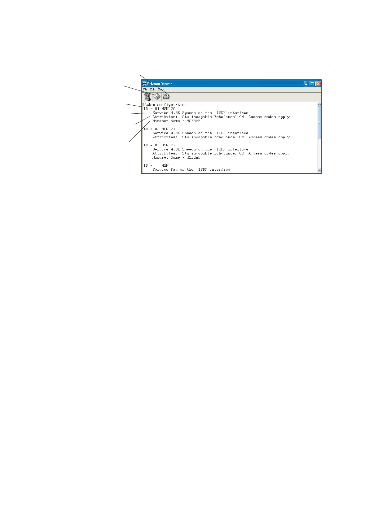
Configuration printout viewer
The lis t is sorted by Terminal Id.
Print to local printer
Save to disk
Terminal ld and
MSN number
Tyep of service
Individual device
settings
Name/location,
if entered
12
5. CONFIGURATION FROM PC
41
5-35
Page 88
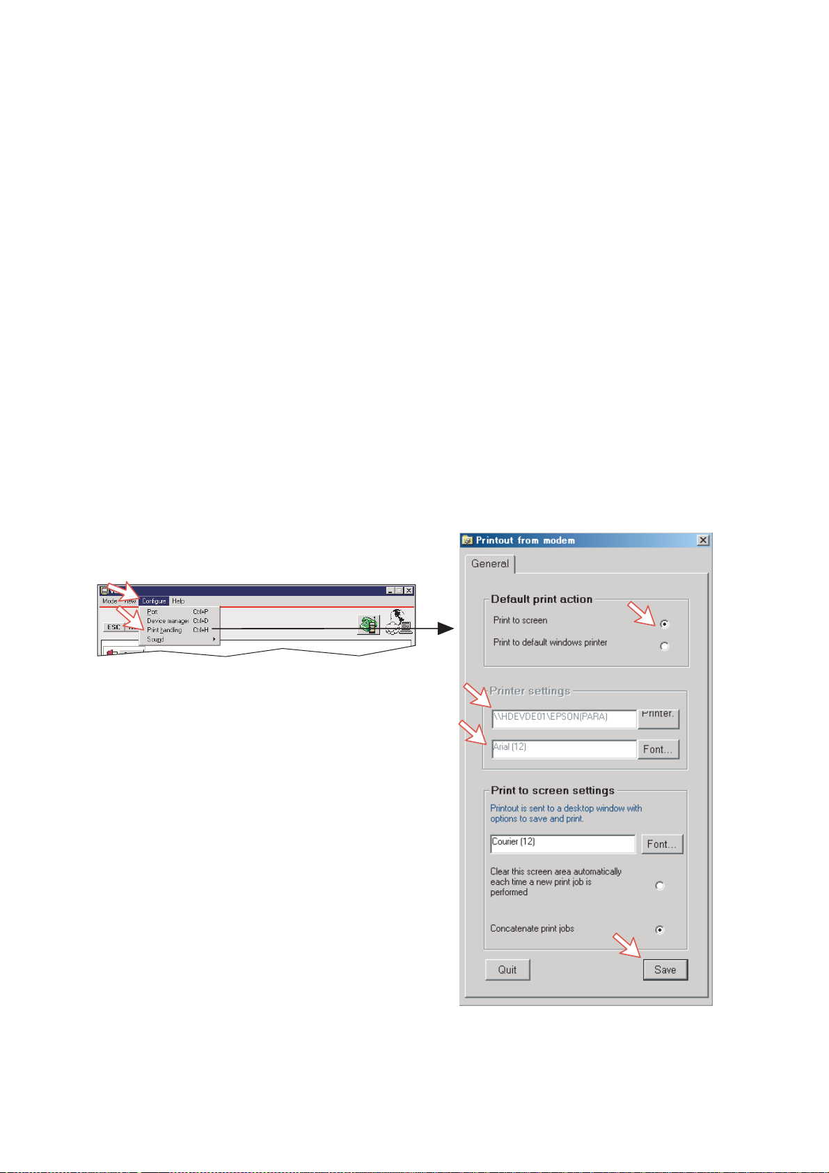
5. CONFIGURATION FROM PC
5.15 Print handling setup
The Printout from modem window is used for setti ng of default output of Traffic
log, M odem c onf iguration, etc.
Clicking Configure > Print handling opens the Printout from modem wind ow.
The following settings are selectable.
Default print action:
Normally, choose Print to screen which causes t he file to be output vi a the
Printout vi ewer. For an example, see “4.6 Traffic Log Printout viewer”.
For direct pr intout, choos e Print to default windows printer.
Print to screen set t ings:
Determines the output of r ec or ds via the Printout viewer. Normally, use
Concatenate print j obs which “chains” the jobs to be printed or saved to file.
The alternative choice c lears the screen after each printout.
Printer settings:
For hardcopy printout, make sure that the appropriat e pr inter and font are
selected.
5-36
Page 89

5.16 Ethernet interface
Port configuration gets an additional tag for Telnet settings. Click Configure >
Port and Telnet settings tag.
5. CONFIGURATION FROM PC
If Enable access vi a LAN is tick ed then vtLite will attempt to c om m unicate
using a raw telnet connection to the ser ver address give n in the server box. It will
use the default telnet por t 23.
If Empty ERB access mode is als o ticked then over the telnet session the vtLite
will att em pt to login to an Et her net Router Board (currently no in use).
If the Et her net c onnec tion is used t hen the vtLite port indicator will show “LA N”
rather than the port number.
5-37
Page 90

5. CONFIGURATION FROM PC
This p age is intentionally left blank.
5-38
Page 91
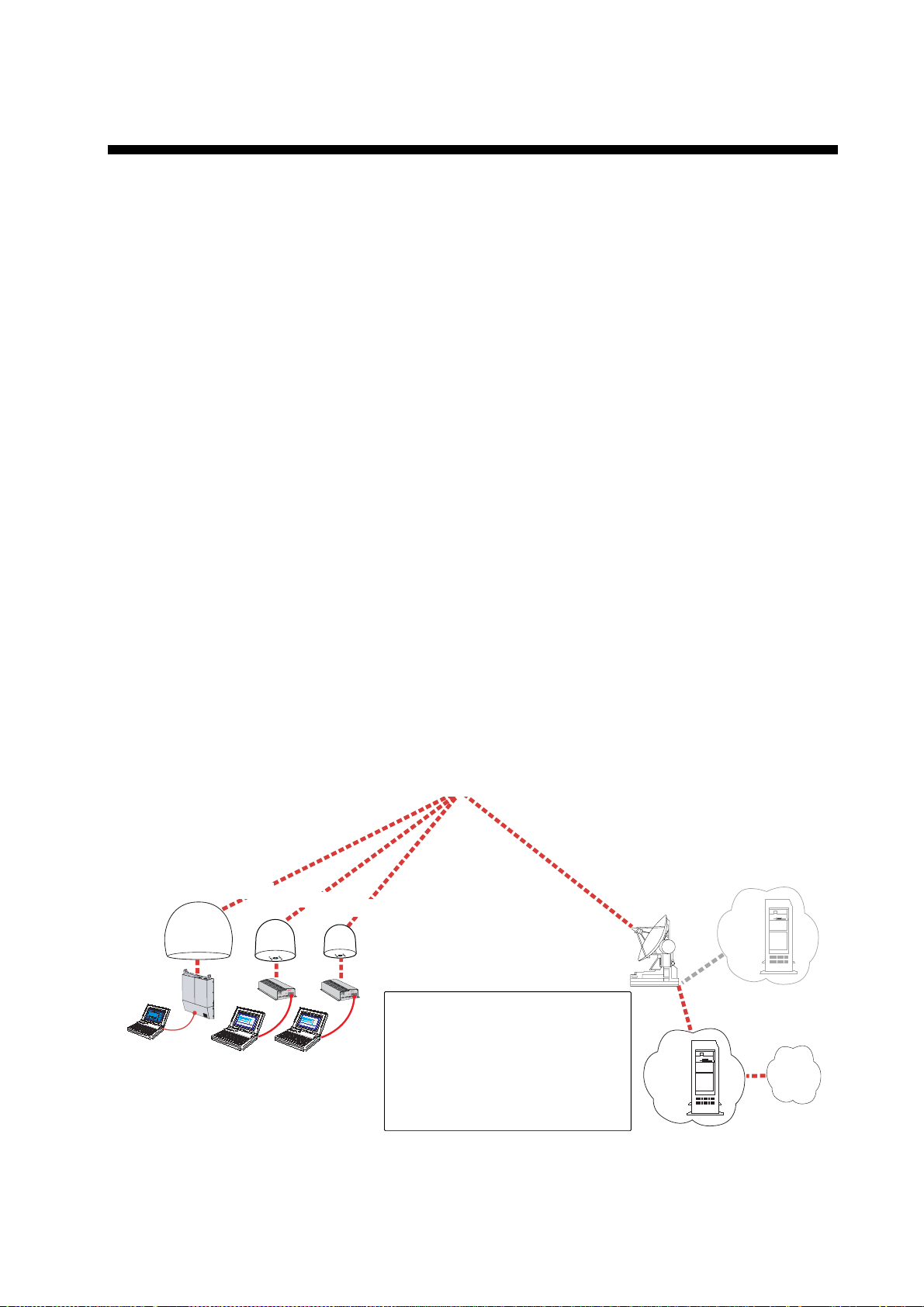
6. DATA COMMUNICATION
6.1 Mobile Packet Data Service (RS-232)
6.1.1 Introduction
The Mob i le Packet Dat a S ervice compl ies wi th the communicati on pr otocol
defined by the Inmarsat system.
The transmission data rate over the satellite link is typically 20 kbps (a 64 kbps
channel is s har ed with other users).
Swit c hing bet ween MPDS and Mobile ISDN service is done f r om the PC.
The PC must have Win 2000 or Wi n X P installed.
With MPDS you only pay for the amount of data received or transmitted, rather
than for the t ime you are connect ed.
MPDS can be efficient for applic ations that involves brief bursts of
communication followed by periods of inactivi ty, such as:
• E-mail
PC w/Windows
2000 or later
• Internet/intranet
• Navigational updat es
• Scada
• Database queries
• E-commerce
• VPN - Virtual P ri vate Network
FELCOM 70
FELCOM 50
FELCOM 30
SBS (Shared Base Station) assigns channels to
the MPDS user and handles the MPDS
communication. Terminals in MPDS mode share
data channels with other users.
RLES (Regional Land Earth Station) sets terminal
in MPDS list. A terminal can not receive a voice
call when in MPDS mode.
Home LES (Home Land Earth Station) gives
access to MPDS service like Internet/e-mail. It
also handles the MPDS biling system.
Land
Earth
Station,
LES
SBS
Home
LES
R
LES
Internet
System Overview
6-1
Page 92
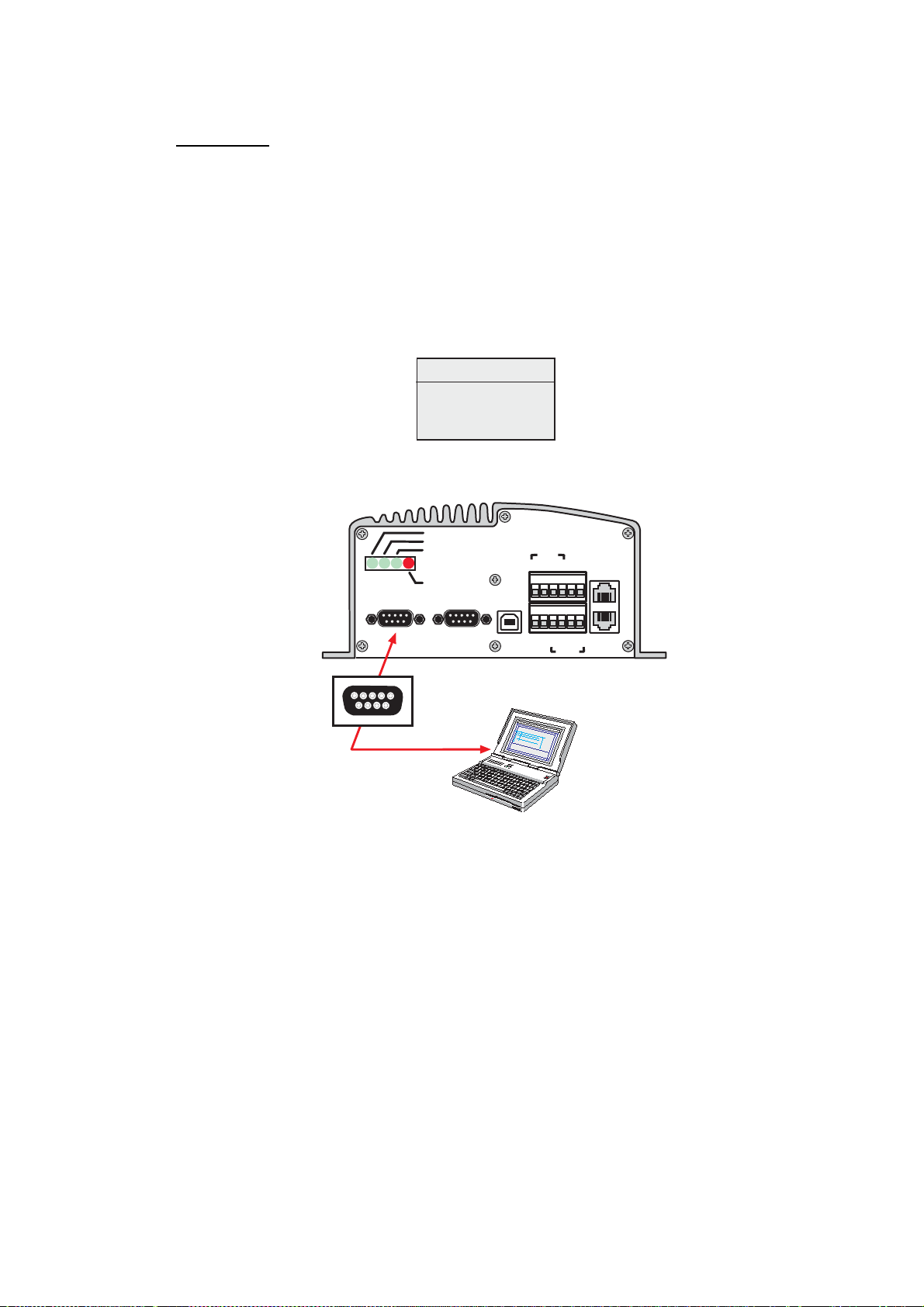
6. DATA COMMUNICATION
6.1.2 Connecting up
Installation
Connect the RS - 232 serial c able between the serial port on the PC and the
RS-232 port on the CU.
The default settings are:
Data sp eed: 115200 bps
Format: 8 data bits, no parity, 1 stop bit
Flow control: Hardware (RTS/CTS)
Modem Drivers
Win 2000/XP:
- Std 33.600 bps
FELCOM 50
ON
48 VDC
4321
5
876
9
RS-232 A
5
321
4
9
876
SYNC
ALARM
RS-232 B
5
321
4
9
876
USB
ISDN
TX+
NMEA-
TX-
NMEA+
RX-
RX+
TX-
TX+
RS-422
ISDN
ISDN
RX+
RX-
PC serial port
DTE
6-2
Page 93

6.1.3 MPDS - setup
(Window s XP is used as an example)
Ensure that vtLite Mobile is closed.
1 Open the Control Panel on the PC and double- c lick the Phone and Modem
Options icon.
6. DATA COMMUNICATION
2 Click the Modems tab.
Click Add, see next page.
6-3
Page 94
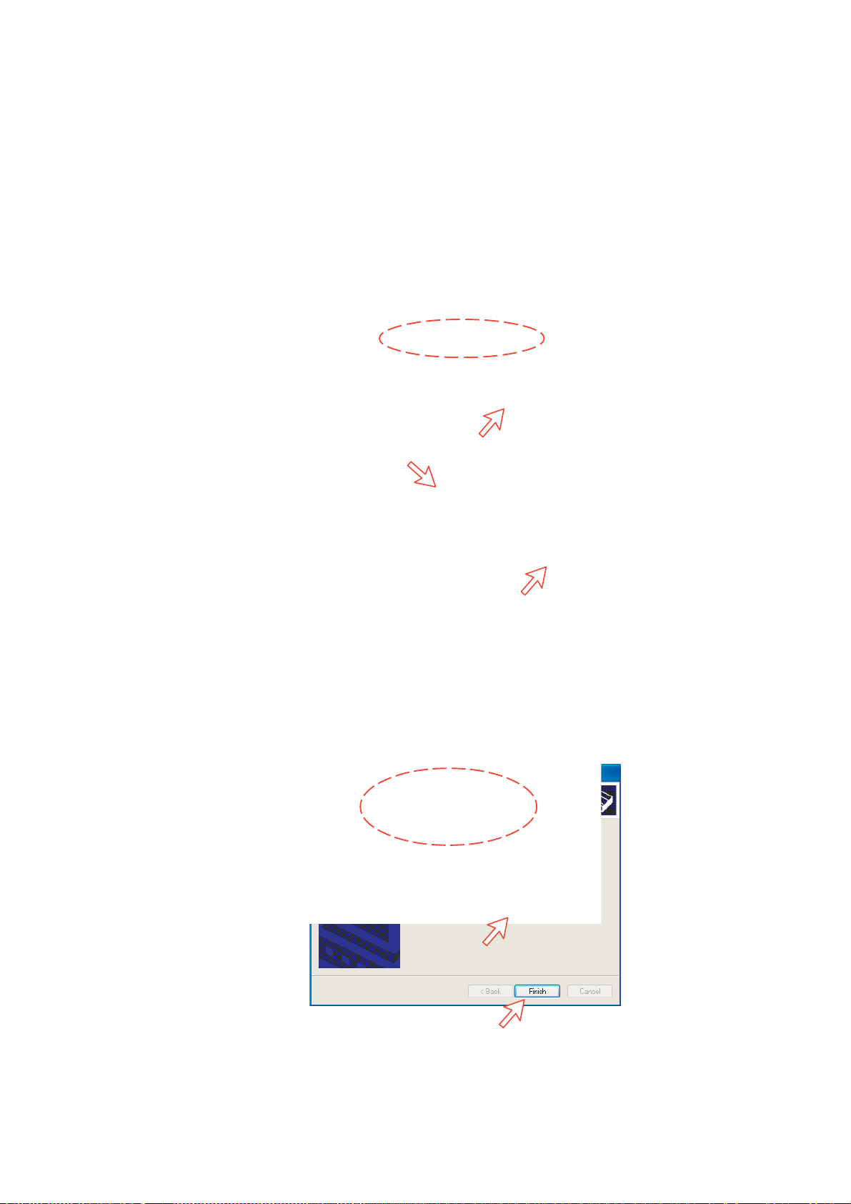
6. DATA COMMUNICATION
3 In the Ad d Hardware Wiz ard window check "Don't detect my modem", and
click Next.
Select Standard 33600 bps Modem in the Models field, and click Next.
4 Select the port to which the Modem driver should be installed.
Click Next and then Finish to complete the installation.
6-4
Page 95

6. DATA COMMUNICATION
5 Opening the Phone and Modem Options window confir m s the establis hed
modem conne c tion.
Select “Standard 33600 bps Modem”.
Note: The setup f or data transfer to the CU is bas ed on the Windows 2000/XP
default parameters:
8 data bits - no parity - 1 stop bit - flow ctrl: H ardware
Clicking Properties allows checking the p ar ameters.
6 Open the Control Panel on the PC and double- c lick the Network
Connections ic on.
6-5
Page 96
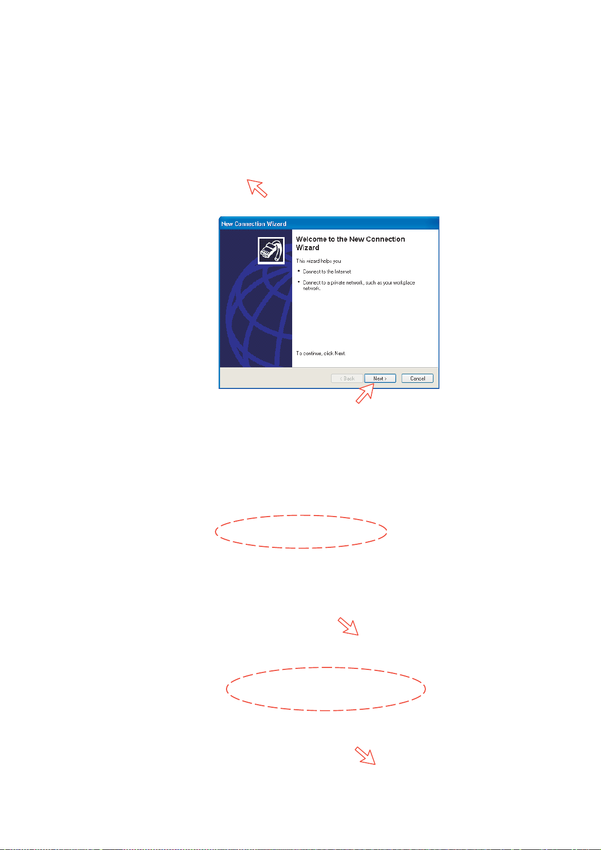
6. DATA COMMUNICATION
7 Click Create a new connectio n to open the New Connection Wizard.
Click Next.
8 Check Connect t o the Intern et . Click Next.
Check Set up my connection manually.
Click Next.
6-6
Page 97

6. DATA COMMUNICATION
9 Check “Connect using a dial-up modem” . Click Next.
10 Check “Modem Standard 33600 bps Modem.” Click Next.
Enter the name for the connection e.g. MPDS. Click Next.
6-7
Page 98
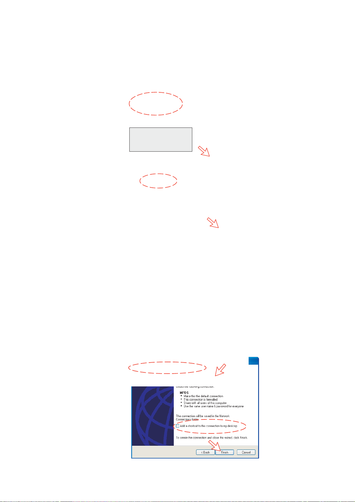
6. DATA COMMUNICATION
11 Entering phone nu m ber **94# automati c ally connects you to the Internet
Service Pr ovider through your default Net Provider. Click Next.
Check Anyone's use, and click Next.
Note: Hash # may be
omitted on some PCs/
Windows versions.
12 Enter name a nd passwor d for the connect ion.
Uncheck Turn on Internet Connection Firewall for this connection. Click
Next.
Complete the New Connection, click Finish.
FURUNO
6-8
Page 99

6.1.4 Checking default settings
1 Double-click Network Connections in the Control Panel.
6. DATA COMMUNICATION
2 Right-click the MPDS dial - up c onnection and click Properties.
6-9
Page 100

6. DATA COMMUNICATION
3 Check settings in the MPDS Properties w indow:
• Modem - Standard 33600 bps Mode m ( COM1)
• Phone number: **94#.
Click Configure.
4 In the Modem Configuration window, check that the Maxi mum speed (bps)
is set to 115200.
6-10
 Loading...