

Page 1

OPERATOR'S MANUAL
FISH SIZE INDICATOR
Model
FCV-2100
(Product Name: FISH FINDER)
www.furuno.com
Page 2
Attach Transducer Data Sheet here.
Pub. No. OME-23910-A1
( ETMI ) FCV-2100
A : ARR. 2016
A1 : JUN. 6, 2016
Page 3
IMPORTANT NOTICES
Ni-Cd Pb
General
• This manual has been authored with simplified grammar, to meet the needs of international users.
• The operator of this equipment must read and follow the descriptions in this manual. Wrong operation or maintenance can cancel the warranty or cause injury.
• Do not copy any part of this manual without written permission from FURUNO.
• If this manual is lost or worn, contact your dealer about replacement.
• The contents of this manual and equipment specifications can change without notice.
• The example screens (or illustrations) shown in this manual can be different from the screens
you see on your display. The screens you see depend on your system configuration and equipment settings.
• Save this manual for future reference.
• Any modification of the equipment (including software) by persons not authorized by FURUNOwill cancel the warranty.
• All brand and product names are trademarks, registered trademarks or service marks of theirrespective holders.
How to discard this product
Discard this product according to local regulations for the disposal of industrial waste. For disposal
in the USA, see the homepage of the Electronics Industries Alliance (http://www.eiae.org/) for the
correct method of disposal.
How to discard a used battery
Some FURUNO products have a battery(ies). To see if your product has a battery, see the chapter
on Maintenance. Follow the instructions below if a battery is used. Tape the + and - terminals of
battery before disposal to prevent fire, heat generation caused by short circuit.
In the European Union
The crossed-out trash can symbol indicates that all types of batteries
must not be discarded in standard trash, or at a trash site. Take the
used batteries to a battery collection site according to your national
legislation and the Batteries Directive 2006/66/EU.
In the USA
The Mobius loop symbol (three chasing arrows) indicates that Ni-Cd
and lead-acid rechargeable batteries must be recycled. Take the used
batteries to a battery collection site according to local laws.
Cd
In other countries
There are no international standards for the battery recycle symbol.
The number of symbols can increase when the other countries make their own recycle symbols
in the future.
i
Page 4
SAFETY INSTRUCTIONS
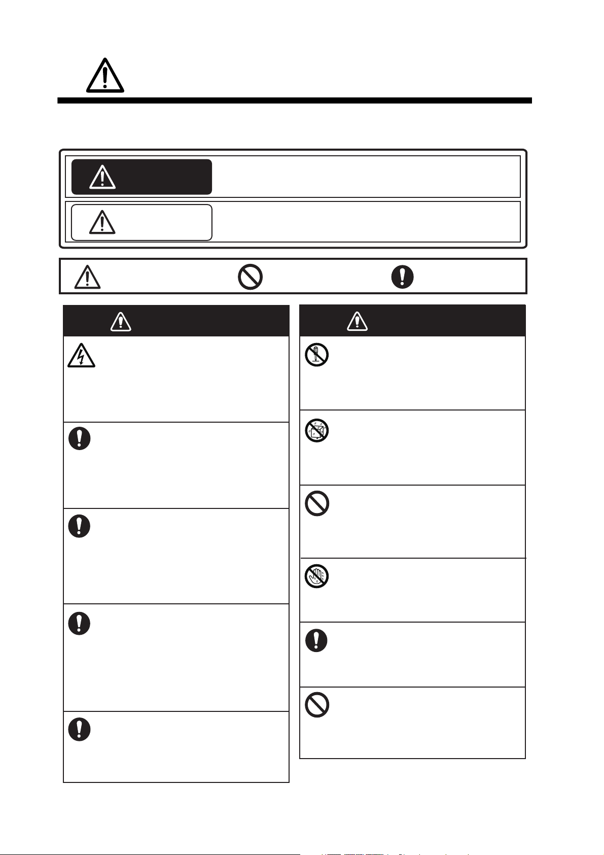
WARNINGWARNING
WARNING
Indicates a potentially hazardous situation which, if not avoided,
could result in death or serious injury.
CAUTION
Indicates a potentially hazardous situation which, if not avoided,
can result in minor or moderate injury.
Warning, Caution
Mandatory Action
Prohibitive Action
WARNINGWARNING
ELECTRICAL SHOCK HAZARD
Do not open the equipment.
Hazardous voltage exists inside the
equipment. Refer repair to authorized
service personnel.
Immediately turn off the power at the
switchboard if something is dropped
into the equipment.
Continued use of the equipment can
cause fire or electrical shock.
Immediately turn off the power at the
switchboard if the equipment is
emitting smoke or fire.
Continued use of the equipment can
cause fire or electrical shock. Contact a
FURUNO agent for service.
Immediately turn off the power at the
switchboard if the equipment shows
any abnormality.
If the unit exhibits any sign of abnormal
heat or sound, turn the power off at the
switchboard and consult your local
dealer.
Do not disassemble or modify the
equipment.
Fire, electrical shock or injury can
result.
Keep the equipment away from rain
and water splash.
Fire, electrical shock or injury can
result if water leaks into the equipment.
Do not put containers with liquids on
the top of the equipment.
Fire, electrical shock or injury can
result.
Do not maneuver the vessel based
solely on the depth indication shown
on the screen.
Grounding of the vessel can occur.
Do not operate the equipment with
wet hands.
Electrical shock can result.
Use the proper fuse.
Use of an incorrect fuse can damage
the equipment and can cause fire.
The operator must read the applicable safety instructions before attempting to operate the
equipment.
Use only the specified power and
signal cable.
Fire or damage to the equipment can
result if a different cable is used.
ii
Page 5
SAFETY INSTRUCTIONS
CAUTION
CAUTION
CAUTION
Do not use depth information for
navigation while the picture advance
speed is set to "stop".
The depth indication is not refreshed
while the picture is stopped. Use of
depth data for navigation in this case
could lead to grounding or other
dangerous situation.
Do not transmit with the transducer
out of water.
The transducer will be damaged.
Keep the following points in mind
regarding cables.
• Keep the cables away from lubricants
and fuels.
• Avoid areas where the cable may be
damaged.
• Do not paint the cables.
Solvents such as toluene, contained
in paints, can damage the cable’s
protective covering.
CAUTION
Adjust the gain properly.
Too little gain may present no picture.
Too much gain shows excessive noise
on the picture.
Keep the bottom echo and depth
indication shown stably.
Unstable bottom echo and depth
indication can result in grounding if the
vessel is steered acoording to the
informations on the display. If unstable,
adjust the setting of [Bottom Level] or
[TX Power].
Do not connect/disconnect the
cables connected to the processor
unit while turning the power on.
The unit may be damaged.
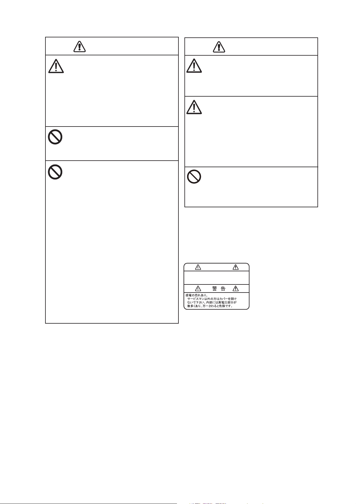
Warning Label
A warning label is attached to the Transceiver
Unit. Do not remove the label. If the label is
missing or illegiblem contact your local dealer
regarding a replacement.
• Do not cut the cables.
The cables may be damaged or
become corroded.
• Do not carry the equipment using only
the cables.
The cables may be damaged or
become disconnected.
WARNING
To avoid electrical shock, do not
remove cover. No user-serviceable
parts inside.
Name: Warning Label (1)
Type: 86-003-1011-3
Code No.: 100-236-233-10
iii
Page 6

TABLE OF CONTENTS
FOREWORD ..................................................................................................................vii
SYSTEM CONFIGURATION ..........................................................................................ix
1. OPERATION ..........................................................................................................1-1
1.1 Trackball Control Unit.................................................................................................1-1
1.2 How to Turn the Power On/Off................................................................................... 1-2
1.3 Fish Finder Display .................................................................................................... 1-2
1.3.1 Display overview ............................................................................................ 1-2
1.3.2 How to interpret the header............................................................................ 1-3
1.3.3 How to interpret the footer.............................................................................. 1-3
1.3.4 How to use the InstantAccess bar
1.3.5 InstantAccess bar™ icons list ........................................................................ 1-5
1.4 How to Change Display Modes.................................................................................. 1-9
1.4.1 How to change the display mode for the FCV-2100 ...................................... 1-9
1.4.2 How to adjust the split screen division ......................................................... 1-10
1.5 Picture Advance ....................................................................................................... 1-11
1.5.1 Picture advance for FCV-2100 and external fish finders.............................. 1-11
1.5.2 Picture advance for external fish finders where [External Fish Finder Window] is
set to [On] at installation1-12
1.6 How to Adjust the Gain ............................................................................................ 1-13
1.6.1 How to adjust the gain for the FCV-2100.....................................................1-13
1.6.2 How to adjust the gain for external fish finders where [External Fish Finder] is
set to [Off] at installation1-13
1.6.3 How to adjust the gain for external fish finders where [External Fish Finder
Window] is set to [On] at installation1-14
1.7 How to Shift the Display Range ............................................................................... 1-14
1.7.1 How to shift the display range for the FCV-2100 and external fish finders .. 1-15
1.7.2 How to shift the display range for external fish finders where [External Fish
Finder Window] is set to [On] at installation1-15
1.8 How to Change the Range....................................................................................... 1-16
1.8.1 How to change the range for FCV-2100 and external fish finders ............... 1-16
1.8.2 How to change the range for external fish finders where [External Fish Finder
Window] is set to [On] at installation1-17
1.9 How to Reject Interference.......................................................................................1-17
1.9.1 Interference rejection for the FCV-2100....................................................... 1-17
1.9.2 Interference rejection for external fish finders where [External Fish Finder
Window] is set to [Off] at installation1-18
1.9.3 Interference rejection for external fish finders where [External Fish Finder
Window] is set to [On] at installation1-18
1.10 How to Use the Smoothing Function........................................................................ 1-19
1.10.1 How to use smoothing for the FCV-2100..................................................... 1-19
1.10.2 How to use smoothing for external fish finders where [External Fish Finder
Window] is set to [Off] at installation1-19
1.10.3 How to use smoothing for external fish finders where [External Fish Finder
Window] is set to [On] at installation1-20
1.11 How to Reject Low Level Noise (Clutter) ................................................................. 1-20
1.11.1 How to reject clutter for the FCV-2100......................................................... 1-20
1.11.2 How to reject clutter for external fish finders where [External Fish Finder
Window] is set to [Off] at installation1-21
1.11.3 How to reject clutter for external fish finders where [External Fish Finder
Window] is set to [On] at installation1-21
1.12 Zoom Display ........................................................................................................... 1-22
™
...............................................................1-4
iv
Page 7

TABLE OF CONTENTS
1.12.1 Bottom lock mode.........................................................................................1-22
1.12.2 Bottom zoom mode ......................................................................................1-23
1.12.3 Marker zoom mode ......................................................................................1-23
1.12.4 Bottom discrimination mode .........................................................................1-24
1.13 How to Switch Between Display Color Modes..........................................................1-25
1.14 How to Use the A-Scope Display .............................................................................1-26
1.15 How To Show/Hide The Depth Indication.................................................................1-26
1.16 How To Show/Hide The Depth Scale .......................................................................1-26
1.17 How to Measure Depth.............................................................................................1-27
1.18 How To Show/Hide The Minute Marker....................................................................1-27
1.19 How To Show/Hide The Color Bar ...........................................................................1-27
1.20 External Fish Finder Display.....................................................................................1-28
1.20.1 How to change the display mode on the external fish finder screen ............1-29
1.20.2 How to use the ACCU-FISH
1.20.3 How to display seabed composition (bottom discrimination)........................1-31
1.21 How to Set, Show and Hide Alarms .........................................................................1-33
1.21.1 How to activate/deactivate the alarms..........................................................1-34
1.21.2 How to set the alarms...................................................................................1-35
1.22 How To Show/Hide Displayed Data .........................................................................1-36
1.23 How to Inscribe TLL Lines ........................................................................................1-37
1.24 How to Use Scroll Back Mode ..................................................................................1-37
1.25 How to Erase Weak Echoes.....................................................................................1-38
1.25.1 How to erase weak echoes for the FCV-2100 and external fish finders ......1-38
1.25.2 How to erase weak echoes for external fish finders where [External Fish Finder
Window] is set to [On] at installation1-39
1.26 How to Adjust TVG (Time Varied Gain)....................................................................1-39
1.26.1 How to adjust TVG for FCV-2100.................................................................1-40
1.26.2 How to adjust TVG for external fish finders where [External Fish Finder Window]
is set to [Off] at installation1-41
1.26.3 How to adjust TVG for external fish finders where [External Fish Finder Window]
is set to [On] at installation1-41
1.27 How to Save and Load Settings ...............................................................................1-42
1.27.1 How to save settings ....................................................................................1-42
1.27.2 How to load settings .....................................................................................1-43
1.28 How to Undo/Redo Operations.................................................................................1-44
™
feature..........................................................1-30
2. GRAPH FUNCTIONS ............................................................................................2-1
2.1 How to Show/Hide Graphs .........................................................................................2-1
2.2 Fish Size Graph..........................................................................................................2-2
2.2.1 How to show/hide the fish size graph.............................................................2-3
2.2.2 How to set the method of measurement ........................................................2-3
2.2.3 Entire Area .....................................................................................................2-3
2.2.4 Specific Range ...............................................................................................2-4
2.2.5 Bottom Trace..................................................................................................2-5
2.2.6 Specific Area ..................................................................................................2-6
2.2.7 How to change graph settings........................................................................2-7
2.2.8 How to calibrate the target echo strength.......................................................2-8
2.3 Target Graphs ............................................................................................................2-9
2.3.1 Vertical target graph.......................................................................................2-9
2.3.2 Horizontal target graph.................................................................................2-10
2.3.3 How to change the graph scale (target graphs only)....................................2-10
2.4 Sonde Graph ............................................................................................................2-11
2.5 Temp Graph .............................................................................................................2-11
2.6 Hardness Graph .......................................................................................................2-12
3. STILL IMAGES & DATA RECORDING................................................................. 3-1
v
Page 8

TABLE OF CONTENTS
3.1 Still Images (Screenshots) .........................................................................................3-1
3.1.1 How to set the save destination for images ................................................... 3-1
3.1.2 How to take a still image (screenshot) ........................................................... 3-2
3.1.3 How to take still images at a set interval........................................................3-2
3.1.4 How to replay a still image ............................................................................. 3-3
3.1.5 How to copy images from internal to external memory..................................3-4
3.1.6 How to delete image files............................................................................... 3-4
3.2 Echo Data Recording and Playback .......................................................................... 3-5
3.2.1 How to record echo data................................................................................ 3-5
3.2.2 How to play back recorded echo data............................................................ 3-6
3.3 How to Select an External Memory Device................................................................3-8
4. ADVANCED SETTINGS ........................................................................................4-1
4.1 How to Access the Advanced Settings Menu ............................................................ 4-1
4.2 Sounder Menu............................................................................................................4-2
4.3 Display Menu ............................................................................................................. 4-3
4.4 Measurement Menu ...................................................................................................4-4
4.5 Alarm Menu................................................................................................................ 4-5
4.6 External Fish Finder Menu.........................................................................................4-5
4.6.1 Sounder menu................................................................................................ 4-6
4.6.2 Calibration menu............................................................................................ 4-7
4.6.3 TX/RX menu................................................................................................... 4-8
4.7 System Menu .............................................................................................................4-9
4.7.1 Range menu................................................................................................... 4-9
4.7.2 TX/RX menu................................................................................................. 4-10
4.7.3 Control unit menu......................................................................................... 4-11
4.7.4 User Interface Settings menu....................................................................... 4-12
4.7.5 Calibration menu.......................................................................................... 4-13
4.7.6 Stabilization menu........................................................................................4-14
4.7.7 Mode menu .................................................................................................. 4-15
4.7.8 Tests menu .................................................................................................. 4-17
4.8 External Fish Finder Window ...................................................................................4-17
4.8.1 Sounder menu.............................................................................................. 4-18
4.8.2 Display menu ............................................................................................... 4-19
4.8.3 Measurement menu ..................................................................................... 4-20
4.8.4 System menu ............................................................................................... 4-20
5. MAINTENANCE AND TROUBLESHOOTING.......................................................5-1
5.1 Maintenance...............................................................................................................5-1
5.2 Trackball Maintenance ............................................................................................... 5-2
5.3 Fuse Replacement ..................................................................................................... 5-2
5.4 Battery Replacement..................................................................................................5-3
5.5 Troubleshooting ......................................................................................................... 5-3
5.6 Error Messages and Icons ......................................................................................... 5-4
5.7 Test Menu ..................................................................................................................5-6
5.7.1 How to run a diagnostic test........................................................................... 5-7
5.7.2 Communication Port Monitor.......................................................................... 5-7
5.7.3 How to test the control unit............................................................................. 5-9
5.7.4 LCD Test........................................................................................................ 5-9
APPENDIX 1 MENU TREE .......................................................................................AP-1
APPENDIX 2 SCREEN LAYOUTS ...........................................................................AP-5
SPECIFICATIONS .....................................................................................................SP-1
INDEX..........................................................................................................................IN-1
vi
Page 9

FOREWORD
A Word to the Owner of the FCV-2100
Congratulations on your choice of the FCV-2100 Fish Finder and Fish Size Indicator. We are confident you will see why the FURUNO name has become synonymous with quality and reliability.
Since 1948, FURUNO Electric Company has enjoyed an enviable reputation for innovative and
dependable marine electronics equipment. This dedication to excellence is furthered by our extensive global network of agents and dealers.
Your equipment is designed and constructed to meet the rigorous demands of the marine environment. However, no machine can perform its intended function unless properly installed and
maintained. Please carefully read and follow the operation and maintenance procedures set forth
in this manual.
We would appreciate feedback from you, the end-user, about whether we are achieving our purposes.
Thank you for considering and purchasing FURUNO.
Features
The FCV-2100 is a color fish finder with split-beam technology for estimating fish sizes. The system is comprised of a Trackball Control Unit, Processor Unit, Transceiver Unit and Transducer.
The FCV-2100 shows echoes on a monitor (local supply).
The main features of the FCV-2100 are:
• Wide-band technology allows the display of high-resolution fish echoes.
• Fish-size graph allows estimation of fish distribution at a glance.
• Target location graph allows tracking of a designated fish target.
• Hardness graph allows monitoring of the seabed hardness.
• Data recording and screen-shot function allow easy review of past echoes and recordings.
• Scroll-back mode allows the user to review past data.
• Gain changes made at the FCV-2100 are applied to all screens currently displayed on the FCV2100 (excludes external fish finders).
• Recorded data can be saved to an external recording device.
• Display up to three separate echo images; available with the connection of an externally networked fish finder (external fish finder), such as DFF3/DFF1-UHD.
• Constant stable display of echoes is achievable with the use of the heave offset function (re-
quires connection to a SATELLITE COMPASS
™
).
• Location of fish schools can be output to connected navigational equipment.
• Easy to see fish sizes with the ACCU-FISH
play and an external fish finder.)
• Seabed composition can be displayed on-screen in graphical or colored format. (Requires connection to an external display and an external fish finder.)
™
feature. (Requires connection to an external dis-
vii
Page 10
FOREWORD
Cautionary notes regarding external memory devices
• Do not use password-locked memory devices.
• Do not remove or disconnect the external device while data is being saved or loaded. This can
cause data corruption or loss.
• Do not connect, or disconnect, external devices when the FCV-2100 is turned on. Turn the power to the FCV-2100 off before connecting or disconnecting an external device.
• For external hard drives, drives with a separate, external power supply are recommended.
• When recording echo data (see section 3.2), a device with 500 GB capacity or higher is recommended.
• When recording echo data and saving screenshots, connect the external device to the USB port
of the processor unit. Do not connect external memory devices to the Trackball Control Unit’s
USB port.
• Log output can require up to 2.4 GB capacity. Where the external device has insufficient capacity, the log is output until the capacity is full. Any log entries after this point are not saved.
• The following external devices are known to be compatible with this system:
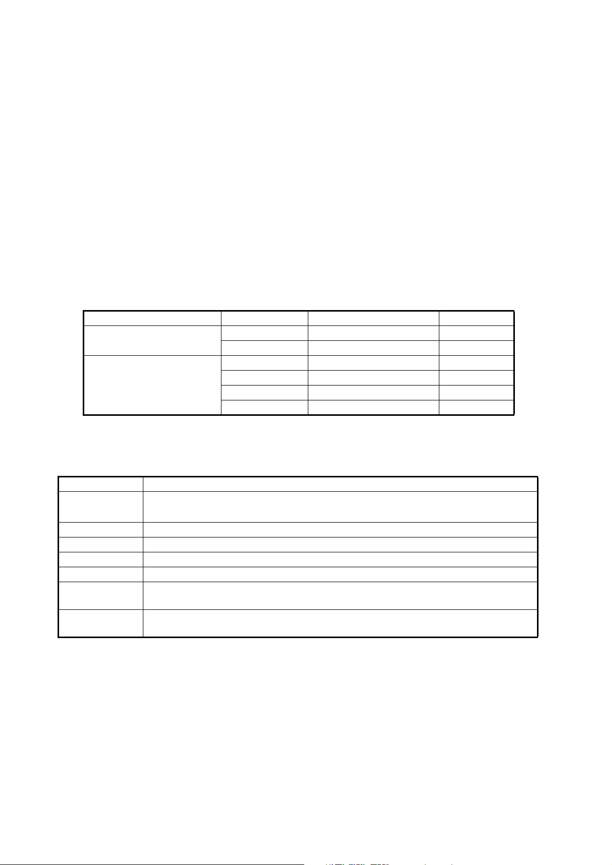
External device Maker Model Capacity
USB Flash Memory TDK UFD32GE-SLBKA 32 GB
Silicon Power SP008GBUF2M01V1K 8 GB
USB External Hard Drive I-O DATA HDCL-UT1.0KB 1 TB
BUFFALO HD-LC1.0U3-BKD 1 TB
ELECOM LCH-MN1TU3TVS 1 TB
TOSHIBA HD-ED10TK 1 TB
Terminology standards used in this manual
For the sake of brevity, procedures in this manual use the following terminology:
Terminology Meaning
Select Use the trackball to move the cursor onto the item indicated, then left-click.
™
For example, "Select the [Display] icon from the InstantAccess bar
Left-click Press the Left button once.
Double-click Press the Left button two times, in quick succession.
Right-click Press the Right button once.
Scroll Rotate the Scrollwheel.
Drag and drop Highlight the item with the cursor, then press and hold the Left button. Use the
Trackball to move, or “drag”, the item. Release the Left button to “drop” the item.
External Fish
Finder
Used in reference to an external echo sounder connected to the FCV-2100. For
example, DFF3.
.".
viii
Page 11
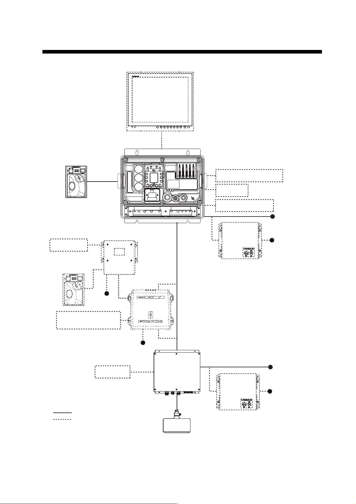
Monitor
Processor Unit
FCV-2101
Trackball
Control Unit
TCU-001
Trackball
Control Unit
TCU-001
Navigational Equipment
Satellite Compass™
Net Sonde
24 VDC
24 VDC
24 VDC
24 VDC
100/110/220/
230 VAC, 1ø,
50/60 Hz
100/110/220/
230 VAC, 1ø,
50/60 Hz
Rectifier
PR-62
Rectifier
PR-62
Transceiver Unit
FCV-2102
Transducer
FCV-2103
USB Device Server
UDS-001
Ethernet Hub
HUB-101
Network Fish Finder
(DFF3/DFF1-UHD)
USB Device
External KP
: Standard supply
: Optional/local supply
SYSTEM CONFIGURATION
ix
Page 12

SYSTEM CONFIGURATION
This page is intentionally left blank.
x
Page 13
1. OPERATION
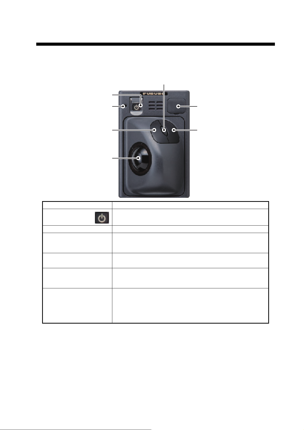
1.1 Trackball Control Unit
Scrollwheel
Power button
Power indicator
Trackball
Key Function/Description
Power button
Trackball Moves the cursor.
Left button Short press: Select the item highlighted with the cursor.
Right button
Scrollwheel Rotate (scroll): Change the setting for the selected item.
USB port cover Remove to access the USB port. USB flash memory can be in-
Press to turn the power on or off.
Double-click: Inscribe a line (TLL).
Drag & Drop: Move the selected window/marker line etc.
• Show/hide the InstantAccess bar
• Cancel the selected operation.
Short press: Take a screenshot (still image).
Long press: Replay screenshots.
serted here. When the USB port is not in use, cover the USB port
with the port cover.
Note: Do not use this port to connect external memory devices
for data recording or saving screenshots.
USB port cover
Right buttonLeft button
™
.
1-1
Page 14
1. OPERATION
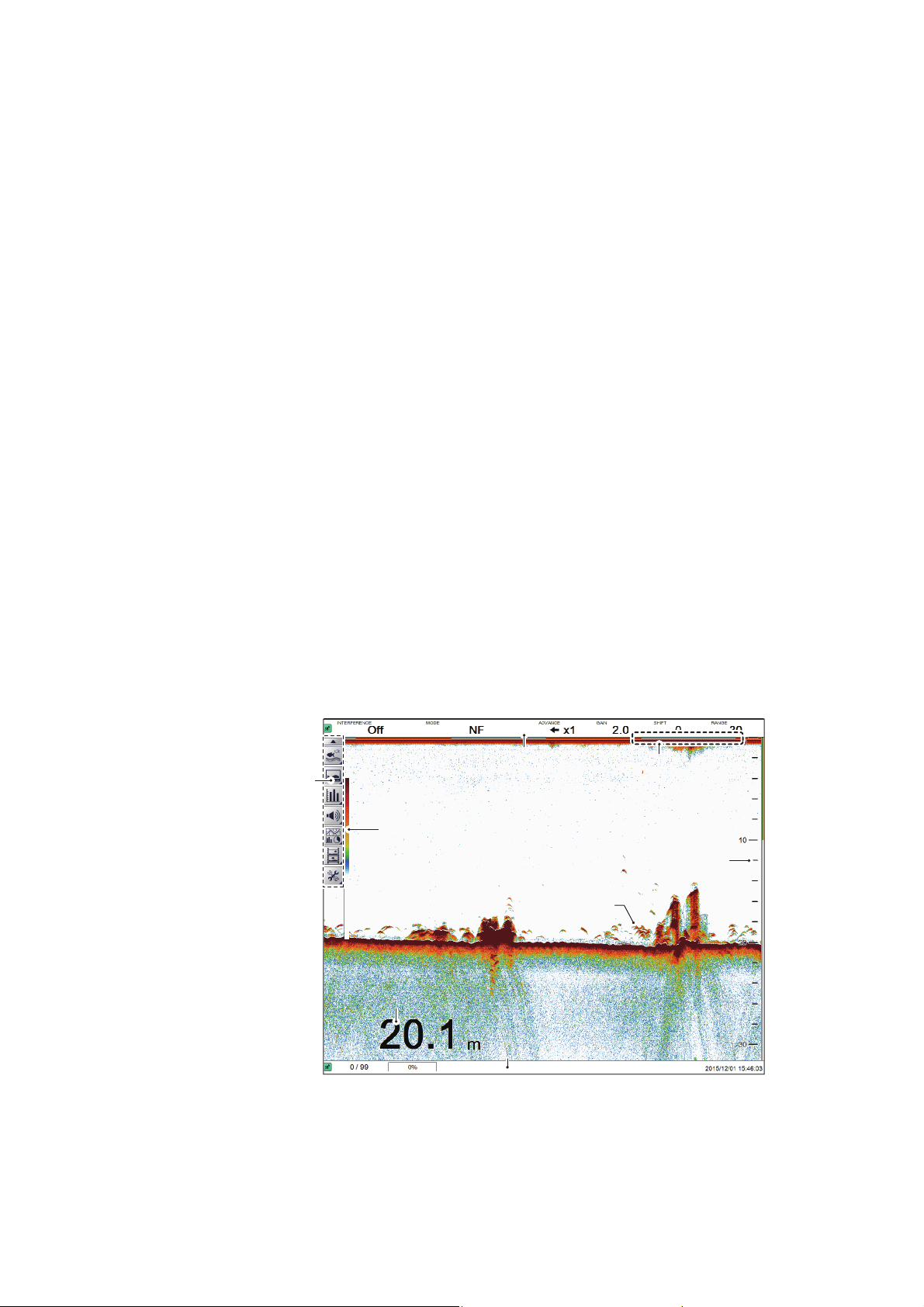
InstantAccess bar
TM
HeaderHeader
Minute marker* and
transmission line.
Minute marker* and
transmission line.
Color barColor bar
Current depthCurrent depth
Depth scaleDepth scale
Fish schoolFish school
*: Each minute marker “bar ” denotes 30 seconds.
FooterFooter
1.2 How to Turn the Power On/Off
Open the power button cover on the Trackball Control Unit, then press the power button. An audible “beep” sound indicates that the power is now on, and the start-up
screen is displayed.
When the start-up procedure is complete, the last used screen is displayed.
Where the setting for the power indicator brightness ([System] menu → [Control Unit]
→ [Brightness]) is set to other than [0], the Trackball Control Unit is lit to indicate that
the power is on.
To turn the power off, open the power button cover, then press the power button.
Note 1: Always use the Trackball Control Unit to turn the system on or off. If the system is turned off from a switchboard or by other means, changes made to settings are
not saved.
Note 2: Although the system is turned off, the system uses a small amount of power
(Processor Unit: 60mA maximum; Transceiver: 280mA maximum). When the system
is not used for a lengthy period of time, turn the system off normally, then turn the system’s power off from the switchboard.
1.3 Fish Finder Display
1.3.1 Display overview
The figure below shows a typical display example. Some indications are not shown in
this example, however all functions and indications are covered later in this manual.
1-2
Page 15
1. OPERATION
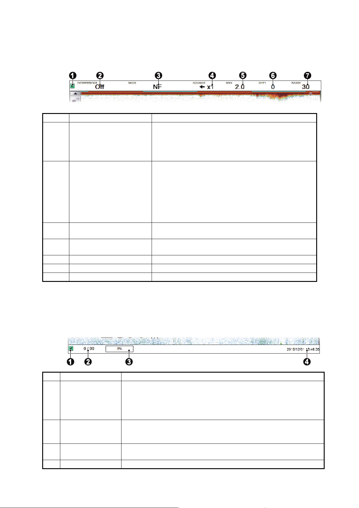
1.3.2 How to interpret the header
The header contains various settings and controls, all accessible with the cursor. Select an indication on the header to adjust that function.
No. Name Description
1 “Pinned” icon Select the “Pinned” icon to “pin” or “unpin” the header.
A “pinned” header is always visible at the top of the
screen. An “unpinned” header is hidden until the cursor is
placed on the header’s location.
This icon is shown in green color when “pinned”.
2 Miscellaneous settings Select the indication to activate the current function, then
scroll to select the desired setting. The functions available
from this section of the header are:
• Interference rejection. See section 1.9.
• Smoothing. See section 1.10.
• Clutter. See section 1.11.
• Zoom mode. See section 1.12.
• External fish finder Gain. See section 1.6.2.
3 [MODE] Select the Display mode. See section 1.4 for available
modes.
4 [ADVANCE] Select the speed at which echoes appear on the screen.
See section 1.5.
5 [GAIN] Select the transducer sensitivity level. See section 1.6.
6 [SHIFT] Shift the displayed area. See section 1.7.
7 [RANGE] Change the displayed range. See section 1.8.
1.3.3 How to interpret the footer
The footer displays the date and time, how many still images are saved, the amount
of space available in the external memory.
No. Name Description
1 “Pinned” icon The footer can be “pinned” or “unpinned”.
A “pinned” footer is always visible at the bottom of the screen.
An “unpinned” footer is hidden until the cursor is placed on the footer’s
location.
This icon is shown in green color when “pinned”.
2 Internal memory
image counter
3 External memory
capacity
4 Current date/time Shows the current date and time.
Shows the number of still images stored in the internal memory and the
total capacity available. For example, if the indication reads "9/99", this
means that nine images are saved and the total capacity is 99 images.
Shows the available capacity on the external memory device.
1-3
Page 16
1. OPERATION
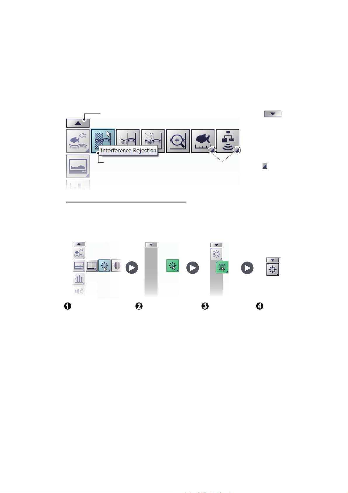
Display the icon you
want to store,
highlight it with the
cursor, then press
and hold the left
button.
Drag the icon
away from the
menu with the
trackball. The
shortcut bar
appears.
Drag and drop
the icon to the
shortcut bar.
The icon is
now stored
on the
shortcut bar.
Shorcut barShorcut bar
1.3.4 How to use the InstantAccess bar
The InstantAccess bar™ contains the menus for functions and features, all in one
compact icon-based format. You can show/hide the InstantAccess bar™ at any time
using the icon at the top of the bar. Another method to show/hide the InstantAccess
bar™ is to place the cursor on a non-interactive section of the display, then right-click.
To access a feature or function, select the appropriate icon. The menu bar for that icon
appears. The example below shows the [Sounder] section of the InstantAccess bar™.
When the “arrow” inside the icon points down, as shown here,
it indicates that the InstantAccess bar
Place the cursor over an icon to
highlight it and show the tooltip.
How to Create and Remove Shortcuts
™
TM
is hidden.
The small triangle “ ” , at
the bottom right of an icon,
indicates that there is a
menu available for that icon.
Most icons displayed on the InstantAccess bar™ can be stored as shortcuts. The
shortcuts are displayed when the InstantAccess bar™ is hidden. Up to ten icons can
be assigned to the shortcut bar. To assign an icon to the shortcut bar, do the following:
Note: [Internal Settings] save slot icons (see section 1.27) cannot be stored as shortcuts.
To remove an icon from the shortcut bar:
1. Hide the InstantAccess bar
™
to show the shortcut bar.
1-4
2. Highlight the icon to be removed from the shortcut bar.
3. Drag and drop the icon away from the shortcut bar.
The icon is no longer shown in the shortcut bar.
Page 17
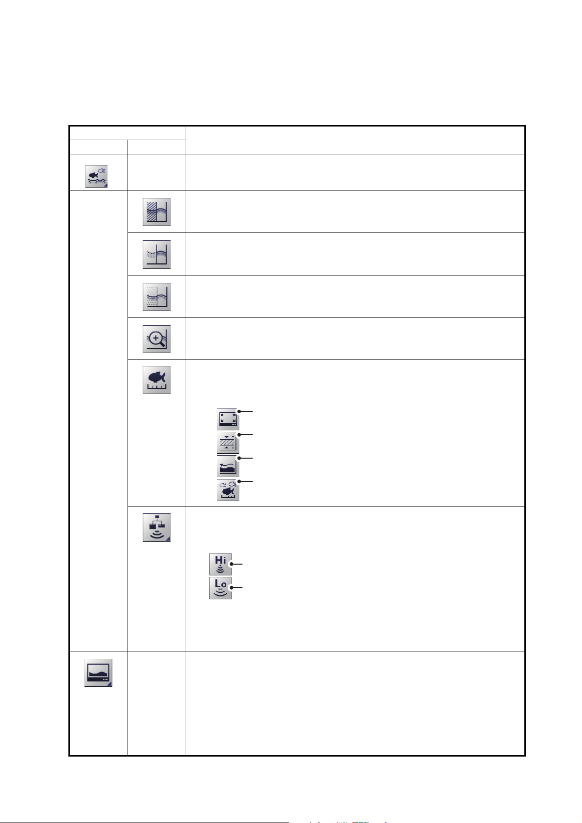
1.3.5 InstantAccess bar™ icons list
Select to adjust the high frequency external fish finder gain.
Select to adjust the low frequency external fish finder gain.
The table below shows the InstantAccess bar™ menus, their respective menu items
and available options, along with a brief description. For full details on each menu/
function, see the respective sections of the manual.
1. OPERATION
Icon
Menu Item
Description/Options
[Sounder] menu.
Select this icon to access the sounder-related settings.
[Interference Rejection] icon.
Select this icon to access the [Interference Rejection] function (see
section 1.9 for details).
[Smoothing] icon.
Select this icon to access the [Smoothing] function (see section 1.10 for
details).
[Clutter] icon.
Select this icon to access the clutter (low level noise reduction) function
(see section 1.11 for details).
[Zoom Mode] icon.
Select this icon to access the zoom functions (see section 1.12 for details).
[Measure Fish Size] icon.
Select this icon to access the fish measurement area settings (see
section 2.2.2 for details). The available settings are:
Measure fish at any location on the display.
See section 2.2.2 for details.
Only measure fish within a specified depth range.
See section 2.2.3 for details.
Only measure fish that appear near the seabed.
See section 2.2.4 for details.
Only measure fish within a specified are on the display.
See section 2.2.5 for details.
[External Fish Finder Gain] icon.
Select this icon to adjust the external fish finder gain (see section 1.6 for
details). The available options are:
Note: The [External Fish Finder Gain] icon is not available when there is
no external fish finder connected, or if the [External Fish Finder Window]
menu option is set to [On] at installation.
[Display] menu.
Select this icon to access the display-related settings.
1-5
Page 18
1. OPERATION
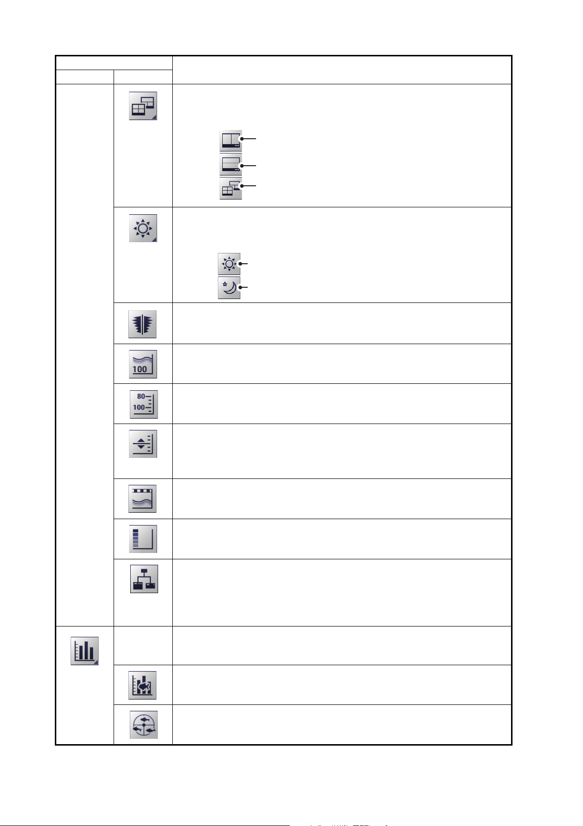
Set the display colors for Day-time viewing.
Set the display colors for Night-time viewing.
Icon
Menu Item
Description/Options
[Display Division] icon.
Select this icon to change the manner in which the display is divided (see
section 1.4). The available options are:
Divide the display vertically.
Divide the display horizontally.
Divide the display in a combination of
horizontal and vertical split screens.
[Window Color] menu.
Select this icon to change the display colors to suit day or night viewing
(see section 1.13 for details). The available options are:
[A-Scope] icon.
Select to show/hide the A-Scope (see section 1.14).
[Depth] icon.
Select to show/hide the depth indication (see section 1.15).
[Depth Scale] icon.
Select to show/hide the depth scale (see section 1.16).
[VRM] icon.
Select to show/hide the VRM line (See section 1.17).
Note: When MZ (Marker Zoom) is selected, the VRM is constantly displayed, regardless of VRM settings.
[Minute Marker] icon.
Select to show/hide the minute marker (see section 1.18).
[Color Bar] icon.
Select to show/hide the color bar (see section 1.19).
[External Echo Sounder] icon.
Select to show/hide echoes from the external echo sounder on the sub
display.
Note: The [External Echo Sounder] icon is not available when the [External Fish Finder Window] menu option is set to [Off] at installation.
[Graph] menu.
Select this icon to access the graph functions.
See chapter 2 for details.
[Fish Size Graph].
Select this icon to activate/deactivate the fish size graph and measurement functions (see section 2.2).
[Vertical Target Graph].
Select this icon to activate/deactivate the vertical target graph (see
section 2.3.1).
1-6
Page 19
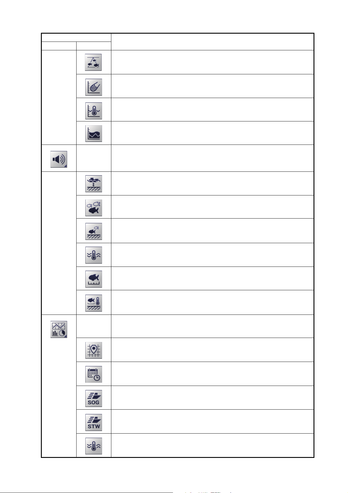
1. OPERATION
Icon
Menu Item
Description/Options
[Horizontal Target Graph].
Select this icon to activate/deactivate the horizontal target graph (see
section 2.3.2).
[Sonde Graph].
Select this icon to activate/deactivate the sonde graph (see section 2.4).
[Temp Graph].
Select this icon to activate/deactivate the water temperature graph (see
section 2.5).
[Hardness Graph].
Select this icon to activate/deactivate the seabed hardness graph (see
section 2.6).
[Alarm] menu.
Select this icon to activate/deactivate alarms.
See section 1.21 for details.
[Bottom Alarm] icon.
Select this icon to activate/deactivate the seabed depth alarm.
[Fish Alarm] icon.
Select this icon to activate/deactivate the fish alarm.
[Bottom Fish Alarm] icon.
Select this icon to activate/deactivate fish alarm for fish near the seabed.
[Water Temperature Alarm] icon.
Select this icon to activate/deactivate the water temperature alarm.
[Fish Size Graph Alarm] icon.
Select this icon to activate/deactivate the fish size alarm.
[Combined Alarm] icon.
Select this icon to activate/deactivate the combined alarm.
[Data Display] menu.
Select this icon to access settings for external data received.
See section 1.22 for details.
[Own Ship Position] icon.
Select this icon to show/hide Own Ship latitude and longitude.
[Time and Date] icon.
Select this icon to show/hide the time and date.
[Speed(SOG)] icon.
Select this icon to show/hide your vessel’s speed over the ground.
[Speed(STW)] icon.
Select this icon to show/hide your vessel’s speed through the water.
[Temperature] icon.
Select this icon to show/hide the water temperature.
1-7
Page 20
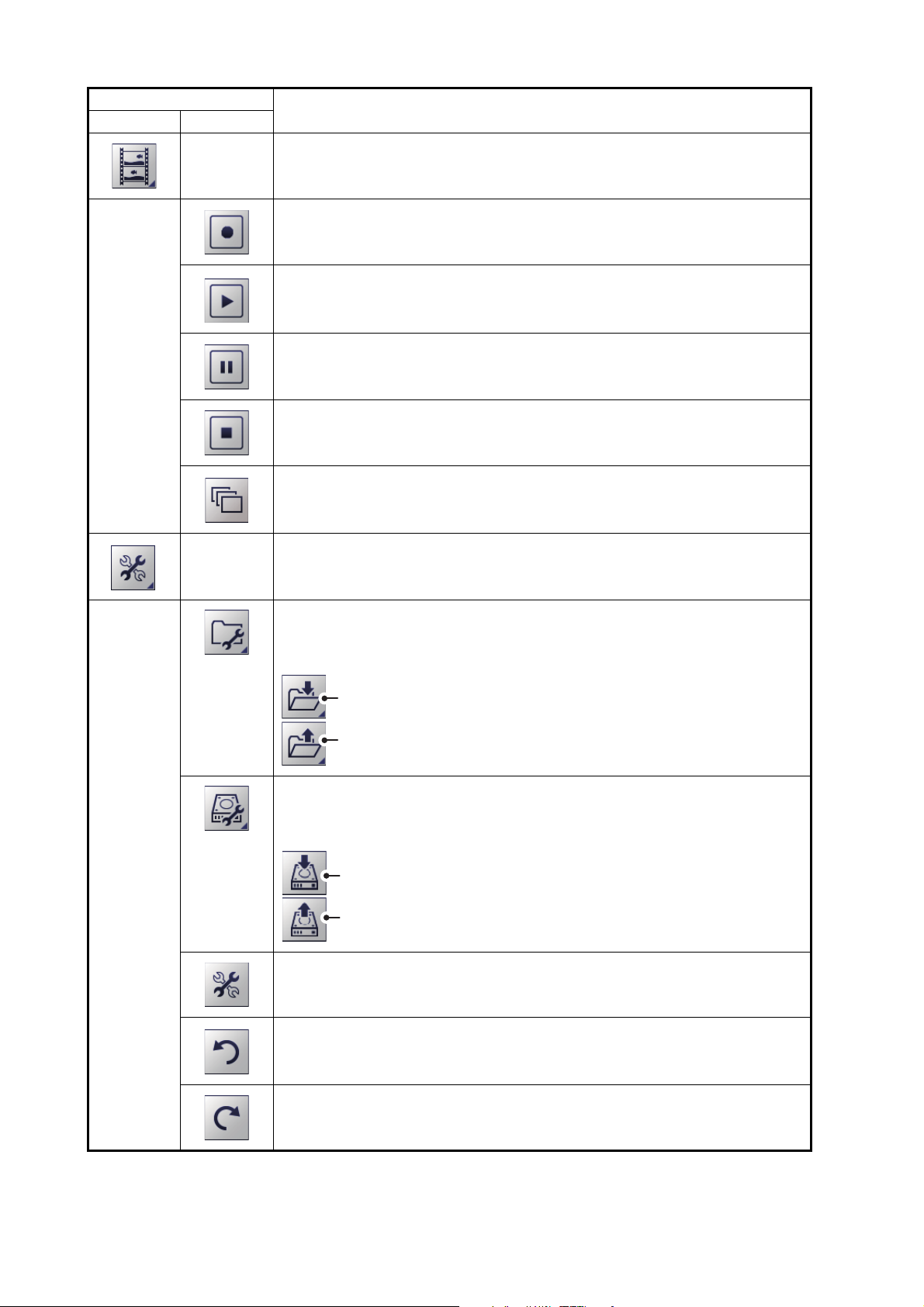
1. OPERATION
[
Save Settings] icon.
[
Load Settings] icon.
[
Save External Unit Settings] icon.
[
Load External Unit Settings] icon.
Icon
Menu Item
Description/Options
[Echo Recording] menu.
Select this icon to access the echo recording and image recording functions.
[Record] icon.
Select this icon to begin recording echo data (see section 3.2.1).
[Play] icon.
Select this icon to playback echo data (see section 3.2.2).
[Pause] icon.
Select this icon to pause the echo data playback (see section 3.2.2).
[Stop] icon.
• Select this icon to stop echo data recording (see section 3.2.1).
• Select this icon to stop echo data playback (see section 3.2.2).
[Multi-Screenshot Start/Stop] icon.
Select this icon to take multiple screenshots (see section 3.1.3).
[Advanced Settings] menu.
Select this icon to access the advanced settings menu, change various
settings for the FCV-2100 and undo/redo actions.
[Internal Settings] menu.
Select this icon to save/load data to/from the processor unit’s internal
memory (see section 1.27).
[External Settings] menu.
Select this icon to save/load data to/from an external memory device (see
section 1.27).
[Advanced Settings] icon.
Select this icon to access the [Advanced Settings] pop up menu.
See chapter 4 for details.
[Undo] icon.
Select this icon to “undo” the last operation (see section 1.28).
1-8
[Redo] icon.
Select this icon to “redo” the last operation (see section 1.28).
Page 21
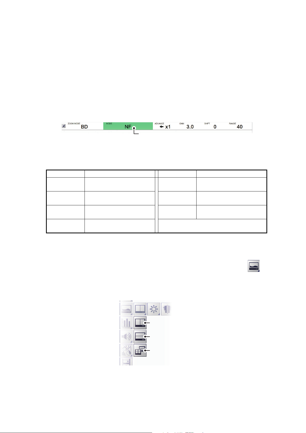
1.4 How to Change Display Modes
[
MODE] indication
The FCV-2100 has several display modes available, some of which can be displayed
in split screen.
1.4.1 How to change the display mode for the FCV-2100
Note: To change the display mode on the external fish finder window, see
section 1.20.1.
1. Display the header if it is not “pinned”. When the header is displayed, go to step 2.
2. Select the [MODE] indication on the header. The indication is now highlighted in
a green color.
3. Scroll to show the desired mode. The available modes depend on the [Mode]
menu settings in the [System] menu. See section 4.7.7 for details.
The table below lists the modes with their abbreviation (as displayed on-screen)
along with the meaning.
Abbreviation Meaning Abbreviation Meaning
NF Normal FCV-2100 mode. BD Bottom Discrimination. See
section 1.12.4.
BL Bottom Lock. See
section 1.12.1.
BZ Bottom Zoom. See
section 1.12.2.
MZ Marker Zoom. See
section 1.12.3.
Note: To display the external fish finder in the mode list, refer to section 4.7.7.
Where External fish Finder Window is set to On at installation, the external fish
finder echoes can be displayed on the sub monitor (see section 1.20).
HE External HF sounder. See
section 4.7.7.
LE External LF sounder. See
section 4.7.7.
1. OPERATION
4. Where two or more sounders are displayed, select the [Display] icon ( ) from
the InstantAccess bar™, then select the [Display Division] icon*.
*: The icon displayed varies depending on the currently selected method of division. See the figure below for the available icons and divisions.
[
Vertical] icon
[
Horizontal] icon
[
Combination] icon
1-9
Page 22
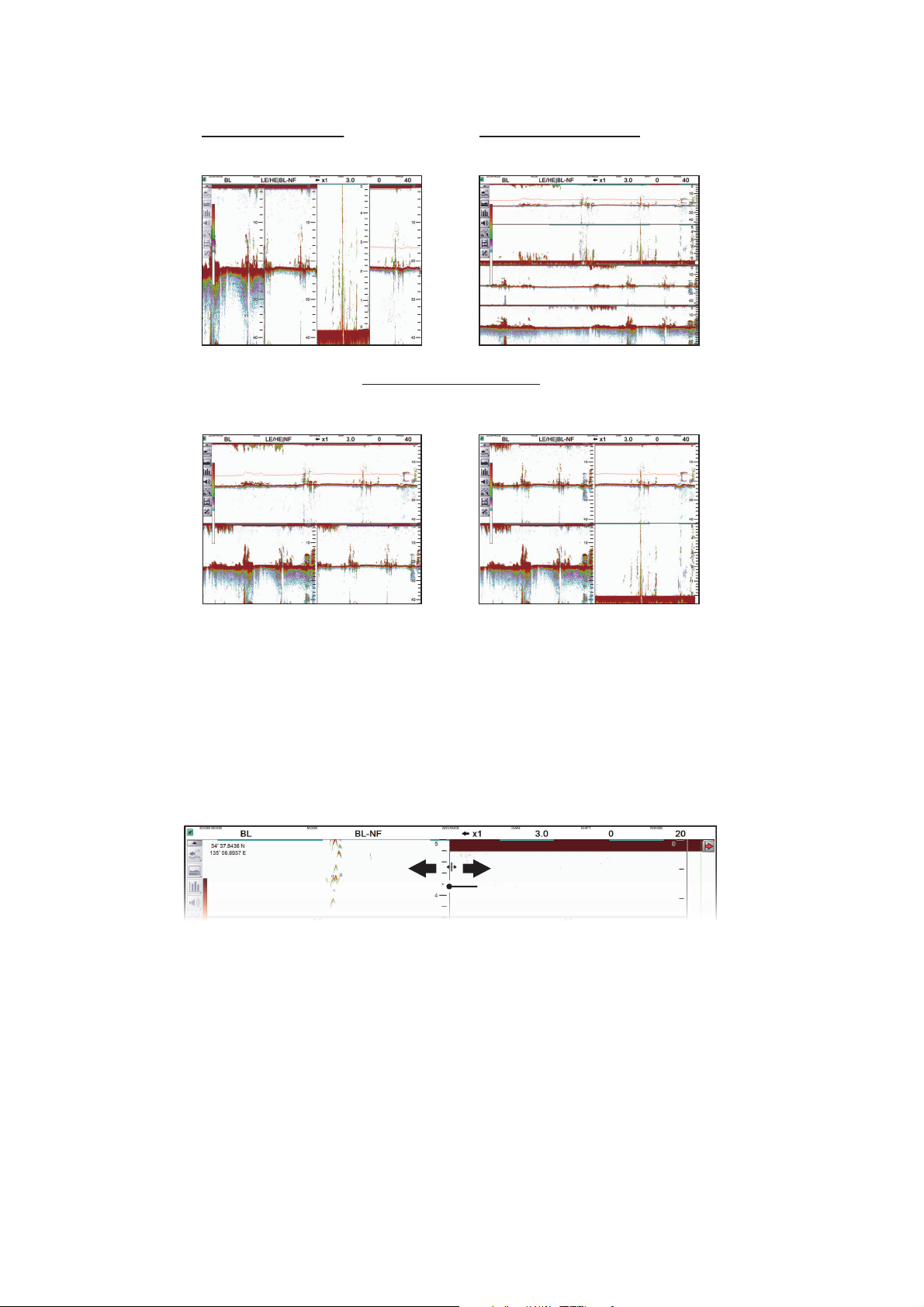
1. OPERATION
Vertical split screens
This example shows a four
sounder configuration.
Horizontal split screens
This example shows a four
sounder configuration.
Combination split screens
(For configurations with only two sounders connected, the combination
screen is the same as the vertical split screen.)
This example shows a three
sounder configuration.
This example shows a four
sounder configuration.
Boundary lineBoundary line
5. Select the method in which you wish to “split” the display.
1.4.2 How to adjust the split screen division
You can adjust the size of each division of a split screen to suit your requirements. To
adjust the size of a split screen, do the following:
1. Select the boundary line between the split screens. The example below shows
vertically split screens.
2. Drag the boundary line to resize the screens as required.
1-10
Page 23
1. OPERATION
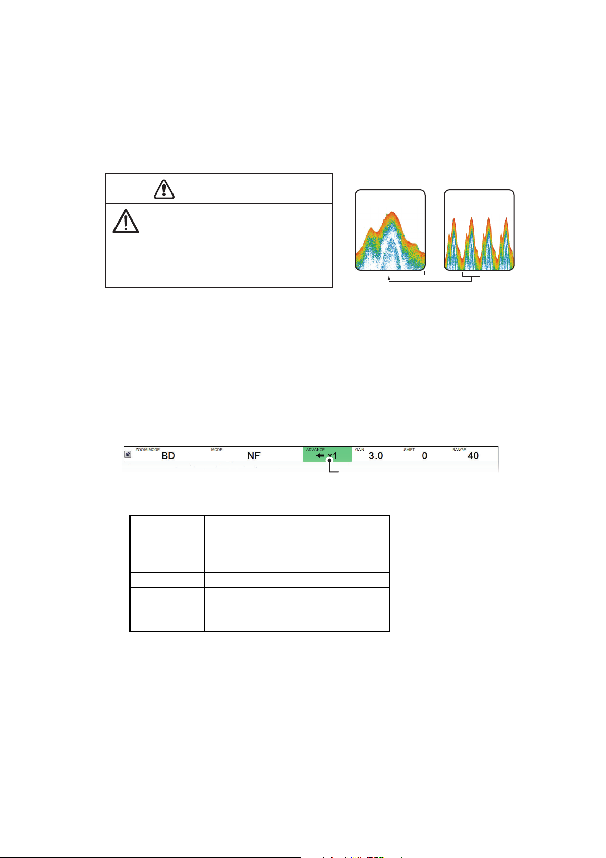
CAUTIONCAUTION
Fast Slow
Neither the picture nor the depth
indication is updated and when the
picture is stopped. For those reasons,
do not steer the vessel while monitoring
the picture/depth indication when the
picture is stopped.
[
ADVANCE] indication
1.5 Picture Advance
The picture advance speed determines how quickly the echoes are displayed onscreen. When setting a picture advance speed, keep in mind that a fast advance
speed will expand echoes horizontally on the screen and a slow advance speed will
contract them. A fast advance speed is useful for observing a rugged seabed closely.
A slow advance speed is useful for observing a smooth seabed.
1.5.1 Picture advance for FCV-2100 and external fish finders
Where [External Fish Finder Window] is set to [Off] at installation, the picture advance
setting is applied to both the FCV-2100 and the external fish finder.
1. Display the header if it is not “pinned”. If the header is already displayed, go to step
2.
2. Select the [ADVANCE] indication on the header. The indication is now highlighted
in a green color.
3. Scroll to select the appropriate advance speed. The table below lists each speed
with a description.
[ADVANCE]
indication
[STOP] Picture is “paused”.
[1/4] One quarter of the normal speed.
[1/2] Half the normal speed.
[×1] Normal speed.
[×2] Twice as fast as normal speed.
[×4] Four times as fast as normal speed.
Description
1-11
Page 24
1. OPERATION
HF
LF
HF
LF
HF
m
Range
Rang
Shift
Interf
n
Col
e
White Marke
Pic
ce
S
thing
Clu
tte
r
250
0
Auto
0%
Off
x1
O
0%
Cal
ibr
ati
on
S
r
S
r
Display
Current picture
advance speed
1.5.2 Picture advance for external fish finders where [External Fish Finder Window] is set to [On] at installation
Where [External Fish Finder Window] is set to [On] at installation, follow the procedure
below.
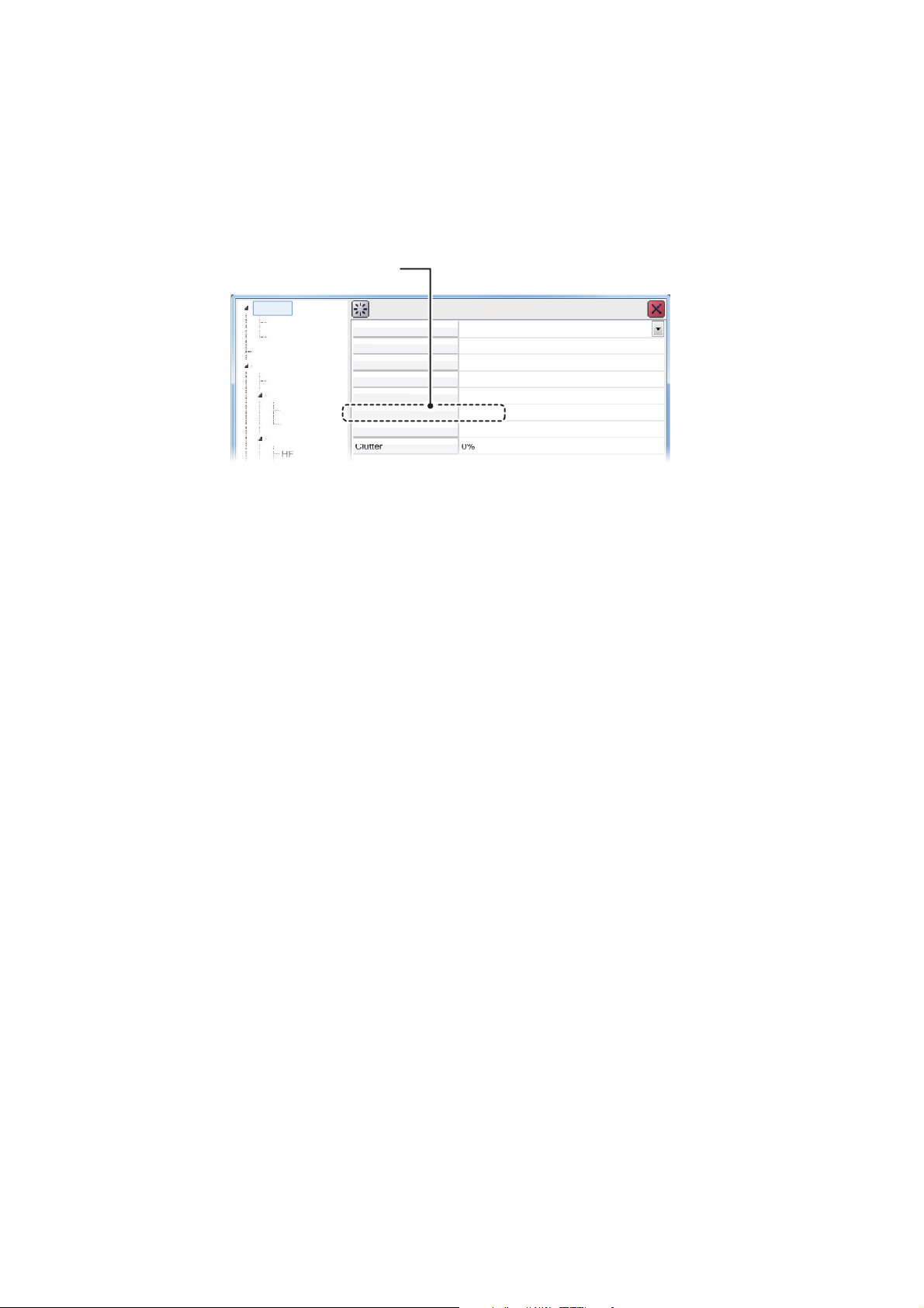
1. Place the cursor inside the external fish finder screen, then right-click. The [Exter-
nal Fish Finder] menu appears.
ounde
Syste
TX/RX
e
erence Rejectio
or Eras
r
. Advan
moo
ounde
n
2. The [Sounder] item is already selected. At the right-side of the menu window, se-
lect [Pic. Advance].
3. Select the drop-down options button at the far right-hand side of the screen.
4. Select the appropriate speed.
5. Select [Apply] to save the current changes and change or adjust other settings.
Select [OK] to save the current changes and close the menu window.
Select [Cancel] to abort all changes and close the menu window.
1-12
Page 25
1.6 How to Adjust the Gain
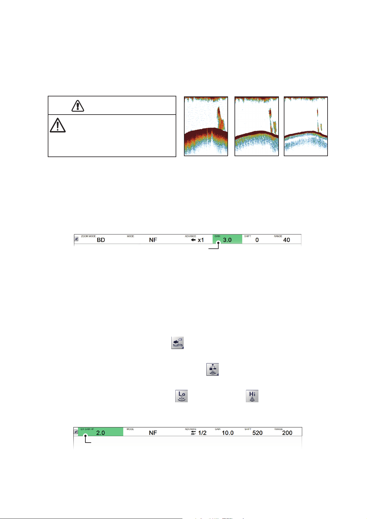
CAUTION
[
GAIN] indication
[
EX GAIN HF] indication.
For low frequency, this indication appears as [EX GAIN LF
].
Depending on the signal strength, gain can be adjusted to hide noise and other unnecessary echoes. A high gain setting increases signal strength and can show excessive noise as well as smaller, hard to detect echoes. A low gain setting eliminates
noise and gives a clearer picture, however smaller echoes may also be removed.
CAUTION
Adjust the gain properly.
Too little gain may present no picture.
Too much gain shows excessive
noise on the picture.
Too high
1.6.1 How to adjust the gain for the FCV-2100
1. Display the header if it is not “pinned”. If the header is already displayed, go to step
2.
Proper
1. OPERATION
Too low
2. Select the [GAIN] indication on the header. The indication is now highlighted in a
green color.
3. Scroll to change the amount of gain used. The current gain setting appears in on
the header.
The gain setting affects previous echoes as well as new echoes. This allows you
to adjust the gain to a “proper” level. A recommended gain level is where noise is
only just starting to appear on the display.
1.6.2 How to adjust the gain for external fish finders where [External
Fish Finder] is set to [Off] at installation
1. Select the [Sounder] icon ( ) from the InstantAccess bar™. The [Sounder]
menu appears.
2. Select the [External Fish Finder] icon ( ). The high/low frequency icons ap-
pear.
3. Select the appropriate icon, for low frequency, for high frequency. The
indication on the header changes to [EX GAIN LF] or [EX GAIN HF] respectively
and the indication changes to a green color.
4. Scroll to adjust the external fish finder’s gain.
1-13
Page 26
1. OPERATION
LF
S
m
Gain
TVG L
l
STC
0
5
0
S
r
LF
Display
External fish finder’s gain setting.
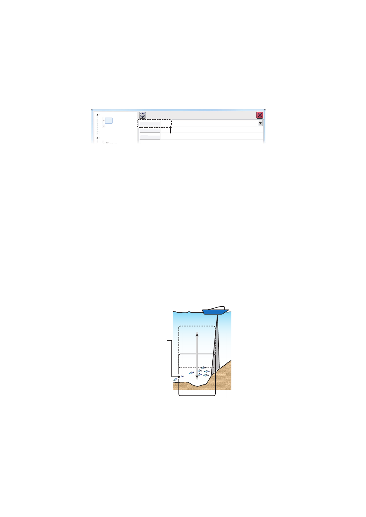
1.6.3 How to adjust the gain for external fish finders where [External
Fish Finder Window] is set to [On] at installation
1. Place the cursor inside the external fish finder screen, then right-click. The [Exter-
nal Fish Finder] menu appears.
2. The [Sounder] menu is already selected. Select the [HF] or [LF] item from the
[Sounder] menu. The settings for the external fish finder appear in the right-side
of the menu window.
ounde
2.
eve
yste
Note: The menu for [HF] and [LF] are the same, the example above shows [HF].
Where [LF] is selected, set the items in a similar manner to this procedure.
3. Select the [Gain] item from the settings. The setting value is now highlighted.
4. To the far right-hand side of the gain value, select the button to decrease the
gain, or select the button to increase the gain.
5. Select [Apply] to save the current changes and change or adjust other settings.
Select [OK] to save the current changes and close the menu window.
Select [Cancel] to abort all changes and close the menu window.
1.7 How to Shift the Display Range
When used together, the basic range and range shifting functions allow you to select
the depth you can see on the screen. The basic range can be thought of as providing
a “window” into the water column and range shifting as moving the “window” to the desired depth.
Window can be
shifted up and
down to select
starting depth.
Note 1: This function is not available when auto range or auto shift is active.
Note 2: The seabed echo may be lost if the shift is at a greater value than the seabed
depth.
1-14
Page 27
1. OPERATION
[
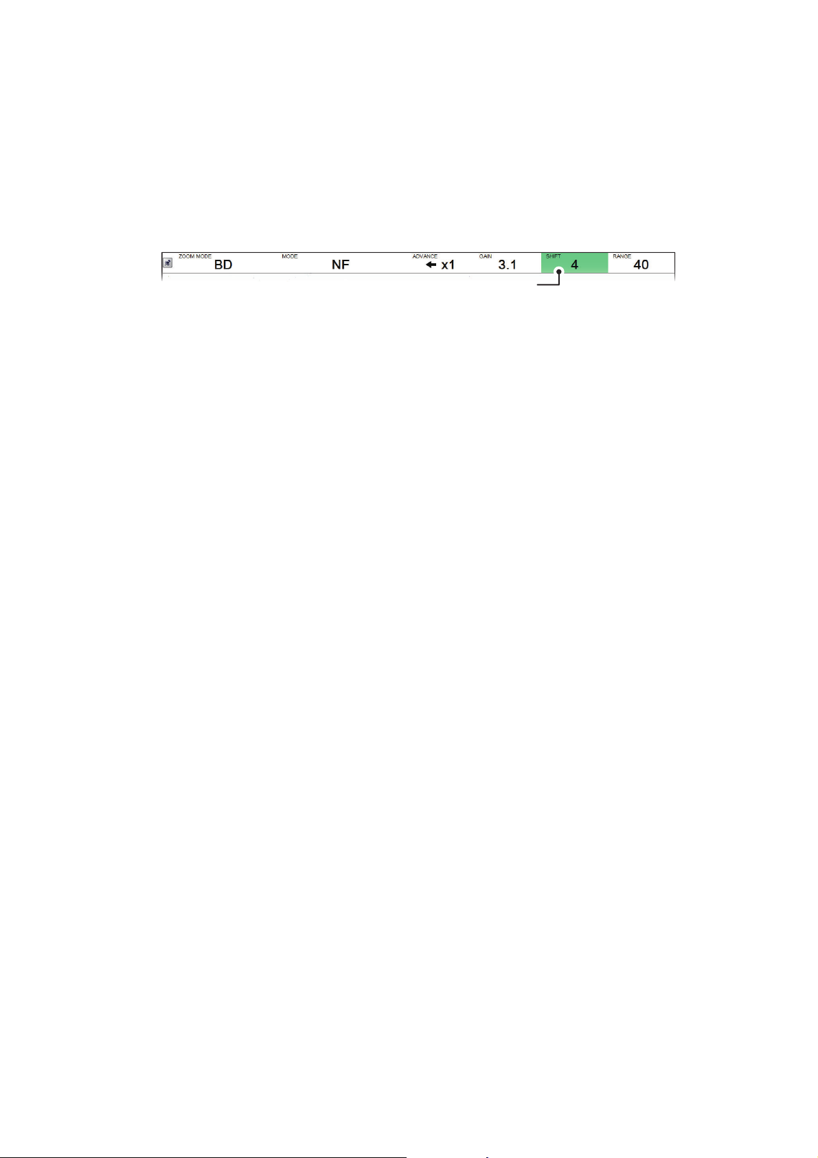
SHIFT] indication
1.7.1 How to shift the display range for the FCV-2100 and external fish finders
Where [External Fish Finder Window] is set to [Off] at installation, the shift function is
applied to both the FCV-2100 and the external fish finder.
1. Display the header if it is not “pinned”. If the header is displayed, go to step 2.
2. Select the [SHIFT] indication on the header. The indication is now highlighted in a
green color.
3. Scroll to change the amount of shift used. The current shift setting appears in on
the header.
1.7.2 How to shift the display range for external fish finders where [External Fish Finder Window] is set to [On] at installation
1. Place the cursor inside the external fish finder screen, then right-click. The [Exter-
nal Fish Finder] menu appears.
2. The [Sounder] item is already selected. At the right-side of the menu window, se-
lect [Shift].
3. To the far right-hand side of the [Shift] setting value, select the button to de-
crease the setting, or select the button to increase the setting.
4. Select [Apply] to save the current changes and change or adjust other settings.
Select [OK] to save the current changes and close the menu window.
Select [Cancel] to abort all changes and close the menu window.
1-15
Page 28
1. OPERATION
[
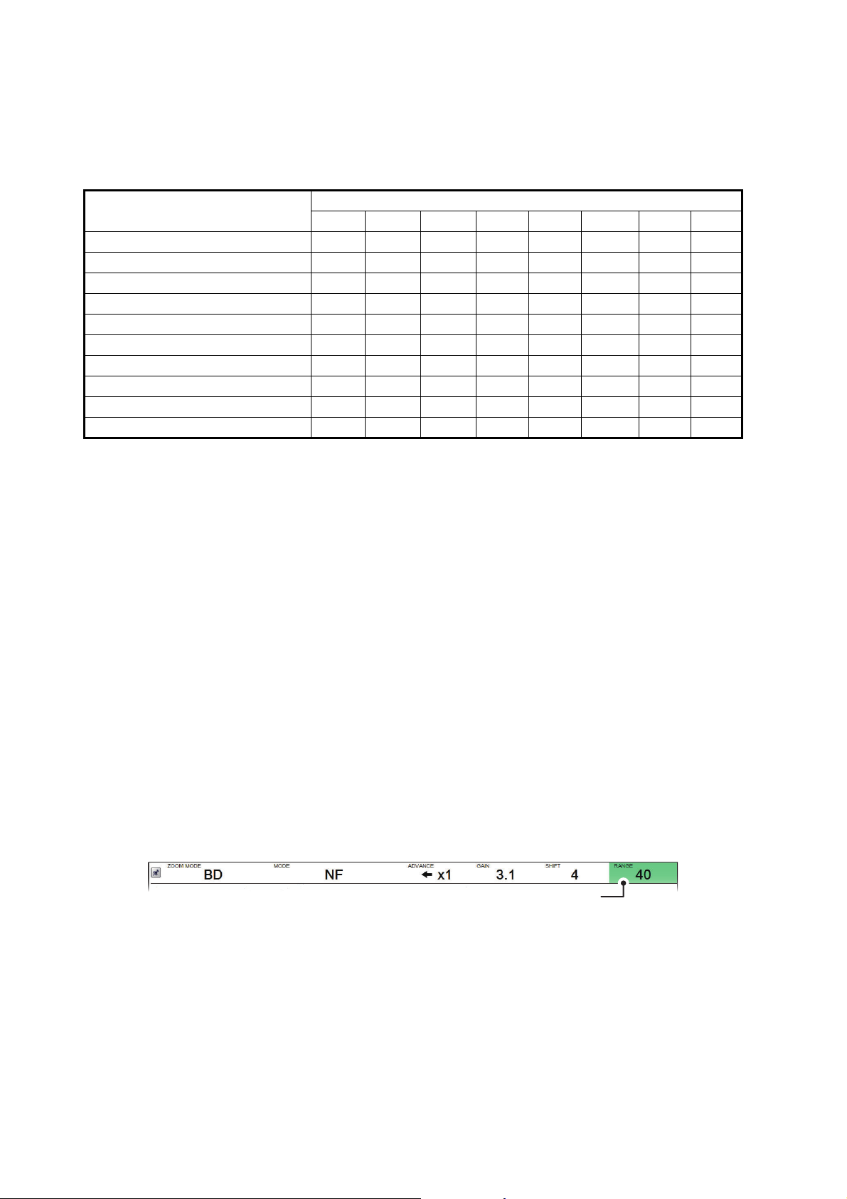
RANGE] indication
1.8 How to Change the Range
The range setting dictates the on-screen display distance and can be changed to suit
your requirements. The system has eight presets, each of which can be changed. The
default setting for the presets is listed in the table below.
Unit of measurement &
Connected fish finder
m (FCV-2100/DFF1-UHD) 10 20 40 80 150 300 500 800
m (DFF3 - On) 5 10 20 40 80 150 300 1500
ft (FCV-2100/DFF1-UHD) 30 60 100 250 450 900 1500 2500
ft (DFF3 - On) 15 30 60 120 200 400 1000 4500
fa (FCV-2100/DFF1-UHD) 5 10 20 40 75 150 250 400
fa (DFF3 - On) 3 5 10 20 40 80 150 900
Hiro* (FCV-2100/DFF1-UHD) 6 12 25 50 100 200 300 500
Hiro* (DFF3 - On) 4 8 15 30 50 100 200 1200
pb (FCV-2100/DFF1-UHD) 6 12 25 50 90 200 300 450
pb (DFF3 - On) 3 5 15 30 50 100 200 900
*: Japanese unit of depth measurement.
Note 1: The preset ranges for the DFF3 when [External Fish Finder Window] set to
[On] at installation are listed below as “DFF3 - On”. Where [External Fish Finder Window] set to [Off] at installation, the defaults are the same as FCV-2100 and DFF1UHD.
Note 2: You can change the preset range for of the presets, according to your requirements. See section 4.7.1 or section 4.8.4 for details.
12345678
Presets
1.8.1 How to change the range for FCV-2100 and external fish finders
Where [External Fish Finder Window] is set to [Off] at installation, the shift function is
applied to both the FCV-2100 and the external fish finder.
To change the range, do the following:
1. Display the header if it is not “pinned”. If the header is already displayed, go to step
2.
2. Select the [RANGE] indication on the header. The indication is now highlighted in
a green color.
3. Scroll to change the range. The display changes automatically with each change
in range.
Note 1: Where either auto shift or auto range is active, range cannot be adjusted manually.
1-16
Page 29
1. OPERATION
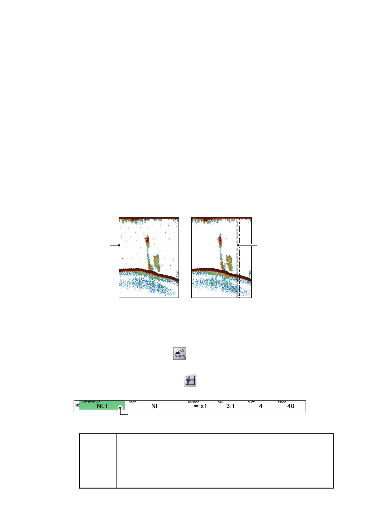
Interference from
other sounder
(blue dots)
Electrical interference
1.8.2 How to change the range for external fish finders where [External Fish Finder Window] is set to [On] at installation
1. Place the cursor inside the external fish finder screen, then right-click. The [Exter-
nal Fish Finder] menu appears.
2. The [Sounder] item is already selected. At the right-side of the menu window, se-
lect [Range].
3. Select the drop-down options button to show the preset range settings.
4. Select the appropriate range.
5. Select [Apply] to save the current changes and change or adjust other settings.
Select [OK] to save the current changes and close the menu window.
Select [Cancel] to abort all changes and close the menu window.
1.9 How to Reject Interference
Interference from other acoustic equipment operating nearby or other electronic
equipment on your boat may show itself on the display as shown in the figure below.
When this occurs use the interference rejector.
Note: A high setting for interference rejection can also remove weak echoes (small
targets).
1.9.1 Interference rejection for the FCV-2100
1. Select the [Sounder] icon ( ) from the InstantAccess bar™. The [Sounder]
menu appears.
2. Select the [Interference] icon ( ). [INTERFERENCE] appears in the miscella-
neous section of the header and is highlighted in a green color.
[
INTERFERENCE] indication
3. Scroll to adjust the level of interference rejection, referring to the table below.
Setting Description
[Off] Disable interference rejection.
[NL1] Low level of rejection.
[NL2] Medium level of rejection.
[NL3] High level of rejection.
[Auto] Automatically adjust the level of rejection to suit current conditions.
1-17
Page 30
1. OPERATION
S
S
r
Display
M
ent
I
O
0%
S
g
Clut
ter
Alarm
Soun
der
Soun
der
HF
LF
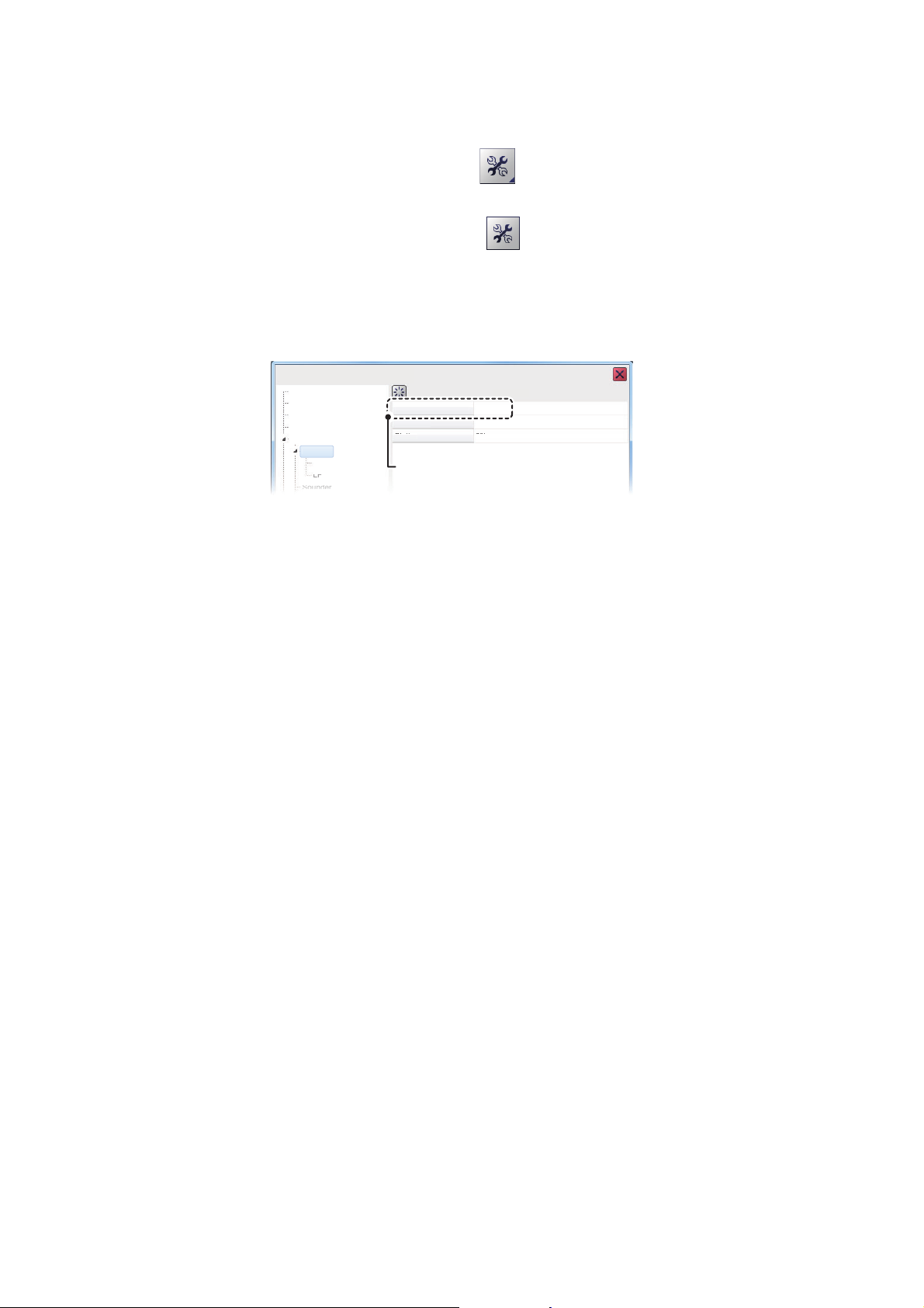
External fish finder’s
interference rejection setting.
FCV-2100 [ver 0252446-xx.xx]
1.9.2 Interference rejection for external fish finders where [External Fish Finder Window] is set to [Off] at installation
1. Select the [Advanced Settings] icon ( ) from the InstantAccess bar™. The [Ad-
vanced Settings] menu appears.
2. Select the [Advanced Settings] icon ( ) from the [Advanced Settings] menu.
The [Advanced Settings] window appears.
3. Select the [Sounder] item from the [External Fish Finder] menu, on the left-side of
the window. The external fish finder settings are shown on the right-side of the
window.
ounder
easurem
External Echo Sounder
nterference RejectionAuto
moothin
ounde
n
4. Select the [Interference] setting. The drop-down options box appears at the far
right-side of the window.
5. Select the drop-down box, then select the appropriate interference level, referring
to the table in section 1.9.1.
6. Select [Apply] to save the current changes and change or adjust other settings.
Select [OK] to save the current changes and close the menu window.
Select [Cancel] to abort all changes and close the menu window.
1.9.3 Interference rejection for external fish finders where [External
Fish Finder Window] is set to [On] at installation
1. Place the cursor inside the external fish finder screen, then right-click. The [Exter-
nal Fish Finder] menu appears.
2. The [Sounder] menu is already selected.
1-18
3. Select the [Interference] setting. The drop-down options box appears at the far
right-side of the window.
4. Select the drop-down box, then select the appropriate interference level, referring
to the table in section 1.9.1.
5. Select [Apply] to save the current changes and change or adjust other settings.
Select [OK] to save the current changes and close the menu window.
Select [Cancel] to abort all changes and close the menu window.
Page 31
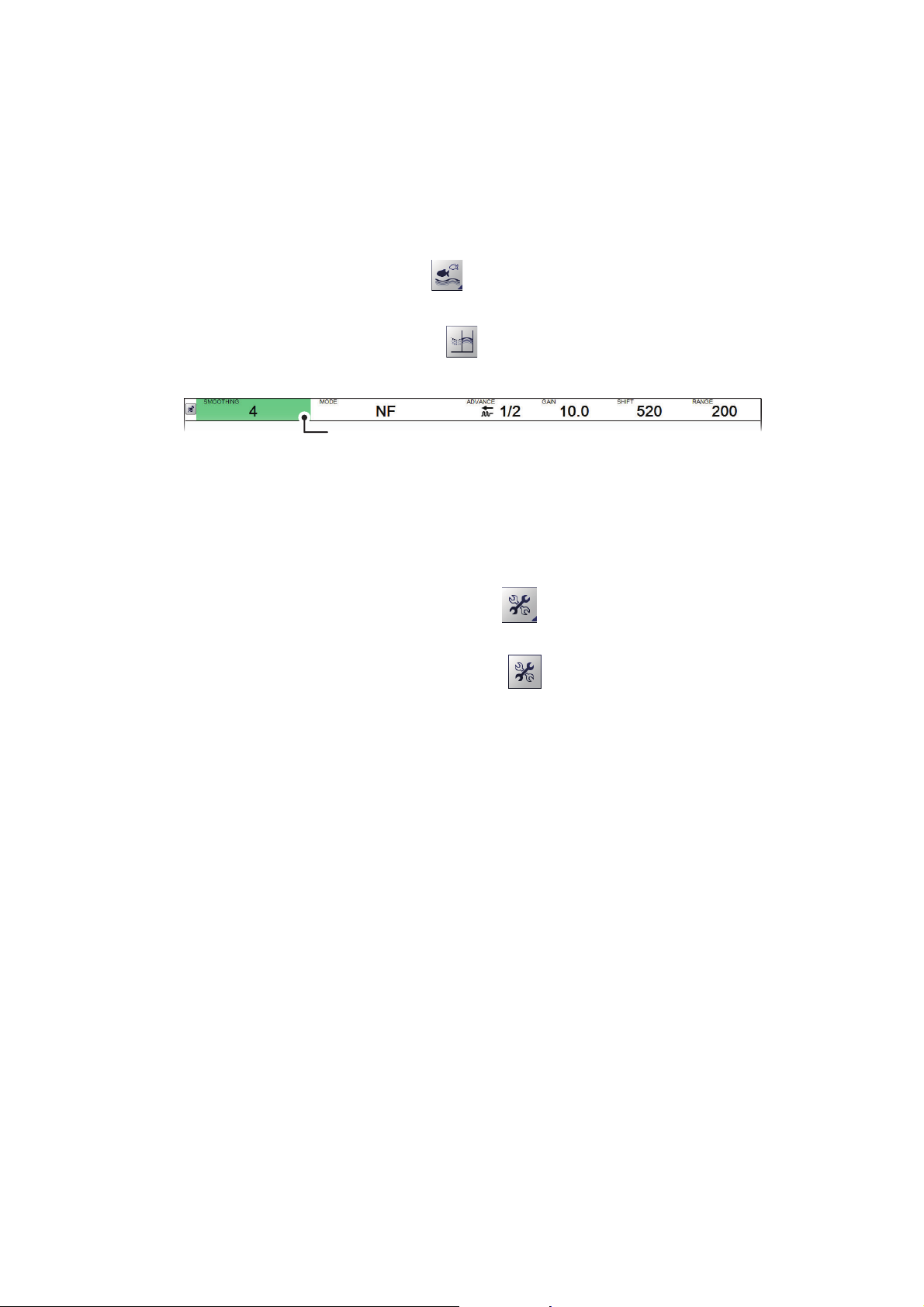
1.10 How to Use the Smoothing Function
[
SMOOTHING] indication
The smoothing function “smooths” echo presentation when enabled. This is particularly useful when echoes appear “spotty” or “jagged”. Smoothing can also be used to
reduce screen flicker at night.
1.10.1 How to use smoothing for the FCV-2100
1. Select the [Sounder] icon ( ) from the InstantAccess bar™. The [Sounder]
menu appears.
2. Select the [Smoothing] icon ( ). [SMOOTHING] appears in the miscellaneous
section of the header and is highlighted in a green color.
3. Scroll to adjust the level of smoothing. A high value increases the amount of
smoothing applied to the picture.
1. OPERATION
1.10.2 How to use smoothing for external fish finders where [External Fish Finder Window] is set to [Off] at installation
1. Select the [Advanced Settings] icon ( ) from the InstantAccess bar™. The [Ad-
vanced Settings] menu appears.
2. Select the [Advanced Settings] icon ( ) from the [Advanced Settings] menu.
The [Advanced Settings] window appears.
3. Select the [Sounder] item from the [External Fish Finder] menu, on the left-side of
the window. The external fish finder settings are shown on the right-side of the
window.
4. Select the [Smoothing] setting. The drop-down options box appears at the far
right-side of the window.
5. Select the drop-down box, then select the appropriate smoothing level. A high val-
ue increases the amount of smoothing applied to the picture.
6. Select [Apply] to save the current changes and change or adjust other settings.
Select [OK] to save the current changes and close the menu window.
Select [Cancel] to abort all changes and close the menu window.
1-19
Page 32
1. OPERATION
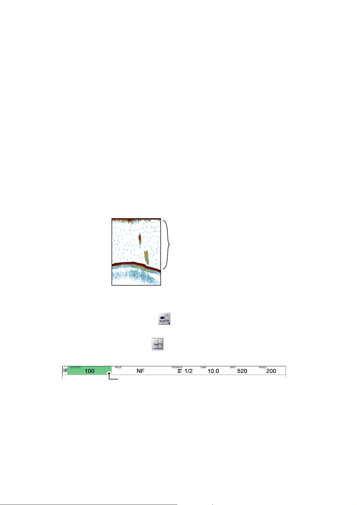
Low level noise (clutter)
appears as “speckles”
on the display.
[
CLUTTER] indication
1.10.3 How to use smoothing for external fish finders where [External
Fish Finder Window] is set to [On] at installation
1. Place the cursor inside the external fish finder screen, then right-click. The [Exter-
nal Fish Finder] menu appears.
2. The [Sounder] menu is already selected.
3. Select the [Smoothing] setting. The drop-down options box appears at the far
right-side of the window.
4. Select the drop-down box, then select the appropriate smoothing level. A high val-
ue increases the amount of smoothing applied to the picture.
5. Select [Apply] to save the current changes and change or adjust other settings.
Select [OK] to save the current changes and close the menu window.
Select [Cancel] to abort all changes and close the menu window.
1.11 How to Reject Low Level Noise (Clutter)
Low intensity “speckles” are referred to as clutter, and can appear over most of the
screen. Clutter is often caused by sediment in the water or noise. These unwanted
echoes can be rejected.
1.11.1 How to reject clutter for the FCV-2100
1. Select the [Sounder] icon ( ) from the InstantAccess bar™. The [Sounder]
menu appears.
2. Select the [Clutter] icon ( ). [CLUTTER] appears in the miscellaneous section
of the header and is highlighted in a green color.
3. Scroll to adjust the level of noise rejection. A high value setting reduces more
noise, but can also remove weak echoes (small targets).
1-20
Page 33

1. OPERATION
1.11.2 How to reject clutter for external fish finders where [External Fish Finder Window] is set to [Off] at installation
1. Select the [Advanced Settings] icon ( ) from the InstantAccess bar™. The [Ad-
vanced Settings] menu appears.
2. Select the [Advanced Settings] icon ( ) from the [Advanced Settings] menu.
The [Advanced Settings] window appears.
3. Select the [Sounder] item from the [External Fish Finder] menu, on the left-side of
the window. The external fish finder settings are shown on the right-side of the
window.
4. Select the [Clutter] setting. The drop-down options box appears at the far right-
side of the window.
5. Select the drop-down box, then select the appropriate noise reduction level. A
high value setting reduces more noise, but can also remove weak echoes (small
targets).
6. Select [Apply] to save the current changes and change or adjust other settings.
Select [OK] to save the current changes and close the menu window.
Select [Cancel] to abort all changes and close the menu window.
1.11.3 How to reject clutter for external fish finders where [External Fish Finder Window] is set to [On] at installation
1. Place the cursor inside the external fish finder screen, then right-click. The [Exter-
nal Fish Finder] menu appears.
2. The [Sounder] menu is already selected.
3. Select the [Clutter] setting ([40%] in the example figure above). The drop-down
options box appears at the far right-side of the window.
4. Select the drop-down box, then select the appropriate noise reduction level. A
high value setting reduces more noise, but can also remove weak echoes (small
targets).
5. Select [Apply] to save the current changes and change or adjust other settings.
Select [OK] to save the current changes and close the menu window.
Select [Cancel] to abort all changes and close the menu window.
1-21
Page 34
1. OPERATION
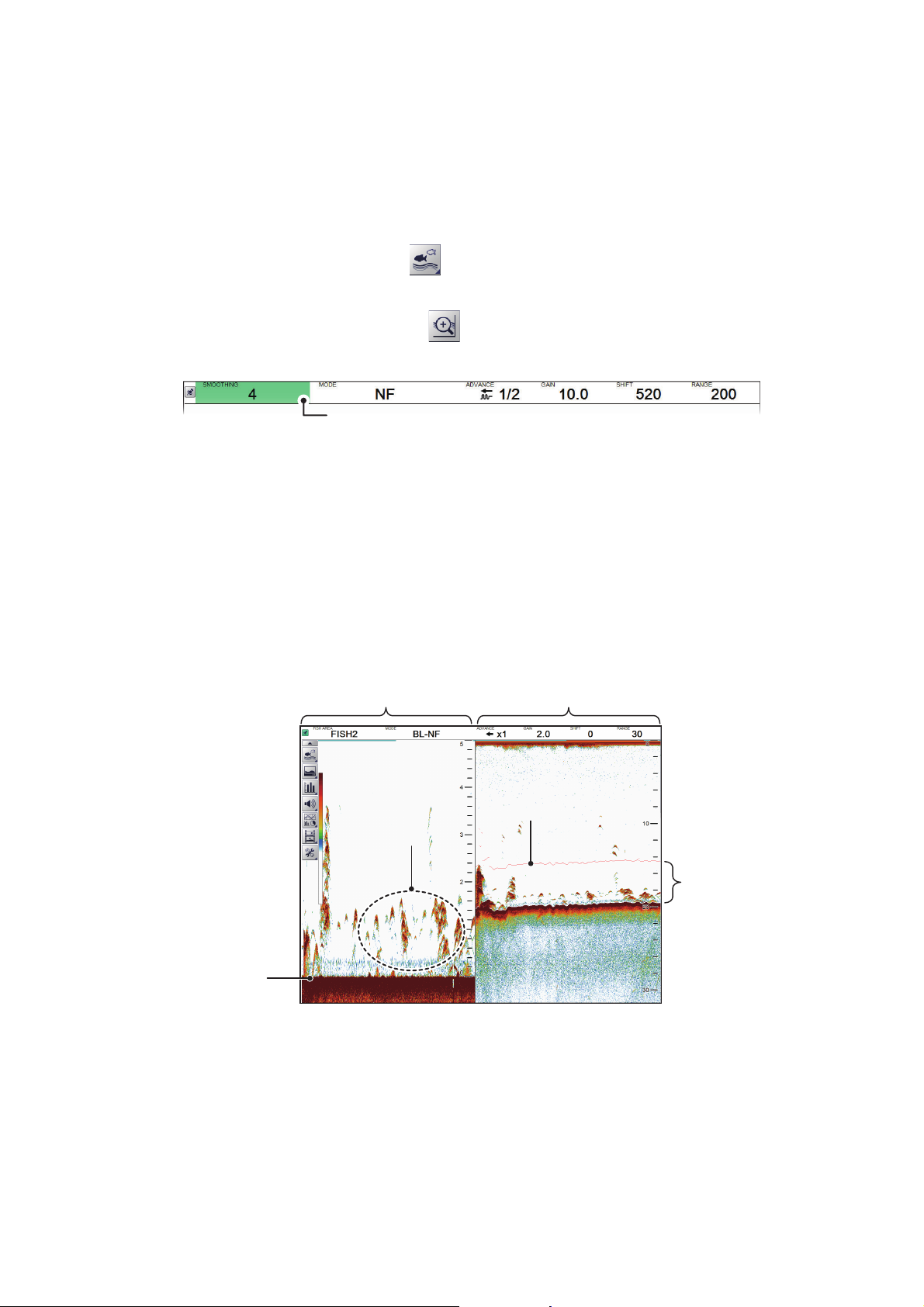
[
SMOOTHING] indication
Zoom marker
Zoomed echoes
Smoothed seabed
This area
is zoomed.
Bottom lock zoom
mode displayed
Un-zoomed single
frequency displayed
1.12 Zoom Display
The zoom displays expand the specified area of the single frequency echo. Four
modes are available: bottom lock, bottom zoom, marker zoom and bottom discrimination. The default mode is bottom lock.
To select a zoom mode, do the following:
1. Select the [Sounder] icon ( ) from the InstantAccess bar™. The [Sounder]
menu appears.
2. Select the [Zoom] mode icon ( ). [ZOOM MODE] appears in the miscellaneous
section of the header.
3. Scroll to show the desired zoom mode. The four modes are shown in abbreviated
format, see the list below for reference.
• BL: Bottom lock
• BZ: Bottom zoom
• MZ: Marker zoom
• BD: Bottom discrimination
1.12.1 Bottom lock mode
Bottom lock mode provides a normal picture on the right-side of the screen and a magnified picture on the left-side of the screen. The zoomed area shows a smooth seabed,
making it easier to detect fish near the seabed.
1-22
Note 1: The range for the zoom display can be adjusted from the [Range] menu. See
section 4.7.1.
Note 2: To show or hide the zoom marker, change the setting for [Zoom Marker] in the
[Display] menu. See section 4.3.
Page 35
1.12.2 Bottom zoom mode
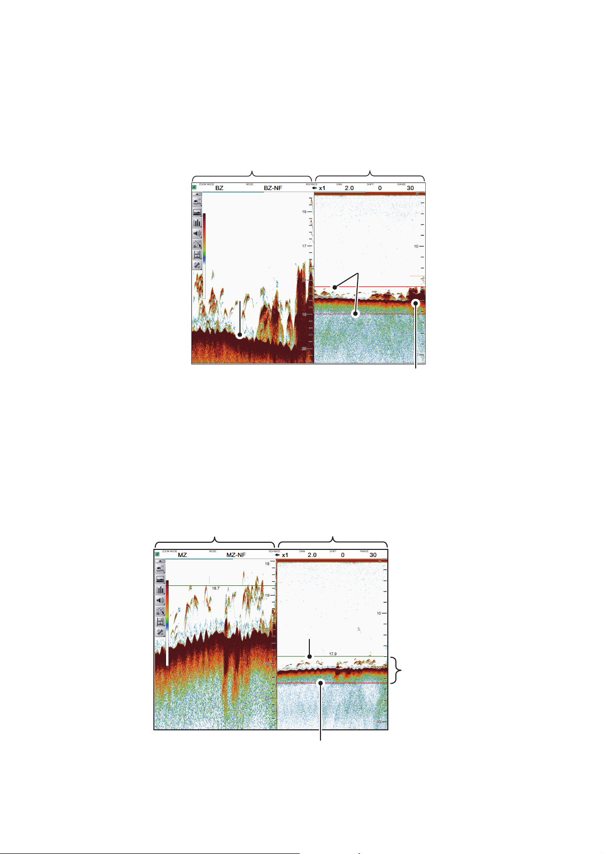
Bottom zoom
mode displayed
Un-zoomed single
frequency displayed
Zoom area automatically follows the
seabed when the depth changes.
Zoom markers
Seabed echoSeabed echo
Marker zoom
area displayed
Zoomed area
Zoom marker
Un-zoomed single
frequency displayed
VRM
This mode magnifies the seabed, and also any fish near the seabed, on the left-side
of the screen, and is useful for determining seabed contours. When the seabed depth
increases, the display automatically shifts to keep the seabed echo at the lower part
of the screen.
1. OPERATION
1.12.3 Marker zoom mode
The marker zoom mode magnifies the specified area of the normal picture to full vertical size of the screen on the left-side of the screen. You may specify the portion to
expand by operating the VRM (Variable Range Marker). The area between the VRM
and zoom marker is expanded. This mode is useful for determining the size of fish in
the midwater.
1-23
Page 36
1. OPERATION
[
Bottom discrimination 1/2]
displayed
Un-zoomed single
frequency displayed
Seabed echo tails.
Long tails indicates a hard
seabed (Rock, gravel, etc.)
Short tails indicates a soft
seabed (Mud, sand, etc.)
[
Bottom discrimination 1/3]
displayed
Un-zoomed single
frequency displayed
Seabed echo tails.
Long tails indicates a hard
seabed (Rock, gravel, etc.)
Short tails indicates a soft
seabed (Mud, sand, etc.)
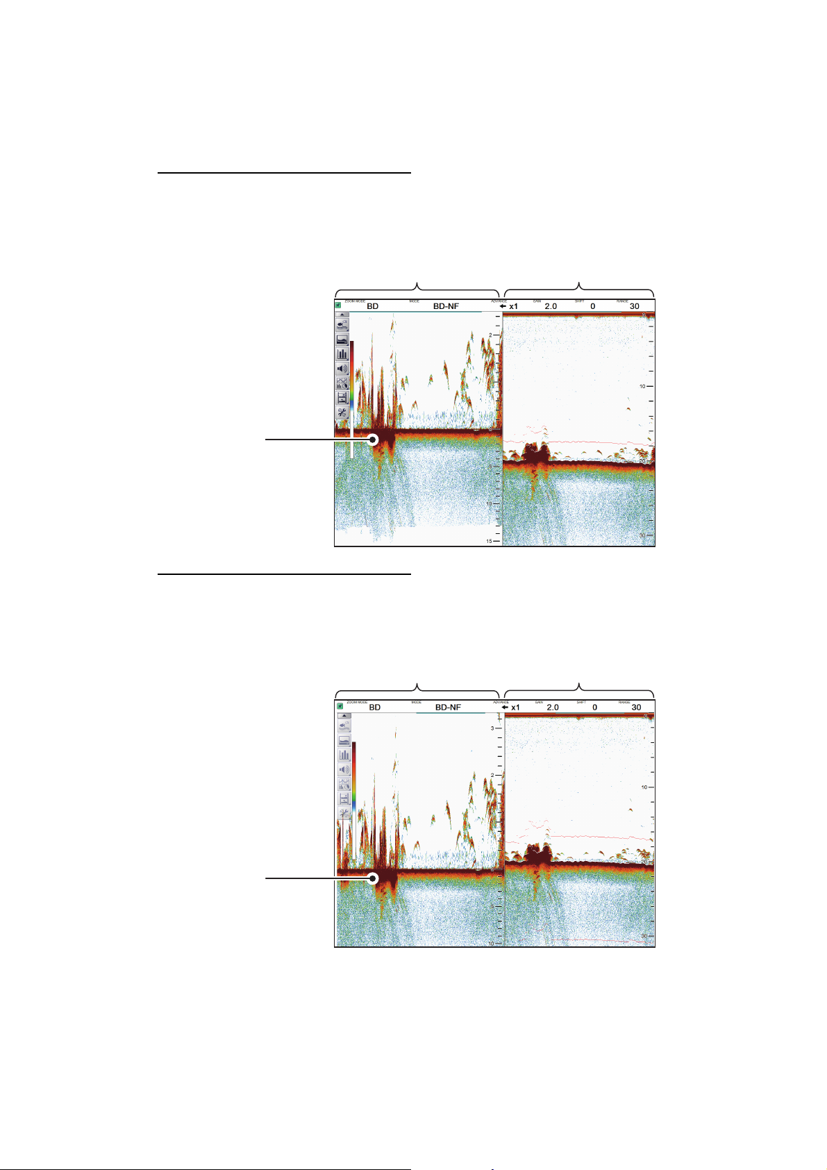
1.12.4 Bottom discrimination mode
Bottom discrimination mode has two zoom ratios which can be set from the [Range]
section of the [System] menu. See section 4.7.1 for details.
Bottom discrimination at 1/2 ratio
The left-side of the screen show the seabed as a straight line at approximately the
middle of the screen.
Bottom discrimination at 1/3 ratio
The left-side of the screen show the seabed as a straight line at approximately one
third of the screen-length from the screen bottom.
1-24
Page 37
1. OPERATION
Day mode Night mode
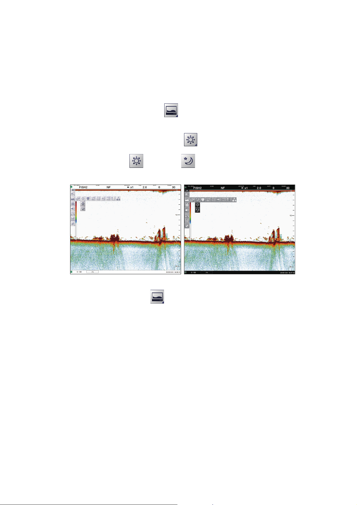
1.13 How to Switch Between Display Color Modes
To assist on-screen visibility, the system has a Day display color mode and a Night
display mode. The modes can be changed at any time from the InstantAccess bar™
to suit your needs.
Unless otherwise specified, all example figures in this manual use the Day display
mode.
1. Select the [Display] icon ( ) from the InstantAccess bar™. The [Display]
menu bar appears.
2. Select the [Window Color] icon ( ). The menu options appear.
3. Select [Day] ( ) or [Night] ( ) as appropriate. Icon and text color is re-
versed, as shown in the example figures below.
4. Select the [Display] ( ) icon to hide the menu bar.
1-25
Page 38
1. OPERATION
Weak echoes (small fish school or noise)
Fish school echo
Strong echo (seabed)
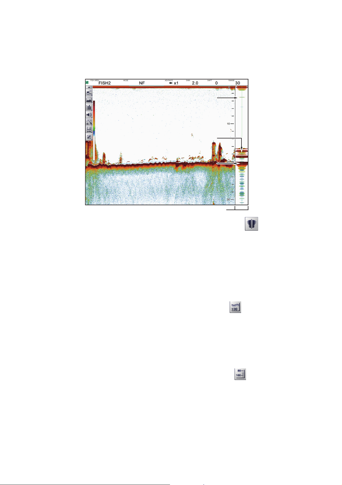
1.14 How to Use the A-Scope Display
The A-Scope display shows echoes at each transmission with amplitudes and tone
proportional to their intensities, on the right side of the screen. It is useful for estimating
the species of a school of fish or determining bottom composition.
Weak echoes (small fish school or noise)
Fish school echo
Strong echo (seabed)
A-Scope display
To show or hide the A-Scope display, select the [A-Scope] icon ( ) from the [Dis-
play] menu, on the InstantAccess bar™. The icon changes to green color when
shown.
1.15 How To Show/Hide The Depth Indication
The current depth indication appears at the bottom-left of the screen. You can show
or hide the depth indication to suit your preferences.
To show/hide the depth indication, select the [Depth] icon ( ) from the [Display]
menu on the InstantAccess bar™. The icon changes to green color when shown.
1.16 How To Show/Hide The Depth Scale
The depth scale is displayed to the far right-hand side of the screen.
To show/hide the depth scale, select the [Depth Scale] icon ( ) from the [Display]
1-26
menu on the InstantAccess bar™. The icon changes to green color when shown.
Page 39
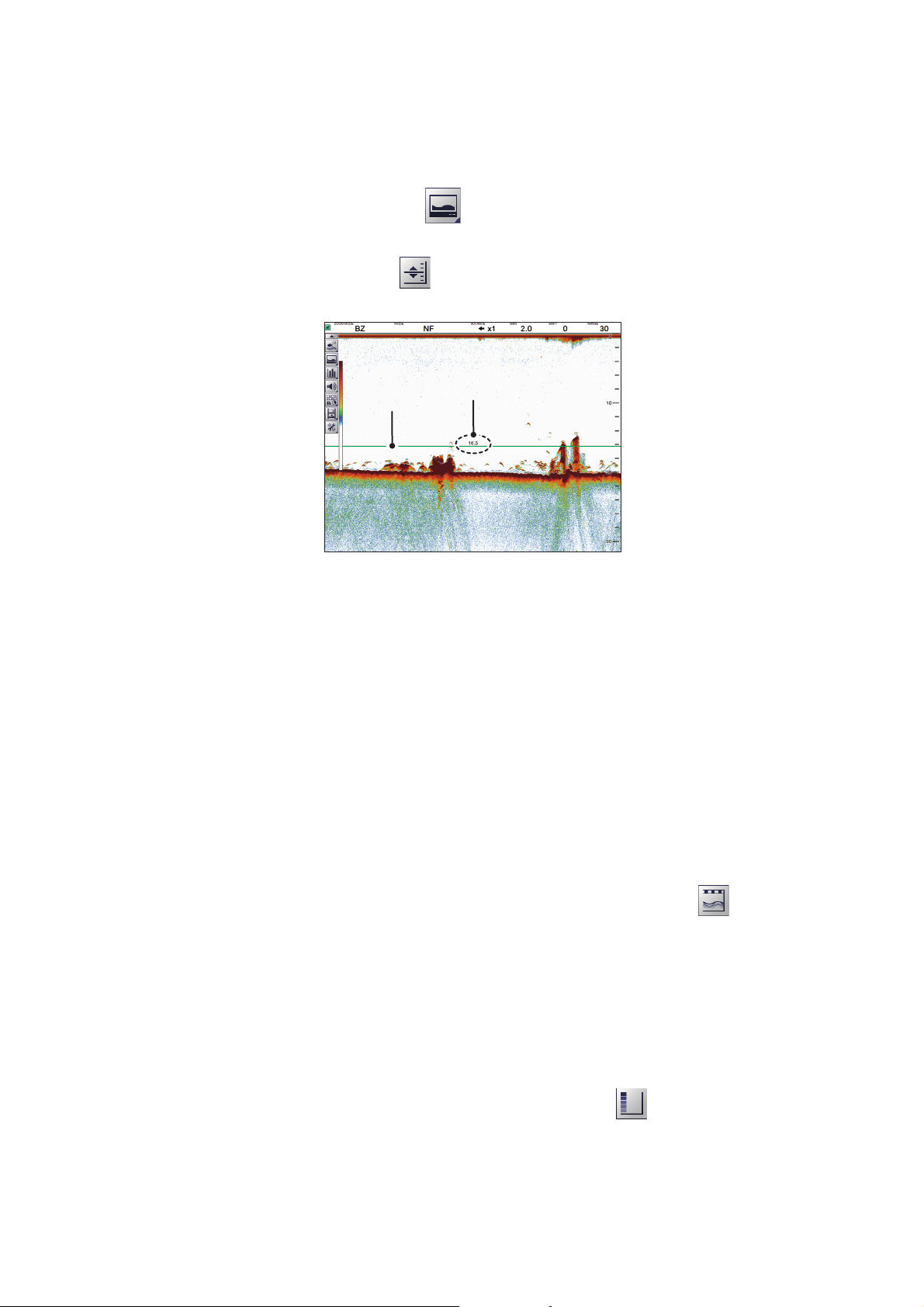
1.17 How to Measure Depth
VRM depth
VRM
You can measure depth at any time with the VRM (Variable Range Marker), making
fish and fish schools easier to target.
1. Select the [Display] icon ( ) from the InstantAccess bar™. The [Display]
menu appears.
2. Select the [VRM] icon ( ). The [VRM] icon is now highlighted in green color and
the VRM appears on the display.
1. OPERATION
3. Drag and drop the VRM so that it intersects the echo who’s depth you want to
measure. The depth is displayed above (or below) the VRM, at the center of the
VRM.
To hide the VRM, repeat steps 1 and 2, in order.
Note: When MZ (Marker Zoom) is selected as a display mode, the VRM is constantly
displayed, regardless of VRM settings.
1.18 How To Show/Hide The Minute Marker
The Minute Marker appears at the top of the screen when displayed. It is displayed as
a dashed line, with each dash, and gap between dashes, indicating a 30 second period of time. In other words, the time from the start of one dash to the start of the next
dash is one minute.
To show/hide the time interval line, select the [Minute Marker] icon ( ) from the Dis-
play menu on the InstantAccess bar™. The icon changes to green color when shown.
1.19 How To Show/Hide The Color Bar
The color bar shows the echo color scale in use, with the strongest echo color at the
top of the scale and weakest echo color at the bottom.
To show/hide the color bar, select the [Color Bar] icon ( ) from the Display menu
on the InstantAccess bar™. The icon changes to green color when shown.
1-27
Page 40
1. OPERATION
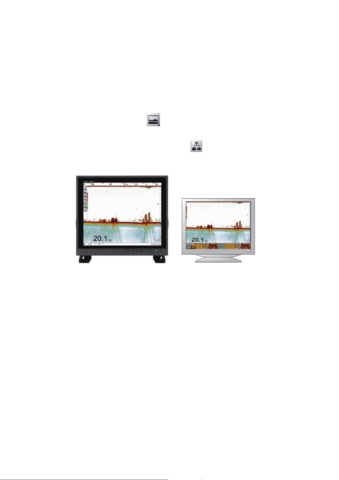
1.20 External Fish Finder Display
You can view an external fish finder’s echoes on a sub display if your system configuration meets the following requirements:
• Two monitors (main and sub-monitor) connected.
• External fish finder is connected to the FCV-2100.
• [External Fish Finder Window] is set to [On] at installation.
To show the external fish finder echoes on the sub display, do the following:
1. Select the [Display] icon ( ) from InstantAccess bar™. The Display menu ap-
pears.
2. Select the [External Echo Sounder] icon ( ). The sub monitor displays the ex-
ternal fish finder’s echoes. Further, the [External Echo Sounder] icon changes to
a green color.
Main monitor: Echoes from
FCV-2100 fish finder displayed.
Note: When the external fish finder display is active, settings changes and adjustments made to the FCV-2100 display are not reflected on the external display (with
the exception of language and units of measurement). Settings changes and adjustments for the external fish finder must be done from the sub monitor. Place the cursor
inside the external fish finder screen, then right-click to display the external fish finder
menu. (See section 4.8 for details.)
Sub monitor: Echoes from
external fish finder displayed.
1-28
Page 41
1. OPERATION
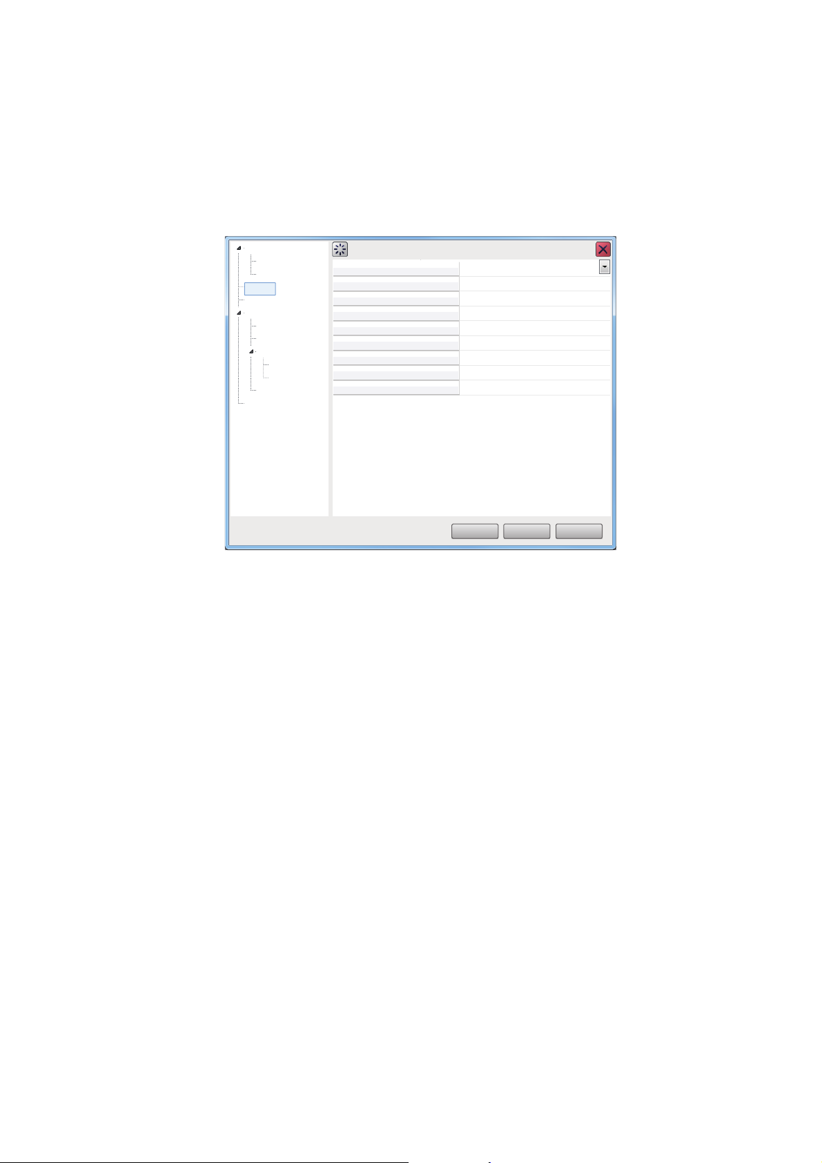
1.20.1 How to change the display mode on the external fish finder screen
You can change the display mode on an external monitor by doing the following:
1. Place the cursor inside the external fish finder screen, then right-click. The [Exter-
nal Fish Finder] menu appears.
2. Select [Display].
Sounder
HF
LF
Display
Measurement
System
Range
TX/RX
Calibration
HF
LF
Stabilization
Service
Mode
Display Division
Colors
Hue
Background
Depth Size
Depth Scale
Bottom Discrim
Bottom Discrimination Legend
Display
LF/HF
Vertical
64
Normal
White
Normal
Right
Probability
Off
OK
Apply
Cancel
3. Select the drop-down icon for the [Mode] setting, on the right-side of the menu.
The drop-down options appear.
4. Select the appropriate option:
[LF/HF] : High and low frequency images.
[HF] : High frequency images only.
[LF] : Low frequency images only.
5. If you select [LF] or [HF] at step 4, go to the step 6.
If you selected [HF/LF] at step 4, set the screen division from the [Display Division]
menu item, directly below the Mode menu item.
6. Select [Apply] to apply the changes and delete or edit a different mode. Select
[OK] to apply the changes and close the menu. Select [Cancel] to cancel any
changes made and close the menu.
1-29
Page 42
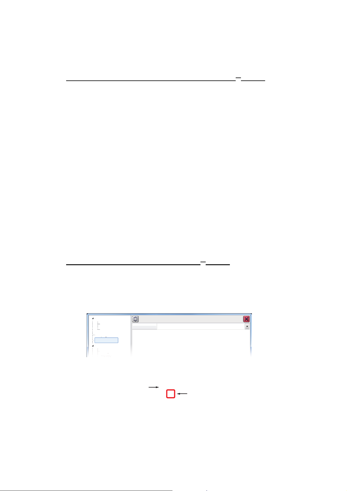
1. OPERATION
1.20.2 How to use the ACCU-FISH
The ACCU-FISH™ feature requires connection to a compatible transducer.
™
feature
The ACCU-FISH
™
feature outputs fish echoes with a mark and an estimated size.
Important considerations when using the ACCU-FISH™ feature
• The ACCU-FISH™ feature is intended for reference purposes; it is not a completely
accurate measurement of fish length.
• Echo intensity depends on fish species. When the fish length differs between the
indicated length and the actual length, you can compensate the difference on the
[Calibration] menu (see section 4.8.4).
• Fish at depths of less than two meters cannot be measured. However, if [Zero Line
Rejector] is set to [On], fish within the area covered by the transmission line cannot
be detected.
• The maximum depth at which the ACCU-FISH
™
feature can detect fish varies, depending on transducer type, vessel configuration, sea conditions and other factors
which may affect beam accuracy.
• In a school of fish, the echoes overlap. This causes a greater margin of error in fish
size measurement.
• This feature cannot be used with inside-hull transducers. Depending on the transducer frequency, fish may not be detected. Further, even if fish are detected, their
indicated length may be smaller than the actual length.
• The TX pulse length changes according to ACCU-FISH
™
On/Off state. This causes
a difference in both sensitivity and the echoes viewed.
How to activate/deactivate the ACCU-FISH™ feature
1. Place the cursor inside the external fish finder screen, then right-click. The [Exter-
nal Fish Finder] menu appears.
™
2. Select [Measurement]. The ACCU-FISH
setting appears in the right-side of the
window.
Sounder
HF
LF
Display
Measurement
System
Range
ACCU-FISH Off
Measurement
3. Select the drop-down box to the far right-hand side of the menu, then select [On].
ACCU-FISH
4. To deactivate ACCU-FISH
™
is now active, fish marks and sizes now appear on the screen.
Fish size
64
Fish mark
™
, repeat the procedure, then select [Off] at step 3.
1-30
Page 43
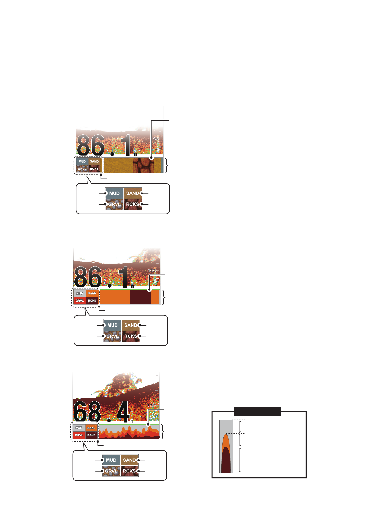
1. OPERATION
Hardness legend
Rock
Gravel
SandMud
Bottom
discrimination
display column
Probability bar: Appears above the bottom
discrimintation display and indicates the
degree of reliability for the bottom discrimination
display (Green, Normal; Yellow, Caution;
Background color, Abnormal)
Bottom
discrimination
display column
Probability bar
Hardness legend
Rock
Gravel
SandMud
1.20.3 How to display seabed composition (bottom discrimination)
The bottom discrimination display analyzes the seabed echo to categorize hardness
in one of four types (rocks, gravel, sand, mud), then shows the results in a colorful
graphic display. This function requires connection to a DFF1-UHD (or a transducer
compatible with bottom discrimination) and has the following three display formats:
• Graphic display: The most probable seabed composition (mud, sand, gravel, rock)
is indicated graphically.
• Four colors display: The most probable seabed composition (mud, sand, gravel,
rock) is indicated with four colors.
• Probability display: The most probable seabed composition is indicated in proportion.
Gravel
Probability bar
Hardness legend
SandMud
Rock
Bottom
discrimination
display column
Graph example
Mud probability
(Approx. 25%)
Sand probability
(Approx. 25%)
Rock probability
(Approx. 50%)
1-31
Page 44
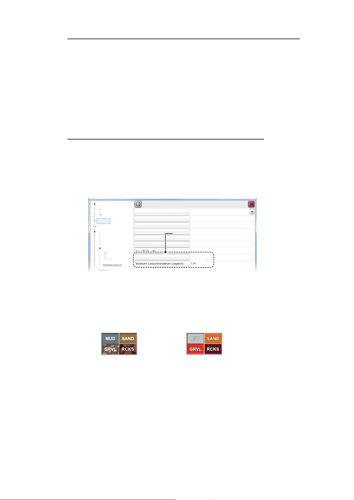
1. OPERATION
Mode
Displ
Col
H
Back
d
Depth Size
Depth Scale
Bot
tomDiscr
im
F
V
l
64
N
l
Whi
N
l
Righ
Pro
bab
ili
ty
y
Bot
tomDiscr
imi
nat
ionLegengd
Off
Display
HF
LF
HF
LF
S
m
Range
TX/
RX
C
on
Sta
bil
iza
tio
n
Ser
vic
e
S
Display
M
Bottom discrimination settingsBottom discrimination settings
Important considerations when using the bottom discrimination display
• The bottom discrimination display provides an estimate of seabed composition. Ac-
• Operating environment:
• This feature uses the range from the ship’s draft; therefore, enter the ship’s draft
• Be sure that the transducer is mounted straight. Otherwise the bottom discrimina-
How to activate/deactivate the bottom discrimination display
Note: Range and shift functions for the external fish finder are disabled when bottom
discrimination is active.
1. Place the cursor inside the external fish finder screen, then right-click. The [Exter-
2. Select [Display]. The Display setting appear in the right-side of the window.
tual composition may be different.
- Depth: 5 to 100 m (16 to 328 ft)
- Speed: 10 kn or less
(see section 4.7.5).
tion display may not function accurately.
nal Fish Finder] menu appears.
ounder
LF/H
ertica
orma
te
orma
t
easurement
yste
alibrati
ay Division
ors
ue
groun
3. Select the [Bottom Discrimination] setting.
4. Select the drop-down box to the far right-hand side of the menu, then select the
appropriate display format. Select [Off] to deactivate this function.
5. Select the [Bottom Discrimination Legend] setting.
6. Select [On] to show the legend, select [Off] to hide the legend.
[
Graphic] legend
[
4 Colors] and [Possibility] legend
7. Select [Apply] to apply the changes and delete or edit a different mode. Select
[OK] to apply the changes and close the menu. Select [Cancel] to cancel any
changes made and close the menu.
1-32
Page 45
1.21 How to Set, Show and Hide Alarms
: Bottom Alarm icon : Bottom Fish Alarm icon : Fish Size Alarm icon
: Temperature Alarm icon: Fish Alarm icon
The FCV-2100 has five alarms (Bottom Alarm, Fish Alarm, Bottom Fish Alarm, Temperature Alarm and Fish Size Alarm) and one Combined Alarm.
When an alarm is set and the conditions meet the alarm requirements, the system releases an audible beep and displays the corresponding alarm message alarm icon.
For combined alarms, all corresponding alarms messages and alarm icons are displayed.
To silence the audible beep, select the [OK] button on the alarm message. The alarm
icon remains visible on the display until the cause of the alarm is removed.
Alarm descriptions
• Bottom Alarm: Alerts you when the seabed (bottom) enters the range set for this
alarm.
1. OPERATION
• Fish Alarm: Alerts you when fish are detected within the range set for this alarm.
• Bottom Fish Alarm: Alerts you when fish are detected within the range set for this
alarm.
• Temperature Alarm: Alerts you when the water temperature is within range or out
of range, depending on your selection. This alarm requires connection to a temperature sensor.
• Fish Size Alarm: Alerts you when a fish detected meet or exceed the size and/or
distribution set for this alarm.
• Combined Alarm: This alarm is a combination of two or more of the above alarms.
When the requirements for all selected alarms are met, this alarm is triggered.
When this alarm is selected, individual alarms are not available.
1-33
Page 46
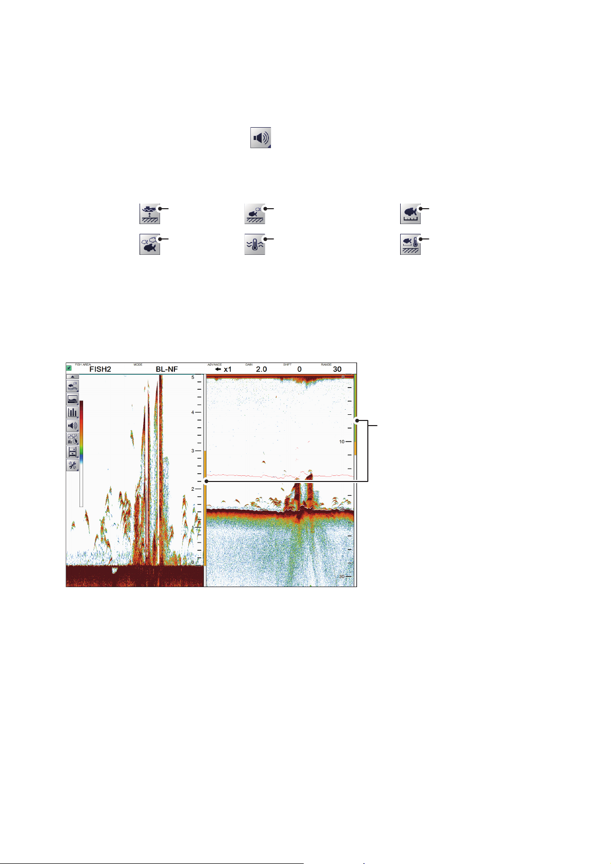
1. OPERATION
Bottom Alarm
Fish Alarm
Bottom fish Alarm
Water Temperature Alarm
Fish Size Graph Alarm
Combined Alarm
*
*: Requires connection to a temperature sensor.
Alarm markers, displayed in the
following colors:
Bottom Alarm: Green
Fish Alarm: Orange
Bottom Fish Alarm: Orange;
appears at the right-hand side of
the Bottom Lock or Bottom
Discrim Zoom screen only.
1.21.1 How to activate/deactivate the alarms
You can activate and deactivate alarms by selecting the respective alarm icon.
To activate or deactivate an alarm, do the following:
1. Select the Alarm icon ( ) from the InstantAccess bar™. The [Alarm] menu ap-
pears.
2. Referring to the figure below, select the alarm you want to activate or deactivate.
The icon changes color depending on whether the status selected.
• Green: Alarm is active.
• Gray: Alarm is not active.
The Bottom Alarm, Bottom Fish Alarm and Fish Alarm also show an “alarm marker”
on the right-side of the display. The alarm marker shows the alarm range.
Note: When the [Combined Alarm] is active, individual alarms are not available. To
activate alarms other than those included in the [Combined Alarm], do the following:
• Deactivate the [Combined Alarm], then activate the alarm(s) individually.
1-34
Page 47
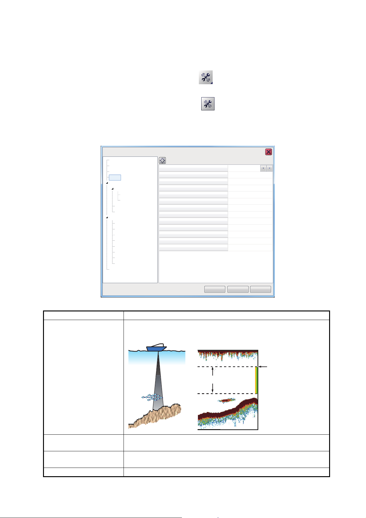
1.21.2 How to set the alarms
Sounder
Alarm
Bottom Start Depth
Bottom Depth Range
Fish Start Depth
Fish Depth Range
Bottom Fish Start Depth
Bottom Fish Depth Range
Temperature Alarm Trigger Temperatur
Fish Level
Medium
110.0
Temperature
Water Temperature Range
Fish Size Graph
Fish Graph Scale Threshold
Combined Alarm
2500
30
0
2500
600.0
0.1
In range
55.0
30%
Sounder
HF
LF
Display
Measurement
External Echo Sounder
Alarm
System
Range
TX/RX
TX/RX
Control Unit
Calibration
Calibration
Stabilization
Mode
Tests
Service
User Interface Settings
OK
Apply
Cancel
FCV-2100 [ver 02524476-xx.xx]
The FCV-2100 has five alarms and one combined alarm. To set the conditions for
each alarm, do the following:
1. Select the [Advanced Settings] icon ( ) from the InstantAccess bar™. The [Ad-
vanced Settings] menu appears.
2. Select the [Advanced Settings] icon ( ) from the [Advanced Settings] menu.
The [Advanced Settings] window appears.
3. Select the [Alarm] item on the left-hand side of the window. The [Alarm] menu appears on the right-side of the window.
1. OPERATION
[Bottom Start Depth] Set the starting depth for the depth alarm. The distance set here is
[Bottom Depth Range] Set the range (distance from [Bottom Start Depth]) for the depth alarm.
[Fish Start Depth] Set the starting depth for the fish alarm. The distance set here is mea-
[Fish Depth Range] Set the range (distance from [Fish Start Depth]) for the fish alarm.
4. Referring to the table below, set the alarms as required.
Menu item Description
measured from the location of the transducer face.
[
(See figure above for reference.)
sured from the location of the transducer face.
Bottom Depth Range
[
Bottom Start Depth
]
]
1-35
Page 48
1. OPERATION
Menu item Description
[Bottom Fish Start Depth] Set the starting depth for the bottom fish alarm. The distance set here
is measured from the location of the transducer face.
[Bottom Fish Depth
Range]
[Fish Level] Set the echo strength at which the fish alarms are triggered. This set-
[Temperature]* Set the temperature alarm type.
[Temperature Alarm Trigger Temp.]*
[Water Temperature
Range]*
[Fish Size Graph] Select the fish size(s) which trigger the Fish Size Graph Alarm. Multiple
[Fish Graph Scale
Threshold]
[Combined Alarm] Set a combination of two or more alarms. Referring to the list below, se-
Set the range (distance from [Bottom Fish Start Depth]) for the fish
alarm.
ting is for both the [Fish Alarm] and the [Bottom Fish Alarm].
• [Weak]: Echoes stronger than light blue trigger the alarm.
• [Medium]: Echoes stronger than yellow trigger the alarm.
• [Strong]: Echoes stronger than red trigger the alarm.
• [In range]: The alarm is triggered when the temperature is within the
set range.
• [Out of range]: the alarm is triggered when the temperature is outside
the set range.
Set the start point for the temperate alarm range.
Set the range for the temperature alarm.
selections are available.
Set the distribution rate at which to trigger the alarm. For example, a
settings of [30%] will trigger the alarm when the distribution rate for the
selected sizes is over 30%.
lect the alarms to include in the combination. Active selections are
marked with a “tick” in the box to the left.
• Bottom: Bottom alarm
• Fish (Normal): Standard fish alarm
• Fish (B/L): Bottom fish alarm
• Temperature: Temperature alarm
• Fish Size Graph: Fish size graph alarm
*: Requires connection to a temperature sensor.
5. Select [Apply] to save the current changes and change or adjust other settings.
Select [OK] to save the current changes and close the menu window.
Select [Cancel] to abort all changes and close the menu window.
1.22 How To Show/Hide Displayed Data
Various data received from connected sensors can be shown on screen, or hidden, at
any time.
To show/hide data, select the [Data Display] icon ( ) from the InstantAccess bar™,
then, referring to the figure below, select the data to show on-screen.
Own ship location
(latitude/longitude)
Speed Over
the Ground
Water temperature
Time and date
Speed Through
the Water
1-36
Page 49
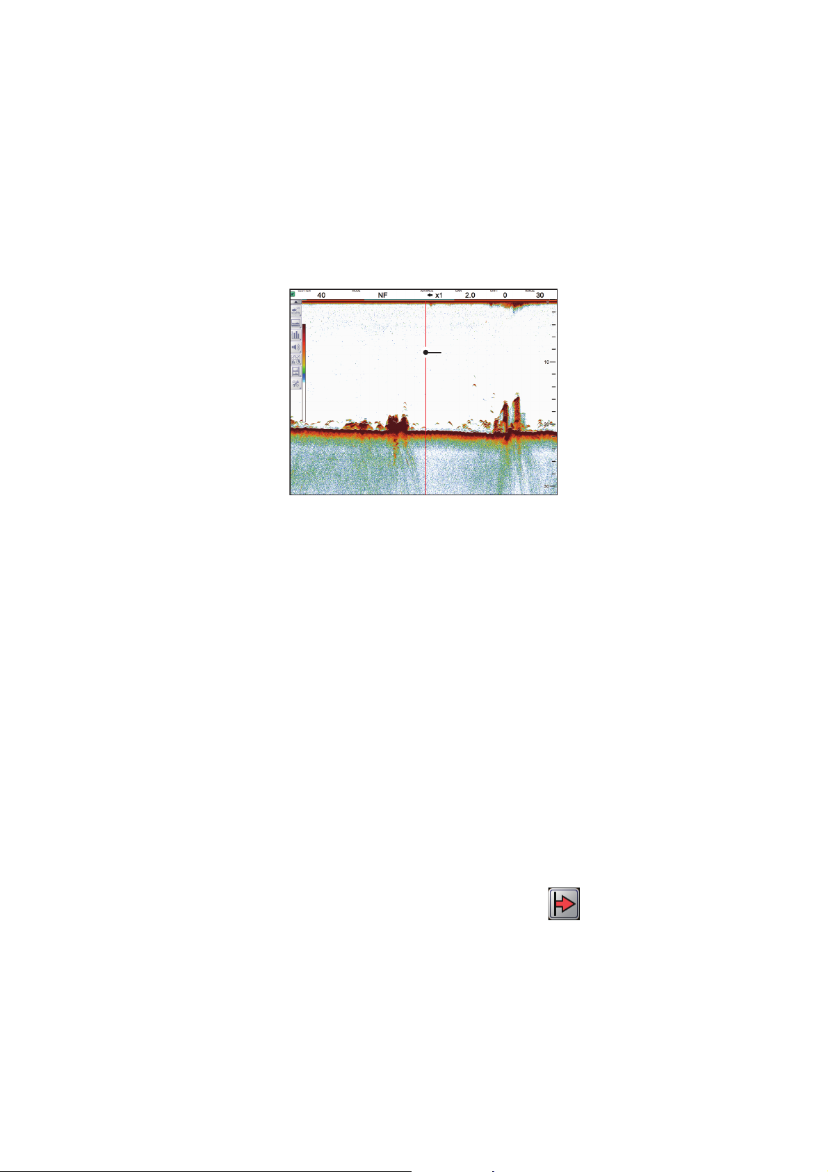
1.23 How to Inscribe TLL Lines
You can inscribe TLL (Target Latitude Longitude) lines on the display to mark the location of fish schools, shoals, or other points of interest. The position of each TLL is
output to the connected chart plotter.
Note 1: The position output function requires connection to an external EPFS device
which provides own ship position data.
Note 2: Data other than latitude and longitude can be output to connected chart plotters. (See section 5.7.2.)
Inscribed TLL
(vertical red line)
1. OPERATION
To inscribe a TLL line, place the cursor on the display location to be inscribed, then
double-click. A vertical line, red in color, appears at the location. The TLL moves with
the inscribed location. You can inscribe multiple lines at any time.
Under default settings, the FCV-2100 also outputs the TLL to the connected chart plotter.
1.24 How to Use Scroll Back Mode
Scroll back mode allows the user to view past screens of fish finder images, making it
handy for comparing fish schools sizes close to each other.
To use the scroll back mode, do the following:
1. Place the cursor on any location inside the display, other than the header, footer
or menu bar.
2. Press and hold the right button.
3. Using the Trackball, drag the screen to the right. The displayed echo moves with
the cursor and is also paused.
The display shows the scroll back mode indicator ( ) at the top-right of the
screen.
To cancel scroll back mode and return to normal echo display, select the scroll back
mode indicator.
Note: All echoes stop when scroll back mode is active. Use caution with this feature
and avoid use when the vessel is underway.
1-37
Page 50
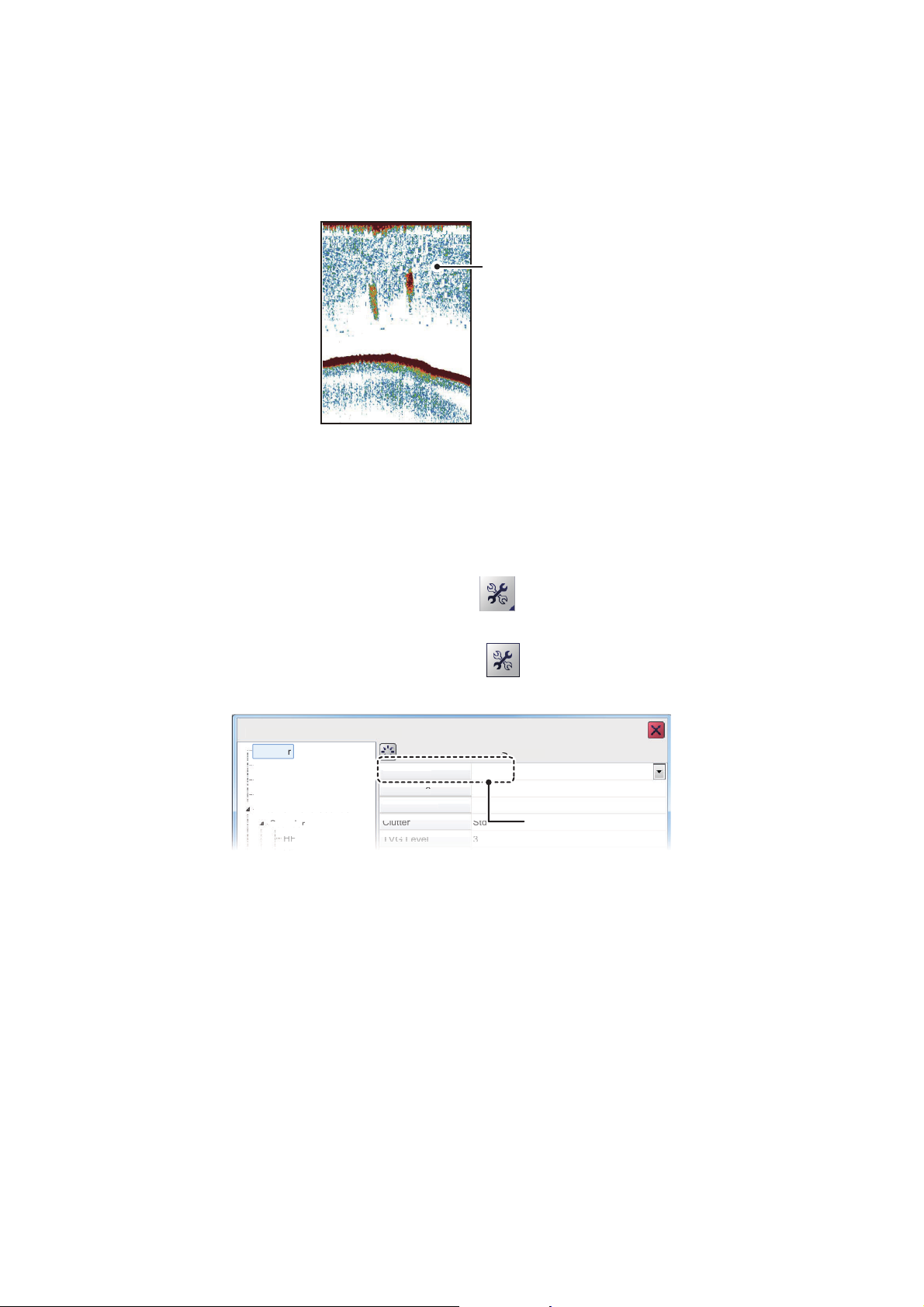
1. OPERATION
]
Sou
nde
r
C
e
Whi
te
Edg
e
WhiteMar
ker
Clu
tte
r
TVGLevel
0%
Off
Off
Std
3
Sou
nde
r
Sou
nde
r
Display
M
Alarm
Ext
ern
al
Ech
o S
oun
der
1.25 How to Erase Weak Echoes
Sediment in the water or reflections from plankton may be painted on the display in
low intensity tones, as shown in the illustration below. You can remove these unwanted echoes with the color erase feature.
Weak echoes
1.25.1 How to erase weak echoes for the FCV-2100 and external fish finders
Where [External Fish Finder Window] is set to [Off] at installation, this setting is applied to the external fish finder also.
1. Select the [Advanced Settings] icon ( ) from the InstantAccess bar™. The [Ad-
vanced Settings] menu appears.
2. Select the [Advanced Settings] icon ( ) from the [Advanced Settings] menu.
The [Advanced Settings] window appears.
FCV-2100 [ver 02524476-xx.xx
easurement
olor Eras
Color erase setting
3. The [Sounder] menu item is already selected and the [Sounder] menu appears on
the right-side of the window. Select [Color Erase] from the [Sounder] menu.
4. Adjust the [Color Erase] setting until the picture shows minimal reflections. As the
setting increases, reflections are removed in order, from weakest to strongest.
5. Select [Apply] to save the current changes and change or adjust other settings.
Select [OK] to save the current changes and close the menu window.
Select [Cancel] to abort all changes and close the menu window.
1-38
Page 51
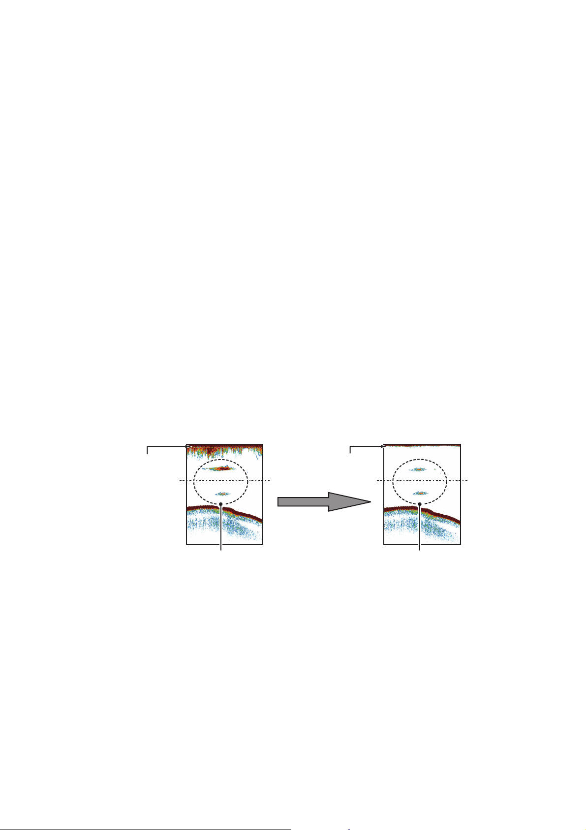
1. OPERATION
0 m
100 m
0 m
100 m
TVG OFF:
Schools of fish of equal strengths
shown in different sizes and colors.
TVG adjusted:
Schools of fish of equal strengths
shown in same sizes and colors.
Unwanted echoes
appear.
Unwanted echoes
suppressed.
1.25.2 How to erase weak echoes for external fish finders where [External Fish Finder Window] is set to [On] at installation
1. Place the cursor inside the external fish finder screen, then right-click. The [Exter-
nal Fish Finder] menu appears.
2. The [Sounder] menu is already selected.
3. Select the [Color Erase] setting. The drop-down options box appears at the far
right-side of the window.
4. Select the drop-down box, then select the appropriate color erasure level. As the
setting increases, reflections are removed in order, from weakest to strongest.
5. Select [Apply] to save the current changes and change or adjust other settings.
Select [OK] to save the current changes and close the menu window.
Select [Cancel] to abort all changes and close the menu window.
1.26 How to Adjust TVG (Time Varied Gain)
A school of fish at a deep depth is displayed in weak colors even if it is equal in
strength to one in shallow waters. This is due to propagation attenuation of the ultrasonic wave. To compensate for this difference, use TVG. TVG automatically adjusts
the gain with depth so that echoes of the same strength and different depths are
shown in the same colors regardless of their depths. The gain is increased with depth
to display echoes of equal strengths in the same colors. In the figure below, for example, the TVG is set for 100 m and the TVG level is adjusted. Then, unwanted echoes
at a distance less than 100 m are deleted and echoes at depths greater than 100 m
are not affected.
1-39
Page 52

1. OPERATION
1.26.1 How to adjust TVG for FCV-2100
The procedure outlined below is for sounders connected directly to the FCV-2100. For
external fish finder, see section 1.26.2.
1. Select the [Advanced Settings] icon ( ) from the InstantAccess bar™. The [Ad-
vanced Settings] menu appears.
2. Select the [Advanced Settings] icon ( ) from the [Advanced Settings] menu.
The [Advanced Settings] window appears.
3. The [Sounder] menu item is already selected and the [Sounder] menu appears on
the right-side of the window.
4. Select [TVG Level] from the [Sounder] menu. The adjust buttons appear to the far
right of the TVG level indication.
5. Select the button to decrease the setting, or select the button to increase the
setting. A higher setting reduces the gain for nearby echoes.
6. Select [TVG Distance]. The adjust buttons appear to the far right of the [TVG distance] indication.
7. Select the button to decrease the distance from which TVG is applied, or select
the button to increase the distance from which TVG is applied.
8. Select [Apply] to save the current changes and change or adjust other settings.
Select [OK] to save the current changes and close the menu window.
Select [Cancel] to abort all changes and close the menu window.
1-40
Page 53
1. OPERATION
S
er
TVG
STC
3
0
Sounder
LF
Display
Measu
remen
t
Alarm
]
S
STC
3
0
Sound
LF
Display
Measu
remen
t
E
Alarm
F
]
1.26.2 How to adjust TVG for external fish finders where [External Fish Finder Window] is set to [Off] at installation
1. Select the [Advanced Settings] icon ( ) from the InstantAccess bar™. The [Ad-
vanced Settings] menu appears.
2. Select the [Advanced Settings] icon ( ) from the [Advanced Settings] menu.
The [Advanced Settings] window appears.
CV-2100 [ver 02524476-xx.xx
ounder
xternal Echo Sounder
er
TVG Level
FCV-2100 [ver 02524476-xx.xx
ound
Level
External Echo Sounder
3. Select [HF] or [LF], as appropriate, from the [Sounder] item from the [External Fish
Finder] menu, on the left-side of the window. The external fish finder settings are
shown on the right-side of the window.
4. Select the [TVG Level] setting. The adjust buttons appear to the far right of the
TVG level indication.
5. Select the button to decrease TVG, or select the button to increase TVG.
This setting affects the DFF3 and DDF1-UHD as shown below.
• DFF1-UHD: Increase the setting to increase gain at close range.
• DFF3: Decrease the setting to increase gain at close range.
6. Select [Apply] to save the current changes and change or adjust other settings.
Select [OK] to save the current changes and close the menu window.
Select [Cancel] to abort all changes and close the menu window.
1.26.3 How to adjust TVG for external fish finders where [External
Fish Finder Window] is set to [On] at installation
1. Place the cursor inside the external fish finder screen, then right-click. The [Exter-
nal Fish Finder] menu appears.
2. The [Sounder] menu is already selected.
3. Select the frequency for the sounder you want to adjust. [HF] for high frequency,
[LF] for low frequency. The settings for the selected frequency appear on the rightside of the window.
4. Select [TVG Level]. The adjust buttons appear to the far right of the TVG distance
indication.
5. Select the button to decrease TVG, or select the button to increase TVG.
This setting affects the DFF3 and DDF1-UHD as shown below.
• DFF1-UHD: Increase the setting to increase gain at close range.
• DFF3: Decrease the setting to increase gain at close range.
6. Select [Apply] to save the current changes and change or adjust other settings.
Select [OK] to save the current changes and close the menu window.
Select [Cancel] to abort all changes and close the menu window.
1-41
Page 54
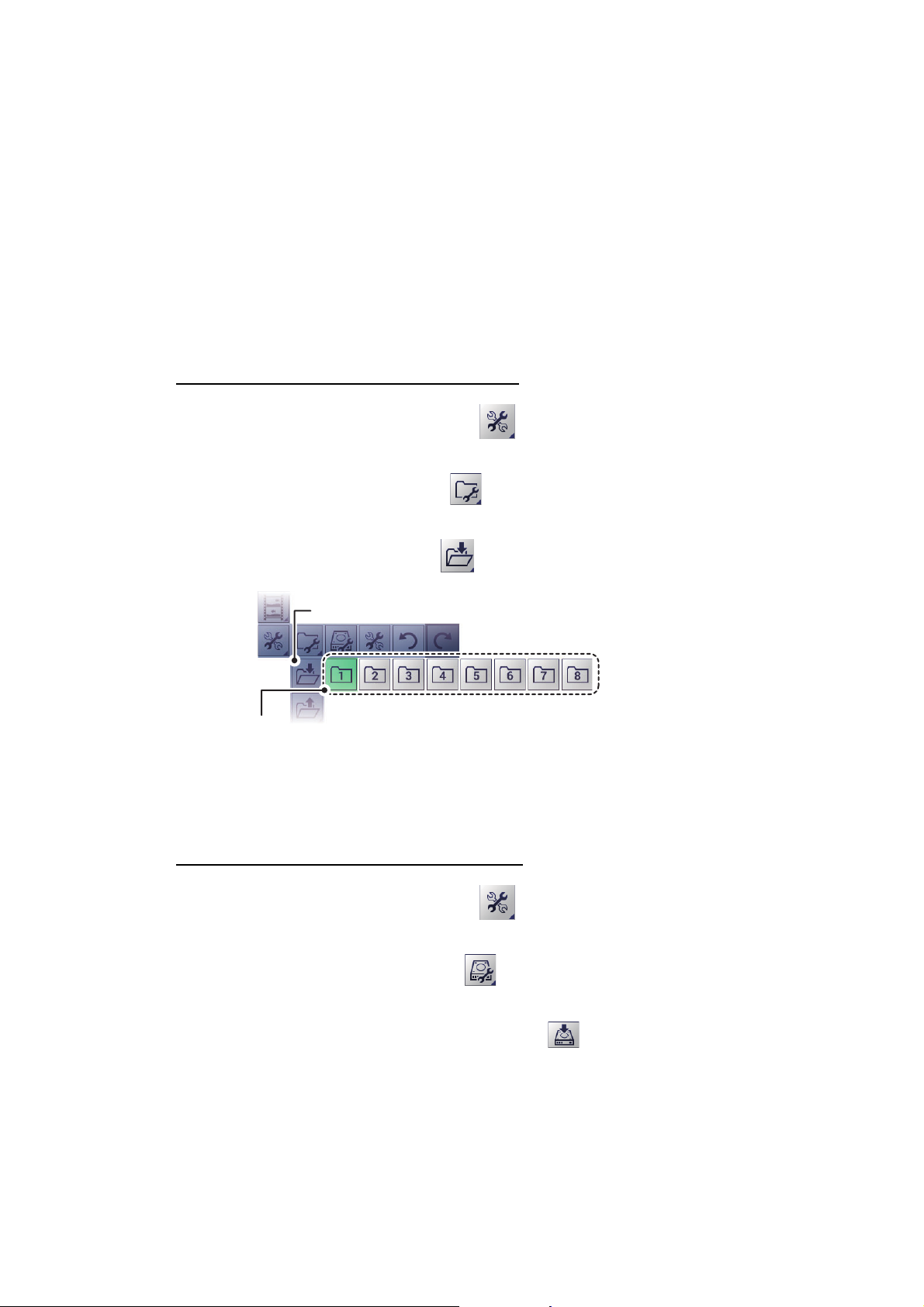
1. OPERATION
1.27 How to Save and Load Settings
Settings can be stored to, or loaded from, either the FCV-2100 internal memory or an
external storage device.
1.27.1 How to save settings
The internal memory can store up to 8 settings variations. For external memory, the
maximum number of settings variations which can be stored depends on the external
memory’s available capacity.
Note: Settings which have been over-written (saved over) cannot be restored. Always
check that the save location is correct before starting the save procedure.
How to save settings to internal memory
1. Select the [Advanced Settings] icon ( ) from the InstantAccess bar™. The [Ad-
vanced Settings] menu appears.
2. Select the Internal Setting icon ( ). The internal setting save/load icons ap-
pear.
3. Select the Save Settings icon ( ). The save slot icons appear.
[
Save Settings] icon
Save slot icons. Green: In use, but can over-write;
Gray: Unused.
4. Select the save slot you want to use. A confirmation message pop up appears after the save process is complete.
5. Select [OK] to close the pop up.
How to save settings to external memory
1. Select the [Advanced Settings] icon ( ) from the InstantAccess bar™. The [Ad-
vanced Settings] menu appears.
1-42
2. Select the [External Setting] icon ( ). The external setting save/load icons ap-
pear.
3. Select the [Save External Unit Settings] icon ( ). A confirmation message pop
up appears after the save process is complete.
Note: If there is no external memory connected, the [Save External Unit Settings]
icon is gray and not selectable.
4. Select [OK] to close the pop up.
Page 55
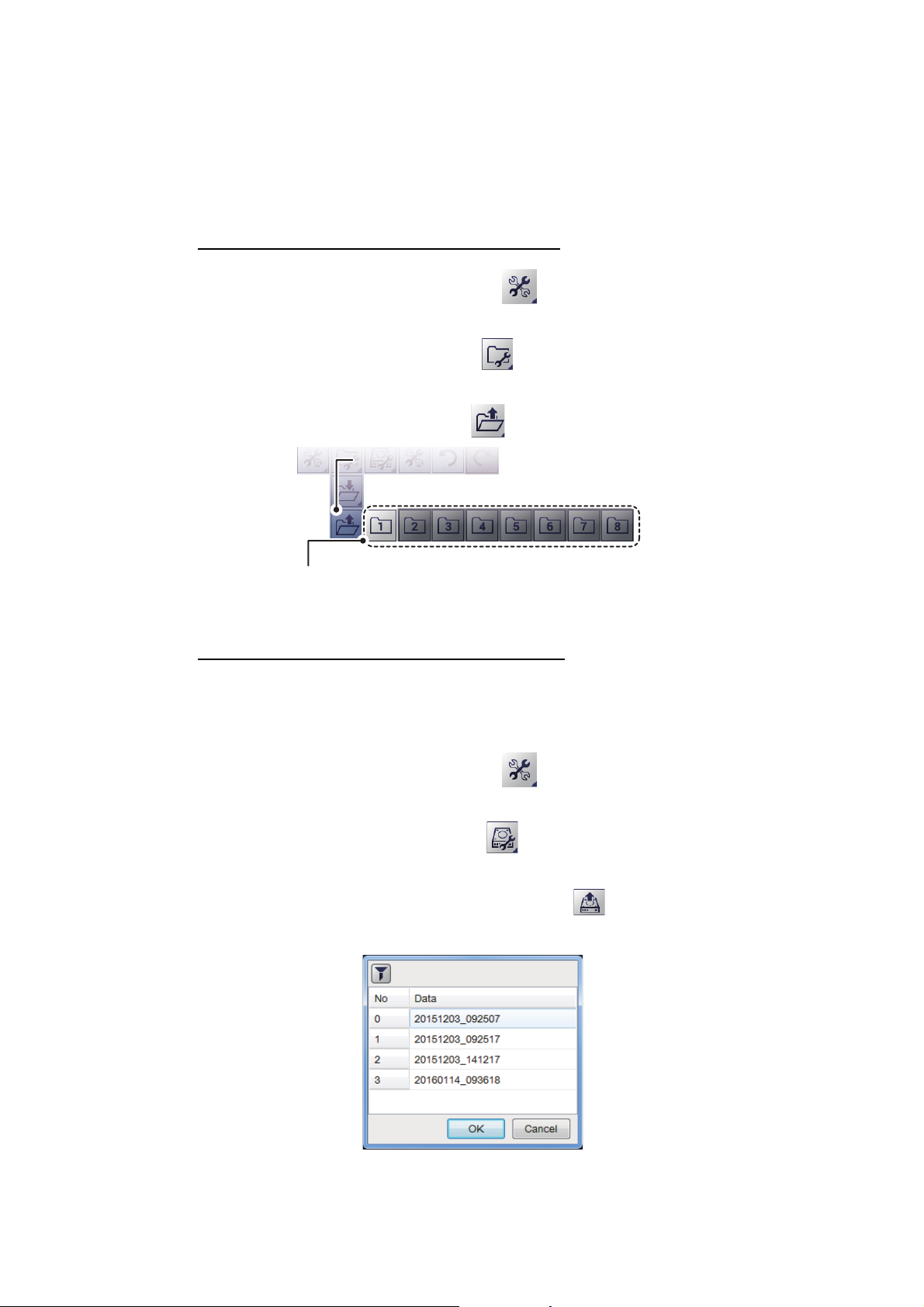
1.27.2 How to load settings
[
Load Settings] icon
[
Load Settings] icon
Load slot icons. Light-gray: Available to load from.
Dark-gray: No data saved.
Previously saved settings can be loaded from their save location, either internal or external location, at any time.
Note: When the load procedure is complete, previous settings cannot be restored.
Check that the settings to be loaded are correct before starting the procedure.
How to load settings from internal memory
1. Select the [Advanced Settings] icon ( ) from the InstantAccess bar™. The [Ad-
vanced Settings] menu appears.
2. Select the [Internal Setting] icon ( ). The internal setting save/load icons ap-
pear.
3. Select the [Load Settings] icon ( ). The load slot icons appear.
1. OPERATION
4. Select the load slot you want to use. The system applies the loaded settings.
How to load settings from external memory
Note: This method requires connection to an external memory device. If there is no
device connected, the [Load External Unit Settings] icon shown in the procedure below are not available.
1. Select the [Advanced Settings] icon ( ) from the InstantAccess bar™. The [Ad-
vanced Settings] menu appears.
2. Select the [External Setting] icon ( ). The external setting save/load icons ap-
pear.
3. Select the [Load External Unit Settings] icon ( ). A pop up window listing the
available settings files appears.
4. Select the settings file to load.
5. Select [OK] to close the pop up.
1-43
Page 56
1. OPERATION
1.28 How to Undo/Redo Operations
The system stores the last 20 operations in temporary memory. This allows you to “undo” a mistaken operation, or several mistaken operations, at any time. You can also
“redo” an operation which was undone.
Note 1: The temporary memory is cleared when the power is turned off. The [Undo]
and [Redo] functions are not available when the system restarted.
Note 2: The [Undo] and [Redo] functions are available only when an operation can be
undone or redone, respectively.
How to undo an operation
1. Select the [Advanced Settings] icon ( ) from the InstantAccess bar™. The [Ad-
vanced Settings] menu appears.
2. Select the [Undo] icon ( ). The last operation is undone.
3. Repeat step 2 as required.
How to redo an operation
1. Select the [Advanced Settings] icon from the InstantAccess bar™. The [Advanced
Settings] menu appears.
2. Select the [Redo] icon ( ). The last operation is redone.
3. Repeat step 2 as required.
1-44
Page 57
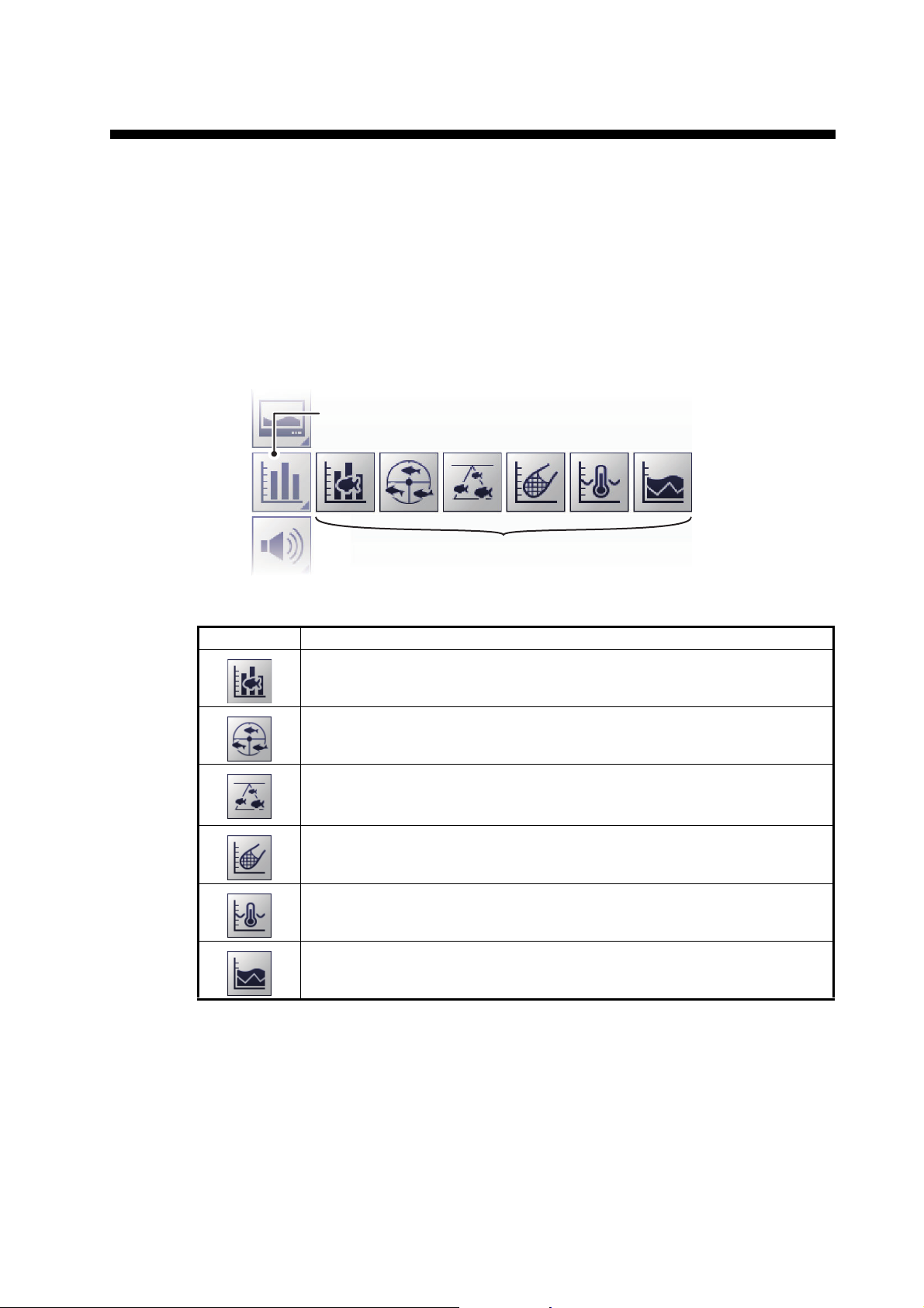
2. GRAPH FUNCTIONS
[
Graph] icon
[
Graph] menu
The FCV-2100 can display up to six graphs (listed in section 2.1, below), depending
on vessel configuration.
2.1 How to Show/Hide Graphs
All graphs can be shown/hidden to suit your requirements. To show/hide a graph, do
the following:
1. Select the [Graph] icon from the InstantAccess bar™. The [Graph] menu appears.
[
Graph] icon
[
Graph] menu
2. Select the appropriate graph to show/hide. The icon changes color accordingly,
green for shown, gray for hidden.
Menu icon Description
[Fish Size Graph]: Select to show/hide a bar graph which displays estimated fish size and related data (see section 2.2).
[Vertical Target Graph]: Select to show/hide a graph which displays detected fish schools below your vessel (see section 2.3.1).
[Horizontal Target Graph]: Select to show/hide a graph which displays
fish schools detected in the stern direction of your vessel (see
section 2.3.2).
[Sonde Graph]: Select to show/hide a plotted graph which displays depth
and water temperature data fed from the net sonde (see section 2.4).
[Temp Graph]: Select to show/hide a plotted graph which displays the
water temperature as a dotted line across the screen (see section 2.5).
[Hardness Graph]: Select to show/hide a graph which displays the estimated hardness of the seabed (see section 2.6).
You can select multiple graphs to be displayed at the same time.
2-1
Page 58
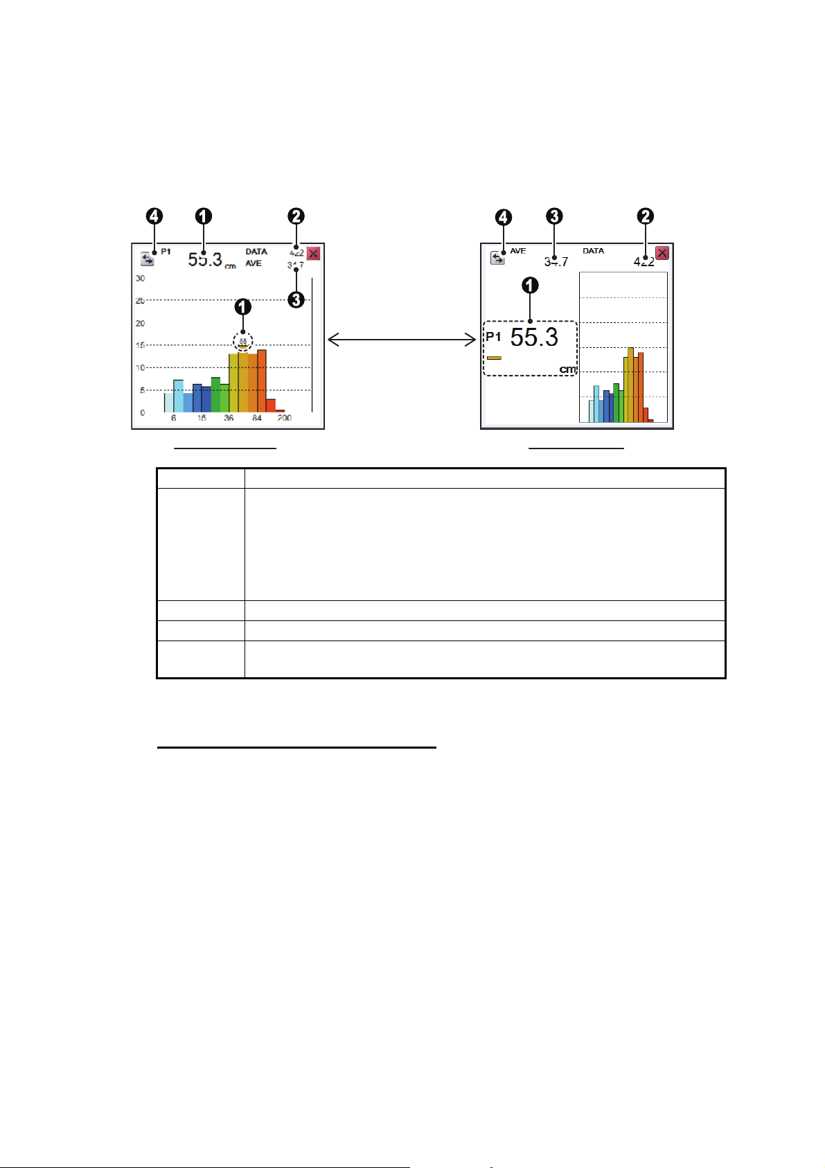
2. GRAPH FUNCTIONS
2.2 Fish Size Graph
The [Fish Size Graph] displays the fish size and distribution in a bar graph format.
In the following example, fish size (in centimeters) is shown from left to right and the
distribution (as a percentage) is shown from bottom to top.
Graph emphasis Peak emphasis
Press the [Switch
display] button to
switch between
display formats.
No. Description
1 Estimated size of the largest fish detected (peak size) detected. Depend-
ing on the setting selected at [Graph Peak] in the [Measurement] menu,
you can display up to the third largest fish (P1 to P3). (See section 2.2.7
for details.)
Note: When the graph emphasis format is selected, only the estimated
size of the largest fish (P1) is displayed.
2 Total number of fish detected.
3 Overall average size of fish detected.
4 [Switch Display] button. Select to switch between graph emphasis and
peak emphasis display formats.
[Fish Sizes Graph]s can be moved to any location on the screen. Drag and drop the
graph to move it.
Notices regarding the fish size graph
• Fish at depths of less than two meters cannot be measured. However, if [Zero Line
Rejector] is set to [On], fish within the area covered by the transmission line cannot
be detected.
• In a school of fish, the echoes overlap. This causes a greater margin of error in fish
size measurement.
• Echo intensity depends on fish species. When the fish length differs between the
indicated length and the actual length, you can compensate the difference on the
[Calibration] menu (see section 4.7.5).
2-2
Page 59
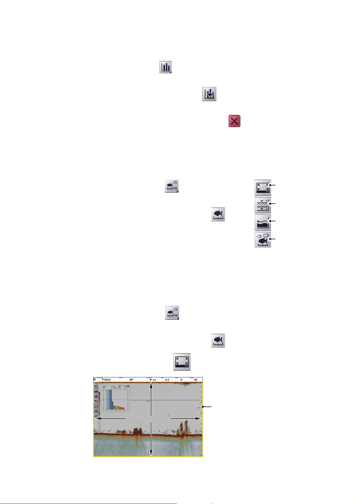
2.2.1 How to show/hide the fish size graph
Detection rangeDetection range
Measurement marker
(yellow box)
To show/hide the [Vertical Target Graph], do the following:
1. Select the [Graph] icon ( ) from the InstantAccess bar™ to show the [Graph]
menu.
2. Select the [Vertical Target Graph] icon ( ). The icon changes to a green color
and the [Vertical Target Graph] appears.
To close the graph, select the [Close Window] icon ( ), or select the graph icon.
2.2.2 How to set the method of measurement
The FCV-2100 has four methods of fish size measurement.
To select, or change, the method of measurement, do the following:
2. GRAPH FUNCTIONS
1. Select the [Sounder] icon ( ) from the InstantAccess
bar™. The [Sounder] menu bar appears.
2. Select the [Fish Size Measurement] icon ( ). The
menu options appear.
3. Select the appropriate method of measurement icon, referring to the figure to the right.
2.2.3 Entire Area
This method measures all detected fish. When this method is active, the area of detection (the entire screen) is surrounded with a yellow box, as shown in the example
figure below.
1. Select the [Sounder] icon ( ) from the InstantAccess bar™. The [Sounder]
menu bar appears.
2. Select the [Fish Size Measurement] icon ( ). The menu options appear.
[Entire Area]
[Specific Range]
[Bottom Trace]
[Specific Area]
3. Select the [Entire Area] icon ( ).
2-3
Page 60
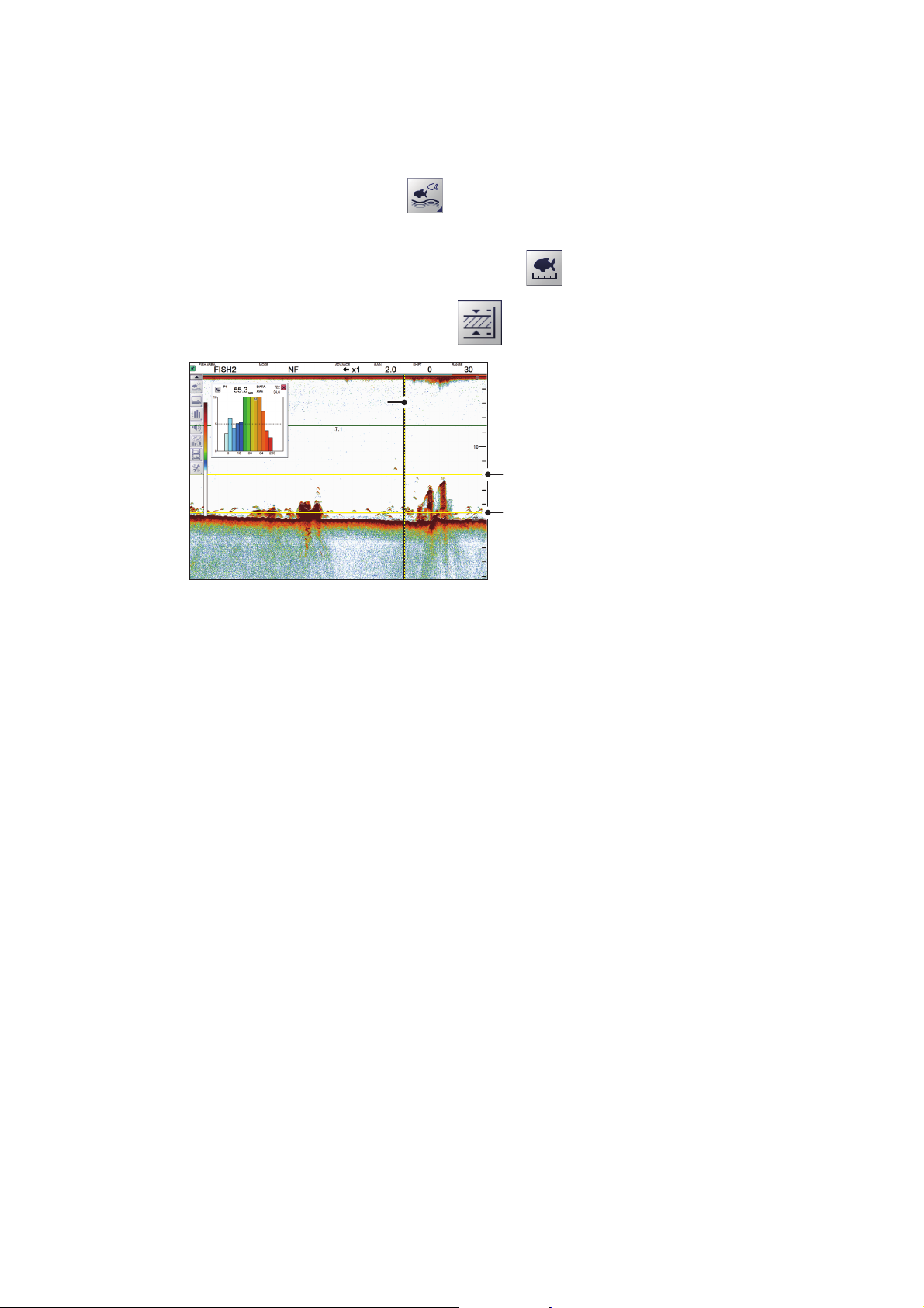
2. GRAPH FUNCTIONS
Upper limit bar
Lower limit bar
Measurement locationMeasurement location
The area between the upper
limit bar and lower limit bar is
the “specified area” .
2.2.4 Specific Range
This method produces three marker lines, one vertical and two horizontal, which can
be adjusted to set the specified range.
1. Select the [Sounder] icon ( ) from the InstantAccess bar™. The [Sounder]
menu bar appears.
2. Select the [Fish Size Measurement] icon ( ). The menu options appear.
3. Select the [Specific Range] icon ( ).
4. Adjust the area to suit your requirements.
Drag and drop the upper limit bar to move the upper and lower range limit bars
together.
Drag and drop the lower limit bar to adjust the width of the range.
Drag and drop the measurement location to set where the fish measurements are
made.
2-4
Page 61
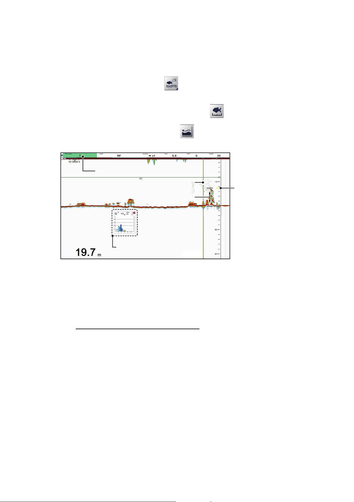
2.2.5 Bottom Trace
Measurement locationMeasurement location
Measurement range settingMeasurement range setting
Measurement range
marker. This marker
moves in relation to the
seabed, maintaining the
distance set at [Fish
Track] on the Header.
Measurement range
marker. This marker
moves in relation to the
seabed, maintaining the
distance set at [Fish
Track] on the Header.
Fish size graph shows fish
sizes within the selected range.
Measurement rangeMeasurement range
This method produces two marker lines. The horizontal, small line at the right-hand
edge of the screen is the measurement range marker. The vertical line is the measurement location.
1. Select the [Sounder] icon ( ) from the InstantAccess bar™. The [Sounder]
menu bar appears.
2. Select the [Fish Size Measurement] icon ( ). The menu options appear.
3. Select the [Bottom Trace] icon ( ). [FISH TRACK] appears in the Miscellaneous section of the header.
2. GRAPH FUNCTIONS
Drag and drop the measurement location to set where the fish measurements are to
be made.
Note: Where the depth indication (bottom left-hand side of the screen) shows bars "-
- - -" instead of a depth value, the measurement range marker and measurement lo-
cation are not shown. In this case, the measurement method is automatically changed
to [Entire Area].
How to adjust the measurement range
The measurement range marker moves dynamically, keeping a set range from the
seabed. To change the range, do the following:
1. Select the [FISH TRACK] indication at the far left-hand side of the header. The indication is highlighted in green color.
2. Scroll to change the range. The range marker moves with each change in range.
2-5
Page 62
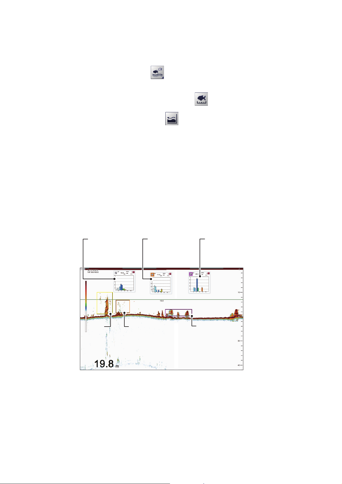
2. GRAPH FUNCTIONS
[
FISH1
]
measurement
area
(Yellow)
[
FISH2
]
measurement
area
(Orange)
[
FISH3
]
measurement
area
(Purple)
2.2.6 Specific Area
This method allows you to specify up to three square-shaped areas. To set up one or
more detection areas, do the following:
1. Select the [Sounder] icon ( ) from the InstantAccess bar™. The [Sounder]
menu bar appears.
2. Select the [Fish Size Measurement] icon ( ). The menu options appear.
3. Select the [Specific Area] icon ( ). [FISH AREA] appears in the Miscellaneous section of the header.
4. Select the [FISH AREA] indication on the header. The indication is highlighted in
green color.
5. Scroll to change the area you want to set. The indication reads "FISH1", "FISH2"
or "FISH3", depending on your selection.
6. Place the cursor at the one corner of the area, then press and hold the left button.
7. Drag the cursor to the diagonally opposite corner of the area, then release the left
button. The selected area is now highlighted with a colored box. The color changes, depending on the area number selected (see the list below for reference).
[FISH1]: Yellow, [FISH2]: Orange, [FISH3]: Purple.
When set, each area’s graph also appears, as shown in the example figure below.
[
FISH1] graph
(background color
for [Switch Display]
button is white)
[
FISH1]
measurement
area
(Yellow)
[
measurement
area
(Orange)
[
FISH2] graph
(background color
for [Switch Display]
button is orange)
FISH2]
[
FISH3] graph
(background color
for [Switch Display]
button is purple)
[
FISH3]
measurement
area
(Purple)
2-6
To move an area drag the top line of an area to the desired location.
To adjust the size of an area, drag the sides or bottom line of an area.
Page 63
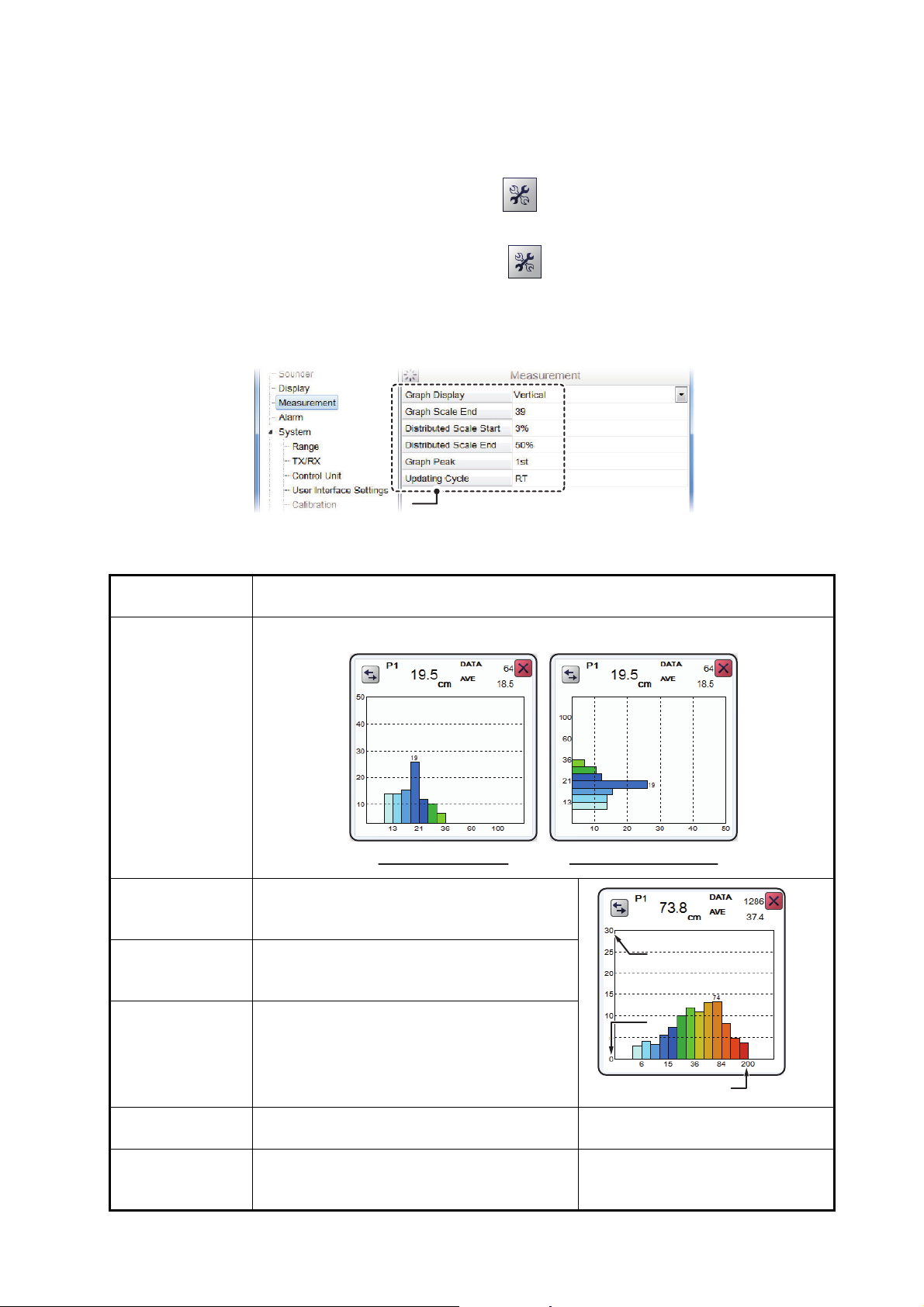
2.2.7 How to change graph settings
Measurement settingsMeasurement settings
Vertical graph bars Horizontal graph bars
[
Distributed Scale End
][
Distributed Scale End
]
[
Graph Scale End
][
Graph Scale End
]
[
Distributed Scale Start
][
Distributed Scale Start
]
Several aspects of the graphs can be changed. To change graph settings, do the following:
1. Select the [Advanced Settings] icon ( ) from the InstantAccess bar™. The [Ad-
vanced Settings] menu appears.
2. Select the [Advanced Settings] icon ( ) from the [Advanced Settings] menu.
The [Advanced Settings] window appears.
3. Select [Measurement]. The [Measurement] settings appear in the right-side of the
window.
2. GRAPH FUNCTIONS
4. Referring to the table below, select the measurement option to change, then
change the settings as required.
Measurement
setting
[Graph Display] Set the orientation of the graph. Select [Horizontal] or [Vertical] as required.
[Graph Scale
End]
[Distributed Scale
Start]
[Distributed Scale
End]
Set the maximum fish size to be displayed
on the graph.
(See the figure to the right.)
Set the percentage of distribution at which
data starts to appear on the graph. (See the
figure to the right.)
Set the percentage of distribution at which
data stops appearing on the graph. (See
the figure to the right.)
Description
[Graph Peak] Set the number of peak measurement to
display on the graph.
[Updating Cycle] Set the interval at which to update graphs. [RT]: Real Time
[P1]: Show only the highest peak
measurement.
[1s], [2s], [3s]: Interval, in seconds.
2-7
Page 64
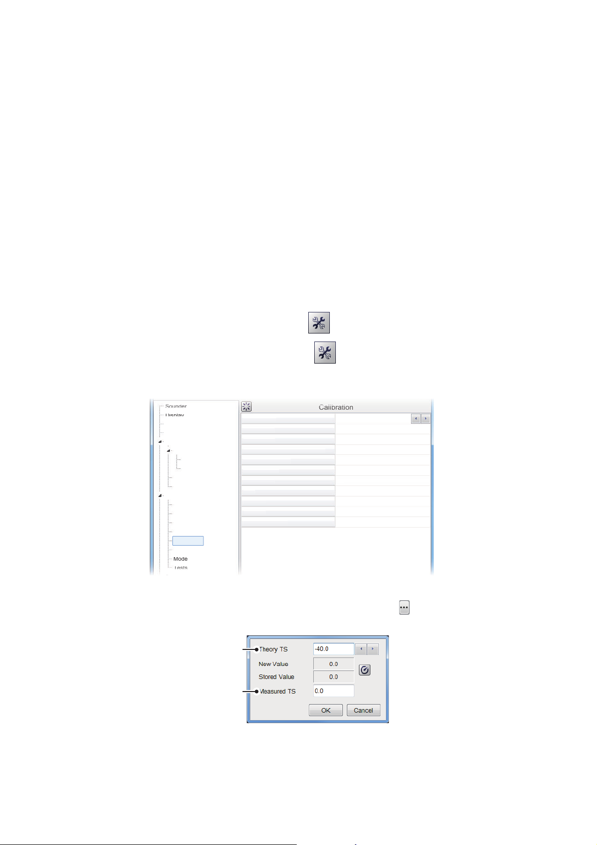
2. GRAPH FUNCTIONS
Soun
der
Cal
ibr
ati
on
S
T
ure
B
l
P
n
Z
n
Z
Zero
Lin
e Fi
ll
G
ADJ
F
C
ing
1500.0
0.0
0.0
0.0
0.0
Off
Off
4
0
0
0
Soun
der
Disp
lay
M
E
r
Alarm
System
Rang
TX/R
X
TX/
C
C
C
S
n
Mode
Test
s
U
Calibration
sphere
size
Measured
size
2.2.8 How to calibrate the target echo strength
To accurately analyze fish distribution, it is necessary to calibrate target strength using
a calibration sphere with a diameter of at least 38.1 mm. The calibration is done to
match the target strength value displayed in the fish histogram dialog box with the target strength value of the calibration sphere.
To calibrate the target strength, do the following:
1. Suspend a calibration sphere at least 3 m below the transducer.
2. Set the measurement mode to [Specific Area] (see section 2.2.2).
3. Adjust the area marker (colored rectangle, see section 2.2.6) to place the calibration sphere echo inside the measurement area. Keep the measurement area
small, to avoid unwanted echoes.
4. Check the fish size displayed on the graph in comparison to the calibration
sphere. Note that calibration can be completed if there are other echoes present.
5. Confirm that the calibration sphere echo appears inside the area marker in consecutive scans before proceeding to the next step.
6. Select the [Advance Settings] icon ( ) from the InstantAccess bar™.
7. Select the [Advanced Settings] icon ( ) from the Menu bar. The [Advanced
Settings] menu is displayed.
easurement
xternal Echo Sounde
alibration
RX
e
ontrol Unit
ser Interface Settings
alibration
tabilizatio
ound Speed
emperat
ottom Leve
osition to Start Bottom Detectio
ero Line Rejectio
ero Line Area
Draft
ain
ish Size
alibration Sett
.5
8. Select [Calibration]. The [Calibration] options appear on the right of the menu.
9. Select [Calibration Setting], then select the detail icon ( ) to the right-side of the
calibration value. The settings pop up window shown below appears.
2-8
10. Adjust the value to match the size of the calibrations sphere. Press to decrease
the value, press to increase the value.
Page 65
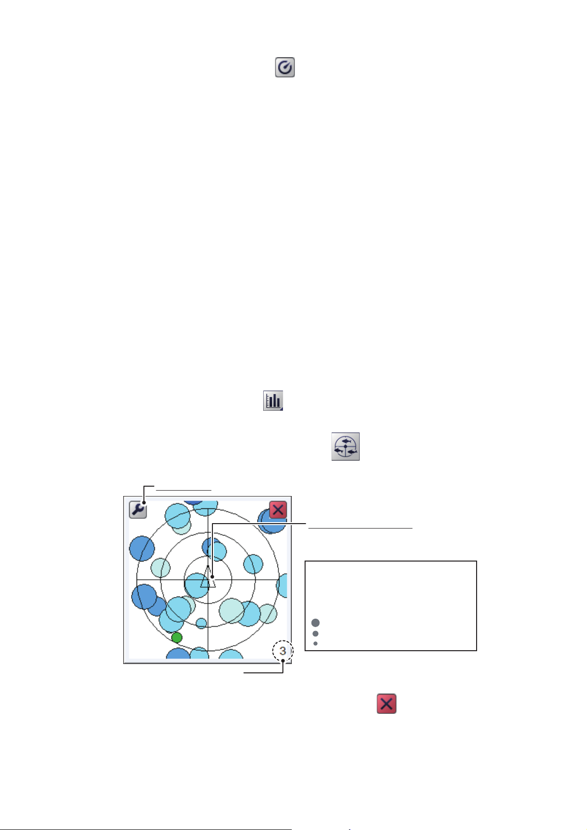
11. Select the calibrate button ( ). The system measures the size of the calibration
sphere and the measurement appears in the [Measured TS] indication.
12. Select [OK] to apply the calibration settings. To cancel the new settings, select
[Cancel].
2.3 Target Graphs
The target graphs plot fish locations in relation to your vessel. The [Vertical Target
Graph] shows fish below your vessel and the [Horizontal Target Graph] shows fish in
the stern direction.
Note: The measurement area for the target graphs is shared with the [Fish Size
Graph].
2.3.1 Vertical target graph
With a “bird’s-eye-view” of fish below your vessel and your vessel at the center of the
graph display, this graph mode is ideal for keeping track of your heading in relation to
fish schools and also determining fish distribution surrounding your vessel.
2. GRAPH FUNCTIONS
Fish echoes from the last three scans are displayed, which helps to track schools.
To show the [Vertical Target Graph], do the following:
1. Select the [Graph] icon ( ) from the InstantAccess bar™ to show the [Graph]
menu.
2. Select the [Vertical Target Graph] icon ( ). The icon changes to a green color
and the [Vertical Target Graph] appears.
Scale button (see section 2.3.3)
Own ship icon (triangle)
The upper area of the graph
window is current heading direction.
Echoes detected from the last three
scans are shown in the graph. Echo
colors range from green (weak) to red
(strong). The echo size indicates the
time at which the echo was detected.
: Latest echo
: Echo from last pulse
: Echo from two pulses past
Graph scale
(unit: degrees (°))
To close the graph, select the [Close Window] icon ( ), or select the graph icon.
2-9
Page 66
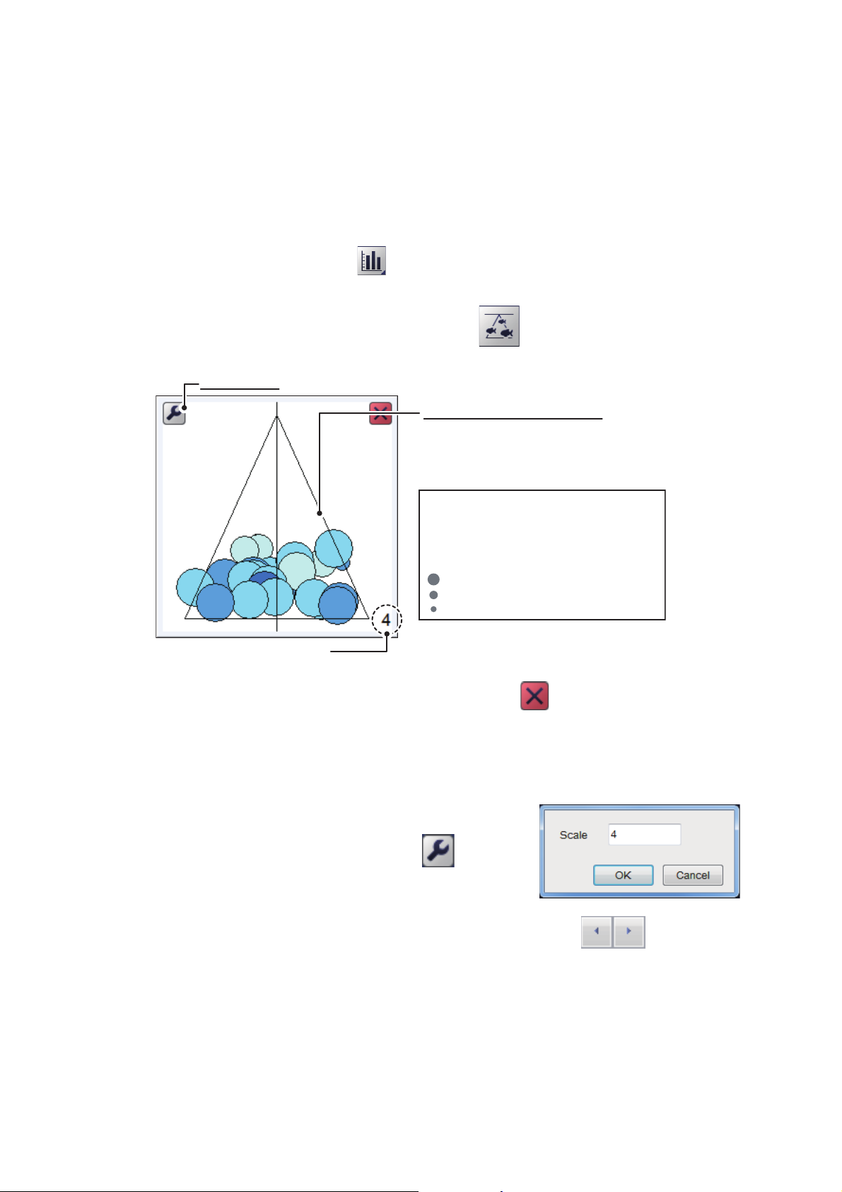
2. GRAPH FUNCTIONS
Scale button (see section 2.3.3)
Measurement area (triangle)
The measurement area in the
graph changes shape
depending on the size of the
specified measurement area.
Echoes detected from the last three
scans are shown in the graph. Echo
colors range from green (weak) to red
(strong). The echo size indicates the
time at which the echo was detected.
: Latest echo
: Echo from last pulse
: Echo from two pulses past
Graph scale
(unit: degrees (°))
2.3.2 Horizontal target graph
The [Horizontal Target Graph] mode gives a view of fish echoes in the stern direction.
The depth at which the echoes were detected and the distribution is displayed, making
this mode ideal for estimating the type of fish.
Fish echoes from the last three scans are displayed, which helps to track schools.
To show the [Horizontal Target Graph], do the following:
1. Select the [Graph] icon ( ) from the InstantAccess bar™ to show the [Graph]
menu.
2. Select the [Horizontal Target Graph] icon ( ). The icon changes to a green
color and the [Horizontal Target Graph] appears.
To close the graph, select the [Close Window] icon ( ), or select the graph icon.
2.3.3 How to change the graph scale (target graphs only)
To change the target graph scale, do the following:
1. With either the vertical or horizontal target graph
displayed, select the scale button ( ) at the top
left of the graph. The scale settings window appears.
2. Select the [Scale] value. The setting adjustment buttons ( ) appear.
3. Select to decrease or to increase the scale. The available range is 2° to 8°
from directly below own ship. A larger setting gives a wider detection area.
4. Select [OK].
2-10
Page 67
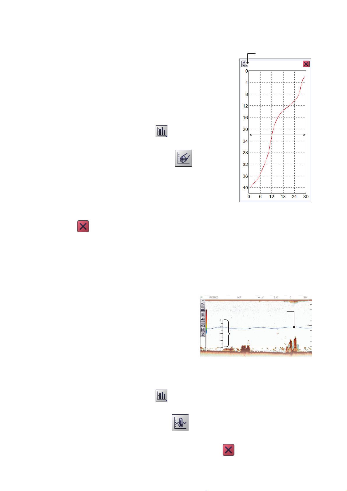
2.4 Sonde Graph
Horizontal axis: temperature
[
Refresh] button
Vertical axis: depth
Display
range
Display
range
Water temperature graphWater temperature graph
Graph scaleGraph scale
The [Sonde Graph] plots depth and water temperature
data, input from a net sonde, in a red line.
The data displayed is input from the net sonde with the
lowest number in the list of sondes selected at [Sonde
Mark] from the [Display] section of the [Advanced Settings] menu. (See section 4.3.)
To show the [Sonde Graph], do the following:
1. Select the [Graph] icon ( ) from the InstantAc-
cess bar™ to show the [Graph] menu.
2. Select the [Sonde Graph] icon ( ). The icon
changes to a green color and the [Sonde Graph]
appears.
The depth and temperature at the sonde location
appears on the graph. The depth scale reflects any
changes to the fish finder depth scale.
2. GRAPH FUNCTIONS
To close the graph, select the [Close Window] icon
( ), or select the graph icon.
Note: You can clear the [Sonde Graph] and start a new graph at any time. Select the
[Refresh] button (indicated in the figure above) to clear the graph and start a new
graph.
2.5 Temp Graph
The [Temp Graph] plots water temperature,
input from an external temperature sensor,
in a blue dotted line across the screen.
Note 1: A water temperature sensor must
be connected to use this feature.
Note 2: The data source for water temperature input is set at installation. For details,
consult your local dealer.
To show the [Temp Graph], do the following:
1. Select the [Graph] icon ( ) from the InstantAccess bar™ to show the [Graph]
menu.
2. Select the [Temp Graph] icon ( ). The icon changes to a green color and the
[Temp Graph] appears.
To close the graph, select the [Close Window] icon ( ), or select the graph icon.
2-11
Page 68
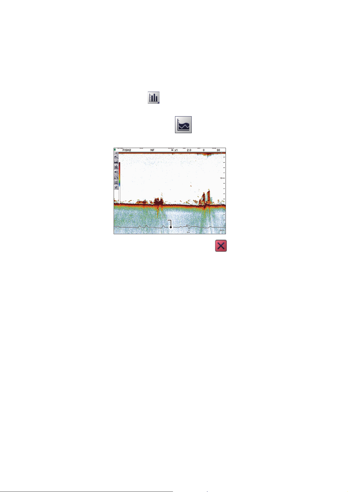
2. GRAPH FUNCTIONS
Hardness graphHardness graph
2.6 Hardness Graph
The [Hardness Graph] plots the estimated seabed hardness as a solid line graph
along the bottom of the screen. The graph indicates estimated composition, such as
rocks or gravel, making it a handy tool for finding the right fishing spot.
to show the [Hardness Graph], do the following:
1. Select the [Graph] icon ( ) from the InstantAccess bar™ to show the [Graph]
menu.
2. Select the [Hardness Graph] icon ( ). The icon changes to a green color and
the [Hardness Graph] appears.
To close the graph, select the [Close Window] icon ( ), or select the graph icon.
2-12
Page 69
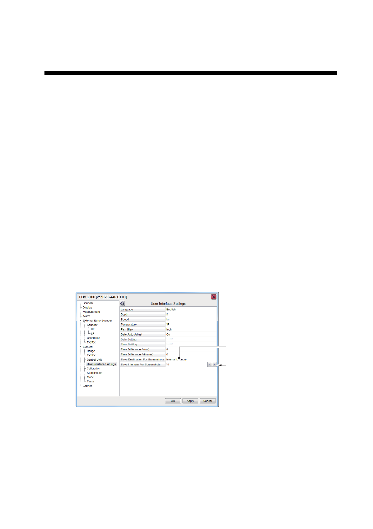
3. STILL IMAGES & DATA RECORD-
Recording destination option
Options button
ING
3.1 Still Images (Screenshots)
You can save a screenshot of the on-screen display and play it back at any time. This
is helpful when comparing fish school sizes.
Note: This function is not available on sub monitors.
3.1.1 How to set the save destination for images
Images can be saved to the Processor Unit’s internal memory, or to an external device. The Processor Unit can hold up to 99 image files. For external devices, the number of files that can be saved depends on the capacity of the external device.
To set the save destination for images, do the following:
1. Select the [Advance Settings] icon from the InstantAccess bar™.
2. Select the [Advanced Settings] icon from the Menu bar. The [Advanced Settings]
menu is displayed.
3. Double-click [System] to show the [System] section of the menu.
4. Select [Setting]. The [Setting] options are shown to the right-side of the menu.
5. Select the [Screenshot Recording Destination] option (indicated in the figure below). The options button is now visible.
6. Select the options button, then select the appropriate destination. The available
options are:
[Internal Memory] - saves the images to the Processor Unit.
[External Memory] - saves the images to the connected external device.
7. Select [Apply], then [OK], in that order. The destination is now set for saved images.
3-1
Page 70
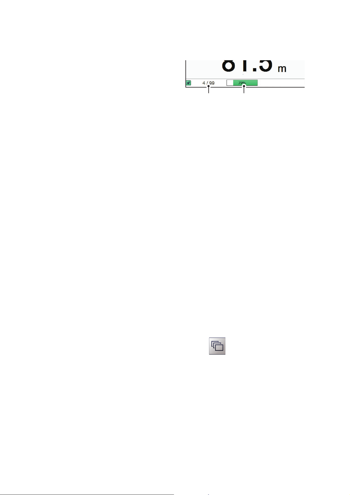
3. STILL IMAGES & DATA RECORDING
3.1.2 How to take a still image (screenshot)
To take a screenshot, press the wheel on the Trackball Control Unit.
Where the save destination is set to [Internal Memory], the footer shows the
total number of screenshots saved to
the Processor Unit.
Internal memory
image count
Where the save destination is set to [External Memory], the footer shows the percentage of space available on the external device.
The file format for saved images is JPEG (Joint Photographic Experts Group).
Note 1: Where the internal or external memory has insufficient space to save a new
image, the error message "Not enough memory to save screenshot. Delete unnecessary files." appears.
To rectify the problem, do one of the following:
• Delete unnecessary files (see section 3.1.6).
External memory
capacity
• Moved saved files to an external device (see section 3.1.5).
Note 2: If a still image is taken when [External Memory] is selected and no external
device is connected, the error message "External memory is not connected." appears.
Check that the external memory is connected correctly.
3.1.3 How to take still images at a set interval
Several still images can be taken at set intervals. To use this function, do the following:
Note 1: The interval (in seconds) at which still images are recorded is set at [Screenshot Recording Interval] in the [System] section of the [Advanced Settings] menu.
Note 2: Connect the external device to the USB port on the Processor Unit. Do not
connect the external device to the USB port on the Trackball Control Unit.
Note 3: [Static Display Recording: Start/Stop] is not selectable from the menu if the
external device is not correctly connected.
1. Select [Echo Recording] from the InstantAccess bar™.
2. Select the [Multi-Screenshot Start/Stop] icon ( ) from the [Echo Recording]
menu. Still images are now saved at regular intervals and the [Static Display Recording: Start/Stop] icon is displayed in green color.
3-2
3. Select the [Static Display Recording: Start/Stop] icon to stop recording.
Page 71
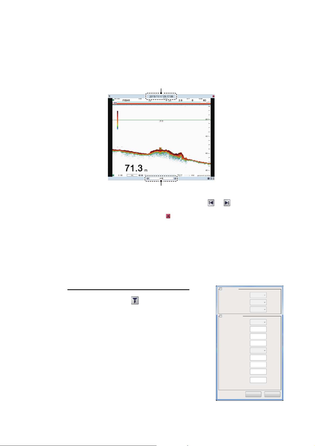
3.1.4 How to replay a still image
Specify Date
Year
Month
Day
- - - -
- - - -
- - - -
N
0
0
0
E
0
0
0
50
Degree
Minute
Second
Degree
Minute
Second
Specify Position
Latitude
Longitude
Radius [nm]
OK Cancel
To replay a saved still image, press and hold the wheel on the Trackball Control Unit.
The replay screen is displayed and the oldest still image is shown. A total of 1000 images can be load to replay.
Note: Replay is not available on sub monitors.
Filename (Date and time the file was saved)
3. STILL IMAGES & DATA RECORDING
Playlist location (current image/total images)
To change the displayed file, press the arrow buttons ( or ).
To close the replay screen, press the icon a the top-right of the screen.
Note 1: Where there are no still images to play back and the wheel on the trackball is
pressed and held, a blank screen (black color) appears.
Note 2: The indication for the number of current images and total images is located at
the bottom of the screen (see figure above). This indication shows the number images
at the time of opening the replay screen and does not reflect any new images taken
while the replay screen is open. To refresh the count, close, then re-open the replay
screen.
How to filter the images that are displayed
1. Select the filter icon ( ) at the top-left of the screen
to show the filtering options pop up window (shown
to the right).
2. Select the appropriate check box to show the filtering
options. You can select either of, or both of the filters.
• [Specify Date]: Apply a filter based on date. you
can select a single filter (for example, filter by
month only) or a mixed filter (for example, filter by
year, month and date).
• [Specify Location]: Apply a filter based on a spe-
cific location and/or a nautical mile radius from the
specified point.
3. Select [OK] to apply the filters.
3-3
Page 72
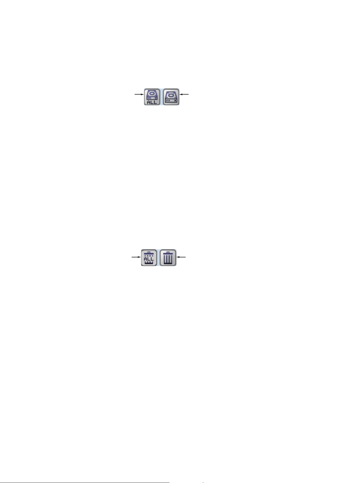
3. STILL IMAGES & DATA RECORDING
Copy all image files to
the external device.
Copy the current image
file to the external device.
3.1.5 How to copy images from internal to external memory
You can copy image files from the internal memory of the Processor Unit to an external device (for example a USB flash drive).
1. Press and hold the wheel on the trackball to show the replay screen.
2. Select the appropriate icon at the bottom-right of the screen.
The images are copied from the Processor Unit to the connected external device.
Note 1: If the external device does not have the capacity to store the image files, the
error message "Not enough memory to copy screenshot. Delete unnecessary files."
appears.
To rectify this problem, delete unnecessary files from the device to create room for the
image files, then repeat the above procedure.
Note 2: If no external device is connected, the [Copy] and [Copy All] icons are gray in
color and not available.
3.1.6 How to delete image files
You can delete image files in two manners: individually, or all at once. To delete image
files, do the following:
1. Press and hold the wheel on the trackball to show the replay screen.
2. At the bottom-right of the screen, select the appropriate icon.
Delete all
images.
A confirmation message is displayed.
3. Select [Yes] to proceed with the file deletion. Select [Cancel] to abort the file deletion.
Delete images
singularly.
3-4
Page 73
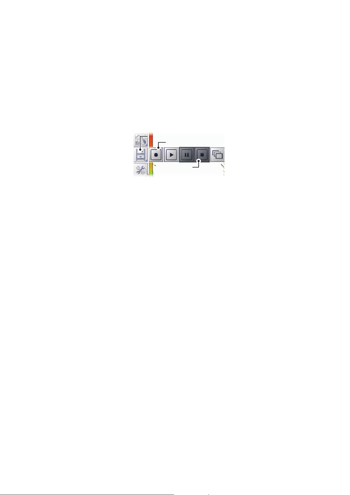
3. STILL IMAGES & DATA RECORDING
Record iconRecord icon
Stop iconStop icon
Echo Recording menu iconEcho Recording menu icon
3.2 Echo Data Recording and Playback
The echo data recording and playback function requires connection to an external
memory device. Echo data is recorded as a “movie”, allowing you to playback previously recorded echo data, such as fish schools, at your convenience.
3.2.1 How to record echo data
To start data recording, select the [Echo Recording] menu icon from the InstantAccess
bar™, then select the [Record] icon. To stop the recording at any time, select the
[Stop] icon.
The amount of memory used for recording echo data varies, depending on configuration and settings. For example, with no external fish finder connected, no display division and the range set to 150 m, the estimated memory usage is 4.7 GB per hour.
Note 1: When there is no external memory device connected, the [Echo Recording]
icon is not selectable.
Note 2: An external device with 500 GB capacity, or higher, is recommended for this
function.
Note 3: Connect the external device to the USB port on the Processor Unit. Do not
connect the external device to the USB port on the Trackball Control Unit.
Note 4: When an external memory device is connected and the capacity for the device
reaches its limit, recording is stopped and the message "Recording stopped because
memory capacity is full. Check capacity." appears.
Delete unnecessary files from the external device, or take other appropriate measures
to allow sufficient capacity to save the echo data.
Note 5: When the external memory device does not have sufficient memory to begin
data recording, and you attempt to record data, the message "Not enough memory to
start recording. Delete unnecessary files." appears.
Delete unnecessary files from the external device, or take other appropriate measures
to allow sufficient capacity to save the echo data.
3-5
Page 74
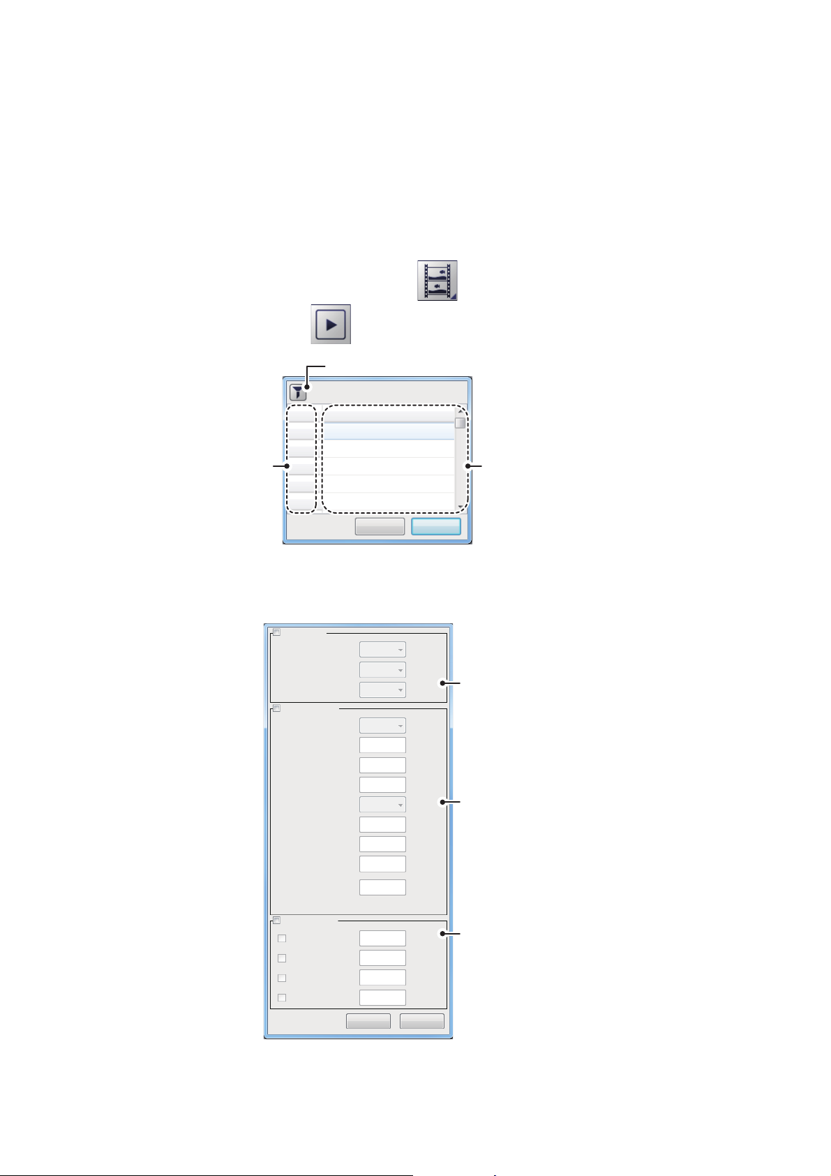
3. STILL IMAGES & DATA RECORDING
Filter button
File number
File name (date/time
the file was created)
File name (date/time
the file was created)
No
OK Cancel
0
1
2
3
4
20160115120523
20160116120523
20160201120535
20160201153522
21060222212250
Data
3.2.2 How to play back recorded echo data
The playback function lets you view echo data you previously recorded. The display
mode used for playback should match the settings used when the echo data was recorded, or the echoes may not be displayed correctly.
Adjustments made to gain and other echo settings are not reflected to the echo data
being played back.
To play back recorded echo data, do the following:
1. Select the [Echo Recording] icon ( ) from the InstantAccess bar™, then se-
lect the Play icon ( ). The file selection dialog shown below appears.
2. If you need to filter the files, select the filter button, indicated in the above figure.
The filter options window, shown below, appears. If you have no need to filter the
files, go to step 4.
Specify Date
Year
- - - -
Month
- - - -
Date filter
options
Position filter
options
Record filter
options
Specify Position
Latitude
Second
Longitude
Second
Radius [nm]
Sort Recordings
Minimum Time
Maximum Time
Minimum Depth
Maximum Depth
Day
Degree
Minute
Degree
Minute
- - - -
N
0
0
0
E
0
0
0
50
1
2
40
80
OK Cancel
3-6
Page 75
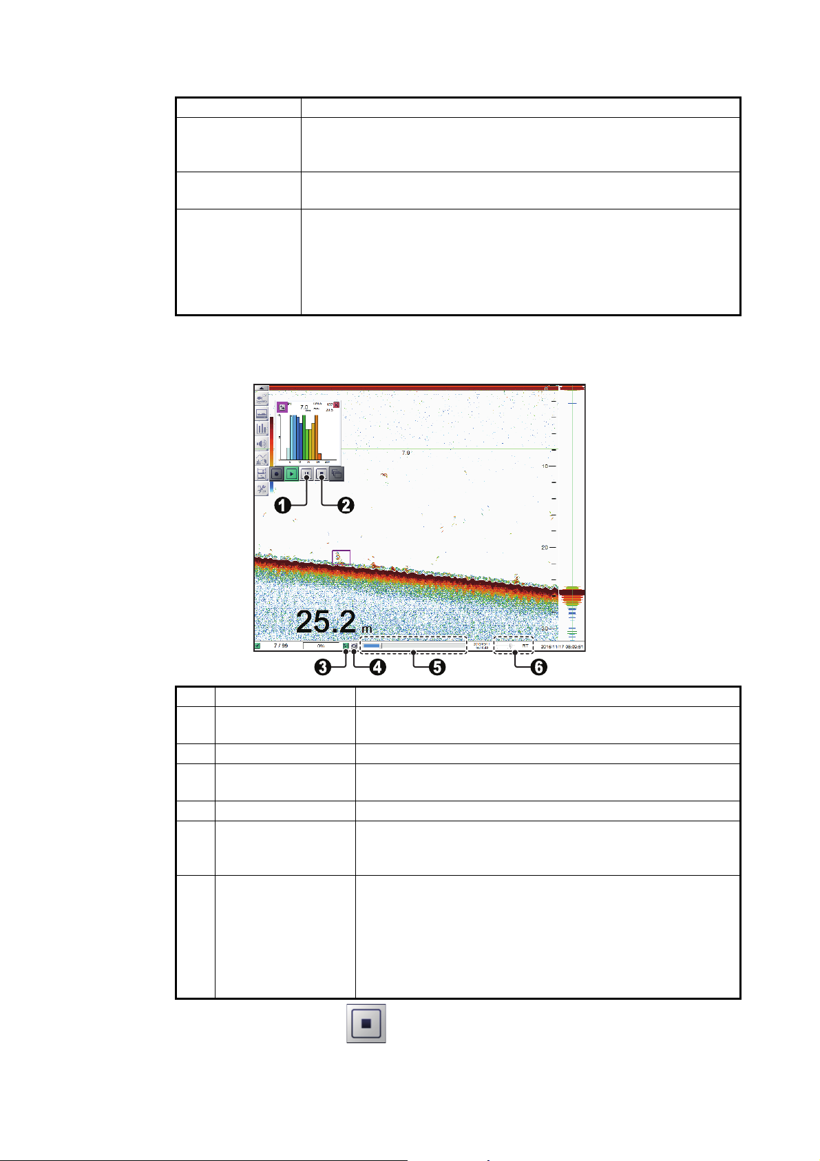
3. STILL IMAGES & DATA RECORDING
3. Referring to the table below, set the appropriate file filters, then select [OK].
Filter type Description
[Specify Date] Apply a filter based on date. You can select a single filter (for exam-
ple, filter by month only) or a mixed filter (for example, filter by year,
month and date).
[Specify Position] Apply a filter based on a specific location and/or a nautical mile ra-
dius from the specified point.
[Specify Record] Apply a filter based on the playback time of the record, the depth re-
corded, or a mix of time and depth.
• [Minimum Time]/[Minimum Depth]: Records with a time/depth below this setting are not displayed.
• [Maximum Time]/[Maximum Depth]: Records with a time/depth
above this setting are not displayed.
4. Select the file to play back, then select [OK]. The selected file is played back.
Some settings, such as gain and fish size measurements, can be adjusted during
playback.
No. Name Description
1 [Pause] icon Select to pause the playback. Select the [Play] icon to con-
tinue playback.
2 [Stop] Icon Select to stop the playback.
3 [Settings] icon Apply your current settings to the playback file. This icon is
shown in green color when in use.
4 [Loop] icon Select to loop the playback.
5 [Playback Location]
indicator
6 [Playback Speed] Select the speed to playback the record. The available op-
Indicates your current location in the overall playback. Se-
lect the slide bar, then drag the locater to change the play-
back location.
tions are:
• [2000]/[1500]/[1000]/[500] ms: Play the record at the set
millisecond speed.
• [RT]: Play the record at real time speed (the speed at
which it was recorded).
• [MAX]: Play the record at maximum playback speed.
5. Select the Stop icon ( ) to stop the playback.
3-7
Page 76
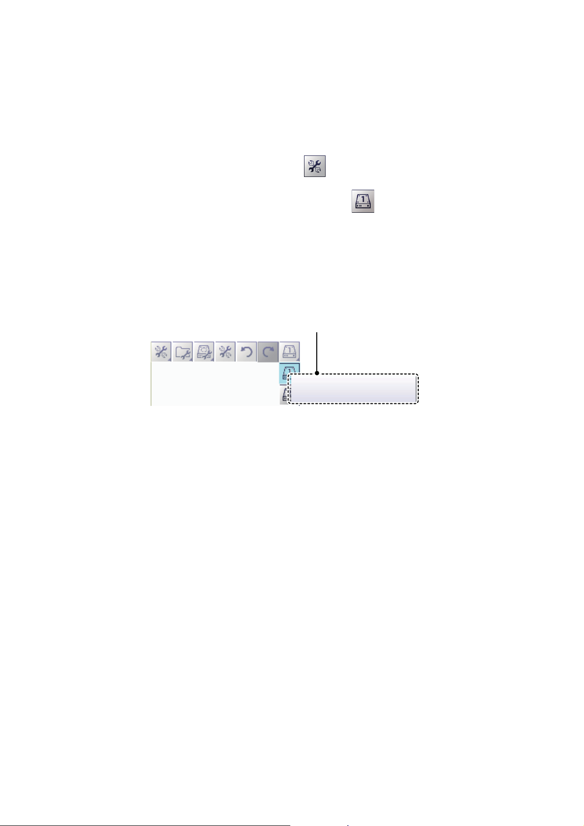
3. STILL IMAGES & DATA RECORDING
External Recording Media 1
(734.43/931.51 [GB])
External Recording Media (memory
device) details
(Available space/Maximum capacity)
3.3 How to Select an External Memory Device
Where more than one external memory device is connected to the FCV-2100, you can
select the device which will be used for data recording and saving still images*.
*: [Screenshot Recording Destination] must be set to [External Memory] to save still
images to an external memory device.
1. Select the [Advance Settings] icon ( )from the InstantAccess bar™.
2. select the [Select External Recording Media] ( ) icon.
Note: The [Select External Recording Media] icon is only displayed when there is
more than one external memory device connected to the FCV-2100.
3. Select the appropriate external memory device to use.
When the cursor is place on the icon for an external memory device, the highlighted device’s capacity (available space/maximum space) is displayed.
3-8
Page 77
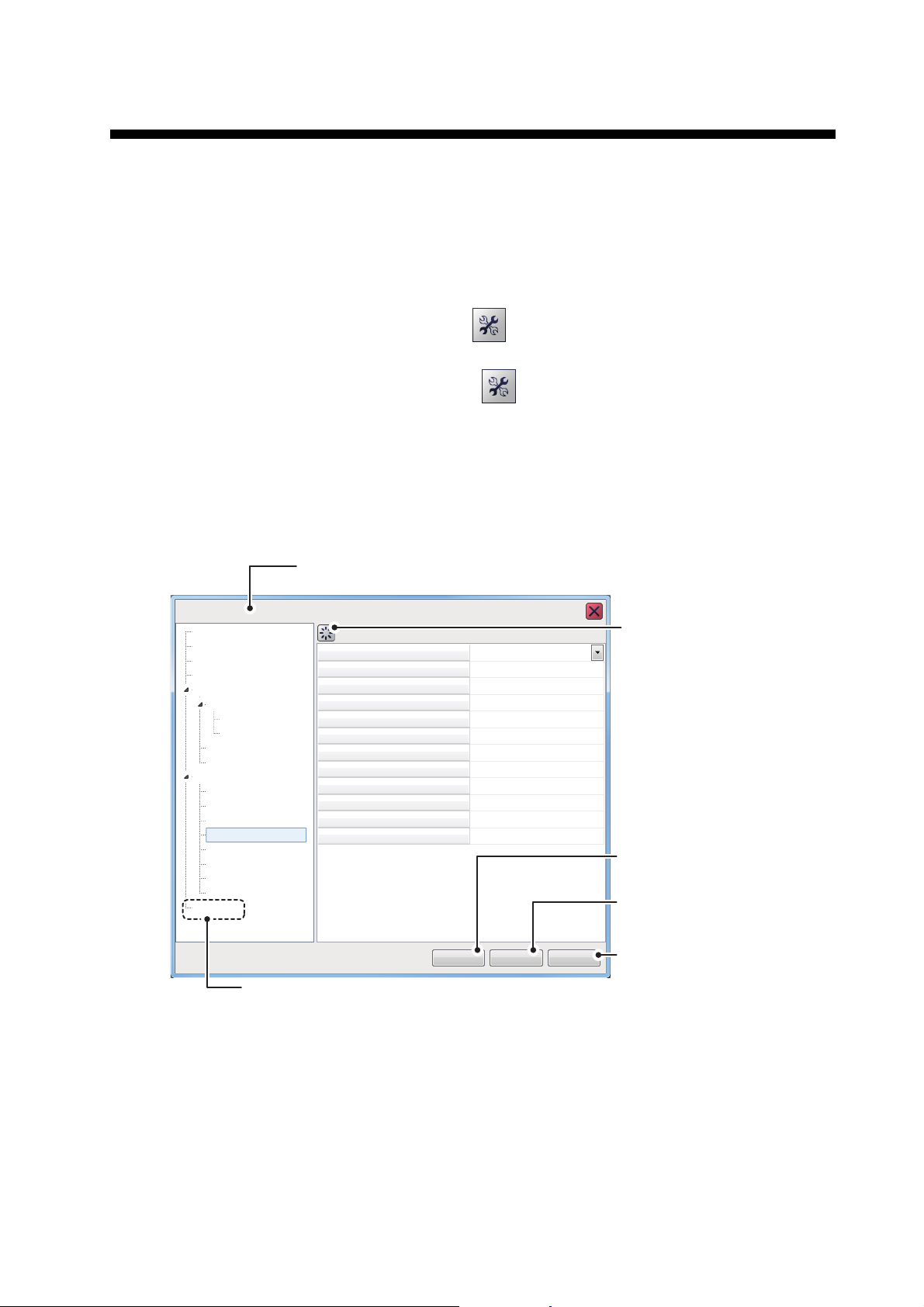
4. ADVANCED SETTINGS
FCV-2100 [ver 02524476-xx.xx]
User Interface Settings
Range
Language
Depth
Speed
Temperature
Fish Size
Date Auto Adjust
Time Difference (Hour)
Time Difference (Minutes)
Save Destination For Screenshots
Save Intervals For Screenshots
OK Apply Cancel
Date Setting
Time Setting
English
ft
kn
°F
inch
On
0
0
Internal Memory
10
******
******
TX/RX
TX/RX
Control Unit
User Interface Settings
Calibration
Calibration
Stabilization
Mode
Tests
Service
System
Select this icon to
reset the current
menu settings to
factory default.
Accessible only by
service personnel.
Accessible only by
service personnel.
Confirm changes and
close the menu.
Apply changes.
(Menu remains open).
Cancel changes and
close the menu.
Sounder
Sounder
HF
LF
Display
Measurement
Alarm
External Echo Sounder
Software version (program number)
“xx.xx” denotes minor changes.
The Advanced Settings menu contains various settings, such as [Sounder], [Display]
and [Measurement] settings.
4.1 How to Access the Advanced Settings Menu
Select the [Advance Settings] icon ( ) from the InstantAccess bar™.
Select the [Advanced Settings] icon ( ) from the Menu bar. The [Advanced Set-
tings] menu is displayed.
Where [External Fish Finder Window] is set to [On] at installation, you can access external fish finder settings from a sub monitor by right-clicking a non-interactive section
of the screen. The external fish finder settings are not available from the [Advance Settings] menu. (See section 4.8.)
Note: External Fish Finder settings are displayed below [Alarm] if [External Fish Finder Window] is set on [Off] at installation and an external fish finder is connected correctly.
4-1
Page 78
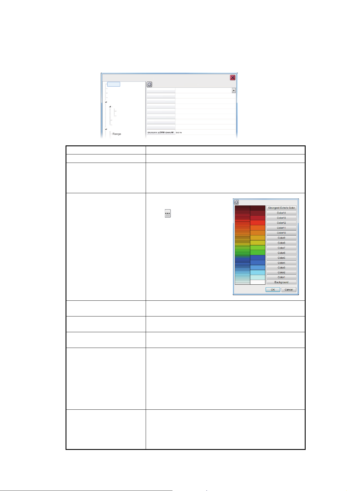
4. ADVANCED SETTINGS
F
]
S
Rang
g
g
e
C
ge
Whi
rker
Clut
ter
TVG
Leve
l
TVG
Bott
om Z
one
Belo
w
STC
B
0%
Off
Off
Std
3
3
85%
85%
0
5096TX/
C
Sy
m
S
Soun
der
HF
LF
Display
Meas
ent
Alarm
E
r
4.2 Sounder Menu
The [Sounder] section of the [Advanced Settings] menu contains the settings for
sounders connected to the FCV-2100. For external sounders, see section section 4.6.
CV-2100 [ver 02524476-xx.xx
ounder
urem
xternal Echo Sounde
olor Erase
ounder
White Ed
te Ma
alibration
ste
RX
Distance
ottom Zone Above
Menu item Description
[Color Erase] Erase unwanted noise. See section 1.25.
[White Edge] Gives the seabed echo a white edge. Useful when trying
to separate bottom-feeding fish from the seabed. Set a
high value for a thick white line or a low value for a thin
white line. Set to [Off] to disable this function.
[White Marker] Displays selected echoes in
white color. Select the detail
icon ( ) to show the color
selection pop up window,
shown to the right.
Select the echo color to be
displayed as white, then select [OK].
To cancel all changes, select
[Cancel].
4-2
[Clutter] Remove unwanted echoes (sediment, etc.). See
section 1.11.
[TVG Level] Time Varied Gain. Adjusts the TVG level. See
section 1.26.
[TVG Distance] Adjust the maximum distance at which TVG is applied.
See section 1.26.
[STC] Sensitivity Time Control. Remove unwanted echoes near
the surface. Use this function when you want to see fish
near the surface clearly.
Set the STC value according to your requirement. A setting of [0] disables the STC.
Note: A high STC setting can erase fish echoes. It is recommended to watch your display when adjusting the
STC.
[Bottom Zone Above] &
[Bottom Zone Below]
Set the are in which the seabed is displayed when autorange mode is active.
Note: This menu item is available only if [Auto Range] is
not selected from the [Range] → [Auto] menu under the
[System] menu.
Page 79
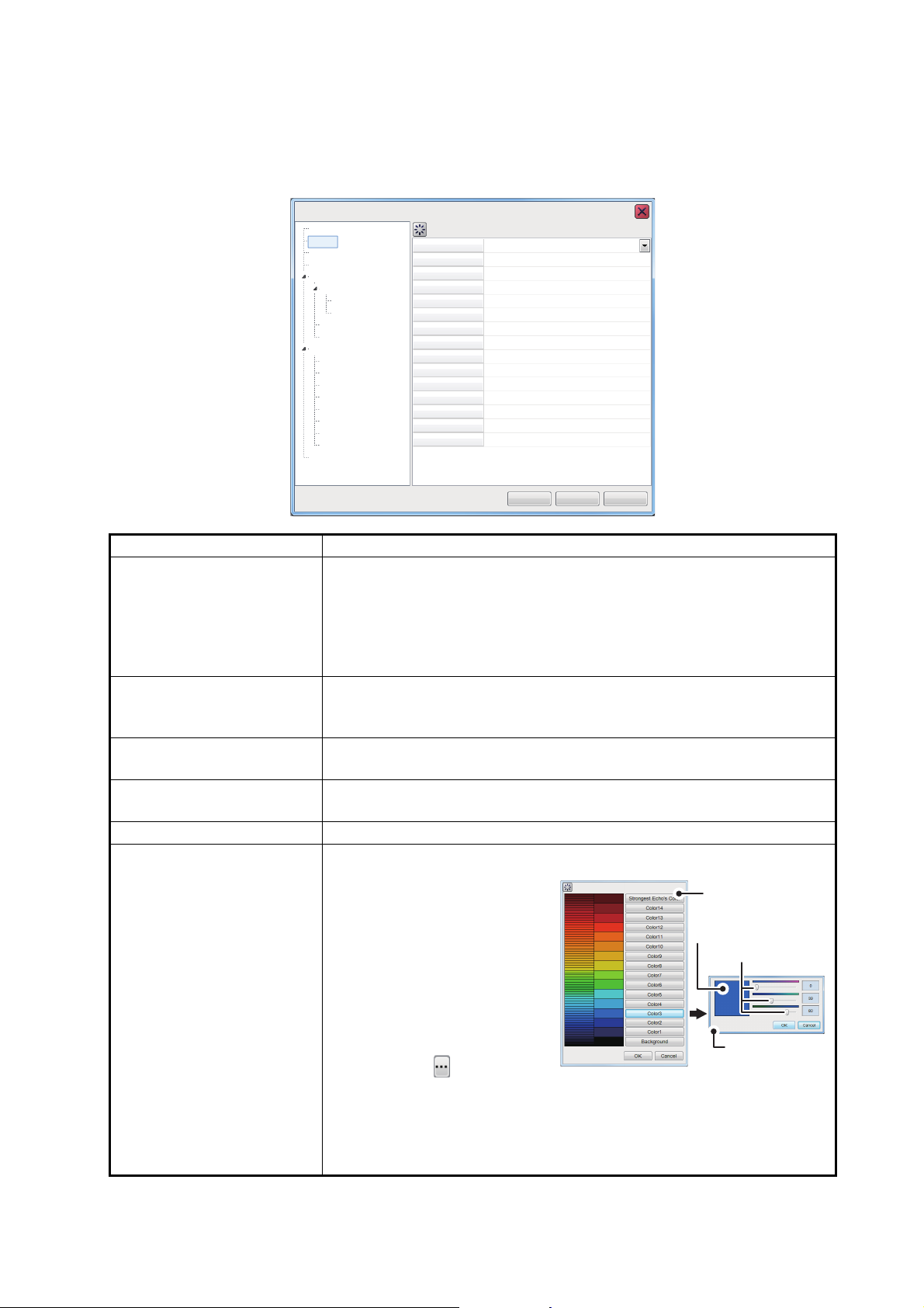
4.3 Display Menu
Sounder
Display
A-Scope
Temp Graph
Temp Color
Zoom Marker
Colors
Hue
Custom
Custom
******
******
Background
Depth Size
Depth Scale
Sonde Mark
Sonde Mark Color
Sonde Mark Width
Transparency
Normal
Normal
Normal
On
64
Normal
White
Normal
Right
0:1:2:3:4:5
******
1
Off
Sounder
HF
LF
Display
Measurement
External Echo Sounder
Alarm
System
Range
TX/RX
TX/RX
Control Unit
Calibration
Calibration
Stabilization
Mode
Tests
Service
User Interface Settings
OK
Apply
Cancel
FCV-2100 [ver 02524476-xx.xx]
Color selection
pop up window
Color mixing
pop up window
Slide bars
Preview window
The [Display] section of the [Advanced Settings] menu contains the settings for what
data to display and how to display the data on your screen.
4. ADVANCED SETTINGS
[A-Scope] Show echoes at each transmission with amplitudes and tone propor-
[Temp Graph] Requires connection to a temperature sensor.
[Temp Color] Select the color in which the temperature graph displays tempera-
[Zoom Marker] When the [Zoom] function is active, select whether to show or hide the
[Colors] Select the number of colors available for the color bar and echoes.
[Hue] Adjust the color scheme to suit your needs. There are eight options:
Menu item Description
tional to their intensities.
• [Normal]: The display shows echoes at each transmission with amplitudes and tone proportional to their intensities.
• [Peak]: “Normal” A-scope display plus peak-hold amplitude picture
for last five seconds in dots.
Display a graph showing the water temperature in one of three layouts
([Narrow], [Normal] or Wide).
tures. The “Normal” setting is light blue.
zoom marker.
• [Normal]: Factory default
color scheme.
• [Hue1] to [Hue6]: Preset
color schemes.
• [Custom]: Create a custom
color scheme.
Where [Custom] is selected, the Custom menu item
is selectable. Select the
detail icon ( ) to show
the color selection pop up
window. Select a color, then adjust the color settings from the color
mixing pop up window.
Adjust the slide bars to create a suitable color, then press the EN-
TER key.
4-3
Page 80
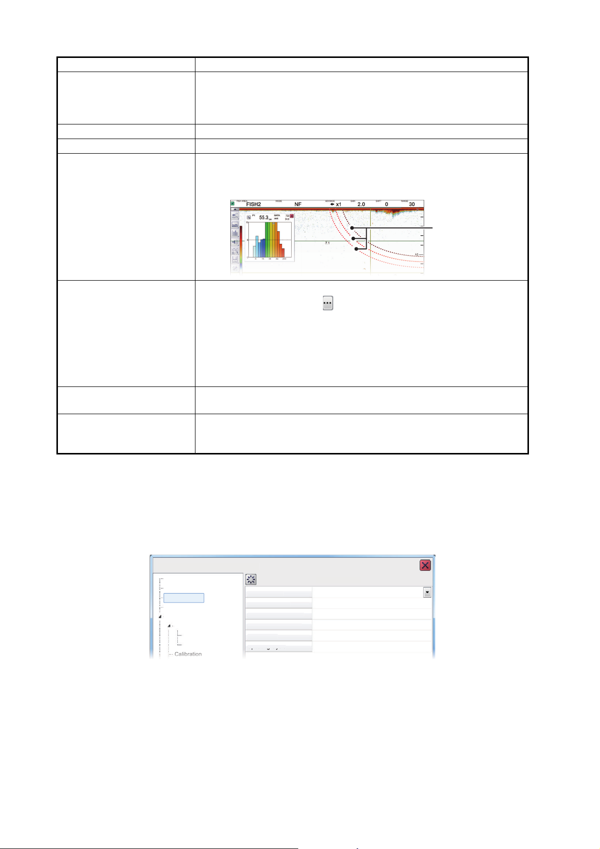
4. ADVANCED SETTINGS
Sonde marks
S
Measureme
G
y
G
D
Dist
ribu
ted
Scal
e En
d
Grap
k
Upda
p
p
ting
g
g
Cyc
y
y
le
Vertical
39
3
50%
1st
S
HF
LF
Display
Measureme
E
r
Alarm
CaliCabrat
bat
ion
o
F
Menu item Description
[Background] Change the background color. Select [Custom] to set a custom back-
ground color, or select a preset color. The [Custom] color here is not
the same as the [Hue] → [Custom] color. However, the custom color
can be set in a similar manner.
[Depth Size] Select the size at which the indication for depth is displayed.
[Depth Scale] Adjust the location at which the depth scale is displayed.
[Sonde Mark] Shows the depth of the net sonde transmitter. You can display several
sonde marks on-screen. The example below shows three sonde
marks.
[Sonde Mark Color] Set the color for the displayed sondes.
1) Select the detail icon ( ) to show the color selection pop up window.
2) Select the appropriate sonde number at the right-side of the color
selection pop up window.
3) Adjust the slide bar to change the displayed color of the sonde.
4) Select [OK] to confirm the changes, or select [Cancel] to cancel the
changes.
[Sonde Mark Width] Set the thickness at which the sonde line is displayed on-screen. Se-
lect a higher setting to increase the thickness.
[Transparency] Adjust the level of transparency for the fish graph. A higher setting in-
creases the transparency, however the graph bars, scale and indications in the graph are not made transparent.
4.4 Measurement Menu
Graph-related measurement can be set from the [Measurement] section of the [Advanced Settings] menu. For further details on each setting, see section 2.2.7.
CV-2100 [ver 02524476-xx.xx]
ounder
nt
xternal Echo Sounde
ounder
raph Displa
raph Scale End
istributed Scale Start
h Pea
nt
%
4-4
Page 81
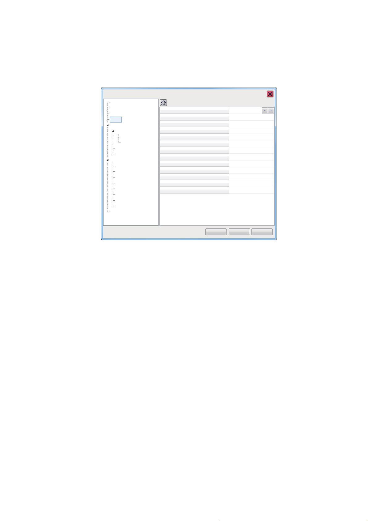
4.5 Alarm Menu
Sounder
Alarm
Bottom Start Depth
Bottom Depth Range
Fish Start Depth
Fish Depth Range
Bottom Fish Start Depth
Bottom Fish Depth Range
Temperature Alarm Trigger Temperatur
Fish Level
Medium
110.0
Temperature
Water Temperature Range
Fish Size Graph
Fish Graph Scale Threshold
Combined Alarm
2500
30
0
2500
600.0
0.1
In range
55.0
30%
Sounder
HF
LF
Display
Measurement
External Echo Sounder
Alarm
System
Range
TX/RX
TX/RX
Control Unit
Calibration
Calibration
Stabilization
Mode
Tests
Service
User Interface Settings
OK
Apply
Cancel
FCV-2100 [ver 02524476-xx.xx]
All alarms and their respective conditions can be set from the Alarm section of the [Advanced Settings] menu. For further details on setting alarms and their conditions, see
section 1.21.
4. ADVANCED SETTINGS
4.6 External Fish Finder Menu
The external fish finder can be set from the [External Fish Finder] section of the [Advanced Settings] menu.
Note 1: The [External Fish Finder] section of the [Advanced Settings] menu is available only when an external fish finder is connected correctly.
Note 2: Where [External Fish Finder Window] is set to [On] at installation, you can access external fish finder setting from a sub monitor by right-clicking a non-interactive
section of the screen. (See section 4.8.)
4-5
Page 82
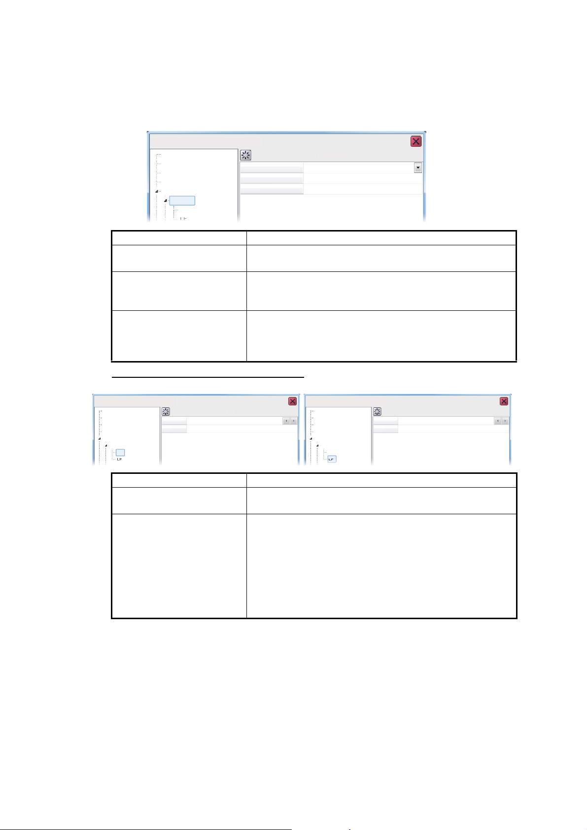
4. ADVANCED SETTINGS
S
S
r
I
S
g
Clut
ter
Auto
O
0%
S
HF
LF
Display
Meas
ent
r
Alarm
]
S
er
TVG
STC
3
0
Sounder
LF
Display
Measu
remen
t
Alarm
]
S
STC
3
0
Sound
LF
Display
Measu
remen
t
E
Alarm
F
]
4.6.1 Sounder menu
You can adjust several echo display settings for the external sounder from the [Sounder] section of the [External Fish Finder] menu. To adjust settings for the FCV-2100,
see section 4.2.
FCV-2100 [ver 02524476-xx.xx
ounder
urem
External Echo Sounde
ounder
Menu item Description
[Interference] Reject interference from other equipment. See
[Smoothing] Smooth echo presentation when enabled. Turn smooth-
[Clutter] Low intensity “speckles” caused by sediments in the wa-
ounde
nterference Rejection
moothin
n
section 1.9.
ing on when echoes appear “spotty” or “jagged”. See
section 1.10.
ter or noise, may appear over most of screen. These
speckles can be suppressed by adjusting the [Clutter].
See section 1.11.
HF/LF (high/low frequency) settings
CV-2100 [ver 02524476-xx.xx
ounder
xternal Echo Sounder
er
TVG Level
Menu item Description
[TVG Level] Adjusts the TVG (Time Varied Gain) level. See
section 1.26.
[STC] Sensitivity Time Control. Remove unwanted echoes near
the surface. Use this function when you want to see fish
near the surface clearly.
Set the STC value according to your requirement. A setting of [0] disables the STC.
Note: A high STC setting can erase fish echoes. It is recommended to watch your display when adjusting the
STC.
FCV-2100 [ver 02524476-xx.xx
ound
Level
External Echo Sounder
4-6
Page 83
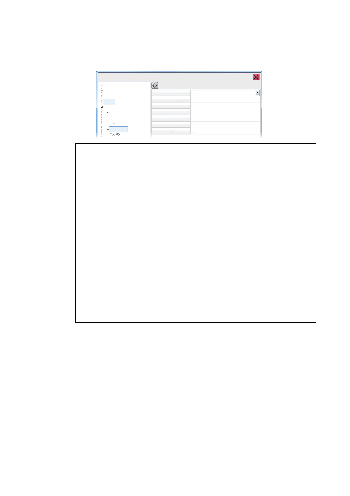
4.6.2 Calibration menu
S
Ala
rm
Z
Z
G
)
G
)
TD f
ore-af
TD p
bd
ANT
TD h
eigh
eg
g
g
t
t
0.0
Off
4.5
0
0
0.0
0.0
S
HF
LF
Display
M
ent
r
Alarm
TX/RXC
]
The external fish finder settings can be calibrated from the [Calibration] section of the
[External Fish Finder] menu. To calibrate settings for the FCV-2100, see section 4.7.5.
FCV-2100 [ver 02524476-xx.xx
ounder
easurem
External Echo Sounde
ounder
alibration
Menu item Description
[Zero Line Rejector] Turn the zero line (transmission line) on or off. When
[Zero Line Area] Adjusts the transmission line so that the transmission line
[Gain Stabilization (HF/LF)] Stabilize the gain, allowing for a clear picture when the
[TD fore-aft] Sets the fore-aft position of the external Fish Finder’s
[TD port-stbd] Sets the port-stbd position of the external Fish Finder’s
[ANT TD height]
4. ADVANCED SETTINGS
ero Line Rejection
erp Line Area
ain Stabilization (HF
ain Stabilization (LF
t
ort-st
turned [On], the transmission line disappears, which allows you to see fish echoes near the surface clearly. The
width of the transmission line changes with transducer
used and installation characteristics.
disappears when the [Zero Line Rejector] is turned on.
For a long tail, increase the value. If the transmission line
does not disappear, lower the TX power.
gain is set at a very low/high setting. This function is also
helpful in that it balances the gain between HF and LF images.
transducer. This setting is done at installation, do not
change this setting.
transducer. This setting is done at installation, do not
change this setting.
™
Sets the height of the SATELLITE COMPASS
antenna.
This setting is done at installation, do not change this setting.
4-7
Page 84
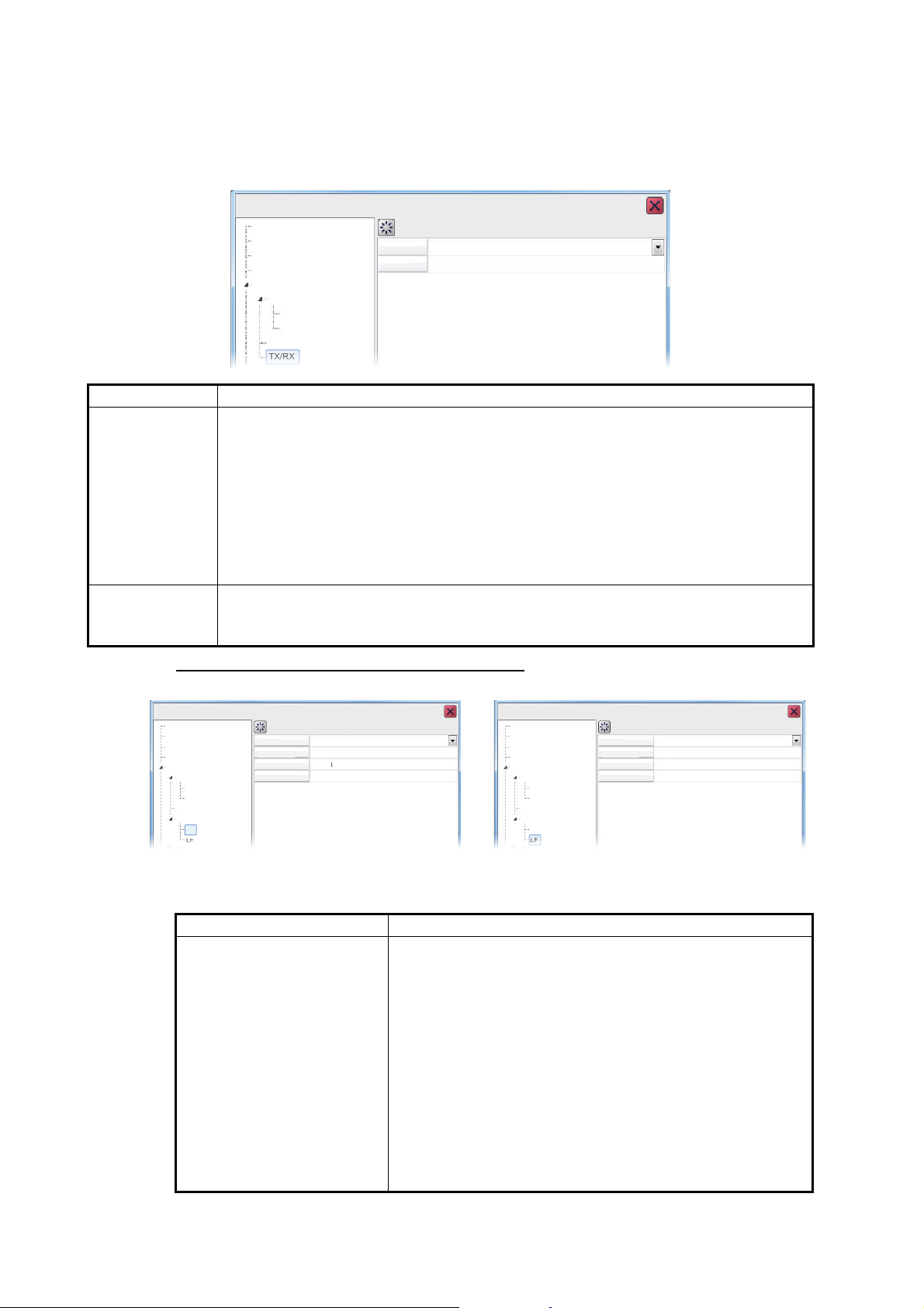
4. ADVANCED SETTINGS
S
r
S
r
lay
easurement
Alarm
TX/R
X
C
n
TX R
ate
Auto
10
F
]
S
HF
Sound
F
HF
y
easurement
Exter
nal E
S
ounde
r
Alarm
C
n
]
TX Pulse
Pul
gth
RX Band
RX Band Width
Std
1.00
a
l
0.2
S
LF
Sound
er
L
HF
D
y
easurement
Exter
nal E
S
ounde
r
Alarm
C
]
TX Pulse
Pul
gth
RX Band
RX Band Width
Std
1.00
Normal
0.2
4.6.3 TX/RX menu
Settings for the external fish finder’s transmission can be adjusted from the [TX/RX]
section of the [External Fish Finder] → [Sounder] menu.
CV-2100 [ver 02524476-xx.xx
ounde
Disp
M
External Echo Sounder
ounde
alibratio
TX Power
Menu item Description
[TX Power] When using more than one fish finder with the same frequency, in close proximity,
interference can occur. To reduce the interference, you can reduce the transmission power by lowering this setting. To disable this fish finder, set this setting to
[Off].
Depending on the connected fish finder, the settings options are as follows:
DFF3: [Off], [1] to [10]
DFF1-UHD: [Auto]*, [Off], [MIN] (Minimum), [MAX] (Maximum)
*: Select [Auto] to automatically adjust the transmission power, which produces
higher quality seabed echoes.
[TX Rate] Changes the rate at which the fish finder transmits a pulse. Adjust this setting to
erase false seabed echoes which may appear between the surface and the actual
seabed.
TX/RX
HF/LF settings for the external fish finder
FCV-2100 [ver 02524476-xx.xx
ounder
Displa
M
cho
er
L
alibratio
TX/RX
se Len
Norm
FCV-2100 [ver 02524476-xx.xx
ounder
ispla
M
cho
F
alibration
TX/RX
se Len
Note: This section of the menu is available only when DFF3 sounder is connected to
the FCV-2100.
Menu item Description
[TX Pulse] Pulse width changes according to range and shift values.
However, when long range detection or better resolution
is your objective, you can manually adjust the pulse width.
the available settings are:
• [1/4]: Higher resolution, however range is lower than
the [1/2] setting.
• [1/2]: High resolution, however range is lower then the
[Std] setting.
• [Std]: Standard (default) setting. Range and resolution
are balanced.
• [×2]: Higher range than [Std], however resolution is
lower.
• [Manual]: Adjust the pulse width manually.
4-8
Page 85
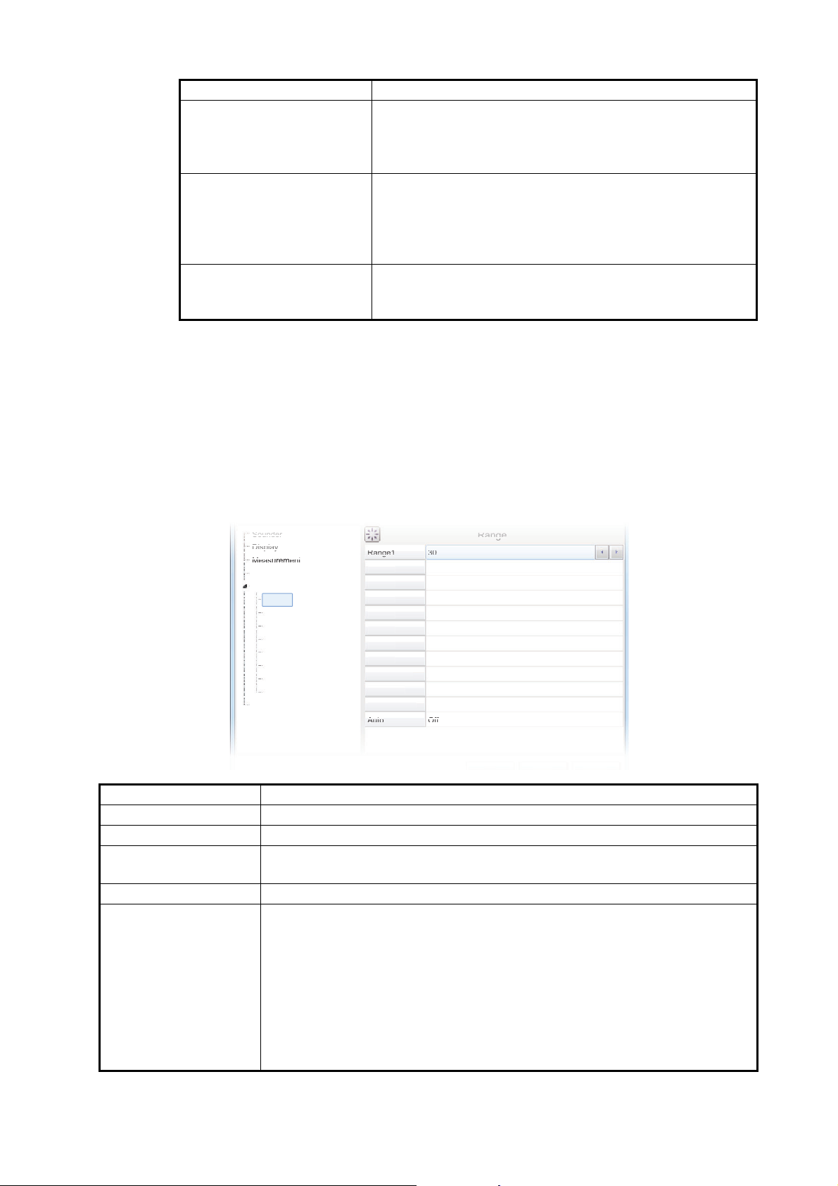
Menu item Description
Soun
der
Dispplay
y
Meas
urem
ent
Alarm
m
Rangge1
30
60
00
50
450
900
500
500
16
6
/2
Off
3
4
Range6
7
8
Z
e
Discrim Zoom
Auto
C
Cali
brat
ion
Stab
iliz
atio
n
Mode
s
S
gs
Ran
ge
g
[Pulse Length] Available only when [TX Pulse] is set to [Manual]. A low
[RX Band] Rx bandwidth is automatically set according to [TX Pulse]
[RX Band Width] Operative when [Manual] is selected at [RX Band]. A
4.7 System Menu
The [System] menu contains settings which do not require regular adjustment.
4.7.1 Range menu
4. ADVANCED SETTINGS
setting gives a higher resolution, however the range is
lowered. A high setting give a longer range, however the
resolution is lowered.
→ [Pulse Length].The [Normal] setting provides good performance. If noise is a problem switch to [Narrow]. For
better resolution, select [Wide]. [Manual] enables manual
setting of Rx band width, at [RX Band Width].
small value decreases the noise. On the other hand, a
large value gives better resolution.
The Range section of the [System] menu contains range-related settings.
Range2
Syste
Range
TX/RX
ontrol Unit
User Interface Settin
Test
ervice
Range
Range
Range5
Range
Range
oom Rang
B/L Range
1
2
1
2
1
1
Menu item Description
[Range1] to [Range8] Change the range setting for the preset ranges.
[Zoom Range] Change the range at which zoomed items appear on the display.
[B/L Range] Bottom line range. Change the range for bottom line and bottom discrimi-
nation.
[Discrim Zoom] Set the room ratio for the Discrimination Zoom function. See section 1.12.4.
[Auto] Select [Auto Range] or [Auto Shift] to enable the respective functions. Se-
lect [Off] to disable both [Auto Range] and [Auto Shift].
Note 1: Both the [Auto Range] and [Auto Shift] can only be selected indi-
vidually.
Note 2: While [Auto Range] is active, the range indication on the header
shows "AT" and the shift indication shows "N/A". Neither range nor shift can
be operated manually.
Note 3: While [Auto Shift] is active, the shift indication on the header shows
"AT". Shift cannot be operated manually. Range can be adjusted.
4-9
Page 86
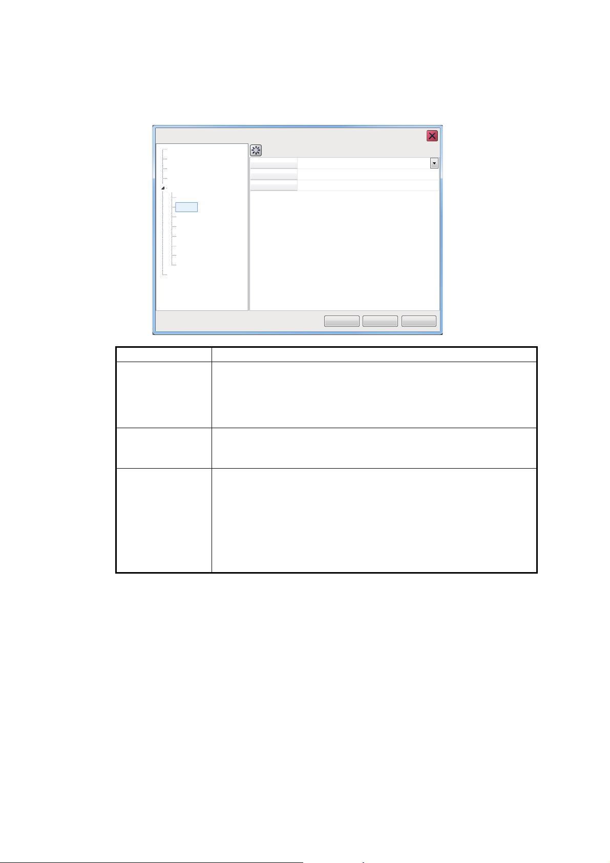
4. ADVANCED SETTINGS
Sounder
Display
Measurement
Alarm
System
Range
TX/RX
Control Unit
Calibration
Stabilization
TX Power Auto
On
20
Brightness
Bottom Search
Mode
Tests
Service
User Interface Settings
TX/RX
OK
Apply
Cancel
FCV-2100 [ver 02524476-xx.xx]
4.7.2 TX/RX menu
Settings for the FCV-2100 sounder can be changed from this menu. For external
sounders, see section 4.6.3.
Menu item Description
[TX Power] When using more than one fish finder with the same frequency, in
close proximity, interference can occur. To reduce the interference,
you can reduce the transmission power by lowering this setting. To
disable this fish finder, set this setting to [Off]. To display the seabed as best as possible, set the power level to [Auto].
[TX Rate] Changes the rate at which the fish finder transmits a pulse. Adjust
this setting to erase false seabed echoes which may appear between the surface and the actual seabed.
[Bottom Search] Show/hide the seabed. Set this to [Off] to in the following circum-
stances.
• The seabed is not visible on-screen with the current range setting. For example, the seabed is at 200 m, the on-screen range
is set to 100 m.
• When fish schools are mistaken for the seabed, resulting in unreliable depth and echo readings.
When set to [Off], the on-screen depth is displayed as "-.-".
Note: Where [Bottom Search] is set to Off, the depth indication appears as "-.-" regardless of whether the seabed is displayed or not. The following features are also affected and may not function correctly:
• Bottom Alarm
• Bottom Zoom
• Bottom Discrimination
• Auto Shift
• Hardness Graph
• Bottom Fish Alarm
• Bottom Lock
• Auto Range
• Fish Size Graph (Bottom Trace)
• White Edge
4-10
Page 87
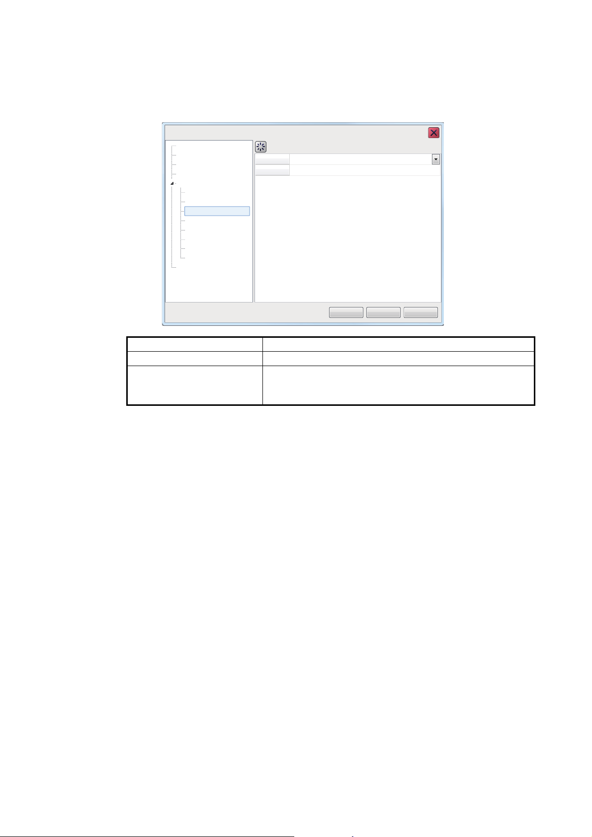
4.7.3 Control unit menu
Sounder
Display
Measurement
Alarm
System
Range
TX/RX
Control Unit
Calibration
Stabilization
Key Beep On
0
Brightness
Mode
Tests
Service
User Interface Settings
Control Unit
OK
Apply
Cancel
FCV-2100 [ver 02524476-xx.xx]
You can adjust Trackball Control Unit settings from the [Control Unit] section of the
[System] menu.
4. ADVANCED SETTINGS
Menu item Description
[Key Beep] Set to [On] or [Off] to enable or disable the key beeps.
[Brightness] Adjust the brightness for the Trackball’s power LED and
the key back-light. Set to [0] to turn the Trackball Control
Unit lights off.
4-11
Page 88
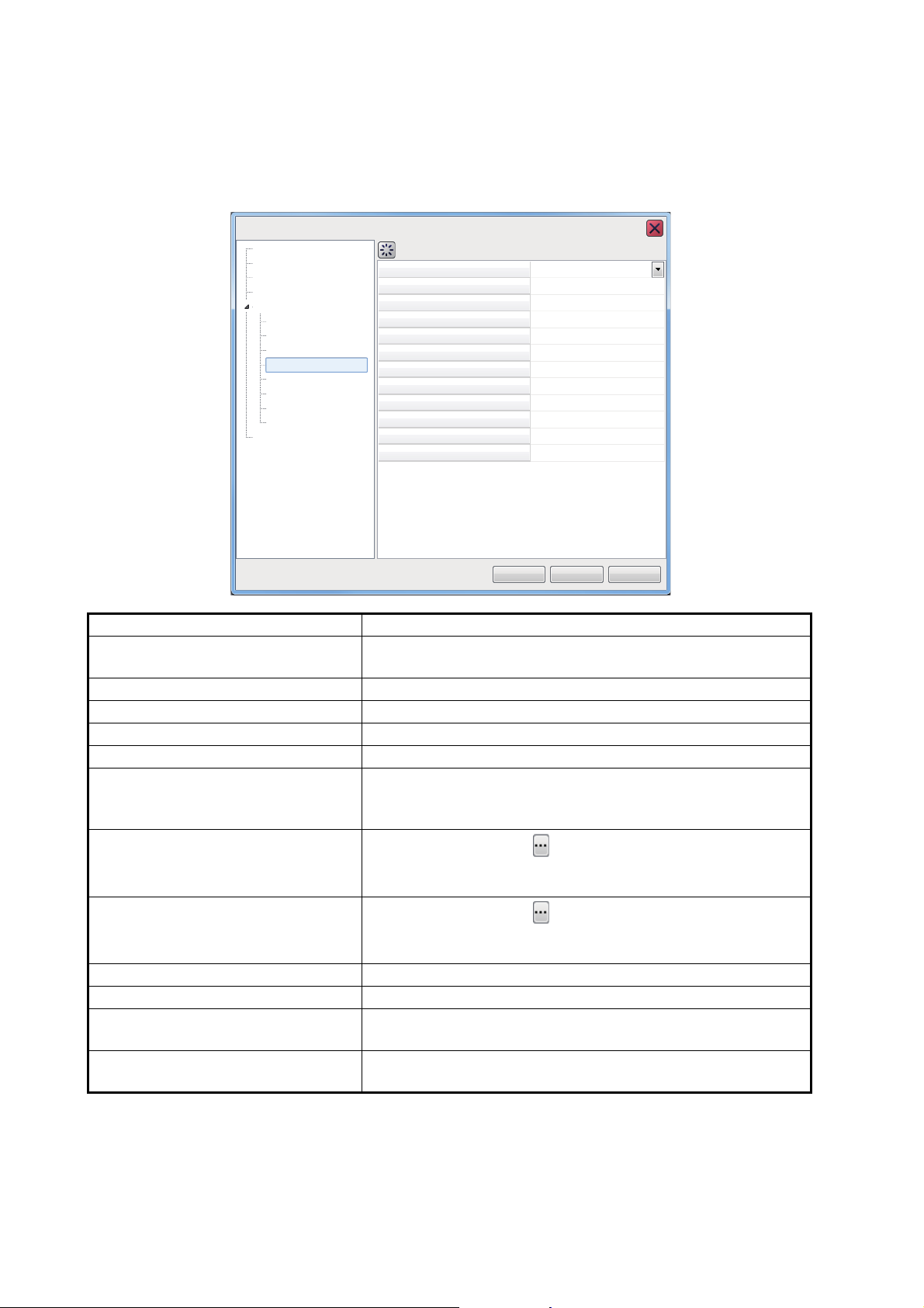
4. ADVANCED SETTINGS
4.7.4 User Interface Settings menu
You can change the units used for measurement, adjust the time difference, change
the displayed language, and change other settings from the [Setting] section of the
[System] menu.
FCV-2100 [ver 02524476-xx.xx]
Sounder
Display
Measurement
Alarm
System
Range
TX/RX
Control Unit
User Interface Settings
Calibration
Stabilization
Mode
Tests
Service
Language English
Depth
Speed
Temperature
Fish Size
Date Auto Adjust
Date Setting
Time Setting
Time Difference (Hour)
Time Difference (Minutes)
Save Destination For Screenshots
Save Intervals For Screenshots
Stabilization
ft
kn
°F
inch
On
******
******
9
0
Internal Memory
10
OK
Apply
Cancel
Menu item Description
[Language] Select the language to display the menus and on-screen in-
dications in.
[Depth] Select the unit of measurement for depth.
[Speed] Select the unit of measurement for speed.
[Temperature] Select the unit of measurement for temperature.
[Fish Size] Select the unit of measurement for fish size.
[Date Auto Adjust] To automatically adjust the date and time based on the data
from a connected navigational aid, set this setting to [On].
Select [Off] to manually adjust date and time.
[Date Setting]
Select the detail icon ( ) to show the date adjustment pop
up window. Adjust the date as required, then select [OK] to
apply the changes. Select [Cancel] to cancel the changes.
[Time Setting]
Select the detail icon ( ) to show the time adjustment pop
up window. Adjust the time as required, then select [OK] to
apply the changes. Select [Cancel] to cancel the changes.
[Time Difference (Hour)] Apply an offset, in hours, to UTC time.
[Time Difference (Minutes)] Apply an offset, in minutes, to UTC time.
[Save Destination For Screenshots] Select the save destination for screenshots (still images).
See section 3.1.1.
[Save Intervals For Screenshots] Select the interval timing for taking repeated screenshots.
section 3.1.3.
4-12
Page 89
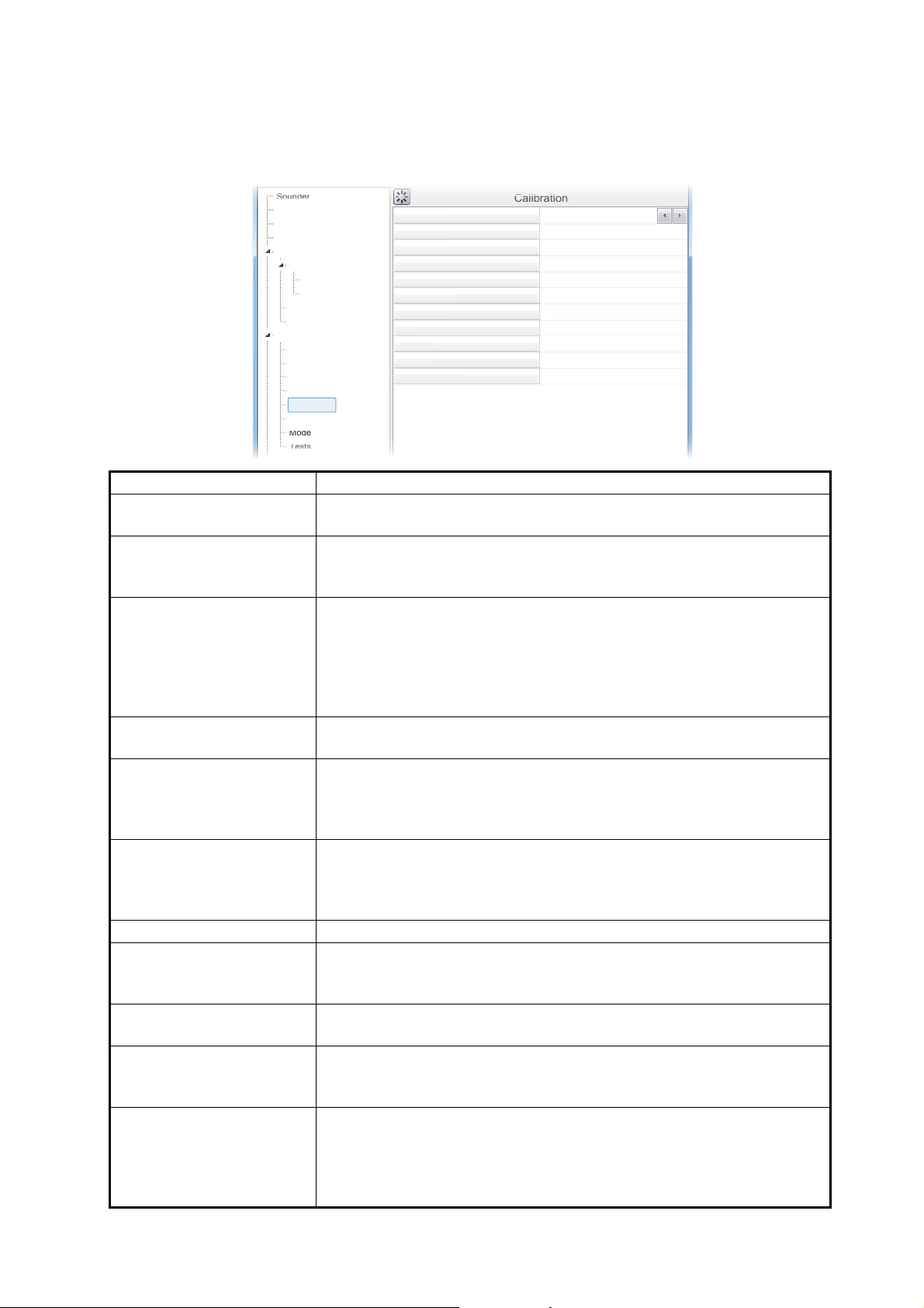
4.7.5 Calibration menu
Soun
der
Cal
ibr
ati
on
S
T
ure
B
l
P
n
Z
n
Zero Line Area
Zero
Lin
e Fi
ll
G
ADJ
F
C
ing
1500.0
0.0
0.0
0.0
0.0
Off
Off
4.50
0
0
Soun
der
HF
Disp
lay
M
E
r
Alarm
System
Rang
TX/R
X
TX/
C
C
C
S
n
Mode
Test
s
U
You can calibrate (offset) the speed of sound, water temperature and other information from [Calibrate] section of the [System] menu.
4. ADVANCED SETTINGS
easurement
xternal Echo Sounde
alibration
RX
e
ontrol Unit
ser Interface Settings
alibration
tabilizatio
ound Speed
emperat
ottom Leve
osition to Start Bottom Detectio
ero Line Rejectio
Draft
ain
ish Size
alibration Sett
Menu item Description
[Sound Speed] Adjust the sound velocity of the TX/RX signal if the depth indication is
incorrect, often caused by water temperature or salinity.
[Temperature] If the water temperature indication is wrong, you can correct it here.
For example, if the actual temperature is 2°C higher than the temperature displayed on screen, set the offset to [+2°C].
[Bottom Level] In the default bottom level setting [0], the equipment judges consecu-
tive strong echoes to be bottom echoes. If, in that setting, the depth
indication is unstable, adjust the bottom level. If vertical lines extend
upward from the bottom echo in the bottom lock display, lower the bottom level to erase the vertical lines. If the level is too low, however, it
may be difficult to distinguish bottom fish from the bottom echo.
[Position to Start Bottom
Set the depth threshold at which the seabed is detected.
Detection]
[Zero Line Rejector] Turn the zero line (transmission line) on or off. When turned on, the
transmission line disappears, which allows you to see fish echoes
near the surface clearly. The length of the transmission line changes
with transducer used and installation characteristics.
[Zero Line Area] This function adjusts the transmission line so that the transmission line
disappears when the menu item [Zero Line Rejection] is turned on. For
a long tail, increase the value. If the transmission line does not disap-
pear, lower the TX power.
[Zero Line Fill] Turn off to see fish echoes within 1 m from the surface.
[Draft] The default depth display shows the distance from the transducer. If
you would rather show the distance from the sea surface, set your
ship's draft. The draft line for HF and LF can be set respectively.
[Gain ADJ] If the gain is too high or too low, or the gain for the low and high fre-
quencies appears unbalanced, you can compensate it here.
[Fish Size] Compensate for incorrect fish size indications. A positive value in-
creases compensation, a negative value decreases compensation.
For example [+50] increases the size indication by 1.5 times.
[Calibration Setting] Set the target strength (echo strength for individual fish). If a calibra-
tion sphere was used, its value is shown. This value may be fine tuned.
For further details, see section 2.2.8.
The larger the calibration figure the longer the length of the individual
fish, even if the received signal is the same strength.
4-13
Page 90
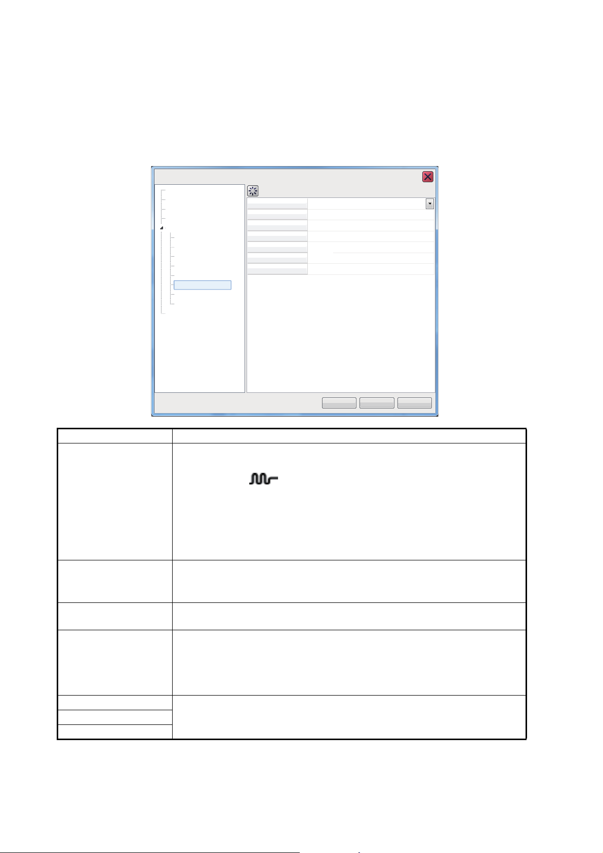
4. ADVANCED SETTINGS
4.7.6 Stabilization menu
You can adjust for heave in the [Stabilization] section of the [System] menu.
Note 1: This function require connection to a SATELLITE COMPASS
™
inactive if data from the SATELLITE COMPASS
is interrupted or lost.
™
and becomes
Note 2: This function is unavailable if [TX Triggering] is set to [On] at installation.
FCV-2100 [ver 02524476-xx.xx]
Sounder
Display
Measurement
Alarm
System
Range
TX/RX
Control Unit
User Interface Settings
Calibration
Stabilization
Mode
Tests
Service
Stabilization Off
Stabilization Sensor
Delay Time
Stabilization Area
TD fore-aft
TD port-stbd
ANT TD height
Stabilization
SC-50
250
20
0.0
0.0
0.0
OK
Apply
Cancel
Menu item Description
[Stabilization] Turn heaving compensation on or off. Turn it on when seas are rough, to
get stable echoes, regardless of sea conditions. When turned on, the stabilization icon ( ) appears in the [Picture Advance] section of the
header.
Note: Where data from the SATELLITE COMPASS™ is interrupted or lost,
the stabilization icon is overlaid with a cross to indicate that it is not in use.
When data from the SATELLITE COMPASS
™
is received again, the cross
is removed.
[Stabilization Sensor]
Set at installation. Indicates the SATELLITE COMPASS
™
connected to
the FCV-2100.
Do not change this setting.
[Delay Time] Set at installation. Available only when [Stabilization Sensor] is set to
[Manual]. Do not change this setting.
[Stabilization Area] When heaving exceeds the value set here, stabilization is stopped and the
stabilization icon at the top of the screen is displayed with an “X”, indicating
it has stopped. However, the setting for [Stabilization] is kept [On]. When
heaving is once again less than the value set here, stabilization is restarted and the “X” disappears.
[TD fore-aft] Set at installation.Indicates the location and height of the SATELLITE
[TD port-stbd]
[ANT TD height]
COMPASS
Do not change these settings.
™
antenna.
4-14
Page 91
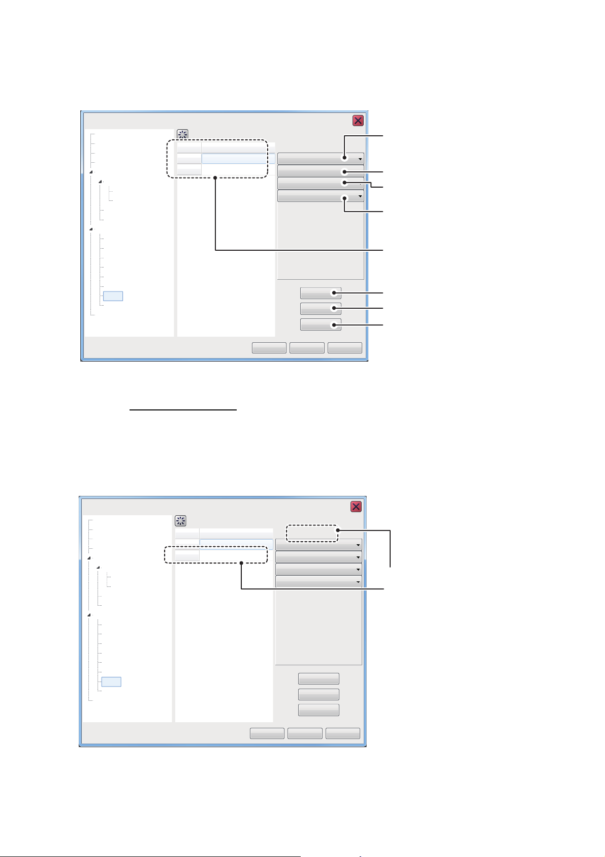
4.7.7 Mode menu
Sounder
Mode
Sounder
HF
LF
Display
Measurement
External Echo Sounder
No
1
2
Mode
NF
ZM-NF
Alarm
System
Range
TX/RX
TX/RX
Control Unit
Calibration
Calibration
Stabilization
Mode
Tests
Service
User Interface Settings
OK
Apply
Add
NF
Normal
Not selected
Not selected
Not selected
Refresh
Delete
Cancel
FCV-2100 [ver 02524476-xx.xx]
Items selected for the current
display mode are abbreviated
and shown in these two locations.
You can “split” the display screen from the [Mode] section of the [System] menu. This
allows you to display different information across two or more sections of the display.
FCV-2100 [ver 02524476-xx.xx]
Sounder
Display
Measurement
Alarm
External Echo Sounder
Sounder
HF
LF
Calibration
TX/RX
System
Range
TX/RX
Control Unit
User Interface Settings
Calibration
Stabilization
Mode
Tests
Service
No
1
2
Mode
NF
ZM-NF
Mode
Normal
Not selected
Not selected
Not selected
NF
Add
Refresh
Delete
4. ADVANCED SETTINGS
Contents of screen1
(Fixed at [Normal]).
Contents of screen2
Contents of screen3
Contents of screen4
Mode list. The currently selected
mode is highlighted in blue.
Select to add a new mode.
Select to refresh the mode list.
Select to delete the current mode.
OK
Apply
Cancel
For details on split screen modes, see "SCREEN LAYOUTS" on page AP-5.
How to add a mode
You can add up to 8 modes. To add a mode, do the following:
1. Select the appropriate contents drop-down from the right-side of the menu. The
contents are listed in line with their respective modes, as indicated in the figure
above.
You can select up to four items to be displayed for each mode.
4-15
Page 92
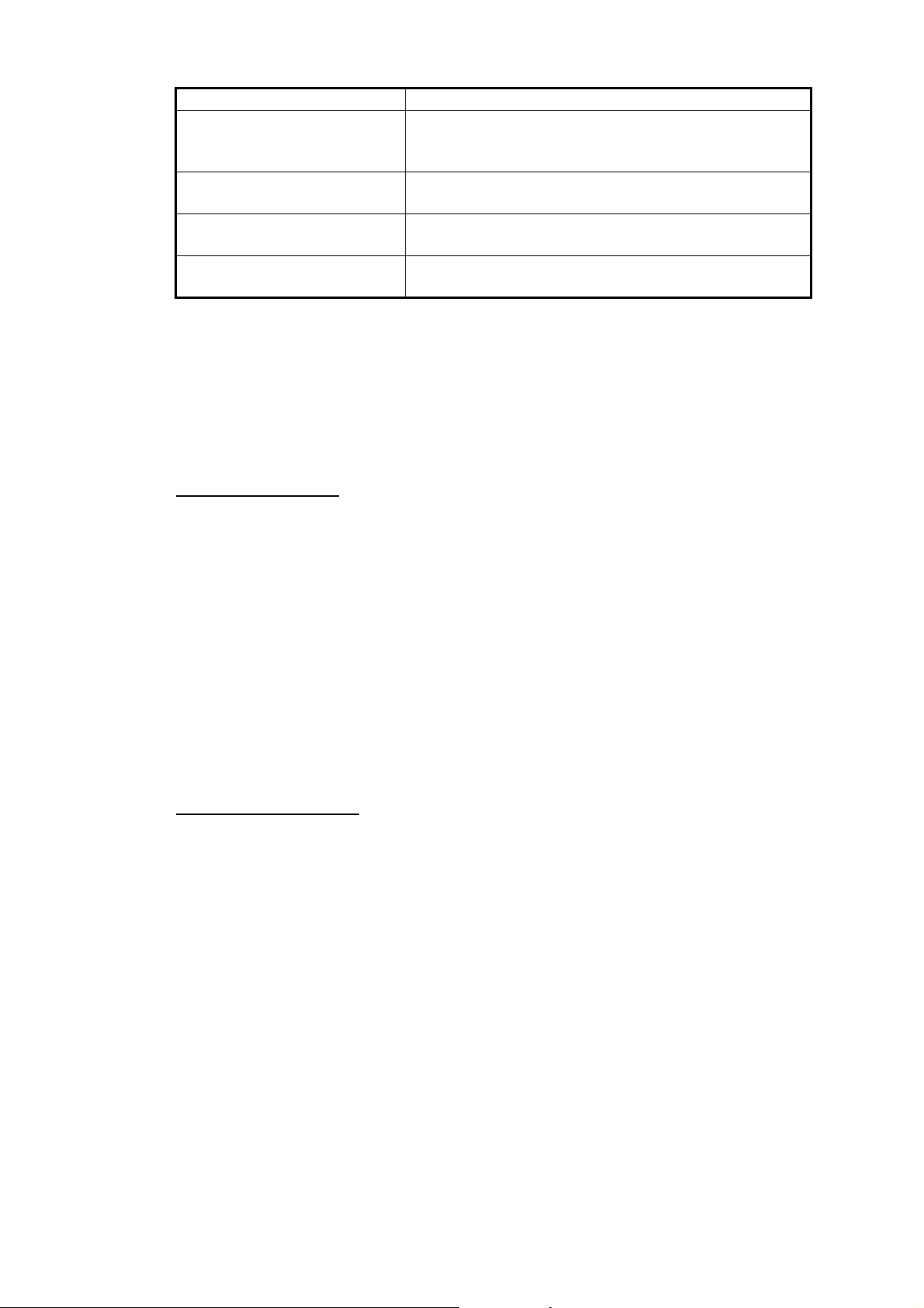
4. ADVANCED SETTINGS
Menu item Description
[Not Selected] No split screen is displayed. If the second item is set to
[Zoom] Displayed as "ZM" in the mode list. Adds the zoomed
[High Frequency (External)]* Displayed as "HE" in the mode list. Adds the external
[Low Frequency (External)]* Displayed as "LE" in the mode list. Adds the external
*: These menu items are displayed only when [External Fish Finder Window] is set
to [Off] at installation.
2. Select the [Add] button, near the bottom-right of the menu. The new mode is added to the mode list.
3. Select [Apply] to apply the changes and delete or edit a different mode. Select
[OK] to apply the changes and close the menu. Select [Cancel] to cancel any
changes made and close the menu.
How to edit a mode
[Not Selected], the third and fourth items show no options.
area to the split screen.
sounder’s high frequency images to the split screen.
sounder’s low frequency images to the split screen.
You can edit the contents of a display mode at any time. To edit a mode, do the following:
1. With the [Mode] menu displayed, select the display mode you wish to edit, from
the mode list.
2. At the right-side of the menu window, select the contents you wish to change. A
drop-down list of options appears.
3. Select the appropriate item, referring to the table in “How to add a mode” on the
previous page.
4. Select [Apply] to apply the changes and edit a different mode. Select [OK] to apply
the changes and close the menu. Select [Cancel] to cancel any changes made
and close the menu.
How to delete a mode
1. With the [Mode] menu displayed, select the display mode you wish to delete, from
the mode list.
2. At the bottom-right of the window, select [Delete].
3. Select [Apply] to apply the changes and delete or edit a different mode. Select
[OK] to apply the changes and close the menu. Select [Cancel] to cancel any
changes made and close the menu.
4-16
Page 93
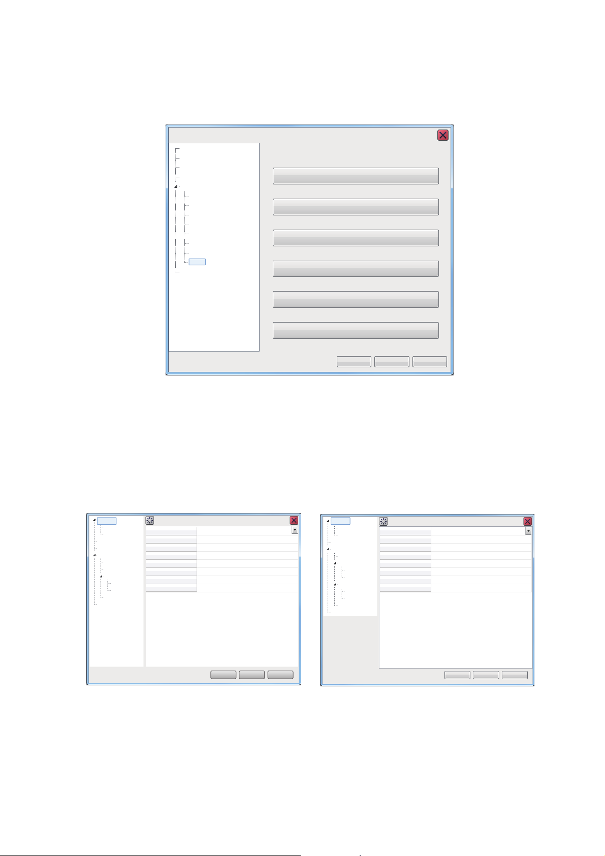
4.7.8 Tests menu
Sounder
Display
Measurement
Alarm
System
Service
Range
TX/RX
Control Unit
Setting
Calibration
Mode
Stabilization
Tests
Tests
Maintenance Information
Communication Port Monitor
Log Output
Control Unit Test
LCD Test
TX
OK
Apply Cancel
FCV-2100 [ver 0252446-xx.xx]
DFF1-UHD settings menu DFF3 settings menu
HF
LF
HF
LF
HF
LF
System
Range
Range
Shift
Interference Rejection
Color Erase
White Marker
Pic. Advance
Smoothing
Clutter
250
0
Auto
0%
Off
x1
On
0%
TX/RX
Calibration
Stabilization
Service
OK
Apply
Cancel
Sounder
Sounder
Display
OK
Apply
Cancel
Range
Shift
Interference Rejection
Color Erase
White Marker
Pic. Advance
Smoothing
Clutter
250
0
Auto
0%
Off
x1
On
0%
Sounder
HF
LF
HF
LF
System
Range
TX/RX
Calibration
Stabilization
Service
Sounder
Display
Measurement
Maintenance information, diagnostic tests and other tools are found in the [Tests] section of the [System] menu.
4. ADVANCED SETTINGS
4.8 External Fish Finder Window
For details on this menu, see section 5.7.
For configurations where [External Fish Finder Window] is set to [On] at installation,
the external fish finder’s settings can be adjusted from the sub display. To access the
external fish finder settings, right-click a non-interactive section of the screen.
4-17
Page 94
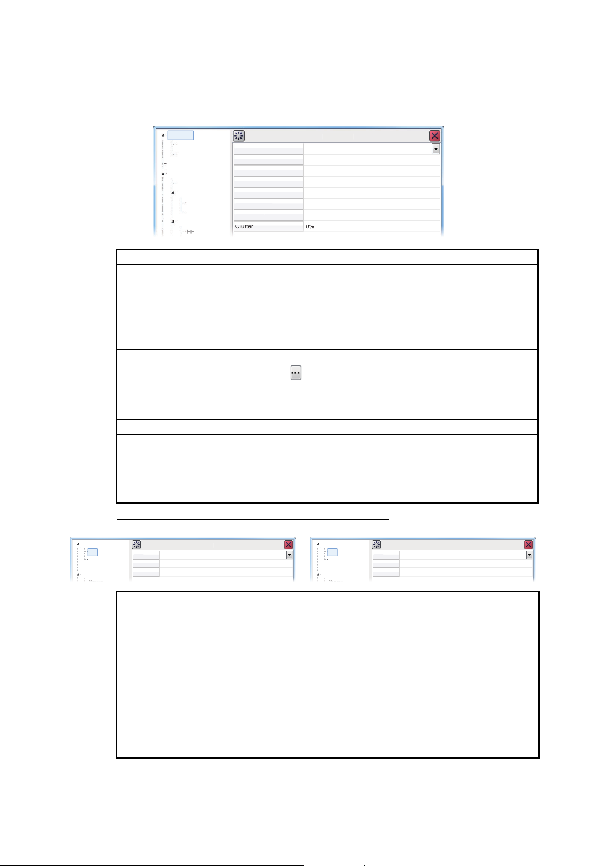
4. ADVANCED SETTINGS
HF
LF
HF
LF
m
Range
Range
Shift
Interf
n
Col
e
White Marke
Pi
e
S
thing
Clu
tte
r
250
0
Auto
0%
Off
x1
O
0%
Cal
ibr
ationS
r
S
r
Display
F
m
Gai
TVG L
l
STC
2.0
5
0
S
er
HF
ay
F
Sy
m
Gain
TVG L
l
STC
2.0
5
0
S
LF
D
y
4.8.1 Sounder menu
Settings for external sounders (DFF3 and DFF1-UHD) can be found in the [Sounder]
section of the [External Fish Finder] menu.
ounde
Syste
TX/RX
erence Rejectio
or Eras
r
c. Advanc
moo
ounde
n
Menu item Description
[Range] Change the range setting for the preset ranges. See
section 1.8.
[Shift] Shift the displayed echo are up or down. See section 1.7.
[Interference] Reject interference from other equipment. See
section 1.9.
[Color Erase] Erase unwanted noise. See section 1.25.
[White Marker] Displays selected echoes in white color. Select the detail
icon ( ) to show the color selection pop up window.
Select the echo color to be displayed as white, then select
[OK].
To cancel all changes, select [Cancel].
[Pic. Advance] Set the [Picture Advance] speed. See section 1.5.
[Smoothing] Smooth echo presentation when enabled. Turn smooth-
ing on when echoes appear “spotty” or “jagged”. See
section 1.10.
[Clutter] Remove unwanted echoes (sediment, etc.). See
section 1.11.
ound
Displ
Syste
HF/LF (High Frequency/Low Frequency) settings
H
n
eve
Menu item Description
[Gain] Adjust the gain level. See section 1.6.
[TVG Level] Time Varied Gain. Adjusts the TVG level. See
section 1.26.
[STC] Sensitivity Time Control. Remove unwanted echoes near
the surface. Use this function when you want to see fish
near the surface clearly.
Set the STC value according to your requirement. A set-
ting of [0] disables the STC.
Note: A high STC setting can erase fish echoes. It is rec-
ommended to watch your display when adjusting the
STC.
ounder
ispla
H
eve
ste
4-18
Page 95
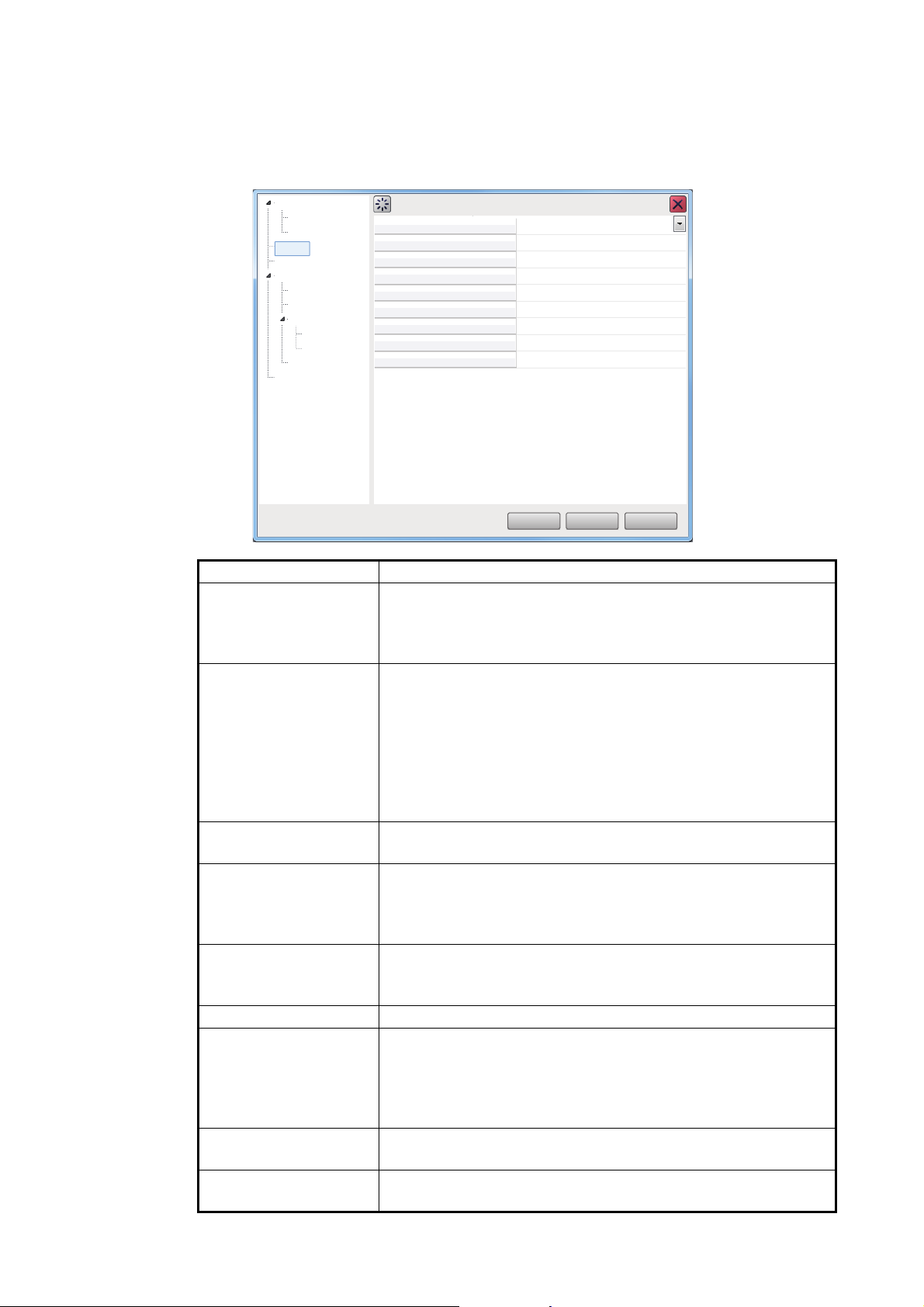
4.8.2 Display menu
You can adjust the display settings for the external fish finder from the [Display] section of the [External Fish Finder] menu.
4. ADVANCED SETTINGS
Sounder
HF
LF
Display
Measurement
System
Range
TX/RX
Calibration
HF
LF
Stabilization
Service
Mode
Display Division
Colors
Hue
Background
Depth Size
Depth Scale
Bottom Discrim
Bottom Discrimination Legend
Display
LF/HF
Vertical
64
Normal
White
Normal
Right
Probability
Off
OK
Apply
Cancel
Menu item Description
[Mode] Select the display mode for the external fish finder.
• [HF/HF]: High and Low frequency.
• [HF]: High frequency only.
• [LF]: Low frequency only.
[Display Division] Select the method in which the display is divided. This option
is only available when [Mode] is set to [HF/LF].
• [Horizontal]: The dividing line runs horizontally (left to right)
and the display shows high frequency input at the top of the
screen.
• [Vertical]: The dividing line runs vertically (top to bottom)
and the display shows high frequency input to the left of the
screen.
[Colors] Select the number of colors (16 or 64) available for the [Color
Bar] and echo colors.
[Hue] Select a hue to suit the ambient light.
• [Normal]: Use the default hue settings.
• [Hue1] to [Hue6]: Use the custom hue settings for the respective selection.
[Background] Select the background color for the display. Some indications
will automatically change color according to the color selected
here.
[Depth Size] Select the size of the depth text indication.
[Depth Scale] Select the location at which the depth scale is displayed.
• [Off]: Hide the depth scale.
• [Right]: Show the scale at the far right-hand side of the
screen.
• [Center]: Show the scale at the center of the screen.
[Bottom Discrimination]
[Bottom Discrimination
Legend]
Select the method of bottom discrimination (see
section 1.20.3).
Show/hide the bottom discrimination legend. (See
section 1.20.3.)
4-19
Page 96
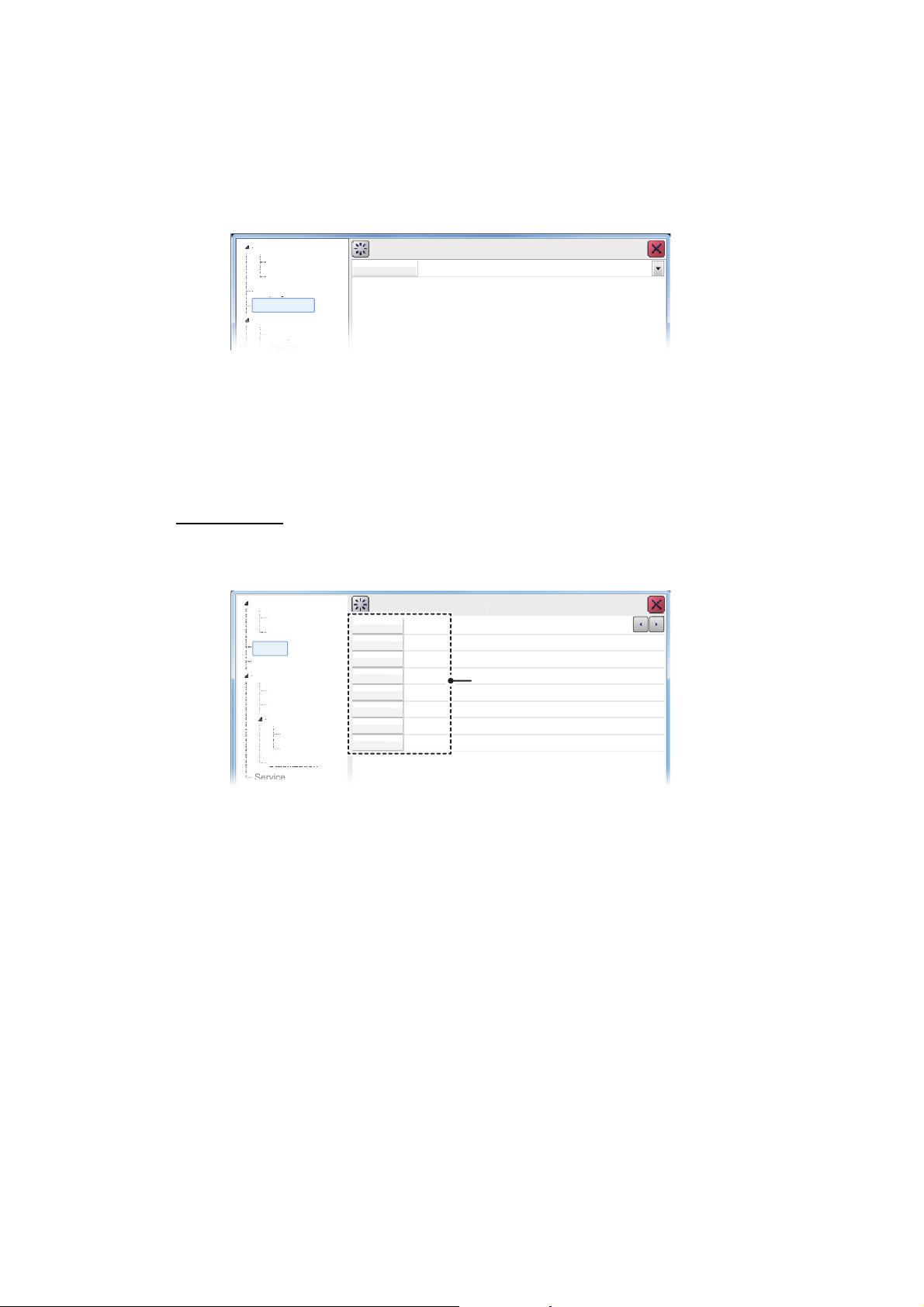
4. ADVANCED SETTINGS
R
1
R
2
R
3
Range4
R
5
R
6
R
7
R
8
3060100
250
450
900
0
2500
R
e
LF
HF
LF
System
R
C
n
Sta
bil
iza
tio
n
Ser
vic
e
S
r
Display
M
4.8.3 Measurement menu
The [Measurement] menu is available only when an ACCU-FISH™ compatible transducer is connected.
Use this menu to activate/deactivate the ACCU-FISH
™
feature.
Sounder
HF
LF
Display
Measurement
System
Range
See section 1.20.2 for how to use this feature.
4.8.4 System menu
The [System] menu contains settings for items which do not require regular adjustment or change.
Range menu
Change any of the eight available the preset ranges.
ounde
easurement
ange
TX/RX
alibratio
ACCU-FISH Off
ange
ange
ange
ange
ange
ange
150
ange
Measurement
ang
Range presets for
external fish finder
4-20
[Range 1] to [Range 8] can be adjusted to suit your preferences.
Page 97
4. ADVANCED SETTINGS
S
TX Pulse
LF
Std
1.00
Normal
0
Pul
gth
RX Band
RX Band Width
HF
LF
Display
Rang
S
r
TX Pulse
HF
Std
00
Normal
0
Pul
gth
RX Band
RX Band Width
HF
LF
Display
Rang
TX/RX menu
The [TX/RX] menu contains settings for pulse transmission and receipt. Depending on
your vessel’s configuration, some menu items may not be available. See the lists below for more details.
Menu item Description
[TX Power] Adjusts the output power of the transducer. Where fish finders or
other equipment causes interference, you can adjust the output
power level to help reduce, or eliminate, the interference. You can
also disable transmission completely by selecting the [Off] option.
The setting options are different for DFF3 and DFF1-UHD:
DFF3: [Off], [1] to [10]
DFF1-UHD: [Auto]*, [Off], [MIN] (Minimum), [MAX] (Maximum)
*: Select [Auto] to automatically adjust the transmission power,
which produces higher quality seabed echoes.
[TX Rate] Adjusts the transmission rate for the transducer. When in shallow
waters second reflection echoes may appear between the surface
and actual bottom echo. In this case, lower the TX rate level. Use
a high rate for fast speed; a slow rate for slow speed.
TX/RX menu (HF/LF settings)
ounde
System
TX/RX
se Len
e
1.
.2
ounder
System
TX/RX
se Len
e
.2
Note: These settings are only available when connected to a DFF3. See the table below for menu items and descriptions:
Menu item Description
[TX Pulse] Pulse width changes according to range and shift values. However,
when long range detection or better resolution is your objective,
you can manually adjust the pulse width. the available settings are:
• [1/4]: Higher resolution, however range is lower than the [1/2]
setting.
• [1/2]: High resolution, however range is lower then the [Std] setting.
• [Std]: Standard (default) setting. Range and resolution are balanced.
• [×2]: Higher range than [Std], however resolution is lower.
• [Manual]: Adjust the pulse width manually.
[Pulse Length] Available only when [TX Pulse] is set to [Manual]. A low setting
gives a higher resolution, however the range is lowered. A high setting give a longer range, however the resolution is lowered.
[RX Band] Rx bandwidth is automatically set according to [TX Pulse] → [Pulse
Length].The [Normal] setting provides good performance. If noise
is a problem switch to [Narrow]. For better resolution, select [Wide].
[Manual] enables manual setting of Rx band width, at [RX Band
Width].
[RX Band Width] Operative when [Manual] is selected at [RX Band]. A small value
decreases the noise. On the other hand, a large value gives better
resolution.
4-21
Page 98
4. ADVANCED SETTINGS
LF
HF
m
Z
Zero Line Area
Off
4.5
Draft
0.0
Fish Si
0
S
d
1500.0
C
Sou
nde
r
C
n
Display
HF
LF
HF
LF
Sy
Rang
Bottom Level
Gain ADJ
0
0
n
S
r
Display
HF
LF
HF
LF
Sy
m
Range
Bottom Level
Gain ADJ
0
0
TX/RX
S
r
Display
Calibration menu
Use the Calibration menu to apply offsets for the external fish finder.
alibratio
ero Line Rejection
Syste
Range
TX/RX
alibration
ze
ound Spee
Menu item Description
[Zero Line Rejection]
Turn the zero line (transmission line) on or off. When turned [On],
the transmission line disappears, which allows you to see fish
echoes near the surface clearly. The width of the transmission line
changes with transducer used and installation characteristics.
[Zero Line Area] Adjust the transmission line so that the transmission line disap-
pears when the [Zero Line Rejector] is turned on. For a long tail, increase the value. If the transmission line does not disappear, lower
the TX power.
[Draft] The default depth display shows the distance from the transducer.
If you would rather show the distance from the sea surface, set your
ship's draft. The draft line for HF and LF can be set respectively.
[Fish Size] Compensate for incorrect fish size indications. A positive value in-
creases compensation, a negative value decreases compensation.
For example [+50] increases the size indication by 1.5 times.
[Sound Speed] Adjust the sound velocity of the TX/RX signal if the depth indication
is incorrect, often caused by water temperature or salinity.
Calibration menu - HF/LF settings
ounde
ste
Calibration
Menu item Description
[Bottom Level] In the default bottom level setting [0], the equipment judges con-
secutive strong echoes to be bottom echoes. If, in that setting, the
depth indication is unstable, adjust the bottom level. If vertical lines
extend upward from the bottom echo in the bottom lock display,
lower the bottom level to erase the vertical lines. If the level is too
low, however, it may be difficult to distinguish bottom fish from the
bottom echo.
[Gain ADJ] If the gain is too high or too low, or the gain for the low and high
frequencies appears unbalanced, you can compensate it here.
ounde
stem
TX/RX
Calibratio
e
4-22
Page 99
4. ADVANCED SETTINGS
S
r
HF
LF
y
Rang
m
C
n
Stab
iliz
atio
n
Stabilization
O
SC-50
50
0.0
0.0
0.0
S
n
Stabilizati
Delay Time
TD fore-aft
TD port-stbd
ANT TD height
ServSeice
ce
Stabilization menu
You can adjust for heave on the external fish finder from the [Stabilization] menu. This
function require connection to a SATELLITE COMPASS
™
data from the SATELLITE COMPASS
is interrupted or lost.
™
and becomes inactive if
ounde
Displa
Syste
on Sensor
e
TX/RX
H
alibratio
H
tabilizatio
ff
2
Menu item Description
[Stabilization] Turn heaving compensation on or off. To get stable seabed echoes
regardless of sea conditions, turn [Stabilization] on when seas are
rough.
[Stabilization
Sensor]
Set at installation. Indicates the SATELLITE COMPASS
ed to the FCV-2100. Do not change this setting.
™
connect-
[Delay Time] Set at installation. Available only when [Stabilization Sensor] is set
to [Manual]. Do not change this setting.
[TD fore-aft],
[TD port-stbd],
Set at installation. Indicates the location and height of the SATEL-
LITE COMPASS
™
antenna. Do not change these settings.
[ANT TD height]
4-23
Page 100

4. ADVANCED SETTINGS
This page is intentionally left blank.
4-24
 Loading...