

Page 1
FAR-2xx7 SERIES MARINE RADAR
Operator’s Guide
The purpose of this Ope r ator's Guide is to provid e the basic ope r ating procedures for this equipment. F or
more detailed information, see the Operator's Manual. This manual describes operating procedures using
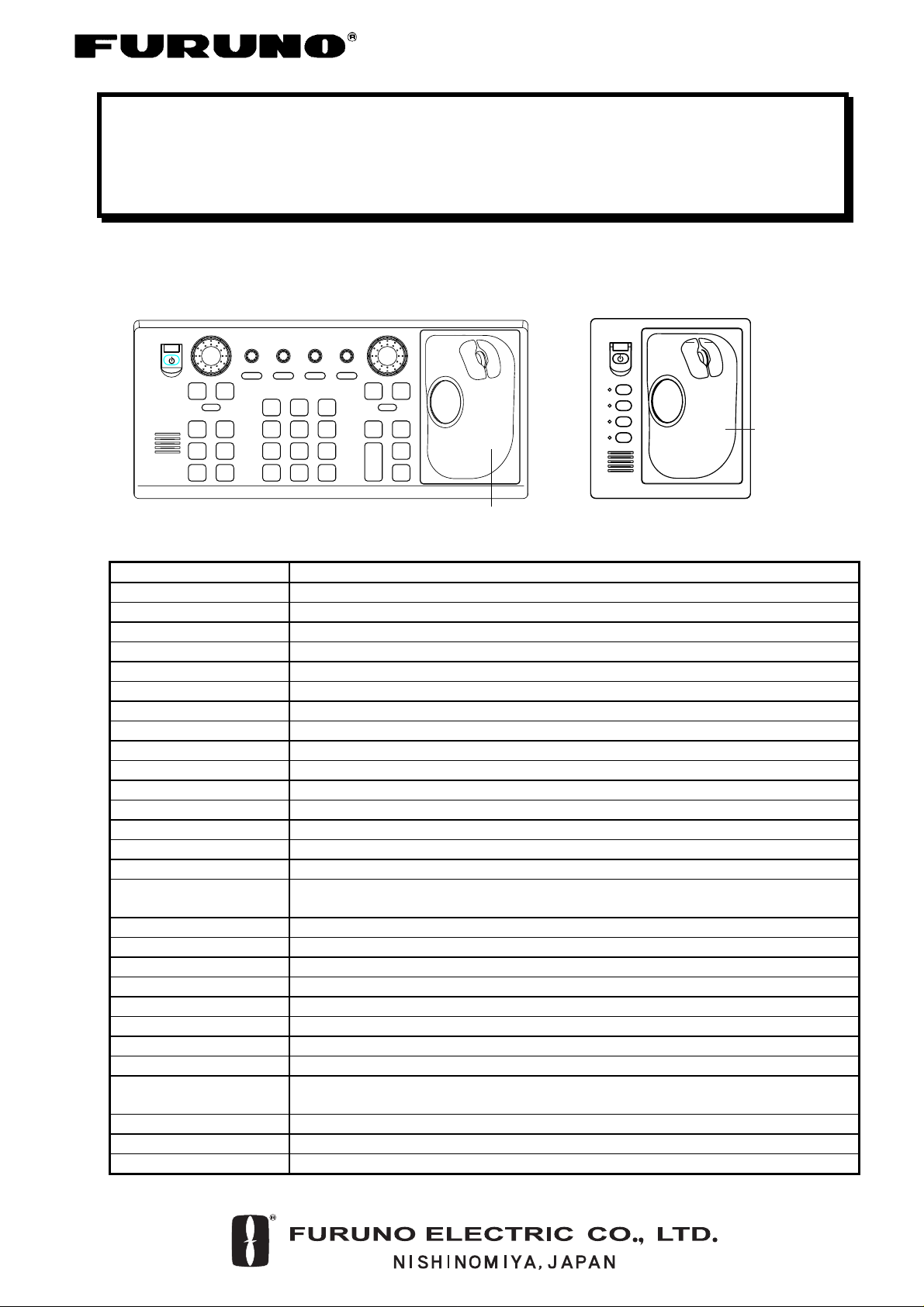
the trackball module, since it is common to both types of control units.
21
EBL
HL
OFFSET
OFF
45
CU/TM
OFF
CENTER
RESET
78
VECTOR
VECTOR
MODE
TIME
0
CANCEL
TRAILS
BRILL
A/C SEAA/C RAIN
MODE
INDEX
LINE
TARGET
LIST
ENTER
MARK
GAIN
3
6
9
MENU
RANGE
ON
OFF
VRM
ACQ
TARGET
+
DATA
TARGET
-
CANCEL
F1
F2
F3
F4
Trackball
Module
Trackball
Module
OFFF2ON
F1
F3 F4
ALARM
ACK
BRILL
EBL
STBY
TX
RCU-014 RCU-015
Control Description
POWER Turns the system on and off.
EBL and VRM controls Adjust EBL and VRM, respectively.
EBL ON, EBL OFF Turns the EBLs on and off, respectively.
VRM ON, VRM OFF Turns the VRMs on and off, respectively
F1-F4 Execute menu short cut assigned.
ALARM ACK Silences audible alarm.
STBY TX Toggles between stand-by and transmit.
BRILL Adjusts screen brilliance of FURUNO-supplied monitor.
A/C RAIN Suppresses rain clutter.
A/C SEA Suppresses sea clutter .
GAIN Adjusts sensitivity of the radar receiver.
HL OFF Temporarily erases the heading line while pressed.
EBL OFFSET Enables, disables the EBL offset. Switches coordinate polarity (menu operation).
MODE Chooses presentation mode.
OFF CENTER Shifts own ship position.
CU/TM RESET Moves own ship position in 75% radius in stern direction.
Resets the heading line to 0° in course-up and true motion modes.
INDEX LINE Turns index lines on and off.
VECTOR TIME Chooses vector time (length).
VECTOR MODE Chooses vector mode, relative or true.
TARGE T LIST Displays ARP target list.
CANCEL TRAILS Cancels all target trails. In menu operation it clears line of data.
BRILL/O Chooses color scheme.
ENTER MARK Enters marks; terminates keyboard input.
MENU Opens and closes the MAIN menu; closes other menus.
ACQ - Acquires a target for ARP.
- Changes a sleeping AIS target to an activated one.
RANGE Chooses radar range.
TARGET DATA Displays target data for ARP or AIS target chosen with the trackball.
TARGET CANCEL Cancels tracking on ARP, AIS or reference target chosen with the trackball.
Page 2
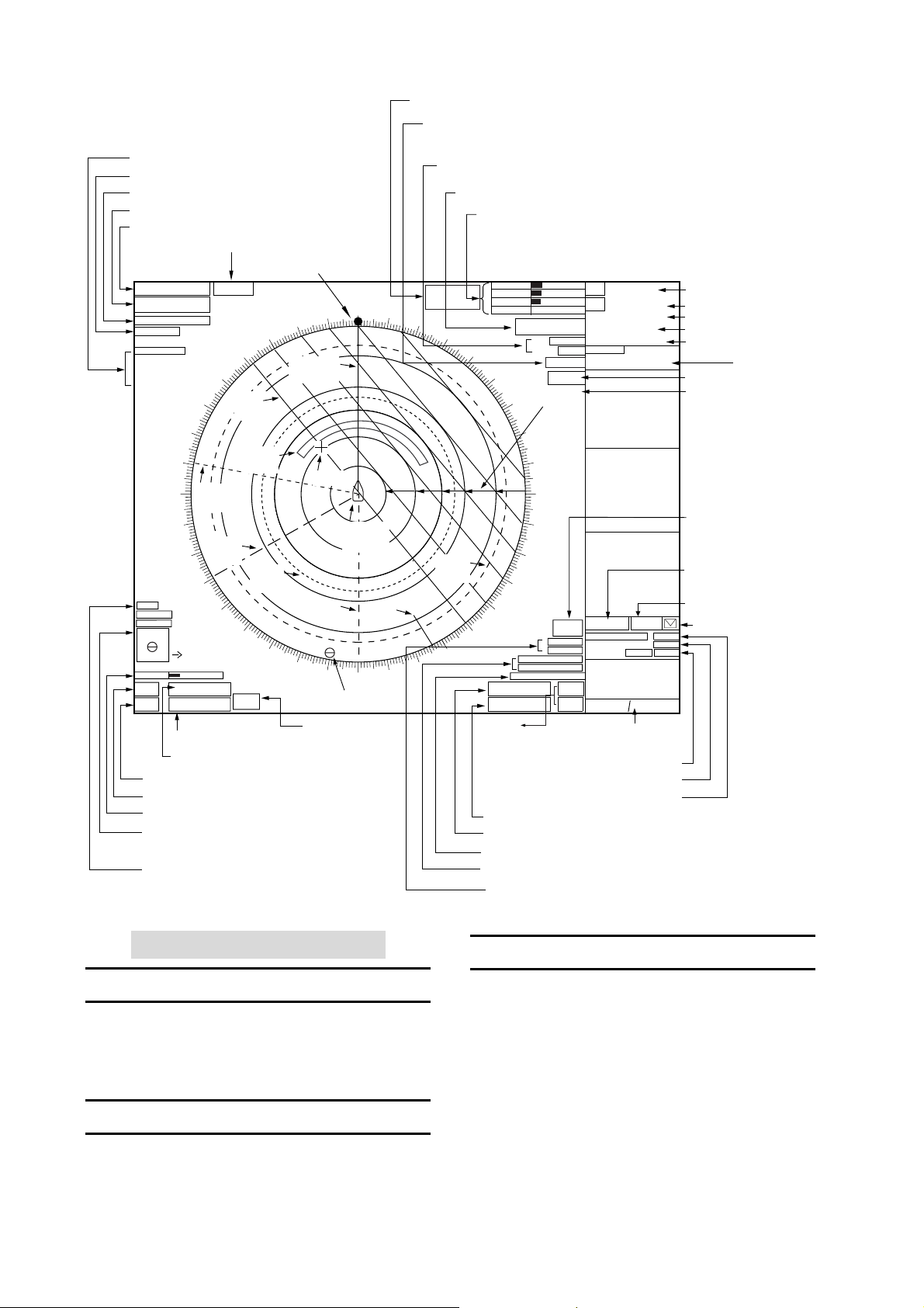
PICTURE Box, Main Picture Settings
PULSELENGTH Box
ANTENNA Box
PRESENTATION MODE Box
RANGE Box
DISPLAY MODE Box
Heading Marker
NM/1DISPLAY
6
HEAD UP TB RM
ANT 1 X-BAND
PULSE S1
PICTURE4
IR OFF
ES OFF
EAV OFF
AUTO RAIN
OFF
300
310
RADAR
320
Index
Line
330
340
Heading
Line
290
280
270
Guard
Zone
No. 1
EBL
260
No. 2
EBL
250
No. 1
220
WATCH
11 : 28
VRM
210
200
IL1
ON
032. 0°T
5. 60NM
MARK
190.0°T, 5.75NM
BRILL1
HL
EBL1
OFF
TX
EBL2
STBY
240
230
+
26
>280.9°T<
240. 8°R
EBL2 Box
EBL1 Box
TX/STBY Box
HL OFF Box
BRILL Box
MARK Box
Bearing and range to mark
IL (Index Line) Box
Index line orientation,
Index line interval
<RADAR OPERATION>
000
350
Cursor
OS
Symbol
Stern
Marker
190
North
Marker
180
Origin Mark
WATCH Box
(Alarm watch
time)
Reference Point Box
Trial Maneuver (Elapsed time shown
when trial maneuver is active.)
SET and DRIFT Boxes
REF POINT
010
170
ANT POSN
020
030
No. 2
VRM
150
160
CURSOR DATA Box
GAIN Setting
A/C SEA Setting
A/C RAIN Setting
Note: Speed, Set and
Drift values not shown.
TUNING Setting
040
GAIN
SEA AUTO
RAIN
TUNE AUTO
050
34°40. 649 N
+
135°18. 303 E
060
070
080
25
HDG
22
19
SPD
SB
COG
000. 0°TSET
SOG
OS POSN
0. 9ktDRIFT
DGPS
TRIAL OFF
MENU
ALIGN
Range
ZOOM or ARP
Rings
DATA BOX
ZOOM, ARP,
000.0°T
0.0kt BT
0.0kt
00.0°T
0.0kt
34°40.00N
135°24.00E
Heading
WT
Speed, Source
MAN
Log Speed
Course over Ground
GPS
Speed over Ground,
Source
Position
MENU Box
Chart Align ON
or AIS DATA BOX
090
DISP
OFF
30M
TARGET LIST
Box
ARP ACQ
MODE Box*
AIS DISP Box
AIS Message Arrival
120
130
140
ALARM1
ALARM2
TRUE TRAIL OFF
>3.682NM<
VRM1
VRM2
5.221NM
CU/TM
RESET,
ALARM ACK
Box
100
110
TARGET
LIST
GZ1
GZ2
CU/TM
RESET
ALARM
ACK
CPA LIMIT Box
PAST POSN Box
ARP,
AIS DATA BOX
OFF
ARPA
AIS
MANU
VECTOR TRUE
PAST POSN REL 3M
CPA LIMIT 0. 5NM 22MIN
ALERT BOX
TARGET
CURSOR
DATA & A CQ
MENU
Guidance
Box
ARP VECTOR Box
VRM2 Box
VRM1 Box
TRAIL MODE Box
ALARM Box
*: "ATA" replaces
"ARPA" when
ATA function is
used.
Guard Zone (GZ) Box
Adjusting Screen Brilliance
Turning the Power On/Off
Open the power switch cover and press the
switch to turn on the ra dar system. To turn
off the radar, press the switch again.
Transmitting, Stand- by
Press the STBY/TX key alternately to
transmit radar pulses or set the radar to
stand-by.
1. Choose the brilliance level indicator in the
brilliance level indication box at the bottom
left corner of the screen.
2. Roll the wheel downward to increase
brilliance or roll it upward to decrease
brilliance.
2
Page 3

Manual Tuning
1. Choose the RANGE box and then push
the left or right button as appropriate to
choose the 48-mile range.
2. If using automatic tuning, choose TUNE
AUTO at the top of the screen and then
push the left button to show TUNE MAN.
3. Place the arrow on the tuning bar area in
the TUNE box.
4. Roll the wheel to adjust tuning. The best
tuning point is where the bar graph swings
maximum.
Choosing a Display Mode
1. Choose the DISPLAY MODE box.
2. Push the left button to choose appropriate
mode: radar or radar + plotter.
Choosing a Presentation Mode
1. Choose the PRESENTATION MODE box.
2. Push the left button to choose desired
mode.
Choosing a Range
1. Choose the RANGE box.
2. Push the right or left button to change the
range.
Adjusting Sensitivity
1. Choose the gain level indicator.
2. Roll the wheel downward to increase the
gain or upward to decrease it.
Automatic Adjustment of Sea
Clutter
1. If using manual sea clutter, choose SEA
MAN and then push the left button to show
SEA AUT O.
2. Place the arrow in the A/C SEA level
indicator.
3. Roll the wheel downward to increase the
A/C SEA or upward to decrease it.
Adjust in g A/C RAIN
1. Place the cursor in the A/C RAIN level
indicator.
2. Roll the wheel downward to increase the
A/C RAIN or upward to decrease it.
Suppressing Interference
1. Choose the PICTURE box.
2. Push the right button to show the
PICTURE menu.
3. Choose 1 INT REJECT and then push the
wheel.
4. Choose rejection level desired and then
push the wheel.
5. Push the right button to close the menu.
Measuring the Range
1. Place the arrow in the VRM1 or VRM2
box.
2. Push the left button to turn on the VRM.
3. Push the left button again.
4. Roll the track ball (coarse adjustment) or
wheel (fine adjustment) to align the active
variable range marker with the inner edge
of the targe t o f in te re st.
To erase a VRM, choose the appropriate
VRM readout box and then push the left
button until the VRM disappears from the
screen.
Measuring the Bearing
1. Choose the EBL1 or EBL2 box.
2. Push the left button.
3. Push the left button again.
4. Roll the track ball (coarse adjustment) or
wheel (fine adjustment) to bisect the target
with the EBL.
To erase an EBL, choose the appropriate
EBL readout box and then push the left
button until the EBL disappears from the
screen.
3
Page 4

<ARP OPERA TION>
Adjusting Symbol Brilliance
Activating, Deactivating ARP
1. Choo se the ARP AC Q MODE box.
2. Push the left button to show OFF, MAN or
AUTO MAN as appropriate.
Automatic Acquisition
1. Choose the ARP ACQ MODE box and
then push the right button.
2. Choose 1 AR P SELECT and the n push
the wheel or the left button.
3. Choose automatic acquisition condition
desired and then push the wheel or the left
button.
4. Push the right button to close the menu.
Manual Acquisition
1. With the cursor inside the effective display
area, roll the wheel to show “ACQ” in the
guidanc e box .
2. Place the cursor on the target you want to
acquire.
3. Push the left button to acquire the target.
Terminating Tracking of
Targets
1. With the cursor inside the effective display
area, roll the wheel to show “TARGET
CANCEL / EXIT” in the guidance box.
2. Place the cursor on the ARP target or
reference tar g et to c a ncel tr ack ing.
3. Push the left button or the wheel.
4. To finish, push the rig ht but to n.
Displaying Target Data
1. With cursor inside the effective disp lay
area, roll the wheel to show “TARGET
DATA & ACQ / CURSOR MENU” in the
guidanc e box .
2. Roll the trackball to place the cursor on a
desired ARP target and then push the left
button.
1. C hoose the BRILL box and then push the
right butto n.
2. Choose 0 NEXT and then push the wheel
or the left button.
[BRILL1 MENU (2/2)]
1 BACK
2 BRG CURSOR
3 EBL
4 VRM
5 INDEX LINE
6 ARP SYMBOL
7 AIS SYMBOL
8 L/L GRID
9 MARK
0 CHART
3. Choose 6 AR P SYMBOL and th en push
the wheel or the left button.
4. Roll the whe el to adjust brilliance.
5. Push the right button twice to close the
menu.
Vector Motion and Length
1. Choose VECTOR T R UE or VECT O R R EL
(whichever is displayed) at the right side of
the screen.
2. Push the left button to display VECTOR
TRUE or VECTOR REL as appropriate.
3. Choose the vector tim e box .
4. Push the left button to display time
desired.
CPA and TCPA Alarm Ranges
1. Choose the CPA LIMIT box.
2. Roll the wheel to choose the CPA value
desired and then push the wheel.
3. Choose the TCPA limit box.
4. Roll the wheel to choose TCPA value
desired and then push the wheel.
PUB.NO.OSE-35190-A
(0502,DAMI) FAR-2107/2807 SERIES
This manual is printed with
soy ink.
4
 Loading...