

Page 1

www.furuno.com
FURUNO GNSS Receiver
eRideOPUS 6/ eRideOPUS
7
Model
GV-86/ GV-87
Dead Reckoning Solution
User’s Guide
(Document No. SE16-900-002-00)
Page 2

eRideOPUS 6/ eRideOPUS 7 GV-86/ GV-87
Dead Reckoning User’s Guide
SE16-900-002-00
FURUNO ELECTRIC CO., LTD. All rights reserved.
Important Notice
No part of this manual may be reproduced or transmitted in any form or by any means, electronic or
mechanical, including photocopying and recording, for any purpose without the express written permission of
the publisher, FURUNO ELECTRIC CO., LTD.
FURUNO ELECTRIC CO., LTD. reserves the right to make changes to its products and specifications without
notice.
You expressly acknowledge and agree that use of the "Application Note" is at your sole risk.
This "Application Note" is provided 'AS IS' and without warranty of any kind and FURUNO expressly disclaims
all other warranties, express or implied, including, but not limited to, the implied warranties of merchantability,
fitness for a particular purpose and no infringement.
FURUNO does not warrant that the functions contained in the "Application Note" will meet your requirements,
or that the operation of the "Application Note" will be uninterrupted or error-free, or that defects in the
"Application Note" will be corrected.
Furthermore, FURUNO does not warrant or make any representations regarding the use or the results of the
use of the "Application Note" in terms of their correctness, accuracy, reliability, or otherwise.
No oral or written information or advice given by FURUNO authorized representative shall create a warranty or
in any way increase the scope of this warranty.
Without limiting the foregoing, FURUNO disclaims any and all express or implied warranties of any kind, and
you expressly assume all liabilities and risks, for use or operation of the "Application Note", including without
limitation.
Should the "Application Note" prove defective, you assume the entire cost of all necessary servicing, repair or
correction.
Some jurisdictions do not allow the exclusion of implied warranties, so the above exclusion may not apply to
you.
All brand and product names are registered trademarks, trademarks or service marks of their respective
holders.
Page 3

eRideOPUS 6/ eRideOPUS 7 GV-86/ GV-87
Dead Reckoning User’s Guide
SE16-900-002-00
FURUNO ELECTRIC CO., LTD. All rights reserved.
Revision History
Revision
Description
Date
0
Initial release
2017.10.24
Page 4

eRideOPUS 6/ eRideOPUS 7 GV-86/ GV-87
Dead Reckoning User’s Guide
SE16-900-002-00
FURUNO ELECTRIC CO., LTD. All rights reserved.
Table of Contents
1 General Description ············································································································· 1
2 FURUNO DR GNSS Receiver ································································································ 1
3 System Configuration ·········································································································· 2
3.1 Available Signal Combination and Supported Sensor ······················································· 2
3.2 Sensor Interface Configuration ······················································································· 3
4 Reference Circuit ················································································································ 4
4.1 SMI130 ························································································································ 4
4.2 MPU-6500 ···················································································································· 5
4.3 XV-4001BC and AIS328DQ ····························································································· 6
4.4 ITG-3500 and AIS328DQ ································································································· 7
4.5 A3G4250D and AIS328DQ ······························································································ 8
4.6 XV-8000CB and AIS328DQ ····························································································· 9
4.7 XV-8100CB and AIS328DQ ···························································································· 10
5 IMU Sensor Installation ······································································································ 12
5.1 Automatic Correction by Auto Orientation Function························································· 13
5.2 Expand Auto Orientation Range by PERDAPI,AUTOORIENT Command ····························· 13
5.3 Set Installation Angle by Misalignment ··········································································· 14
5.4 Sensor Installation Examples ························································································ 15
5.4.1 Zero Angle against Axis of IMU Sensor ···································································· 15
5.4.2 Auto Orientation Default Range ·············································································· 16
5.4.3 Auto Orientation Expansion Range ········································································· 17
5.4.4 Out of Auto Orientation Range ················································································ 18
6 Calibration ······················································································································· 19
6.1 Power on to GNSS Position Fix ····················································································· 19
6.2 GNSS Position Fix to DR Valid by Calibration Driving ······················································ 20
6.3 Calibration of Vehicle Speed Pulse and Accelerometer ···················································· 20
6.4 Calibration of Gyro Sensor ··························································································· 21
6.5 Aging and Temperature Fluctuations ············································································· 21
7 Operating of DR Backup ···································································································· 22
8 Recommended NMEA Output Sentence at Customer Evaluation Stage ··································· 22
9 Important Notice ··············································································································· 23
9.1 Important Notice for IMU Sensor ···················································································· 23
9.2 Characteristics of IMU Sensor ······················································································· 23
9.3 Layout Design against Influence of IMU Sensor by External Environment Factor ················ 23
9.4 Calibrating Operation ··································································································· 23
9.5 Receiver Start Operation ······························································································ 24
10 FAQ ······························································································································ 25
Page 5

eRideOPUS 6/ eRideOPUS 7 GV-86/ GV-87
Dead Reckoning User’s Guide
SE16-900-002-00
1
FURUNO ELECTRIC CO., LTD. All rights reserved.
1 General Description
This document describes user’s guide for achieving best performance of FURUNO Dead Reckoning (DR)
GNSS receiver (GNSS+DR receiver).
- eRideOPUS 6 (P/N: ePV6010B) Dead Reckoning Chip solution
- eRideOPUS 7 (P/N: ePV7010B) Dead Reckoning Chip solution
- GV-8720
- GV-8620
Available software: As from ENP6.33D
GNSS+DR receiver has the following external interface for DR function.
<Signal input from sensor or vehicle>
This configuration is the way of direct input from vehicle.
- FURUNO supported gyro sensor and accelerometer.
- Vehicle speed pulse signal.
- Vehicle reverse signal.
2 FURUNO DR GNSS Receiver
GNSS+DR receiver can keep the following high accuracy position and velocity performance under non GNSS
signal reception or unstable area
GNSS stand alone
GNSS+DR hybrid / DR only
GNSS stand alone
GNSS+DR hybrid
Figure 2.1 Ground Tracking Test of GNSS Stand Alone and GNSS+DR
(Upper: Tunnel, Lower: Urban Canyon)
Page 6

eRideOPUS 6/ eRideOPUS 7 GV-86/ GV-87
Dead Reckoning User’s Guide
SE16-900-002-00
2
FURUNO ELECTRIC CO., LTD. All rights reserved.
3 System Configuration
3.1 Available Signal Combination and Supported Sensor
Table 3.1 shows available signal source combinations. Based on Table 3.2, which shows FURUNO supported
IMU sensor (Gyro, Accelerometer and Gyro/Accelerometer combo sensor), please design optimized system
on customer platform.
Table 3.1 Signal Source Combination
Combination
Gyro
Accelerometer
Vehicle
speed
pulse
(*1)
Reverse
signal
(*1)
Notes
A
Detection of elevation pitch
angle is available.
B -
: Necessary signal source
Table 3.2 Supported Gyro Sensor and Accelerometer
(*2)
Sensor category
Product number
Vendor
# of
axis
Automotive
Gyro/Accelerometer
combo sensor
SMI130
Bosch
6
MPU-6500
InvenSense
6
Gyro sensor
XV-4001BC
Seiko Epson
1
ITG-3500
InvenSense
3 A3G4250D
STMicroelectronics
3 XV-8000CB
(*3)
Seiko Epson
1
XV-8100CB
(*4)
Seiko Epson
1
Accelerometer
AIS328DQ
STMicroelectronics
3 LIS331DLH
STMicroelectronics
3
Notes:
(*1) Specification of vehicle speed pulse and reverse signal
Please check the regulation and electric characteristics by GNSS+DR receiver data sheet and keep it,
otherwise customer may have risk of out of performance guarantee. It is necessary to take vehicle speed pulse
together reverse signal.
(*2) Supported IMU sensor
We verified that GNSS+DR receiver with sensor in Table 3.2 could achieve target performance by proper
calibration described at Chapter 6.
(*3) In case of using XV-8000CB, it is necessary to implement the following devices.
-AD convertor (ADS1100A3: Texas Instruments)
-Thermo sensor (LM73CIMKX-0: Texas Instruments)
-Level shifter from 5V to 3V
(*4) In case of using XV-8100CB, it is necessary to implement the following devices.
-AD convertor (ADS1100A3: Texas Instruments)
-Thermo sensor (LM73CIMKX-0: Texas Instruments)
Page 7

eRideOPUS 6/ eRideOPUS 7 GV-86/ GV-87
Dead Reckoning User’s Guide
SE16-900-002-00
3
FURUNO ELECTRIC CO., LTD. All rights reserved.
3.2 Sensor Interface Configuration
Figure 3.1shows I/O relation between the GNSS+DR receiver and the supported sensor in Table 3.2.
Sensor information
I/O signal
Pin #
ePV6010B /
ePV7010B
GV-86/
GV-87
Gyro sensor,
I2C serial clock
(SCL)
TXD2_SCL
F8
#19
Accelerometer,
Gyro/Accelerometer
combo sensor
I2C serial data
(SDA)
RXD2_SDA
G8
#18
Vehicle speed pulse
ECNT
C7
#7
Reverse signal
GPIO
E6
#1
FURUNO Dead Reckoning GNSS Receiver
ECNT
GPIO
RXD2_SDA
TXD2_SCL
RXD1
TXD1 Output data (Position, Time, Sensor status, …)
Command data (NMEA setting, Mis-alignment, …)
I2C serial address and data between sensor block
I2C serial clock from sensor block
Vehicle speed pulse
Reverse signal
UART1
I2C
Figure 3.1 Sensor Interface Configuration Block Level Diagram
Page 8

eRideOPUS 6/ eRideOPUS 7 GV-86/ GV-87
Dead Reckoning User’s Guide
SE16-900-002-00
4
FURUNO ELECTRIC CO., LTD. All rights reserved.
4 Reference Circuit
This section shows reference circuits of FURUNO supported sensor. Operation guarantee of these circuits is
just based on FURUNO original development environment, which means that FURUNO is not able to
guarantee operation at customer development environment. Therefore, please verify and check expected
operation at customer end.
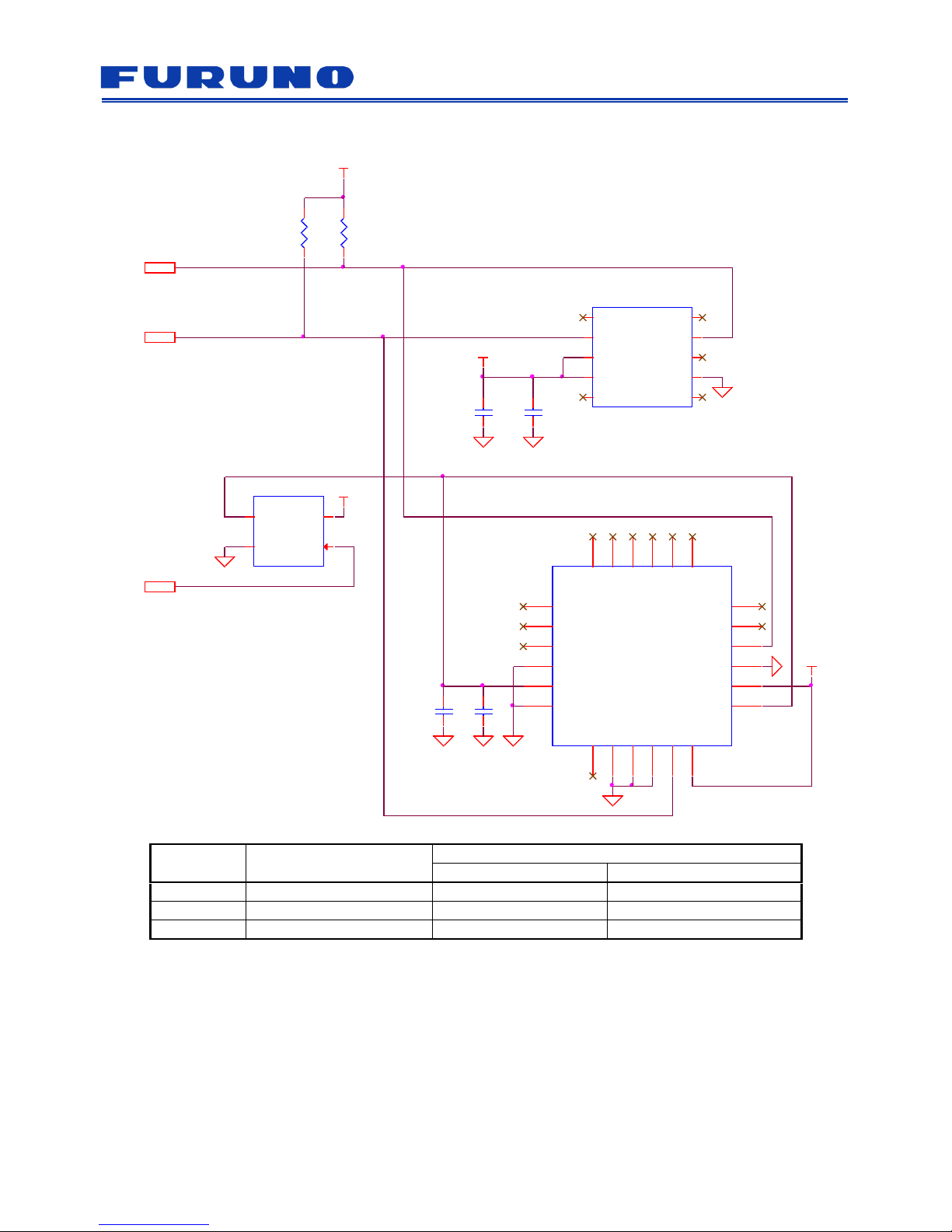
For example, in the schematics below, the both I2C lines (TXD2_SCL, RXD2_SDA) are pulled up with the
10kΩ resistors (R1, R2). Depending on the wiring capacity of the I2C line, the H and L levels may deviate from
the specified values, or the rising slope may become slow, causing timing errors. In such a case, it can be
adjusted by decreasing the value of the pull-up resistors (R1, R2) within the range that the IC can drive. Since
the wiring capacity varies according to the customer's actual layout of the circuit board, the design should be
decided by customer's evaluation.
4.1 SMI130
I/O signal
Description
Interface connection destination
eRideOPUS 6/7
GV-86/ 87
SCL
I2C clock
TXD2_SCL
TXD2_SCL
SDA
I2C address/data bus
RXD2_SDA
RXD2_SDA
Figure 4.1 Reference Circuit of SMI130
SCL
SDA
R2
10k
C1
0.1uF
R1
10k
C2
0.1uF
U1
SMI130
INT2
1
NC
2
VDD
3
GND
4
CSB2
5
GNDIO
6
PS
7
SCK
8
SDI
9
SDO2
10
VDDIO
11
INT3
12
INT4
13
CSB1
14
SDO1
15
INT1
16
VCC
VCC
VCC
(*1)
(*1)
(*2)
(*2)
(*2)
(*3)
(*3)
Page 9

eRideOPUS 6/ eRideOPUS 7 GV-86/ GV-87
Dead Reckoning User’s Guide
SE16-900-002-00
5
FURUNO ELECTRIC CO., LTD. All rights reserved.
4.2 MPU-6500
I/O signal
Description
Interface connection destination
eRideOPUS 6/7
GV-86/ 87
RESET
External reset signal
NRST
RST_N
SCL
I2C clock
TXD2_SCL
TXD2_SCL
SDA
I2C address/data bus
RXD2_SDA
RXD2_SDA
Figure 4.2 Reference Circuit of MPU-6500
U1
XC8101AA01-GR-G
VOUT
1
VSS
2
CE
3
VIN
4
R2
10k
VCC
R1
10k
VCC
SDA
SCL
RESET
U2
MPU-6500
NC
1
NC
2
NC
3
NC
4
NC
5
NC
6
AUX_CL7VDDIO8SDO/AD09REGOUT10FSYNC11INT
12
VDD
13
NC
14
NC
15
NC
16
NC
17
GND
18
RESV
19
RESV
20
AUX_DA
21
nCS
22
CSL/SCLK
23
SDA/SDI
24
C1
0.1uF
C3
0.1uF
C2
0.01uF
VCC
VCC
(*4)
(*3)
(*3)
(*1)
(*1)
(*1)
(*2)
(*2)
(*2)
(*2)
Page 10
eRideOPUS 6/ eRideOPUS 7 GV-86/ GV-87
Dead Reckoning User’s Guide
SE16-900-002-00
6
FURUNO ELECTRIC CO., LTD. All rights reserved.
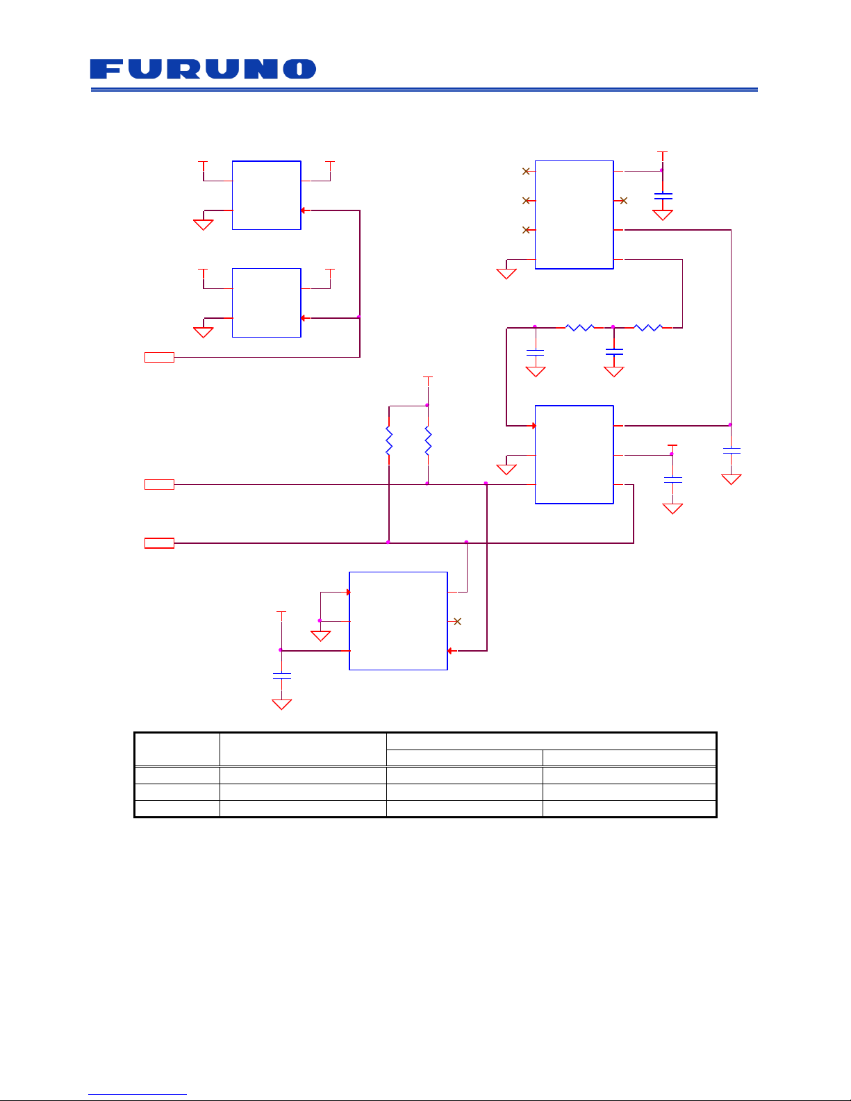
4.3 XV-4001BC and AIS328DQ
I/O signal
Description
Interface connection destination
eRideOPUS 6/7
GV-86/ 87
RESET
External reset signal
NRST
RST_N
SCL
I2C clock
TXD2_SCL
TXD2_SCL
SDA
I2C address/data bus
RXD2_SDA
RXD2_SDA
Figure 4.3 Reference Circuit of XV-4001BC and AIS328DQ
R1
10k
R2
10k
VCC
VCC
U2
XC8101AA01-GR-G
VOUT
1
VSS2CE
3
VIN
4
SDA
RESET
SCL
U3
AIS328DQ
NC
1
NC
2
INT_2
3
Reserv ed
4
VDD
5
GND
6
INT_17GND8GND9GND10SPC/SCL11CS
12
Reserv ed
13
VDD_IO
14
SDO/SA0
15
SDI/SDO/SDA
16
NC
17
NC
18
NC
19NC20NC21NC22NC23NC24
C3
10uF
C4
0.1uF
VCC
U1
XV-4001BC
Reserv ed
1
SCL
2
SS
3
VDD
4
Reserv ed5Reserv ed
6
GND
7
MOSI
8
SDA
9
Reserv ed
10
VCC
C2
10uFC10.1uF
(*1)
(*1)
(*1)
(*4)
(*3)
(*3)
(*2)
(*2)
(*2)
Page 11

eRideOPUS 6/ eRideOPUS 7 GV-86/ GV-87
Dead Reckoning User’s Guide
SE16-900-002-00
7
FURUNO ELECTRIC CO., LTD. All rights reserved.
4.4 ITG-3500 and AIS328DQ
I/O signal
Description
Interface connection destination
eRideOPUS 6/7
GV-86/ 87
RESET
External reset signal
NRST
RST_N
SCL
I2C clock
TXD2_SCL
TXD2_SCL
SDA
I2C address/data bus
RXD2_SDA
RXD2_SDA
Figure 4.4 Reference Circuit of ITG-3500 and AIS328DQ
U7
AIS328DQ
NC
1
NC
2
INT_2
3
Reserv ed
4
VDD
5
GND
6
INT_17GND8GND9GND10SPC/SCL11CS
12
Reserv ed
13
VDD_IO
14
SDO/SA0
15
SDI/SDO/SDA
16
NC
17
NC
18
NC
19NC20NC21NC22NC23NC24
VCC
C5
10uF
C4
0.1uF
U1
XC8101AA01-GR-G
VOUT
1
VSS2CE
3
VIN
4
C2
0.1uF
U2
ITG-3500
SDA/SDI
1
NC
2
VDDIO
3
/CS
4
RESV5AD0/SD06REGOUT7FSYNC
8
VDD
9
INT
10
NC
11
GND
12
NC
13
RESV-G
14NC15
SCL/SCLK
16
C3
0.1uF
C1
0.01uF
VCC
R2
10k
R1
10k
VCC
VCC
RESET
SDA
SCL
(*4)
(*3)
(*3)
(*1)
(*1)
(*1)
(*2)
(*2)
(*2)
Page 12

eRideOPUS 6/ eRideOPUS 7 GV-86/ GV-87
Dead Reckoning User’s Guide
SE16-900-002-00
8
FURUNO ELECTRIC CO., LTD. All rights reserved.
4.5 A3G4250D and AIS328DQ
I/O signal
Description
Interface connection destination
eRideOPUS 6/7
GV-86/ 87
RESET
External reset signal
NRST
RST_N
SCL
I2C clock
TXD2_SCL
TXD2_SCL
SDA
I2C address/data bus
RXD2_SDA
RXD2_SDA
Figure 4.5 Reference Circuit of A3G4250D and AIS328DQ
R1 10k
U2
A3G4250D
Vdd_IO
1
SCL/SPC
2
SDA/SDI/SDO
3
SDO/SA0
4
CS5DRDY/INT26INT7RES
8
RES
9
RES
10
RES
11
RES
12
GND
13
PLLFILT
14
RES
15
VDD
16
R3
10k
R2
10k
C5
0.1uF
VCC
VCC
VCC
VCC
C2
10uF
C4 0.47uF
C1 0.01uF
C3
0.1uF
U1
XC8101AA01-GR-G
VOUT
1
VSS2CE
3
VIN
4
SDA
RESET
SCL
U3
AIS328DQ
NC
1
NC
2
INT_2
3
Reserv ed
4
VDD
5
GND
6
INT_17GND8GND9GND10SPC/SCL11CS
12
Reserv ed
13
VDD_IO
14
SDO/SA0
15
SDI/SDO/SDA
16
NC
17
NC
18
NC19NC20NC21NC
22NC23NC24
C7
10uF
C6
0.1uF
VCC
(*4)
(*3)
(*3)
(*1)
(*1)
(*1)
(*2)
(*2)
(*2)
(*2)
Page 13

eRideOPUS 6/ eRideOPUS 7 GV-86/ GV-87
Dead Reckoning User’s Guide
SE16-900-002-00
9
FURUNO ELECTRIC CO., LTD. All rights reserved.
4.6 XV-8000CB and AIS328DQ
I/O signal
Description
Interface connection destination
eRideOPUS 6/7
GV-86/ 87
RESET
External reset signal
NRST
RST_N
SCL
I2C clock
TXD2_SCL
TXD2_SCL
SDA
I2C address/data bus
RXD2_SDA
RXD2_SDA
Figure 4.6 Reference Circuit of XV-8000CB and AIS328DQ
C4
2.2uF
VCCI_3V3
U6
LM73CIMKX-0
ADDR
1
GND
2
VDD3SMBCLK
4
ALERT_N
5
SMBDAT
6
C9
0.1uF
R6
10k
VCCI_3V3
R5
10k
U8
AIS328DQ
NC
1
NC
2
INT_2
3
Reserv ed
4
VDD
5
GND
6
INT_17GND8GND9GND10SPC/SCL11CS
12
Reserv ed
13
VDD_IO
14
SDO/SA0
15
SDI/SDO/SDA
16
NC
17
NC
18
NC19NC20NC21NC22NC23NC
24
VCC_3V3
C11
10uF
C10
0.1uF
VCCI_3V3
U2
XC8101AA01-GR-G
VOUT
1
VSS2CE
3
VIN
4
VCC_3V3
RESET
VCCI_3V3
U1
XC8101AA01-GR-G
VOUT
1
VSS2CE
3
VIN
4
VCC_5V0
VCCI_3V3
VCCI_5V0
C8
1uF
C2
0.1uF
R1 3.3k R2 3.3k
C1
2.2uF
C3
2.2uF
U3
XV-8000CB
NC
1
GND
2
VDD
3
NC
4
NC
5
VOUT
6
VTEMP
7
NC
8
VCCI_5V0
R3
3.3k +/- 1%
R4
3.3k +/- 1%
VCCI_5V0
VCCI_3V3
C6
0.1uF
VCCI_5V0
U5
TCA9517DGKR
VCCA
1
SCLA
2
SDAA
3
GND
4
EN
5
SDAB
6
SCLB
7
VCCB
8
C7
0.1uF
SCL
SDA
U4
ADS1100A3IDBVT
Vin+
1
GND
2
SCL3SDA
4
VDD
5
Vin-
6
VCCI_5V0
R8
10k
R7
10k
VCCI_5V0
C5
0.1uF
(*4)
(*4)
(*3)
(*3)
(*1)
(*1)
(*1)
(*5)
(*5)
(*5)
(*5)
(*6)
(*6)
Page 14
eRideOPUS 6/ eRideOPUS 7 GV-86/ GV-87
Dead Reckoning User’s Guide
SE16-900-002-00
10
FURUNO ELECTRIC CO., LTD. All rights reserved.
4.7 XV-8100CB and AIS328DQ
I/O signal
Description
Interface connection destination
eRideOPUS 6/7
GV-86/ 87
RESET
External reset signal
NRST
RST_N
SCL
I2C clock
TXD2_SCL
TXD2_SCL
SDA
I2C address/data bus
RXD2_SDA
RXD2_SDA
Figure 4.7 Reference Circuit of XV-8100CB and AIS328DQ
C4
0.1uF
VCCI_3V3
U5
LM73CIMKX-0
ADDR
1
GND
2
VDD
3
SMBCLK
4
ALERT_N
5
SMBDAT
6
C6
0.1uF
VCCI_3V3
R4
10k
R3
10k
U3
XC8101AA01-GR-G
VOUT
1
VSS
2
CE
3
VIN
4
VCC_3V3
RESET
U2
XC8101AA01-GR-G
VOUT
1
VSS
2
CE
3
VIN
4
VCCI_3V3
VCC_3V0VCCI_3V0
C1
0.1uF
R13.3k
C3
2.2uF
C2
2.2uF
VCCI_3V0
SDA
SCL
U4
ADS1100A3IDBVT
Vin+
1
GND
2
SCL
3
SDA
4
VDD
5
Vin-
6
VCCI_3V0
C5
0.1uF
U1
XV-8100CB
NC
1
NC
2
NC
3
GND4VOUT
5
VREF
6
NC
7
VDD
8
R23.3k
(*7)
(*7)
(*7)
(*4)
(*4)
(*3)
(*3)
(*1)
(*1)
(*1)
Page 15

eRideOPUS 6/ eRideOPUS 7 GV-86/ GV-87
Dead Reckoning User’s Guide
SE16-900-002-00
11
FURUNO ELECTRIC CO., LTD. All rights reserved.
Notes:
(*1) When the I2C master device is eRideOPUS 6/eRideOPUS 7 and using 1.8V I/O power supply, please
change to 3.3V I/O signal voltage with level shifter.
(*2) The power supply (VCC) should be common with the receiver.
(*3) Since this resistance value may not satisfy the electrical characteristics due to the floating capacitance of
the line, please decide the resistance value in consideration of the floating capacitance of the line.
(*4) In case only receiver which is eRideOPUS 6/ eRideOPUS 7 or GV-86/GV-87 (I2C master device) has
reset from normal operation, there is a risk of misreading data from sensor after releasing reset. In order to
avoid this issue, it is necessary to be activating reset of sensor when I2C master device has reset.
Therefore, it is necessary to control power supply of sensor by using power switch with the reset control
port due to no reset port at the sensor.
(*5) In case of using XV-8000CB, it is necessary to implement the following devices.
- AD convertor (ADS1100A3: Texas Instruments).
- Thermo sensor (LM73CIMKX-0: Texas Instruments).
- Level shifter from 5V to 3.3V.
(*6) 1% resistor is necessary.
(*7) In case of using XV-8100CB, it is necessary to implement the following devices.
- AD convertor (ADS1100A3: Texas Instruments).
- Thermo sensor (LM73CIMKX-0: Texas Instruments).
Page 16

eRideOPUS 6/ eRideOPUS 7 GV-86/ GV-87
Dead Reckoning User’s Guide
SE16-900-002-00
12
FURUNO ELECTRIC CO., LTD. All rights reserved.
5 IMU Sensor Installation
For the installation of the IMU sensor, the GNSS+DR receiver has specification values for the inclination and
the deviation of the coordinate system of the vehicle and the IMU sensor. The GNSS+DR receiver has a
function to correct the inclination and the deviation within the specification value.
(1) Method of automatically correcting the inclination and the deviation of installation angle by the Auto
Orientation function
(2) Method of presetting the inclination of the known installation angle by the misalignment command
With these functions, it is possible to correct and eliminate the output error of the IMU sensor caused by the
inclination and deviation.
The Auto Orientation function can also expand the range of angles that can be automatically corrected by
AUTOORIENT command.
<Definition of coordinate system and axis>
Here are definitions of axis against sensor unit installation angle:
- Direction of forward movement: X-axis
- Horizontal to the direction of movement: Y-axis
- Vertical to the direction of movement: Z-axis
Rotation angles to the each axis are defined as follows:
- Rotation angle around the X axis: ΔθX Roll angle
- Rotation angle around the Y axis: ΔθY Pitch angle
-
Rotation angle around the Z axis: ΔθZ Yaw angle
Figure 5.1 (a) to (d) shows inclination against each axis.
Z
X
Y
(a) No inclination
Z
X
Y
(b) Inclines ΔθZ to the direction of movement
Z
X
Y
(c) Inclines ΔθX to the horizontal direction
Z
X
Y
(d) Inclines ΔθY to the height direction
Δθ
Y
0
0
0
Surface
0
Direction of
movement
Δθ
Z
Δθ
X
Figure 5.1 Sensor Unit Installation Angle Definition
Page 17

eRideOPUS 6/ eRideOPUS 7 GV-86/ GV-87
Dead Reckoning User’s Guide
SE16-900-002-00
13
FURUNO ELECTRIC CO., LTD. All rights reserved.
When the axis described in the IMU sensor data sheet defines the Z-axis and the Y-axis opposite to the DR
receiver axis definition, the DR receiver changes the Z-axis and Y-axis direction to correspond to the definition
described in this document.
5.1 Automatic Correction by Auto Orientation Function
Auto Orientation is a function to automatically correct the output error due to the inclination and deviation of the
IMU sensor. Table 5.1 shows the IMU sensor combination and the allowable angle range in which the Auto
Orientation operates.
Table 5.1 Functional Range of Auto Orientation (Default)
#
Sensor combination
ΔθZ
Yaw angle
ΔθX
Roll angle
ΔθY
Pitch
angle
Notes
1
3-axis gyro sensor,
3-axis accelerometer,
vehicle speed pulse
±15
±60
±60
2 ±45
±45
In case of using A3G4250D
3
1-axis gyro sensor,
3-axis accelerometer,
vehicle speed pulse
±15
±30
4
3-axis or 1-axis gyro sensor,
vehicle speed pulse
±15
±15
5.2 Expand Auto Orientation Range by PERDAPI,AUTOORIENT Command
In case of using 3-axis gyro sensor, 3-axis accelerometer and vehicle speed pulse, it is possible to expand the
Auto Orientation range for the Roll angle or the Pitch angle by $PERDAPI,AUTOORIENT,1*6E. Table 5.2
shows the expanded range.
Table 5.2 Functional Range of Auto Orientation (Expansion)
#
Sensor
combination
ΔθZ
Yaw angle
ΔθX
Roll angle
ΔθY
Pitch angle
Notes
5
3-axis gyro sensor,
3-axis accelerometer,
vehicle speed pulse
±15
±15
±75
Pitch angle expansion
Using SMI130, MPU6500/ ITG3500
6
±180
±45
Roll angle expansion
Using SMI130, MPU6500/ ITG3500
7
±45
-165 to -180
+165 to +180
±45
Roll angle expansion
Using A3G4250D
Page 18

eRideOPUS 6/ eRideOPUS 7 GV-86/ GV-87
Dead Reckoning User’s Guide
SE16-900-002-00
14
FURUNO ELECTRIC CO., LTD. All rights reserved.
5.3 Set Installation Angle by Misalignment
When the IMU sensor is not installed within the Auto Orientation range, which means that the installation angle
is exceeded the range described in Table 5.1 and Table 5.2, it is possible to set the installation angle by the
misalignment command
(*1)
(Gyro sensor: PERDAPI,GYROALIGN, Accelerometer: PERDAPI,ACCELALIGN).
Misalignment operating necessity condition and flow is as follow:
Operating necessity condition:
- Initial installation
- Change installation angle.
Operating process flow:
1. Install the unit with IMU sensor.
2. Check the installation angle of IMU sensor.(delta angle)
3. Operate the GNSS+DR receiver with vehicle stop condition.
4. Send $PERDAPI,STOP,DRPARK*5D command and stop normal operating of GNSS+DR receiver.
5. Send delta angle by misalignment set command.
(Gyro sensor misalignment command)
$PERDAPI,GYROALIGN,Δθx,Δθy,Δθz*hh
(Accelerometer sensor misalignment command)
$PERDAPI,ACCELALIGN,Δθx,Δθy,Δθz*hh
*Setting sequence of misalignment angle against absolute axis is ΔθX -> ΔθY -> ΔθZ.
6. Send $PERDAPI,START,SIMCOLD*48 command and initiate normal operating GNSS+DR receiver.
(*2)
Notes:
(*1) As the misalignment data returns to the default in the following condition, it is recommended to register the
commands in ESIPLIST.
- Send PERDAPI,STOP,DRPARK command
- Power off
- Hardware reset
(*2) Do not change the installation angle of IMU sensor during normal operating.
Page 19

eRideOPUS 6/ eRideOPUS 7 GV-86/ GV-87
Dead Reckoning User’s Guide
SE16-900-002-00
15
FURUNO ELECTRIC CO., LTD. All rights reserved.
5.4 Sensor Installation Examples
Here are sensor, which is 3-axis gyro and 3-axis accelerometer, installation examples with the GNSS+DR
receiver evaluation kit (VN-871 or VN-861).
5.4.1 Zero Angle against Axis of IMU Sensor
X
Y
Z
Traveling
direction
O
This installation is ideal, which means that this
installation angle meets requirement specifications
of IMU sensor based on data sheet.
(a) (ΔθX, ΔθY, ΔθZ) = (0, 0, 0)
Figure 5.2 Zero Angle against Axis of IMU Sensor
Page 20

eRideOPUS 6/ eRideOPUS 7 GV-86/ GV-87
Dead Reckoning User’s Guide
SE16-900-002-00
16
FURUNO ELECTRIC CO., LTD. All rights reserved.
5.4.2 Auto Orientation Default Range
In case of Figure 5.3 (b), (c) and (d), it is possible to automatically correct the inclination of IMU sensor by
using 3-axis gyro sensor and 3-axis accelerometer.
X
Z
Y
Traveling
direction
+15°
O
This installation is that the rotate angle against
Z-axis is +15 degrees, which means that heading of
IMU sensor is -15 degrees at clockwise against
traveling direction.
(b) (ΔθX, ΔθY, ΔθZ) = (0, 0, +15)
Z
X
Traveling
direction
Y
-15°
O
This installation is that the rotate angle against
X-axis is -15 degrees, which means that horizontal
plane of IMU sensor is -15 degrees at counter
clockwise against Y-axis.
(c) (ΔθX, ΔθY, ΔθZ) = (-15, 0, 0)
Z
Y
X
Traveling
direction
O
+30°
This installation is that the rotate angle against
Y-axis is +30 degrees, which means that elevation
angle of IMU sensor is +30 degrees against traveling
direction.
(d) (ΔθX, ΔθY, ΔθZ) = (0, +30, 0)
Figure 5.3 Installation Examples within Auto Orientation Default Range
Page 21

eRideOPUS 6/ eRideOPUS 7 GV-86/ GV-87
Dead Reckoning User’s Guide
SE16-900-002-00
17
FURUNO ELECTRIC CO., LTD. All rights reserved.
5.4.3 Auto Orientation Expansion Range
In case of Figure 5.4 (e), (f) and (g), it is possible to automatically correct the inclination of IMU sensor by using
3-axis gyro sensor and 3-axis accelerometer and “$PERDAPI,AUTOORIENT,1*6E” command.
+75°
X
Y
Z
Traveling
direction
O
This installation is that the rotate angle against
Y-axis is +75 degrees, which means that elevation
angle of IMU sensor is +75 degrees against traveling
direction.
(e) (ΔθX, ΔθY, ΔθZ) = (0, +75, 0)
X
Y
Z
Traveling
direction
O
+180°
This installation is that the rotate angle against
X-axis is +180 degrees, which means that the top
side of IMU sensor faces downward.
(f) (ΔθX, ΔθY, ΔθZ) = (+180, 0, 0)
O
X
Y
Z
Traveling
direction
+180°
+45°
This installation is that the rotate angle against
X-axis is +180 degrees and against Y-axis is +45
degrees, which means that the top side of IMU
sensor faces downward and the elevation angle
inclines +45 degrees.
(g) (ΔθX, ΔθY, ΔθZ) = (+180, +45, 0)
Figure 5.4 Installation Examples within Auto Orientation Expansion Range
Page 22

eRideOPUS 6/ eRideOPUS 7 GV-86/ GV-87
Dead Reckoning User’s Guide
SE16-900-002-00
18
FURUNO ELECTRIC CO., LTD. All rights reserved.
5.4.4 Out of Auto Orientation Range
In case of Figure 5.5 (h), (i) and (j), it is necessary to set misalignment data due to out of Auto Orientation
range.
Z
Y
X
Traveling
direction
O
+30°
This installation is that the rotate angle against
Z-axis is +30 degrees, which means that the heading
of IMU sensor is +30 degrees at clockwise against
the traveling direction. When the heading error is
more than +15 degrees, it is necessary to set
misalignment data. In this case (the rotate angle
against Z-axis is +30 degrees), since ΔθZ is out of
Auto Orientation range, it is necessary to send the
following commands as misalignment data.
$PERDAPI,GYROALIGN,0,0,30*16
$PERDAPI,ACCELALIGN,0,0,30*5D
(h) (ΔθX, ΔθY, ΔθZ) = (0, 0, +30)
+90°
+90°
O
X
Y
Z
Traveling
direction
This installation is that the rotate angle against
X-axis is +90 degrees and the rotate angle against
Z-axis is +90 degrees, which means that heading of
IMU sensor is +90 degrees at clockwise and the
elevation angle of IMU sensor is +90 degrees
against the traveling direction. In this case, since
Δθ
X
and ΔθZ is out of Auto Orientation range, it is
necessary to send the following commands as
misalignment data.
$PERDAPI,GYROALIGN,90,0,90*25
$PERDAPI,ACCELALIGN,90,0,90*6E
(i) (ΔθX, ΔθY, ΔθZ) = (+90, 0, +90)
O
X
Y
Z
Traveling
direction
+180°
+180°
This installation is that the rotate angle against
X-axis is +180 degrees and the rotate angle against
Z-axis is +180 degrees, which means that the
heading of IMU sensor is +180 degrees at clockwise
and the top side of IMU sensor faces downward. In
this case, since ΔθX and ΔθZ is out of Auto
Orientation range, it is necessary to send the
following commands as misalignment data.
$PERDAPI,GYROALIGN,180,0,180*25
$PERDAPI,ACCELALIGN,180,0,180*6E
(j) (ΔθX, ΔθY, ΔθZ) = (+180, 0, +180)
Figure 5.5 Installation Examples with Misalignment Command
Page 23

eRideOPUS 6/ eRideOPUS 7 GV-86/ GV-87
Dead Reckoning User’s Guide
SE16-900-002-00
19
FURUNO ELECTRIC CO., LTD. All rights reserved.
6 Calibration
Calibration is a function to estimate the output errors of IMU sensor and vehicle speed pulse. Estimated output
errors are bias and gain. The bias is an output value when the input value is 0, and the gain is a ratio of the
input value to the output value. Using the estimated bias and gain, the GNSS+DR receiver corrects the output
value of IMU sensor and vehicle speed pulse, and outputs high precision position.
The calibration method is described in the following sections.
6.1 Power on to GNSS Position Fix
[Operation]
It is necessary to do position fix in open sky as a good GNSS signal reception environment
(*1)
before starting
calibration driving.
[Check]
1. Check the position fix status with GNS and RMC sentence
Make sure that the position fix status is A or D.
Example:
Yellow high-light shows the position fix status (GNS sentence shows the position fix status of GPS,
GLONASS and Galileo from left hand).
$GNRMC,071201.776,A,3442.7276,N,13520.1229,E,0.00,30.96,130614,,,A,V*3C
$GNGNS,071201.776,3442.7276,N,13520.1229,E,AAN,18,0.5,3.6,36.7,,,V*5C
2. Check the C/N0 value with GSV sentence
The more number of satellites with C/N0 with over 40 dB-Hz, the better reception environment.
Example:
Yellow high-light shows the C/N0 value.
$GPGSV,4,1,14,19,73,309,50,03,70,345,52,27,55,031,52,16,46,084,50,1*6A
$GPGSV,4,2,14,07,40,307,52,11,39,211,49,08,19,320,46,01,15,199,40,1*61
$GPGSV,4,3,14,13,15,247,43,30,13,319,,22,11,090,46,23,05,219,42,1*6F
$GPGSV,4,4,14,42,00,000,46,93,32,161,43,,,,,,,,,1*6F
$GLGSV,2,1,07,82,71,317,56,80,67,326,53,79,50,152,52,81,30,031,55,1*7C
$GLGSV,2,2,07,83,25,238,53,73,14,329,29,78,01,151,34,,,,,1*42
Notes:
(*1) As an index of a good GNSS signal reception environment, it is more than 50% of the number of satellites
in use with signal level of over 40 dB-Hz.
Page 24

eRideOPUS 6/ eRideOPUS 7 GV-86/ GV-87
Dead Reckoning User’s Guide
SE16-900-002-00
20
FURUNO ELECTRIC CO., LTD. All rights reserved.
6.2 GNSS Position Fix to DR Valid by Calibration Driving
[Operation]
Calibration function is available by driving with more than 20 km/h at open sky. Keep the vehicle speed of more
than 20km/h at open sky. Otherwise calibration function may not work.
20Km/h overRun
Position status changes from GPS only to DR/GNSS mixed, which means that DR is valid, for a several
minutes with this condition. While DR is valid, it is not equal to complete the calibration operation.
[Check]
a) Check the IMU result verified mode with PERDCRD,R sentence
When Field 3 is 1, DR is valid.
b) Check the DR use mode with PERDCRD,R sentence
When Field 4 is 2, DR/GNSS mixed (hybrid position fix status) is valid.
Example:
$PERDCRD,R,1,2,-0.68,-8.85,-0.01,-0.4,0.1,265.6,1,10*23
6.3 Calibration of Vehicle Speed Pulse and Accelerometer
[Operation]
Same as Section 6.2.
[Check]
Check the calibration status of vehicle speed pulse and accelerometer with the following sentences.
-Vehicle speed pulse:
When Field 3 is 7 or 15
(*1)
at PERDCRI,O sentence, the calibration of vehicle speed pulse is completed.
Example:
$PERDCRI,O,7,29,2,4.00,1.569858*10
$PERDCRI,O,15,0,0,4.02,1.569858*18
Notes:
(*1) In case of detecting reverse signal at status 7, the status becomes 15. It is necessary to check valid of
reverse signal before starting calibration of vehicle speed pulse.
-Accelerometer:
When Field 17 is 3 at PERDCRI,A sentence, the calibration of accelerometer is completed.
Example:
$PERDCRI,A,3,7,724,-701,-25,2572,2572,2572,689,-717,-22,88,44,0,3*19
Page 25

eRideOPUS 6/ eRideOPUS 7 GV-86/ GV-87
Dead Reckoning User’s Guide
SE16-900-002-00
21
FURUNO ELECTRIC CO., LTD. All rights reserved.
6.4 Calibration of Gyro Sensor
[Operation]
Calibration function of gyro sensor is available by driving with a several times (8 to 12 times) of right or left turn
at GNSS or GNSS+DR status of open sky level. It is available to do mix calibration with Section 6.2 and 6.3.
Turn Left Turn Right
[Check]
When Field 17 is 5,7,13 or 15 at PERDCRI,G sentence, the calibration of gyro sensor is completed.
Example:
$PERDCRI,G,3,7,79,-8,-27,2601,2601,2601,79,-8,-27,88,44,0,7*1A
6.5 Aging and Temperature Fluctuations
Even after completion of calibration, the GNSS+DR receiver will continue to estimate bias and gain during
actual operation. This is to follow changes in characteristics due to aging and temperature fluctuations.
Page 26

eRideOPUS 6/ eRideOPUS 7 GV-86/ GV-87
Dead Reckoning User’s Guide
SE16-900-002-00
22
FURUNO ELECTRIC CO., LTD. All rights reserved.
7 Operating of DR Backup
The GNSS+DR receiver has two kinds of backup source, which are the backup RAM and the Flash ROM. The
backup data is stored into the backup RAM while a backup power is supplied to the GNSS+DR receiver. The
GNSS+DR receiver can also store the backup data into the Flash ROM by sending PERDAPI,STOP,DRPARK
command.
When the backup data is valid at the next operating, the GNSS+DR receiver outputs the position in DR only
mode based on the backup data until GNSS position fix. When the GNSS+DR receiver receives GNSS signals
and confirms the GNSS positioning result is correct, the position fix status changes to DR/GNSS mixed mode.
When changing the vehicle, installation angle and installation position of IMU sensor, the backup data should
be deleted by sending PERDAPI,START,SIMCOLD command. And then, calibrate the IMU sensor parameters
again.
8 Recommended NMEA Output Sentence at Customer Evaluation Stage
When evaluating the DR performance, it is recommended to collect PERDCRD, PERDCRI sentences and
Diag data. It is very useful for analyzing the log data at FURUNO.
The recommended operating is as follow:
1. Send STOP command ($PERDAPI,STOP,DRPARK*5D).
2. Send output command ($PERDAPI,CROUT,DI*09) for output valid of PERDCRD and PERDCRI
sentence.
3. Send Diag data output command ($PERDSYS,RECPLAY,ON*0B).
4. Send START command ($PERDAPI,START*37).
Notes:
When outputting the Diag data, it is necessary to change the baud rate to 460800 bps by the following
command.
$PERDCFG,UART1,460800*68
In case of using 460800 bps, taka care about UART communication error rate and do not use this baud rate
except Diag data collection.
Page 27

eRideOPUS 6/ eRideOPUS 7 GV-86/ GV-87
Dead Reckoning User’s Guide
SE16-900-002-00
23
FURUNO ELECTRIC CO., LTD. All rights reserved.
9 Important Notice
9.1 Important Notice for IMU Sensor
Please design and implement based on the data sheet of IMU sensor. In addition, please verify the products to
achieve the target performance.
9.2 Characteristics of IMU Sensor
The GNSS+DR receiver is designed to provide accurate performance by estimating errors of bias and gain
described in the data sheet of IMU sensor. The performance may be degraded by influence of some
characteristics not described in the data sheet of IMU sensor.
9.3 Layout Design against Influence of IMU Sensor by External Environment Factor
Since the IMU sensor is a very sensitivity device against the following three external environment factors, keep
the layout design of IMU sensor based on the below guideline.
(1) Temperature factor
External temperature has a negative impact on the angular velocity and the acceleration of IMU sensor. In
order to avoid this influence, consider the following guideline of design.
a) Implement the IMU sensor apart from heat sources.
b) Protect influences of dynamic temperature change by surrounding air.
(2) Mechanical factor
The vibration and impulse against IMU sensor has a negative impact on the angular velocity and the
acceleration of IMU sensor. Below are examples to avoid this influence.
a) Implement the IMU sensor nearby the holding part of the board.
b) Clip the board by shock-absorbing material with labor.
c) Fix the unit or board, which IMU sensor is implemented, by screws.
(3) Other factor
Because of the gyro sensor and the accelerometer are MEMS devices, these devices have a resonant
frequency for operating MEMS mechanically and electric frequency characteristics internally. In case the
MEMS device has an external mechanical or electrical impact which is close to the frequency characteristics of
MEMS device, there is a risk of significant degradation regarding the output characteristics of sensor.
Therefore, user should design the circuit of surrounding area of sensor for preventing influences of external
mechanical vibration or electrical signal characteristics such as system clock signal.
9.4 Calibrating Operation
Good GNSS signal reception environment provides suitable calibration of IMU sensor. Therefore, install the
antenna on the place which good GNSS signals can be received. Also, take care that there is enough antenna
gain and no degrade of reception signal by noise on actual operation.
For calibrating the vehicle speed pulse, it needs to drive faster than 20km/h under good GNSS signal reception
environment. When an actual operation is traveling at a low-speed (ex. the bus drives in an urban area.), it
needs much time for calibration or the calibration may not be finished. Therefore, it is recommended to start
the actual operation after the calibration.
Page 28

eRideOPUS 6/ eRideOPUS 7 GV-86/ GV-87
Dead Reckoning User’s Guide
SE16-900-002-00
24
FURUNO ELECTRIC CO., LTD. All rights reserved.
9.5 Receiver Start Operation
The GNSS+DR receiver backs up the last updated position, the direction and the DR parameters. At the next
power on, the GNSS+DR receiver starts the positioning in DR only mode by using the backup data. After that,
when the direction calculated by DR is coincident with the GNSS direction, the position mode changes to
DR/GNSS mixed mode. The GNSS+DR receiver outputs the positioning result by DR only until the position
mode changes to the DR/GNSS mixed mode.
Page 29

eRideOPUS 6/ eRideOPUS 7 GV-86/ GV-87
Dead Reckoning User’s Guide
SE16-900-002-00
25
FURUNO ELECTRIC CO., LTD. All rights reserved.
10 FAQ
Q1. How do we check calibration completion status?
A1. As a first step, please check “PERDCRD,R” sentence as DR valid. When Field 3 of this sentence is
indicated as “1”, DR mode is valid. The example of the sentence is as below.
Example:$PERDCRD,R,1,2,-2.28,-12.12,0.16,-1.3,-0.5,260.5,3,17*17
Check this value is indicated as “1”
As the next step, please check the following sentence status as calibration completion with calibration
driving.
Calibration completion status of vehicle speed pulse:
Field 3 (odomtrConf) of PERDCRI,O is 7 or 15
Calibration completion status of accelerometer :
Field 17 (learnmode) of PERDCRI,A is 3
Calibration completion status of accelerometer :
Field 17 (learnmode) of PERDCRI,G is 5, 7, 13 or 15
Q2. The sensors do not become valid.
A2. Please check if the gyro sensor and the accelerometer are installed in accordance with the direction
explained in the chapter 5. In case vehicle speed pulse is used, please confirm the vehicle speed pulse
satisfies the electrical specifications and the count of vehicle speed pulse.
Q3. Is it possible to make DR positioning with gyro sensor only?
A3. No, it is not. It is required to use vehicle speed pulse together with gyro sensor.
Q4. Is the reverse signal required when using vehicle speed pulse?
A4. Yes.
Q5. How do we check the elevation pitch angle based on the sensor information?
A5. Refer Field 9 (pitch) of PERDCRD,R sentence.
Q6. Does altitude data reflect on elevation pitch angle based on sensor information?
A6. No. altitude data with GNS sentence does not reflect on elevation pitch angle.
Q7. In case we lost vehicle speed pulse with combination of gyro sensor, accelerometer and vehicle speed
pulse, what kind of behavior we observe.
A7. In case of non-vehicle speed pulse at first time, position fix status change to DR status by using
information of accelerometer as velocity source. In case of non-vehicle speed pulse on the way, user
observes irregular ground tracking performance for a while until calibration reset. When user observes
Field 11 (counts Status) of PERDCRD,R is 0, accelerometer is available as velocity source.
Q8. Do you have reference circuit regarding IMU sensor interface?
A8. Please refer chapter 4.
Page 30

eRideOPUS 6/ eRideOPUS 7 GV-86/ GV-87
Dead Reckoning User’s Guide
SE16-900-002-00
26
FURUNO ELECTRIC CO., LTD. All rights reserved.
Q9. Is it possible to use other than vehicles?
A9. No. The DR receiver is designed for car navigation systems and telematics terminals.
Q10. Not completed calibration of Gyro.
A10. Please check whether there are more than the 50% of the number of satellites in use with signal level of
over 40dBHz signal level.
 Loading...