


OPERATOR'S MANUAL
DOPPLER SONAR
MODEL
DS-30
www.furuno.co.jp

Thepaperusedinthismanual
9‑52Ashihara‑cho,
Fax:
A:AUG
1992
.
U:SEP.16,2009
Pub.No.
(
)
*
00080474414
**00080474414
*
Nishinomiya,662‑8580,JAPAN
Telephone: +81‑(0)798‑65‑2111
+81‑(0)798‑65‑4200
iselementalchlorinefree.
・FURUNOAuthorizedDistributor/Dealer
Allrightsreserved.
TATA
DS‑30
PrintedinJapan
OME‑72360‑U
*00080474414**00080474414*
*00080474414*

SAFETY INSTRUCTIONS
i
WARNING
ELECTRICAL SHOCK HAZARD
Do not open the equipment.
Only qualified personnel
should work inside the
equipment.
Immediately turn off the power at the
switchboard if water leaks into the
equipment or an object is dropped into
the equipment.
Continued use of the equipment can cause
fire or electrical shock. Contact a FURUNO
agent for service.
Do not place liquid-filled containers on
the top of the equipment.
Fire or electrical shock can result if the
liquid spills into the equipment.
Do not disassemble or modify the
equipment.
CAUTION
Do not use the equipment for other than
its intended purpose.
Improper use of the equipment can result
in personal injury or equipment damage.
Turn off the equipment immediately if
you feel it is abnormal.
Turn off the power from the switchboard if
the equipment is emitting strange noises
or becomes excessively hot. Contact your
dealer for advice.
The useable ambient temperature range
to
is 15°C
Do not use the equipment out of the
above temperature range.
Do not place objects around the
equipment.
Overheating may result.
55°C.
Fire, electrical shock or serious injury can
result.
Keep the equipment away from rain
and water splash.
Fire or electrical shock can result if the
rain or water gets into the equipment.
Do not operate the equipment with wet
hands.
Electrical shock can result.
Keep heater away from equipment.
A heater can melt the equipment's power
cord, which can cause fire or electrical
shock.
Use the proper fuse.
Fuse rating is shown on the equipment.
Use of a wrong fuse can result in damage
to the equipment.
Do not power the equipment when the
transducer is in air.
The transducer may become damaged.
Handle all units carefully.
Damage can lead to corrosion.
Do not use chemical cleaners such as
alcohol, acetone and benzine to clean
the equipment.
Chemical cleaners can remove paint and
markings. Use only a soft, dry cloth. For
stubborn dirt, use a soft cloth moistened
with water-diluted mild detergent.
When dry docked remove marine life
from the transducer.
Remove marine life to maintain good
sensitivity.
Do not paint the transducer face.
Further, handle the transducer with
care.
Paint will affect equipment performance.
CAUTION
If the optional rate gyro is installed,
turn on the power when the ship is dead
in water or running straight.
The heading generated by the rate gyro
is used as reference, therefore turning on
the equipment while the ship is turning will
result in large heading errror.
WARNING
To avoid electrical shock, do not
remove cover. No user-serviceable
parts inside.
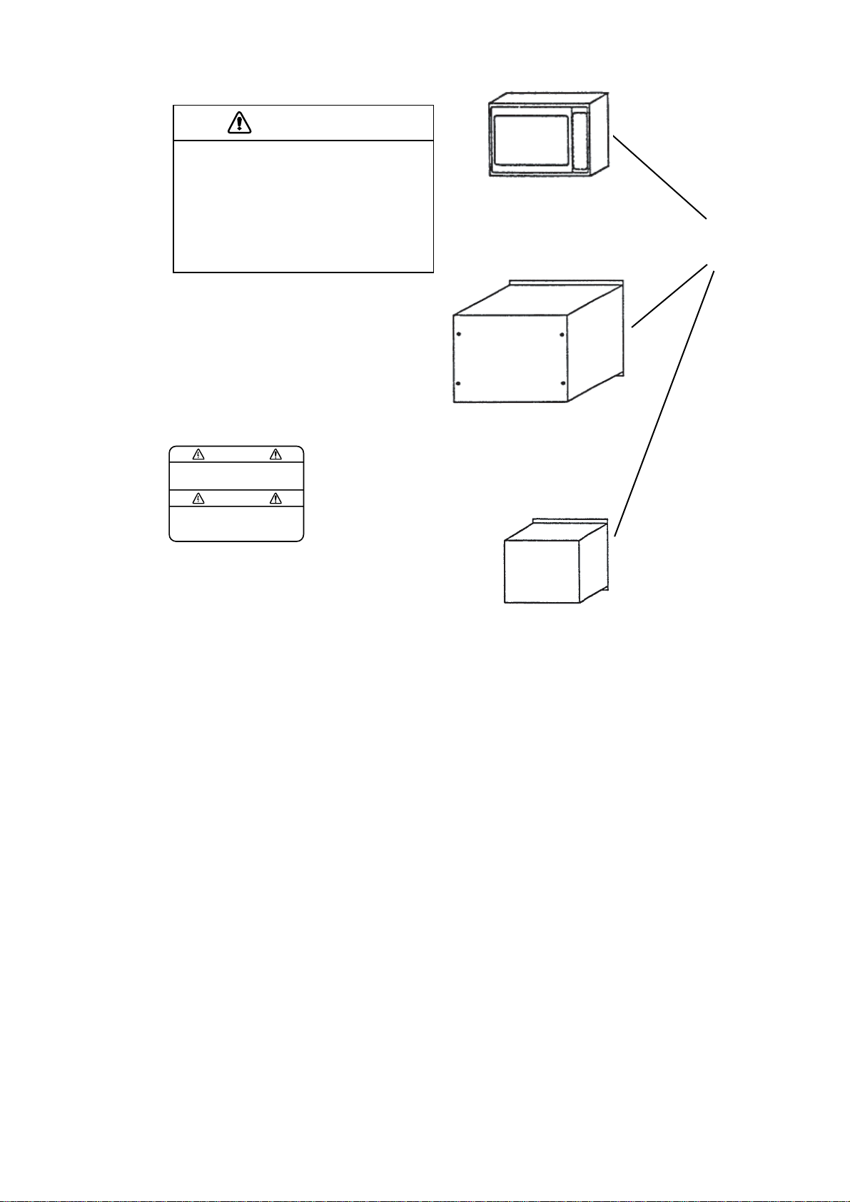
Name: Warning Label (1)
Type: 86-003-1011
Code No.: 100-236-230
MAIN DISPLAY UNIT
DS-300/301
Warning
label
PROCESSOR UNIT
DS-310
TRANSCEIVER UNIT
DS-320
ii


v
5. Tr ansverse Speed at Stem.................................................................................... 6-2
6. Nav Speed/ Course............................................................................................... 6-2
7. Under-keel Clearance (UKC)................................................................................. 6-2
8. Total Distance........................................................................................................ 6-3
7. BERTHING MODE OPERATION...................................................................7-1
Basic Operatio n.................................................................................................................7-1
Interpreting Readings and Advanced Operation................................................................ 7-2
1. Own ship............................................................................................................... 7-2
2. Ship’s Plot............................................................................................................. 7-2
3. Scale..................................................................................................................... 7-3
4. Marker Line........................................................................................................... 7-3
5. Cursor/Marker Line Date ....................................................................................... 7-3
6. Heading up/ North up Indication............................................................................ 7-3
7. Tr ackin g M od e....................................................................................................... 7-4
8. Heading................................................................................................................. 7-4
9. Rate of Turn.......................................................................................................... 7-4
10. Current................................................................................................................ 7-4
1 1. Wind.................................................................................................................... 7-5
12. Under-keel Clearance.......................................................................................... 7-5
13. Ship’s Speed ....................................................................................................... 7-6
8. DIGITAL INDICATOR DS-350/351.................................................................8-1
DS-350 (LCD Display for Outdoor Use).............................................................................8-1
Display/Control Panel................................................................................................ 8-1
DS-351 (LED Display for Indoor Use) ................................................................................ 8-3
Display/Control Panel................................................................................................ 8-3
Interpreting the Display.............................................................................................. 8-4
9. OPERATION ON USER MENU......................................................................9-1
General............................................................................................................................. 9-1
Structure of Menu.............................................................................................................. 9-1
General Rule for Operation on User Menu ........................................................................ 9-3
Operating Menu ........................................................................................................ 9-3
Changin g Setting in Menu......................................................................................... 9-3
Alarm Setting Window....................................................................................................... 9-4
R. O. T. Speed Alarm Setting Window ....................................................................... 9-4
Speed/Direction (Course) Alarm Setting W indow....................................................... 9-5
Distance Al arm Setting Win dow................................................................................. 9-7
Set Display Menu.............................................................................................................. 9-8
Set Alarm Menu................................................................................................................. 9-9
Self-test Menu................................................................................................................. 9-10
Init. Setup Menu...............................................................................................................9-11
Parameter Menu (only for main display).......................................................................... 9-13
Offset Data Menu ............................................................................................................ 9-14
i

v
10. SELF-CHECK.............................................................................................10-1
Self-Check.......................................................................................................................10-1
Procedure................................................................................................................10-1
Panel Test................................................................................................................10-1
Single Test...............................................................................................................10-2
Continuous Test.......................................................................................................10-2
TX/RX Test ..............................................................................................................10-3
Error War ni n g.................................................................................................................. .10-4
Troubleshooting Flow Chart.............................................................................................10-5
11. SYSTEM MENU SETTING.........................................................................11-1
Opening System Menu.....................................................................................................11-1
Closing System M enu...................................................................................................... 11-1
Operatio n on Syst em Menu ............................................................................................. 11-1
Content of System Menu..................................................................................................11-1
Display Unit Preset Menu ........................................................................................11-1
Display Test Menu................................................................................................... 11-2
Ship Data Menu ....................................................................................................... 11-2
External Se nsor Menu .............................................................................................11-3
12. REPLACEMENT OF SENSOR IN RATE-OF-TURN GYRO (OPTION).....12-1
13. SPCIFICATIONS OF DOPPLER SONAR..................................................13-1
14. TABLES FOR RECORDING USER PRESETS.........................................14-1
15. DIGITAL INTERFACE (IEC 61162-1 EDITION 2)......................................15-1
16. PROGRAM NUMBER ................................................................................16-1
Declaration of conformity

This page is intentionally left blank .

1. GENERAL
The DS-30 is a highly–advanced, precision Doppler Sonar which incorporates FURUNO’s long
established ultrasonic technology.
It provides accurate displays of ship’s speed over a wide range from dead slow to maximum.
Speeds are detected relative to the ground or water both fore-aft and athwarthship. This feature
allows precise docking of mammoth tankers to oil loading/unloading facilities, as well as safe
navigation in narrow channels or straits.
Features
1) High measuring accuracy of ± (0.2% + 0.01 mm/sec) or better for low longitudinal speed, even in
shallow waters with under keep clearance as little as 1 meter, enables close control of speed and
safe berthing and anchoring operations.
2) Ground tracking up to 200 m provides accurate ship’s ground speed in most coastal waters.
3) Single hull unit composition with employment of the rate-of-turn gyro economizes installation
and maintenance costs. (Most other doppler sonars use two hull units: one each for measuring
ship’s transverse speed at the fore and the stern.
4) Rate-of-turn gyro uses optical fibers instead of moving parts, providing high reliability.
5) Logically arranged presentations of information on the color LCD for instant recognition of
ship’s motion and speed together with under-keel clearance, current and wind conditions.
6) GPS navigator connection provides ship’s ground speed at all times.
7) Conforms to the following standards: IMO A.824(19), as amended by MSC.96(72), IMO
A.694(17), IEC 61023, IEC 60945 (3
rd
edition), IEC 61162-1 (2nd edition)
1-1


2. SYSTEM CONFIGURATION
Standard Supply
No. Name Type Weight Qty Remarks
1 Display DS-300/301 8/1.5 1 Flush mount
2 Processor Unit DS-310 40 1 Bulkhead or f loor m ount
3 Transceiver Unit DS-320 14 1 Bulkhead or floor mount
4 Transducer DS-330 9 1
5 Hull Unit DS-331 82 1
6 Accessories 1 set
7 Spare Parts 1 set
8 Installation Materials 1 set
Optional Supply
No. Name Type Weight Qty Remarks
1 Rate-of-Turn Gyro DS-340 5.5 1 Floor mount
2 Digital Indicator DS-350 7.0 1 Waterproof, bulkhead or
panel mount
3 Digital Indicator DS-351 4.0 1 Bulkhead or panel mount
4 Distribution Box DS-370 19.0 1 Bulkhead or floor mount
5 Distance Indicator MF-22T 6.0 1
6 Analog Indicator MF-22A 6.0 1
7 Analog Indicator DS-381 6.4 1 Flush mount
8 Analog Indicator DS-382 6-0 1 Bulkhead mount
9 Junction Box DS-360 Bulkhead or floor mount
2-1


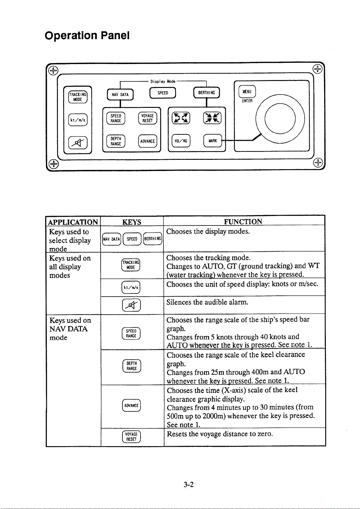


5. NAV DATA MODE OPERATION
This section describes the o perat ion on the NAV DATA MODE as
well as the readings on the screen.
8
23
Basic Operation
TRACKING MODE
kt/m/s
SPEED RANGE
DEPTH RANGE
Internal
You may operate this mode with the following key switches.
Chooses the tracking mode for ship’s speed measurement:
Ground, Water or Auto. Normally select “Auto” for automatic
changeover to “Water” when the ground tracking is not attainable.
The Ground tracking is normally attainable up to a 200m deep
bottom.
Select the unit of ship’s sp eed display.
Chooses the range scale of ship’s speed bargraph.
Chooses the depth scale of the under-keel clearance graphic
display.
5-1


3. Ship’s Heading
4. Drift
5. Tran sv er se Speed
at Bow
6. Longitudinal Speed
7. Tran sv er se Speed
at Stern*
8. Speed Graph
9. Echo Monito r
Heading data derived from gyrocompass is indicated.
0° is displayed in the case of no gyrocompass connection.
Dr ift (angle between ship’s heading a nd ship’s course) is displayed.
See the illustration on page 5-2.
Value over-the ground or through-the-water is displayed as
determined by the tracking mode.
Value over-the-ground or through-the-water is displayed as
determined by the tracking mode.
Value over-the-ground or through-the-water is displayed as
determined by the tracking mode.
* Rate-of-turn gyro or gyrocompass required. When no connected,
transverse speed at the position of the tr ansducer is indicated.
Ship’s speed bar graphs for ite m 5,6 and 7.
Monitors received echoes for past three minutes, showing echo
type as follows.
• Ground tracking echo: Green
• Water tracking echo: Blue
• No echo: Background color
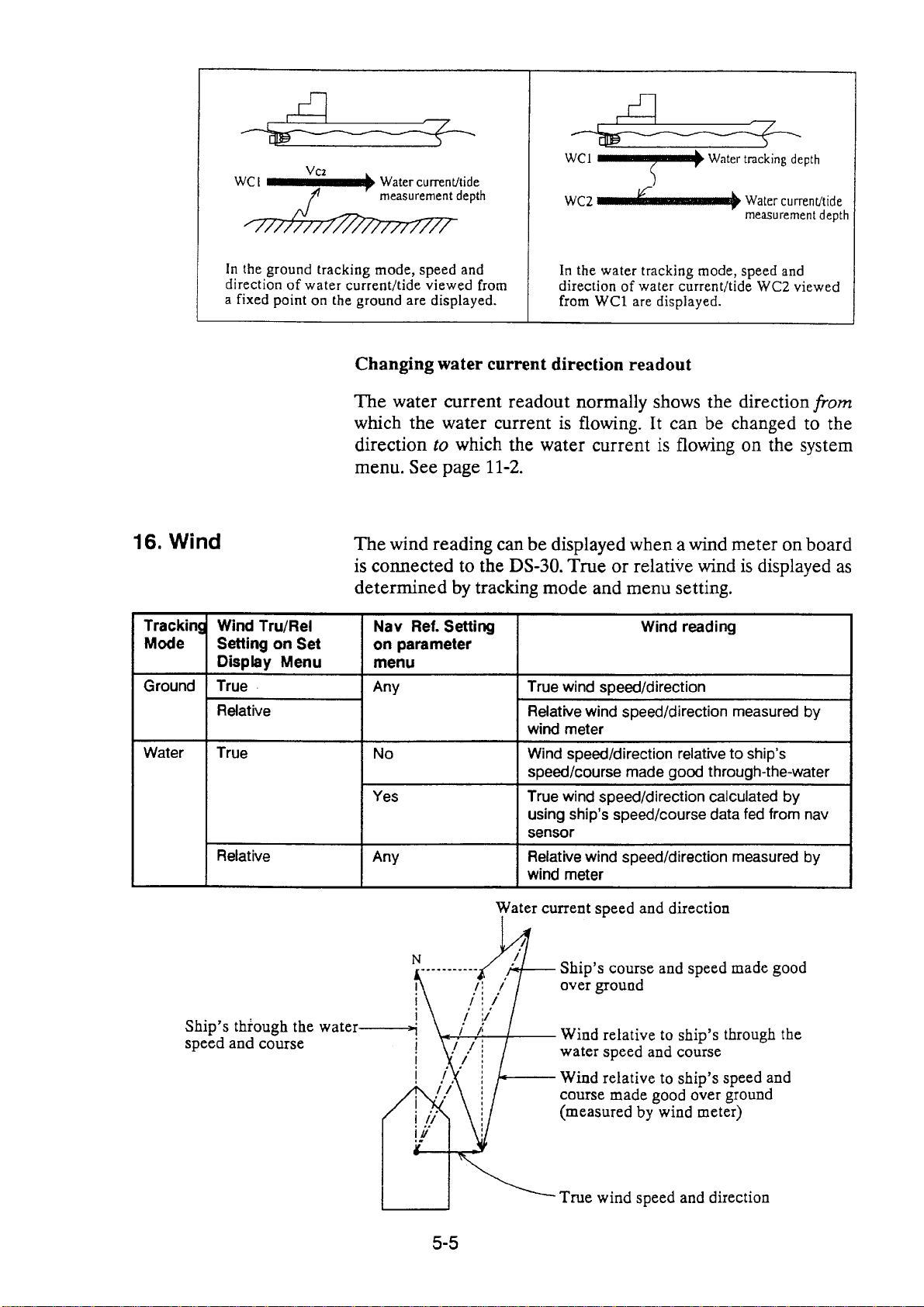
10. Trackin g Mode
Press the TRACKING MODE key to change the tracking mode.
Three modes are available:
• Auto: Automatic changeover
bet w een g rou nd tac king a nd water
tracking.
• Ground: Ground tracking
• Wa ter: Wate r tracking
5-3


distance run between ports and the total distance the to tal distance
run fro m p ort “A” to “D” .
22. Graphic
display
23. Rate Sensor
Resetting voyage distance
To reset the voyage to zero, press the VOYAGE RESET key.
Resetting voyage distance
The total distance can be set to any desired value on the initial
setup menu. See page 9-12.
Selecting unit of distance
You may select the unit of distance “nm” (nautical mile) or “km”
on the system menu. See page 11-1.
The drift (4), water current (15), and relative wind (16) are
graphically displayed.
The rate sensor chosen in the INT. SET UP menu is displayed:
Internal, Ext ernal ROT or External HDG.
5–8
 Loading...