

FUNAI 29A-650, 29A-750, 29A-654, 29A-754 Owner's Manual
Printed in China
1VMN20023A
HG451ED***
EN
VIDEO CASSETTE RECORDER
Owner’s Manual
PAL
CONGRATULATIONS ON YOUR NEW PRODUCT!
PLEASE KEEP THIS GUIDE IN A SAFE PLACE
Important information
Should any problems or defects occur in this product, please contact the vendor via the
mail address below or by phone BEFORE contacting the shop where it was purchased.
Follow these three points
to receive help from our technical specialists:
1. Before calling, please read this user guide thoroughly.
2. Check our website at www.dangaard-electronics.com, where FAQ, various
drivers, manuals, software etc are available for free download.
3. Before calling, please have valid proof of purchase, model type, serial
number and a precise description of the problem ready!
Service Hotline Mail: service@dangaard-el.com
Service Hotline Telephone: Denmark: +45 7230 3535
Germany: +49 180 5 777 4475
*
Telephone opening hours are Monday-Friday from 09.00-15.00
If we are unable to solve the problem via the Hotline and the product has to be returned to the dealer, please
note that the product, its original packaging, any accessories and proof of purchase must be handed to the
dealer before the product can be accepted for repair handling.
Brand: FUNAI Model no.: 29A-650 29A-654 (VPS/PDC)
29A-750 29A-754 (VPS/PDC)
29A-650(EN).fm Page 1 Wednesday, October 27, 2004 10:40 AM
2 EN
Safety Information
WARNING:
• Live parts inside. Do not remove any screws.
• To avoid fire or electric shock, do not expose
this unit to rain or moisture.
• Dangerous voltage inside
Precautions
• Use only cassettes with the VHS mark with this VCR.
• Do not attempt to open the cabinet. There are no parts you
can service inside. Refer all servicing to qualified service
personnel.
• Slots and openings in the cabinet and the sides or bottom
are provided for ventilation. To ensure reliable operation
and to protect the unit from overheating, these openings
must not be blocked or covered.
• Avoid installation in enclosed spaces such as bookcases
unless proper ventilation is provided.
• Keep the unit away from radiators and other heat sources.
• Avoid use near strong magnetic fields.
• Do not push objects of any kind into the VCR through the
cabinet slots or openings as they could touch electrically
live parts or short circuit parts resulting in a fire or electric
shock.
• Never spill liquid on this unit. If liquid is spilled and
penetrates into the unit, consult qualified service personnel.
• Use this unit in a horizontal (flat) position only.
• Before attempting to operate the unit, make sure that the
timer recording mode is “OFF”.
• This product is in Stand-by mode when it turns off while
the power cord is connected.
Power Supply
The main power supply is engaged when the power cord plug
is plugged in a 220-240V, 50Hz, AC outlet. To operate the
unit, press
FUNCTION to turn on the unit. (PWR indicator on
the VCR comes on.)
Dew Warning
Moisture condensation may occur inside the unit when it is
moved from a cold place to a warm place, after heating up a
cold room, or under conditions of high humidity. Do not use
the VCR for at least 2 hours until it is dry inside.
Positioning
Do not place the VCR directly on top of, or underneath, your
TV set. Ensure that there is at least 20 cm between the VCR
and the TV set, and that air can circulate freely through the
ventilation openings of the VCR.
Before Using This Product
Video Cassette Tape
This VCR will operate with any cassette that bears the VHS
mark. For best results, we recommend the use of high-quality
tapes. Do not use poor quality or damaged tapes.
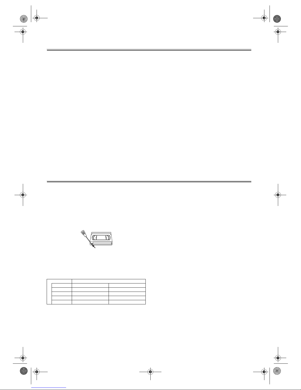
You can prevent accidental erasing of a recording by breaking
off the erase-prevention tab on the back edge of the cassette. If
you decide to record on the tape again, cover the hole with
plastic tape.
Two Different Tape Speeds
Before recording, select the tape speed : SP mode (Standard
Play) or LP mode (Long Play). The table below shows the
maximum recording/playback time using E-60, E-120, E-180
or E-240 tapes in each mode.
TV Colour System
Different countries use different television colour systems.
Tapes recorded in the PAL or NTSC system can be played
back on this unit. Usually, the picture on the TV screen will
be in black and white when you play back a tape that is
recorded in a different colour system.
Tapes recorded in the NTSC system can be played back on
this unit and a PAL system TV set. This feature is only
available in the SP mode. When playing back such tapes, the
picture may roll up or down, shrink vertically and black bars
may appear both at the top and bottom of the screen. Adjust
the vertical hold control on your TV, if the TV features this
control.
Tape Type Recording/Playback Time
Tape Speed SP Mode LP Mode
E-60 1 hour 2 hours
E-120 2 hours 4 hours
E-180 3 hours 6 hours
E-240 4 hours 8 hours
Ta b
29A-650(EN).fm Page 2 Wednesday, October 27, 2004 10:40 AM
3 EN
Table of Contents
Safety Information .............................................................................................................................................2
Before Using This Product ................................................................................................................................2
Installation .........................................................................................................................................................5
Basic Operation ................................................................................................................................................9
Advanced Operations .....................................................................................................................................10
Maintenance ...................................................................................................................................................14
Troubleshooting Guide ...................................................................................................................................15
Specifications ..................................................................................................................................................15
Declaration of Conformity ...............................................................................................................................16
Features
•Hi-Fi System
• Automatic Operations
• On Screen Display
• Auto Repeat Playback
• Picture Select
• One Touch Recording
•Parents Lock
• Auto Return
• Timer Recording
• Auto Head Cleaner
•NTSC Playback
• Auto Clock Setting (29A-654/29A-754)
• VPS/PDC (29A-654/29A-754)
• Quick-Find
•Index/Time Search
• Slow Motion
• AUDIO/VIDEO in jacks
• AUDIO OUTPUT L/R jacks
Supplied Accessories
• Remote control
• Two R6 batteries
• RF cable
Important Copyright Information
Unauthorised recording or use of broadcast television
programming, video tape, film or other copyrighted material
may violate applicable copyright laws. We do not take
responsibility for the unauthorised duplication, use, or other
acts which infringe upon the rights of copyright owners.
A Note About Recycling
This product’s packaging materials are recyclable and can be
reused. Please dispose of any materials in accordance with your
local recycling regulations.
Batteries should never be thrown away or incinerated but
disposed of in accordance with your local regulations
concerning chemical wastes.
Model/Serial Number
This appliance has a serial number located on the rear panel.
Please note down the model number and serial number and
retain the information for your records.
Model number:
Serial number:
29A-650(EN).fm Page 3 Wednesday, October 27, 2004 10:40 AM
4 EN
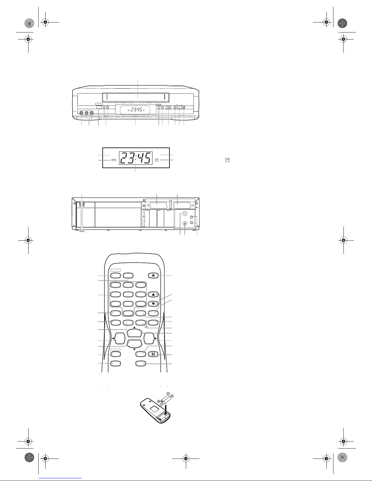
Description of Controls
Front Panel
1. Cassette compartment
2. F.FWD (Fast Forward) button
3. PLAY button
4. REW (Rewind) button
5. STOP/EJECT button
6. REC/OTR button
7. AUTO RETURN button
8. Indicator (See below.)
9. CHANNEL (K/L) buttons
10. FUNCTION button
11. AUDIO in jacks
12. VIDEO in jack
Indicator
13. PWR (Power) indicator
14. REC (Record) indicator
15. (Timer) indicator
16. Clock/RF OUT Channel indicator
17. Cassette indicator
Rear Panel
18. Power cord
19. AV2 (DECODER) socket
20. AV1 (TV) socket
21. AUDIO OUTPUT L/R jacks
22. RF OUT socket
23. AERIAL socket
Remote Control
1. FUNCTION button
2. AUDIO SELECT button
3. number buttons
4. MENU button
5. DISPLAY button
6. REW/
s button
7. STOP/
L button
8. REC/OTR button
9. QUICK-FIND button
10. SEARCH MODE button
11. PAUSE/STILL button
12. SPEED/SYSTEM button
(Only the function of SPEED is available
for this VCR.)
13. F.FWD/
B button
14. PLAY/
K button
15. TAPE COUNTER RESET button
16. TAPE COUNTER MEMORY button
17. SLOW button
18. CHANNEL (
K/L) buttons
19. EJECT button
To insert the batteries:
Install two R6 batteries matching the
polarity indicated inside the battery
compartment.
Caution
Do not mix old and new batteries. (Also never mix alkaline
batteries with manganese batteries.)
CHANNEL
L-AUDIO-RVIDEO
FUNCTION
AUTO RETURN
PLAY F.FWDREW
STOP/EJECTREC/OTR
REC
PWR
12
11 10
987
65
432
1
13
1517
16
14
REC
PWR
AV2 (DECODER) AV1 (TV)
AUDIO
OUTPUT
AERIAL
RF OUT
R
L
2019
2223 21
18
PLAY
STOP
REW
F.FWD
0
7
8
9
6
5
4
3
2
1
FUNCTION
EJECT
AUDIO
SELECT
CHANNEL
SLOW
TAPE COUNTER
MEMORY
RESET
MENU
DISPLAY
REC/OTR
QUICK-FIND
SEARCH MODE
SPEED/
SYSTEM
PAUSE/STILL
1
3
2
18
19
4
6
8
7
9
16
17
13
12
14
11
10
15
5
*
*
* These buttons do not function for this VCR.
29A-650(EN).fm Page 4 Wednesday, October 27, 2004 10:40 AM
5 EN
Installation
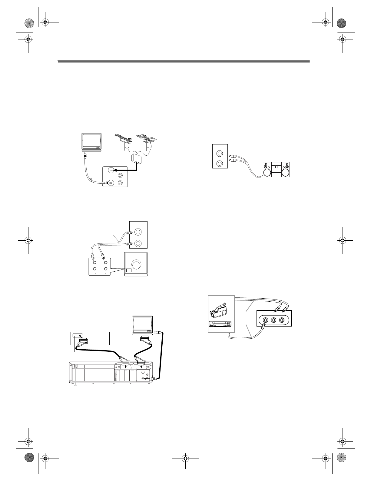
Connecting the VCR
Basic Connection
1) Disconnect the TV’s power cord from the AC outlet.
2) Disconnect the VHF/UHF TV aerial coaxial cable from
the TV.
3) Connect the VHF/UHF TV aerial coaxial cable to the
VCR.
4) Connect the VCR to the TV using the coaxial cable.
5) Plug the power cords of the VCR and TV into the AC
outlets.
Note: If your TV has AUDIO input jacks, you may connect
the AUDIO OUTPUT L/R jacks on the back of this
VCR to the AUDIO input jacks on your TV.
Other Connections
Euro Scart (AV) Sockets
Your VCR is provided with two Scart sockets which you may
connect to other external devices with Scart sockets. We
recommend this connection to ensure a better audio and
picture quality.
Euro Scart cables are obtainable at your dealer.
AV1 (TV) Connection to TV
If your TV has Scart sockets, you may connect your VCR’s
AV1 (TV) scart socket to the Scart socket on the back of your
TV. Please see the instruction manual for your TV.
Note: You may connect the VCR to your audio amplifier.
1) Prepare an audio cable (not supplied).
2) Switch off your audio amplifier.
3) Insert one end of the audio cable into the corresponding
red and white AUDIO OUTPUT L/R socket at the back
of the video recorder and the other end into the
corresponding audio input socket at the audio amplifier.
AV2 (DECODER) Connection for Other External Devices
The second Scart socket AV2 (DECODER) is designated for
other external devices, e.g. decoder, another VCR, video
camera and so on.
Note: If you want to connect a TV with Scart socket to your
VCR, the TV must be connected to the VCR through
AV1 (TV). A connection to AV2 (DECODER) will not
function correctly.
AV Front Terminals
When you copy a video tape, or watch a programme recorded
on an another source, use the AUDIO/VIDEO input jacks on
the front panel of the VCR.
Note: When you connect a monaural VCR (another source)
to this VCR, connect the audio output jack of the
monaural VCR (another source) to the AUDIO L jack
of this VCR. The audio signal will be recorded in both
L and R channel equally.
External Input Mode
To receive the signal from an external source (decoder, video
camera, another VCR, etc.), connect the source to the AV2
(DECODER) socket, and press CHANNEL (K/L) or enter
“002” with the
number buttons. “AV2” appears on the TV
screen. If you use the AV1 (TV) socket, press
CHANNEL (K/L) or enter “001” with the number buttons.
“AV1” appears on the TV screen.
If you use the front AUDIO/VIDEO input jacks, press
CHANNEL (K/L) or enter “003” with the number buttons.
“AV3” appears on the TV screen.
RF OUT
AERIAL
L
R
AUDIO
OUTPUT
R
VHF/UHF
MIXER
to AERIAL
to RF OUT
(Back of the unit)
to aerial socket
(TV)
UHF
VHF
[A/V television]
[Back of the VCR]
Audio/Video cable
(not supplied)
IN
AUDIO
LR
L
R
AUDIO
OUTPUT
AV2 (DECODER) AV1 (TV)
AUDIO
OUTPUT
AERIAL
RF OUT
R
L
AV1 (TV)
to 21-Pin
to 21-Pin Scart Jack
Decoder (Not supplied)
(TV)
to RF OUT
to aerial
socket
Scart Jack
[Back of the VCR]
L
R
AUDIO
OUTPUT
VIDEO L AUDIO R
[Front of the VCR]
etc.
To the audio
output jack
[Another source]
To the video
output jack
Audio/Video
cables
(not supplied)
29A-650(EN).fm Page 5 Wednesday, October 27, 2004 10:40 AM
 Loading...