

FULTON Endura+ Series, EDR+ 2500, EDR+ Series, EDR+ 3000, EDR+ 4000 Installation And Operation Manual
...Page 1
INSTALLATION AND
OPERATION MANUAL
Endura+ (EDR+)
Condensing Hydronic Boilers
2,500,000 - 6,000,000 BTU/HR
Serial/ National
Board Number
Model
Fulton Order
Owner
Site Name
Date
EDRP-IOM-2019-0212
Page 2

Page 3

EDRP-IOM-2019-0212 TABLE OF CONTENTS
Introduction 1-1
Overview .............................................................................................................. 1-2
Warnings & Cautions ............................................................................................1-2
Disclaimers and Local Codes ................................................................................ 1-2
Installation 2-1
Product Overview ................................................................................................. 2-2
Massachusetts Installations ................................................................................. 2-2
Placement & Rigging ........................................................................................... 2-3
Clearances and Serviceability .............................................................................. 2-5
Install Boiler Trim ................................................................................................. 2-5
Install Water Piping ..............................................................................................2-6
VARIABLE PRIMARY PIPING ARRANGEMENT ............................................................................27
PRIMARYSECONDARY PIPING ARRANGEMENT ......................................................................210
Meet Water Chemistry Requirements ................................................................ 2-11
Fill the Boiler with Water .................................................................................... 2-12
Gas Supply Piping .............................................................................................. 2-12
PREVENT OXYGEN CONTAMINATION ........................................................................................212
ELIMINATE SYSTEM AIR ............................................................................................................212
INLET GAS PRESSURE ................................................................................................................212
LINE GAS PRESSURE REGULATION ............................................................................................213
GAS PIPING INSTALLATION .......................................................................................................213
COMPONENTS REQUIRING VENTILATION TO THE OUTDOORS .................................................216
Install Condensate Drain Trap .............................................................................2-16
SINGLE BOILER DRAIN TRAP .....................................................................................................216
MULTIPLE BOILERS SHARING A COMMON DRAIN TRAP .........................................................219
Install pH Neutralization Kit ............................................................................... 2-21
Venting Requirements ....................................................................................... 2-21
Combustion Air Intake .......................................................................................2-22
COMBUSTION AIR SUPPLY FROM THE BOILER ROOM ..............................................................223
AIR PIPED FROM OUTSIDE BOILER ROOM ................................................................................224
Air Filter .............................................................................................................. 2-25
Flue Gas Exhaust Venting ................................................................................... 2-25
Common Venting Layouts for Endura+ ............................................................. 2-28
Venting Terminations ......................................................................................... 2-28
WALL THIMBLE INSTALLATION .................................................................................................232
ROOF VENT TERMINATION .........................................................................................................232
SIDE WALL VENT TERMINATION ................................................................................................232
Removing an Existing Boiler ............................................................................. 2-33
Assembly of Fulton Multi-Skid Systems............................................................. 2-34
Relocating the EDR+ 6000 Panel Box to Opposite Side ....................................2-35
Electrical Connections and Devices .................................................................... 2-36
JUNCTION BOX LOCATIONS FOR FIELD WIRING .......................................................................240
ELECTRICAL AND CONTROLS OPTIONS .....................................................................................240
Operation 3-1
Perform Pre-Start-Up Inspection ......................................................................... 3-2
Fill and Purge the System..................................................................................... 3-2
Commission The Boiler ......................................................................................... 3-3
SYSTEM DESIGN AND BOILER OPERATION .................................................................................33
TURNDOWN .................................................................................................................................34
Operation Modiers ........................................................................................... 3-4
Siemens LMV3 Control ......................................................................................... 3-4
BEFORE MODIFYING LMV PARAMETERS ....................................................................................36
STEPS TO ENTER PARAMETERS ...................................................................................................36
ADJUSTING FUEL/AIR CURVE .....................................................................................................36
MANUAL CONTROL MANUAL REQUEST FOR OUTPUT ............................................................38
PARAMETER BACKUP ..................................................................................................................39
PARAMETER RESTORE ...............................................................................................................310
Using the Endura+ PURE Control™ Interface .................................................... 3-12
NAVIGATION ...............................................................................................................................312
Endura+ PURE Control™ Menu Screen Functions ............................................. 3-14
BOILER CONTROL .......................................................................................................................314
LEAD/LAG ...................................................................................................................................316
PID CONTROL .............................................................................................................................317
SETPOINT ...................................................................................................................................319
SCHEDULING .............................................................................................................................320
TRENDING ..................................................................................................................................320
ADMIN ........................................................................................................................................320
Commissioning Mode ........................................................................................ 3-22
Perform Test of Limit Controls ........................................................................... 3-23
Perform Test of Low Gas Pressure Switch .......................................................... 3-23
Perform Test of High Gas Pressure Switch .......................................................... 3-23
General Operation of the Boiler ......................................................................... 3-23
Maintenance 4-1
General ................................................................................................................. 4-2
Daily Maintenance and Inspection Schedule ...................................................... 4-2
Weekly Maintenance and Inspection Schedule .................................................. 4-2
Monthly Maintenance and Inspection Schedule ................................................. 4-3
Replacing the Combustion Air Inlet Filter .......................................................... 4-3
Replacing or Updating the Boiler Control ...........................................................4-3
Annual Maintenance and Inspection Schedule ................................................... 4-4
O Compensation Measurement .......................................................................... 4-4
Removing, Inspecting and Cleaning Burner ........................................................ 4-5
Inspecting the Pilot Ignition Assembly ................................................................ 4-7
After All Repairs and Maintenance ...................................................................... 4-7
Troubleshooting ................................................................................................. 4-10
Questions? Please Contact Your Local Manufacturer’s Representative
0-1
Page 4

TABLE OF CONTENTS EDRP-IOM-2019-0212
0-2
© Fulton Group N.A., 2019
Page 5

INTRODUCTION
INTRODUCTION
1
INSTALLATION
2
OPERATION
MAINTENANCE
3
4
Questions? Please Contact Your Local Manufacturer’s Representative
1-1
Page 6

INTRODUCTION EDRP-IOM-2019-0212 SECTION 1
Overview
Prior to shipment, the following inspections and tests are
made to ensure the highest standards of manufacturing for
our customers:
Material inspections
Manufacturing process inspections
American Society of Mechanical Engineers (ASME)
welding inspection
ASME hydrostatic test inspection
Electrical components inspection
Operating test
Final engineering inspection
Crating inspection
This manual is provided as a guide to the correct operation
and maintenance of your Fulton equipment, and should be
read in its entirety and be made permanently available to the
sta responsible for the operation of the boiler. It should not,
however, be considered as a complete code of practice, nor
should it replace existing codes or standards which may be
applicable. Fulton reserves the right to change any part of
this installation, operation and maintenance manual.
Installation, start-up, and maintenance of this equipment
can be hazardous and requires trained, qualied installers
and service personnel. Trained personnel are responsible
for the installation, operation, and maintenance of this
product, and for the safety assurance of installation,
operation, and maintenance processes. Do not install,
operate, service or repair any component of this
equipment unless you are qualied and fully understand
all requirements and procedures. Trained personnel refers
to those who have successfully completed Fulton Service
School training specic to this product.
Warnings & Cautions
WARNINGS and CAUTIONS appear in various chapters of this
manual. It is critical that all personnel read and adhere to all
information contained in WARNINGS and CAUTIONS.
WARNINGS must be observed to prevent serious injury
or death to personnel.
CAUTIONS must be observed to prevent damage
or destruction of equipment or loss of operating
eectiveness.
All Warnings and Cautions are for reference and guidance
purposes, and do not substitute for required professional
training, conduct, and strict adherence to applicable
jurisdictional/professional codes or regulations.
Disclaimers and Local Codes
Installation of the equipment shall conform to all the
requirements or all national, state and local codes established
by the authorities having jurisdiction or, in the absence
of such requirements, in the US to the National Fuel Gas
Code ANSI Z223.1/NFPA 54 latest edition, and the specic
instructions in this manual. Authorities having jurisdiction
should be consulted prior to installation.
When required by local codes, the installation must conform
to the American Society of Mechanical Engineers Safety Code
for Controls and Safety Devices for Automatically Fired Boilers
(ASME CSD-1).
The boiler heat exchanger is manufactured and stamped
in accordance with ASME Boiler and Pressure Vessel Code,
Section IV for a maximum allowable working pressure
and operating temperature of 160 psig and 210°F (99°C)
respectively.
When working on this equipment, observe all warnings,
cautions, and notes in literature, on stickers and labels, and
any additional safety precautions that apply. Follow all safety
codes and wear appropriate safety protection. Follow all
jurisdictional codes and consult any jurisdictional authorities
prior to installation.
1-2
© Fulton Group N.A., 2019
Page 7

INSTALLATION
INTRODUCTION
1
INSTALLATION
2
OPERATION
MAINTENANCE
3
4
Questions? Please Contact Your Local Manufacturer’s Representative
2-1
Page 8

INSTALLATION EDRP-IOM-2019-0212 SECTION 2
! WARNING
All information in this manual is for
reference and guidance purposes,
and does not substitute for required
professional training, conduct,
and strict adherence to applicable
jurisdictional/professional codes and
regulations.
4 CAUTION
The standard conguration for
this boiler is certied for indoor
installation only.
This boiler is not designed for use in
systems where water is continuously
replenished. The warranty is valid for
closed loop systems only.
Fulton cannot be held responsible
for the selection, engineering,
installation, or sizing of any
additional equipment or components
of the hydronic heating system.
Always verify gas type and pressure
ratings for your boiler by viewing the
boiler name plate.
Product Overview
Prior to the performance of installation, operation, or maintenance procedures,
personnel should become familiar with the equipment (Table 1 and Figure 1) and
its components.
The Fulton Endura+ hot water boiler is an automatic, fuel-red, ultra higheciency boiler. The boiler can either have combustion air ducted directly from
the outdoors or utilize conventional combustion air intake and ue methods.
The boiler is capable of sidewall venting when the appropriate venting materials
are used, and when permitted by local code requirements.
The Fulton Endura+ boiler is ETL-certied to Underwriters Laboratories (UL)
Edition 7 UL Standard for Safety Commercial-Industrial Gas Heating Equipment,
and bears the H stamp. The boiler heat exchanger is manufactured and stamped
in accordance with American Society of Mechanical Engineers (ASME) Boiler and
Pressure Vessel Code, Section IV for a maximum allowable working pressure and
temperature of 160 psi and 210°F (99°C) respectively. All Endura+ boilers are
hydrostatically tested, test red and shipped as a complete packaged unit.
Fuel, water and electrical connections are similar to other boilers of this type.
Please be aware of which burner and control conguration has been designed
specically for your application.
This Endura+ boiler is to be installed as part of a hydronic heating system. A
qualied engineer must be consulted for the selection of the equipment and
components of the heating system. Various system conditions can result in
incorrect heat distribution to users of the heating system.
Each Endura+ Boiler is supplied with the following:
Integrated combustion supervision and temperature operating control
Operating and high temperature probe(s) in pressure vessel
Low water probe(s) in pressure vessel
2-2
ASME safety relief valve
Installation and Operation Manual
Test re report
Wiring diagram
Temperature and pressure (T&P) gauge
The customer should examine the equipment for any damage. It is the
responsibility of the installer to ensure all parts supplied with the equipment are
tted in a correct and safe manner.
Massachusetts Installations
Boilers installed in Massachusetts must have the following:
A gas pressure regulator installed upstream of the gas train provided by
the manufacturer.
Two safety shuto valves, in series, one of which is of the type
incorporating a valve seal overtravel interlock when the maximum ring
rate per combustion chamber exceeds 5,000,000 BTU/hour.
© Fulton Group N.A., Inc. 2019
Page 9

SECTION 2 EDRP-IOM-2019-0212 INSTALLATION
Placement & Rigging
Proper placement of your Fulton product is essential. Attention paid to
the following points will save a great deal of diculty in the future. Correct
placement is the rst step to trouble-free installation, operation, and
maintenance.
Adhere to the following for placement and rigging:
1. Check building specications for permissible oor loading. Use Table 1 for
unit reference.
2. Conform to all the requirements of all national, state and local codes
established by the authorities having jurisdiction and/or the U.S. to the
National Fuel Gas Code, latest edition. Authorities having jurisdiction
should be consulted before installations are made. Where required by local
codes, the installation must conform to American Society of Mechanical
Engineers Safety Code for Controls and Safety Devices for Automatically
Fired Boilers (ASME CSD-1).
3. Since an external electrical source is utilized, the boiler, when installed,
must be electrically ground in accordance with the National Electric Code,
American National Standards Institute (ANSI) National Fire Protection
Association (NFPA) 70, latest edition.
4. Standard Endura+ boilers are certied for indoor installation only, where
room conditions do not expose the boiler to temperatures below 32°F
(0°C) or exceeding 120°F (48.9°C).
5. Install so that all system components are protected from water (dripping,
spraying, rain, etc.) and debris (dry wall dust, insulation particles, etc.)
during boiler operation and service.
6. Install on a level, non-combustible surface. Concrete is strongly
recommended. The surface must be elevated a minimum of 4” (102 mm)
above the oor. The use of shims may be required to ensure the boiler is
level. Do not install the boiler on springs.
7. Provide combustion and ventilation air in accordance with applicable
provisions of local building codes or: USA – NFPA 54/ANSI Z223.1, Section
5.3, Air for Combustion and Ventilation.
8. Locate the boiler so that the air supply and exhaust piping between the
boiler and outside wall/roof are within the draft pressure requirements for
horizontal or vertical venting. See Clearances and Serviceability section
of this manual.
! WARNING
All information in this manual is for
reference and guidance purposes,
and does not substitute for required
professional training, conduct,
and strict adherence to applicable
jurisdictional/professional codes and
regulations.
Competent personnel in accordance
with all applicable local codes
should carry out the installation
of the Fulton equipment. All state
and jurisdictional codes beyond the
scope of the applicable ASME Boiler
and Pressure Vessel Codes, for its
corresponding classication, should
be followed in all cases. Jurisdictional
authorities must be consulted prior to
installation.
A competent rigger experienced in
handling heavy equipment should
handle rigging your equipment into
position.
The equipment must be installed on a
non-combustible surface.
Failure to provide required and
safe access to the equipment
could impede commissioning and
maintenance. Service technicians
are instructed not to commence
commissioning if hazardous
conditions exist.
Failure to provide proper minimum
clearances between equipment and
combustible materials may result in
re.
4 CAUTION
Questions? Please Contact Your Local Manufacturer’s Representative
Do not allow weight to bear on
equipment components to prevent
damage.
Do not use to directly heat a swimming
pool.
2-3
Page 10

INSTALLATION EDRP-IOM-2019-0212 SECTION 2
TABLE 1 BOILER DIMENSIONS AND OPERATING REQUIREMENTS
Specications EDR+ 2500 3000 4000 5000 6000
Rated Input Capacity1 MBH 2,500 3,000 4,000 5,000 6,000
Minimum Input at Low Fire MBH 20 0 200 400 400 400
Output at BTS-2000 conditions MBH 2,420 2,889 3,784 4,725 5,75 4
Fuel Consumption at Capacity SCFH 2,475 2,970 3,960 4,950 5,941
Nat. Gas Pressure Required W.C. 4 - 14 4 - 14 4 - 28 8 - 28 8 - 28
Variable Water Flow GPM 25 - 350 25 - 350 75 - 700 75 - 700 75 - 700
Full Load Amps (460/3/60) AMP 15.0 15.0 15.0 2 3.0 23.0
Typical High Fire Amps (460/3/60) AMP 6.10 9. 75 9.0 10.0 15.6
Typical Low Fire Amps (460/3/60) AMP 0.75 0.75 1. 0 0.9 0.9
Water Content GAL 80 80 18 0 180 18 0
Dry Weight LBS 2,600 2,600 5,039 5,087 5, 092
Operating Weight LBS 3,267 3, 267 6,54 0 6,588 6,593
Dimensions EDR+ 2500 3000 4000 5000 6000
A. Boiler Width IN 30 30 34 34 34
B. Boiler Height IN 80 80 79 79 79
C. Boiler Depth IN 73 73 116. 2 116. 2 116. 2
D. Flue Gas Stack (dia) IN 8 8 12 14 14
E. Combustion Air Inlet (dia) IN 10 10 12 12 12
F. Water Inlet/Outlet (dia) IN 4 4 6 6 6
Minimum Clearance EDR+ 2500 3000 4000 5000 6000
G. Front IN 36 36 36 36 36
H. Rear IN 24 24 36 36 36
I. Top IN 18 18 18 18 18
J. Sides IN 1; 24 1; 2 4 1; 24 1; 24 1;24
Endura+ boilers may be operated up to 10,000 feet elevation, and up to 1,000 feet elevation at 80˚ F without de-rate. Consult your Fulton Representative for capacities at higher elevation.
Applies to natural gas with a caloric value of 1,010 BTU per FT3.
Standard natural gas congurations only. Alternate or custom congurations may have dierent requirements; always review the boiler nameplate before installation.
Standard electrical congurations only. Alternate or custom congurations may have dierent requirements; always review the boiler nameplate before installation.
An appliance adapter is required (optional factory trim; supplied only when ordered).
24-inch (610mm) clearance is required on one side to facilitate and expedite maintenance and any advanced troubleshooting.
NOTE: Specications and dimensions are approximate and for reference only. Fulton practices continuous product improvement and reserves the right to change specications and/or dimensions without notice.
TOP VIEW
D
E
J
I
F
J
B
A C
FRONT VIEW SIDE VIEW
FIGURE 1 ENDURA+ HYDRONIC BOILER SERVICE CLEARANCE
G
H
2-4
© Fulton Group N.A., Inc. 2019
Page 11

SECTION 2 EDRP-IOM-2019-0212 INSTALLATION
DRAWING NUMBER
REV
DESCRIPTION:
DRAWN BY:
CHECKED BY:
B.O.M. REVIEW
MECH. ENG:
ELEC. ENG:
APPROVED BY:
JOB NUMBER:
PROJECT NAME:
PROJECT MANAGER:
This design and drawings
are proprietary and are the
exclusive property of
Fulton Group N.A., Inc.
The corporation does not
permit their use except
with prior written consent.
The items shown in this
drawing may be covered by
one or more patents of
Fulton Group N.A., Inc.
1 OF 1
THIRD ANGLE PROJECTION
Fulton Group N.A., Inc
972 Centerville Road
Pulaski, New York USA 13142
UNLESS OTHERWISE NOTED
DIMENSIONS ARE IN INCHES
R
SHEET 1 OF 1
(1) PLACE DEC.
` 0.03
(2) PLACE DEC.
` 0.015
(3) PLACE DEC.
` 0.005
ANGLE
` 0.5 DEG
SURFACE FINISH
250 MICRO-INCHES
TOLERANCES
FRACTION &
WHOLE VALUE
`1/8
G-36-100018 -
ENDURA+ MULTIPLE BOILER COMMON EXHAUST
VENTING DIAGRAM
B. PALMER
K.D.B.
4/11/2016
4/19/2016
SEE NOTE 8
Clearances and Serviceability
Adhere to the following for clearances and serviceability:
1. All local and national codes (NFPA, ANSI, UL, CSA,
ASME) must be followed for proper clearances and
serviceability for your boiler or heater. Authorities
having jurisdiction should be consulted before
installations are made.
2. Appropriate front, back, side and top clearances must
be maintained (Figure 1) to allow access around the
equipment to facilitate maintenance and a safe work
environment, as follows:
» A 1-inch (25.4 mm) side clearance is acceptable
between a pair of boilers. Custom congurations
may not allow 1-inch (25.4 mm) side clearance.
» 24-inch (610 mm) clearance is required on one
side to facilitate and expedite maintenance and
any advanced troubleshooting.
3. Ensure all labels on the boiler will be fully visible for
maintenance and inspection.
4. Do not place or install any boiler room accessories, or
other components, on the Endura+ cabinet panels.
Install Boiler Trim
Each Endura+ boiler is supplied with a safety relief valve
sized in accordance with ASME requirements. Adhere to the
following installation requirements:
TABLE 2 CONT. SAFETY RELIEF VALVE INLET AND OUTLET SIZES
Model Trim Pressure
PSI (kPa)
EDR+ 4000
EDR+ 5000
EDR+ 6000
30 (206.84) 2 (50.8) 2 1/2 (63.5)
60 (413.69) 1 1/2 (38.1) 2 (50.8)
100 (689.48) 1 1/2 (38.1) 1 1/2 (38.1)
125 (861.84) 1 1/4 (31.8) 1 1/4 (31.8)
Inlet Size
inch (mm)
Outlet Size
inch (mm)
160 (1103.16) 1 (25.4) 1 1/4 (31.8)
2. The discharge pipe must:
» Not have a diameter less than the full area of the
valve outlet.
» Be as short and straight as possible and so
arranged as to avoid undue stress on the valve.
» Be supported by means other than the safety
valve itself.
» Be piped to avoid danger of scalding
personnel.
NOTE: Each boiler is supplied with a pressure-temperature
gauge to be installed in the outlet piping section of the boiler.
Gauge must not be isolated from the boiler by any valve.
Note: Valve is shipped loose and must be
installed by the contractor.
1. The safety relief valve (Figure 2) must:
» Be connected to the coupling located in the top
of the boiler.
» Be installed in the upright vertical position.
NOTE: Safety relief valve size is determined by trim pressure
and is supplied in the trim kit. For inlet and outlet sizes, see
Table 2.
TABLE 2 SAFETY RELIEF VALVE INLET AND OUTLET SIZES
Model Trim Pressure
PSI (kPa)
EDR+ 2500
EDR+ 3000
Questions? Please Contact Your Local Manufacturer’s Representative
30 (206.84) 1 1/2 (38.1) 2 (50.8)
60 (413.69) 1 1/4 (31.8) 1 1/2 (38.1)
100 (689.48) 1 (25.4) 1 1/4 (31.8)
125 (861.84) 1 (25.4) 1 1/4 (31.8)
160 (1103.16) 3/4 (19.1) 1 (25.4)
Inlet Size
inch (mm)
Outlet Size
inch (mm)
FIGURE 2 SAFETY VALVE INSTALLATION LOCATION
2-5
Page 12

INSTALLATION EDRP-IOM-2019-0212 SECTION 2
! WARNING
All information in this manual is for
reference and guidance purposes,
and does not substitute for required
professional training, conduct,
and strict adherence to applicable
jurisdictional/professional codes and
regulations.
The discharge from the safety relief
valve must be arranged to ensure
no danger of scalding personnel, or
equipment damage.
Provisions must be made to properly
pipe the safety relief discharge
away from the boiler to the point of
discharge.
No shuto of any kind shall be placed
between the safety relief valve
and the boiler, or in the discharge
pipe between the valve and the
atmosphere. Doing so may cause an
explosion from overpressure.
The hydronic system should never be
ushed while the boiler is attached
to the system since the debris could
accumulate in the boiler and block
water from passing through the heat
exchanger.
For water-only systems, the water
pressure at the boiler outlet must be
12 psi or greater at all times while
the boiler is in operation. For systems
using up to 50% glycol, a minimum of
30 psi is required at the boiler outlet.
Install Water Piping
All water supplies contain some solids, dissolved gases or dissolved minerals.
These may cause corrosion, deposition and/or fouling of equipment. To prevent
these contaminants from impacting boiler performance, valve operation and
general pipe longevity, you must analyze and treat each installation uniquely.
Adhere to the following for water piping installation (see Figures 4 7):
Manual isolation valves are recommended on both water connections for
ease of service.
Install piping such that the boiler is not supporting any piping load.
Install manual purging valves in all loops and zones.
Install a pressure-reducing (automatic ll) valve in the cold water ll line to
the boiler system.
NOT: For water-only systems, the water pressure at the boiler outlet must
be 12 psi or greater at all times while the boiler is in operation. For systems
using up to 50% glycol, a minimum of 30 psi is required at the boiler outlet.
To prevent scale and corrosion in boiler and associated piping, make
up water must be kept to a minimum. This is best achieved by ensuring
immediate repair of all leaks and that system pressure is maintained.
Check that the proposed operation of zone valves, zone circulator(s) and
diverting valves will not isolate air separator(s) and/ or expansion tank(s)
from the boiler.
Provide at least 6 inches (152 mm) clearance from hot water pipes to
combustibles.
When used with a refrigeration system, install the boiler so that the chilled
medium is piped in parallel with the boiler with appropriate valves to
prevent the chilled medium from entering the boiler. If the boilers are
connected to heating coils (located in air handling units) where they may
be exposed to refrigerated air circulation, such boiler piping systems must
be equipped with ow control valves or other automatic means to prevent
gravity circulation of the boiler water during the cooling cycle.
Include the following in the mechanical equipment in the hydronic
heating system:
2-6
» An automatic pressure activated water make up valve with back ow
preventer. It must be set to maintain required 12 psi or greater at
boiler outlet, Net Positive Suction Head (NPSH) for re-circulating
pumps, a positive system pressure at the highest point of at least
5-10 PSIG, and should be designed to add water to the system at the
outlet of the boiler but should not be fed directly into the boiler.
» Air removal equipment, including an air separator and automatic
breather valves, along with a functioning expansion tank . Each must
be designed to system specications.
© Fulton Group N.A., Inc. 2019
Page 13

SECTION 2 EDRP-IOM-2019-0212 INSTALLATION
0.0
1.0
2.0
3.0
4.0
5.0
6.0
0 100 200 300 40 0 500 600
Pressure Drop (PSI)
Water Flow Rate (GPM)
EDR+2500
EDR+3000
EDR+5000
EDR+6000
NOTE: The upper water connection on the back of the boiler is the outlet
connection. The lower water connection on the rear of the boiler is the inlet
connection.
Install ltration in the common loop or per boiler to remove particulates. A
#4 or ner mesh size is required.
Install bypass chemical feeder for corrosion inhibitor maintenance if
required to comply with water chemistry requirements.
Install corrosion coupon holder to assess corrosion inhibitor performance if
required to comply with water chemistry requirements.
Before installing an Endura+ boiler into a hydronic loop, be sure that the
system piping and any other components of the system are clean and free
of debris, ferrous oxide (magnetite), and any foreign matter. The hydronic
system must be completely ushed prior to installing the boiler.
FIGURE 3 TYPICAL WATER SIDE PRESSURE DROP
6.0
5.0
EDR+2500
EDR+3000
EDR+4000
EDR+5000
EDR+6000
! WARNING
All information in this manual is for
reference and guidance purposes,
and does not substitute for required
professional training, conduct,
and strict adherence to applicable
jurisdictional/professional codes and
regulations.
Ensure all labels on the boiler are
legible. All connections and safety
devices, both mechanical and
electrical, must be kept clean, with
ease of access for inspection, use and
maintenance.
Do not store or use gasoline or other
ammable vapors and liquids or
corrosive materials in the vicinity of
this or any other appliances.
4.0
3.0
Pressure Drop (PSI)
2.0
1.0
0.0
0 100 200 300 400 500 600
Water Flow Rate (GPM)
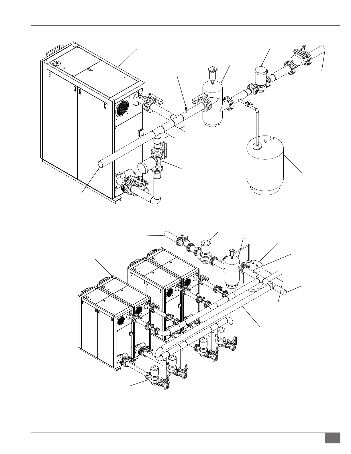
Variable Primary Piping Arrangement
Endura+ boilers are designed for installation in variable primary ow piping
arrangements (see Figures 4 and 5), sometimes referred to as full ow systems.
This arrangement eliminates temperature mixing associated with primarysecondary piping, thereby delivering the lowest temperature water directly
to the boiler return connections and increasing thermal eciency of the
condensing boiler plant.
NOTE: Although it is acceptable to install Endura+ boilers in a primary-
secondary conguration, it is not required.
Adhere to the following for variable primary piping arrangements:
Select pump(s) with sucient total dynamic head for the pressure drop of the
loop at design ow: See Figure 3 for the water side pressure drop through
the boiler. The Endura+ boiler will automatically perform a safe shutdown
Questions? Please Contact Your Local Manufacturer’s Representative
2-7
Page 14

INSTALLATION EDRP-IOM-2019-0212 SECTION 2
FULTON ENDURA+
CONDENSING BOILER
HEATING HOT
WATER RETURN
EXPANSION
TANK
AIR
REMOVAL
VARIABLE SPEED
SYSTEM PUMP
HEATING HOT
WATER SUPPLY
FULTON ENDURA+
CONDENSING BOILER
HEATING HOT
WATER RETURN
FIGURE 4 SAMPLE PIPING LAYOUT, PRIMARY ONLY VARIABLE FLOW PIPING; SINGLE BOILER
AIR
REMOVAL
RETURN WATER
TEMPERATURE SENSOR
TWO POSITION
MOTORIZED ISOLATION
VALVE
SUPPLY WATER
TEMPERATURE SENSOR
HEATING HOT
WATER SUPPLY
VARIABLE SPEED
SYSTEM PUMP
EXPANSION
TANK
FIGURE 5 SAMPLE PIPING LAYOUT, PRIMARY ONLY VARIABLE FLOW PIPING; MULTIPLE BOILERS
Note: Sample piping layout (P&ID) is a general representation of system installation. Good practice should be used in system
design, including but not limited to adequate pipe/valve sizing and natural ow path for system water.
2-8
© Fulton Group N.A., Inc. 2019
Page 15
SECTION 2 EDRP-IOM-2019-0212 INSTALLATION
HEATING HOT
WATER RETURN
FULTON ENDURA+
CONDENSING BOILER
SUPPLY WATER
TEMPERATURE SENSOR
CLOSELY SPACED TEES
( <4 x DIAMETER)
DEDICATED BOILER
(PRIMARY) PUMP
SYSTEM
(SECONDARY)
PUMP
AIR
REMOVAL
HEATING HOT
WATER SUPPLY
EXPANSION
TANK
FIGURE 6 SAMPLE PIPING LAYOUT, PRIMARY SECONDARY PIPING; SINGLE BOILER
FULTON ENDURA+
CONDENSING BOILER
HEATING HOT
WATER SUPPLY
SYSTEM (SECONDARY) PUMP
AIR REMOVAL
EXPANSION TANK
SUPPLY WATER
TEMPERATURE
SENSOR
CLOSELY SPACED TEES
( <4 x DIAMETER)
HEATING HOT
WATER RETURN
RETURN WATER
TEMPERATURE SENSOR
REVERSE RETURN
DEDICATED BOILER
(PRIMARY) PUMP
FIGURE 7 SAMPLE PIPING LAYOUT, PRIMARY SECONDARY PIPING; MULTIPLE BOILERS
Note: Sample piping layout (P&ID) is a general representation of system installation. Good practice should be used in system
design, including but not limited to adequate pipe/valve sizing and natural ow path for system water.
Questions? Please Contact Your Local Manufacturer’s Representative
2-9
Page 16

INSTALLATION EDRP-IOM-2019-0212 SECTION 2
! WARNING
All information in this manual is for
reference and guidance purposes,
and does not substitute for required
professional training, conduct,
and strict adherence to applicable
jurisdictional/professional codes and
regulations.
Do not use matches, candles, ame or
other sources of ignition to check for
gas leaks.
in the event of a low ow condition; however, proper design ow will be
required to deliver heat to users and prevent nuisance high temperature
limit trips.
Use motorized isolation valves: Ensure system eectiveness by eliminating
ow through idle boilers in accordance with ASHRAE 90.1-2013 (6.5.4.3.2).
Blending of unheated supply water may impact temperature control
operation or cause manual reset high temperature lockouts. One
motorized isolation valve should be installed per boiler; two-position type
actuator, open or closed. It is acceptable to install the valve on either the
inlet or the outlet piping of each boiler.
Motorized isolation valve control: Ensure ow paths in the hydronic loop
and residual heat in the pressure vessel is adequately dispersed when the
burner is disabled. The valve control system must be capable of leaving the
lead boiler valve open at all times.
Use a reverse return header to properly balance ow across the boilers
for multiple boiler systems: Where reverse return cannot be used, it is
recommended to install a balancing valve per boiler.
Do not install three-way mixing valves or minimum temperature protection:
The Endura+ boiler does not have a minimum return water temperature
requirement.
Primary-Secondary Piping Arrangement
It is acceptable to install the Endura+ boiler in a primary-secondary arrangement,
although this arrangement is not required. See Figures 6 and 7. Primarysecondary arrangements are used to decouple the water ow of the primary
(boiler) loop from the secondary (system) loop. Temperature mixing occurs in the
shared piping region.
Adhere to the following for primary-secondary piping arrangements:
Typical shared piping methods include closely spaced tees, a buer tank, or
a hydraulic separator.
When using closely spaced tees as a decoupling method, the tees should
be separated by four pipe diameters or less.
Install the dedicated boiler circulator on the inlet side of the Endura+
boiler, pumping into the return connection. Select pump(s) with sucient
total dynamic head for the pressure drop of the loop at design ow. See
Figure 3 for the water side pressure drop through the boiler.
For multiple boiler systems:
» Use a single common supply connection and a single common return
connection into the secondary (system) piping. Do not use separate
connections for each boiler into the secondary piping.
2-10
» Use a reverse return primary header to properly balance ow across
the boilers. Where reverse return cannot be used, it is recommended
to install a balancing valve per boiler.
© Fulton Group N.A., Inc. 2019
Page 17

SECTION 2 EDRP-IOM-2019-0212 INSTALLATION
Meet Water Chemistry Requirements
System water chemistry requirements are as follows:
pH: Range of 8.5 - 10.5
Oxygen: Less than 250 ppb (operating condition)
Total Iron/Copper: Less than 5 ppm
Corrosion Inhibitor: Capable of maintaining iron corrosion rates <2 mpy.
Due to changing environmental restrictions, a non-heavy metal ALL
ORGANIC inhibitor is recommended which is designed for multi-metal
systems including ferrous metals and yellow metals such as copper and
brass.
Chloride: Less than 200 ppm
Hardness: Less than 3.5 grains per gallon (60 ppm) in make-up/ll water.
Calcium buildup on heating surfaces is not covered under warranty.
Adhere to the following:
1. Refer to your water conditioning or chemical treatment supplier for
analysis and recommendations for proper system conditions.
2. Follow a program with appropriate monitoring and maintenance of system
water conditions as provided by your water conditioning or chemical
treatment supplier.
3. If RO/DI water is used as a source for hydronic loop water or makeup water,
it must be neutralized to a pH of 8.5 - 10.5 prior to entering the boiler.
Failure to neutralize the RO/DI water will void the pressure vessel warranty
and may cause high general corrosion rates.
The system must have an automatic pH controller to monitor and log
the levels. This must be independent of other chemical feed systems.
Makeup water pH range must be 7.5 - 8.8; the boiler water must be
maintained within pH range of 8.5 - 10.5.
4. Operate the boiler in a pressurized closed-loop system using water or
water/glycol solution. A large amount of improperly treated make-up
water can cause premature failure of the heat exchanger resulting from
scale build up. Scale build up will reduce the eciency and useful life of
the boiler and is not covered under warranty.
5. For freeze protection, an inhibited propylene glycol is recommended.
The maximum concentration is 50% glycol by volume. Only use mixtures
formulated for hydronic systems. DOWFROST™ HD is recommended. Do
not use automotive glycol.
! WARNING
All information in this manual is for
reference and guidance purposes,
and does not substitute for required
professional training, conduct,
and strict adherence to applicable
jurisdictional/professional codes and
regulations.
If the water supply must be
temporarily disconnected from the
condensate drain trap, the boilers
must be turned o to prevent
accidental ue gas emission into the
boiler room.
4 CAUTION
Some soap used for leak testing is
corrosive to certain types of metals.
Clean all piping thoroughly after
completing the leak check.
Care needs to be taken to eliminate
oxygen from the water system, as
excess oxygen in the system will
reduce the life of any boiler. The
boiler warranty does not cover heat
exchanger replacement due to oxygen
contamination of boiler water.
Heat exchanger failure due to
inappropriate water quality, foreign
matter or debris damage is not covered
under the warranty.
If the piping system attached to this
unit will be chemically cleaned, the
boiler must be disconnected from the
system and a bypass installed so that
the chemical cleaning solution does
not circulate through the boiler. If
cleaning is desired, ush the boiler with
clean domestic water only.
NOTE: For systems using up to 50% glycol, a minimum of 30 psi is required at the
boiler outlet.
6. At a minimum, the hydronic uid should be checked for glycol
concentration and pH once a year, or per glycol manufacturer schedule. A
refractometer is recommended.
Questions? Please Contact Your Local Manufacturer’s Representative
2-11
Page 18

INSTALLATION EDRP-IOM-2019-0212 SECTION 2
Prevent Oxygen Contamination
There are several ways to prevent boiler water oxygen
contamination:
Minimize system leaks to minimize make up water
requirement
Do not use open tanks or ttings
Do not use oxygen permeable materials anywhere in
the water system
Repair leaks in the system quickly
Eliminate ttings wherever possible
Use air elimination devices in system piping
Eliminate System Air
NOTE: No built-in boiler air eliminating features exist.
Adhere to the following for air elimination:
1. The installation of an air separator and air eliminator (air
vent) is required.
2. If a sealed diaphragm-type expansion tank is used,
install an air eliminator in the hot water piping at the air
separator on the suction side of the system circulator(s).
3. If an air cushion type expansion tank is used, pipe tank
directly into boiler supply on the suction side of the
system circulator(s).
4. On multi-zoned systems (or a system with both space
and domestic water heating), air elimination must be
provided either in the common piping or on every loop.
The packaged gas train (see Figure 8) is congured to operate at
specic gas pressure requirements. The standard requirements
are detailed in Table 1. Do not modify the gas train.
NOTE: Alternate or custom congurations may have
dierent requirements; always review the boiler nameplate
before installation.
The Endura+ boiler is factory test red and combustion is
adjusted per the boiler nameplate and test re report.
Inlet Gas Pressure
Adhere to the following:
Static inlet gas pressure: Measure while boiler is idle.
Verify pressure is within allowable range.
Dynamic inlet gas pressure: Measure while boiler is in
operation at maximum ring rate. Verify pressure is
within allowable range.
The gas delivery system must provide a stable and
consistent pressure across the entire turndown
range, including light o and idle conditions.
Maximum inlet gas pressure drop from static to
dynamic must not exceed 15%, or the maximum
allowable by local code (CSA B149 clause 6.3.2 for
Canada). The stricter of the two shall apply.
GAS SERVO
FLUE TRAIN INLET
NOTE: INSTALL GAS
SHUT-OFF VALVE UPSTREAM
(NOT PROVIDED)
5. When the boiler is installed at a higher level than
heating coils (e.g., a penthouse boiler room), air
elimination must be provided directly above the boiler.
Fill the Boiler with Water
To be sure that the boiler is not air-bound, open the pressurerelief valve located at the rear of the boiler. Leave the relief
valve open until a steady ow of water is observed. Close the
valve and nish lling the system.
Gas Supply Piping
The Endura+ is a gas red fully modulating boiler that
requires delivery of gas at a relatively constant pressure
and caloric content. This ensures ecient and reliable
combustion.
2-12
SHUTOFF VALVE
WITH TEST PORT
NOTE: MEASURE MAIN
GAS VALVE DOWNSTREAM
PRESSURE HERE
FIGURE 8 TYPICAL GAS TRAIN VARIES BY SIZE/MODEL
© Fulton Group N.A., Inc. 2019
SHUTOFF VALVE
WITH TEST PORT
NOTE: MEASURE INLET
GAS PRESSURE HERE
MAIN GAS VALVE
WITH HIGH AND LOW
GAS PRESSURE SWITCHES
Page 19

SECTION 2 EDRP-IOM-2019-0212 INSTALLATION
Line Gas Pressure Regulation
When inlet gas pressure exceeds the maximum on the
boiler name plate, a line gas pressure regulator is required
to step the gas pressure down to an acceptable pressure.
See Figure 9.
Proper selection and installation of a gas pressure regulator
is essential in providing ideal conditions for ecient and
reliable combustion. Adhere to the following guidelines
when selecting and installing a gas pressure regulator:
A sediment trap is recommended prior to the inlet of
the regulator.
If the level of pipe system cleanliness is unacceptable
or unknown, install a gas lter prior to the regulator.
On the outlet of the regulator: Install a straight and
uninterrupted section of pipe matching regulator
connection size with a minimum length of 10 pipe
diameters prior to any valves or ttings.
When installed in close proximity to an appliance,
some regulators may experience oscillation (hunting)
or an outlet pressure spike when demand ends.
Provide adequate volume by locating the regulator
a minimum of 10 total linear feet of pipe from boiler
fuel train inlet. Consult the regulator manufacturer for
installation requirements.
The body size should never be larger than the pipe
size. However, a properly sized regulator may be
smaller than the pipeline.
The inlet pressure used for sizing should be measured
directly at the regulator inlet. Measurements taken at
any other point may be subject to losses associated
with upstream piping.
Consult the regulator manufacturer for orice selection.
If two or more springs are available for a particular
outlet pressure in the desired range use the spring with
the lower range for better accuracy.
NOTE: Regulators are not intended for use as “shut o”
devices. As per ANSI Z21.80/CSA 6.22 lock-up is dened as an
outlet pressure not more than 150% or 5” W.C., whichever is
greater, above the setpoint after a downstream safety shuto
valve closes within 2 seconds.
Appliance regulators must not be used as line gas
pressure regulators to step down the gas pressure.
For additional information regarding gas regulator
selection and installation consult your regulator
manufacturer, any applicable local codes or ordinances,
the standard for line pressure regulators ANSI Z21.80/
CSA 6.22, and The National Fuel Gas Code NFPA 54/ANSI
Z223.1.
Gas Piping Installation
Adhere to the following for gas piping installation:
1. See Table 3 for required natural gas pipe size, based on
overall length of pipe from the meter plus equivalent
length of all ttings. Approximate sizing may be based
on 1,020 BTU for 1 cubic foot of natural gas. See Figures
6 and 7 for piping arrangements.
2. Install a manual gas shuto valve prior to the boiler.
3. Piping must be installed such that no piping stresses
are transmitted to the boiler. The boiler cannot be used
as a pipe anchor.
TABLE 3 SCH 40 PIPE NATURAL GAS CAPACITY
Nominal
Pipe Size
Inch (mm) Inch (mm) 90 Elb
1-1/4 (31.75) 1.380 (35.05) 3.45 (1.05) 6.9 (2.10) 950 ----- ----- ----- ----- ----- ----1-1/2 (38.1) 1.610 (40.89) 4.02 (1.22) 8.04 (2.45) 1460 990 810 ----- ----- ----- ----2 (50.8) 2.067 (52.50) 5.17 (1.57) 10.3 (3.13) 2750 1900 1520 1300 1150 950 800
2-1/2 (63.5) 2.469 (62.71) 6.16 (1.87) 12.3 (3.74) 4350 3000 2400 2050 1850 1500 1280
3 (76.2) 3.068 (77.92) 7.67 (2.33) 15.3 (4.66) 7700 5300 4300 3700 3250 2650 2280
4 (101.6) 4.026 (102.26) 10.10 (3.07) 20.2 (6.15) 15800 10900 8800 7500 6700 5500 4600
6 (152.4) 6.07 (154.17) 10.10 (3.07) 23.60 (7.19) ----- ----- ----- ----- 20200 16503 12766
8 (203.2) 7.98 (202.69) 13.30 (4.05) 29.10 (8.86) ----- ----- ----- ----- 41200 33660 29128
Questions? Please Contact Your Local Manufacturer’s Representative
ID Equivalent Pipe Length Max Capacity in ft3 of natural gas per hour at 14" WC pressure.
Pressure drop of 0.5" WC. Equivalent length of pipe (feet)
Feet
(meter)
Tee
Feet
(meter)
20 40 60 80 100 150 200
2-13
Page 20

INSTALLATION EDRP-IOM-2019-0212 SECTION 2
4. The boiler and all gas piping connections must be
pressure-tested and checked for leaks before being
placed into service. Test with compressed air or inert
gas if possible.
5. The boiler must be disconnected at the boiler manual
shuto valve (located at the end of the supplied gas
train) from the gas supply piping system during any
pressure testing of the system at pressures in excess of
2.0 psig (55 inch W.C.).
6. Gas Piping must be installed in accordance with
National Fuel Gas Code, ANSI Z223.1 1991 or latest
addenda and any other local codes, which may apply.
7. The pipe and the ttings used must be new and free of
dirt or other deposits.
8. Piping must be of the proper size to ensure adequate
gas supply. A drip leg and union connection must be
installed upstream of the gas safety shut o valves and
must be a 5 inch (127 mm) minimum length.
GAS SHUTOFF VALVE
(NOT PROVIDED)
MINIMUM 10 LINEAR FEET OF
PIPE BETWEEN REGULATOR
9. Connect gas supply line to the open end of the tee on
which the drip leg is installed.
10. When making gas-piping joints, use a sealing
compound resistant to liqueed petroleum gases. Do
not use Teon tape on gas line threads.
11. After gas piping is completed and before wiring
installation is started, carefully check all piping
connections (factory and eld) for gas leaks. Use a soap
and water solution or combustible gas detector. A GASMate® 0119 or equivalent is recommended.
12. The boiler must be disconnected at the boiler shut o
valve from the gas.
LINE GAS PRESSURE REGULATOR
AND BOILER
NOTE: REQUIRED FOR INSTALLATIONS
WHERE SUPPLY GAS PRESSURE EXCEEDS
MAXIMUM ON BOILER NAME PLATE.
(NOT PROVIDED)
GAS SHUTOFF VALVE
(NOT PROVIDED)
GAS SUPPLY
2-14
FIGURE 9 ENDURA+ SINGLE BOILER GAS SUPPLY PIPING
© Fulton Group N.A., Inc. 2019
Page 21

SECTION 2 EDRP-IOM-2019-0212 INSTALLATION
LINE GAS PRESSURE REGULATOR
` MULTIPLE BOILER INSTALLATION
When gas supply pressure exceeds the maximum on the
boiler name plate, a line gas pressure regulator is required. It
is recommended that an individual regulator be used at each
boiler. See Figure 10.
When a single regulator is used for multiple boilers, the
regulator must be appropriate for the entire gas delivery ow
(CFH) turndown range. This includes all boilers on at full re to
one boiler on at low re.
GAS SHUTOFF VALVE
(NOT PROVIDED)
MINIMUM 10 LINEAR FEET OF
PIPE BETWEEN REGULATOR
AND BOILER
NOTE: REQUIRED FOR INSTALLATIONS
WHERE SUPPLY GAS PRESSURE EXCEEDS
MAXIMUM ON BOILER NAME PLATE.
(NOT PROVIDED)
GAS SHUTOFF VALVE
(NOT PROVIDED)
GAS SUPPLY
FIGURE 10 ENDURA+ MULTIPLE BOILER GAS SUPPLY PIPING
Questions? Please Contact Your Local Manufacturer’s Representative
2-15
Page 22

INSTALLATION EDRP-IOM-2019-0212 SECTION 2
Components Requiring Ventilation to the
Outdoors
NOTE: The port marked “AIR” on the SKP25 actuator cannot
be used as as gas vent connection. Connecting a vent line to
this port may cause operational issues.
The following do not require ventilation to the outdoors, as
there is a vent limiter in use:
Regulator on the pilot line (not applicable to all sizes).
An authority having jurisdiction (AHJ) may not permit the
use of a vent limiter on some or all components. If venting is
required, use the following general guidelines:
Drill an appropriately sized penetration for each vent
line of the boiler cabinet. Do not install any vent lines
through removable latching panels. Properly seal
around the pipe with sensor safe silicone.
Each component must have a separate vent line to
the outdoors. Vent lines must not be manifolded or
combined with any other vent or exhaust systems.
Start with the vent connection size and as soon as it is
practical, increase the pipe size one diameter. For every
ten feet of vent, increase the pipe size one diameter.
Never reduce the vent size.
Protect the vent termination from debris, dust and
insects. Install the vent termination above the snow
line and point down to prevent ingress of water. The
termination must be a minium of 3 ft (0.9 m) from a
source of ignition.
Install Condensate Drain Trap
A condensate drain trap is intended for use with the Fulton
Endura+ boiler.
Single Boiler Drain Trap
The single boiler condensate drain trap is Fulton Part Number
4-57-005500. The drain trap must be congured one per
boiler, with a maximum of 4.0 MMBH total. (See Figures 11
and 13).
Adhere to the following for installation:
1. A exible condensate drain hose must be installed
between the boiler and any piping anchored to the
oor. Ensure that there are no low spots.
2. The 1 inch (25.4 mm) boiler condensate drain outlet will
be reduced and connected to the 3/4 inch (19.05 mm)
inlet on the top of the drain trap.
3. A condensate collecting tank and condensate pump
will be required if a oor drain is not available to collect
condensate (collecting tank and pump are not supplied
with the boiler).
4. All piping (Figure 11) must be CPVC, high temperature
silicone tubing, galvanized, or stainless steel, and be
free of leaks. Copper, carbon steel/iron pipe, or PVC are
not acceptable.
5. The 3/4 inch (19.05 mm) drain trap outlet must remain
below the 1 inch (25.4 mm) boiler condensate drain.
6. Connect the 3/4 inch (19.05 mm) trap outlet to an
appropriate waste line following applicable codes. The
3/4 inch (19.05 mm) drain connection on the drain tank
must be the highest point prior to going to the drain.
Failure to keep drain piping lower than this point will
result in overow of the drain tank. Slope the drain pipe
away at a minimum pitch of 1 inch (25.4 mm) for every
12 feet (3.65 m).
2-16
7. Ensure condensate drain piping will not be exposed to
freezing temperatures.
© Fulton Group N.A., Inc. 2019
Page 23

SECTION 2 EDRP-IOM-2019-0212 INSTALLATION
(NOT PROVIDED)
Figure Notes:
1. Pipe must be level or slightly pitched toward the drain.
2. Pipe material must be CPVC, high-temperature silicone
tubing, galvanized steel, or stainless steel.
3. The condensate drain trap outlet must be below the
condensate outlet of the boiler.
4. The maximum capacity to attach per condensate drain
kit is 4 MMBH total.
SIDE VIEW
HOUSEKEEPING PAD
MINIMUM 4-INCH (102 MM)
FLEXIBLE DRAIN HOSE
(SUPPLIED, REQUIRED)
REDUCING BUSHING
BACK VIEW
FIGURE 11 CONDENSATE DRAIN PIPING FOR INDIVIDUAL ENDURA+ BOILER
Questions? Please Contact Your Local Manufacturer’s Representative
2-17
Page 24

INSTALLATION EDRP-IOM-2019-0212 SECTION 2
BACK VIEW
HOUSEKEEPING PAD
MINIMUM 4-INCH (102 MM)
FLEXIBLE, DRAIN HOSE
(SUPPLIED, REQUIRED)
Figure Notes:
1. Header must be level or slightly pitched toward the
drain.
2. Header material must be CPVC, high-temperature
silicone tubing, galvanized steel, or stainless steel.
3. Header should be taken to the lowest point
possible and maintain a minimum 2-inch (51 mm)
drop from the boiler condensate drain outlet.
4. The condensate drain trap outlet must be below
the condensate outlet of the boiler.
5. For multiple boiler installation, maintain minimum
pipe size of one inch (25.4 mm) for the header
piping.
Note: A ¼" fresh water
makeup line is required.
HEADER MUST BE AT
FLOOR (NOT PAD) HEIGHT
¼" TAPPING PROVIDED
FOR FRESH WATER
CONNECTION
≥2"
SIDE VIEW
6. The maximum capacity to attach per multiple
boiler condensate drain trap is 12 MMBH total.
FIGURE 12 CONDENSATE DRAIN PIPING FOR MULTIPLE ENDURA+ BOILERS
2-18
© Fulton Group N.A., Inc. 2019
Page 25

SECTION 2 EDRP-IOM-2019-0212 INSTALLATION
RIGHT SIDE VIEW
1 1/2
1 3/8
7 3/4
10 11/16
10 1/8
6 1/2
7 5/8
FRONT VIEWTOP VIEW
(COVER NOT SHOWN)
5/8
3/8" (TYP.)
1/4" WATER SUPPLY
CONNECTION
6 1/2
5 1/8
Multiple Boilers Sharing A Common Drain Trap
The multiple boiler condensate drain trap is Fulton Part Number
4-57-000440. The maximum capacity to attach per condensate
drain trap is 12 MMBH total. (See Figures 12 and 14).
Adhere to the following for installation:
1. A exible condensate drain hose must be installed
between the boiler and any piping anchored to the oor.
Ensure there are no low spots.
2. The Fulton Endura+ boiler 1 inch (25.4 mm) condensate
drain outlet will be connected to the 1 inch (25.4 mm)
inlet on the drain trap. One or more drain lines may be
connected to this inlet (max of 12 MM BTU per drain)
using a common header pipe.
3. If the water supply must be temporarily disconnected,
the boilers must be turned o to prevent accidental ue
gas emission into the boiler room.
4. The condensate drain cover must be kept on at all times,
except during maintenance of the drain. This drain
should be checked regularly in your boiler maintenance
schedule.
5. A condensate collecting tank and condensate pump
will be required if a oor drain is not available to collect
condensate (collecting tank and pump are not supplied
with the boiler.)
6. All piping (Figure 12) must be CPVC, high-temperature
silicone tubing, galvanized, or stainless steel, and be
free of leaks. Copper, carbon steel/iron pipe or PVC are
not acceptable.
7. Connect 1 inch (25.4 mm) condensate drain(s) (at the
rear of the boiler), to the 1 inch (25.4 mm) inlet at the
base of the drain tank. The header must be at least 5.5
inches (14.2 cm) below the condensate outlet of the
individual boiler, and must remain ooded - achieved
by ensuring it is at least 5.5 inches (14.2 cm) below the
outlet of the condensate drain trap.
8. Connect the 1.5 inch (38.1 mm) drain outlet to an
appropriate waste line following applicable codes. The
1.5 inch (38.1 mm) drain connection on the drain tank
must be the highest point prior to going to the drain.
Failure to keep drain piping lower than this point will
result in overow of the drain tank. Slope the drain pipe
away at a minimum pitch of 1 inch (25.4 mm) for every
12 feet (3.65 m).
9. Attach a ¼” water supply to the compression tting
on the oat. The water line must be connected to
an uninterruptible supply. Install before the “fast ll”
valve to the boiler supply—but after the back ow
preventer—to avoid contamination of a potable water
supply. Maximum allowable water pressure to the
compression tting is 100 PSI (689.5 kPa).
10. Ensure condensate drain piping will not be exposed to
freezing temperatures.
3/4" NPT
FRONT VIEW BACK VIEW TOP VIEW
FIGURE 13 SINGLE BOILER CONDENSATE DRAIN TRAP
Questions? Please Contact Your Local Manufacturer’s Representative
FIGURE 14 MULTIPLE BOILER CONDENSATE DRAIN TRAP
4 13/16
3/4" NPT
11/16
2-19
Page 26

INSTALLATION EDRP-IOM-2019-0212 SECTION 2
TOP VIEW
TANK COVER REMOVED FOR CLARITY
2
3
E
D
C
E
D
C
E
D
C
B
F
ISOMETRIC VI EW
FRONT VI EW
TOP VIEW
E
D
C
B
F
A
ISOMETRIC VI EW
FRONT VI EW
TOP VIEW
E
D
C
B
F
A
E
D
C
B
F
ISOMETRIC VIEW
LEFT VIEW
MULTIPLE BOILER
ASSEMBLY
6
½"
1
3"
1½" N.P. T.
OUTLET
12½"
11⅜"
1½" N.P.T.
6½"
INLET
2¾"
FRONT VIEW
RIGHT VIEW
2¾"
FIGURE 15 FULTON PH NEUTRALIZING KIT
SINGLE BOILER
ASSEMBLY
2-20
E
D
C
F
B
ISOMETRIC VI EW
A
F
C
B
Multiple Boilers Individual Boiler
(A) pH Kit Outlet 1 1/2” 1 1/2”
(B) Condensate Drain Trap 4-57-000440 4-57-005500
(C) Drain Outlet 1 1/2” 3/4”
(D) pH Kit Inlet 1 1/2” 1 1/2”
(E) pH Neutralization Kit 4-50-000008 4-50-000008
(F) Drain Inlet 1” 3/4”
Neutralizing Media 2-30-001580 2-30-001580
FIGURE 16 FIELD CONNECTIONS FOR CONDENSATE DRAIN TO PH NEUTRALIZATION TANK
E
D
ISOMETRIC VI EW
A
© Fulton Group N.A., Inc. 2019
Page 27

SECTION 2 EDRP-IOM-2019-0212 INSTALLATION
! WARNING
Install pH Neutralization Kit
The pH Neutralization Kit uses a consumable medium to bring the pH level of the
boiler’s condensate to a more neutral level. It is not a replacement or alternative
for the Condensate Drain Trap. See Figures 15 and 16.
Adhere to the following for pH Kit installation:
1. Use CPVC, high-temperature silicone tubing, stainless, or galvanized pipe
and ttings to connect condensate trap to kit.
2. Connect kit downstream of Condensate Drain Trap. See Figure 16.
3. Pipe outlet to appropriate drain. It is acceptable to use PVC or CPVC on the
outlet to drain.
4. Check condensate pH periodically.
NOTE: Replacement bags are available from your Fulton local representative.
The medium in the container will neutralize the condensate of 12 MMBH for
approximately 6 months. (Fulton Part No. 2-30-001580)
All information in this manual is for
reference and guidance purposes,
and does not substitute for required
professional training, conduct, and strict
adherence to applicable jurisdictional/
professional codes and regulations.
4 CAUTION
An uninterruptible water supply is required
for the multiple boiler condensate trap
and shall be connected to the ¼” (U.S.
only) compression tting. The water supply
maintains a water level in the drain kit to
prevent accidental ue gas emission into the
boiler room.
Venting Requirements
Adhere to the following venting requirements:
1. The Endura+ boiler can operate to the combined intake and ue exhaust
pressure drops without altering standard capacities: See Table 4.
2. The venting system draft pressure readings at the boiler exhaust
connection and air intake connection cannot exceed the maximum
values stated in Table 4; and must remain relatively stable throughout all
operating conditions, including the ignition sequence.
NOTE: Venting pressure is the combined result of frictional pressure drop and
natural draft (stack eect) in the combustion air intake piping (if used) and ue
gas exhaust system.
3. Drastic draft changes during operation may result in the generation of
excessive carbon monoxide or soot, which may aect operational reliability
and condition of burner, ignition assembly, or other combustion system
components leading to increased maintenance or replacement of these
items.
4. The equivalent length method is not an approved engineering method
for determining acceptability of a vent system due to varying burner
modulation rates, ambient air temperatures, and ue gas temperatures,
among other factors. Combustion air intake piping (if used) must be
accounted for in an analysis of the venting system.
5. If the maximum positive pressure is exceeded, the boiler may have to be
de-rated or require the installation of draft accessories such as a properly
selected exhaust assist fan to prevent operational issues from occurring. If
the maximum negative pressure is exceeded due to excessive natural draft
(stack eect), the exhaust system may require the use of draft accessories
such as a xed-position balancing bae or modulating overdraft damper.
Questions? Please Contact Your Local Manufacturer’s Representative
2-21
Page 28

INSTALLATION EDRP-IOM-2019-0212 SECTION 2
! WARNING
Do not terminate venting into an
enclosed area.
Never use open ame or smoke from
a cigarette, cigar, or pipe as a testing
method during boiler installation,
operation, or maintenance.
Foreign substances, such as
combustible volatiles in the
combustion system can create
hazardous conditions. If foreign
substances can enter the air stream,
the boiler combustion air inlet must
be piped to an outside location.
Draft accessories must be appropriate for Category II/IV installations
and are not included with the boiler. Consult your venting supplier for
recommendations.
6. Adhere to local and jurisdictional codes and regulations, which may dier
from recommendations and diagrams contained in this manual.
7. Site specic conditions not addressed in this manual may require
additional precautions or design considerations. Consult your local Fulton
Representative and venting supplier for recommendations.
NOTE: Consult your venting pipe supplier for assistance with sizing of vent
materials and other potentially required accessories.
8. The layout of the piping used for air intake and exhaust must be done in a
way that facilitates smooth travel and natural ow.
9. A pressure drop calculation is an acceptable method for evaluating
theoretical draft, but is not enough information to fully validate
combustion air intake and ue gas exhaust vent systems. The designer and
installer must use good practice and remain cognizant of important factors
that cannot be captured by a pressure drop calculation such as local code
requirements, accessibility for inspection and maintenance, aesthetic
concerns, ue gas recirculation, stagnant vapor plumes, prevailing wind
direction, nearby mechanical equipment and other design considerations
as detailed in this manual. Some recommendations:
Avoid sharp turns, boot tees, bullhead tees, back-to-back 90
degree elbows, short radius elbows.
Avoid extensive direction changes (ue gases being required
to turn around).
Never direct ue stacks in a downward direction.
TABLE 4 GENERAL VENTING PRESSURE REQUIREMENTS
Endura+ Model
Number
EDR+2500 -0.10” W.C. +1.50 “ W.C.
EDR+3000 -0.10” W.C. +1.50 “ W.C.
EDR+4000 -0.10” W.C. +1.00 “ W.C.
EDR+5000 -0.10” W.C. +1.00 “ W.C.
EDR+6000 -0.10“W.C. +1.00 “ W.C.
Maximum
Negative Draft
Maximum
Positive Draft
Combustion Air Intake
Adhere to the following for installation:
1. It is the responsibility of the designer and installer of the venting system to
guarantee the prevention of ue gas recirculation (ue gases being drawn
into a boiler’s combustion air supply, or ue gases moving backward
through an idle boiler).
2-22
2. The installation of room exhaust fans in a boiler room is not recommended.
A boiler room exhaust fan or similar equipment can create down draft
in the stack or restrict the burner’s air supply which will result in poor
combustion.
© Fulton Group N.A., Inc. 2019
Page 29

SECTION 2 EDRP-IOM-2019-0212 INSTALLATION
! WARNING
3. It is essential that only fresh air is allowed to enter the combustion
air system. Foreign substances, such as combustible volatiles in the
combustion system can create hazardous conditions.
4. Particulate matter or chemicals (example: chlorine, sulfur, freon, uorine,
perchlorethylene, halogenated compounds) in the combustion air supply
to the boiler will cause damage or failure to the heat exchanger and/
or burner and is not covered under warranty. High-risk situations for
particulate matter to be in the air include construction and maintenance
activities. See Table 5.
All information in this manual is for
reference and guidance purposes,
and does not substitute for required
professional training, conduct, and strict
adherence to applicable jurisdictional/
professional codes and regulations.
4 CAUTION
NOTE: Pool and laundry room air may be contaminated with chlorine or uorine
compounds. If allowed to enter the combustion air supply, these contaminants
will signicantly increase the acidity of ue gas condensate, potentialy damaging
heat transfer surfaces. Damage to the heat exchanger due to poor combustion air
quality is not covered under warranty.
TABLE 5 PRODUCTS/CONTAMINANTS TO AVOID
Products to
avoid
Areas with
the potential
to have
contaminants
Products containing chloro/ourocarbons; chlorinebased products; calcium chloride products, sodium
chloride products, paint and varnish removers,
hydrochloric acid, muriatic acid, cements, glues, antistatic
fabric softeners, Freon, drywall particles, dirt, berglass.
Dry cleaning/laundry areas; swimming pools; repair
shops; processing plants; manufacturing plants, active
construction sites; chemical storage; food processing
plants; farms; chillers; cooling towers.
Combustion Air Supply From the Boiler Room
Adhere to the following for installation:
1. Adequate combustion air and ventilation must be supplied to the boiler
room in accordance with local codes and NFPA54/ANSI Z233.1, Section
9.3, Air for Combustion and Ventilation or CSA-B149.1 for Canada. The
minimum net free area requirements in Table 6 may not supersede
local and jurisdictional codes and regulations where there codes and
regulations require an opening of greater net free area. The boiler room
must meet the NFPA criteria for a non-conned space.
Oxygen sensors are susceptible to silicone
poisoning, which can cause premature
degradation. Use only "sensor safe" silicone
around the boiler and on combustion air
supply materials.
2. Verify combustion air is taken from the outdoors and not from the
inhabited or occupied spaces within the building. Ensure space and
nearby products are evaluated for the potential of combustion air
contaminants. See Table 5.
3. For installations providing two permanent openings directly
communicating with the outdoors, the minimum net free area of each
opening is 1 in per 4,000 BTU/hr of the total input capacity of the
combined burners located in the boiler room. A high opening and a low
opening is required. Ensure the high opening commences within 12 inches
of the ceiling, and the low opening commences within 12 inches of the
oor. See Table 6.
Questions? Please Contact Your Local Manufacturer’s Representative
2-23
Page 30

INSTALLATION EDRP-IOM-2019-0212 SECTION 2
! WARNING
All information in this manual is for
reference and guidance purposes,
and does not substitute for required
professional training, conduct, and strict
adherence to applicable jurisdictional/
professional codes and regulations.
4 CAUTION
Do not use insulation on polypropylene
materials. Use of insulation may elevate pipe
wall temperatures, resulting in the potential
for vent material failure.
Ensure there is not negative pressure in the
boiler room. The boiler room pressure must
be neutral relative to the outdoors.
4. For installations providing a single permanent opening directly
communicating with the outdoors, the minimum net free area of each
opening is 1 in per 3,000 BTU/hr of the total input capacity of the
combined burners located in the boiler room. See Table 6.
TABLE 6 MAKEUP AIR VENTILATION OPENINGS
Boiler Input
Capacity
(MBTU/HR)
2500 4.4 4.4 5.8
3000 5.2 5.2 7.0
4000 6.9 6.9 9.3
5000 8.8 8.8 11.6
6000 10.4 10.4 14.0
5. For multiple boiler installations, multiply the number of boilers by required
net free area per boiler.
6. The net free area required for the boiler(s) is in addition to the combustion
or ventilation air supply requirements of other equipment sharing the
same space such as water heaters, generators, air compressors, or other
boilers. The boiler room must have an opening or openings not less than
the total net free area required for all types of equipment.
Two Openings - Min. Net
Free Area Each (SQFT)
Low High
Single Opening Only
Min. Net Free Area
(SQFT)
7. Consider the blocking eects of louvers, grills, and screens on the net free
area of each opening. Ensure ventilation openings are unobstructed.
8. Ensure there is not negative pressure in the boiler room. The boiler room
pressure must be neutral relative to the outdoors.
9. Where mechanical combustion air supply systems are used, such as a
combustion air supply fan or a motorized louver, they must be interlocked
with the boiler control panel to prove operation prior to burner ignition
and during burner operation. Where manual louvers are used, ensure they
are fully open prior to operating the boiler(s).
Air Piped From Outside Boiler Room
The combustion air supply can be piped directly to the air inlet of the boiler.
Adhere to the following for installation:
1. An adapter kit (factory option) is required to connect the boiler air inlet to
the combustion air piping. Use a rubber coupling to connect the air inlet
adapter to the air intake piping.
NOTE: The weight of combustion air intake piping must not be supported by the
boiler. Ensure air intake piping is externally supported on hangers or straps.
2. The air intake must be piped out of the building if the boiler room contains
contaminated air.
2-24
3. The combustion air intake termination must be located as to not be
subjected to the intake/exhaust of other mechanical equipment such as
other fuel red heating equipment, loading docks, generators, air handling
systems, and cooling towers.
© Fulton Group N.A., Inc. 2019
Page 31

SECTION 2 EDRP-IOM-2019-0212 INSTALLATION
4. Ensure the boiler room air is maintained at a dew point temperature below
the temperature of combustion air. Failure to provide adequate ventilation or
control dew point temperature may increase maintenance or damage boiler
components.
5. The air intake system must be designed to prevent any moisture from
draining to the boiler. Slope the air intake duct down away from the boiler.
See Figures 18 and 20.
6. Air Intake pipes and ttings shall be Schedule 40 PVC pipe or smoothwalled galvanized steel. All Schedule 40 PVC pipe, ttings, primer and
cement must conform to American National Standard Institute and the
American Society for Testing and Materials (ANSI/ASTM standards) per pipe
manufacturer’s requirements.
7. Intake PVC piping must be assembled using cement. This will ensure that
the intake is air tight and will not allow contaminates from the boiler room
into the boiler. The cement must be free owing and contain no lumps,
undissolved particles or any foreign matter that adversely aects the joint
strength or chemical resistance of the cement. The cement must not show
gelation, stratication, or separation that cannot be removed by stirring.
8. Adhere to procedure for cementing joints (per ASTM D2855).
9. Avoid sidewall exhaust with roof-terminated intake air. This may lead to
reverse stack eect when the boiler is idle.
! WARNING
Fulton accepts no liability for installation
of any venting, including the selection of
venting materials. Maximum allowable
ue gas operating temperatures may
vary by manufacturer. Consult the
venting supplier for maximum allowable
temperatures.
Barometric dampers must never be used in
a positive pressure exhaust or direct vent
sealed combustion application.
Air Filter
The air lter requires monthly inspection and, at minimum, annual replacement.
See Maintenance section of this manual.
Flue Gas Exhaust Venting
The Endura+ is equipped with a vent connection at the lower rear of the boiler.
Adhere to National Fuel Gas Code (ANSI Z223.1) and the following for installation:
1. The Endura+ is a Category II/IV appliance, thus venting material must be
appropriate for condensing, positive pressure applications. Any venting
material supplied for the Endura+ boiler must be AL29-4C or 316L SS, listed
and labeled to UL 1738, and guaranteed appropriate for the application by
the manufacturer and supplier of the venting. It is also acceptable to vent
the Endura+ as a Category II condensing, negative pressure, for which an
upsized diameter is typically required.
2. Do not use boot tees or bullhead tees. Use inline condensate drains in
place of boot tees at the bottom of a vertical rise.
3. Barometric dampers are physically open to the mechanical space.
When used in a condensing boiler application with negative pressure
(Category II) exhaust vent, the design must prevent ue gas condensate
from draining down the outside of the stack or dripping into the space.
Barometric dampers must never be used in a positive pressure exhaust or a
direct vent sealed combustion application.
4. Where allowed by the authority having jurisdiction (AHJ), the exhaust may
be vented using polypropylene listed and labeled to UL 1738 or ULC S636.
Do not insulate polypropylene exhaust vents.
5. Refer to Table 7 for acceptable vent materials and temperature limits.
Questions? Please Contact Your Local Manufacturer’s Representative
2-25
Page 32

INSTALLATION EDRP-IOM-2019-0212 SECTION 2
FIGURE 17 TYPICAL COMMON EXHAUST LAYOUT
SEE NOTES 4, 5, 6
FULTON ENDURA+
CONDENSING BOILER
SEE NOTE 7
SEE NOTE 8
SEE NOTE 8
REAR VIEW
Figure 17 Notes:
1. All installations must be in compliance with local and
national codes. This is a typical arrangement for reference
purposes only. Actual installations may require alternate
or additional components which are not shown for clarity.
2. This drawing is not for construction purposes.
3. Adhere to clearance and installation requirements.
4. The common exhaust header should be maintained at a
slight negative pressure within the requirements of the
boiler. A positive pressure common header will require
draft accessories to guarantee ue gases cannot travel
backward through an idle boiler.
5. A constant diameter common header is recommended.
Do not use the static regain method.
6. A minimum 1/4” rise per foot run is required.
7. A 45° reducing tee or elbow in the direction of ow is
recommended. Straight or 90° tees must not be used.
2-26
8. Do not use boot tees or bull head tees.
ISOMETRIC VIEW
9. Endura+ boilers cannot be common vented with other
equipment.
© Fulton Group N.A., Inc. 2019
Page 33

SECTION 2 EDRP-IOM-2019-0212 INSTALLATION
The use of PVC/CPVC or Radel® (polyphenylsulfone) in venting systems is
prohibited.
6. A stainless steel adapter (not supplied) specic to vent manufacturer type
and material will be required. Consult the venting supplier for guidance.
7. Adequate provision must be made to support the weight of the exhaust
venting. It cannot be supported by the boiler exhaust connection.
8. Follow the venting manufacturer’s instructions for installation of exhaust
venting.
9. Horizontal vents must allow for ue gas condensate to drain back to the
boiler exhaust connection with a minimum pitch of ¼” (7 mm) per foot
(300 mm) run. Failure to do so can create a condensate pocket, which can
result in an inoperative boiler. There must be no low spots in the exhaust
vent, as this can also result in a condensate pocket. A high spot acceptable,
provided the minimum pitch is maintained in both directions.
10. The boiler control will automatically disable and reset the burner should
the ue gas temperature exceed the stack limit setting. The factory default
stack limit may be eld adjusted (See Operation) for installations utilizing
a material in Table 7 approved for higher ue gas temperatures.
! WARNING
All information in this manual is for
reference and guidance purposes,
and does not substitute for required
professional training, conduct, and strict
adherence to applicable jurisdictional/
professional codes and regulations.
11. If stack drains are installed, they must be properly pitched and combined
with the boiler ue gas condensate drain piping into the condensate drain
trap.
TABLE 7 ACCEPTABLE EXHAUST VENTING MATERIALS
Venting
Material
Maximum
Flue Gas
Temperature
AL29-4C
(UL1738)
600° F
(315° C)
316L SS
(UL1738)
550° F
(287° C)
Polypropylene
(UL 1738)
230° F
(110° C)
TABLE 8 FULTON APPROVED FLUE GAS VENTING ADAPTERS*
Manufacturer Line Material Part/Catalog Number
EDR+2500/3000 EDR+6000
M&G DuraVent® FasNSeal® AL29-4C
Schebler eVent™ AL29-4C Consult Vendor Consult Vendor
Selkirk® Heat-
Fab®
Saf-T Vent® AL29-4C 96EDRPLUS Consult Vendor
810013180
(2-35-001655)
810013438
(2-35-001654)
Jeremias® GOV 444 SS SWKL8FBA-ENDPLUS Consult Vendor
*Note: This table lists factory approved ue gas venting adapters; other manufacturers
may be used provided they meet the special gas vent requirements of this boiler.
Questions? Please Contact Your Local Manufacturer’s Representative
2-27
Page 34

INSTALLATION EDRP-IOM-2019-0212 SECTION 2
Common Venting Layouts for Endura+
It is possible to combine the air intake and/or exhaust venting
of multiple Endura+ boilers. The pressure drop across the
entire common system, the combined total of both air
intake and exhaust, must comply with the draft pressure
requirements for an individual boiler, see Table 4.
Refer to Figure 17 and adhere to the following for installation:
1. Consult your venting supplier for guidance in designing
common vented installations. The system must be
designed to prevent backow of exhaust gases through
idle boilers.
2. Endura+ boilers are not approved for combined
venting with other equipment such as steam boilers,
water heaters, generators, and other types of Fulton
equipment.
3. A constant diameter common header is recommended.
Do not use the static regain method.
4. A minimum 1/4” rise per foot run is required for
horizontal sections.
5. Where individual stacks transition into the common
header, a 45 degree reducing tee or elbow in the
direction of ow is recommended. Straight-in or 90
degree tees must not be used.
When designing a draft system for a quantity of two or more
Endura+ boilers, the following items must be considered
and addressed by the parties responsible for designing and
providing that system:
3. Precautions must be taken to ensure that the draft
pressure at each boiler is maintained within in the
required range (refer to Table 4) throughout all
conditions while also maintaining a slight negative
draft pressure in the common exhaust header. Consider
all possible operating conditions of the exhaust system
specic to the application, including:
Low and high ue gas temperatures
Low and high ambient air temperatures
All boilers operating at their maximum input
rating capacity
One boiler in the system operating at the low re
position
No boilers on, pre-purge and ignition
4. Consider the natural draft eects associated with
vertical exhaust vent rise. Over-draft control accessories,
such as modulating stainless steel dampers, may be
required to mitigate a negative pressure exceeding the
value in Table 4. An undersized common exhaust vent
or pressure drop due to horizontal run can create a
positive pressure common exhaust situation which may
require a mechanical draft assist (exhaust fan) system.
5. If the common exhaust conguration does not allow
for a stable negative pressure under all operating
conditions then a mechanical draft assist system, such
as a variable speed exhaust fan, may be required.
Venting Terminations
` COMMON VENTING EXHAUST BACKFLOW PREVENTION
1. When combining the exhaust vents of multiple
Endura+ boilers, the system must be designed to
guarantee ue gas and exhaust will not backow
through an idle boiler. This requires appropriately sizing
the common exhaust vent to maintain a slight negative
draft pressure throughout all operating conditions.
Alternative solutions may be considered provided
the solutions to prevent ue gas recirculation (FGR),
exhaust backow, and unacceptable draft pressures
have been thoroughly evaluated by the venting
designer and supplier.
2. It is recommended to install individually piped intake
vents or use neutral pressure boiler room air with a
common exhaust system. For common exhaust vent
applications also combining combustion air intake (CAI)
vents into a common pipe, it is necessary to size the
common CAI pipe for a negligible pressure loss.
2-28
Adhere to the National Fuel Gas Code (ANSI Z223.1) and the
following for installation:
1. Do not terminate the venting in an enclosed area. Care
must be taken when selecting the orientation of the
terminations.
2. All vent pipes and ttings must be installed with
appropriate air space clearances to combustibles. These
air space clearances apply to indoor or outdoor vents—
whether they are open, enclosed, horizontal or vertical
or pass through oors, walls, roofs, or framed spaces
(See Figures 18, 19 and 20). The air space clearances
should be observed to joists, studs, sub oors, plywood,
drywall or plaster enclosures, insulating sheathing,
rafters, roong, and any other material classed as
combustible.
© Fulton Group N.A., Inc. 2019
Page 35

SECTION 2 EDRP-IOM-2019-0212 INSTALLATION
NOTES:
1) HORIZONTAL SECTIONS MUST ADHERE TO A MINIMUM
1/4 INCH PER FOOT (1 MM PER 48 MM) RISE TO RUN RATIO
2) MAINTAIN A MINIMUM 9 INCH (229 MM) AIR SPACE
CLEARANCE TO COMBUSTABLES, WIRE, AND INSULATION
3) INSTALL SUPPORT STRAPS AT 5 FT (152 CM) HORIZONTAL
INTERVALS AND AT ELBOWS
ENDURA+
HYDRONIC
BOILER
( SIDE VIEW )
TYPICAL ROOF PENETRATIONS
COMBUSTION AIR FROM THE OUTDOORS
( SUGGESTED INSTALLATION CONFIGURATIONS )
MIN 4 FT
(122 CM)
ADJUSTABLE
FLASHING
METAL PLATE
FIRE STOP
ADJUSTABLE
FLASHING
ADHESIVE SEAL
STORM COLLAR
COMBUSTION
AIR INLET 90° ELBOW
1/2 INCH x 1/2 INCH
(13 MM x 13 MM)
MESH SCREEN
FLUE GAS EXHAUST TERMINATION
(RAIN CAP NOT REQUIRED)
IF SNOW ACCUMULATION
IS APPLICABLE, OPENING TO BE
MIN 1 FT (30 CM ) ABOVE
THIS NORMALLY EXPECTED LEVEL.
DO NOT PLACE INSULATION IN
REQUIRED AIR SPACE CLEARANCE
SCH40 PVC PIPE (TYPICAL)
REFERENCE TABLE 1 FOR MIN CAI DIAMETER
STORM COLLAR
FLEXIBILE RUBBER
PIPE COUPLING
FLUE GAS EXHAUST
DIRECTION OF FLOW
COMBUSTION AIR INLET (CAI)
DIRECTION OF FLOW
STORM COLLAR
(FOR DOUBLE WALL)
AIR INTAKE ADAPTER
(STYLE & LOCATION VARIES)
MIN 4 FT (122 CM)
ABOVE AIR
INTAKE PIPING
UL-1738 APPROVED
EXHAUST VENT MATERIAL
LEVEL HOUSEKEEPING PAD
MIN 4 INCH (102 CM) HEIGHT
FLEXIBLE HOSE
CONDENSATE TRAP (STYLE VARIES)
IN LINE STACK DRAIN
(RECOMMENDED FOR HIGH CONDENSATE
PRODUCTION RATE APPLICATION)
APPLIANCE ADAPTER
CONSULT FLUE MFG FOR SELECTION
REFERENCE TABLE 1 FOR FLUE GAS STACK DIAMETER
CAUTION:
SEPARATE AIR INTAKE AND EXHAUST TERMINATIONS AS FAR AS
POSSIBLE TO PREVENT FLUE GAS RECIRCULATION (FGR) DURING
DIFFERENT WIND CONDITIONS.
EXHAUST STACK IS DOWNWIND
OF AIR INTAKE OPENING
FIGURE 18 ROOF PENETRATION DETAILS
Questions? Please Contact Your Local Manufacturer’s Representative
2-29
Page 36

INSTALLATION EDRP-IOM-2019-0212 SECTION 2
NOTES:
1) HORIZONTAL SECTIONS MUST ADHERE TO A MINIMUM
1/4 INCH PER FOOT (1 MM PER 48 MM) RISE TO RUN RATIO
2) MAINTAIN A MINIMUM 9 INCH (229 MM) AIR SPACE
CLEARANCE TO COMBUSTABLES, WIRE, AND INSULATION
3) INSTALL SUPPORT STRAPS AT 5 FT (152 CM) HORIZONTAL
INTERVALS AND AT ELBOWS
ENDURA+
HYDRONIC
BOILER
( SIDE VIEW )
TYPICAL ROOF PENETRATION
COMBUSTION AIR FROM THE ROOM
( SUGGESTED INSTALLATION CONFIGURATIONS )
ADJUSTABLE
FLASHING
METAL PLATE
FIRE STOP
FLUE GAS EXHAUST TERMINATION
(RAIN CAP NOT REQUIRED)
DO NOT PLACE INSULATION IN
REQUIRED AIR SPACE CLEARANCE
STORM COLLAR
FLUE GAS EXHAUST
DIRECTION OF FLOW
STORM COLLAR
(FOR DOUBLE WALL)
UL-1738 APPROVED
EXHAUST VENT MATERIAL
LEVEL HOUSEKEEPING PAD
MIN 4 INCH (102 CM) HEIGHT
FLEXIBLE HOSE
CONDENSATE TRAP (STYLE VARIES)
IN LINE STACK DRAIN
(RECOMMENDED FOR HIGH CONDENSATE
PRODUCTION RATE APPLICATIONS)
APPLIANCE ADAPTER
CONSULT FLUE MFG FOR SELECTION
REFERENCE TABLE 1 FOR FLUE GAS STACK DIAMETER
CAUTION:
ADEQUATE COMBUSTION AIR AND VENTILATION MUST BE SUPPLIED
TO THE BOILER ROOM IN ACCORDANCE WITH LOCAL CODES AND
NFPA54/ANSI Z233.1, SECTION 9.3, AIR FOR COMBUSTION AND
VENTILATION OR CSA-B149.1 FOR CANADA. THE MINIMUM NET FREE
AREA REQUIREMENTS IN TABLE 6 MAY NOT SUPERSEDE LOCAL AND
JURISDICTIONAL CODES AND REGULATIONS REQUIRING A GREATER
NET FREE AREA. THE MORE STRINGENT OF THE TWO SHALL PREVAIL.
12 INCH (305 MM)
UPPER COMBUSTION AIR LOUVER
MINIMUM NET FREE AREA
1 IN
2
PER 4,000 BTU/HR
(645 MM
2
PER 1.17 KW)
12 INCH (305 MM)
LOWER COMBUSTION AIR LOUVER
MINIMUM NET FREE AREA
1 IN
2
PER 4,000 BTU/HR
(645 MM
2
PER 1.17 KW)
FIGURE 19 ROOF PENETRATION WITH COMBUSTION AIR LOUVERS DETAIL
2-30
© Fulton Group N.A., Inc. 2019
Page 37

SECTION 2 EDRP-IOM-2019-0212 INSTALLATION
FIGURE 20 SIDEWALL PENETRATION DETAIL
TYPICAL SIDE WALL PENETRATIONS
( SUGGESTED INSTALLATION CONFIGURATIONS )
WALL TERMINATIONS DETAIL VIEW
NOTES:
1) HORIZONTAL SECTIONS MUST ADHERE TO A MINIMUM
1/4 INCH PER FOOT (1 MM PER 48 MM) RISE TO RUN RATIO
2) MAINTAIN A MINIMUM 9 INCH (229 MM) AIR SPACE
CLEARANCE TO COMBUSTABLES, WIRE, AND INSULATION
3) INSTALL SUPPORT STRAPS AT 5 FT (152 CM) HORIZONTAL
INTERVALS AND AT ELBOWS
CAUTION:
SEPARATE AIR INTAKE AND EXHAUST TERMINATIONS AS FAR AS
POSSIBLE TO PREVENT FLUE GAS RECIRCULATION (FGR) DURING
DIFFERENT WIND CONDITIONS.
UL-1738 APPROVED
EXHAUST VENT MATERIAL
REFERENCE TABLE 1 FOR MIN CAI DIAMETER
SCH40 PVC PIPE (TYPICAL)
FLEXIBILE RUBBER
PIPE COUPLING
AIR INTAKE ADAPTER
(STYLE & LOCATION VARIES)
EXHAUST STACK IS DOWNWIND
COMBUSTION
AIR INLET 90° ELBOW
1/2 INCH x 1/2 INCH
(13 MM x 13 MM)
MESH SCREEN
MINIMUM RISE TO RUN RATIO:
1/4” PER FOOT (1 MM PER 48 MM)
UP TOWARDS TERMINATION
MINIMUM RISE TO RUN RATIO:
1/4” PER FOOT (1 MM PER 48 MM)
DOWN TOWARDS TERMINATION
COMBUSTION AIR INTAKE (CAI)
DIRECTION OF FLOW
FLUE GAS EXHAUST
DIRECTION OF FLOW
OF AIR INTAKE OPENING
MINIMUM 4 FT (122 CM) ABOVE THE
COMBUSTION AIR INLET TERMINATION
COMBUSTION AIR INLET TERMINATION
DO NOT PLACE
INSULATION IN
REQUIRED AIR SPACE
COMBUSTION
AIR INLET 90° ELBOW
1/2 INCH x 1/2 INCH
(13 MM x 13 MM)
MESH SCREEN
FLUE GAS EXHAUST TERMINATION
MINIMUM 10 FT (305 CM)
HORIZONTAL AWAY FROM THE
FLUE GAS EXHAUST TERMINATION
MINIMUM 10 FT (305 CM) HORIZONTAL
AND 4 FT (122 CM) ABOVE THE
COMBUSTION AIR INLET TERMINATION
OPENING TO BE MIN 1 FT (30 CM)
ABOVE NORMALLY EXPECTED
SNOW ACCUMULATION LEVEL
ENDURA+
HYDRONIC
BOILER
( SIDE VIEW )
LEVEL HOUSEKEEPING PAD
MIN 4 INCH (102 CM) HEIGHT
Questions? Please Contact Your Local Manufacturer’s Representative
IN LINE STACK DRAIN
(RECCOMENDED FOR HIGH CONDENSATE
PRODUCTION RATE APPLICATIONS)
APPLIANCE ADAPTER
CONSULT FLUE MFG FOR SELECTION
REFERENCE TABLE 1 FOR FLUE GAS STACK DIAMETER
FLEXIBLE HOSE
CONDENSATE TRAP (STYLE VARIES)
2-31
Page 38

INSTALLATION EDRP-IOM-2019-0212 SECTION 2
SCREW OR BOLT EACH THIMBLE COLLAR TO WALL
(TYPICAL 4 PLACES)
3. To prevent the possible re-circulation of ue gases,
the vent designer must take into consideration such
things as prevailing winds, eddy zones, building
congurations, etc. Fulton cannot be held responsible
for the eects such adverse conditions may have on the
operation of the boilers.
4. The required minimum air space clearances also apply
to electrical wires and any kind of building insulation.
5. Listed termination parts must be used.
6. Select the air intake point of penetration where a
minimum of 1/4” per foot (6.35 mm per .3 m) upward
pitch can be maintained.
ORIENT CLAMPS AND COLLAR AS REQUIRED
3½ INCH OR
4.35 CM AIR GAP
ALL AROUND
THRU PIPE
DIAMETER “C”
STAINLESS
PIPE RETAINING
CLAMP, TYPICAL
EACH SIDE
WIDTH TO VARY WITH
WALL THICKNESS
DIAMETER “B”
ADJUSTABLE
WALL THIMBLE
END VIEW
DIAMETER “A” COLLAR
7. It is recommended to install a mesh bird screen, with
minimum 1/2” by 1/2” openings, at the combustion air
intake termination. Climates subject to extreme cold may
require alternate congurations to provide an increased
surface area, such as cylindrical basket screens. Consult
your venting supplier for recommendations.
8. It is important to locate the exhaust termination in
such a way that it does not become blocked due to
snow, ice, and other natural or man-made obstructions.
If terminating into a prevailing wind, direct elbow
upward. Avoid areas (example: courtyards) where
swirling high winds may be present.
9. Fulton does not recommend the use of rain caps on the
ue termination. Rains caps contribute to ice buildup,
stagnant vapor plumes, ue gas recirculation (FGR), and
additional vent pressure loss. See Figures 18 and 19.
Wall Thimble Installation
Adhere to the following for installation (see Figure 21):
1. The thimble is inserted through the wall from the
outside.
2. Secure the outside ange to the wall with nails or
screws, and seal with adhesive material.
3. Install the inside ange to the inside wall, secure with
nails or screws, and seal with adhesive material.
4. Pass the vent pipe through the thimble from the
outside and join to the rest of the vent system. Seal the
pipe to the thimble ange with adhesive material.
5. Install two pipe retaining clamps around the intake as
well as vent pipes on both ends of the wall thimble (on
the inside and outside of the wall) through which intake
and vent pipes are passed. They will prevent the intake
and vent pipes from being pushed or pulled.
VARIABLE
(MIN. 3 ¼ IN) – (MAX. 20 INCHES)
(MIN. 8,255 CM – MAX. 50,8 CM)
FIGURE 21 WALL THIMBLE INSTALLATION
Roof Vent Termination
Adhere to the following for installation (see Figures 18, 19):
1. The minimum vent height should extend at least 3 feet
(0.9 m) above the roof, or at least 2 feet (0.6 m) above
the highest part of any structure within 10 feet of the
vent.
2. When installing inlet and exhaust terminations above
the roof, the exhaust outlet must be installed 4 feet
(1.22 m) minimum above and 4 feet (1.22 m) minimum
downwind from air supply inlet to prevent exhaust
recirculation.
Side Wall Vent Termination
Adhere to the following for installation (see Figure 20):
NOTE: The vent termination is joined to the vent pipe outside
the wall. Use the same joining procedures for vent pipe and
ttings.
1. When penetrating a non-combustible wall, the hole
through the wall must be large enough to maintain
the pitch of the vent and provide sealing. Use adhesive
material to seal around the vent on both sides of the
wall. When penetrating a combustible wall, a wall
thimble must be used. Minimum wall thickness through
which vent system may be installed is 3.25 inches (8.26
cm). Maximum wall thickness through which vent
system may be installed is 20 inches (50.8 cm).
2-32
© Fulton Group N.A., Inc. 2019
Page 39

SECTION 2 EDRP-IOM-2019-0212 INSTALLATION
2. The termination of the vent system must be at least 12 inches (30.48 cm)
above the nished grade, or at least 12 inches (30.48 cm) above normal
snow accumulation level (for applicable geographical areas).
3. The termination of the vent system shall not be located over trac areas
such as public walkways, or over an area where condensate or vapor could
create a nuisance or hazard.
4. Do not terminate below operable windows and building openings unless
exception is granted by the authority having jurisdiction.
5. The vent terminations must be at least 4 ft (1.22 m) horizontally from
electric meters, gas meters, regulators, and relief equipment.
6. When installing inlet and exhaust terminations on the same wall, the
exhaust outlet must be installed 4 feet (1.22 m) minimum above and 10
feet (3.05 m) minimum downwind from air supply inlet to prevent ue gas
recirculation.
7. Under certain wind conditions, some building materials may be aected
by ue products expelled in close proximity to unprotected surfaces.
Sealing or shielding of the exposed surfaces with a corrosion resistant
material (such as an aluminum sheet) may be required to prevent staining
or deterioration. Flue should be directed away from surfaces, if possible.
! WARNING
All information in this manual is for
reference and guidance purposes,
and does not substitute for required
professional training, conduct, and strict
adherence to applicable jurisdictional/
professional codes and regulations.
Removing an Existing Boiler
When an existing boiler is removed from a common venting system, the
common venting system is likely to be too large for proper venting of the
appliances remaining connected to it.
At the time of removal of an existing boiler, while the other appliances remaining
connected to the common venting system are not in operation, the following
steps should be followed with each appliance remaining connected to the
common venting system placed in operation:
1. Seal any unused openings in the common venting system.
2. Visually inspect the venting system for proper size and horizontal pitch and
determine that there is no blockage or restriction, leakage, corrosion or
other deciency, which could cause an unsafe condition.
3. Insofar as is practical, close all building doors and windows and all doors
between the space in which the appliances remaining connected to the
common venting system are located and other spaces of the building.
Turn on clothes dryers and any appliances not connected to the common
venting system. Turn on any exhaust fans, such as range hoods and
bathroom exhausts, so they will operate at maximum speed. Do not
operate a summer exhaust fan. Close replace dampers.
4. Place the appliance being inspected in operation. Follow the lighting
instructions. Adjust the thermostat so that the appliance will operate
continuously.
5. Test for spillage at the draft hood relief opening after 5 minutes of main
Questions? Please Contact Your Local Manufacturer’s Representative
2-33
Page 40

INSTALLATION EDRP-IOM-2019-0212 SECTION 2
! WARNING
All information in this manual is for
reference and guidance purposes,
and does not substitute for required
professional training, conduct, and strict
adherence to applicable jurisdictional/
professional codes and regulations.
burner operation. Do not use the ame of a match or candle or smoke
from a cigarette, cigar or pipe.
6. After it has been determined that each appliance remaining connected
to the common venting system properly vents when tested as outlined
above, return doors, windows, exhaust fans, replace dampers and any
other gas-burning appliance to their previous conditions of use.
7. Any improper operation of the common venting system should be
corrected so the installation conforms with the National Fuel Gas Code,
ANSI Z223.1. When resizing any portion of the common venting system,
the common vent system should be resized to approach the minimum size
as determined using the appropriate tables.
Assembly of Fulton Multi-Skid Systems
Adhere to the following for multi-skid engineered systems:
1. Refer to the Fulton mechanical/electrical drawings during assembly.
2. Ensure that equipment orientation allows for operation interface and
maintenance.
3. Align the skids as shown on the drawings ensuring that skid fasteners (skid
joint angles) are matched. The skid joint angles are a matched set and the
edges of the fasteners should be exactly aligned.
NOTE: Do not bolt the skids to the housekeeping pad/oor until all of the piping
has been reassembled and tightened.
4. Ensure the skids are level and at before fastening the skids together with
the supplied bolts. The skids should be leveled front to back, side to side
and corner to corner. Failure to properly level the skids will result in piping
misalignment. A level or laser level should be used to verify skid alignment
(when a standard level is used, the length should be appropriate for the
skid). If assembling multi-component support stands, attach sections
using the supplied bolts through the tank frame mounting plates. These
should be hand tight until all of the piping is assembled.
NOTE: Skids are leveled at the factory using a laser level.
5. Connect the piping between the skids by matching the union connections
and/or ange stamps and tightening. Refer to the mechanical drawing as
necessary to conrm location of spool pieces etc. as the ange stamps are
shown on the drawing in hexagonal callouts. The ange stamps should
matched and aligned (the ange stamps should be directly across from
one another. Rotating a ange will result in piping misalignment). Bolts
should be hand tight until all of the piping is assembled. Refer to the
appropriate instructions to tighten the anges to the required torque
specications. Support pipe runs as required.
6. Ensure that a low point drain is installed in the piping.
2-34
7. Connect the conduit runs between the skids and tighten conduit
connectors.
© Fulton Group N.A., Inc. 2019
Page 41

SECTION 2 EDRP-IOM-2019-0212 INSTALLATION
8. Locate the supplied wiring for the equipment and pull wiring through
the appropriate conduit runs. Electrical wires are labeled for easy landing.
Connect all wiring per the Fulton supplied electrical drawings.
9. If a header is supplied, mount the header as shown in the mechanical
drawing.
NOTE: For piping supplied in sections, make up and connect hand tight until all
sections are in place to ensure sections align properly. Sections are match marked
for reassembly.
10. Tighten all connections, including threaded and anged factory
connections which may loosen during shipment.
11. Pneumatically test the piping (at 15 psig [103 kPa] maximum) prior to
lling the systems.
12. Check bolts and connections for tightness after the rst heat up cycle.
Retorquing may be required.
Relocating the EDR+ 6000 Panel Box to Opposite Side
The electrical panel box can be relocated to the opposite side of the boiler if
needed.
! WARNING
All information in this manual is for
reference and guidance purposes,
and does not substitute for required
professional training, conduct, and strict
adherence to applicable jurisdictional/
professional codes and regulations.
! WARNING
The rating of each external device contact
is the maximum allowable amperage of
the contact.
Proceed as follows:
1. Carefuly remove the side panel with the vented cover that contains the
electrical panel box. Remove the side panel with the solid cover on the
opposite side of the boiler where the electrical panel box will be moved to.
2. Loosen and remove the four bolts currently holding the electrical panel
box in place.
3. Slowly, using caution, slide the electrical panel box along the rail to the
opposite side of the boiler while carefully rotating it 180 degrees.
NOTE: Ensure not to twist, yank, disconnect or cut any of the wires that connect
the electrical panel box to the boiler components.
4. Reinstall the four bolts holding the electrical panel box in place on the new
side of the boiler.
5. Reinstall the panel with the solid cover on the empty side, and replace the
panel with the vented cover on the side with the electrical panel box.
Questions? Please Contact Your Local Manufacturer’s Representative
2-35
Page 42

INSTALLATION EDRP-IOM-2019-0212 SECTION 2
! WARNING
All information in this manual is for
reference and guidance purposes,
and does not substitute for required
professional training, conduct, and strict
adherence to applicable jurisdictional/
professional codes and regulations.
Electrical Connections and Devices
NOTE: This boiler is factory congured for site voltage and is not intended for eld
conversion. See data plate on rear of boiler cabinet for rating.
The boiler is designed to operate within the following limits at the connection
terminals:
AC power supplied is within +/- 10% of the motor rated voltage with the
rated frequency applied; or AC power supplied is within +/- 5% of the rated
frequency and with the rated voltage; or a combined variation in voltage
and frequency of +/-10% (sum of absolute values) of rated values provided
the frequency variation does not exceed +/-5% of rated frequency.
When installed in a 208/3/60 service, the minimum supply voltage applied
to the boiler terminals is 207 volts and must always be met.
When installed in a 575/3/60 service, the maximum supply voltage applied
to the boiler terminals is 600 volts and must always be met.
NOTE: There is no warranty on components that fail due to improper electrical
service.
Full Load Amps (FLA) is the measured amperage for the boiler at its maximum
operating condition at rated voltage. The type of breaker/fusing selected, in
combination with the FLA, will aect proper circuit sizing/protection. Please refer
to your state’s adoption of NEC or the authority having jurisdiction for proper
sizing/selection. Refer to Table 1 for FLA requirements.
A connection box has been provided on the back of the unit for high voltage
wiring. A conduit knock-out has been provided on the top of the unit for low
voltage and communication wiring. Do not run Building Management System
(BMS), low voltage wiring, or any other communication wiring into the high
voltage box. Do not relocate connection locations.
The Endura+ cabinet has removable panels to facilitate access. Do not run
conduit through or over access panels.
Adhere to the following when making electrical connections:
1. Install wiring and ground in boiler in accordance with authority having
jurisdiction or in absence of such requirements National Electrical Code,
ANSI/NFPA 70.
2. Connect power to the boiler inside of the customer connection box using
connectors rated for the minimum in Table 1, and are compliant with local
electrical codes.
2-36
3. Provide separate power supplies for external devices. Do not power
external devices through the boiler.
© Fulton Group N.A., Inc. 2019
Page 43

SECTION 2 EDRP-IOM-2019-0212 INSTALLATION
Note: EDR+2500/3000 Customer Connections on Rear of Electrical Panel
REFERENCE 460V ELECTRICAL SCHEMATIC DIAGRAM
Questions? Please Contact Your Local Manufacturer’s Representative
2-37
Page 44

INSTALLATION EDRP-IOM-2019-0212 SECTION 2
CONTROLS
STEP-DOWN
TRANSFORMER
SAFETY AND
CONTROL RELAY
RAIL
CONTROL
MODULES
FLAME
PROGRAMMER
BLOWER
VSD
2-38
REFERENCE 460V ELECTRICAL SCHEMATIC DIAGRAM CONTINUED
© Fulton Group N.A., Inc. 2019
Page 45

SECTION 2 EDRP-IOM-2019-0212 INSTALLATION
CONTROLS
STEP-DOWN
TRANSFORMER
Note: Customer Connections on Rear of Electrical Panel
SAFETY AND
CONTROL RELAY
RAIL
CONTROL
MODULES
BLOWER
VSD
3Φ High Voltage 120 VAC
FLAME
PROGRAMMER
FIGURE 22 EDR+2500/3000 PANEL BOX LAYOUT
Questions? Please Contact Your Local Manufacturer’s Representative
2-39
Page 46

INSTALLATION EDRP-IOM-2019-0212 SECTION 2
Junction Box Locations for Field Wiring
Connections (Figure 23) are provided for routing eld wiring
to the boiler control panel. Do not run wiring directly through
the removable or hinged panels doors.
LOW VOLTAGE
CONNECTION
HIGH VOLTA GE
CONNECTION
3. The supply header temperature sensor must be
utilized. Wire the sensor to a boiler "header RTD supply"
connection and install downstream of the boilers in the
common supply water header for proper operation of
the sequenced plant. (See Figures 4 - 7).
4. Additional devices and sensors may be required, and
will vary by application.
5. Communication between boilers is performed using an
industrial Ethernet/IP network protocol. The Endura+
boilers must be on a private network not shared with
other equipment or devices. Cable type must be
shielded Cat5e or shielded Cat6. Two boilers may be
directly connected; an IP switch is required for 3 to 10
boilers. Install the IP switch in a clean, dry location.
6. See the Operation section for information on
programming this feature.
` INTEGRATION WITH THE SYNEX CONTROLS MODSYNC
SEQUENCING SYSTEM
Reference the Installation, Operation & Maintenance Manual
and Electrical Schematic for the Synex Controls ModSync
Sequencing System.
FIGURE 23 HIGH VOLTAGE AND LOW VOLTAGE
CONNECTION LOCATIONS TYPICAL
Electrical and Controls Options
The electrical and controls options required and supplied
will vary depending on the unique requirements and
piping arrangements of the hydronic system. See Electrical
Schematic Diagrams for locations of eld wiring connections
on the below electrical devices and controls options. See
Figure 22 for typical panel box layout. Layout varies by model.
The rating of each external device contact is the maximum
allowable amperage of the contact.
` INTEGRATED LEAD/LAG SEQUENCING WIRING
1. The Endura+ includes integrated sequencing
capabilities for up to ten boilers. When congured, the
boiler control system will automatically lead/lag boilers
and operate burner ring rates in parallel as necessary
to maintain a hydronic setpoint.
2. The lead boiler, and all lag boilers, are automatically
rotated.
` SUPPLER HEADER TEMPERATURE SENSOR
1. A eld-installed hydronic supply sensor and
well are used for temperature control.
2. This sensor is required for any multiple boiler
installation utilizing the integrated sequencing
capabilities of the Endura+.
3. This sensor is required for single boiler installations with
primary-secondary piping arrangements to monitor the
primary loop.
4. The sensor monitors hydronic loop temperature in
the common supply piping as a process variable for
sequencing and modulation purposes. The control
uses this information when comparing actual loop
temperature to setpoint.
5. Install the sensor downstream of the boilers in the
common supply water header. The well must be directly
in the path of ow and not isolated with a valve to
provide an accurate temperature reading. Do not install
the supply header temperature sensor in the return
water header.
6. See Figures 4 7 for the proper installation location in
hydronic piping.
1/2
” NPT
2-40
© Fulton Group N.A., Inc. 2019
Page 47

SECTION 2 EDRP-IOM-2019-0212 INSTALLATION
` OUTDOOR AIR TEMPERATURE SENSOR KIT
1. If outdoor air temperature reset capabilities are to
be utilized, an outdoor air temperature sensor kit is
required and eld wired to a boiler.
2. An outdoor air temperature sensor kit is not required if
using xed setpoint (no outdoor reset), or if the boiler
control is receiving an external hydronic setpoint signal
over a communication protocol or analog signal.
3. The sensor must be installed on an exterior wall, in a
location that will not be exposed to direct sunlight or
inuenced by other mechanical equipment.
` DOMESTIC HOT WATER DHW TEMPERATURE SENSOR
1. This Endura+ boiler is capable of providing indirect
domestic hot water through a heat exchanger. A
domestic hot water temperature sensor is used for
this application. The Endura+ boiler is for closed loop
applications only; open loop must not be directly
heated by the boiler.
2. The sensor may be installed in the domestic hot water
constant recirculation supply piping, or the domestic
hot water storage tank.
duty plus one backup, with automation rotation. The
pumps cannot be powered directly through the boiler
panel; a variable speed drive (not provided) is required.
2. Pump modulation is provided via a 0-10 VDC output
signal for each pump.
3. The pump start/stop contacts have a maximum rating
of 6 Amps at 120 VAC.
` DEDICATED BOILER PUMP CONTROL
1. Some installations may utilize primary-secondary
piping arrangements instead of variable primary piping
arrangements. In these instances, the boiler (primary)
loop is decoupled from the system (secondary) loop,
and a dedicated boiler pump will be required to provide
ow through the boiler.
2. The boiler controller provides a dedicated boiler pump
start/stop signal only; the pump cannot be powered
through the boiler panel. An external motor starter
or variable speed drive (not provided) is required to
control the circulator pump.
3. The pump contact has a maximum rating of 6 Amps at
120 VAC.
` MOTORIZED ISOLATION VALVE CONTROL
1. A control relay is provided in the boiler control panel to
operate a two-position 120/1/60 motorized isolation
valve. The valve type may be either power-open /
power-close, power-open / spring-close, or spring-open
/ power-close.
2. A motorized isolation valve is used in variable primary
piping arrangements, in accordance with ASHRAE
90.1-2013, to prevent ow from traveling through idle
boilers.
3. The lead boiler motorized isolation valve will remain
open when all boilers are idle to provide a path of ow
in the hydronic system. See the Operation section for
programming motorized isolation valve control.
` VARIBLE SPEED SYSTEM PUMP CONTROL
1. The boiler controller provides start/stop and variable
speed control for two system (secondary) pumps, one
4. Can be modulated only if system pump feature is not
used. A 0-10 VDC output is provided.
` ALTERNATE COMMUNICATION PROTOCOL GATEWAY
Reference the Manual Supplement for Endura+ Gateways
for BACnet and other protocols.
` REMOTE BOILER ENABLE/DISABLE
1. A contact may be utilized to enable and disable each
boiler individually. Remove the jumper, and wire to a
remote control panel.
2. Closing the contact enables the individual boiler to
become available to start. When the contact is open,
the boiler will remain in a disabled state.
3. The remote boiler enable/disable contact provides a 24
VDC signal. Do not apply an external power source to
the remote boiler enable/disable contact; wire only
to dry contacts.
4. Modbus remote boiler enable/disable is also available.
Questions? Please Contact Your Local Manufacturer’s Representative
2-41
Page 48

INSTALLATION EDRP-IOM-2019-0212 SECTION 2
` REMOTE ANALOG SETPOINT
1. An external hydronic loop setpoint signal may be sent
using an analog signal. This may be either 4-20 mA or
0-10 VDC.
2. When using integrated lead/lag functionality, the
setpoint signal may be sent to one boiler only. See
section on Universal Data.
` GENERAL ALARM CONTACT
A dry contact is provided for annunciation of a general alarm
condition. It is rated for 6 Amps maximum.
` AUXILIARY 2ND LOW WATER CUTOFF
1. This hydronic boiler includes one factory installed low
water cut o (LWCO) device in compliance with CSD-1.
Some authorities having jurisdiction (AHJ) may require
the use of a 2nd (auxiliary) LWCO.
2. Where required, a 120 VAC probe type LWCO (P/N 2-40-
000418) may be installed in the outlet piping of the
boiler. The probe must not be isolated from the boiler
by any valve.
` AUXILIARY SAFETY INTERLOCK FOR EXTERNAL DEVICES
1. When the Endura+ boiler receives a call for heat, the
startup sequence rst checks for completed interlock
circuits. If an interlock circuit is open, the boiler control
will not begin the ignition sequence until it is closed.
2. A jumper is factory installed in the interlock circuits. For
applications requiring a safety interlock, this jumper
may be removed with terminals wired into the dry
contacts of an external device.
3. The interlock contacts provide a 24 VDC signal. Do not
apply an external power source to the interlock
contacts; wire only to dry contacts.
4. Typical uses for the safety interlock include but are
not limited to: motorized isolation valve end switches,
proof of exhaust draft assist fan operation, motorized
combustion air intake louvers.
5. Multiple safety interlocks may be used, wired in series.
6. Interlocks may be renamed for simpler troubleshooting.
` EMERGENCY STOP ESTOP
3. Remove the jumper, and install the low water relay into
the 2nd LWCO base.
4. Alternate 120 VAC LWCO devices may be used. They are
wired to the jumper terminal blocks.
` BOILER STATUS CONTACT
A dry contact is provided for remote monitoring of boiler
status. When the main gas valve is enabled, the contact is
closed.
` BOILER DEMAND CONTACT
A dry contact is provided for remote monitoring of boiler
demand. When the boiler has a call for heat, the contact is
closed.
1. A contact is provided to perform an emergency
shutdown of the boiler. Remove the jumper and wire
to an emergency shutdown switch or remote control
panel.
2. Opening the contact will shut down the boiler.
3. The E-Stop contact provides a 120 VAC signal. Do
not apply an external power source to the E-Stop
contacts; wire only to dry contacts.
2-42
© Fulton Group N.A., Inc. 2019
Page 49

OPERATION
INTRODUCTION
1
INSTALLATION
2
OPERATION
MAINTENANCE
3
4
Questions? Please Contact Your Local Manufacturer’s Representative
3-1
Page 50

OPERATION EDRP-IOM-2019-0212 SECTION 3
! WARNING
All information in this manual is for
reference and guidance purposes,
and does not substitute for required
professional training, conduct,
and strict adherence to applicable
jurisdictional/professional codes
and regulations. Failure to follow
instructions may result in a re or
explosion, causing property damage,
personal injury, or loss of life.
This boiler is equipped with an
ignition device, which automatically
lights the burner. Do not try to light
the burner by hand.
Do not store or use gasoline or
other ammable vapors and liquids
in the vicinity of this or any other
appliances.
Use only your hand to turn the valve
handle. Never use tools. If the knob
will not turn by hand, don’t try to
repair it. Call a qualied service
technician. FORCE OR ATTEMPTED
REPAIR MAY RESULT IN A FIRE OR
EXPLOSION.
Perform Pre-Start-Up Inspection
Prior to start-up, perform the following:
1. If you smell gas:
Do not try to light any appliance.
Do not touch any electrical switch; do not use any phone in your building.
Immediately call your gas supplier from a neighbor’s phone.
2. Ensure the boiler is located with the proper clearances as shown in the
Clearances and Serviceability section of this manual.
3. Ensure that relief valves have been properly piped to oor drains.
4. Ensure ue gas from the boiler is properly vented.
5. Ensure the water system has been ushed and is free of debris.
6. Ensure combustion air openings are not obstructed in any way and have
adequate capacity.
7. Ensure there are no ammable liquids, materials or hazardous fumes
present in the environment.
8. Ensure nothing was damaged or knocked loose during installation and/or
shipment.
9. Inspect the main gas train and trim assembly to be sure they were not
damaged during shipment and/or installation.
10. Verify fan rotation direction is clockwise when viewed from the back of the
boiler.
WHAT TO DO IF YOU SMELL GAS • Do
not try to light any appliance. • Do
not touch any electrical switch; do
not use any phone in your building.
• Immediately call your gas supplier
from a neighbor’s phone. Follow the
gas supplier’s instructions. • If you
cannot reach your gas supplier, call
the re department.
A qualied installer, service agency
or the gas supplier, must perform
installation and service.
Do not use this boiler if any part
has been under water. Immediately
call a qualied service technician to
inspect the boiler and to replace any
impacted part of the control system.
Fill and Purge the System
Completely ll and purge the heating system as follows:
1. Close combination shuto/purge valve in supply, all drain cocks, the
shuto valve for the pressure reducing (ll) valve, and all manual air vents.
2. Open a system valve, or ll through a drain connection.
3. Water will now begin to ll the system. Open the safety relief valve.
Continue lling until a constant stream of water (no bubbling) is
discharged from the safety relief valve.
4. At this point, the system has been initially lled. However, air pockets may
still remain at high points in the system and in heating loops above the
level of the safety relief valve valve. It is quite possible, depending on the
particular system that all piping above the safety relief valve still contains
air. If manual vents are installed on the system high points, these should
be opened to vent these locations. When only water is discharged from all
vents, the initial purging is complete.
5. With the gas shuto valve closed, turn on power to the boiler and operate
the circulator. Circulate the system water for approximately 30 minutes to
move all air to the automatic air separation point.
6. Check temperature/pressure indicator reading, which should equal the
pressure-reducing (ll) valve set pressure. No more water should be
entering the system. Close the shuto valve on the cold-water ll line.
3-2
© Fulton Group N.A., Inc. 2019
Page 51

SECTION 3 EDRP-IOM-2019-0212 OPERATION
7. Visually inspect all pipe joints and equipment connections for leaks. If
necessary, drain system, repair leaks and rell/purge the system. If no
pressure drop is detected for a period of two hours under pressure, the
system may be considered watertight.
8. When purging is completed, make sure the following are open—
combination shut-o/purge valve, shuto valve to pressure reducing (ll
valve), shuto valve in cold water ll line, and shuto valve in return line.
9. Make sure the following are closed - all drain cocks, the vent on the
combination shuto-purge valve, & all manual vents. Reset zone valves to
normal mode of operation and turn o power to boiler.
10. Open fuel shuto valve, allowing fuel to ow to boiler.
Commission The Boiler
Adhere to the following when commissioning the boiler:
1. Verify with authorized personnel that the gas lines have been purged. Do
not proceed without verication.
2. Familiarize all personnel on all aspects of boiler use, safety, and contents
of this manual. This includes, but is not limited to, the use of the controls,
lighting, and shutdown procedures.
3. Review the unit-specic burner and control schematics, and follow
appropriate instructions.
NOTE: Warranty coverage is valid only if the boiler is commissioned (“started
up”) by a factory authorized service technician with a valid Endura+ Certicate
of Authorization. The commissioning agency must successfully complete and
return the Fulton Installation and Operation Checklist report (“Start-up Report”) to
Fulton within twelve (12) weeks of start-up. Combustion and maintenance records
detailing compliance with the Installation, Operation and Maintenance manual
must be produced for warranty consideration.
! WARNING
Do not attempt to start the boiler for
any testing before lling and purging
the boiler. A dry re will seriously
damage the boiler and may result in
property damage or personnel injury
and is not covered by warranty.
Before commissioning the boiler,
verify with authorized personnel that
the gas lines have been purged.
Never attempt to operate a boiler
that has failed to pass all the safety
checks.
Never leave an opened manual air
vent unattended. In the event an
opened vent is left unattended, water
damage could occur.
For water-only systems, the water
pressure at the boiler outlet must be
12 psi or greater at all times while
the boiler is in operation. For systems
using up to 50% glycol, a minimum of
30 psi is required at the boiler outlet.
4 CAUTION
System Design and Boiler Operation
The Endura+ boiler must be installed in an appropriately designed system per
Installation section of this manual.
1. The boiler shall be operated/controlled to ensure the boiler does not cycle
more than 12,000 times per year.
2. The hydronic system may be operated with a temperature dierential
across the boiler inlet and outlet (delta-T) up to 100°F (55.5°C) when
using ≥ 35 psi water as the heat transfer uid. For systems with water/
glycol solutions, ensure the delta-T does not exceed 40°F (22°C). The
factory default maximum delta-T modier is 40°F (22°C). Consult your
Fulton representative for operating requirements and conguration for
applications requiring a higher delta-T.
3. Site-specic conditions, including combustion air temperature, elevation,
fuel temperature, caloric value of the fuel, combustion air system design,
exhaust system design, voltage uctuations and other factors, will impact
boiler performance.
4. Performance factors aected may include but are not limited to input/
output ratings, eciency, modulation rates and emissions.
Questions? Please Contact Your Local Manufacturer’s Representative
Do not use this equipment if any part
has been under water or subjected
to heavy rains/water. Immediately
call a qualied service technician to
inspect the equipment and to replace
any part of the control system and/or
gas control(s) which have been under
water.
The thermal shock warranty does not
cover damage due to cyclic fatigue.
3-3
Page 52

OPERATION EDRP-IOM-2019-0212 SECTION 3
! WARNING
Non-Fulton product information is for
reference purposes only. No Fulton
document should substitute for full
review of documentation available
from the component manufacturer.
4 CAUTION
Commissioning/Start up by a nonFulton authorized person will void the
product warranty.
Please read these instructions and
post in an appropriate place near the
equipment. Maintain in good legible
condition.
Maximum allowable working pressure
and operating temperature are 160
psig (1103 kPa) and 210°F (99°C),
respectively. Aquastats are set at 200°F
(93°C). Operating > 185°F (88°C) may
result in nuisance high-limit trips.
5. The Fulton factory Test Fire Report should be used as a point of reference
in commissioning settings for the boilers in the eld, however a factory
certied service technician should account for all site conditions when
nalizing operational settings.
Turndown
All Endura+ boilers are congured at the factory with a default modulation range
(turndown ratio). Wind eects on combustion air supply and exhaust terminations,
natural draft “stack eect,” and gas delivery systems (among other site factors) will
ultimately determine what turndown settings are optimal for each application.
Consult your local manufacturer’s representative or service organization with factory
authorization specic to the Endura+ product line for guidance.
Operation Modifiers
The Endura+ boiler has built in protection features to modify boiler operation in
the event certain system conditions approach or exceed operation requirements.
Operation modiers are intended to supplement, not replace, good practice in
system design, installation and operation. The following features are provided
and take priority over local or remote instruction:
1. The control will automatically reduce the fan speed, air and gas positions
should the boiler water exceed the factory default maximum outlet
temperature of 185°F. Consult your Fulton representative for operating
requirements and conguration for applications requiring higher outlet
temperatures up to 200°F.
NOTE: In the event of a High Limit Aquastat lockout, a manual reset will be
required.
2. The dierence between the inlet and outlet temperature (delta-T) is
monitored. If the delta-T approaches the limit specied in System Design
and Boiler Operation, the control will reduce the fan speed, air and gas
position. The delta-T limit will scale down with lower ring rates as the
minimum ow rate limit becomes the dominant parameter. A warning is
enunciated after two recoverable events. A non-recoverable event due to
zero or low water ow will trigger a low ow alarm.
Siemens LMV3 Control
The Siemens LMV3 system is a fully packaged burner management system,
linkageless control and rst out annunciator.
A Siemens AZL display or ACS410 software will be required (not provided) for the
authorized service technician to perform conguration of the LMV3.
The left and right arrow keys are used for scrolling through the menu and
changing controller parameters. Pressing the Enter button accepts the menu
and parameter changes. It is possible to return to the main menu at any time by
repeatedly pressing ESC (Escape). See Figure 24.
3-4
© Fulton Group N.A., Inc. 2019
Page 53

SECTION 3 EDRP-IOM-2019-0212 OPERATION
FIGURE 24 SIEMENS AZL DISPLAY
Questions? Please Contact Your Local Manufacturer’s Representative
3-5
Page 54

OPERATION EDRP-IOM-2019-0212 SECTION 3
Before Modifying LMV Parameters
The boiler must be placed in “Commissioning Mode” before
modifying any LMV parameters. Set-up must be fully
completed prior to automatic operation of the boiler.
Steps to Enter Parameters
1) Press and hold the “F” and “A” buttons simultaneously.
a. “Code” will be displayed.
2) When releasing “F” and “A”, 7 bars appear the rst of which
ashes.
3) Press the “-“ or “+” button to select the rst number of the
national board number and press enter (i/reset) button
after each selected number.
NOTE: The service password is “00000.”
4) After entry of the last number, the password must be
conrmed by pressing enter (i/reset) button.
5) After correct entry of password, PArA appears for a
maximum of 2 seconds.
6) Parameter 400 will ash.
a. Use the “-“or “+” button for scrolling to the desired
parameter.
b. Press the enter (i/reset) button to enter the selected
parameter level.
Adjusting Fuel/Air Curve
NOTE: Fulton Endura+ boilers are factory test red and pre-programmed with values in the fuel/air curve (P0-ignition to P9-high
re).
With the burner on, follow the below steps for making eld changes to the fuel/air curve points. A calibrated ue gas analyzer is
required to complete these steps and must be properly inserted into the boiler ue exhaust vent while making changes to the
fuel/air curve points. The boiler controller must be placed in Commissioning Mode before making any adjustments.
3-6
© Fulton Group N.A., 2019
Page 55

SECTION 3 EDRP-IOM-2019-0212 OPERATION
1) Conrm position of the fuel selection switch where
applicable.
2) Enter the password and parameter “400” will ash.
3) Press the enter (i/reset) button 2 times.
a. “P1” will ash and the curve point will be displayed.
NOTE: P0 is the ignition position. Verify proper combustion
at the ignition position.
4) With “P1” ashing the fuel or air actuator may be
individually selected for combustion adjustments.
a. For the fuel actuator keep the “F” button depressed
and press the “-“ or “+” button to adjust the fuel
actuator.
i. Any changes are automatically saved.
ii. Release the “F” button.
b. For the air actuator keep the “A” button depressed and
the press the “-“ or +” button to adjust the air actuator.
i. Any changes are automatically saved.
ii. Release the “A” button.
c. With “P1” ashing use the “+” for the next curve point
and the “-“ for going back to the previous curve point.
d. Repeat steps “a.” and “b.” above if changes are required
at any other curve point.
Questions? Please Contact Your Local Manufacturer’s Representative
3-7
Page 56

OPERATION EDRP-IOM-2019-0212 SECTION 3
Manual Control (Manual Request for Output)
1) Burner is in operation mode.
a. The display shows oP: on the left, the percentage of
the current output on the right.
2) Press and Hold the F button for 1 second.
a. The display shows LoAd:, the current output ashes.
3) Still holding the F button press the – or + to adjust the
required output in manual.
a. The display shows LoAd:, still holding the F button
the new output ashes.
4) Release the F button.
a. The current manual output ashes; oP: is still
displayed on the left solid indicating that manual
control is activated.
5) Press and hold the – and + for 3 seconds to return to
automatic mode.
a. The output will no longer ash, oP: will be displayed
on the left solid and the operating percentage will
be displayed on the right.
3-8
© Fulton Group N.A., 2019
Page 57

SECTION 3 EDRP-IOM-2019-0212 OPERATION
Parameter Backup
1. Press and hold “F” and “A” until Code is displayed.
a. Then enter unit national board number press enter
once complete.
2. “400: Set” will be displayed
a. Press the”-“arrow three times until “000: Int” is
displayed.
b. Press the Enter button to get into “100:Int” parameters.
3. Backup procedure:
a. Press the “+” button and go to P-050 (050
will be ashing).
b. Press enter > bAC_uP is displayed.
c. Press enter > 0 is displayed.
d Press “+” button and 1 is ashing
e. Press enter, after about 5 seconds a 0 appears on the
display indicating the end of the backup process.
NOTE: If an error occurs during the backup process,
a negative value is displayed. For troubleshooting,
go to error code 137 to view diagnostic code.
Questions? Please Contact Your Local Manufacturer’s Representative
3-9
Page 58
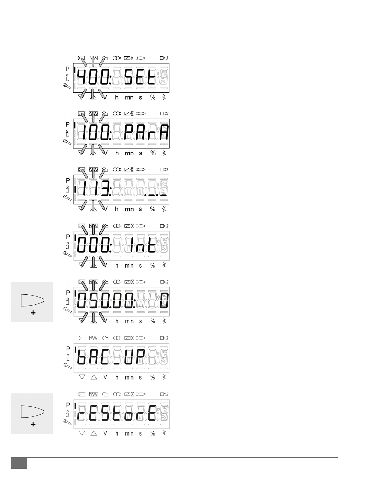
OPERATION EDRP-IOM-2019-0212 SECTION 3
Parameter Restore
1. Press and hold “F and A” until Code is displayed
a. Then enter unit national board number press enter
once complete.
2. “400: Set” will be displayed
a. Press the “-“arrow two times until “100: PArA” is
displayed.
b. Press the Enter button to get into “100” parameters.
c. Press the “+” arrow until parameter 113 is reach enter
into the parameter and record the Burner ID#.
d. This is required for performing the Restore process.
3. Restore procedure:
a. Go to “000: Int” parameter enter in and go to P-050 (050
will be ashing).
b. Press enter > bAC_uP is displayed.
c. Press “+” button to select “rEStorE”.
d. Press enter > 0 is displayed.
e. Press “+” button and 1 is ashing
f. Press enter, after about 5 seconds a 0 appears on the
display indicating the end of the backup process.
NOTE: If an error occurs during the Restore process, a
negative value is displayed. For troubleshooting, go
to error code 137 to view diagnostic code.
3-10
© Fulton Group N.A., 2019
Page 59

SECTION 3 EDRP-IOM-2019-0212 OPERATION
! WARNING
All information in this manual is for
reference and guidance purposes,
and does not substitute for required
professional training, conduct,
and strict adherence to applicable
jurisdictional/professional codes and
regulations.
Non-Fulton product information is for
reference purposes only. No Fulton
document should substitute for full
review of documentation available
from the component manufacturer.
Questions? Please Contact Your Local Manufacturer’s Representative
3-11
Page 60

OPERATION EDRP-IOM-2019-0212 SECTION 3
! WARNING
All information in this manual is for
reference and guidance purposes,
and does not substitute for required
professional training, conduct,
and strict adherence to applicable
jurisdictional/professional codes and
regulations.
Tampering with safety devices or
unauthorized bypassing of the boiler
control system will void the pressure
vessel warranty.
Using the Endura+ PURE Control™ Interface
Reference the Endura+ Installation and Operation Manual PURE Control™
Addendum for detailed instuctions on the controls system. The boiler control
system features an integrated color touchscreen display through which many
commissioning and operation tasks are performed, including temperature
control and multiple boiler sequencing setup. The graphical interface
is navigated by touch using your nger or a stylus. The screenshots and
information in this section will guide you through the menu screens.
Navigation
The control will enter a screensaver mode (shown below) after several minutes
with no interaction. Tap the screen to exit the screensaver.
The Menu screens are grouped into categories, and each serves a unique
function for changing parameters or viewing statuses. To change categories,
tap the desired category in the left sidebar menu. A navigation screen provides
access to screens within each category. Tap the “back” button to return to
category navigation.
3-12
© Fulton Group N.A., Inc. 2019
Page 61

SECTION 3 EDRP-IOM-2019-0212 OPERATION
A listing and functional description of each of the graphical icons found witrhin
the touchscreen menus is provided below in Table 10.
TABLE 10 GRAPHICAL ICON REFERENCE MENU
Button Function
Returns to the parent category.
Tap to display information based
on the screen currently selected.
Green: No alarm condition. Tap to
see Alarm History.
Yellow: Warning or Soft Alarm
active. Tap to see Alarm History.
Red: Alarm or Lock-Out active. Tap
to see Alarm History.
Green: Maintenance Inactive. Tap
to go to the Maintenance screen.
Yellow: Time For Service - Tap to go
to the Maintenance screen.
Green: Locked - Some screens may
not be accessible as congured
by the boiler plant administrator.
Tap the icon and enter the
administrative password to unlock.
! WARNING
All information in this manual is for
reference and guidance purposes,
and does not substitute for required
professional training, conduct,
and strict adherence to applicable
jurisdictional/professional codes and
regulations.
Non-Fulton product information is for
reference purposes only. No Fulton
document may substitute for full
review of documentation available
from the component manufacturer.
4 CAUTION
A temperature exceeding 120°F**
(48 C) in the boiler room may cause
premature failure of electrical
components. Provisions should
be made to maintain an ambient
temperature of 120°F** (48 C) or less
(the panel box interior should not
exceed 125°F** [51 C]).
**Pumps, PLC or ModSync panels may
require lower ambient temperatures or
additional cooling.
Yellow: Unlocked - Screens locked
by the boiler plant administrator
are now accessible. Tap the icon
again to lock. The screen will
automatically re-lock after 1-10
minutes (user adjustable).
Green: Lead/Lag Network Active.
Tap to enter Ethernet/IP Status.
Red: Lead/Lag Network
Communication Lost or
Recovering. Tap to enter Ethernet/
IP Status.
Gray: Lead/Lag Network Inactive.
Tap to enter Ethernet/IP Status.
Questions? Please Contact Your Local Manufacturer’s Representative
3-13
Page 62

OPERATION EDRP-IOM-2019-0212 SECTION 3
! WARNING
All information in this manual is for
reference and guidance purposes,
and does not substitute for required
professional training, conduct,
and strict adherence to applicable
jurisdictional/professional codes
and regulations.
Non-Fulton product information
is for reference purposes only. No
Fulton document should substitute
for full review of documentation
available from the component
manufacturer.
Endura+ PURE Control™ Menu Screen Functions
Boiler Control
General individual boiler and ancillary functionality is accessed through this
category.
` BOILER STATUS
The screen shown below summarizes information and sensor status for the
boiler.
` SAFETY DEVICE STATUS
Devices will either have a green circle to the left indicating closed circuit or a red
circle indicating the device is open. The device indicated as the “open limit” is the
rst device in the safety circuit open and should be the rst device addressed
during troubleshooting.
Once the boiler is full of water, the following test of low-water cuto can be accomplished:
1. Navigate to and tap the Test Low Water button on the screen.
2. Reset the Low Water condition by tapping the Reset Low Water button.
3. Perform appropriate test for any secondary Low Water controls.
` OPERATOR CONTROL
This screen is used for multiple functions: Start/Stop Deviations, Anti-Cycle
Timer, and Manual Burner Control.
The start and stop deviations instruct the burner when to enable and disable
around the setpoint temperature. Increasing the range will reduce cycling but
may result in larger temperature uctuations.
3-14
© Fulton Group N.A., Inc. 2019
Page 63

SECTION 3 EDRP-IOM-2019-0212 OPERATION
When in Automatic Control, the temperature controller will modulate the
burner to a ring rate necessary to achieve the setpoint. To enter Manual
Control, tap the “Automatic Control” button, and it will change to “Manual
Control.” Enter a “Manual Firing Rate” in the box, and press OK to conrm.
When nished with maintenance, return to this screen and place the boiler
back into Automatic Control.
The Anti-Cycle Timer, if used, will prevent the burner from ring for a minimum
amount of time between cycles
` BOILER HISTORY
Various data points of operational history are summarized on this screen.
` ALARM HISTORY
This screen provides a chronological list of alarms. Pressing the “View Alarm
Info” button will expand a selected alarm for additional information and
troubleshooting tips.
` MAINTENANCE LOG
Access a history of preventative maintenance and repairs. Tapping “View Entry”
will expand detail on a previous record. Add a record of service by tapping “New
Entry” and completing the record.
! WARNING
All information in this manual is for
reference and guidance purposes,
and does not substitute for required
professional training, conduct,
and strict adherence to applicable
jurisdictional/professional codes
and regulations.
Non-Fulton product information
is for reference purposes only. No
Fulton document should substitute
for full review of documentation
available from the component
manufacturer.
` ISOLATION VALVE
This screen will only be accessible if Isolation Valve is selected. See Auxiliary
Conguration in Admin.
The isolation valve can be placed in manual control or automatic. When using
manual, ensure all boilers are not placed in manual close while the system pumps
are in operation. In automatic control, a Close Delay Timer can be set to keep the
boiler’s isolation valve open for the prescribed time when a boiler no longer has a
call for heat. The Delta T Close Delay feature will hold the boiler isolation valve open
until residual heat is removed from the heat exchanger and the Delta T drops to the
selected value. When enabled, the isolation valve will not close until both conditions
are satised. One valve will always remain open when lead/lag is used.
` PRIMARY PUMP
This screen will only be accessible if Use Pump Control and Boiler Pump is selected.
See Auxiliary Conguration in Admin.
The purpose of this screen is to enable and disable a dedicated boiler pump
(primary pump) for Primary / Secondary piping arrangements only.
The pump can be placed in automatic control or manual. In automatic control,
the Stop Delay Timer will continue operating the pump for the prescribed time
after the call for heat ends. The Delta T Stop Delay will continue operating the
pump until residual heat is removed from the heat exchanger and the Delta T
drops to the selected value. When enabled, the pump will continue operation
until both conditions are satised.
Questions? Please Contact Your Local Manufacturer’s Representative
3-15
Page 64

OPERATION EDRP-IOM-2019-0212 SECTION 3
! WARNING
All information in this manual is for
reference and guidance purposes,
and does not substitute for required
professional training, conduct,
and strict adherence to applicable
jurisdictional/professional codes
and regulations.
Non-Fulton product information
is for reference purposes only. No
Fulton document should substitute
for full review of documentation
available from the component
manufacturer.
` SECONDARY PUMPS
This screen will only be accessible if Secondary Pumps is selected. See Auxiliary
Conguration.
Pumps may be congured to maintain either system delta-P or delta-T. Rotation
is automatic.
Lead/Lag
Integrated multiple boiler sequencing “Lead/Lag” is congured and monitored
through this category and Admin. Ensure the boilers are on a private Ethernet/IP
network shared with no other devices before continuing setup.
To function properly on the network, the Local Ethernet/IP Address of each
boiler must be specically set on the System Conguration screen in the Admin
category:
Boiler 1 – 192.168.1.100 Boiler 6 – 192.168.1.105
Boiler 2 – 192.168.1.101 Boiler 7 – 192.168.1.106
Boiler 3 – 192.168.1.102 Boiler 8 – 192.168.1.107
Boiler 4 – 192.168.1.103 Boiler 9 – 192.168.1.108
Boiler 5 – 192.168.1.104 Boiler 10 – 192.168.1.109
Physical wiring of the local boiler network uses Ethernet Port 1. Wiring for the
Ethernet/IP network will change based on the number of boilers in the system.
For systems with two boilers, a single shielded Ethernet cable can be wired
directly between the boilers. For systems with more than two boilers, each boiler
will need to have a shielded Ethernet home run back to the Ethernet switch
(ships loose in trim kit when ordered).
To enable Lead/Lag functionality, use the Auxiliary Conguration screen under
the Admin category. Set the Number of Boilers eld to the number of boilers
to be controlled. These steps must be completed at each boiler. Ensure the
Universal Data, also under Admin, is properly congured for data sources.
` LEAD/LAG CONFIGURATION
This screen is used to set sequencing preferences.
Lead/Lag priority determines how the boilers are sequenced, either by
cycles only, hours only, or an optimized algorithm.
Number of boilers displays how many boilers the Lead/Lag system expects
to have under control.
Lead start is how far below setpoint before the lead boiler turns on.
Lead stop is how far above setpoint before the lead boiler turns o.
3-16
The aggressive-passive slider determines how quickly lag boilers are
enabled. Slid all the way to the aggressive side, the last lag boiler will come
on when the control variable reaches 50%; all the way to the passive side,
the last lag boiler will come on at 90% control variable.
© Fulton Group N.A., Inc. 2019
Page 65

SECTION 3 EDRP-IOM-2019-0212 OPERATION
PID Control
Local PID and ring rate modiers are accessed in this category.
` LOCAL PID
Use the slider to set how passive or aggressive the control will act to meet
setpoint when the boiler is in local (standalone) mode. See Lead/Lag PID for PID
control of plants with multiple boiler sequencing.
` LOW FIRE HOLD
The boiler can be locked to low re rate after ignition for a set period of time. This
period of time can be enabled/disabled and adjusted on this screen.
` FREEZE PROTECTION
Two stages of freeze protection are provided. Stage 1 is only available if the boiler
(primary) pump is enabled in a primary secondary piping system. When the
boiler vessel water temperature falls below a congured temperature, the boiler
(primary) pump will be enabled until the set temperature has been reached.
Stage 2 enables the burner if the boiler vessel water temperature falls below a
congured temperature. The burner is held at low re until the set temperature
has been reached.
! WARNING
All information in this manual is for
reference and guidance purposes,
and does not substitute for required
professional training, conduct,
and strict adherence to applicable
jurisdictional/professional codes
and regulations.
Non-Fulton product information
is for reference purposes only. No
Fulton document should substitute
for full review of documentation
available from the component
manufacturer.
` OUTLET MONITORING
In addition to the mechanical Aquastat temperature high limit, the boiler
includes a digital control soft high limit available on the Outlet Monitoring
screen.
NOTE: If a high temperature condition occurs exceeding the high limit setting on
the mechanical Aquastat, the boiler will require a manual reset accomplished by
pressing the red Aquastat reset button.
The soft high limit acts to prevent nuisance manual reset high limit trips. If the
boiler outlet temperature exceeds the soft high limit, the burner will be driven to
low re until the outlet temperature is reduced to the value assigned in the Soft
Limit Reset.
` RATE OF CHANGE
When Rate of Change is enabled, the burner ring rate will slowly change
should a condition occur where the ring rate increases at a rate greater than as
permitted by the operator.
` COLD START
This feature allows the boiler to slowly reach temperature when receiving a
demand at a cold water condition as congured. When enabled, this modier will
take priority over the PID until the congured time or the congured boiler water
temperature is reached.
Questions? Please Contact Your Local Manufacturer’s Representative
3-17
Page 66

OPERATION EDRP-IOM-2019-0212 SECTION 3
! WARNING
All information in this manual is for
reference and guidance purposes,
and does not substitute for required
professional training, conduct,
and strict adherence to applicable
jurisdictional/professional codes
and regulations.
Non-Fulton product information
is for reference purposes only. No
Fulton document should substitute
for full review of documentation
available from the component
manufacturer.
Setpoint
The boiler or multiple boiler system will maintain supply water temperature
based on a setpoint temperature. This setpoint can come from a variety of
sources, including by calculation from an outdoor air temperature sensor, a
remote signal from the Building Management System (BMS), or from a static
manually entered setpoint.
` SETPOINT CONFIGURATION
The Setpoint Source screen allows for the selection between the various setpoint
sources available.
When in Outdoor Reset mode, the control will automatically calculate the
hydronic loop setpoint based on the settings congured on the Outdoor Reset
screen.
BMS Analog will monitor either the 4-20mA or 0-10VDC contacts for a remote
setpoint signal; the BMS Analog screens are used for the linearization settings for
the control signal.
When in BMS Network mode, the control will maintain setpoint based on the
Modbus RTU write point. Protocol conversion gateways are available for alternate
communication protocols including BACnet and LonWorks.
` OUTDOOR RESET
Outdoor air reset curves are congured through the Outdoor Reset screens. The
normal (occupied) setpoint curve and the setback (unoccupied) setpoint curve
are congured through separate screens.
The hydronic loop temperature setpoint will be calculated based on congured
outdoor air and setpoint high and low temperature values. When the outdoor air
temperature reaches a warm weather shutdown Outdoor Air Cuto temperature,
the boilers will be disabled until outdoor air temperature has decreased by the
value assigned in the Cuto Reset.
` BMS ANALOG 420MA AND 010VDC
High and low setpoint values must be assigned for correct linearization.
Scheduling
The Scheduling system allows for the operator to congure when the normal
(occupied) setpoint will be maintained. When outdoor reset is enabled, the
normal setpoint curve will establish setpoint during these time frames with the
setback (unoccupied) setpoint curve establishing setpoint for all other times. See
the Outdoor Reset screen in Setpoint.
3-18
© Fulton Group N.A., Inc. 2019
Page 67

SECTION 3 EDRP-IOM-2019-0212 OPERATION
Trending
Trending data is continuously recorded by the control and can be enabled or
disabled by the operator. Tap the “Next Curve” button to navigate through data
types.
Admin
Administrative functions are used during initial commissioning, troubleshooting
and other advanced tasks.
` SYSTEM CONFIGURATION
The System Conguration screen is used for saving (backup) and loading of
program settings. The time and date is also congured on this screen. The backup
battery status is shown in the bottom right of the screen. Loss of power without
an operational battery will result in lost program settings.
` SENSOR STATUS
An overview of boiler and auxiliary sensor status is available on this screen.
` AUXILIARY CONFIGURATION
! WARNING
All information in this manual is for
reference and guidance purposes,
and does not substitute for required
professional training, conduct,
and strict adherence to applicable
jurisdictional/professional codes
and regulations.
Non-Fulton product information
is for reference purposes only. No
Fulton document should substitute
for full review of documentation
available from the component
manufacturer.
Through this screen, the system type, setpoint sources, sensors, vent material,
and altitude are assigned. This must be individually congured for each boiler in
the network.
` UNIVERSAL DATA CONFIGURATION
The Universal Data system allows the boilers to share vital data over the Ethernet/
IP Boiler Network without having to wire individual sensors to each boiler, or
write commands to each boiler. Congure the Universal Data sources at each
boiler, for that specic boiler.
Physically Wired – The control will look to its own I/O inputs for the
information it needs and will then share that information with the Boiler
Network.
Boiler Network – The control will look to the local Ethernet/IP network for
the information it needs. In order for this to work, one boiler will need to
share that information with the network setup as either physically wired or
BMS network.
BMS Network – The control will look to the Building Management Network
for the information that it needs and will share it with the rest of the boiler
network.
Please note that each signal/sensor can be independently congured,
meaning one boiler could provide a setpoint to the boiler network, and
another could provide the system header temperature, for instance.
Questions? Please Contact Your Local Manufacturer’s Representative
3-19
Page 68

OPERATION EDRP-IOM-2019-0212 SECTION 3
! WARNING
All information in this manual is for
reference and guidance purposes,
and does not substitute for required
professional training, conduct,
and strict adherence to applicable
jurisdictional/professional codes
and regulations.
Non-Fulton product information
is for reference purposes only. No
Fulton document should substitute
for full review of documentation
available from the component
manufacturer.
` USER CONFIGURATION
An administrator password can be assigned to the control to prevent
unauthorized access. The selected screens will require entry of the administrator
password prior to access. The password may be up to 10 characters in length.
Commissioning Mode
The boiler must be placed in commissioning mode prior to adjusting combustion parameters. This screen is intended for trained factory authorized technicians. This allows easy access to locking the SAS valve, and adjustments to %O2
setpoint for the O2 Compensation system at the ring rate ranges. Place the SAS
Control into No Lock and tap the Complete Commissioning button when setup is
fully completed to return to normal operation.
Perform Test of Limit Controls
Fire the boiler and test the high limit control as follows:
1. Alter high temperature limit to a value lower than the anticipated loop
temperature. Turn the boiler on. Water temperature will rise until the
boiler locks out. This condition has to be manually reset.
2. Alter the high limit cut o temperature to normal level, typically 10-20
degrees above set point.
Perform Test of Low Gas Pressure Switch
Test the low gas pressure switch as follows:
1. With the boiler running turn up the low gas pressure switch until a lock out
is annunciated.
2. Return the switch to normal setting, re-start the boiler.
Perform Test of High Gas Pressure Switch
Test the high gas pressure switch as follows:
1. With the boiler running turn down the high gas pressure switch until a lock
out is annunciated.
2. Return the switch to normal setting, re-start the boiler.
General Operation of the Boiler
3-20
Excessive cycling will reduce the useful life of any piece of mechanical
equipment. Endura+ boilers should be operated and controlled so the boiler
cycles less than 12,000 times per year.
© Fulton Group N.A., Inc. 2019
Page 69

MAINTENANCE
INTRODUCTION
1
INSTALLATION
2
OPERATION
MAINTENANCE
3
4
Questions? Please Contact Your Local Manufacturer’s Representative
4-1
Page 70

MAINTENANCE EDRP-IOM-2019-0212 SECTION 4
! WARNING
All information in this manual is for
reference and guidance purposes,
and does not substitute for required
professional training, conduct,
and strict adherence to applicable
jurisdictional/professional codes and
regulations.
Prior to any maintenance concerning
electrical components of this
equipment, ensure electrical supply
to the equipment is disconnected.
Label all wires prior to disconnection;
wiring errors may cause improper
and hazardous operation.
Follow all proper lockout/tagout
procedures for service.
Before beginning any maintenance,
ensure area is free of any combustible
materials and other dangers.
What to do if you smell gas:
Do not try to light the appliance.
Do not touch any electrical switch.
Do not use any phone in the building.
Leave building and contact gas
supplier from neighbor’s phone. If you
cannot reach gas supplier, phone the
re department.
General
Your Endura+ boiler has been designed to provide years of trouble free
performance. To ensure continued safety and eciency of the boiler, please follow
the maintenance and inspection directions outlined in this section of the manual.
Daily, Weekly and Monthly Maintenance and Inspection are considered good
practice for any boiler, and is applicable to the full line of Endura+ boilers. It is
also good practice for any boiler installation to perform a thorough review of
the overall system on a regular basis, and after any maintenance procedures.
Any potential issues should be noted and followed up on to ensure safety and
reliability of all relevant equipment. System review items may include:
Looking for discoloration of any painted equipment, boiler jacket panels,
and/or insulation used in system piping.
Carefully checking for gas leaks using a combustible gas detector during
commissioning and regular inspactions; a Gasmate® 0119 or equivalent is
recommended. This includes, but is not limited to, gas delivery system, gas
train ttings, pressure switches, gas valves, regulators, conduit connections
to gas devices, and pre-mix delivery components.
Looking for evidence of leaks including the air intake/exhaust systems,
boilers, hydronic system piping, pumps, valves and other system
components.
Once boilers are running, making sure there are no ue gases around the
boilers, or in the boiler room.
NOTE: Combustion analysis and adjustment schedule can vary based on boiler
application and seasonal conditions. Biannual or quarterly adjustment may be
optimal in some applications—for example, systems operating as both winter
heat and summer reheat.
Daily Maintenance and Inspection Schedule
After initial start-up by qualied
personnel, linkage, control settings,
and fuel pressures should not be
readjusted.
4 CAUTION
All maintenance procedures should
be completed by trained personnel.
Appropriate training and instructions
are available from the Fulton Service
Department at (315) 298-5121 or
your local Fulton Heating Solutions
Representative.
In order to meet warranty conditions,
ensure all appropriate maintenance
activities are performed.
4-2
Daily maintenance and inspection must include the following:
1. Observe operating temperature and general conditions.
2. Verify that the ow of combustion and ventilating air to the boiler is not
obstructed.
3. Boiler area is free and clear of any combustible materials, including
ammable vapors and liquids.
Weekly Maintenance and Inspection Schedule
Weekly maintenance and inspection must include the following:
1. Observe the conditions of the main ame. Correct fuel/air adjustment
is essential for the ecient and reliable operation of this boiler. If an
adjustment to the combustion is necessary, the ue gas composition
should be checked with a carbon dioxide (CO2) or oxygen (O2) analyzer to
set conditions.
© Fulton Group N.A., Inc. 2019
Page 71

SECTION 4 EDRP-IOM-2019-0212 MAINTENANCE
Monthly Maintenance and Inspection Schedule
Monthly maintenance and inspection must include the following:
1. Test high-limit control by reducing setting below the operating
temperature; burner should shut o. After readjusting the setpoint, reset
the control.
2. Test operating temperature control by reducing temperature setting as
necessary to check burner operation.
3. Check ue gas temperature at outlet. If there is a temperature increase
over previous readings, the probable cause is soot or water-scale build-up
on the tubes. Consult your Fulton representative immediately if there is a
concern.
4. Test low gas pressure switch and high gas pressure switch utilizing the
procedure in Operation section of this manual.
5. Inspect the combustion air inlet lter. If dust, lint or debris has accumulated
such that the lter appears heavily loaded visually, replace the lter
immediately.
Replacing the Combustion Air Inlet Filter
! WARNING
All information in this manual is for
reference and guidance purposes,
and does not substitute for required
professional training, conduct,
and strict adherence to applicable
jurisdictional/professional codes and
regulations.
Never use open ame or other sources
of ignition to check for gas leaks.
Ensure boiler is o and cooled with
proper lockout-tagout per local codes
prior to service and maintenance.
4 CAUTION
Use caution when using any cleaning
solutions. Refer to local regulations for
proper cleaning solution disposal.
The combustion air inlet lter must be replaced at a minimum once per year.
Active construction sites and installations with high airborne contaminants will
require more frequent replacement.
Proceed as follows:
1. Remove the lter. The lter sits in the slot on the suction side of the blower
inside the boiler cabinet.
2. If debris has plugged or contaminated the lter, the lter must be replaced.
NOTE: Operating the burner with the combustion air inlet lter removed will void
the burner warranty. A clean lter of the same Fulton part number (type, size and
style) must be installed while the boiler is in operation.
3. Return the lter to its original position in the slot, verify orientation.
Replacing or Updating the Boiler Control
Only update the software or rmware when directed by the factory. Lead/Lag
integration requires the same rmware and software version on all units.
Do not allow oil leaks, dust, or dirt to
accumulate around the boiler.
Questions? Please Contact Your Local Manufacturer’s Representative
4-3
Page 72

MAINTENANCE EDRP-IOM-2019-0212 SECTION 4
! WARNING
Personnel performing burner
assembly maintenance must wear
appropriate respiratory protection.
Failure to do so may result in the
inhalation of refractory ceramic
bers.
4 CAUTION
All information in this manual is for
reference and guidance purposes,
and does not substitute for required
professional training, conduct,
and strict adherence to applicable
jurisdictional/professional codes and
regulations.
All maintenance procedures should
be completed by trained personnel.
Appropriate training and instructions
are available from the Fulton Service
Department at (315) 298-5121 or
your local Fulton Heating Solutions
Representative.
Annual Maintenance and Inspection Schedule
Annual maintenance and inspection must be performed prior to each heating
season, and includes but is not limited to the following tasks, which must be
done by a factory trained technician:
1. Inspect the fuel train, burner and control panel to be sure components are
free of debris and are properly attached to the boiler.
2. Replace the combustion air inlet lter with a new lter of the same Fulton
part number (type, size and style).
3. Inspect exible premix couplings; replace immediately if damaged or
worn.
4. Examine the venting system (air intake and exhaust piping):
Check all joints and pipe connections for tightness.
Check piping for corrosion or deterioration.
Check that the piping is clear of debris.
Check that the condensate drain system is functioning.
5. Inspect the hydronic heating system for other problems.
6. Leak test the gas valves.
7. Clean the low water cut-out probe on the water outlet pipe. This can be
accessed via the top removable panel.
In order to meet warranty conditions,
ensure all appropriate maintenance
activities are performed.
Burner gaskets must not be reused.
Gaskets are designed for one-time use
only.
Using nuts and washers not provided
by Fulton can lead to ue gas leakage
and cause damage to the studs.
Follow proper safety precautions when
using a ladder.
8. Remove and inspect burner. Clean as necessary. See Removing,
Inspecting and Cleaning Burner section of this manual.
9. Test relief valve per manufacturer instructions by lifting the lever for 5
seconds and allowing the valve to snap shut. Please see the manufacturer’s
recommendations on the relief valve tag.
10. Perform combustion analysis and adjust if necessary. A low O level,
resonance or harmonic can indicate a need for burner service.
11. Replace the O sensor with a new sensor. Press “Reset O” on the
Maintenance screen.
O2 Compensation Measurement
The Fulton authorized service technician’s gas analyzer measures O% after ue
gas moisture removal, while the boiler O sensor measurement is made without
removal of the moisture. For operator convenience, the boiler O sensor “wet”
value is approximated to a “dry” value for control screen display purposes. This
approximation may deviate from the test apparatus; the compared values should
be within ±1.0% O. Discrepancies may be observed if the technician’s gas analyzer
has not been properly calibrated per manufacturer instructions and time interval.
NOTE: THE O COMPENSATION READOUT IS NOT A REPLACEMENT FOR A
CALIBRATED FLUE GAS ANALYZER. Under no circumstances should the O
compensation readout value be used for combustion adjustment and verication; a
calibrated ue gas analyzer is required.
4-4
© Fulton Group N.A., Inc. 2019
Page 73

SECTION 4 EDRP-IOM-2019-0212 MAINTENANCE
Removing, Inspecting and Cleaning Burner
For the following procedure, be sure to reference Figures 25 and 26.
1. A burner maintenance parts kit is required to complete the following
steps. Contact your Fulton representative to purchase this parts kit before
proceeding, please have your National Board number ready to expedite
service.
2. EDR+2500/3000 Only: Access to the burner is provided through the top of
the cabinet, removing a side panel will facilitate access.
3. EDR+4000-6000 Only: Access to the burner is provided through the front
cabinet door.
4. Loosen the hose clamps on exible couplings and remove the premix
elbow.
5. Remove safety and control devices from the burner ange, including the
ignition assembly, UV ame scanner, and O bypass line.
6. Loosen and remove the nuts and washers from the burner ange. Take
care to properly handle and store the hardware during maintenance.
NOTE: Due to unique hardware specications, alternate hardware must not be
substituted. If hardware is lost or damaged, contact your Fulton representative
for replacements.
! WARNING
Specied torque values are mandatory
to ensure safe and reliable oeration of
the boiler. Failure to properly torque
hardware may result in PERSONAL
INJURY, DEATH, or property damage.
O bypass line is hot; contact with
ammable materials can cause a re.
Do not touch or work on the O system
while hot.
THE O COMPENSATION READOUT
IS NOT A REPLACEMENT FOR A
CALIBRATED FLUE GAS ANALYZER.
Under no circumstances should the O2
compensation readout value be used for
combustion adjustment and verication;
a calibrated ue gas analyzer is required.
7. Carefully remove the burner from the combustion chamber and cabinet,
taking precaution to ensure the burner metal ber material does not
make contact with any other surfaces.
NOTE: Do not use liquids or brushes when cleaning the burner.
8. Visually inspect the interior and exterior of the burner for debris. If debris
is present, use a compressed air blow gun with air pressure of 30 psi (2
bar) to maximum 72.5 psi (5 bar). The blow gun must be a minimum 0.40
inches (1 cm) from the surface of the burner. Carefully vacuuum debris
from the inside of the burner.
NOTE: The combustion air supply must meet the requirements detailed in
the Installation section. Combustion air contaminants can lead to excessive
maintenance or damage to burner components. The MERV 8 lter will capture
90+% of particles from 3-10 microns, but a small percentage will pass through
to the burner head. Installations with poor combustion air quality may require
burner cleaning more frequently than the annual service. A dirty burner may
experience audible combustion harmonics within the normal operating range,
requiring a need for cleaning. Damage due to poor combustion air quality is not
covered under the warranty. A damaged burner will require replacement.
Questions? Please Contact Your Local Manufacturer’s Representative
4-5
Page 74

MAINTENANCE EDRP-IOM-2019-0212 SECTION 4
! WARNING
THE O COMPENSATION READOUT
IS NOT A REPLACEMENT FOR A
CALIBRATED FLUE GAS ANALYZER.
Under no circumstances should the
O2 compensation readout value be
used for combustion adjustment
and verication; a calibrated ue gas
analyzer is required.
9. Carefully reinstall the burner: Replace both burner gaskets, do not reuse
the burner gaskets. Apply C5-A Antiseize (PN 2-12-000191) to threads, and
reinstall the burner ange washers and nuts using only originally supplied
or genuine Fulton replacement hardware. Tighten in a star pattern.
EDR+2500/3000 Only: Verify torque to 23 ft-lbs.
EDR+4000-6000 Only: Verify torque to 20, 40, then 45 ft-lbs. in
three stages. A 6-point 7/8” crowfoot socket wrench is required.
10. Reinstall the ignition assembly with a new O-ring using Parker Super-OLube and apply C5-A Antiseize (PN 2-12-000191) to screws.
EDR+2500/3000 Only: Verify torque to 27 in-lbs. Apply
Permatex 22058 di-electric grease to electrical connections.
NOTE: Fulton recommends annual replacement of the EDR+2500/3000 ignitor.
Always inspect the ignitor for small ceramic cracks, corrosion on any of the
electrical connectors, and dimensional drift on the spark gap. If any of these are
found, the ignitor must be immediately replaced.
EDR+4000-6000 Only: Verify torque to 60 in-lbs.
NOTE: The ignition electrode on the EDR+5000/6000 pilot assembly requires
annual inspection, but is not intended to be replaced on an annual basis. See
Inspecting the Pilot Ignition Assembly.
11. Reinstall the O sensor and verify torque to 26-33 ft-lbs. Reconnect the O
bypass line. Ensure sensor wiring cannot contact the bypass line.
NOTE: The O sensor is intended to be replaced annually. Sites with air
contaminants such as silicone/RTV use in the boiler room may requirement more
frequent replacement due to sensor poisoning. Use of “sensor safe” silicones/RTV
is required.
12. Reinstall and hand tighten the UV scanner. EDR+2500/3000 Only: Verify
wiring is below the top cabinet panel.
13. Reinstall pre-mix elbow exible coupling and tighten hose clamps.
EDR+2500/3000 Only: Verify torque to 40 in-lbs.
EDR+4000-6000 Only: Verify torque to 45 in-lbs.
14. Reinstall cabinet panels.
15. Perform a full combustion analysis and adjust if necessary.
4-6
© Fulton Group N.A., Inc. 2019
Page 75

SECTION 4 EDRP-IOM-2019-0212 MAINTENANCE
Inspecting the Pilot Ignition Assembly
NOTE: This section applies only to Endura+ boilers equipped with a pilot ignition.
The pilot assembly requires annual inspection; although it is considered a wearitem it is not intended to be replaced on an annual basis.
1. Remove the pilot ignition assembly from the burner ange.
2. Inspect for corrosion in the raja connector on the pilot and on the ignition
wire. Replace if found.
3. Inspect insulator for cracks, dirt, oils or soot. Clean if necessary. Replace if
any cracks are found or it cannot be cleaned.
4. Verify that the pilot orice is clean. Clean if obstructed.
5. Verify that the spark gap to the tube is 3/16” (4.763 mm) within tolerance +/1/16” (1.588 mm), adjust if needed.
6. Inspect that the insulation block around the pilot when installed has not
lost structural integrity. Replace with original Fulton part if needed.
7. Reinstall the pilot ignition assembly per the instructions detailed in
Removing, Inspecting, and Cleaning Burner.
After All Repairs and Maintenance
1. Perform all Safety Checks as described in the Operation section.
2. Fire the boiler and perform a full combustion verication. Make
adjustments as necesary.
3. Complete the “Installation and Operation Report” for Endura+ boilers and
retain in the boiler’s maintenance records.
NOTE: Accurate and complete combustion and maintenance records detailing
compliance with the Installation, Operation and Maintenance Manual must be
produced for warranty consideration.
Questions? Please Contact Your Local Manufacturer’s Representative
4-7
Page 76

MAINTENANCE EDRP-IOM-2019-0212 SECTION 4
BILL OF MATERIAL
DESCRIPTIONPART NUMBERITEM
3/4" NPT SIGHT OBSERVATION PORT2-12-0000121
LOCTITE C5-A COPPER ANTI-SEIZE2-12-0001912
029 1/16" AFLA S O-RING 1 5/8" OD (MCMASTER #5240T215)2-12-315003
EDR+ 3000 BU RNER TO PV GASKET2-12-3150057
EDR+ 3000 PREMIX TO BURNER GAS KET2-12-3150079
EDR+ 3000 SPARK IGNITION ASS EMBLY2-20-315100
3/8-16 NiCu400 HEX NUT (MONEL400)2-22-00015627
3/8" BELLEV ILLE WASHER (INCON EL 718,.385" ID X 1.25" OD X .125" THK, .021" DISH)2-22-00035331
10-32 X 1/4" LONG S.S. TORX SCREW (MCMASTER #96710A572)
3/4" - 14 NPSM THERMAL BARRIER FOR FLAME DETECTOR2-40-00046473
SIEMENS LMV 2-3 HIGH SENSITIVITY UV SCANNER2-40-00110774
EDR+ 3000 BU RNER2-40-31500076
NPD - 02 SENS OR (BOSCH LSU ADV WIDEBAND LAMBDA SE NSOR)2-45-31550192
EDR+ 3000 PREMIX RETAINER
PLATE2-50-31511199
EDR+ 2500 / EDR+ 3000 BURNER VOLUME REDUCER / PREMIX INLET ASSEMBLY5-10-315300105
INSTALL 2" DURABLANKET (2-12-880103) BETWEEN
THE HEAT SH IELD AND THE TOP FLANGE OF THE
FURNACE IN AREAS SHOWN. BE SU RE THAT
NO INSULATION PROTRUDES PAS T THE INSIDE
DIAMETER OF THE TOP FLANGE AND NOT PAST
ANY CUTOUTS THROUGH THE TOP FLANGE.
ONCE INSULATION IS IN PLACE USE RIGIDIZER
(2-12-000196) ON THE EXPOSED INSULATION.
INSULATION INSTALLATION DETAIL
5
11
2-22-31502136
Bill of Material
Item Part Number Description
1 2-12-000012 3/4” NPT Sight Observation Port
2 2-12-000191 Loctite C5-A Copper Anti-seize
5 2-12-315003 029 1/16” AFLAS O-Ring 5/8” OD
7 2-12-315005 EDR+ 3000 Burner to PV Gasket
9 2-12-315007 EDR+ 3000 Premix to Burner Gasket
11 2-20-315100 EDR+3000 Spark Ignitiion Assembly
27 2-22-000156 3/8-16 NICu400 Hex Nut
31 2-22-000353
36 2-22-315021 10-32 x 1/4” Long S.S. Torx Screw
73 2-40-000464 3/4” - 14 NPSM Thermal Barrier for Flame Detector
74 2-40-001107 Siemens LMV2-3 High Sensitivity UV Scanner
76 2-40-315000 EDR+3000 Burner
92 2-45-315501 O2 Sensor
99 2-50-315111 EDR+3000 Premix Retainer Plate
105 5-10-315300 EDR+2500/3000 Burner Volume Reducer/Premix Inlet Assembly
3/8” Belleville Washer (Inconel 718, .385” ID x 1.25” OD x .125 THK, .021” Dish)
WASHER ORIENTATION DETAIL
(SHOWN PR ETORQUE FOR CLARIFICATION)
BELLEVILLE WASHERS MUST BE IN STALLED
IN THE ORIENTATION SHOWN.
31
APPLY PARKER SU PER-O-LUBE
DURING INSTALLAT ION
74
73
5
APPLY LOCTITE COP PER C5-A ANTI-SEIZE
36
11
(2-12-000191), & TO RQUE TO 27 IN. LBS.,
(TYP. 2 PLCS.)
APPLY LOCTITE C OPPER C5-A ANTI-SEIZE (2-12-0001 91),
1
TIGHTEN 1.5 - 3.0 TURNS PA ST FINGER TIGHT
TORQUE TO 26-33 FT. LBS.
92
APPLY LOCTITE C5 -A COPPE R ANTI-SEIZE (2-12-000191) TO
THREADS WHEN IN STALLING 02 BYPASS TUBE. FULLY IN SERT
TUBE INTO FITTING , TIGHTEN THE NUT UNTIL THE TUBE
WILL NOT TURN O R MOVE AXIALLY. THEN TIGHTEN
FITTING 1 1/4 MORE REVOLUTIONS
APPLY LOCTITE C5 -A COPPER ANTI-SEIZE
(2-12-000191), & TO RQUE TO 23 FT. LBS.
(SEE WASHER ORIE NTATION DETAIL VIEW
27 31 2
FOR PROPER BELLEV ILLE WASHER
INSTALLATION, (T YP. 12 PLCS.)
(2 PC.)
99
105
9
BE SURE THE COR RECT GASKET AND
ORIENTATION IS US ED AT THIS LOCATION
76
7
BE SURE THE COR RECT GASKET AND
ORIENTATION IS US ED AT THIS LOCATION
4-8
FIGURE 25 EDR+ 2500/3000 BURNER ASSEMBLY
© Fulton Group N.A., Inc. 2019
Page 77

SECTION 4 EDRP-IOM-2019-0212 MAINTENANCE
BURNER / PREMIX ASSEMBLY
BILL OF MATERIAL
T NUMBER
2-000012
2-000721
2-315008
2-315011
2-000058
2" - 3" STEEL WORM DRIVE HOSE CLAMP (MCMASTER # 5 407K22)
2-315006
1/2" BELLEVILLE WA SHER (SS301, 0.519"ID x 1.24"OD x 0.125"THK (SOLON#820125301)
2-315039
1/4-20 X 5/8" LONG S.S. TORX SCREW (MCMASTER #90 600A128)
2-315040
3/4" - 14 NPSM THE RMAL BARRIER FOR FLAME DETECT OR
0-000464
0-001107
0-315600
NPD - 02 SENSOR (BO SCH LSU ADV WIDEBAND LAMBDA SENSOR)
5-315501
0-315310
EDR+ 6000 BURNER VOLUME REDUCER/ PREMIX INLET A SSEMBLY
0-315315
0-315675
0-315680
0-315694
2-880103) BETWEEN
TOP FLANGE OF THE
OWN. BE SURE THAT
ES PAST THE INSIDE
ANGE AND NOT PAST
GH THE TOP FLANGE .
LACE USE RIGIDIZER
XPOSED INSULATIO N.
BELLEVILLE WASHERS MUST BE INSTALLED
IN THE ORIENTAT ION SHOWN.
D
N.
WASHER ORIENTATIO
(SHOWN PRETORQUE FOR CLARIFICATION)
Bill of Material
Item Part Number Description
1 2-12-000012 3/4” NPT Sight Observation Port
2 2-12-000721 029 1/16” Vitton O-Ring 1.625 OD
4 2-12-315008 2” ID x 6” Neoprene Flexible Coupling
6 2-12-315011 EDR+ 6000 Premix / Furnace Gasket
25 2-22-000058 1/2-13 Hex Nut, GR. 2H
34 2-22-315006 2” - 3” Steel Worm Drive Hose Clamp
41 2-22-315039 1/2” Belleville Washer (SS301, 0.519” ID x 1.24” OD x 0.125” THK
42 2-22-315040
1/4-20 x 5/8” Long S.S. Torx Screw
70 2-40-000464 3/4” - 14 NPSM Thermal Barrier for Flame Detector
73 2-40-001107 Siemens LMV2-3 High Sensitivity UV Scanner
76 2-40-315600 EDR+6000 Mesh Burner
89 2-45-315501 O2 Sensor
95 5-10-315310 250 Hz Resonator Capped Tube
96 5-10-315315 EDR+6000 Burner Volume Reducer/Premix Inlet Assembly
107 5-10-315675 EDR+6000 Premix Retainer Plate
110 5-10-315680 EDR+6000 Pilot Assembly
119 5-10-315694 EDR+6000 Pilot Insulation
AN ALTERNATE TOO L MUST BE USED
TO TORQUE THESE TWO NUTS. BE
SURE TO ADJUST TORQUE WRENCH TO
ACCOMODATE THE CHANGE OF GEOMETRY.
6 76 6 96 107
41
BELLEVILLE WASHERS MUST BE INSTALLE
IN THE ORIENTATION SHOW
N DETAIL
(2 PCS.)
APPLY LOCTITE COPP ER C5-A ANTI-SEIZE (2-12-000191 ),
1
TIGHTEN 1.5 - 3.0 T URNS PAST FINGER TIGHT
70
73
APPLY LOCTITE COP PER C5-A ANTI-SEIZE
(2-12-000191), & TO RQUE TO 60 I
42
(TYP. 2 PLCS.)
110
APPLY PARKER SUP ER-O-LUBE
2
DURING INSTALLATI ON
ITEM
1
2
4
6
25
34
41
42
70
73
76
89
95
96
107
110
119
N. LBS.,
INSTALL 2" DURABL ANKET (2-1
THE HEAT SHIELD A ND THE
FURNACE IN AREAS SH
NO INSULATION PR OTRUD
DIAMETER OF THE TOP FL
ANY CUTOUTS THR OU
ONCE INSULATION IS IN P
(2-12-000196) ON THE E
PAR
2-1
2-1
2-1
2-1
2-2
2-2
2-2
2-2
2-4
2-4
2-4
2-4
5-1
5-1
5-1
5-1
5-1
Questions? Please Contact Your Local Manufacturer’s Representative
APPLY LOCTITE CO PPER C5-A ANTISEIZE
(2-12-000191) TO THREADS WHEN
INSTALLING 02 BYP ASS TUBE. TRIM
1" OFF 02 LINE THEN FULLY INSERT
TUBE INTO FITTING , TIGHTEN THE NUT
UNTIL THE TUBE W ILL NOT TURN OR MOVE
AXIALLY. THEN TIG HTEN FITTING 1 1/4 MORE
REVOLUTIONS.
FIGURE 26 EDR+ 40006000 BURNER ASSEMBLY
89
TORQUE TO 26 - 33 FT. LBS.
APPLY LOCTITE CO PPER C5-A ANTI-SEIZE (2-12-000191 ),
& TORQUE TO 45 FT. LBS. IN THREE STAGES
25
(SEE WASHER ORI ENTATION DETAIL VIEW FOR
41
PROPER BELLEVI LLE WASHER
INSTALLATION, (TY P. 14 PLCS.)
(TORQUE SPEC: 20 IN. LBS.)
34
95
4
34
(TORQUE SPEC: 20 IN. LBS.)
4-9
Page 78

MAINTENANCE EDRP-IOM-2019-0212 SECTION 4
Troubleshooting
Use the following tables as a guide to troubleshooting your boiler.
PROBLEM CAUSE CHECK
Control does not illuminate 24 VDC Power Supply Check fuse or circuit breaker. Reset or replace as
necessary.
Fan will not start High temperature is tripped 1. Check sensor wiring connector.
2. Check resistance.
3. Replace sensor if faulty.
Low gas is tripped 1. Reset switch, making sure to listen for audible
click.
2. Replace switch if setting is below actual pressure.
High gas is tripped 1. Reset switch, makiing sure to listen for audible
click.
2. Replace switch if setting is above actual pressure.
Flame detector has detected light/scanner 1. Identify light source, remove
2. Replace ame detector
Air switch is made when fan is not on 1. Adjust, if necessary.
2. Reset switch
3. Replace switch
Blower contactor made when fan not on Replace motor contactor
Gas valve proof of closure defective Replace valve
Loose wire connection Check wiring
High Back Pressure Switch
trip/boiler shutdown
Main ame failure during
ring period
Ignion Failure If UV scanner does not detect the ame during the
VFD Manual Lockout aer
Power Outage
Excessive Vent Pressure This condion will automacally recycle, so the
boiler will try to relight. The venng should be
checked for obstrucons and cleaned. Check
switch seng.
Main gas control valve is de-energized and the control goes into “lockout” mode. Flame failure occurs
and the indicator is illuminated.
4-second trial-for-ignion period, the gas valve and
spark ignion are de-energized. At this me a safety
lockout occurs.
A power outage greater than 15 seconds but less
than 25 seconds.
The programmer must be manually reset. Check
wire connecons.
Idenfy and correct.
Reset the VFD lockout.
4-10
© Fulton Group N.A., Inc. 2019
Page 79

SECTION 4 EDRP-IOM-2019-0212 MAINTENANCE
PROBLEM CAUSE CHECK
Main ame fails Ignition issue 1. Visually verify spark.
2. Replace igniter or transformer, as needed.
Gas valve not set properly Verify the last elbow gas pressure matches the start
up report.
Flame detector failure 1. Visually verify the ame through the sight glass.
2. Remove ame detector and visually verify the
ame through the scanner tube.
3. Verify the ame detector eye is not dirty.
4. Replace scanner.
Insucient Gas Supply 1. Verify the manual shut-o valves are open,
allowing gas ow through the gas train.
2. Adjust incoming gas pressure to match the start
up report.
Gas Filter Blocked Replace gas lter.
Air supply blocked Verify venting is not obstructed and lter is not
plugged.
Boiler fails while
modulating
Poor combustion Gas valve not set properly Adjust gas valve settings.
Manual Reset limit device
trips
Power outage to the boiler
room
Gas Pressure alarm is
annunciated
Gas valve not set properly Verify the last elbow matches the start up report.
Air supply blocked (direct vent only) Verify venting is not obstructed.
Manual Reset Limits include: Flame safeguard, high
or low gas pressure, high temperature limit
Entire boiler system is disabled and de-energized. When power has returned, the boiler will have to be
Either insucient gas pressure or the gas pressure
to the manifold is too high for safe and proper
operation of the boiler. This shuts down the burner.
When gas pressure is restored, the annunciated
alarm will remain on and the boiler will remain
locked out until the gas pressure switch is manually
reset.
DO NOT reset without determining and correcting
the cause.
manually reset, as it will be in the lockout position
Locate cause and correct. In the event of a high
gas manifold pressure condion, qualied service
personnel must correct the problem before
restarng the boiler.
High water temp alarm is
annunciated
Burner harmonic or
resonance
Questions? Please Contact Your Local Manufacturer’s Representative
Boiler water has exceeded both the operating and
high-limit temperature. When the water temperature
falls below the high-limit temperature, the boiler will
remain locked out until the controller is manually
reset.
Improper combustion parameters or fouled lter or
burner.
Locate cause and correct. Once the control is reset,
the sequence returns to normal operation provided
that the other limits are satised.
1. Inspect air lter, replace if dirty.
2. Inspect burner, clean according to maintenance
instructions if dirty.
3. Verify combustion at all operating points.
4. Proceed to resonator adjustment ONLY AFTER
verifying he above. Consult factory for resonator
adjustment.
4-11
Page 80

MAINTENANCE EDRP-IOM-2019-0212 SECTION 4
4-12
© Fulton Group N.A., Inc. 2019
Page 81

PAGE INTENTIONALLY LEFT BLANK
Page 82

No part of this Installation, Operation, and Maintenance manual
may be reproduced in any form or by any means without
permission in writing from Fulton Group N.A., Inc.
Fulton Boiler Works, Inc., Fulton Heating Solutions, Inc. & Fulton Thermal
Corporation are part of Fulton Group N.A., Inc., a global manufacturer of steam,
hot water and thermal uid heat transfer systems.
© Fulton Group N.A., Inc. 2019
Fulton Heating Solutions
6288 Running Ridge Road, Syracuse, NY 13212
Call: (315) 298-5121 • Fax: (315) 298-6390
The heat transfer innovators
www.fulton.com
EDRP-IOM-2019-0212
 Loading...