

Page 1

__________________________________________________________
Note: This document is to be used in conjunction with the applicable Installation, Operation, and
Maintenance Manual. Content subject to change without notice.
TABLE OF CONTENTS
Lead/Lag Outdoor Reset Configuration Using Communication Port 2 (second display port)
Stand Alone Boilers Controlled by a Third Party Control
Gateways
Setup for the Sola 7999D display of Com 2 for BMS Communication
Protocol Gateway Setup Guide
BACnet UDP IP / MSTP / Metasys N2 Module: General and Connection Overview
Lonworks Module: General and Connection Overview (Bacnet is the only option for Pulse
boilers)
Module Dipswitch Overview
Module Service Pin (Lonworks Module Only)
Downloading New Configuration Files
Connection Help
Setting the Static IP Address
Temporarily Disabling the Wireless Connection
Connection Troubleshooting
Node Address Setup
Baud Rate Settings
Modbus to Bacnet Pre-Loaded Gateway Points
Lead/Lag Outdoor Reset Configuration Using Communication Port 2 (second
display port)
If the boilers are set up to be lead/lag with outdoor reset, all the communication connections on the
J3 plug of the Sola control will be used. The third party control can be wired to the Sola display on
communication port 2. If requested at the time of the boiler order, the communication port will be
activated at the factory. Only the baud rate may have to be changed in the field. When multiple
boilers are configured for a system for lead/lag outdoor reset, only the master boiler needs to have
_____________________________________________________________________________________
Questions? Call (315) 298-5121 or visit us online at www.fulton.com
©The Fulton Companies 2013
Supplement SOLA-IOM-2013-0220
Page 2

__________________________________________________________
the third party connection. The lag boiler(s) points that can be viewed through the master are
limited, so please review the Modbus to Bacnet Pre-Loaded Gateway Points that would be in the
master boilers gateway to see if they are sufficient for your application. Please refer to electrical
diagram in manual, which shows wiring connection to the display's communication port 2.
Return to Table of Contents
Stand Alone Boilers Controlled by a Third Party Control
If the boilers are not set up to be lead/lag outdoor reset, a third party control can land the boilers’
connection to J3, MB1 on the Sola control. If this is known at the time the boiler order is entered,
the control will be set up for this type of control. Please refer to electrical diagram in manual for J3,
MB1 connections. The communication wires can be daisy chained to each boiler.
Return to Table of Contents
Gateways
Fulton offers (as an option) a Modbus to Bacnet gateway. The gateway will come pre-programmed
and wired in one, or if desired, all of the boilers. If the boilers are daisy chained together through J3,
MB1, one gateway can be used on the master boiler which will be wired to communication port 2 of
the master display. Please refer to Setup for the Sola 7999D display of Com 2 for BMS
Communication to verify setup or initial setup of Com 2 port.
and set-up instructions.
Note: Although there are many points that are available through Modbus, not all of them should be
considered to be continuously written to, all writes should be on a change only. There are specific
write addresses that will fill an internal Sola control EEPROM that should not be continuously written
to. Also all the information out of the control is in Celsius; this may have to be converted to
Fahrenheit if desired. Firing rate also requires a conversion.
Return to Table of Contents
Setup for the Sola 7999D display of Com 2 for BMS Communication
The following information will help set-up for communication when using a Sola control with a
Protonode Gateway (Modbus to Bacnet).
_____________________________________________________________________________________
Questions? Call (315) 298-5121 or visit us online at www.fulton.com
©The Fulton Companies 2013
Supplement SOLA-IOM-2013-0220
Page 3

__________________________________________________________
Note: If a Proto node Gateway is being used, it was fully programmed at the Fulton Factory and
should not require any changes on the Sola side. The customer connection side of the gateway may
require dip switch changes for baud rate and the required address. See the end of these instructions
for information on customer gateway setup.
1. From the Home Screen press Setup
2. Then Press Display setup
3. Then press tab Com 2
- Check the Enable box
- Choose baud rate if known or if a Proto Node Gateway is being used it should be 19,200
- Press the save button
4. Then press the Gateway tab
- Check Enable Modbus gateway
- Press Gateway on COM2 Port
- Press Save
5. Press the upper right Arrow to back out
6. Press Control Setup
7. Press Change Address
8. Password "sola" is required
- Change the address to the required address
o If Protonode is used, Com 1 will be preset to address 2 on all boilers.
Note: The address in Yellow will say Com 1, Com 1 is an actual pass through of the
communication when a BMS is communicating directly to Com 2 through Modbus or a
Gateway. Any communication will "piggy back" on all the standard communication from
the display to the Sola base. Changing this address will not affect the communication
between the Display and the Sola.
9. Back out to the Home Screen and press the Sola
- Press Configure
- Press System Identification and Access
o When you change the above Com address the Sola will change the MB1 and
MB2 address. If boilers are being daisy-chained together through MB1 the
address will need to be changed back to what it was. For example: If the BMS is
communicating with is the Master boiler, MB1 should be 1, the next boiler MB1
would be 2 and so on up to 8 boilers.
Return to Table of Contents
_____________________________________________________________________________________
Questions? Call (315) 298-5121 or visit us online at www.fulton.com
©The Fulton Companies 2013
Supplement SOLA-IOM-2013-0220
Page 4

__________________________________________________________
_____________________________________________________________________________________
Questions? Call (315) 298-5121 or visit us online at www.fulton.com
©The Fulton Companies 2013
Supplement SOLA-IOM-2013-0220
Page 5
__________________________________________________________
Protocol Gateway Setup Guide
Return to Table of Contents
_____________________________________________________________________________________
Questions? Call (315) 298-5121 or visit us online at www.fulton.com
©The Fulton Companies 2013
Supplement SOLA-IOM-2013-0220
Page 6
__________________________________________________________
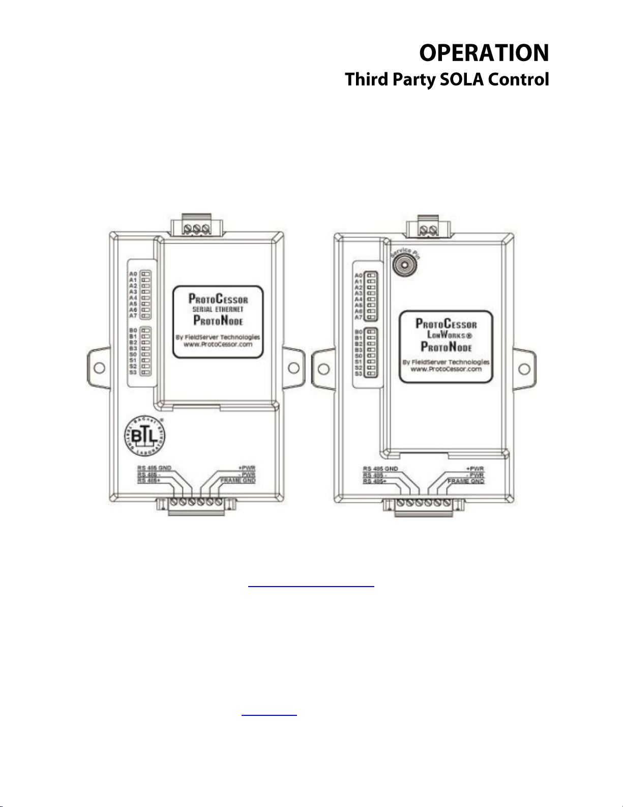
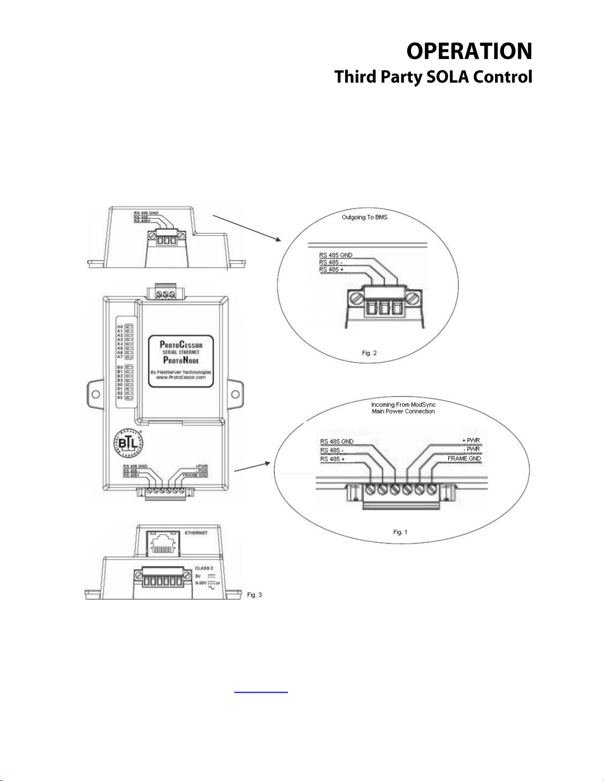
BACnet UDP IP / MSTP / Metasys N2 Module: General and Connection
Overview
The BACnet ProtoNode provides three access ports (one server side, one client side and a service
port/UDP IP port). The six pin connector (Fig. 1) provides RS 485 connection to the ModSync as well
as provides the 24vdc power to the ProtoNode itself. The three pin connector (Fig. 2) provides RS 485
_____________________________________________________________________________________
Questions? Call (315) 298-5121 or visit us online at www.fulton.com
©The Fulton Companies 2013
Supplement SOLA-IOM-2013-0220
Page 7

__________________________________________________________
connection to the Building Management System. The last available port is the Ethernet port (Fig. 3),
which is used for service situations such as downloading configuration files.
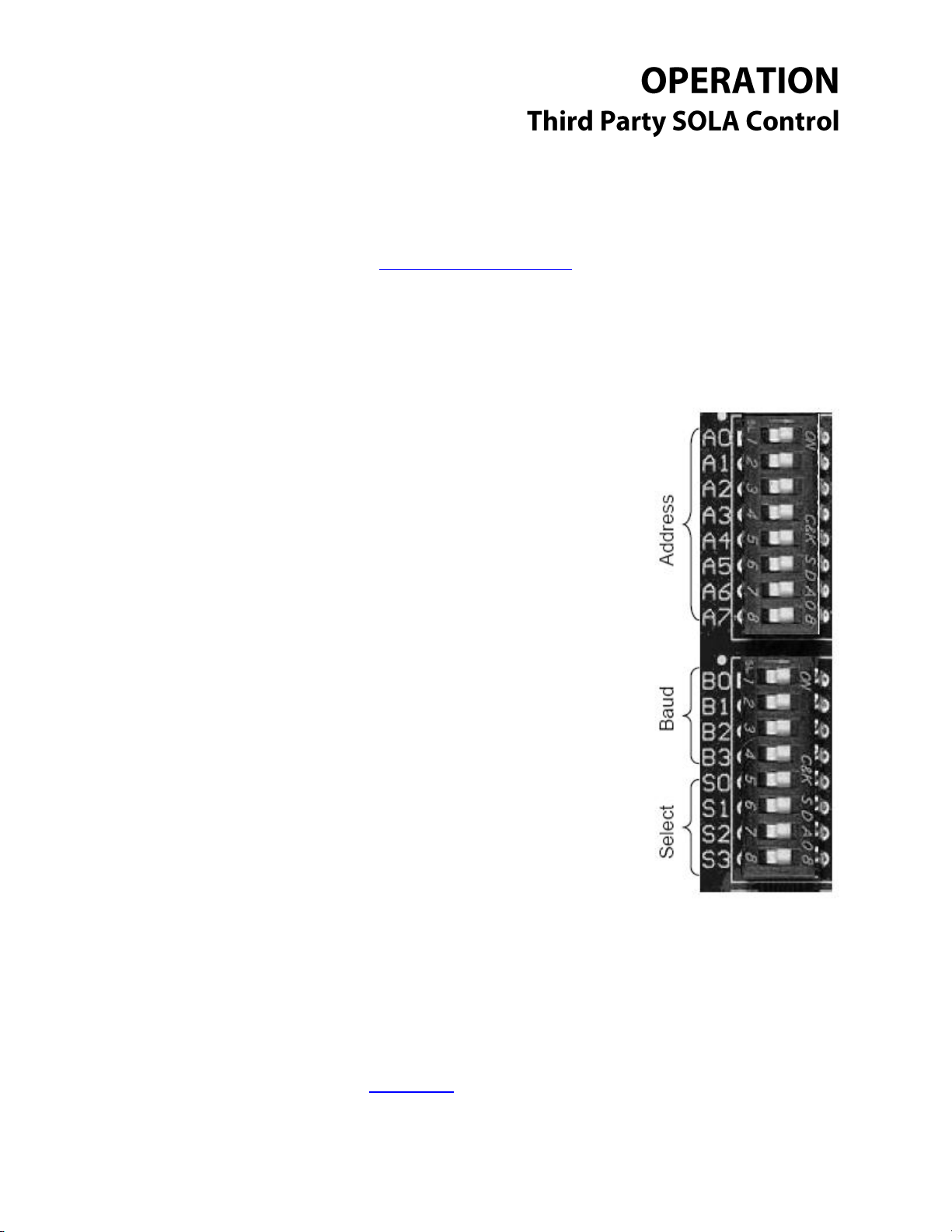
The bank of dipswitches (see top view), are used to configure the ProtoNode in the field. Available
configurations are node address, baud rate and configurations profile. See Node Address Setup
And Baud Rate Settings for more details.
Return to Table of Contents
_____________________________________________________________________________________
Questions? Call (315) 298-5121 or visit us online at www.fulton.com
©The Fulton Companies 2013
Supplement SOLA-IOM-2013-0220
Page 8
__________________________________________________________
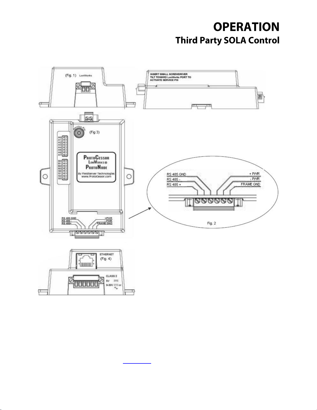
Lonworks Module: General and Connection Overview
The Lonworks ProtoNode provides three access ports (one server side, one client side and a service
port). The six pin connector (Fig. 2) provides RS 485 connection to the ModSync as well as provides the
24vdc power to the ProtoNode itself. The two pin connector (Fig. 1) provides Lonworks connection to
the Building Management System. The last available port is the Ethernet port (Fig. 4), which is used for
service situations such as downloading configuration files.
_____________________________________________________________________________________
Questions? Call (315) 298-5121 or visit us online at www.fulton.com
©The Fulton Companies 2013
Supplement SOLA-IOM-2013-0220
Page 9
__________________________________________________________
Dipswitches A0 – A7 are used to set the node
address of the ProtoNode device. See Addendum 1
for full address list and settings.
Dipswitches B0 – B3 are used to set the ProtoNode
baud rate. See Addendum 2 for full list and settings.
Dipswitches S0 – S3 are used to set which profile the
ProtoNode uses when it loads the config files it
requires to function. See Addendum 3 for full profile
list and settings.
The bank of dipswitches (see top view), are used to configure the ProtoNode in the field. Available
configurations are node address, baud rate and configurations profile.
Return to Table of Contents
Module Dipswitch Overview: All Modules
_____________________________________________________________________________________
Questions? Call (315) 298-5121 or visit us online at www.fulton.com
©The Fulton Companies 2013
Supplement SOLA-IOM-2013-0220
Page 10
__________________________________________________________
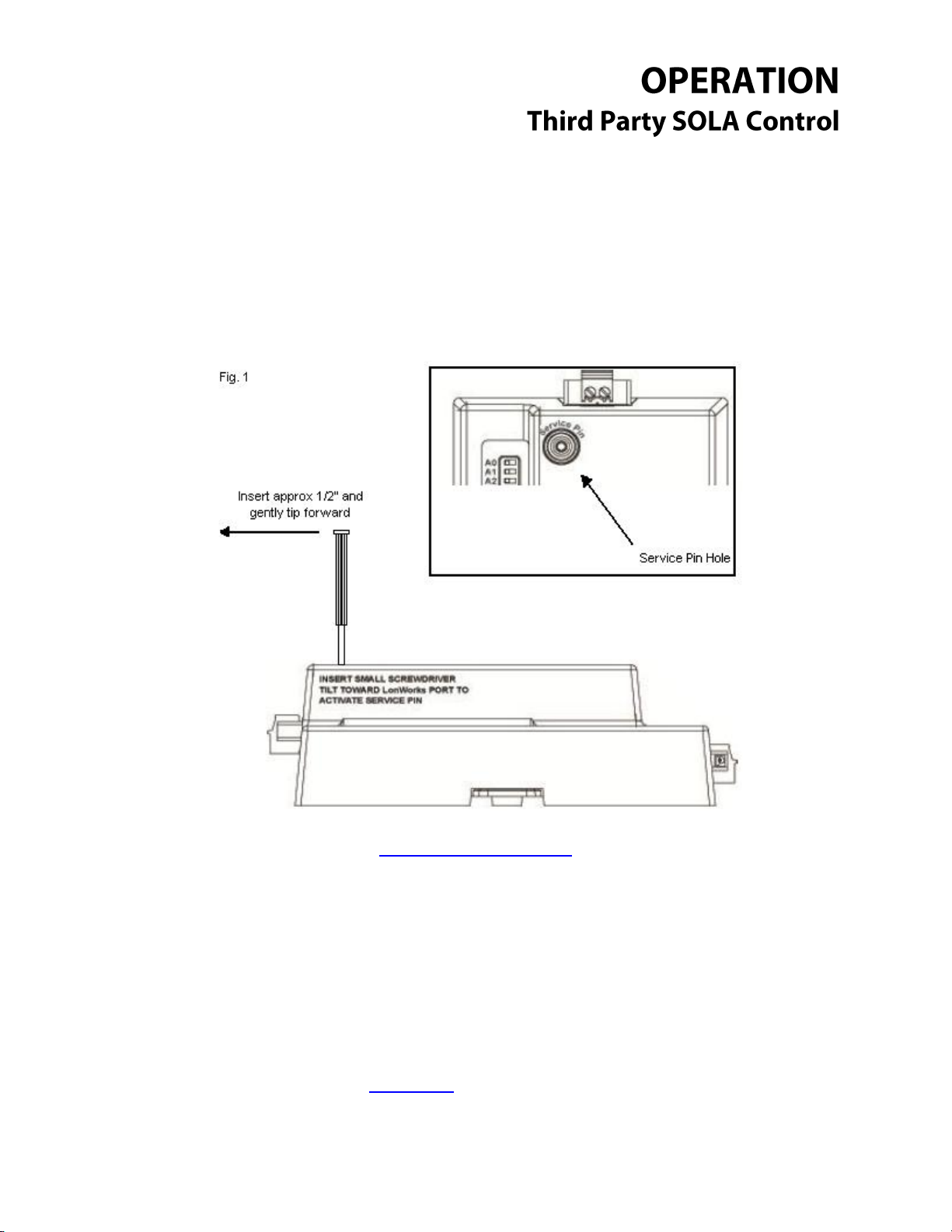
Module Service Pin: Lonworks Module Only
The service pin is used during the commissioning process on a Lonworks network. In order to use the
service pin on this module you will need a small screwdriver, small enough to fit into the service pin
hole. Put the screwdriver into the service pin hole and tilt gently forward towards the Lonworks 2 pin
connector. See Fig. 1.
Return to Table of Contents
_____________________________________________________________________________________
Questions? Call (315) 298-5121 or visit us online at www.fulton.com
©The Fulton Companies 2013
Supplement SOLA-IOM-2013-0220
Page 11

__________________________________________________________
Downloading New Configuration Files: All Modules
The ProtoNode modules come with all the standard configuration files already installed for use.
However, under certain circumstances configuration files may have to be updated in the field. Use
the following steps to update the configuration files for a module already in service in the field. The
steps are the same for all modules with the slight exception to the Lonworks module; see the
exceptions note at the end.
1. Once you have gone through all the proper channels to get the point mapping completed, you
will receive a ZIP file that contains several files. While the total amount of files in the ZIP will vary,
two files will remain constant:
a. Ruinet.exe
b. Profile.bat
These files can be run from any folder on your computer, so long as all files in the ZIP stay
together in the same folder. In most cases it is advantageous to extract the files to a single
folder on your desktop or another easy to locate place for easy access.
* Example folder containing the new configuration files.
_____________________________________________________________________________________
Questions? Call (315) 298-5121 or visit us online at www.fulton.com
©The Fulton Companies 2013
Supplement SOLA-IOM-2013-0220
Page 12

__________________________________________________________
2. Connect your computer to the ProtoNode via the Ethernet port, using a standard Cat5 cable.
Please keep the following points in mind when trying to connect to the ProtoNode in this
manner:
a. The ProtoNode must be powered and running during this process.
b. If your computer has both Ethernet and Wireless connections available you will have to
disable the wireless connection temporarily during this process. See Temporarily
Disabling the Wireless Connection for a basic tutorial on disabling your wireless connection.
c. You must set your Ethernet connection to a static IP address and subnet. See Setting the
Static IP Address for a basic tutorial on static IP or if you have trouble connecting.
Static IP Address: 192.168.1.101
Static Subnet Address: 255.255.255.0
* Please note: if you already have a static IP address loaded in your computer write
that information down so you can restore that IP when you are complete. *
d. Plug the Cat5 cable into the Ethernet port on the ProtoNode and then into your
computer’s Ethernet port. Connection will take some time to complete. If you’re using
Windows, you should receive a notification at the task bar when it’s complete.
3. Once you have successfully made a connection, double left click on the Profile.bat file and wait
for it to complete. A window that resembles this one will pop up; when it disappears the
download is nearly complete.
* Example window showing Profile.bat running.
4. After the window disappears, the ProtoNode will automatically restart itself to complete the
downloading process. This process can take several minutes, so now would be a good time to
_____________________________________________________________________________________
Questions? Call (315) 298-5121 or visit us online at www.fulton.com
©The Fulton Companies 2013
Supplement SOLA-IOM-2013-0220
Page 13

__________________________________________________________
grab a cup of coffee. Once the ProtoNode has restarted, the new configuration files will be
ready to use.
5. Disconnect your Ethernet cable, and don’t forget to re-enable your wireless if you shut it down.
If you already had a static IP address loaded on your computer, restore it now or you might have
trouble connecting to the internet later.
6. Lonworks Exception: After new configuration files have been loaded into the Lonworks module,
it will most likely have to be re-commissioned into the Lonworks Network.
Return to Table of Contents
Connection Help
Setting the Static IP Address
For most windows users following these steps will allow you to temporarily set the static IP address
for connection to the ProtoNode module:
1. Click the Start Menu and go to Control Panel.
2. Double Left Click on the Network Connections Icon.
3. Right Click on the Local Area Connection Icon and select Properties.
4. Highlight Internet Protocol (TCP/IP) and press the Properties Button.
5. Select “Use the following IP Address” option.
6. In the IP address box input 192.168.1.101
7. In the Subnet mask input 255.255.255.0
8. Leave the Default gateway blank.
9. Press the OK Button on the two properties windows.
To remove the static IP Address when finished, follow steps 1 through 4. At step 5 Select “Obtain IP
Address Automatically” instead.
To restore a previous static IP Address follow all steps 1 through 9, substituting your static IP
information at steps 6 and 7.
Return to Table of Contents
_____________________________________________________________________________________
Questions? Call (315) 298-5121 or visit us online at www.fulton.com
©The Fulton Companies 2013
Supplement SOLA-IOM-2013-0220
Page 14

__________________________________________________________
Temporarily Disabling the Wireless Connection
For most windows users, following these steps will allow you to temporarily disable your wireless
connection while connecting to the ProtoNode module:
1. Click the Start Menu and go to Control Panel.
2. Double Left Click on the Network Connections Icon.
3. Right Click on the Wireless Network Connections Icon and Select Disable.
To re-enable the wireless connection follow these steps:
1. Click the Start Menu and go to Control Panel.
2. Double Left Click on the Network Connections Icon.
3. Right Click on the Wireless Network Connections Icon and Select Enable.
4. This should automatically reconnect you with the first available wireless signal. In some cases it
may require step 5 to complete the task.
5. If the wireless still has not come back online, Right Click on the Wireless Network Icon and Select
Repair. Please make sure that there is a wireless signal available.
Please keep in mind that these steps were written with Windows users in mind, and that because each
computer system is different you might have to change some of these steps. When in doubt ask your
local network administrator or IT person for assistance.
Return to Table of Contents
Connection Troubleshooting
After following the connection guide, if you’re still having trouble connecting to the ProtoNode try the
following trouble shooting steps:
- Is the ProtoNode powered up? If not, check the wiring. Also check to ensure there is a solid
24vdc to the unit.
- Make sure all the connectors are secured on the ProtoNode including the 6 pin connector
and either the 3 pin or 2 pin connector, depending on whether you’re using the BACnet or
Lonworks module.
- Check the voltage between the customer connection terminal blocks (usually P2+/- in the
ModSync) and the outgoing voltage at the ProtoNode (either the 3 pin connector or 2 pin
depending on whether you’re using the BACnet or Lonworks module). While this voltage
may vary some, make sure that they are in the same average range. (For example, if you
_____________________________________________________________________________________
Questions? Call (315) 298-5121 or visit us online at www.fulton.com
©The Fulton Companies 2013
Supplement SOLA-IOM-2013-0220
Page 15

__________________________________________________________
A7
A6
A5
A4
A3
A2
A1
A0
Address
Off
Off
Off
Off
Off
Off
Off
Off
0
Off
Off
Off
Off
Off
Off
Off
On
1
Off
Off
Off
Off
Off
Off
On
Off
2
Off
Off
Off
Off
Off
Off
On
On
3
Off
Off
Off
Off
Off
On
Off
Off
4
Off
Off
Off
Off
Off
On
Off
On
5
Off
Off
Off
Off
Off
On
On
Off
6
Off
Off
Off
Off
Off
On
On
On
7
Off
Off
Off
Off
On
Off
Off
Off
8
Off
Off
Off
Off
On
Off
Off
On
9
Off
Off
Off
Off
On
Off
On
Off
10
Off
Off
Off
Off
On
Off
On
On
11
Off
Off
Off
Off
On
On
Off
Off
12
Off
Off
Off
Off
On
On
Off
On
13
have 1.4v at the 3 pin connector you should have something close to that at the ModSync
terminal blocks.)
- Verify that your computer has connected to the ProtoNode. By Right Clicking on the Local
Area Connection and Selecting “Status” you can see whether or not your computer has
connected to the ProtoNode. If not double check your settings (step 2 on Page 8.)
- Verify all dipswitch settings on the ProtoNode module. Use Addendums 1, 2 and 3 as a
guide. *If any dipswitches are changed you will have to restart the ProtoNode before they
take effect.
- If you have connected, but all information to the BMS has a value of zero, check the BMS
settings on the BMS screen at the ModSync. Standard settings are Node 2, Baud 19200,
RS485. *If you change any of those settings at the ModSync make sure you press the
“ModSync Reset” button to allow those changes to take place. You will know the ModSync is
resetting when the screen goes blank for a few seconds.
Return to Table of Contents
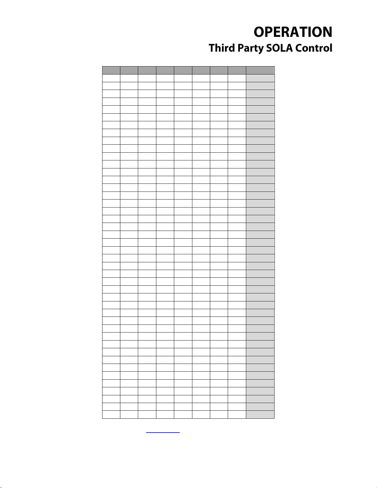
Node Address Setup
Please note that any changes made to ANY of the dipswitches require the ProtoNode to be restarted.
For this reason it is suggested that the all the dipswitches be configured BEFORE powering up the
ProtoNode. Restarting the ProtoNode on a Lonworks network may require the ProtoNode to be recommissioned into the network.
_____________________________________________________________________________________
Questions? Call (315) 298-5121 or visit us online at www.fulton.com
©The Fulton Companies 2013
Supplement SOLA-IOM-2013-0220
Page 16

__________________________________________________________
A7
A6
A5
A4
A3
A2
A1
A0
Address
Off
Off
Off
Off
On
On
On
Off
14
Off
Off
Off
Off
On
On
On
On
15
Off
Off
Off
On
Off
Off
Off
Off
16
Off
Off
Off
On
Off
Off
Off
On
17
Off
Off
Off
On
Off
Off
On
Off
18
Off
Off
Off
On
Off
Off
On
On
19
Off
Off
Off
On
Off
On
Off
Off
20
Off
Off
Off
On
Off
On
Off
On
21
Off
Off
Off
On
Off
On
On
Off
22
Off
Off
Off
On
Off
On
On
On
23
Off
Off
Off
On
On
Off
Off
Off
24
Off
Off
Off
On
On
Off
Off
On
25
Off
Off
Off
On
On
Off
On
Off
26
Off
Off
Off
On
On
Off
On
On
27
Off
Off
Off
On
On
On
Off
Off
28
Off
Off
Off
On
On
On
Off
On
29
Off
Off
Off
On
On
On
On
Off
30
Off
Off
Off
On
On
On
On
On
31
Off
Off
On
Off
Off
Off
Off
Off
32
Off
Off
On
Off
Off
Off
Off
On
33
Off
Off
On
Off
Off
Off
On
Off
34
Off
Off
On
Off
Off
Off
On
On
35
Off
Off
On
Off
Off
On
Off
Off
36
Off
Off
On
Off
Off
On
Off
On
37
Off
Off
On
Off
Off
On
On
Off
38
Off
Off
On
Off
Off
On
On
On
39
Off
Off
On
Off
On
Off
Off
Off
40
Off
Off
On
Off
On
Off
Off
On
41
Off
Off
On
Off
On
Off
On
Off
42
Off
Off
On
Off
On
Off
On
On
43
Off
Off
On
Off
On
On
Off
Off
44
Off
Off
On
Off
On
On
Off
On
45
Off
Off
On
Off
On
On
On
Off
46
Off
Off
On
Off
On
On
On
On
47
Off
Off
On
On
Off
Off
Off
Off
48
Off
Off
On
On
Off
Off
Off
On
49
Off
Off
On
On
Off
Off
On
Off
50
Off
Off
On
On
Off
Off
On
On
51
Off
Off
On
On
Off
On
Off
Off
52
Off
Off
On
On
Off
On
Off
On
53
Off
Off
On
On
Off
On
On
Off
54
Off
Off
On
On
Off
On
On
On
55
Off
Off
On
On
On
Off
Off
Off
56
Off
Off
On
On
On
Off
Off
On
57
_____________________________________________________________________________________
Questions? Call (315) 298-5121 or visit us online at www.fulton.com
©The Fulton Companies 2013
Supplement SOLA-IOM-2013-0220
Page 17

__________________________________________________________
A7
A6
A5
A4
A3
A2
A1
A0
Address
Off
Off
On
On
On
Off
On
Off
58
Off
Off
On
On
On
Off
On
On
59
Off
Off
On
On
On
On
Off
Off
60
Off
Off
On
On
On
On
Off
On
61
Off
Off
On
On
On
On
On
Off
62
Off
Off
On
On
On
On
On
On
63
Off
On
Off
Off
Off
Off
Off
Off
64
Off
On
Off
Off
Off
Off
Off
On
65
Off
On
Off
Off
Off
Off
On
Off
66
Off
On
Off
Off
Off
Off
On
On
67
Off
On
Off
Off
Off
On
Off
Off
68
Off
On
Off
Off
Off
On
Off
On
69
Off
On
Off
Off
Off
On
On
Off
70
Off
On
Off
Off
Off
On
On
On
71
Off
On
Off
Off
On
Off
Off
Off
72
Off
On
Off
Off
On
Off
Off
On
73
Off
On
Off
Off
On
Off
On
Off
74
Off
On
Off
Off
On
Off
On
On
75
Off
On
Off
Off
On
On
Off
Off
76
Off
On
Off
Off
On
On
Off
On
77
Off
On
Off
Off
On
On
On
Off
78
Off
On
Off
Off
On
On
On
On
79
Off
On
Off
On
Off
Off
Off
Off
80
Off
On
Off
On
Off
Off
Off
On
81
Off
On
Off
On
Off
Off
On
Off
82
Off
On
Off
On
Off
Off
On
On
83
Off
On
Off
On
Off
On
Off
Off
84
Off
On
Off
On
Off
On
Off
On
85
Off
On
Off
On
Off
On
On
Off
86
Off
On
Off
On
Off
On
On
On
87
Off
On
Off
On
On
Off
Off
Off
88
Off
On
Off
On
On
Off
Off
On
89
Off
On
Off
On
On
Off
On
Off
90
Off
On
Off
On
On
Off
On
On
91
Off
On
Off
On
On
On
Off
Off
92
Off
On
Off
On
On
On
Off
On
93
Off
On
Off
On
On
On
On
Off
94
Off
On
Off
On
On
On
On
On
95
Off
On
On
Off
Off
Off
Off
Off
96
Off
On
On
Off
Off
Off
Off
On
97
Off
On
On
Off
Off
Off
On
Off
98
Off
On
On
Off
Off
Off
On
On
99
Off
On
On
Off
Off
On
Off
Off
100
Off
On
On
Off
Off
On
Off
On
101
_____________________________________________________________________________________
Questions? Call (315) 298-5121 or visit us online at www.fulton.com
©The Fulton Companies 2013
Supplement SOLA-IOM-2013-0220
Page 18

__________________________________________________________
A7
A6
A5
A4
A3
A2
A1
A0
Address
Off
On
On
Off
Off
On
On
Off
102
Off
On
On
Off
Off
On
On
On
103
Off
On
On
Off
On
Off
Off
Off
104
Off
On
On
Off
On
Off
Off
On
105
Off
On
On
Off
On
Off
On
Off
106
Off
On
On
Off
On
Off
On
On
107
Off
On
On
Off
On
On
Off
Off
108
Off
On
On
Off
On
On
Off
On
109
Off
On
On
Off
On
On
On
Off
110
Off
On
On
Off
On
On
On
On
111
Off
On
On
On
Off
Off
Off
Off
112
Off
On
On
On
Off
Off
Off
On
113
Off
On
On
On
Off
Off
On
Off
114
Off
On
On
On
Off
Off
On
On
115
Off
On
On
On
Off
On
Off
Off
116
Off
On
On
On
Off
On
Off
On
117
Off
On
On
On
Off
On
On
Off
118
Off
On
On
On
Off
On
On
On
119
Off
On
On
On
On
Off
Off
Off
120
Off
On
On
On
On
Off
Off
On
121
Off
On
On
On
On
Off
On
Off
122
Off
On
On
On
On
Off
On
On
123
Off
On
On
On
On
On
Off
Off
124
Off
On
On
On
On
On
Off
On
125
Off
On
On
On
On
On
On
Off
126
Off
On
On
On
On
On
On
On
127
On
Off
Off
Off
Off
Off
Off
Off
128
On
Off
Off
Off
Off
Off
Off
On
129
On
Off
Off
Off
Off
Off
On
Off
130
On
Off
Off
Off
Off
Off
On
On
131
On
Off
Off
Off
Off
On
Off
Off
132
On
Off
Off
Off
Off
On
Off
On
133
On
Off
Off
Off
Off
On
On
Off
134
On
Off
Off
Off
Off
On
On
On
135
On
Off
Off
Off
On
Off
Off
Off
136
On
Off
Off
Off
On
Off
Off
On
137
On
Off
Off
Off
On
Off
On
Off
138
On
Off
Off
Off
On
Off
On
On
139
On
Off
Off
Off
On
On
Off
Off
140
On
Off
Off
Off
On
On
Off
On
141
On
Off
Off
Off
On
On
On
Off
142
On
Off
Off
Off
On
On
On
On
143
On
Off
Off
On
Off
Off
Off
Off
144
On
Off
Off
On
Off
Off
Off
On
145
_____________________________________________________________________________________
Questions? Call (315) 298-5121 or visit us online at www.fulton.com
©The Fulton Companies 2013
Supplement SOLA-IOM-2013-0220
Page 19
__________________________________________________________
A7
A6
A5
A4
A3
A2
A1
A0
Address
On
Off
Off
On
Off
Off
On
Off
146
On
Off
Off
On
Off
Off
On
On
147
On
Off
Off
On
Off
On
Off
Off
148
On
Off
Off
On
Off
On
Off
On
149
On
Off
Off
On
Off
On
On
Off
150
On
Off
Off
On
Off
On
On
On
151
On
Off
Off
On
On
Off
Off
Off
152
On
Off
Off
On
On
Off
Off
On
153
On
Off
Off
On
On
Off
On
Off
154
On
Off
Off
On
On
Off
On
On
155
On
Off
Off
On
On
On
Off
Off
156
On
Off
Off
On
On
On
Off
On
157
On
Off
Off
On
On
On
On
Off
158
On
Off
Off
On
On
On
On
On
159
On
Off
On
Off
Off
Off
Off
Off
160
On
Off
On
Off
Off
Off
Off
On
161
On
Off
On
Off
Off
Off
On
Off
162
On
Off
On
Off
Off
Off
On
On
163
On
Off
On
Off
Off
On
Off
Off
164
On
Off
On
Off
Off
On
Off
On
165
On
Off
On
Off
Off
On
On
Off
166
On
Off
On
Off
Off
On
On
On
167
On
Off
On
Off
On
Off
Off
Off
168
On
Off
On
Off
On
Off
Off
On
169
On
Off
On
Off
On
Off
On
Off
170
On
Off
On
Off
On
Off
On
On
171
On
Off
On
Off
On
On
Off
Off
172
On
Off
On
Off
On
On
Off
On
173
On
Off
On
Off
On
On
On
Off
174
On
Off
On
Off
On
On
On
On
175
On
Off
On
On
Off
Off
Off
Off
176
On
Off
On
On
Off
Off
Off
On
177
On
Off
On
On
Off
Off
On
Off
178
On
Off
On
On
Off
Off
On
On
179
On
Off
On
On
Off
On
Off
Off
180
On
Off
On
On
Off
On
Off
On
181
On
Off
On
On
Off
On
On
Off
182
On
Off
On
On
Off
On
On
On
183
On
Off
On
On
On
Off
Off
Off
184
On
Off
On
On
On
Off
Off
On
185
On
Off
On
On
On
Off
On
Off
186
On
Off
On
On
On
Off
On
On
187
On
Off
On
On
On
On
Off
Off
188
On
Off
On
On
On
On
Off
On
189
_____________________________________________________________________________________
Questions? Call (315) 298-5121 or visit us online at www.fulton.com
©The Fulton Companies 2013
Supplement SOLA-IOM-2013-0220
Page 20

__________________________________________________________
A7
A6
A5
A4
A3
A2
A1
A0
Address
On
Off
On
On
On
On
On
Off
190
On
Off
On
On
On
On
On
On
191
On
On
Off
Off
Off
Off
Off
Off
192
On
On
Off
Off
Off
Off
Off
On
193
On
On
Off
Off
Off
Off
On
Off
194
On
On
Off
Off
Off
Off
On
On
195
On
On
Off
Off
Off
On
Off
Off
196
On
On
Off
Off
Off
On
Off
On
197
On
On
Off
Off
Off
On
On
Off
198
On
On
Off
Off
Off
On
On
On
199
On
On
Off
Off
On
Off
Off
Off
200
On
On
Off
Off
On
Off
Off
On
201
On
On
Off
Off
On
Off
On
Off
202
On
On
Off
Off
On
Off
On
On
203
On
On
Off
Off
On
On
Off
Off
204
On
On
Off
Off
On
On
Off
On
205
On
On
Off
Off
On
On
On
Off
206
On
On
Off
Off
On
On
On
On
207
On
On
Off
On
Off
Off
Off
Off
208
On
On
Off
On
Off
Off
Off
On
209
On
On
Off
On
Off
Off
On
Off
210
On
On
Off
On
Off
Off
On
On
211
On
On
Off
On
Off
On
Off
Off
212
On
On
Off
On
Off
On
Off
On
213
On
On
Off
On
Off
On
On
Off
214
On
On
Off
On
Off
On
On
On
215
On
On
Off
On
On
Off
Off
Off
216
On
On
Off
On
On
Off
Off
On
217
On
On
Off
On
On
Off
On
Off
218
On
On
Off
On
On
Off
On
On
219
On
On
Off
On
On
On
Off
Off
220
On
On
Off
On
On
On
Off
On
221
On
On
Off
On
On
On
On
Off
222
On
On
Off
On
On
On
On
On
223
On
On
On
Off
Off
Off
Off
Off
224
On
On
On
Off
Off
Off
Off
On
225
On
On
On
Off
Off
Off
On
Off
226
On
On
On
Off
Off
Off
On
On
227
On
On
On
Off
Off
On
Off
Off
228
On
On
On
Off
Off
On
Off
On
229
On
On
On
Off
Off
On
On
Off
230
On
On
On
Off
Off
On
On
On
231
On
On
On
Off
On
Off
Off
Off
232
On
On
On
Off
On
Off
Off
On
233
_____________________________________________________________________________________
Questions? Call (315) 298-5121 or visit us online at www.fulton.com
©The Fulton Companies 2013
Supplement SOLA-IOM-2013-0220
Page 21

__________________________________________________________
A7
A6
A5
A4
A3
A2
A1
A0
Address
On
On
On
Off
On
Off
On
Off
234
On
On
On
Off
On
Off
On
On
235
On
On
On
Off
On
On
Off
Off
236
On
On
On
Off
On
On
Off
On
237
On
On
On
Off
On
On
On
Off
238
On
On
On
Off
On
On
On
On
239
On
On
On
On
Off
Off
Off
Off
240
On
On
On
On
Off
Off
Off
On
241
On
On
On
On
Off
Off
On
Off
242
On
On
On
On
Off
Off
On
On
243
On
On
On
On
Off
On
Off
Off
244
On
On
On
On
Off
On
Off
On
245
On
On
On
On
Off
On
On
Off
246
On
On
On
On
Off
On
On
On
247
On
On
On
On
On
Off
Off
Off
248
On
On
On
On
On
Off
Off
On
249
On
On
On
On
On
Off
On
Off
250
On
On
On
On
On
Off
On
On
251
On
On
On
On
On
On
Off
Off
252
On
On
On
On
On
On
Off
On
253
On
On
On
On
On
On
On
Off
254
On
On
On
On
On
On
On
On
255
Return to Table of Contents
Baud Rate Settings
Please note that any changes made to ANY of the dipswitches require the ProtoNode to be
restarted. For this reason it is suggested that the all the dipswitches be configured BEFORE powering
up the ProtoNode. Restarting the ProtoNode on a Lonworks network may require the ProtoNode to
be re-commissioned into the network.
_____________________________________________________________________________________
Questions? Call (315) 298-5121 or visit us online at www.fulton.com
©The Fulton Companies 2013
Supplement SOLA-IOM-2013-0220
Page 22

__________________________________________________________
2
Auto baud rates are only supported on BACnet MSTP
Return to Table of Contents
Modbus to Bacnet Pre-Loaded Gateway Points
Sola LEAD/LAG Bacnet points as of 12/5/12 V1.00
[Read points] (* points exclusive to lead lag)
1. *Lead lag master status [LLMstrStat] 0160
a. 0=Unknown
_____________________________________________________________________________________
Questions? Call (315) 298-5121 or visit us online at www.fulton.com
©The Fulton Companies 2013
Supplement SOLA-IOM-2013-0220
Page 23

__________________________________________________________
b. 1=Disabled
c. 2=Normal
d. 3=Suspended
2. *Lead lag master heat demand [LLMstrHeatD] 0163
a. 0=off
b. 1=on
3. *Master firing rate [MstrFR] 0802
a. 0-100%
4. *Slave burner demand [LLSlvDmd] 0164
a. 0=off
b. 1=on
5. *Slave 1 state [LLSlv1Stat] 0770
a. 0=unknown
b. 1=available
c. 2=add stage
d. 3=suspend stage
e. 4=firing
f. 5=on leave
g. 6=Disabled
h. 7=recovering
_____________________________________________________________________________________
Questions? Call (315) 298-5121 or visit us online at www.fulton.com
©The Fulton Companies 2013
Supplement SOLA-IOM-2013-0220
Page 24

__________________________________________________________
6. *Slave 1 stage order [LLSlv1_Ordr] 0771
a. Relative order that slave 1 has been added to fire
b. 0=Not been staged
7. *Slave 1 firing rate [LLSlv1FR] 0772
a. Current firing rate (0-100%) of slave 1
8. *Slave 2 state [LLSlv2Stat] 0774
a. 0=unknown
b. 1=available
c. 2=add stage
d. 3=suspend stage
e. 4=firing
f. 5=on leave
g. 6=Disabled
h. 7=recovering
9. *Slave 2 stage order [LLSlv2Ordr] 0775
a. Relative order that slave 2 has been added to fire
b. 0=Not been staged
10. *Slave 2 firing rate [LLSlv2FR] 0776
a. Current firing rate (0-100%) of slave 2
_____________________________________________________________________________________
Questions? Call (315) 298-5121 or visit us online at www.fulton.com
©The Fulton Companies 2013
Supplement SOLA-IOM-2013-0220
Page 25

__________________________________________________________
11. *Slave 3 state [LLSlv3Stat] 0778
a. 0=unknown
b. 1=available
c. 2=add stage
d. 3=suspend stage
e. 4=firing
f. 5=on leave
g. 6=Disabled
h. 7=recovering
12. *Slave 3 stage order [LLSlv3Ordr] 0779
a. Relative order that slave 3 has been added to fire
b. 0=Not been staged
13. *Slave 3 firing rate [LLSlv3FR] 0780
a. Current firing rate (0-100%) of slave 3
14. *Slave 4 state [LLSlv4Stat] 0782
a. 0=unknown
b. 1=available
c. 2=add stage
d. 3=suspend stage
e. 4=firing
_____________________________________________________________________________________
Questions? Call (315) 298-5121 or visit us online at www.fulton.com
©The Fulton Companies 2013
Supplement SOLA-IOM-2013-0220
Page 26

__________________________________________________________
f. 5=on leave
g. 6=Disabled
h. 7=recovering
15. *Slave 4 stage order [LLSlv4Ordr] 0783
a. Relative order that slave 4 has been added to fire
b. 0=Not been staged
16. *Slave 4 firing rate [LLSlv4FR] 0784
a. Current firing rate (0-100%) of slave 4
17. *Slave 5 state [LLSlv5Stat] 0786
a. 0=unknown
b. 1=available
c. 2=add stage
d. 3=suspend stage
e. 4=firing
f. 5=on leave
g. 6=Disabled
h. 7=recovering
18. *Slave 5 stage order [LLSlv5Ordr] 0787
a. Relative order that slave 5 has been added to fire
b. 0=Not been staged
_____________________________________________________________________________________
Questions? Call (315) 298-5121 or visit us online at www.fulton.com
©The Fulton Companies 2013
Supplement SOLA-IOM-2013-0220
Page 27

__________________________________________________________
19. *Slave 5 firing rate [LLSlv5FR] 0788
a. Current firing rate (0-100%) of slave 5
20. *Slave 6 state [LLSlv6Stat] 0790
a. 0=unknown
b. 1=available
c. 2=add stage
d. 3=suspend stage
e. 4=firing
f. 5=on leave
g. 6=Disabled
h. 7=recovering
21. *Slave 6 stage order [LLSlv6Ordr] 0791
a. Relative order that slave 6 has been added to fire
b. 0=Not been staged
22. *Slave 6 firing rate [LLSlv6FR] 0792
a. Current firing rate (0-100%) of slave 6
23. *Slave 7 state [LLSlv7Stat] 0794
a. 0=unknown
b. 1=available
_____________________________________________________________________________________
Questions? Call (315) 298-5121 or visit us online at www.fulton.com
©The Fulton Companies 2013
Supplement SOLA-IOM-2013-0220
Page 28

__________________________________________________________
c. 2=add stage
d. 3=suspend stage
e. 4=firing
f. 5=on leave
g. 6=Disabled
h. 7=recovering
24. *Slave 7 stage order [LLSlv7Ordr] 0795
a. Relative order that slave 7 has been added to fire
b. 0=Not been staged
25. *Slave 7 firing rate [LL_SLAVE_7_FR] 0796
a. Current firing rate (0-100%) of slave 7
26. Slave 8 state [LLSlv8Stat] 0798
a. 0=unknown
b. 1=available
c. 2=add stage
d. 3=suspend stage
e. 4=firing
f. 5=on leave
g. 6=Disabled
h. 7=recovering
_____________________________________________________________________________________
Questions? Call (315) 298-5121 or visit us online at www.fulton.com
©The Fulton Companies 2013
Supplement SOLA-IOM-2013-0220
Page 29

__________________________________________________________
27. *Slave 8 stage order [LLSlv8Ordr] 0799
a. Relative order that slave 8 has been added to fire
b. 0=Not been staged
28. *Slave 8 firing rate [LLSlv1FR] 0800
a. Current firing rate (0-100%) of slave 8
29. *Active lead lag setpoint [LLSetpntF] 0018
a. -40˚C - 130˚C (will display as -40˚F - 266˚F)
30. *Active lead lag operating point [LLOprtingF] 0027
a. -40˚C - 130˚C (will display as -40˚F - 266˚F)
31. Inlet Sensor State [InletState] 0049
a. 0=none
b. 1=Normal
c. 2=open
d. 3=shorted
e. 4=outside high range
f. 5=outside low range
g. 6=not reliable
32. Inlet (S1) sensor [InletTempF] 0011
a. -40˚C - 130˚C (will display as -40˚F - 266˚F)
_____________________________________________________________________________________
Questions? Call (315) 298-5121 or visit us online at www.fulton.com
©The Fulton Companies 2013
Supplement SOLA-IOM-2013-0220
Page 30

__________________________________________________________
33. Outlet limit sensor [OutletState1] 0048
a. 0=none
b. 1=Normal
c. 2=Open
d. 3=shorted
e. 4=Outside high range
f. 5=Outside low range
g. 6=Not reliable
34. Outlet Operation sensor [OutletState2] 0046
a. 0=none
b. 1=Normal
c. 2=Open
d. 3=shorted
e. 4=Outside high range
f. 5=Outside low range
g. 6=Not reliable
35. Outlet (S3S4) or Outlet limit (S3) sensor [OutletTempF] 0007
a. -40˚C - 130˚C (will display as -40˚F - 266˚F)
36. S5 Sensor State [HeaderState] 0052
a. 0=none
_____________________________________________________________________________________
Questions? Call (315) 298-5121 or visit us online at www.fulton.com
©The Fulton Companies 2013
Supplement SOLA-IOM-2013-0220
Page 31

__________________________________________________________
b. 1=normal
c. 2=open
d. 3=shorted
e. 4=outside high range
f. 5=outside low range
g. 6=not reliable
37. S5 sensor [HeadTemp] 0013
a. -40˚C - 130˚C (will display as -40˚F - 266˚F)
38. Firing rate [FireRate] 0008
a. 0-100%
39. Outdoor sensor state [OutdrState] 0171
a. 0=none
b. 1=Normal
c. 2=Open
d. 3=shorted
e. 4=Outside high range
f. 5=Outside low range
g. 6=Not reliable
40. Outdoor Temp [OutDoorF] 0170
a. -40˚C - 130˚C (will display as -40˚F - 266˚F)
_____________________________________________________________________________________
Questions? Call (315) 298-5121 or visit us online at www.fulton.com
©The Fulton Companies 2013
Supplement SOLA-IOM-2013-0220
Page 32

__________________________________________________________
41. Boiler pump status [BlrPmpStats] 0108
a. Refer to Sola manual
42. Annunciator I/O [Annunciator] 0003
a. 15-8=reserved
b. 7=annunciator 8
c. 6=annunciator 7
d. 5=annunciator 6
e. 4=annunciator 5
f. 3=annunciator 4
g. 2=annunciator 3
h. 1=annunciator 2
i. 0=annunciator 1
i. Example 194 (decimal) = 11000010 binary
1. Annunciators 2,7&8 are proved.
43. Alarm reason [AlrmReason] 0035
a. 0=none
b. 1=Lockout (see manual)
c. 2= alert (se manual)
d. 3=other
44. Lockout code [LckOutCode] 0034
_____________________________________________________________________________________
Questions? Call (315) 298-5121 or visit us online at www.fulton.com
©The Fulton Companies 2013
Supplement SOLA-IOM-2013-0220
Page 33

__________________________________________________________
a. 0=no lockout
b. 1-4096 (see manual)
45. Flame signal [Flame_Sig] 0010
a. 0.01V or 0.01A precision (0.00-50.00v)
46. Active CH setpoint [CHSetpoint] 0016
a. -40˚C - 130˚C (will display as -40˚F - 266˚F)
47. Burner control status [BrnrCntrlSt] 0032
a. 0=disabled
b. 1=locked out
c. 2=reserved
d. 3=reserved
e. 4=anti-short cycle
f. 5=unconfigured safety data
g. 6-33=reserved
h. 34=standby hold
i. 35=standby delay
j. 36-47=reserved
k. 48=normal standby
l. 49=preparing
m. 50=ignition
n. 51=firing
_____________________________________________________________________________________
Questions? Call (315) 298-5121 or visit us online at www.fulton.com
©The Fulton Companies 2013
Supplement SOLA-IOM-2013-0220
Page 34

__________________________________________________________
o. 52=postpurge
p. 53-65535=reserved
48. CH status [CHStat] 0064
a. 0=unknown
b. 1=disabled
c. 2=normal
d. 3=suspended
49. CH setpoint source [CHStpntSrc] 0065
a. 0=unknown
b. 1=normal setpoint
c. 2=TOD setpoint
d. 3=Outdoor reset
e. 4=Remote control
f. 7=Outdoor reset time of day
g. 9=Outdoor boost
50. Demand Source [DemandSrc] 0006
a. 0=unknown
b. 1=no source demand
c. 2=CH
d. 3=DHW
e. 4=Lead Lag Slave
_____________________________________________________________________________________
Questions? Call (315) 298-5121 or visit us online at www.fulton.com
©The Fulton Companies 2013
Supplement SOLA-IOM-2013-0220
Page 35

__________________________________________________________
f. 5=Lead Lag Master
g. 6=CH frost protection
h. 7=DHW frost protection
i. 8=No demand due to burner switch
j. 9=DHW Storage
k. 10=Reserved
l. 11=warm weather shutdown
51. CH heat demand [CHHeatDmnd] 0066
a. 0=off
b. 1=on
52. CH burner demand [CHBrnrDmnd] 0067
a. 0=off
b. 1=on
[write points]
53. CH setpoint [CHSetpointF] 0211
a. -40˚C - 130˚C (input -40˚F - 266˚F)
54. *Lead lag setpoint [LLSetpntF] 0546
a. -40˚C - 130˚C (input -40˚F - 266˚F)
55. CH enable [CHENABLE] 0208
a. 0=disable central heat
_____________________________________________________________________________________
Questions? Call (315) 298-5121 or visit us online at www.fulton.com
©The Fulton Companies 2013
Supplement SOLA-IOM-2013-0220
Page 36

__________________________________________________________
b. 1=enable central heat
56. *Lead lag CH demand switch [LLDEMAND] 0556
a. 0=disable CH loop
b. 1=stat
c. 2=reserved
d. 3=EnviraCOM remote STAT
e. 4=Modbus STAT
f. 5=Reserved
g. 6=STAT terminal or EnvironCOM remote STAT
57. *Lead Lag outdoor reset enable [LLOutdrRst] 0548
a. 0=disable
b. 1=enable
58. Central Heat Outdoor Enable [CHOutdrRst] 0215
a. 0=disable
b. 1=enable
59. CH priority vs. Lead Lag [CHvsLL] 0582
a. 0=lead lag > central heat
b. 1=central heat > lead lag
Return to Table of Contents
_____________________________________________________________________________________
Questions? Call (315) 298-5121 or visit us online at www.fulton.com
©The Fulton Companies 2013
Supplement SOLA-IOM-2013-0220
 Loading...