

Page 1
INSTALLATION AND
OPERATION MANUAL
Caliber
High E ciency Hydronic Boilers
300,000 - 850,000 BTU/HR
Serial/ National
Board Number
Model
Fulton Order
Sold To
Job Name
Date
CAL-IOM-2014-0129
Page 2

Page 3

CAL-IOM-2014-0129 TABLE OF CONTENTS
Introduction 1-1
Overview .............................................................................................................. 1-2
Warnings & Cautions ............................................................................................ 1-2
Disclaimers and Local Codes ................................................................................ 1-2
Installation 2-1
Product Overview ................................................................................................. 2-2
Placement & Rigging ........................................................................................... 2-3
Clearances and Serviceability .............................................................................. 2-3
Install Boiler Trim ................................................................................................. 2-6
Install Water Piping .............................................................................................. 2-6
LOW WATER C UT OFF ...................................................................................................................2 7
Meet Water Chemistry Requirements .................................................................. 2-7
PREVENT FREEZING ...................................................................................................................2 11
PREVENT OXYGEN CONTAMINATION ........................................................................................ 211
ELIMINATE SYSTEM AIR ............................................................................................................212
Fill the Boiler With Water ................................................................................... 2-12
Install Gas Piping ................................................................................................ 2-13
Venting ............................................................................................................... 2-15
Combustion Air Intake ....................................................................................... 2-15
COMBUSTION AIR SUPPLY FROM THE BOILER ROOM ..............................................................215
COMBUSTION AIR PIPED FROM OUTSIDE BUILDING WITHOUT SEALED COMBUSTION ........216
AIR PIPED FROM OUTSIDE BOILER ROOM ................................................................................ 216
Exhaust Venting ................................................................................................. 2-16
STANDARD VENTING CONFIGURATION, CATEGORY IV .............................................................216
SIZING AIR INTAKE AND EXHAUST PIPING ...............................................................................217
COMMON AIR INTAKE AND EXHAUST VENTING OF MULTIPLE BOILERS ................................. 218
INTAKE DUCT SIZING .................................................................................................................219
Condensate Drain Piping .................................................................................... 2-20
Venting Terminations ......................................................................................... 2-20
WALL THIMBLE INSTALLATION .................................................................................................221
VENT TERMINATION ..................................................................................................................222
Electrical Connections ....................................................................................... 2-24
Test of High Back Pressure Switch ........................................................................ 3-4
Normal Operation of the Boiler ............................................................................ 3-4
CHANGING THE OPERATING SET POINT .....................................................................................35
SETTING COMBUSTION ................................................................................................................ 35
Shut Down Procedures ......................................................................................... 3-7
NORMAL SHUT OFF PROCEDURES .............................................................................................3 7
EMERGENCY SHUT OFF PROCEDURES .......................................................................................38
SHUTTING THE BOILER DOWN FOR AN EXTENDED PERIOD OF TIME ........................................38
STARTING BOILER AFTER PROLONGED SHUTDOWN ..................................................................3 8
SOLA Control Features .......................................................................................... 3-9
VIEWING THE FLAME SIGNAL .................................................................................................... 39
CYCLE AND RUN HOURS MONITORING .......................................................................................39
BOILER NAMING ..........................................................................................................................39
DELTA T LIMIT .............................................................................................................................310
STACK LIMIT ...............................................................................................................................310
LEAD/LAG CONFIGURATION .....................................................................................................3 10
Maintenance 4-1
General ................................................................................................................. 4-2
Daily Maintenance and Inspection Schedule ...................................................... 4-2
Weekly Maintenance and Inspection Schedule .................................................. 4-2
Monthly Maintenance and Inspection Schedule ................................................. 4-2
Procedure for Cleaning the Air Inlet Filter .......................................................... 4-3
Relief Valve Testing ............................................................................................... 4-3
Annual Maintenance and Inspection Schedule ................................................... 4-3
EXAMINE THE VENTING SYSTEM ................................................................................................44
Procedure for Removing/Cleaning The Burner .................................................... 4-4
Procedure for Cleaning Heat Exchanger ............................................................... 4-5
After All Repairs and Maintenance ...................................................................... 4-5
Troubleshooting ................................................................................................... 4-6
Warranty & Parts 5-1
Parts ..................................................................................................................... 5-2
Standard Warranty for Fulton Caliber Hydronic Boilers ....................................... 5-3
Operation 3-1
Perform Pre-Start-Up Inspection ......................................................................... 3-2
Fill and Purge the System..................................................................................... 3-2
SOLA Control Program Presets ............................................................................. 3-2
Commission The Boiler ......................................................................................... 3-2
Test of Ignition Safety System .............................................................................. 3-3
Perform Test of Low Water Cut O ....................................................................... 3-3
Perform Test of Limit Controls ............................................................................. 3-3
Perform Test of Low Gas Pressure Switch ............................................................ 3-4
Perform Test of High Gas Pressure Switch ............................................................ 3-4
Perform Test of Air Switch .................................................................................... 3-4
Questions? Please Contact Your Local Manufacturer’s Representative
0-1
Page 4

TABLE OF CONTENTS CAL-IOM-2014-0129
0-2
© The Fulton Companies 2014
Page 5

INTRODUCTION
INTRODUCTION
1
INSTALLATION
2
OPERATION
MAINTENANCE
WARRANTY & PARTS
3
4
5
Questions? Please Contact Your Local Manufacturer’s Representative
1-1
Page 6

INTRODUCTION CAL-IOM-2014-0129 SECTION 1
Overview
Prior to shipment, the following inspections and tests are
made to ensure the highest standards of manufacturing for
our customers:
Material inspections
Manufacturing process inspections
Electrical components inspection
Operating test
Final engineering inspection
Crating inspection
Piping leak test
This manual is provided as a guide to the correct operation
and maintenance of your Fulton equipment, and should be
read in its entirety and be made permanently available to the
sta responsible for the operation of the boiler. It should not,
however, be considered as a complete code of practice, nor
should it replace existing codes or standards which may be
applicable. Fulton reserves the right to change any part of
this installation, operation and maintenance manual.
Installation, start-up, and maintenance of this equipment
can be hazardous and requires trained, quali ed installers
and service personnel. Trained personnel are responsible
for the installation, operation, and maintenance of this
product, and for the safety assurance of installation,
operation, and maintenance processes. Do not install,
operate, service or repair any component of this
equipment unless you are quali ed and fully understand
all requirements and procedures. Trained personnel
refers to those who have completed Fulton Service School
training speci c to this product.
When working on this equipment, observe all warnings,
cautions, and notes in literature, on stickers and labels, and
any additional safety precautions that apply. Follow all safety
codes and wear appropriate safety protection. Follow all
jurisdictional codes and consult any jurisdictional authorities
prior to installation.
Warnings & Cautions
WARNINGS and CAUTIONS appear in various chapters of this
manual. It is critical that all personnel read and adhere to all
information contained in WARNINGS and CAUTIONS.
WARNINGS must be observed to prevent serious injury
or death to personnel.
CAUTIONS must be observed to prevent damage
or destruction of equipment or loss of operating
e ectiveness.
All Warnings and Cautions are for reference and guidance
purposes, and do not substitute for required professional
training, conduct, and strict adherence to applicable
jurisdictional/professional codes or regulations.
Disclaimers and Local Codes
Installation of the equipment shall conform to all the
requirements or all national, state and local codes established
by the authorities having jurisdiction or, in the absence
of such requirements, in the US to the National Fuel Gas
Code ANSI Z223.1/NFPA 54 latest edition, and the speci c
instructions in this manual. Authorities having jurisdiction
should be consulted prior to installation.
When required by local codes, the installation must conform
to the American Society of Mechanical Engineers Safety Code
for Controls and Safety Devices for Automatically Fired Boilers
(ASME CSD-1).
The boiler heat exchanger is manufactured and stamped
in accordance with ASME Boiler and Pressure Vessel Code,
Section IV for a maximum allowable working pressure
and operating temperature of 160 psig and 210 F (121 C)
respectively.
1-2
© The Fulton Companies 2014
Page 7

INSTALLATION
INTRODUCTION
1
INSTALLATION
2
OPERATION
MAINTENANCE
WARRANTY & PARTS
3
4
5
Questions? Please Contact Your Local Manufacturer’s Representative
2-1
Page 8
INSTALLATION CAL-IOM-2014-0129 SECTION 2
! WARNING
All information in this manual is for
reference and guidance purposes,
and does not substitute for required
professional training, conduct,
and strict adherence to applicable
jurisdictional/professional codes and
regulations.
Operation of this boiler beyond its
design limits or with unapproved
modi cations may result in injury
and/or equipment damage.
Crystalline silica may be present
in components of this equipment.
Exposure to crystalline silica may
pose signi cant health hazards,
including but not limited to eye and
respiratory system damage. Per
the Centers for Disease Control and
Prevention (CDC) and Occupational
Safety and Health Administration
(OSHA), appropriate Personal
Protective Equipment must be worn
to minimize exposure to hazardous
substances. Refer to most current
guidelines o ered by the CDC and
OSHA for more information, including
Personal Protective Equipment
recommendations.
Product Overview
Prior to the performance of installation, operation, or maintenance procedures,
personnel should become familiar with the equipment (Table 1 and Figure 1) and
its components.
The Fulton Caliber hydronic boiler is an automatic, fuel- red, high-e ciency
boiler. The boiler can either be of the sealed combustion/direct vent type, or
utilize conventional combustion air intake and ue methods.
The boiler is capable of sidewall venting when the appropriate venting materials
are used, and when permitted by local code requirements. It features low
emission pre-mix combustion with pulse width modulation and fully automatic
safety controls.
The Fulton Caliber boiler is constructed to ASME Section IV and certi ed by the
Edison Testing Lab (ETL) to Underwriters Laboratories (UL) 795 Issue 2006/10/27
Edition 6 Standard for Safety Commercial-Industrial Gas Heating Equipment. All
Caliber boilers are hydrostatically tested, test red and shipped as a complete
packaged unit. Fuel, water, and electrical connections are similar to other boilers
of this type.
This boiler is to be installed as part of a hydronic heating system. A quali ed
engineer must be consulted for the selection of the equipment and components
of the heating system. Various system conditions can result in incorrect heat
distribution to users of the heating system.
Each Caliber Boiler is supplied with the following:
Steel casing utilizing an air gap as insulation
Integrated combustion supervision and temperature operating control
4 CAUTION
This boiler is certi ed for indoor
installation only.
This boiler is not designed for use in
systems where water is continuously
replenished. The warranty is valid for
closed loop systems only.
Fulton cannot be held responsible for
the selection, engineering, installation,
or sizing of any additional equipment
or components of the hydronic heating
system.
A quali ed engineer must be consulted
for equipment selection and heating
system components.
Operating and high temperature dual element probe
Low water ow switch
Fully matched modulating premix combustion system including burner,
blower and fuel train controls
ASME pressure relief valve
Instruction manual
Wiring diagram
Temperature and pressure (T&P) gauge
Manual Air Vent
The customer should examine the equipment for any damage. It is the
responsibility of the installer to ensure all parts supplied with the equipment are
tted in a correct and safe manner.
2-2
© The Fulton Companies 2014
Page 9
SECTION 2 CAL-IOM-2014-0129 INSTALLATION
Placement & Rigging
Proper placement of your Fulton product is essential. Attention paid to
the following points will save a great deal of di culty in the future. Correct
placement is the rst step to trouble-free installation, operation, and
maintenance.
Adhere to the following for placement and rigging:
1. Check building speci cations for permissible oor loading. Use Table 1 for
unit reference.
2. Conform to all requirements of all national, state and local codes
established by the authorities having jurisdiction and/or the U.S. National
Fuel Gas Code, latest edition. Authorities having jurisdiction should be
consulted before installations are made. Where required by local codes,
the installation must conform to American Society of Mechanical Engineers
Safety Code for Controls and Safety Devices for Automatically Fired Boilers
(ASME CSD-1).
3. Since an external electrical source is utilized, the boiler, when installed,
must be electrically ground in accordance with the National Electric Code,
American National Standards Institute (ANSI) National Fire Protection
Association (NFPA) 70, latest edition.
4. This boiler is certi ed for indoor installation only.
! WARNING
All information in this manual is for
reference and guidance purposes,
and does not substitute for required
professional training, conduct, and strict
adherence to applicable jurisdictional/
professional codes and regulations.
Competent personnel in accordance
with all applicable local codes should
carry out the installation of the Fulton
equipment. All state and jurisdictional
codes beyond the scope of the applicable
ASME Boiler and Pressure Vessel Codes,
for its corresponding classi cation, should
be followed in all cases. Jurisdictional
authorities must be consulted prior to
installation.
A competent rigger experienced in
handling heavy equipment should handle
rigging your equipment into position.
The equipment must be installed on a
non-combustible surface.
5. Install so that all system components are protected from water (dripping,
spraying, rain, etc.) during boiler operation and service.
6. Install on a level, non-combustible surface in the vertical position. Concrete
is strongly recommended.
7. Provide combustion and ventilation air in accordance with applicable
provisions of local building codes or: USA – NFPA 54/ANSI Z223.1, Section
5.3, Air for Combustion and Ventilation.
8. Locate the boiler so that the air supply and exhaust piping between the
boiler and outside wall/roof are within the maximum lengths for horizontal
or vertical venting if sealed combustion will be used. See Clearances and
Serviceability section of this manual.
Clearances and Serviceability
Adhere to the following for clearances and serviceability:
1. All local and national codes (NFPA, ANSI, UL, CSA, ASME, ETL) must
be followed for proper clearances and serviceability for your boiler.
Authorities having jurisdiction should be consulted before installations are
made.
Failure to provide required and safe
access to the equipment could impede
commissioning and maintenance.
Service technicians are instructed not to
commence commissioning if hazardous
conditions exist.
Failure to provide proper minimum
clearances between equipment and
combustible materials may result in re.
4 CAUTION
Do not allow weight to bear on equipment
components to prevent damage.
Boiler must be installed in such a way as
to protect from water (including dripping,
misting, etc.) during boiler operation.
2. Appropriate front, back, side (Figure 2), and top clearances must be
maintained. This will allow access around the equipment to facilitate
maintenance and a safe work environment. A six inch (152.4 mm) side
Questions? Please Contact Your Local Manufacturer’s Representative
2-3
Page 10
INSTALLATION CAL-IOM-2014-0129 SECTION 2
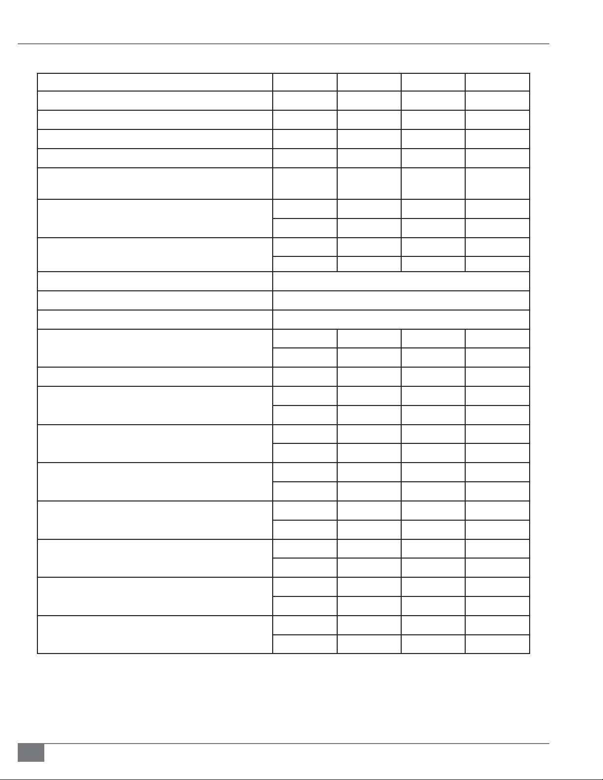
TABLE 1 OPERATING REQUIREMENTS SEE TABLE NOTES ON PAGE 25
Caliber Model Size
Input (BTU/Hr)
300 500 750 850
300,000 500,000 750,000 850,000
Output (BTU/Hr)
Natural Gas Consumption (ft3/hr)
Propane Consumption**(ft3/hr)
Gas Supply Pressure Minimum
Maximum
Dry Weight LB
KG
Operating Weight LB
KG
Control Voltage ( V/Hz/Ph)
Blower Voltage (V/Hz/Ph)
X. Electrical Connection*
Y. Condensate Drain Connection* IN
MM
Amp Draw
I. Gas Connection* IN
283,500 472,500 708,750 803,250
297 495 743 842
120 200 300 340
4.0
14
500 630 719 729
227 286 326 331
518 662 757 772
235 300 343 350
0.75 .075 0.75 0.75
19 19 19 19
2.1 3.6 3.6 3.6
.75 1 1.25 1.25
4.0
14
120/60/1
120/60/1
120/60/1
4.0
14
4.0
14
MM
G. Water Inlet/Outlet Connection* IN
MM
J. Flue Connection (ID)* IN
MM
H. Air Intake Connection***(OD) IN
MM
A. Boiler Width (including feet)* IN
MM
B. Boiler Height* IN
MM
C. Boiler Depth (Cabinet)* IN
MM
19.0 25.4 31.75 31.75
1.25 1.5 2 2
31.75 38.1 50.8 50.8
4.25 4.25 5.875 5.875
108 108 149 149
4.5 4.5 4.5 4.5
114 114 114 114
34.5 34.5 34.5 34.5
876 876 876 876
51.6 51.6 51.6 51.6
1310 1310 1310 1310
31.25 44 57.25 57.25
793 1117 1454 1454
2-4
© The Fulton Companies 2014
Page 11
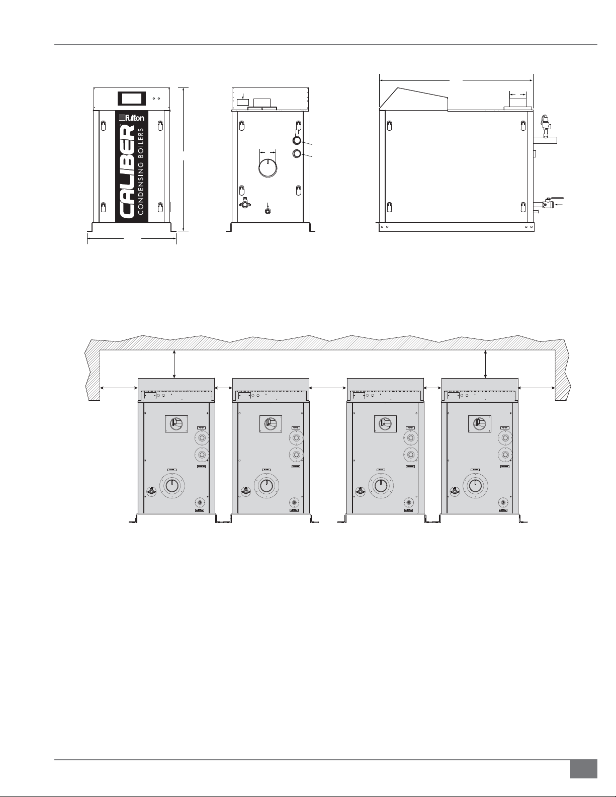
SECTION 2 CAL-IOM-2014-0129 INSTALLATION
C
X
H
* Refer to Figure 2
D
A
Front View
36"
B
J
Y
G Outlet
G Inlet
I
Right Side ViewBack View
FIGURE 1 CALIBER HYDRONIC BOILER
36"
24"6"24"
24"6"
FIGURE 2 CALIBER HYDRONIC BOILER SIDE CLEARANCES
Table 1 Notes:
Speci cations and dimensions are approximate. We reserve the right to change speci cations and dimensions without notice.
*See Figure 1.
**The use of propane is allowable with concentration of up to 5% propylene, commonly referred to as HD5. The use of o -standard grades of propane,
such as propane HD10 (10% propylene) is not permitted unless a system is in place to reduce propylene concentration to less than 5% prior to
reaching any fuel delivery piping. This is the responsibility of the customer. Verify propylene concentration with supplier prior to commissioning and
operation of equipment.
***Will accept 4” Fernco tting.
Questions? Please Contact Your Local Manufacturer’s Representative
2-5
Page 12
INSTALLATION CAL-IOM-2014-0129 SECTION 2
! WARNING
The discharge from the safety relief valve
must be arranged to ensure no danger
to personnel or equipment damage.
Provisions must be made to properly pipe
the safety relief discharge away from the
boiler to the point of discharge.
No shuto of any kind shall be placed
between the safety relief valve and
the boiler, or in the discharge pipe
between the valve and the atmosphere.
Doing so may cause an explosion from
overpressure.
The hydronic system should never be
ushed while the boiler is attached to the
system since the debris could accumulate
in the boiler and block water from passing
through the heat exchanger.
Ensure all labels on the boiler are legible.
All connections and safety devices, both
mechanical and electrical, must be kept
clean, with ease of access for inspection,
use and maintenance.
Do not store or use gasoline or other
ammable vapors and liquids or corrosive
materials in the vicinity of this or any other
appliances.
clearance is acceptable between one pair of Cailber boilers. A 24 in (610
mm) clearance is acceptable between pairs of Caliber boilers. Refer to
Figure 2.
3. Ensure all labels on the boiler will be fully visible for maintenance and
inspection.
Install Boiler Trim
Each Caliber boiler is supplied with a safety relief valve sized in accordance with
ASME requirements. The safety relief valve is shipped loose and must be eldmounted into the water outlet manifold.
Adhere to the following installation requirements:
1. The safety relief valve must:
» Be connected to the coupling located in the top rear outlet
section of the boiler.
» Be installed in the vertical position.
» Be installed with a 4 inch (101.6 mm) nipple between the boiler
and the safety valve.
NOTE: Safety relief valve size is determined by trim pressure and is supplied in the
trim kit along with appropriate bushing, inlet and outlet sizes.
The discharge of the safety relief valve is piped to the back of the boiler. The
installer must complete the piping to a safe location. The discharge pipe must:
» Not have a diameter less than the full area of the valve outlet.
» Be as short and straight as possible and so arranged as to avoid
undue stress on the valve.
4 CAUTION
Low ow conditions will cause excessive
cycling, damage and failure of equipment.
Circulating pump power supply must be
external to the boiler. The use of the SOLA
as a power supply is prohibited. The pump
contacts provided with the SOLA are for
controlling the pump only.
2-6
» Be supported by means other than the safety valve itself.
» Be piped to avoid danger of scalding personnel.
NOTE: Each boiler is shipped with a pressure-temperature gauge to be installed
in the outlet piping section of the boiler.
Install Water Piping
All water supplies contain some solids, dissolved gases or dissolved minerals.
These may promote corrosion, deposition and/or fouling of equipment. To
prevent these contaminants from impacting boiler performance, valve operation
and general pipe longevity, each location must be analyzed and treated
accordingly.
Adhere to the following for water piping installation:
1. Boiler has a maximum temperature di erential across the heat exchanger
at high re, and has a minimum ow requirement. Use Table 2 to identify
© The Fulton Companies 2014
Page 13

SECTION 2 CAL-IOM-2014-0129 INSTALLATION
ideal ow rates for the Caliber boiler.
TABLE 2 IDEAL FLOW RATES/GALLONS PER MINUTE*
Caliber Model 300 500 750 850
GPM at
Operating
Temperature of
20 F dT *
Minimum
Required
GPM
*typical
2. Pipe unions and isolation valves are recommended on
both water connections for ease of service.
3. Install piping so that the boiler is not supporting any
additional piping.
4. The top water connection on the back of the boiler is
the hot water outlet and must be connected as the
supply to the system. The bottom connection is the
return/boiler inlet. See Figure 1.
5. Install a dedicated hot water circulator, remote
mounted from boiler. Do not attach directly to the
boiler. Refer to Figures 3 through 5 for recommended
location of circulators.
NOTE: The Caliber boiler must be installed in a manner
which hydraulically separates the boiler, or primary
loop, from all other loops in the hydronic system. This
arrangement generally requires a dedicated boiler
circulator and primary/secondary piping.
30 45 70 80
8.8 15.4 17.6 19.8
to heating coils (located in air handling units where
they may be exposed to refrigerated air circulation),
such boiler piping systems shall be equipped with ow
control valves or other automatic means to prevent
gravity circulation of the boiler water during the cooling
cycle.
8. The boiler is not provided with a drain valve directly on
the boiler. A drain valve should be installed near the
system return (water inlet) connection to the boiler and
piped to a drain.
9. Before installing a Caliber boiler into a hydronic
loop, be sure that the system piping and any other
components of the system are clean and free of debris
and any foreign matter. The hydronic system must be
completely ushed prior to installing the boiler itself.
Install a strainer upstream of each boiler to ensure that
no foreign matter will have the opportunity to get
inside the heat exchanger.
Low Water Cut Off
The Caliber boiler comes with an installed ow-switch type
low water cut-o (LWCO). The LWCO does not require eld
piping or wiring. If the ow switch does not sense ow,
the boiler will shut down and an alarm condition will be
annunciated on the SOLA color screen display.
Meet Water Chemistry Requirements
System water chemistry requirements are as follows:
Maximum hardness of 8.5 grains/150 ppm
Acceptable pH range of 7.5-10
Solids less than 2500 ppm
6. Install manual purging valves in all loops and zones.
Install a pressure reducing (automatic ll) valve in the
cold water ll line to the boiler system. Check that the
proposed operation of zone valves, zone circulator(s)
and diverting valves will not isolate air separator(s) and/
or expansion tank(s) from the boiler. Clearance from hot
water pipes to combustibles must be at least 6 inches
(152.4 mm).
7. The boiler, when used in conjunction with a
refrigeration system, must be installed so the chilled
medium is piped in parallel with the boiler with
appropriate valves to prevent the chilled medium
from entering the boiler. If the boilers are connected
Questions? Please Contact Your Local Manufacturer’s Representative
Alkalinity less than 500 ppm
Foreign matter: Oils, fats, grease, and other matter
should be limited to 10 ppm.
Adhere to the following:
1. Refer to your water conditioning or chemical treatment
supplier for analysis and recommendations for proper
system conditions.
2. Follow a program with appropriate monitoring and
maintenance of system water conditions as provided by
your water conditioning or chemical treatment supplier.
2-7
Page 14
INSTALLATION CAL-IOM-2014-0129 SECTION 2
2-8
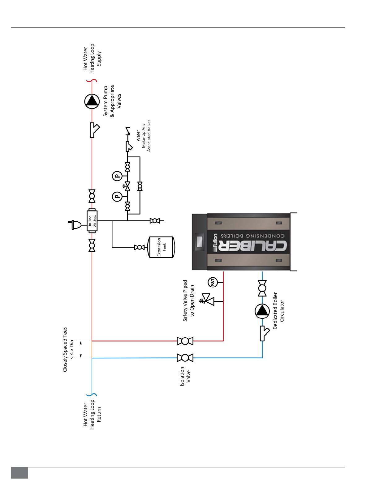
FIGURE 3 SAMPLE PIPING LAYOUT: SINGLE BOILER WITH PRIMARY/SECONDARY PIPING CONFIGURATION
© The Fulton Companies 2014
Page 15
SECTION 2 CAL-IOM-2014-0129 INSTALLATION
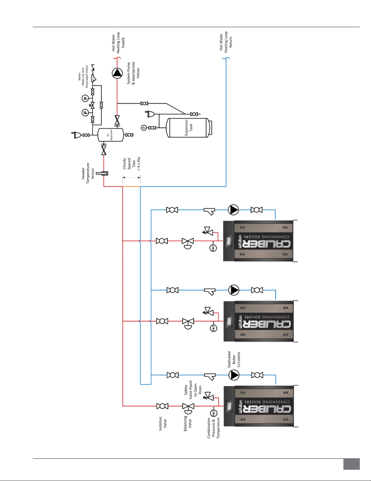
FIGURE 4 SAMPLE PIPING LAYOUT: MULTIPLE BOILERS IN A COMMON HYDRONIC LOOP, PRIMARY/SECONDARY WITH REVERSE RETURN
Questions? Please Contact Your Local Manufacturer’s Representative
2-9
Page 16
INSTALLATION CAL-IOM-2014-0129 SECTION 2
2-10
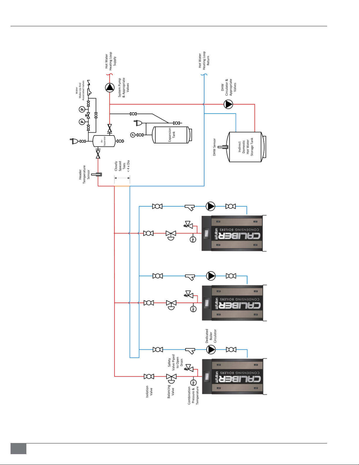
FIGURE 5 SAMPLE PIPING LAYOUT: MULTIPLE BOILERS IN A COMMON HYDRONIC LOOP, INDIRECT DOMESTIC HOT WATER
© The Fulton Companies 2014
Page 17
SECTION 2 CAL-IOM-2014-0129 INSTALLATION
3. Appropriate ow rates may be achieved through primary and secondary
ow loops. Please refer to Figures 3 - 5 for example systems. Multiple
pumps, valves and heating zones operating at a variety of conditions will
cause system ow to vary. System design professionals should consider the
variety of conditions the heating system will experience.
4. Operate the boiler in a closed-loop system using water or water/glycol
(not requiring a make-up water supply). A large amount of improperly
treated make-up water can cause premature failure of the heat exchanger
resulting from scale build up. Scale build up will reduce the e ciency and
useful life of the boiler.
5. Caliber boilers use high e ciency, small diameter tubing in the water side
of the boiler. Large particulates may become caught in the heat exchanger,
which could result in damage to the heat exchanger. Debris in the piping
must be kept to a minimum; use a suitable strainer upstream of the inlet to
the boiler.
TABLE 3 RECOMMENDED WATER TREATMENT CHEMICALS
Manufacturer Fernox Sentinel Sotin
Product
Inhibitor Protector/Alphi 11 X100, X500 Sotin 212
Universal Cleaner Restorer X300 --
Sludge Removal Protector.Restorer X400 Sotin 212
Prevent Freezing
! WARNING
All information in this manual is for
reference and guidance purposes,
and does not substitute for required
professional training, conduct,
and strict adherence to applicable
jurisdictional/professional codes and
regulations.
The boiler must be disconnected at
the boiler shut o valve from the
gas supply piping system during any
pressure testing of the system.
4 CAUTION
Small levels of chlorides and/or sulfur
presence in the combustion air or
fuel will negatively impact the heat
exchanger components. Any presence
of these contaminants will void the
warranty.
Some soaps used for leak testing are
corrosive to certain types of metals.
Rinse all piping thoroughly with
clean water after leak check has been
completed.
It is imperative to prevent freezing; adhere to the following:
If a water/glycol mix is to be used in the system, a hazard analysis should
be performed to determine proper use and disposal. No greater than 50%
glycol should be used.
Caliber boilers cannot be placed outdoors. Precautions for freeze
protection are recommended for boiler installations where freezing
potential exists and for installations that will use sealed combustion with
potential for outdoor temperature to fall below freezing point.
Prevent Oxygen Contamination
There are several ways to prevent boiler water oxygen contamination:
Minimize system leaks to minimize make up water requirement
Do not use open tanks or ttings
Do not use oxygen permeable materials anywhere in the water system
Repair leaks in the system quickly
Eliminate ttings wherever possible
Questions? Please Contact Your Local Manufacturer’s Representative
2-11
Page 18

INSTALLATION CAL-IOM-2014-0129 SECTION 2
! WARNING
All information in this manual is for
reference and guidance purposes,
and does not substitute for required
professional training, conduct, and strict
adherence to applicable jurisdictional/
professional codes and regulations.
4 CAUTION
Some soap used for leak testing is corrosive
to certain types of metals. Clean all piping
thoroughly after completing the leak check.
Never leave an opened manual air vent
unattended. In the event an opened vent is
left unattended, water damage could occur.
The presence of chlorides and/or sulphur
in the combustion air or fuel will negatively
impact the heat exchanger and void the
warranty.
Use air elimination devices in system piping
Eliminate System Air
There is a factory-installed air eliminator (air vent). The air eliminator must
not be altered or removed. Additional air elimination recommendations are as
follows:
1. If a sealed diaphragm-type expansion tank is used, install an air eliminator
in the hot water piping at the air separator.
2. If an air cushion type expansion tank is used, pipe tank directly into boiler
supply.
3. On multi-zoned systems (or a system with both space and domestic water
heating), air elimination must be provided either in the common piping or
on every loop.
4. When the boiler is installed at a higher level than baseboard radiation (if
used), air elimination must be provided directly above the unit.
Fill the Boiler With Water
Adhere to the following:
Circulating pump power supply must be
external to the boiler. The use of the SOLA
as a power supply is prohibited. The pump
contacts provided with the SOLA are for
controlling the pump only.
1. Close combination shuto /purge valve in supply, all drain cocks, the
shuto valve for the pressure reducing ( ll) valve, and all manual air vents.
2. Close the isolation valves to the boiler.
3. Open all other system shuto valves and one of the zone valves, the vent
on the combination shuto /purge valve and the shuto valve to the
pressure-reducing ( ll) valve.
4. Water will now begin to ll the system. Air will escape through the vent
on the combination shuto / purge valve. Continue lling until a constant
stream of water (no bubbling) is discharged from the vent.
5. Close the zone valve on the purged loop, and open the zone valve on
the next loop to be purged. When all air has escaped and only water is
discharged, close the zone valve. When all zones have been purged (one at
a time), close the vent on the combination shuto /purge valve.
6. At this point, the system has been initially lled. However, air pockets
may still remain at high points in the system and in heating loops above
the level of the combination shut/o purge valve. It is quite possible,
depending on the particular system, that all piping above the combination
shuto /purge valve still contains air. If manual vents are installed on the
system high points, these should be opened to vent these locations. When
only water is discharged from all vents, the initial purging is complete.
2-12
7. Open the combination shuto / purge valve (keep the vent closed). With
the gas shuto valve closed, turn on power to the boiler and operate the
circulator. Circulate the system water for approximately 30 minutes to
move all air to the automatic air separation point.
© The Fulton Companies 2014
Page 19

SECTION 2 CAL-IOM-2014-0129 INSTALLATION
8. Again, open manual air vents at high points of heating loop until a constant
stream of water is discharged from the vent. Close the vent and make sure
it’s watertight. Repeat procedure for all high points and for every zone.
9. Due to the nature of the heat exchanger utilized in the Caliber Hydronic
Boiler, pockets of air may still be trapped in the heat exchanger. To
discharge this air, rst open the automatic air vent located on the header of
the heat exchanger one full turn.
10. Cycle the circulator pump on for approximately 30 seconds, then shut o for
another 30 seconds. Repeat this step until no air is being discharged from
the automatic air vent. This will take at least 5 full cycles.
11. Close the cap on the automatic air vent to prevent any leakage from
occurring during normal operation.
12. Again, open manual air vents at high points of heating loop until a constant
stream of water is discharged from the vent.
13. Check temperature/pressure indicator reading, which should equal the
pressure-reducing ( ll) valve set pressure (minimum 12 psig). No more
water should be entering the system. Close the shuto valve on the coldwater ll line.
14. Visually inspect all pipe joints and equipment connections for leaks. If
necessary, drain system, repair leaks and re ll/purge the system. If no
pressure drop is detected for a period of two hours under pressure, the
system may be considered watertight.
15. When purging is completed, make sure the following are open —
combination shut-o /purge valve, shuto valve to pressure reducing ( ll
valve), shuto valve in cold water ll line, and shuto valve in return line.
4 CAUTION
Care needs to be taken to eliminate
oxygen from the water system, as
excess oxygen in the system will
reduce the life of any boiler. The
boiler warranty does not cover heat
exchanger replacement due to oxygen
contamination of boiler water.
Heat exchanger failure due to
inappropriate water quality, foreign
matter or debris damage is not covered
under the warranty.
If the piping system attached to this
unit will be chemically cleaned, the
boiler must be disconnected from the
system and a bypass installed so that
the chemical cleaning solution does
not circulate through the boiler.
The hydronic system should never be
ushed while the boiler is attached
to the system since the debris could
accumulate in the boiler and block
water from passing through the heat
exchanger. This will lead to premature
boiler failure.
16. Make sure the following are closed — all drain cocks, the vent on the
combination shuto purge valve, and all manual vents.
17. Reset zone valves to normal mode of operation and turn o power to
boiler.
Install Gas Piping
The Caliber boiler is factory test- red and combustion is adjusted per the boiler
data plate and test re sheet.
The gas train (Figure 6) components are UL-795 certi ed to operate at speci c
gas pressure requirements. If available gas pressure is greater than 14” W.C., a
lock-up style gas pressure regulator must be provided to reduce the provided
pressure to the acceptable range of 4” W.C. to 14” W.C. for natural gas, and 7” W.C
to 14” W.C. for propane.
Adhere to the following for gas piping installation:
1. See Table 4 for required natural gas pipe size, based on overall length of
pipe from the meter plus equivalent length of all ttings. Approximate
sizing may be based on 1,020 BTU for 1 cubic foot of natural gas.
Questions? Please Contact Your Local Manufacturer’s Representative
2-13
Page 20

INSTALLATION CAL-IOM-2014-0129 SECTION 2
2. Piping must be installed such that no piping stresses
are transmitted to the boiler. The boiler cannot be used
as a pipe anchor.
3. The boiler and all gas piping connections must be
pressure-tested and checked for leaks before being
placed into service. Test with compressed air or inert
gas, if possible.
4. The boiler must be disconnected at the boiler manual
shuto valve (located at the end of the supplied gas
train) from the gas supply piping system during any
pressure testing of the system at pressures in excess of
1/2 psig (14 inch W.C.).
5. Gas piping must be installed in accordance with
National Fuel Gas Code, ANSI Z223.1 (1991) or latest
addenda, and any other local codes which may apply.
6. The pipe and the ttings used must be new and free of
dirt or other deposits.
7. Piping must be of the proper size to ensure adequate
gas supply. A drip leg and union connection must be
installed upstream of the gas safety shut o valves.
installation is started, carefully check all piping
connections(factory and eld) for gas leaks. Use a soap
and water solution.
8. Connect gas supply line to the open end of the tee on
which the drip leg is installed.
9. When making gas-piping joints, use a sealing
compound resistant to lique ed petroleum gases. Do
not use Te on tape on gas line threads.
10. After gas piping is completed and before wiring
TABLE 4 NOMINAL PIPE SIZE
Nominal
Pipe Size
(“) (“) 90 Elb
1-1/4 1.380 3.45 6.9 950 ----- ----- ----- ----- ----- -----
1-1/2 1.610 4.02 8.04 1460 990 810 ----- ----- ----- -----
2 2.067 5.17 10.3 2750 1900 1520 1300 1150 950 800
2-1/2 2.469 6.16 12.3 4350 3000 2400 2050 1850 1500 1280
3 3.068 7.67 15.3 7700 5300 4300 3700 3250 2650 2280
4 4.026 10.1 20.2 15800 10900 8800 7500 6700 5500 4600
ID Equivalent Pipe
Length
Te e
(Feet)
(Feet)
Max Capacity in ft3 of natural gas per hour. Pressure drop of
0.5”wc/Equivalent length of pipe (feet)
20 40 60 80 100 150 200
FIGURE 6 TYPICAL GAS TRAIN
2-14
© The Fulton Companies 2014
Page 21

SECTION 2 CAL-IOM-2014-0129 INSTALLATION
Venting
Adhere to the following venting requirements:
1. The boiler can be installed with either sealed combustion or a conventional
venting arrangement. With either venting con guration, the di erence
in pressure readings at the boiler exhaust connection and air intake
connection cannot exceed 1.0” W.C. This equates to 70 feet (21.3 m) and 8
elbows when combining the distances on the air intake and exhaust with
the piping diameters matching the standard connections.
2. The pressure at the boiler exhaust connection must not exceed 0.05” W.C.
negative. This pressure must remain relatively constant throughout the
operation of the boiler.
3. The boiler should not be operated with a negative pressure in the boiler
room (unless there is sealed combustion [intake piped outside]). Pay
particular attention to other equipment installed in the boiler room such as
compressors and air handling units.
4. Consult your venting pipe supplier for assistance with sizing of vent
materials and other potentially required accessories.
Combustion Air Intake
! WARNING
All information in this manual is for
reference and guidance purposes,
and does not substitute for required
professional training, conduct,
and strict adherence to applicable
jurisdictional/professional codes and
regulations.
Do not store or use gasoline or other
ammable vapors and liquids or
corrosive materials in the vicinity of
this or any other appliances. Cements
for plastic pipe should be kept away
from all sources of ignition. Proper
ventilation should be maintained to
reduce the hazard and to minimize
breathing of cement vapors.
Never use open ame or smoke from
a cigarette, cigar, or pipe as a testing
method during boiler installation,
operation, or maintenance.
An air intake lter may be purchased as an option. The air intake lter must
be inspected and, if required, cleaned and/or replaced on a monthly basis at a
minimum.
Combustion Air Supply From the Boiler Room
Adhere to the following for installation:
1. Adequate combustion air and ventilation must be supplied to the boiler
room in accordance with local codes and NFPA54/ANSI Z233.1, Section 5.3,
Air for Combustion and Ventilation.
2. The boiler room must meet the NFPA criteria for a non-con ned space.
3. It is important to provide free access of air to the boiler. To burn fuel
properly, it requires one square inch opening of fresh air for every 1,000
BTU input of fuel (not less than 100 square inches).
4. Consistent proper ventilation of the boiler room is essential for good
combustion. Install two fresh air openings, one at a low level, within 12
inches (305 mm) from the oor but not less than 3 inches (76 mm), and
one at a higher level within 12 inches (305 mm) of the ceiling but not less
than 3 inches (76 mm) in the boiler room wall. This will provide a ow of
air to exhaust the hot air from the boiler room. Each opening must have
a minimum of 1 inch squared per 1000 Btu/hr, and be no less than 100
inches squared.
DO NOT USE GASOLINE, CRANKCASE
OIL OR ANY OIL CONTAINING
GASOLINE. If in doubt, contact
your Fulton representative prior to
operation.
4 CAUTION
Some soaps used for leak testing are
corrosive. Rinse piping with clean water
after leak testing is completed.
5. Consider the blocking e ect of louvers and grills.
Questions? Please Contact Your Local Manufacturer’s Representative
2-15
Page 22

INSTALLATION CAL-IOM-2014-0129 SECTION 2
! WARNING
All information in this manual is for
reference and guidance purposes,
and does not substitute for required
professional training, conduct,
and strict adherence to applicable
jurisdictional/professional codes and
regulations.
Do not use the boiler/burner as
support for ducted air piping.
Ducted piping must be supported
independently of the boiler.
Do not terminate venting into an
enclosed area.
For closet and alcove installations,
CPVC, polypropylene, or stainless
steel material must be used.
Foreign substances, such as
combustible volatiles in the
combustion system can create
hazardous conditions. If foreign
substances can enter the air stream,
the boiler combustion air inlet must
be piped to an outside location.
Combustion Air Piped From Outside Building Without Sealed
Combustion
Adhere to the following for installation:
1. If the boiler room is deemed to be a con ned space, two permanent ducts
connected to the outdoors must be installed.
2. After assembly, wipe excess cement from pipe at end of tting socket.
A properly made joint will show a bead around its entire perimeter. Any
gaps may indicate a defective assembly due to insu cient cement. Handle
joints carefully until completely set. Galvanized steel joints should be
sealed with adhesive aluminum tape.
NOTE: Assembly should be completed within 20 seconds after last application of
cement. Do not use a hammer to insert pipe.
Air Piped From Outside Boiler Room
Adhere to the following:
1. The combustion air supply can be piped directly to the air inlet (Figure 3) of
the boiler.
2. An optional rubber air intake coupling may be used with boilers speci ed
for installation with ducted air supply to connect the intake piping to the
boiler air inlet.
3. The air intake must be piped out of the building if the boiler room contains
contaminated air. See Figures 7 and 8.
Regular maintenance of the
lter is required (as per the lter
manufacturer’s recommendations) to
maintain the warranty.
Particulate matter or chemicals in
the combustion air supply to the
boiler will cause damage or failure to
the burner and is not covered under
warran ty.
Do not mix vent systems of di erent
types or manufacturers.
Exhaust Venting
The Caliber boiler is equipped with a round exhaust vent connection (Figure 7) at
the lower rear of the boiler.
Standard Venting Confi guration, Category II or IV
The Caliber boiler is standardly con gured as a Category II or IV appliance.
The vent connection sizes are adequate for a Category II or IV arrangement.
Venting material must be appropriate for positive pressure applications where
condensing occurs in the stack.
Adhere to the following:
1. The boiler requires a category IV stack. The Caliber is factory con gured
with a stack temperature limiting function set to 200 degrees Fahrenheit,
which is appropriate for PVC and CPVC venting materials. If stainless
venting is used, the stack material must be either AL-29-4C or 316L
stainless steel and comply with UL-1708 or UL-103, and the stack
temperature limit function may be disabled. If PVC exhaust venting
2-16
© The Fulton Companies 2014
Page 23

SECTION 2 CAL-IOM-2014-0129 INSTALLATION
is used, the rst 8 inches (204 mm) must be CPVC material. Venting
installation must comply with National Fuel Gas Code, ANSI Z233.1, Part 10
or applicable provisions of local building codes.
2. Do not utilize automatic vent dampers or barometric dampers with the
Caliber boiler. Because the exhaust system operates at a positive pressure,
utilizing dampers could result in exhaust gases leaking into the boiler
room.
3. The exhaust line must be sloped down toward the boiler with a pitch of
at least 1/4” per foot. Failure to do so can result in a condensate pocket,
which can result in an inoperative boiler. There must be no low spots in the
exhaust pipe, as this can also result in a condensate pocket. A high spot is
acceptable, provided the pitch from the high spot is maintained back to
the boiler. Always avoid rigid connections between piping and structural
members of the building. The exhaust vent installer should be familiar
with Federal Codes as well as local codes and regulations.
4. Follow vent manufacturer’s instructions for installation of exhaust venting.
Refer to Table 5 for acceptable venting materials.
TABLE 5 ACCEPTABLE VENTING MATERIALS
Venting
Material
PVC 200 F (93 C) 200 F (93 C)
CPVC 200 F (93 C) 200 F (93 C)
Polypropylene
(InnoFlue)
AL294C 550 F (287 C) 200 (93 C)
Max. Flue
Temperature
248 F (120 C) 200 F (93 C)
Max. Water
Setpoint
! WARNING
Do not use the boiler as support for
ducted air piping. Ducted piping
must be supported independently of
the boiler.
Cements for plastic pipe are
ammable liquids and should
be kept away from all sources of
ignition. Proper ventilation should
be maintained to reduce the hazard
and to minimize breathing of cement
vapors. Avoid contact of cement with
skin and eyes.
4 CAUTION
Insulation should not be used on PVC,
CPVC, or polypropylene materials as it
may elevate pipe wall temperatures,
resulting in the potential for vent
material failure.
Appropriate cement must be used
when joining PVC to CPVC materials.
Note: Fulton accepts no liability for installation of any venting, including the selection of venting materials.
If PVC is used, the rst 8” must be CPVC. Do not use cellular/foam core pipe.
5. Stainless steel or galvanized steel pipe is recommended for all condensate
drain piping. Be aware that condensate drain piping can be as hot as the
exhaust stack on the boiler, and precautions should be taken to ensure this
pipe would not cause burns or other injuries to personnel that may be in
the boiler room.
6. Ensure that the condensate drain piping will not be exposed to
temperatures where water/condensate will freeze in the lines.
Sizing Air Intake and Exhaust Piping
CATEGORY II OR IV INSTALLATIONS, INDIVIDUAL PIPING FOR EACH BOILER:
The minimum ue stack length is 5 feet and the combined pressure drop of
the air intake and exhaust piping should not exceed 1.0”wc. This is typically the
equivalent of 70 ft and 8 elbows (combining the distances between the intake
and exhaust pipes). If a negative pressure is present in the stack during some
operating conditions, it should never be below -0.05”wc.
Questions? Please Contact Your Local Manufacturer’s Representative
2-17
Page 24

INSTALLATION CAL-IOM-2014-0129 SECTION 2
FIGURE 7 COMBUSTIBLE WALL PENETRATION DETAILS
Common Air Intake and Exhaust Venting of
Multiple Boilers
Combining multiple Caliber boilers into a common pipe for
combustion air supply, exhaust, or both is only permitted on a
case by case basis and must be accomplished with a Fultonengineered solution.
Fulton Part No. 2-30-002018 Common Venting Kit can be
optionally installed at the factory on CAL-750 and CAL-850
models. The installation location is between the burner ange
and the blower motor. When the blower motor starts, it will
overcome the valve that is magnetically closed (See Figure
9). When the blower motor is is o , gravity will cause the
2-18
check valve to close and prevent ue gases from recirculating
through an idle boiler. This component is required when
Caliber boilers are common vented.
Adhere to the following:
1. The engineered solution must guarantee the
prevention of ue gases moving backwards through
idle boilers. This is important in preventing ue
gases from entering the mechanical room if sealed
combustion is not being used, as well as preventing
ue gases from corroding the heat exchanger or other
components within the boiler cabinet.
2. Caliber boilers cannot be common vented with other
types of equipment.
© The Fulton Companies 2014
Page 25

SECTION 2 CAL-IOM-2014-0129 INSTALLATION
FIGURE 8 VENTING CONFIGURATIONS
Intake Duct Sizing
Adhere to the following:
1. Air intake ducting must be sized in conjunction with the
exhaust venting to provide no greater than a 1.0” W.C.
combined pressure drop. This equates to 70 feet and 8
elbows when combining the distances on the air intake
and exhaust with the piping diameters matching the
standard connections.
2. The installation of a recognized termination screen
is required. Contact your local venting supplier for
assistance in venting sizing.
3. Air Intake pipes and ttings shall be Schedule 40
PVC pipe or galvanized steel. All Schedule 40 PVC
pipe, ttings, primer and cement must conform
with American National Standard Institute and the
American Society for Testing and Materials (ANSI/ASTM
standards.)
no lumps, un-dissolved particles or any foreign matter
that adversely a ects the joint strength or chemical
resistance of the cement. The cement shall not show
gelation, strati cation, or separation that cannot be
removed by stirring.
5. Refer to PVC manufacturer’s requirements for proper
installation.
4. Intake PVC piping must be assembled using cement.
This will ensure that the intake is airtight and will not
allow contaminates from the boiler room into the
boiler. The cement shall be free owing and contain
Questions? Please Contact Your Local Manufacturer’s Representative
FIGURE 9 CHECK VALVE FOR COMMONVENTED BOILERS
2-19
Page 26

INSTALLATION CAL-IOM-2014-0129 SECTION 2
! WARNING
Use of automatic vent dampers or
barometric dampers with the Caliber
boiler in positive pressure systems
may result in exhaust leaking into the
boiler room.
It is critical to ll the condensate trap
with water prior to the rst time the
boiler is started up. Failure to do so
could allow ue gas products into the
boiler installation space, resulting in
personal injury or death.
he exhaust vent installer should be
familiar with Federal Codes as well
as local codes and regulations.
Fulton cannot assume responsibility
for an air intake or exhaust
arrangement where Caliber boilers
are common vented with any other
type of equipment.
Condensate Drain Piping
A condensate trap and drain is integral to the boiler. The trap is located inside
the cabinet, and the drain connection is at the back of the boiler. All condensate
piping is to be pitched away from this drain connection to ensure proper
draining.
NOTE: The trap is equipped with a high condensate alarm functionality, which
will annunciate via the SOLA control if the ue gas condensate is not draining
away properly.
Adhere to the following for condensate drain piping installation:
1. A condensate collecting tank and condensate pump will be required if a
oor drain is not available to discharge to (Collecting tank and pump are
not supplied with the boiler). Complete condensate drain kits are available
from Fulton.
2. It is recommended that all condensate piping be galvanized or stainless
steel and should be free of leaks. Do not use copper or carbon steel piping.
3. Install the condensate piping to the condensate drain at the back of the
boiler.
4 CAUTION
Failure to slope the exhaust line toward
the drain with a pitch of at least 1/4”
per foot may result in a condensate
pocket, which can result in an
inoperative boiler.
To prevent the possible re-circulation
of ue gases, the vent designer must
take into consideration such things
as prevailing winds, eddy zones,
building con gurations, etc. It is the
responsibility of the installer to locate
the exhaust duct in such a way that it
does not become blocked due to snow,
ice, and other natural or man-made
obstructions.
Do not locate the vent termination too
close to shrubbery as ue products may
stunt their growth or kill them.
NOTE: Be aware that condensate drain piping may be as hot as the exhaust stack
on the boiler. Precautions should be taken to ensure this piping will not cause
burns or other injuries to personnel in the boiler room.
4. Ensure that the condensate drain piping will not be exposed to
temperatures at which the ue gas condensate has the potential of
freezing.
Venting Terminations
Adhere to the following for installation (see Figure 10):
1. All vent pipes and ttings must be installed with appropriate air space
clearances to combustibles. These air space clearances apply to indoor or
outdoor vents—whether they are open, enclosed, horizontal or vertical or
pass through oors, walls, roofs, or framed spaces. The air space clearances
should be observed to joists, studs, sub oors, plywood, drywall or plaster
enclosures, insulating sheathing, rafters, roo ng, and any other material
classed as combustible.
2. The required minimum air space clearances also apply to electrical wires
and any kind of building insulation.
3. Adequate provision must be made to support the weight of the exhaust
venting. It cannot be supported by the boiler exhaust connection.
2-20
4. Listed termination parts must be used.
5. Select the air intake point of penetration where a minimum of 1/4” per foot
© The Fulton Companies 2014
Page 27

SECTION 2 CAL-IOM-2014-0129 INSTALLATION
upward pitch can be maintained.
6. When penetrating a non-combustible wall, the hole through the wall must
be large enough to maintain the pitch of the vent and provide sealing. Use
adhesive material to seal around the vent on both sides of the wall. When
penetrating a combustible wall, a wall thimble must be used. See Figure 8
for installation instructions. Minimum wall thickness through which vent
system may be installed is 3.25 inches (82.5 mm). Maximum wall thickness
through which vent system may be installed is 20 inches (508 mm).
! WARNING
All information in this manual is for
reference and guidance purposes,
and does not substitute for required
professional training, conduct,
and strict adherence to applicable
jurisdictional/professional codes and
regulations.
Do not use any dangerous source of
re or smoke (e.g., lighter, candle) to
test equipment at any time.
Assure all electrical connections are
powered down prior to attempting
replacement or service of electrical
components or connections of the
boiler.
4 CAUTION
FIGURE 10 VENTING TERMINATIONS
Wall Thimble Installation
Adhere to the following for installation (see Figure 11):
1. The thimble is inserted through the wall from the outside. Secure the
outside ange to the wall with nails or screws, and seal with adhesive
material.
Never install a barometric damper on
ue systems designed with positive
pressure.
2. Install the inside ange to the inside wall, secure with nails or screws, and
seal with adhesive material.
3. Pass the vent pipe through the thimble from the outside and join to the
rest of the vent system.
Questions? Please Contact Your Local Manufacturer’s Representative
2-21
Page 28

INSTALLATION CAL-IOM-2014-0129 SECTION 2
! WARNING
All information in this manual is for
reference and guidance purposes,
and does not substitute for required
professional training, conduct,
and strict adherence to applicable
jurisdictional/professional codes and
regulations.
Fulton cannot assume responsibility
for an air intake or exhaust
arrangement where Caliber boilers
are common vented with any other
type of equipment.
Cements for plastic pipe are
ammable liquids and should
be kept away from all sources of
ignition. Proper ventilation should
be maintained to reduce the hazard
and to minimize breathing of cement
vapors. Avoid contact of cement with
skin and eyes.
Assure all electrical connections are
powered down prior to attempting
replacement or service of electrical
components or connections of the
boiler.
4. Seal the pipe to the thimble ange with adhesive material.
5. Install two pipe retaining clamps around the intake as well as vent pipes
on both ends of the wall thimble (on the inside and outside of the wall)
through which intake and vent pipes are passed. They will prevent the
intake and vent pipes from being pushed or pulled.
Vent Termination
Adhere to the following for installation:
1. To prevent the possible re-circulation of ue gases, the vent designer
must take into consideration such things as prevailing winds, eddy zones,
building con gurations, etc. Fulton cannot be responsible for the e ects
such adverse conditions may have on the operation of the boilers. It is
important to locate the intake and exhaust terminations in such a way that
it does not become blocked due to snow, ice, and other natural or manmade obstructions.
2. If the exhaust vent terminates within 10 ft (3.04 m) horizontally of the air
inlet, the exhaust vent must be at least 4 ft (1.22 m) above the inlet. See
Figure 12. Dimensions provided are minimum, and may or may not be
su cient for conditions at a speci c job site.
3. Consider the harmful e ects to landscaping/shrubbery from the slightly
acidic nature of ue gas condensate when locating the vent termination.
In addition, adhere to the following for Horizontal Installations:
1. The vent termination is joined to the vent pipe outside the wall. Use the
same joining procedures for vent pipe and ttings. The termination of the
vent system must be at least 12 inches (304.8 mm) above the nished
grade, or at least 12 inches (304.8 mm) above normal snow accumulation
level (for applicable geographical areas). The termination of the vent
system shall not be located in tra c areas such as walk ways, adjacent
buildings, operable windows and building openings unless the venting
system is at least 7 ft (21.3 m) above nished grade, (National Fuel Gas
Code, ANSI Z223.1). The vent terminations must be at least 4 feet (1.22
m) horizontally from electric meters, gas meters, regulators, and relief
equipment.
2-22
2. When installing inlet and exhaust terminations on the same wall, the
exhaust outlet must be installed a minimum of 4 feet (1.22 m) above and
downwind from air supply inlet to prevent exhaust recirculation. Under
certain wind conditions, some building materials may be a ected by ue
products expelled in close proximity to unprotected surfaces. Sealing
or shielding of the exposed surfaces with a corrosion resistant material,
such as an aluminum sheet, may be required to prevent staining or
deterioration.
In addition, adhere to the following for Vertical Installations:
1. The minimum vent height should extend at least 3 ft (.914 m) above the
roof, or at least 2 ft (.609 m) above the highest part of any structure within
10 ft (3.04 m) of the vent.
© The Fulton Companies 2014
Page 29

SECTION 2 CAL-IOM-2014-0129 INSTALLATION
A
SCREW OR BOLT EACH THUMBLE COLLAR
TO WALL (TYPICAL 4 PLACES) ORIENT
COLLAR AND CLAMPS AS REQUIRED
PIPE RETAINING
CLAMP, TYPICAL
3 1/2 IN. OR
4.35 CM
AIR GAP
ALL AROUND
THRU PIPE
DIAMETER "C"
STAINLESS
EACH SIDE
DIAMETER "B"
ADJUSTABLE
WALL THUMBLE
WIDTH TO VARY WITH
WALL THICKNESS
END VIEW
DIAMETER "A"
COLLAR
VARIABLE
(3 1/4 IN. MIN.) - (20 IN. MAX.)
(8.255 CM MIN. - 50.8 CM MAX.)
FIGURE 11 WALL THIMBLE INSTALLATION
4FT / 122 CM
(MINIMUM)
4FT / 122 CM ABOVE AIR INTAKE PIPING
SCREENED INLET
IF SNOW ACCUMULATION
IS APPLICABLE, OPENING
TO BE 1 FT. / 30 CM ( MIN. )
BOVE THIS NORMALLY
EXPECTED LEVEL.
ADHESIVE SEAL
STORM COLLAR
ADJUSTABLE
FLASHING
4" PVC PIPE
WHEN WITHIN 10 FT HORIZONTALLY
ROOF
SUPPORT
METAL PLATE
FIRE STOP
NOTE:
AIR INTAKE AND EXHAUST TERMINATION
SHOULD BE SEPERATED AS FAR AS POSSIBLE
TO PREVENT FLUE GAS RECIRCULATION
DURING DIFFERENT WIND CONDITIONS.
EXHAUST STACK IS DOWNWIND
OF AIR INTAKE OPENING
TYPICAL ROOF PENETRATIONS
( SUGGESTED TERMINATION CONFIGURATIONS )
ADJUSTABLE
FLASHING
DO N OT PLACE
INSULATION
IN REQUIRED AIR
SPACE CLEARANCE
FIGURE 12 ROOF PENETRATION DETAILS
Questions? Please Contact Your Local Manufacturer’s Representative
MAINTAIN MIN 9" / 22.86 CM
AIR SPACE CLEARANCES
TO COMBUSTABLES,
WIRES AND INSULATION
2-23
Page 30

INSTALLATION CAL-IOM-2014-0129 SECTION 2
Electrical Connections
Adhere to the following when installing electrical
connections:
1. Install wiring and ground boiler in accordance with
authority having jurisdiction, or in absence of such
requirements utilize National Electrical Code, ANSI/
NFPA 70.
2. This boiler requires an independent 120V 60Hz single
phase connection. Connect power to the terminal
strip as supplied on the inside cover of the panel box.
3. Refer to Figure 13 for a sample electrical diagram.
Please note, Figure 13 is for general reference purposes
only and is not to be used for construction purposes.
NOTE: Connect a ground wire to green colored ground lug in
electrical control box.
2-24
© The Fulton Companies 2014
Page 31

SECTION 2 CAL-IOM-2014-0129 INSTALLATION
Questions? Please Contact Your Local Manufacturer’s Representative
2-25
Page 32

INSTALLATION CAL-IOM-2014-0129 SECTION 2
2-26
A
B
C
FIGURE 12 EXAMPLE ELCTRICAL DRAWING FOR REFERENCE PURPOSES ONLY
© The Fulton Companies 2014
Page 33

SECTION 2 CAL-IOM-2014-0129 INSTALLATION
1
7
8
5
3
6
11
10
FIGURE 12 EXAMPLE ELCTRICAL DRAWING FOR REFERENCE PURPOSES ONLY
Questions? Please Contact Your Local Manufacturer’s Representative
NOTES:
1. ( ) DENOTES FIELD WIRING BY OTHERS.
2. REMOVE FACTORY INSTALLED JUMPER FOR E-STOP CONNECTION.
3. FOR BMS INTERFACE IF LEAD/LAG IS USED, USE COM2 ON DISPLAY,
IF STAND ALONE BOILER OR LEAD/LAG IS NOT USED BMS CONNECTS TO J3-MB1.
4. PB1 IS A COMBINATION PILOT LIGHT - PUSH BUTTON ASSEMBLY.
2-27
Page 34

INSTALLATION CAL-IOM-2014-0129 SECTION 2
2-28
© The Fulton Companies 2014
Page 35

OPERATION
INTRODUCTION
1
INSTALLATION
2
OPERATION
MAINTENANCE
WARRANTY & PARTS
3
4
5
Questions? Please Contact Your Local Manufacturer’s Representative
3-1
Page 36

OPERATION CAL-IOM-2013-1001 SECTION 3
! WARNING
All information in this manual is for
reference and guidance purposes,
and does not substitute for required
professional training, conduct, and strict
adherence to applicable jurisdictional/
professional codes and regulations.
Failure to follow instructions may result
in a re or explosion, causing property
damage, personal injury, or loss of life.
This boiler is equipped with an ignition
device, which automatically lights the
burner. Do not try to light the burner by
hand.
Do not store or use gasoline or other
ammable vapors and liquids in the
vicinity of this or any other appliances.
WHAT TO DO IF YOU SMELL GAS • Do not
try to light any appliance. • Do not touch
any electrical switch; do not use any phone
in your building. • Immediately call your
gas supplier from a neighbor’s phone.
Follow the gas supplier’s instructions. • If
you cannot reach your gas supplier, call
the re department. A quali ed installer,
service agency or the gas supplier, must
perform installation and service.
Perform Pre-Start-Up Inspection
Prior to start-up, perform the following:
1. Check around the boiler area for the scent of gas. Be sure to check next to
the oor, as some gas is heavier than air and will settle. If you smell gas:
» Do not try to light any appliance.
» Do not touch any electrical switch; do not use any phone in your
building.
» Immediately call your gas supplier from a neighbor’s phone.
2. Ensure the boiler is located with the proper clearances as shown in the
Clearances and Serviceability section of this manual.
3. Ensure that relief valves have been properly piped to oor drains.
4. Ensure ue gas from the boiler is properly vented.
5. Ensure the water system has been ushed and is free of debris.
6. Ensure combustion air openings are not obstructed in any way and have
adequate capacity.
7. Ensure there are no ammable liquids, materials or hazardous fumes
present in the environment.
8. Ensure nothing was damaged or knocked loose during installation and/or
shipment, including main gas train and trim assembly.
Fill and Purge the System
3-2
Refer to Installation section of this manual for procedure. Attempting to start
the boiler prior to Fill and Purge may result in dry re, which can cause injury or
property damage, and is not covered by warranty.
SOLA Control Program Presets
The SOLA control has been factory-programmed and requires no alteration
of program presets. Only factory-trained personnel should attempt to alter
password protected preset values.
Commission The Boiler
Adhere to the following when commissioning the boiler:
1. Verify with authorized personnel that the gas lines have been purged. Do
not proceed without veri cation.
2. Familiarize all personnel on all aspects of boiler use, safety, and contents
of this manual. This includes, but is not limited to, the use of the controls,
lighting, and shutdown procedures.
© The Fulton Companies 2014
Page 37

SECTION 3 CAL-IOM-2013-1001 OPERATION
3. Review the unit-speci c control schematics, and follow appropriate
instructions.
Test of Ignition Safety System
Test the ignition system safety shuto as follows:
1. Remove the black plug/connector from the main gas valve (it is attached
with a central screw).
2. With the main gas cock (inlet manual gas valve) open, a call for heat will
cycle the burner on. After all the safety limits (gas pressure, water ow, and
temperature) are satis ed, the blower will run and pre-purge the boiler.
3. Once the purge is complete (15-30 seconds), the ignition transformer will
be energized. There will be a 4 second trial for ignition period.
NOTE: The main gas valve will not open because there is no power to the
valve. As a result, no ame will be established and the ame safeguard will
not receive a ame signal from the ame rod.
4. After 4 seconds, the ame safeguard programmer will assume a “Flame
Failure” condition and go to a “lockout” mode. Lockout will require manual
reset of the ame safeguard. The control will allow one retry before locking
out.
5. After completing this test, turn o the boiler and reconnect the wires to
the main gas valve.
! WARNING
Do not attempt to start the boiler for
any testing before lling and purging
the boiler. A dry re will seriously
damage the boiler and may result in
property damage or personnel injury
and is not covered by warranty.
Before commissioning the boiler,
verify with authorized personnel that
the gas lines have been purged.
Never attempt to operate a boiler
that has failed to pass all the safety
checks.
Never leave an opened manual air
vent unattended. In the event an
opened vent is left unattended, water
damage could occur.
Check daily that the equipment area
is free and clear of any combustible
materials, including ammable
vapors and liquids.
Perform Test of Low Water Cut Off
This boiler is equipped with a ow switch type low water cut-o in the outlet
nozzle. Once the boiler is full of water the following test can be accomplished:
1. Turn the boiler o .
2. Turn dedicated boiler pump o .
3. Turn the boiler back on. Boiler will begin to purge, at which point it will
lock out, annunciating “ilk o : ow switch”. Reset lockout, and turn pump
back on.
4. Perform appropriate test for any external or factory-installed probe-type
low water cut-o .
Perform Test of Limit Controls
Fire the boiler and test the high limit control as follows:
1. Access the High Limit screen of the SOLA control.
2. Alter high temperature limit setpoint to a value lower than the anticipated
loop temperature. Turn the boiler on. Water temperature will rise until the
4 CAUTION
Do not use this equipment if any part
has been under water (or subjected to
heavy rains/water if the equipment
does not have NEMA 4 wiring, controls
and instrumentation). Immediately
call a quali ed service technician to
inspect the equipment and to replace
any part of the control system and/or
gas control(s) which have been under
water.
Commissioning/Start up by a nonFulton authorized person will void the
product warranty.
Please read these instructions and
post in an appropriate place near the
equipment. Maintain in good legible
condition.
Questions? Please Contact Your Local Manufacturer’s Representative
3-3
Page 38

OPERATION CAL-IOM-2013-1001 SECTION 3
! WARNING
Non-Fulton product information is for
reference purposes only. No Fulton
document should substitute for full
review of documentation available
from the component manufacturer.
4 CAUTION
After checking controls by manual
adjustment, make sure they are always
reset to their proper settings.
Use only your hand to turn the valve
handle. Never use tools. If the knob
will not turn by hand, don’t try to
repair it. Call a quali ed service
technician. FORCE OR ATTEMPTED
REPAIR MAY RESULT IN A FIRE OR
EXPLOSION.
boiler locks out. This condition has to be manually reset. Alter the high
limit setpoint temperature to normal level, typically 10-20 degrees above
set point.
Perform Test of Low Gas Pressure Switch
Test the low gas pressure switch as follows:
1. With the boiler running increase the low gas pressure setpoint until a lock
out is annunciated.
2. Reset the switch to normal level.
3. Restart the boiler.
Perform Test of High Gas Pressure Switch
Test the high gas pressure switch as follows:
1. Close the downstream main gas cock and start the boiler.
2. Once the trial for ignition period is reached, the main gas valve will open,
pressurizing the line. This will trip the high gas pressure switch.
3. Manually reset the high gas pressure switch after it trips.
Perform Test of Air Switch
Fire the boiler and test the air switch as follows:
1. At low re turn the adjustment on the switch clockwise until the switch
trips and the boiler shuts down.
2. Back out the adjustment to previous position.
Test of High Back Pressure Switch
Fire the boiler and test the high back pressure switch as follows:
1. At high re, turn the adjustment on the switch toward the low end of the
scale until it opens and the boiler shuts down.
2. Set the scale to 50% above the point at which the switch opened in Step 1.
Normal Operation of the Boiler
3-4
Under normal operating circumstances, this boiler functions as a fully automatic
appliance. The automatic control senses the water outlet temperature and
res the boiler when heat is needed by the system. Additionally this boiler may
function as part of an integrated building management system.
Excessive cycling will reduce the useful life of any piece of mechanical
© The Fulton Companies 2014
Page 39

SECTION 3 CAL-IOM-2013-1001 OPERATION
equipment. Caliber boilers should be operated and controlled so that the boiler
cycles less than 12,000 times per year.
Outlet water temperature, fan speed and set point are displayed on the SOLA
touch screen display on the front of the boiler. Figure 14 shows a sample Status
Screen display on the SOLA control.
! WARNING
Non-Fulton product information is for
reference purposes only. No Fulton
document should substitute for full
review of documentation available
from the component manufacturer.
4 CAUTION
When making changes to the controls
pro le, a combustion analyzer is
required.
FIGURE 14 SAMPLE STATUS SCREEN OF SOLA CONTROL
CHANGING THE OPERATING SET POINT
From the main screen, perform the following steps:
1. Tap Con gure.
2. Tap Central Heat Con guration.
3. Tap CH Set Point.
4. Tap Clear.
5. Enter the New Set Point.
6. Tap OK.
7. Tap the escape arrow in top right hand corner (see Figure 15).
SETTING COMBUSTION
To Set Combustion, perform the following steps:
1. Obtain the following tools: Calibrated combustion analyzer, manometer to
measure inlet gas pressure.
2. From home screen tap Operation.
Questions? Please Contact Your Local Manufacturer’s Representative
3-5
Page 40

OPERATION CAL-IOM-2013-1001 SECTION 3
! WARNING
Non-Fulton product information is for
reference purposes only. No Fulton
document should substitute for full
review of documentation available
from the component manufacturer.
This boiler is equipped with an
ignition device which automatically
lights the burner. Do not try to light
burner by hand.
3. Tap the yellow background rpm box next to ring rate. (See Figure 16).
4. Under Firing Rate Control, tap Manual in Run. Refer to Figure 17.
FIGURE 15 CHANGING THE OPERATING SET POINT
3-6
FIGURE 16 LOCATION OF FIRING RATE/RPM BOX
FIGURE 17 SETTING COMBUSTION ON SOLA CONTROL
© The Fulton Companies 2014
Page 41

SECTION 3 CAL-IOM-2013-1001 OPERATION
5. Using test re sheet, enter the rpm value (light o ) in the Manual Firing
Rate box.
6. Once the rpm value is entered, tap OK.
7. Return to the status screen.
8. Turn the local/o /remote switch to the local position.
9. Once burner has started and ame signal has been veri ed, return to the
Manual Firing Rate box.
10. Increase the ring rate in 500 rpm increments until high re rpm value
from the factory test re sheet is reached.
At each point, check combustion. CO2/CO should remain constant
throughout ring range. Monitor inlet gas pressure during combustion.
11. Once the high re rpm setting is reached, make adjustments on the
gas ratio valve ow rate to match factory test re settings. The ow rate
adjustment requires a 3mm hex wrench.
NOTE: Turning the screw counterclockwise increases gas ow; clockwise
decreases gas ow.
! WARNING
All information in this manual is for
reference and guidance purposes,
and does not substitute for required
professional training, conduct, and strict
adherence to applicable jurisdictional/
professional codes and regulations.
4 CAUTION
Only factory-trained personnel should
attempt to alter password protected Control
preset values.
NOTE: The acceptable combustion range of CO
maintain NOx < 20%, set combustion to approximately 8.4% CO
-speci c factors may contribute to the determination of the appropriate
combustion range of CO
NOTE: Combustion changes are made at high and low re only, as the gas
ratio valve has a 1:1 ratio.
12. Manually decrease the ring rate by 500 rpm increments. Observe
combustion down to the low re rpm setting (minimum) on the factory
test re sheet. If required, low re combustion may be altered by adjusting
the o set adjustment screw with either a Torx®T40 or a 5mm hex wrench.
NOTE: Turning the screw counterclockwise decreases gas ow; clockwise
increases gas ow.
13. If changes are made (at either high or low re), recheck the entire range.
14. Before leaving the Firing Rate screen, tap Automatic ring rate control. Do
not leave the unit in the Manual in Run mode.
2, and other combustion parameters.
2 is 8.0% to 9.8%. To
2. Site
Shut Down Procedures
Normal Shut Off Procedures
1. Place the local/o /remote switch in the o position.
Questions? Please Contact Your Local Manufacturer’s Representative
3-7
Page 42

OPERATION CAL-IOM-2014-0129 SECTION 3
2. Close all manual gas valves.
3. Turn o electrical power.
Emergency Shut Off Procedures
The main gas cock should be closed immediately. If
overheating occurs or the gas supply fails to shut o , do not
turn o or disconnect the electrical supply to the pump.
Instead, shut o the gas supply at a location external to the
boiler.
Shutting the Boiler Down for an Extended Period
of Time
If the boiler is to be shut o for a period greater than 3
months:
1. Perform normal shut down procedure, see above.
2. Isolate water supply and ow circuit from boiler.
3. Drain boiler.
4. Disconnect electrical supply.
Starting Boiler After Prolonged Shutdown
Perform initial start up procedures as described in this
manual.
3-8
© The Fulton Companies 2014
Page 43

SECTION 3 CAL-IOM-2014-0129 OPERATION
SOLA Control Features
Refer to the Table below for additional SOLA Control screen displays.
Viewing the Flame Signal
1. The ame signal can be viewed
from the main/home screen or
in main screen details.
2. Tap Details in main screen,
then scroll to right by pressing
the arrow until Flame Detection
is displayed.
3. Tap the escape arrow in top
right hand corner to return to
main operating screen.
Cycle and Run Hours
Monitoring
Burner cycles, burner run time, and
pump cycles may be viewed from the
Statistics Con guration screen on the
Control.
Boiler Naming
Questions? Please Contact Your Local Manufacturer’s Representative
3-9
Page 44

OPERATION CAL-IOM-2014-0129 SECTION 3
Delta T Limit
The maximum Delta T is 60 F.
Stack Limit
Lead/Lag Confi guration
3-10
© The Fulton Companies 2014
Page 45

MAINTENANCE
INTRODUCTION
1
INSTALLATION
2
OPERATION
MAINTENANCE
WARRANTY & PARTS
3
4
5
Questions? Please Contact Your Local Manufacturer’s Representative
4-1
Page 46

MAINTENANCE CAL-IOM-2014-0129 SECTION 4
! WARNING
All information in this manual is for
reference and guidance purposes,
and does not substitute for required
professional training, conduct,
and strict adherence to applicable
jurisdictional/professional codes and
regulations.
Prior to any maintenance concerning
electrical components of this
equipment, ensure electrical supply
to the equipment is disconnected.
Label all wires prior to disconnection;
wiring errors may cause improper
and hazardous operation.
Follow all proper lockout/tagout
procedures for service.
Before beginning any maintenance,
ensure area is free of any combustible
materials and other dangers.
What to do if you smell gas:
Do not try to light the appliance.
Do not touch any electrical switch.
Do not use any phone in the building.
Leave building and contact gas
supplier from neighbor’s phone. If you
cannot reach gas supplier, phone the
re department.
General
Your Caliber boiler has been designed to provide years of trouble-free
performance. To ensure continued safety and e ciency of the boiler, please
follow the maintenance and inspection directions outlined in this section of the
manual.
Daily Maintenance and Inspection Schedule
Daily maintenance and inspection must include the following:
1. Observe operating temperature and general conditions.
2. Make sure that the ow of combustion and ventilating air to the boiler are
not obstructed.
3. Assure that boiler area is free and clear of any combustible materials,
including ammable vapors and liquids.
Weekly Maintenance and Inspection Schedule
Weekly maintenance and inspection must include the following:
1. Observe the conditions of the main ame. A normal high re ame shows
an orange screen with a blue halo. In Low Fire, the burner should display a
reddish-orange glow.
2. Ensure correct air adjustment. Correct air adjustment is essential for the
e cient operation of this boiler. If an adjustment to the combustion is
necessary, the ue gas composition should be checked with an oxygen
(O2) or carbon dioxide (CO2) analyzer to set conditions.
After initial start-up by quali ed
personnel, control settings and fuel
pressures should not be readjusted.
4 CAUTION
All maintenance procedures should
be completed by trained personnel.
Appropriate training and instructions
are available from the Fulton Service
Department at (315) 298-5121 or your
local Fulton Representative.
In order to meet warranty conditions,
ensure all appropriate maintenance
activities are performed.
4-2
Monthly Maintenance and Inspection Schedule
Monthly maintenance and inspection must include the following:
1. View ame detection strength via the SOLA Control. See Operation
section of this manual for screen details.
1. Test high-limit control by reducing setting below the operating
temperature. Burner should shut o . Return high limit to previous setting.
2. Test operating temperature control by reducing temperature setting, as
necessary, to check burner operation.
3. Check ue gas temperature at outlet. If there is a temperature increase
over previous readings, the probable cause is soot or water-scale build-up
on the tubes. Consult Fulton Heating Solutions immediately if there is a
concern.
4. Test low gas pressure switch and high gas pressure switch utilizing the
procedure in Operation section of this manual.
© The Fulton Companies 2014
Page 47

SECTION 4 CAL-IOM-2014-0129 MAINTENANCE
5. Test the water ow switch by trying to restart boiler with system pump o .
The boiler should not operate.
6. If an air inlet lter is included with the boiler, inspect and clean lter of any
dust or lint. See Procedure for Cleaning the Air Inlet Filter.
7. Verify that the water loop style traps in the exhaust venting system are
ooded.
Procedure for Cleaning the Air Inlet Filter
NOTE: The air lter is an optional part and does not come with every boiler.
Proceed as follows:
1. Remove the lter. The lter is accessible through the removal of the top
or side access panels, and is located within a housing at the air inlet
connection.
2. Remove all debris and dirt from the lter using a non-corrosive soap and
water.
3. Return the lter to its original position in the slot.
Relief Valve Testing
! WARNING
All information in this manual is for
reference and guidance purposes,
and does not substitute for required
professional training, conduct,
and strict adherence to applicable
jurisdictional/professional codes and
regulations.
Heat exchanger is heavy and may
cause injury if improperly handled.
Only trained and experienced
personnel should perform removal of
the heat exchanger.
4 CAUTION
Use caution when using any cleaning
solutions. Refer to local regulations for
proper cleaning solution disposal.
Do not allow oil leaks, dust, or dirt to
accumulate around the boiler.
The relief valve should be tested per manufacturer instructions or every two
months by lifting the lever for 5 seconds and allowing the valve to snap shut.
Please see the manufacturer’s recommendations on the relief valve tag.
Annual Maintenance and Inspection Schedule
Annual maintenance and inspection must be performed prior to each heating
season, and includes the following tasks which must be performed by a factorytrained technician.
Observe the general operation of the unit to verify the following:
1. Stack temperature readings are aligned with factory test re and regular
maintenance reports.
2. Boiler is lighting o reliably and quietly.
3. There are no unusual sounds coming from the burner or blower assembly.
4. It is considered good practice to remove and inspect the burner and
ignition assembly on an annual basis. Follow Procedure for Removing/
Cleaning Burner in this manual if there is evidence of foreign matter built
up on the burner or ignition assembly.
Hazard analysis should be performed
by end user to ensure safety of
employees/personnel.
Any damage to the burner or any
other aspect of the boiler because of
an air lter that was not cleaned and
maintained regularly will void the
warranty on the Caliber boiler.
5. The heat exchanger must be inspected and cleaned, as needed. Follow the
Procedure for Cleaning Heat Exchanger in this manual.
Questions? Please Contact Your Local Manufacturer’s Representative
4-3
Page 48

MAINTENANCE CAL-IOM-2014-0129 SECTION 4
! WARNING
Follow proper lockout / tag out
procedures for the electrical, gas and
water connections. Use caution when
lifting heavy parts.
Never use open ame or other sources
of ignition to check for gas leaks.
4 CAUTION
All information in this manual is for
reference and guidance purposes,
and does not substitute for required
professional training, conduct,
and strict adherence to applicable
jurisdictional/professional codes and
regulations.
All maintenance procedures should
be completed by trained personnel.
Appropriate training and instructions
are available from the Fulton Service
Department at (315) 298-5121 or your
local Fulton Representative.
In order to meet warranty conditions,
ensure all appropriate maintenance
activities are performed.
6. Perform combustion analysis per factory Test Fire Sheet. Make adjustments
as necessary.
Examine the Venting System
1. Check all joints and pipe connections for tightness and proper seal.
2. Check vent for corrosion or deterioration. If any venting needs replacing,
do so immediately.
3. Perform any recommended maintenance as required by the vent material
manufacturer.
4. Check to ensure loop traps are ooded.
Procedure for Removing/Cleaning The Burner
Perform the following to remove/clean the burner:
1. Remove front and side panels from the boiler outer jacket.
2. Disconnect both wire plug connectors to the pre-mix blower.
3. Disconnect the ame rod, ignition wire and ground wire block.
4. Disconnect air sensing tubing from Venturi mixing unit; carefully swing the
tubing away.
5. Disconnect air switch sensing tubing between switch and Venturi mixing
unit inlet.
6. Disconnect the four bolts between the Venturi mixing unit ange and
the gas train ange. Verify the gas train is properly supported prior
to removing the above-mentioned four bolts; also verify supply gas is
isolated. Inspect gasket located between these two anges for signs of
deterioration.
4-4
7. Undo four nuts holding pre-mix blower to the burner/blower mounting
plate. Use care, as the pre-mix blower/Venturi-mixing unit is heavy.
Inspect gasket for signs of deterioration.
8. Remove the nuts securing the burner door to the heat exchanger.
9. Remove burner. Use caution to prevent scraping the burner on the heat
exchanger. Inspect gasket for signs of deterioration.
10. Inspect burner and wipe o (do not scrub or use wire brush) any soot or
foreign material that may have accumulated. If available, use compressed
air to clear the burner. Wipe out the inside of the burner with a clean cloth.
11. Check the horizontal gap between the point of ignition and the exterior of
the mesh burner. The required gap is 5/16-3/8-inch (8-10 mm).
12. Use a soft, clean cloth to remove accumulated contaminants from the sight
glass.
© The Fulton Companies 2014
Page 49

SECTION 4 CAL-IOM-2014-0129 MAINTENANCE
13. Before re-installing the burner, check the cleanliness of the heat exchanger
and the condition of the combustion chamber. If corrosion or leaks are
noticed, contact Fulton Heating Solutions.
14. Reverse removal steps for reinstallation of the burner assembly.
15. Reinstall front and side jacket panels.
16. Test re the boiler and use a combustion analyzer to ensure that the fuel/
air ratio is set correctly throughout the range. Refer to the Fulton Heating
Solutions factory test re report for combustion settings.
Procedure for Cleaning Heat Exchanger
Inspect the heat exchanger, and clean if necessary using the following procedure:
1. Shut down the boiler, and allow for the heat exchanger to cool.
2. Remove the pre-mix blower by detaching the gas train via the four ange
bolts on the Venturi, and the four ange bolts on the fan discharge ange.
3. Remove the nuts on the heat exchanger door.
4. Remove the heat exchanger door, with the burner, ignition assembly, ame
rod and blower ange all still attached.
4 CAUTION
All information in this manual is for
reference and guidance purposes,
and does not substitute for required
professional training, conduct,
and strict adherence to applicable
jurisdictional/professional codes and
regulations.
All maintenance procedures should
be completed by trained personnel.
Appropriate training and instructions
are available from the Fulton Service
Department at (315) 298-5121 or your
local Fulton Representative.
In order to meet warranty conditions,
ensure all appropriate maintenance
activities are performed.
5. Inspect the tubes for any signs of damage.
6. Vacuum out any deposits inside the combustion chamber area if necessary.
7. If there is a buildup of any kind on the heat exchanger tubes, clean using a
dry, sti nylon bristle brush. Never use a metallic brush on heat exchanger
surfaces.
8. Vacuum again to remove any debris from brushing the heat exchanger.
9. Wipe down with a clean wet cloth.
10. Inspect the refractory at the back of the combustion chamber.
11. If there are any signs of damage, the insulation disc must be replaced.
12. Inspect blower ange gasket, and burner door gasket for signs of wear or
damage. Replace if damaged.
13. If the ignition assembly or ame rod were removed for any reason, inspect
these gaskets for signs of damage, and replace if damaged.
After All Repairs and Maintenance
1. Follow “Pre-Start Check List” provided with the unit, and all Safety Checks.
2. Fire the boiler and perform combustion check. Analyze combustion
throughout the range and verify proper operation of safety devices.
3. Make any necessary adjustments.
Questions? Please Contact Your Local Manufacturer’s Representative
4-5
Page 50

MAINTENANCE CAL-IOM-2014-0129 SECTION 4
! WARNING
All information in this manual is for
reference and guidance purposes,
and does not substitute for required
professional training, conduct,
and strict adherence to applicable
jurisdictional/professional codes and
regulations.
If any manual reset limit device trips,
do not reset without determining and
correcting the cause. These include
ame safeguard, high or low gas
pressure, and high temperature limit.
4 CAUTION
All maintenance procedures should
be completed by trained personnel.
Appropriate training and instructions
are available from the Fulton Service
Department at (315) 298-5121 or your
local Fulton Representative.
Troubleshooting
Use the following tables as a guide to troubleshooting your boiler.
4-6
© The Fulton Companies 2014
Page 51

SECTION 4 CAL-IOM-2014-0129 MAINTENANCE
PROBLEM CAUSE CHECK/SOLUTION
Manual Reset limit device
trips
Power outage to the boiler
room
Gas Pressure alarm is
annunciated
Manual Reset Limits include: Flame safeguard, high
or low gas pressure, high temperature limit
Entire boiler system is disabled and de-energized. When power has returned, the boiler will restart
Either insu cient gas pressure or the gas pressure
to the manifold is too high for safe and proper
operation of the boiler. This shuts down the burner.
When gas pressure is restored, the annunciated
alarm will remain on and the boiler will remain
locked out until the gas pressure switch is manually
reset.
DO NOT reset without determining and correcting
the cause. Contact your local representative/
quali ed service technician.
unless it was in lockout position at time of outage.
Locate cause and correct. In the event of a high
gas manifold pressure condition, quali ed service
personnel must correct the problem before
restarting the boiler.
High water temperature
alarm is annunciated
Insu cient ow of heat
transfer medium causes
lock out
Low Air Flow Supply/
Air Switch Open
High Back Pressure Switch
trip/boiler shutdown
Main fl ame failure during
fi ring period
IgniƟ on Failure If fl ame rod does not detect the fl ame during the
Boiler water has exceeded both the operating and
high-limit temperature. When the water temperature
falls below the high-limit temperature, the boiler will
remain locked out until the controller is manually
reset.
Boiler requires minimum ow; when required ow is
resumed, boiler will resume operation.
Low Air is annunciated if the air ow switch detects
low air ow through the boiler.
Excessive Vent Pressure This condiƟ on will automaƟ cally recycle, so
Main gas control valve is de-energized and the control goes into “lockout” mode. Flame failure occurs
and the indicator is illuminated.
4-second trial-for-igniƟ on period, the gas valve and
spark igniƟ on are de-energized. At this Ɵ me a safety
lockout occurs.
Locate cause and correct. Once the SOLA control
is reset, the sequence returns to normal operation
provided that the other limits are satis ed.
Identify and correct.
The air switch has been factory set and should not
be adjusted in the fi eld.
An extended low air indicaƟ on does not mean that
the low air switch is defecƟ ve.
Check that blower is powered and feedback plugs
are clipped into the blower.
Check that the blower is clean by observing
through the venturi. Check the blower purge speed
and low fi re speed is correctly displayed on the
touch screen.
Check for obstrucƟ ons in the vent.
Check for obstrucƟ ons in the air inlet.
the boiler will try to relight. The vent and heat
exchanger should be checked for obstrucƟ ons and
cleaned.
The programmer must be manually reset.
IdenƟ fy and correct; reset via the SOLA Control.
Questions? Please Contact Your Local Manufacturer’s Representative
4-7
Page 52

Page 53

WARRANTY & PARTS
INTRODUCTION
1
INSTALLATION
2
OPERATION
MAINTENANCE
WARRANTY & PARTS
3
4
5
Questions? Please Contact Your Local Manufacturer’s Representative
5-1
Page 54

PARTS & WARRANTY CAL-IOM-2014-0129 SECTION 5
! WARNING
Use of non-factory authorized
replacement parts is not recommended
for this equipment. Use of non-factory
authorized parts may jeopardize safety
and system performance, and voids the
product warranty.
Parts
Spare and replacement parts may be ordered from your local representative or
through the Fulton Companies. When ordering replacement parts, please have
the model number and serial number of your Fulton boiler ready. Factory-direct
replacement parts must be used to ensure proper equipment operation and
adherence with warranty requirements. Contact Fulton Companies at (315) 2985121 for further information.
5-2
© The Fulton Companies 2014
Page 55

SECTION 5 CAL-IOM-2014-0129 WARRANTY & PARTS
Standard Warranty for Fulton Caliber Hydronic Boilers
Warranty Valid for all Caliber Models
T en (10) Year Thermal Shock Warranty
The Caliber pressure vessel is warranted against failure due to thermal shock for a period of Ten (10) years from the date of shipment from
the factory . This warranty does not cover damage due to corrosion, scaling, sooting and/or improper installation, operation and maintenance.
Five (5) Year Pressure Vessel/Heat Exchanger Warranty
The pressure vessel and heat exchanger are covered against failures resulting from fl ue gas corrosion and/or defective material or
workmanship for a period of fi ve (5) years from the date of shipment from the factory. W aterside corrosion or scaling is not covered. Fulton
Heating Solutions (Fulton) will repair, replace, exchange or credit at our option, FOB factory, the pressure vessel as defi ned above, provided
this equipment has been installed, operated and maintained in accordance with the Installation, Operation and Maintenance manual.
Parts
Fulton will repair or replace any part of the Caliber boiler found to be defective in workmanship or material within 18 months of shipment from
the factory or 12 months from startup (whichever comes fi rst). Fulton shall be notifi ed in writing as soon as any defect becomes apparent.
Defective parts must be returned to Fulton for evaluation and warranty consideration.
General
Fulton shall be notifi ed in writing as soon as any defect becomes apparent. This warranty does not include freight, handling or labor charges
of any kind.
These warranties are contingent upon the proper sizing, installation, operation and maintenance of the boiler and peripheral components
and equipment. Warranties valid only if installed, operated, and maintained as outlined in the Fulton Installation and Operation Manual.
No Sales Manager or other representative of Fulton other than the Quality Manager or an offi cer of the company has warranty authority.
Fulton will not pay any charges unless they were pre-approved, in writing, by the Fulton Quality Manager.
This warranty is exclusive and in lieu of all other warranties, expressed or implied, including but not limited to the implied warranties of
merchantability and fi tness for a particular purpose. Fulton shall in no event be liable for any consequential or incidental damages arising in
any way , including but not limited to any loss of profi ts or business, even if the Fulton Companies has been advised of the possibility of such
damages. Fulton’s liability shall never exceed the amount paid for the original equipment found to be defective.
Excessive cycling will reduce the life of ANY boiler. Verify that your system is properly designed and check cycling rate according to
maintenance procedures listed in this manual.
To activate the warranty for this product, the appropriate commissioning sheets must be completed and returned to the Fulton Quality
Assurance department for review and approval.
05/01/2012
Questions? Please Contact Your Local Manufacturer’s Representative
5-3
Page 56

WARRANTY & PARTS CAL-IOM-2014-0129 SECTION 5
THIS PAGE INTENTIONALLY LEFT BLANK
5-4
© The Fulton Companies 2014
Page 57

SECTION 5 CAL-IOM-2014-0129 WARRANTY & PARTS
THIS PAGE INTENTIONALLY LEFT BLANK
Questions? Please Contact Your Local Manufacturer’s Representative
5-5
Page 58

WARRANTY & PARTS CAL-IOM-2014-0129 SECTION 5
THIS PAGE INTENTIONALLY LEFT BLANK
5-6
© The Fulton Companies 2014
Page 59

Page 60

No part of this Installation, Operation, and Maintenance manual
may be reproduced in any form or by any means without
permission in writing from the Fulton Companies.
Fulton Boiler Works, Inc., Fulton Heating Solutions, Inc. & Fulton Thermal
Corporation are part of the Fulton Group of Companies, a global manufacturer
of steam, hot water and thermal uid heat transfer systems.
© The Fulton Companies 2014
The heat transfer innovators.
The Fulton Companies
972 Centerville Road, Pulaski, NY 13142
Call: (315) 298-5121 • Fax: (315) 298-6390
www.fulton.com
CAL-IOM-2014-0129
 Loading...