

Page 1
R
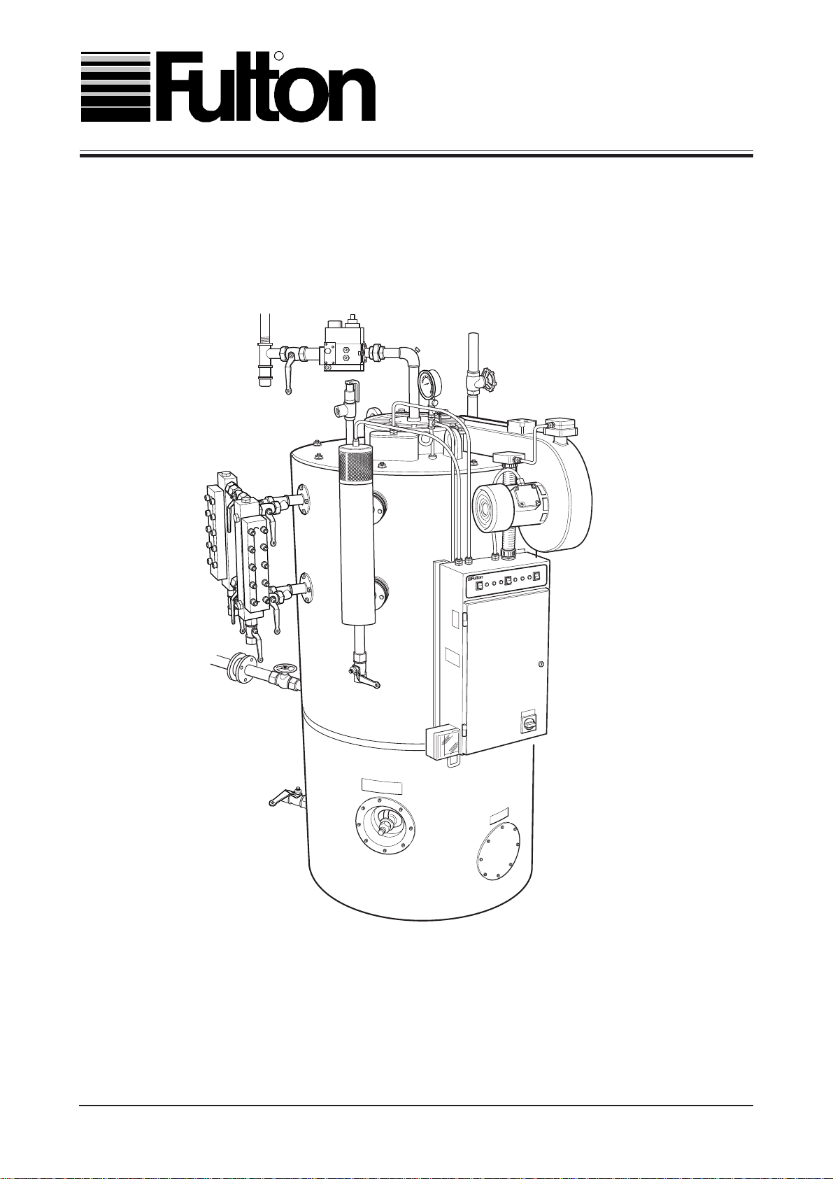
Fulton Boiler Works (Great Britain) Ltd.
OPERATOR, SERVICE
& P ARTS MANUAL
SERIES 'E' - GAS FIRED
STEAM BOILERS (6E - 60E)
GFSE-Std-0202
Page 2

WARNING
Steam Boilers are a potential hazard possibly
fatal if not properly maintained.
CAUTION
It is vitally important that the instructions given
in this manual are strictly adhered to.
Failure to carry out the daily, weekly, monthly and six monthly checks
could result in a drastic reduction in the life expectancy of the boiler.
NOTE
The Pressure system and Transportable Gas Containers Regulations 1989
Fulton Boilers fall within the scope of the Pressure Systems Examination Scheme and
Section 40 of the Health and Safety at Work Act, 1974.
Regular inspections are therefore required by a 'Competent Person' at intervals not exceeding
14 months.
The scope of the examination and the actual intervals between examinations is at the
discretion of the competent person.
It is the responsibility of the user to provide a written scheme of examination for those parts
of the system in which a defect may give rise to danger.
Instructions in this manual are provided for the safe operation and maintenance of the boiler
and do not cover periodic statutory inspections.
For further information contact:-
(a) SAFed
SAFETY ASSESSMENT FEDERATION Limited.
Nutmeg House,
60 Gainsford Street,
Butlers Wharf,
London, SE1 2NY
(b ) Health and Safety Executive local office.
(c) Your insurance company/broker
GFSE-Std-0499
Page 3

LIST OF CONTENTS
TITLE SECTION
INTRODUCTION 1
General 1.1
Technical Data 1.2
INSTALLATION 2
General 2.1
Siting 2.2
Ventilation 2.3
Flue Outlet 2.4
Water Supply 2.5
Blowdown Valves 2.6
Main Steam Valve 2.7
Steam Safety Valves 2.8
Water Gauge Set 2.9
Gas Supply 2.10
Electrical Requirements 2.11
Steam Pressure Gauge 2.12
Plumbing 2.15
Commissioning the Boiler 2.16
Cleaning the Steam Lines and Pressure Vessel 2.17
L.P. Supplement - Gas Supply - Propane/Butane 2.18
OPERATION 3
General 3.1
Boiler Controls 3.2
Control Panel - Indicator Lights 3.3
Filling the Boiler - All Models 3.4
Starting the Burner - All Models 3.5
Daily Checks 3.6
Pump Check 3.6.1
1st. Low Water Check 3.6.4
Overiding Low Water Check 3.6.5
Blowdown Procedures 3.7
Evaporation Checks 3.8
MAINTENANCE 4
General 4.1
Weekly 4.2
Monthly 4.3
Three Monthly 4.4
Six Monthly 4.5
GENERAL DATA 5
SPARE PARTS 6
GFSE-Std-0499
Page 4
SAFETY
The instructions provided for the operation and maintenance of the boiler MUST be observed.
Failure to do so could result in damage to the boiler and serious personal injury.
WARNING
It is the responsibility of the installer to ensure all
parts supplied with the boiler are fitted in a correct and
safe manner.
WARNING
Do not try to do repairs or any other maintenance
work you do not understand. Obtain a Service Manual
from Fulton or call a Fulton Service Engineer
WARNING
Understand the electrical circuit before connecting or
disconnecting an electrical component. A wrong
connection can cause injury and or damage.
WARNING
A defective boiler can injure you or others. Do not
operate a boiler which is defective or has missing
parts. Make sure that all maintenance procedures are
completed before using the boiler.
CAUTION
Obey all laws and local regulations which affect you
and your boiler.
WARNING
The installation of Gas appliances including the flue
system should only be carried out by Corgi Registered engineers.
CAUTION
HYDRAULIC TEST - RISK OF BRITTLE FRACTURE
Hydraulic testing requires specialist equipment and
is normally only required by engineering surveyors /
inspectors.The material the boiler is manufactured
from, has not been impact tested, as it is not a
requirement of BS2790 (boiler construction standard). In order to ensure the material / pressure vessel
does not suffer from brittle fracture, hydraulic testing
should not be carried out below 5OC.
WARNING
The importance of correct boiler water and feed water
cannot be over emphasised, see the relevant section
in this manual.
CAUTION
LOW FEED WATER TEMPERATURE
Low feed water temperature can result in thermal
shock to the boiler pressure vessel. Return the maximum amount of condensate and if necessary preheat the feed water. If in doubt consult FBW.
WARNING
Only qualified persons should be allowed to
operate and maintain the boiler and its equipment. Boilers should always be drained through an
approved Blowdown Vessel.
WARNING
Do not change the boiler fuel without consulting the
boiler manufacturer.
WARNING
Non-approved modifications can cause injury and
damage. Contact your Fulton dealer before modifying
the boiler.
WARNING
You can be injured if you use faulty lifting equipment.
Make sure the lifting equipment is in good condition.
Make sure that lifting tackle complies with all local
regulations and is suitable for the job
WARNING
Operating the boiler beyond its design limits can
damage the boiler, it can also be dangerous. Do not
operate the boiler outside its limits. Do not try to up
grade the boiler performance by unapproved modifications.
WARNING
DANGER FROM HOT SURFACES
Steam Boilers have high temperature surfaces, that if
touched may cause serious burns. Only competant
and qualified personnel should work on or in the
locality of a steam boiler and ancillary equipment.
Always ensure the working area and floor are clear of
potential hazards, work slowly and methodically.
WARNING
DANGER FROM INCOMPLETE COMBUSTION
The importance of correct burner adjustment to achive
low emissions, safe, clean and efficient combustion
is paramount. Poor combustion, where unburnt gas
forms carbon monoxide is both a health hazard, and
the potential risk to the boiler from overheating,
caused by re-burning of the unburnt gas in the
secondary flue passes.
GFSE-Std-0499
Page 5

TITLE FIG. NO.
Gas Fired Steam Boiler 1
General Arrangement 2
Typical Installation 3
Typical Flue Connection 3A
Water Gauge Set 4
Steam Pressure Gauge 5
Burner Electrode Settings 6
Commissioning the Boiler 7
Monobloc Gas Valve 9
L.P. Gas Train 10
Boiler Operation 11
Control Panel 6E/30E 12
Control Panel 40E/60E 13
Water Gauge Blowdown Sequence 14 & 14A
Fault Finding Check List 15
Boiler Maintenance 16
Handhole Assembly 17
Burner Assembly 18
Flue Cleaning 19
Boiler Dimensions 20
Level Controller - Type LC1 21
SPARE PARTS
See index in Spare Parts Section
GFSE-Std-0499
Page 6
1 1
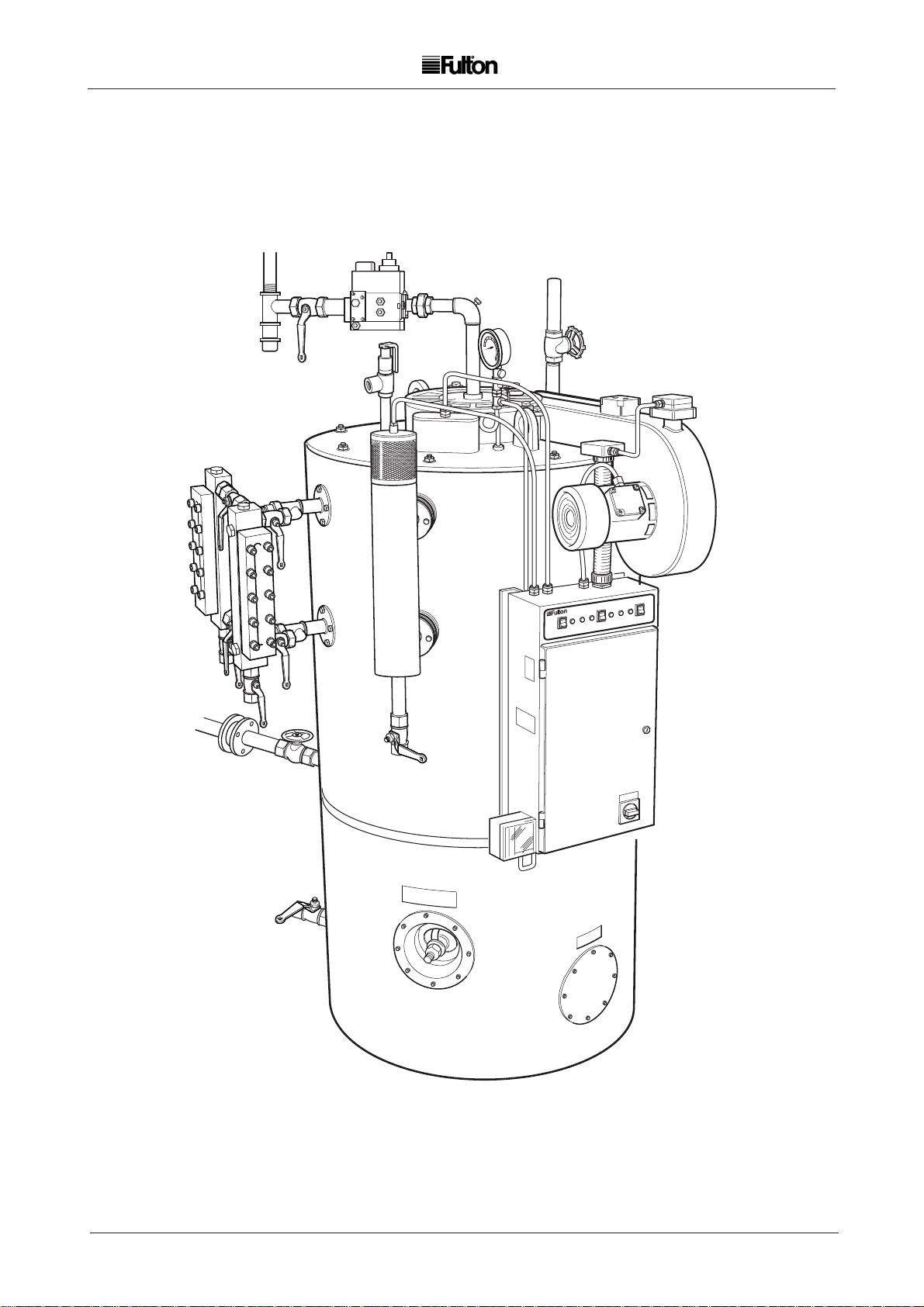
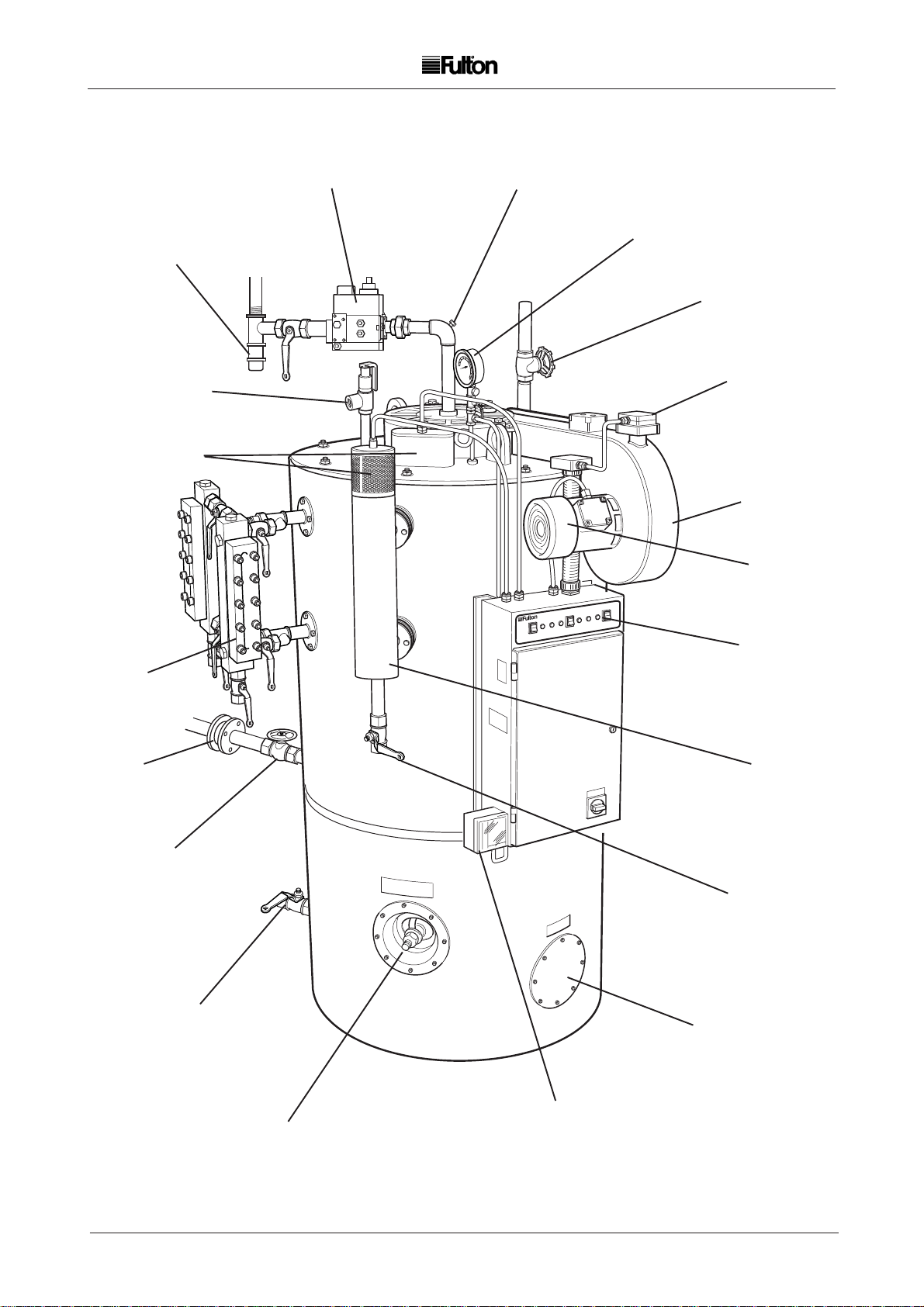
FIG.1 GAS FIRED STEAM BOILER
1
GFSE-Std-0499
Page 7
INTRODUCTION
SECTION 1
1.1 General (Fig. 1)
The Fulton Series E Gas Fired Steam Boiler is a vertical two pass boiler of simple and efficient design
and construction. Every care has been taken in the manufacture of the boiler to ensure that quality
and reliability standards are maintained. However, satisfactory performance can only be ensured if
the installation recommendations, operating routines and maintenance schedules laid out in this
manual are adhered to.
For Propane Boilers read Section 2.19 before proceeding.
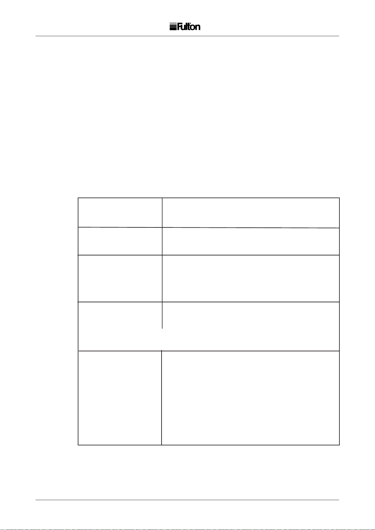
1.2 Technical Data
BOILER MODEL
1
6E 8E 10E 15E 20E 30E 40E 50E 60E
Performance
lb/h (F & A 100oC) 210 280 350 525 700 1050 1400 1750 2100
kg/h (F & A 100oC) 96 128 160 240 320 480 640 800 960
Firing Rates
Approx. BTU input (000) 255 340 424 637 849 1273 1360 2121 2546
Natural Gas 1035 BTU
cu.ft./h 246 328 410 615 820 1230 1700 2050 2461
cu.m/h 7 9.3 11.6 17.4 23.2 34.8 46.4 58.1 69.6
Electrical Requirements
FLC (400V, 3ph, 50Hz) amps 4.7 4.7 4.7 4. 7 4.9 4.9 6. 9 6 .9 8.6
FLC (230V, 1ph, 50Hz) amps 12.7 12.7 12.7 12.7 14.9 14.9 19.3 19.3 19.3
The full load current (flc) of the feed water pump motor can vary with the type and duty
requirements of the pump supplied. The figures quoted above are given as a guide only.
Miscellaneous
Water Content (Imp Gal) 13 15 20 33 64 14 1 2 0 4 20 4 2 2 3
Water Content (Litres) 59 68 91 15 0 291 6 40 92 7 92 7 1022
Approx. Net Weight (lb) 1540 1590 1785 2130 3135 4480 6728 6728 6944
Approx. Net Weight (kg) 700 720 810 965 1420 2030 3050 3050 3150
Nat. Gas Head
Pipe Size (in.) 1 1 1 1.25 1.25 1.5 2 2 2
Required Vertical 2060 2160 2210 2365 2440 2745 2845 2845 3000
Clearance (mm)
(Floor to Ceiling)
2
GFSE-Std-0499
Page 8
2 2
SCALE
TRAP
STEAM SAFETY
VALVE
WATER LEVEL
PROBES
MODULAR
GAS UNIT
PRESSURE
TEST POINT
STEAM
PRESSURE
GAUGE
MAIN STEAM
VALVE
AIR SAFETY
SWITCH
BLOWER
HOUSING
BURNER
MOTOR
WATER
GAUGE
CHECK
VALVE
STOP
VALVE
MAIN
BLOWDOWN
VALVE
CONTROL
PANEL
WATER
COLUMN
COLUMN
BLOWDOWN
VALVE
CLEAN OUT
DOOR
PRESSURE
HAND HOLE
FIG. 2 GENERAL ARRANGEMENT
3
GFSE-Std-0499
CONTROL
Page 9
2 2
INSTALLATION
SECTION 2
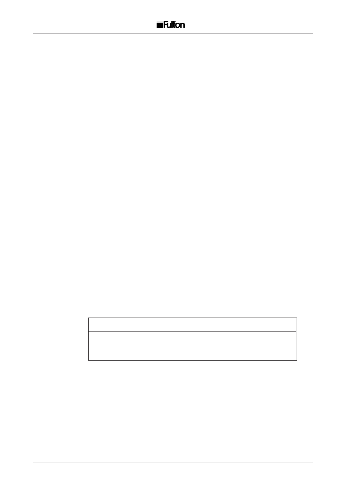
2.1 GENERAL (Figs. 2 and 3)
The installation of a Series E Gas Fired Steam Boiler should be carried out by competent personnel in
accordance with all relevant safety regulations. It is the responsibility of the installer to ensure that these
regulations are complied with.
The requirements and instructions contained in this Section generally relate to the boilers being installed
to operate on natural or manufactured gas. Where the boiler is to operate on L.P. Gas, special reference
should be made to Section 2.10 - Gas Supply, and Section 2.18 L.P. Gas Supply.
2.2 SITING
The boiler house should be sufficiently large to allow easy and safe access to all parts of the boiler for
operational and maintenance purposes. Reference should be made to Section 5 - General Data to
ascertain the relevant dimensions and special note taken of the required vertical clearance.
The flooring must be level, laid in a non-combustible material and be of sufficient strength to support the
boiler.
2.3 VENTILATION
Adequate fresh, clean air is necessary for safe and efficient combustion, and should be provided at high
and low level in accordance with BS 6644 1991.
Note:
(a) Ensure there is adequate ventilation in the boiler room. Lack of ventilation will create a high
temperature and cause control lockout.
(b) Do not keep exhaust fans running with windows, doors and vents closed, this will interfere
with the necessary boiler draught.
(c) Do not store chemicals such as perclorethylene in the boiler house, the fumes may damage
the boiler and flue and cause the burner to lock out on flame failure.
Boiler Model 6E 8E 10E 15E 20E 30E 40E 50E 60E
High Level (cm2) 305 360 420 560 700 980 1260 1540 1820
Low Level (cm2) 610 720 835 1115 1395 1960 2520 3085 3645
GFSE-Std-0499
4
Page 10
2 2
F01762
PIPE SAFETY VALVE
TO SAFE AREA,
FITTING
UNIONS AND DRAIN
STEAM SUPPLY
WATER
COLUMN
BLOWDOWN
VALVE
STOP
VALVE
DRAFT STABILISER
(WHERE FITTED)
CLEAN-OUT
DOOR
CHECK VALVE
MAIN BLOWDOWN
VALVE
STANDARD BOILER
OVERFLOW
CONDENSATE
RETURN
FEED PUMP
STRAINER
TRIM SUPPLIED
STAINLESS
STEEL
FEEDWATER
TANK
ISOLATING
VALVE
MAKE-UP SUPPLY
BLOWDOWN
SEPERATOR
PLUGGED
DRAIN
NOTE: A BREAK TANK MAY
BE REQUIRED - CHECK
THE LOCAL WATER
AUTHORITY BYE-LAWS
FIG. 3 TYPICAL INSTALLATION
5
GFSE-Std-0499
Page 11

2 2
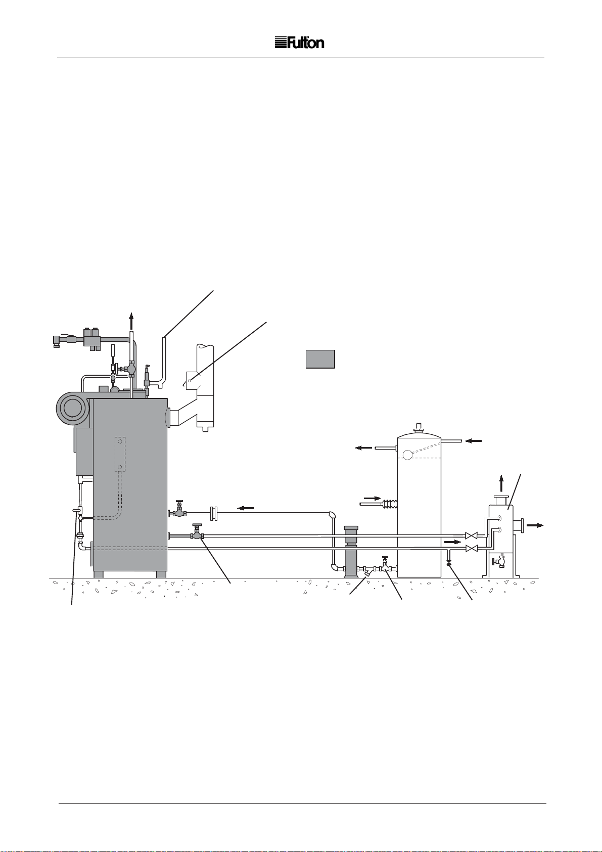
2.4 FLUE OUTLET
The boiler is supplied with a stainless steel flue spigot that should be inserted into the flue outlet in the
back of the boiler and secured with the three angle clips supplied loose in the trim box (see fig. 3A).
The height and type of flue will generally be subject to local planning regulations and approvals. The
following information is intended to provide assistance where the installation of a simple flue is required.
Where multi-boiler flues or difficulties are experienced, specialist advice should be obtained.
The flue diameter must be the same or larger than the flue flange provided with the boiler and the outlet
should be at least 2ft (610 mm) higher than the nearest ridge to avoid down draughts. Where a chimney
cowl is fitted, care should be taken to ensure that the cross sectional area of the outlet is equal to at least
1.5 times the cross sectional area of the flue, and that it is of the terminal cone type.
Note:
(a) If the flue layout is such that it may produce an excessive up-draught, a draught stabiliser
may be required.
(b) Avoid fitting 90deg. elbows whenever possible, if unavoidable compensate by increasing the
flue diameter.
(c) Ensure all pipework from the boiler to the main flue has a rising pitch of not less than 15deg.
2.5 WATER SUPPLY
The quality of the water used in the boiler will affect the life and performance of the boiler. It is strongly
recommended that a reputable water treatment concern is consulted prior to commissioning the boiler.
The following water conditions represent those which are considered essential in the boiler.
Total hardness of feedwater in terms of CaCo3 (mg/L) Max 2.
Caustic alkalinity of boiler water in terms of CaCo3 (mg/L) 300 ppm max.
Total dissolved solids in boiler water (mg/L) 2000 ppm max.
pH value of boiler water 9.5 to 11.5
Connect the feed water pump to the boiler with 1in. bore pipe and insert the stop valve and check valve
supplied. It is essential to protect the feedwater pump from damage by foreign matter. A strainer should
therefore be inserted in the pump suction pipework.
Note: 1. The boiler feedwater pump may contain an inhibitor and this should be flushed from the pump
prior to fitting the pump to the boiler. Failure to do so may result in water bounce or foaming
due to the inhibitor forming a seal in the boiler.
2. If the boiler is to be operated with little or no condensate return, consideration should be given
to pre-heating the feedwater. If in doubt consult Fulton Boiler Works.
3. The Feedwater inlet connection on some boilers is located on the left hand side of the boiler
below the sight glass assembly.
2.6 BLOWDOWN VALVES
There are three blowdown valves on the boiler (four if two water gauge sets are fitted), the main valve at
the rear of the boiler, the water column blowdown valve and the water gauge blowdown valve. All of these
valves must be connected to a blowdown receptacle of approved design. Regulations exist covering such
items and care must be taken to ensure compliance with these regulations. If in doubt regarding blowdown
arrangements, consult your Fulton agent.
2.7 MAIN STEAM VALVE
The main steam stop valve should be inserted in the steam line approximately 12in. (305 mm) from the
top of the boiler.
GFSE-Std-0499
6
Page 12
2 2
F02490
WORKING
POSITION
FIG. 3A TYPICAL FLUE CONNECTION
STEAM
BLOWDOWN
WATER
BLOWDOWN
F03200
F03190
BLOWDOWN
GAUGE GLASS
FIG 4 WATER GAUGE SET
7
GFSE-Std-0499
Page 13
2 2
2.8 STEAM SAFETY VALVES
Safety Valves are factory fitted and preset, they MUST NOT be adjusted. The discharge outlet
should be piped to a safe discharge point and the piping so arranged that any condensate trapped
in the pipework will drain away from the valve.
(a) The lift pressure is indicated on the safety valve. (Do not adjust).
(b) The safety valve fitted to the boiler is designed to prevent the boiler exceeding it's design
pressure.
(c) Any system connected to the boiler not capable of accepting boiler pressure must be
protected by a separate safety valve set to the required pressure.
WARNING
Factory fitted safety valves are pre-set to protect the boiler only
and must not be used protect any other items !
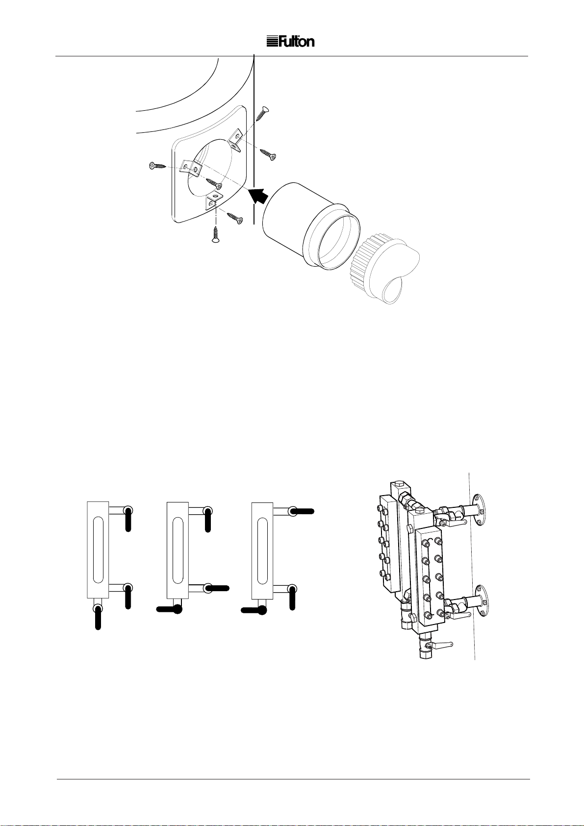
2.9 WATER GAUGE SET (The design may vary from that illustrated)
Numbers may vary due to individual countries regulations.
Boilers are normally supplied with two complete water gauge sets. These gauges should be fitted as
shown in main view Fig. 4. The water gauge glass blowdown cock should be connected to the auxiliary
blowdown line from the water column blowdown valve in soft copper tubing. The connection to the
gauge cock is 1/8 in. BSP for conventional gauge glasses and 3/8 in. for reflex type gauges, (all
connections female).
Mounting manifolds 'C' are only supplied for conventional tubular gauge glasses.
2.10 GAS SUPPLY
Verify that the burner is suitable for the type of gas being supplied. Ensure the piping from the meter
is the correct size, and that a gas cock is inserted in the line between the boiler and the meter. To
avoid pressure drops, eliminate all unnecessary bends and elbows in the pipework between the gas
meter and the boiler. A scale trap is provided on the gas train and should be used.
Burners suitable for operation on natural and manufactured gas are supplied with gas trains or a
modular gas head which are fitted with pressure regulating governors. No additional pressure
regulating devices should be required. A minimum pressure of 7 in. (17.5 mb) water column is
required at the gas train for natural gas installations and a minimum pressure of 5 in. (12.5 mb) water
column is required at the gas train for manufactured gas installations.
Burners arranged for operation on L.P. gas are supplied with gas trains which include a pressure
regulating governor. It is essential that the MAXIMUM pressure of the gas at the gas train does not
exceed 32 in. (80 mb) water column and does not fall below 20 in. (50 mb) water column. To obtain
these pressures a pressure regulating device or service governor must be fitted to the supply line
from the storage tank to the boiler gas train.
2.11 ELECTRICAL REQUIREMENTS
An individual wiring diagram for the boiler is located on the inside cover of the control box.
When referring to the electrical specification of the boiler, the reference number located on the rear
inside wall of the control box and the wiring diagram number should be quoted.
The audible alarm bells supplied are mounted on the side of the control panel, if not audible they
should be repositioned where they can be heard by a person competent to take the appropriate
action should the alarm be activated. Unless otherwise specified, the alarms supplied will be mains
voltage models. Unless otherwise specified all models are supplied with burner motors and feed
water pump motors arranged for operation on a three phase supply.
The power ratings and requirements are given in Section 1.2 - Technical Data.
GFSE-Std-0499
8
Page 14
2 2
STEAM PRESSURE
GAUGE
STEAM COCK
SYPHON
FIG. 5 STEAM PRESSURE GAUGE
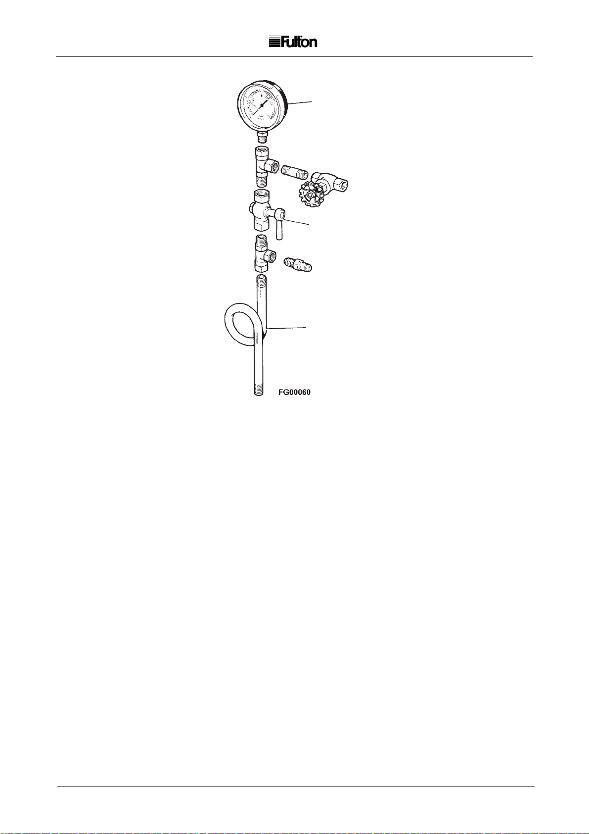
2.12 STEAM PRESSURE GAUGE (Fig. 5)
The steam pressure gauge assembly should be assembled in accordance with Fig. 5 using a
suitable sealant on all joints.
Screw the assembly into the top of the boiler and connect the copper tube from the control panel box to
the nipple provided on the assembly.
9
GFSE-Std-0499
Page 15

2 2
2.15 PLUMBING
(a ) Fit the check valve supplied, between the feedwater pump and the boiler feed water stop valve.
(b ) Ensure that the boiler is washed out after installation and before it is put into service.
(c) Conduct a feedwater analysis before operating the boiler.
2.16 COMMISSIONING THE BOILER (Fig. 7)
It is essential that the commissioning procedures listed below are carried out by a Fulton service
engineer who will have the necessary experience and testing equipment to ensure that the installation
is not only correct, but is operating safely and at optimum efficiency.
FLUE COMMISSIONING
Prior to initial firing of the boiler, the flue must be checked for leaks. This is done by BOTH of the following
methods:
Visual Inspection
Check joints between all flue sections for quality of seals. Where the flue passes through the
structure of the building use your judgement as to the integrity of this section of the flue.
Smoke Test
With the flue capped, the drain stabilizer pipe (if fitted) blanked and a smoke generator inserted
into the flue, their should be no smoke visible from the flue.
If either of these tests fail or at any time during boiler operation, there is doubt about the integrity of the flue,
shut down the boiler and contact Fulton Boiler Works Immediately.
Note: Flues that are designed to operate with positive pressure should be tested to the requirements of IGE/UP/
10 March 2001.
BOILER INSPECTION
(a ) Ensure the boiler has been washed out after installation.
Conduct a water analysis before operating the boiler.
Examine the probes in the water column and the boiler shell.
Replace any damaged probes.
(b ) If the burner is fitted with an ultraviolet sensor, remove the sensor and check for damage.
Remove the burner and check that the electrodes have not been damaged and that their setting
corresponds to the appropriate drawing (refer to Fig. 6).
(c) Check that the burner is the correct type for use with the gas being supplied.
MAIN GAS SUPPLY
ULTRA VIOLET
CELL
IGNITION
ELECTRODE
PRIMARY AIR
BLAST TUBE
297.4mm
3 mm MIN.
5 mm MAX.
12.7mm
FIG. 6 BURNER ELECTRODE SETTINGS
GFSE-Std-0499
50.8mm
10
Page 16

2 2
MODULAR
GAS UNIT
PRESSURE
TEST POINT
STEAM
PRESSURE
GAS COCK
SCALE
TRAP
STEAM SAFETY
VALVE
WATER
LEVEL
PROBES
GAUGE
MAIN STEAM
VALVE
AIR SAFETY
SWITCH
BLOWER
HOUSING
WATER
GAUGE
CHECK
VALVE
STOP
VALVE
MAIN
BLOWDOWN
VALVE
BURNER
MOTOR
CONTROL
PANEL
WATER
COLUMN
PRESSURE
CONTROL
CLEAN OUT
DOOR
11
HAND HOLE
FIG. 7 COMMISSIONING THE BOILER
COLUMN
BLOWDOWN
VALVE
GFSE-Std-0499
Page 17

2 2
(d) Ensure that all wiring connections are correct and that all terminal screws are tight.
(e) Insert a micro-ammeter into the meter jack (if fitted) on the burner programmer. This task should be
undertaken by a qualified service engineer.
(f) A barometric type draught stabiliser, if fitted in the flue, should be set for a draught of - 0.01 in. to 0.02
in. (0.025 mb to 0.05 mb) of water column pressure with the burner off.
(g) Open all the valves in the water feed line.
Switch on the feedwater pump motor and fill the boiler, see Section 3 - Operation.
The operation of the pump controls should be checked by using the boiler blowdown valve (located
at the rear of the boiler). When the water sight level gauge is reading half full, the pump will stop.
Open the boiler blowdown valve and slowly drain the boiler. When the water level falls below the
PUMP ON probe, the pump should start. If the pump does not start check the probe connections.
Close the boiler blowdown valve.
(h) After purging the gas lines of air, start the burner as detailed in Section 3 - Operation. Check the
readings on the micro-ammeter for the pilot and main flames, adjusting the primary air control to
obtain the maximum readings.
(j) Adjust the main air control gate to obtain a clean combustion.
(k) Observe the flame through the peephole between the electrodes and adjust the primary air
control so that the flame cannot be seen 'backing up' the blast tube.
(l) Check the operation of the low water safety controls as detailed in Section 3 - Operation.
(m) Adjust the steam pressure control to suit the boiler application. It should be borne in mind that boilers
are designed to operate most efficiently at their maximum operating pressure. When boilers are to
be operated below a pressure of 80 psi (5.5 bar) consideration should be given to the fitting of a
pressure reducing set. See 2.8 Safety Valve setting.
If the pressure control is fitted with a differential scale:
(i) Set the main scale to the maximum pressure required.
(ii) Set the differential scale to give the required pressure differential between the boiler cutting out
and restarting. If the pressure control has a fixed differential, i.e. no adjustable differential scale, set
the main scale to the maximum pressure required.
SETTING THE BURNER FOR LOW FIRE / HIGH FIRE, MODELS 50E AND 60E
The correct settings for low fire/high fire operation are obtained by making adjustments to the two stage
solenoid valve (Fig. 8) and the low fire steam pressure switch.
(a) Set the gas input to the boiler for correct input on high fire. This should be done where possible by
using the gas meter. Adjust the main air gate and top damper adjustment to obtain optimum
combustion conditions.
(b) Adjust the low fire steam pressure switch to cut out at approximately 5 psi below the setting of the
main steam pressure control (See Section 2.16 (m)).
(c) Adjust the two-stage solenoid valve to obtain a low fire gas input of approximately 80% of high fire.
Leave the air gate adjustments as for high fire.
(d) Refer to the adjusting procedure below on the two-stage solenoid valve.
GFSE-Std-0499
12
Page 18

2 2
MONOBLOC GAS VALVES (FIG. 9)
ADJUSTMENTS 6E - 30E (MBDLE 407/412 B07)
(With in built pilot bypass valve)
Pilot gas rate should be set to a maximum of 10% of the full fire gas throughput.
A
C
F
D
E
ADJUSTMENTS ACTION
A Main and Pilot Gas Governor. Turn clockwise to increase gas pressure. Range 4 - 20 mbar.
B Pilot gas range. Turn anticlockwise to increase and clockwise to decrease rate.
C First and second stage -
initial lift adjuster, main gas valve.
D Main gas throughput Slacken locking screw, turn fluted knob anticlockwise to
increase, clockwise to decrease.
E Gas supply test point
F Boiler side test point
ADJUSTMENTS 6E - 30E (MBDLE 407/412 BO1)
The Monoblock gas valve operates in two stages through two main shut-off valves:-
Stage 1. The first valve opens fully and the second valve opens slowly such that the
maximum gas flow rate during the start gas proving period does not exceed 30% of the full
firing rate.
Stage 2. The second valve is fully open.
NOTE: The time taken to open fully is set by the adjustment of the first and second stage initial lift adjuster.
A
B
B
E
F
D
ADJUSTMENTS ACTION
A Main and Pilot Gas Governor. Turn clockwise to increase gas pressure. Range 4 - 20 mbar.
B First and second stage -
initial lift adjuster, main gas valve.
C Main gas throughput Slacken locking screw, turn fluted knob anticlockwise
to increase, clockwise to decrease.
D Gas supply test point
E Boiler side test point
F Low gas pressure switch
13
GFSE-Std-0499
C
Page 19

2 2
MONOBLOC GAS VALVES (FIG. 9) continued.
ADJUSTMENTS 40E - 60E (MBZRDLE 415/420 BO1)
A
G
C
E
ADJUSTMENTS ACTION
A Main Gas Governor. Turn clockwise to increase gas pressure. Range 4 - 20 mbar.
B First and second stage -
initial lift adjuster, main gas valve.
C High flame throughput Slacken locking screw, turn fluted knob anticlockwise to
increase, clockwise to decrease.
D Low flame throughput. Turn fluted knob anticlockwise to increase,
clockwise to decrease.
E Gas supply test point
F Boiler side test point
G Low gas pressure switch
B
F
D
2.17 CLEANING STEAM LINES AND PRESSURE VESSEL
During the first week of boiler operation, clean all oil and dirt from the boiler, steam line and condensate
return line.
(a ) Disconnect the condensate return pipe adjacent to the condensate return tank.
(b ) Direct the returns to a floor drain or other safe discharge point and make safe.
(c) Leave in this position for one week to allow all impurities to flush through.
(d ) Drain the boiler completely each day.
(e ) After the week is completed, drain and flush the condensate return tank, removing all installation
sediment. Reconnect the condensate return pipe to the condensate return tank.
GFSE-Std-0499
14
Page 20

2
2
15
GFSE-Std-0499
Page 21

2 2
L.P. GAS
2.18 GAS SUPPLY - PROPANE / BUTANE
WARNING
Do not change the boiler fuel without
consulting the boiler manufacturer.
Note: LPG Boilers should be installed to the requirements of IGE/UP/10 March 2001
An L.P. gas boiler is similar in design to a natural gas boiler, the main differences are important and
must be taken into account when installing the boiler and ordering spare parts.
When installing an L.P. gas boiler, the feed from the bulk tank supply must be fitted with a supply
governor which is set to reduce the supply feed pressure to the boiler governor to 30 in. (80 mbar)
Water Column or less.
For PROPANE:-The boiler governor must be adjusted to give a firing pressure of 10 in. (25 mb) water
column at the test point provided at the elbow on the gas train.
For BUTANE:-The boiler governor must be adjusted to give a firing pressure of 8 in. (20 mb) water
column at the test point provided at the elbow on the gas train.
Gas Pressure Alarm Indicator Light
For L.P.G. applications the inlet pressure switch is used to protect the system from over pressure
and should be set at 100 mbar.
BALL VALVE
GOVERNOR
PILOT
GAS
PILOT
ORIFICE
TUBE
GAS START
VALVE
FIG. 10 L.P. GAS TRAIN
MONOBLOC ADJUSTMENTS LPG Boilers (MBZRDLE 405/412 BO1)
F
D
ADJUSTMENTS ACTION
A Main Gas Governor. Turn clockwise to increase gas pressure. Range 4 - 50 mbar.
B First and second stage -
initial lift adjuster, main gas valve.
C Main gas throughput Slacken locking screw, turn fluted knob anticlockwise
to increase, clockwise to decrease.
D Gas supply test point
E Boiler side test point
F High gas pressure switch
GAS STOP
VALVE
A
MAIN GAS
B
E
C
GFSE-Std-0499
16
Page 22

3 3
MODULAR
GAS UNIT
GAS COCK
STEAM
PRESSURE
GAUGE
MAIN STEAM
VALVE
WATER LEVEL
PROBES
WATER
GAUGE
CHECK
VALVE
STOP
VALVE
AIR SAFETY
SWITCH
MAIN
BLOWDOWN
VALVE
17
COLUMN
BLOWDOWN
VALVE
FIG. 11 BOILER OPERATION
GFSE-Std-0499
Page 23

3 3
OPERATION
SECTION 3
3.1 GENERAL
The following instructions are given for the guidance of the operator in the use of the Series 'E' gas fired
boiler and to provide adequate information to ensure that when the boiler is put into use it will be done safely
and without risk to health.
Where original equipment Service Manuals are supplied, they must be read and understood in conjunction
with this manual. All Warnings and Cautions must be observed.
3.2 BOILER CONTROLS
The following brief description of the controls used on the Series E gas fired boiler is intended to provide
the operator with a basic understanding of the operating principles, which is essential for the continued
efficient operation of the boiler.
Note: All the controls are of the ‘fail-safe’ type and are wired in series; failure of any one will automatically
shut down the boiler.
Low Water Relays and Feedwater Pump Relays. These relays operate in conjunction with probes
suspended in the boiler and water column to automatically maintain the level of water in the boiler
and to cut-off the burner should the water level fall to an unsafe level.
Steam Pressure Control(s). Located on the control panel box and connected to the steam pressure gauge
assembly by copper tube, the pressure regulator controls the on/off cycle of the burner, shutting the
burner off when maximum pressure is reached and switching it on when the steam pressure falls.
Burner Programmer. This is the main control in the panel box. The programmer in conjunction with a
sensing device ‘supervises’ the ignition sequence, proves the flame is satisfactory and finally
‘monitors’ the established flame. Should any fault occur, either during the ignition sequence or during
normal running, the programmer will immediately go to ‘lock-out’ and both main and pilot gas valves
will be closed.
Air Pressure Switch. Mounted on the burner scroll, this switch is operated by the pressure of air entering
the burner through the throat of the scroll. Lack of air, or insufficient pressure, will prevent the switch
completing the circuit thus preventing the burner from operating.
Gas Head Assembly. Consists of pilot and main gas supply lines, each line having a manual gas cock,
a governor and electrically powered gas valves. The governors maintain a constant pressure of gas
entering the burner and are adjustable. The electrically powered gas valves are controlled by the
burner programmer.
GFSE-Std-0499
18
Page 24

3 3
MODULAR
GAS UNIT
STEAM
PRESSURE
GAUGE
GAS COCK
WATER LEVEL
PROBES
WATER
GAUGE
CHECK
VALVE
MAIN STEAM
VALVE
AIR SAFETY
SWITCH
19
STOP
VALVE
COLUMN
BLOWDOWN
VALVE
MAIN
BLOWDOWN
VALVE
FIG.11 BOILER OPERATION
GFSE-Std-0499
Page 25

3 3
3.3 INDICATOR LIGHTS
Indicator lights are fitted to the control panel as an additional aid to the operator.
The meaning and operating sequence of these lights is as follows:
Start/Low Water Reset
This switch is used to start the boiler and to reset the low water alarm. When the switch is pressed
to initiate the start-up sequence, the low water alarm lamp also illuminates and the low water
audible alarm sounds. Keeping the switch depressed for approximately 2 seconds cancels the low
water alarm and initiates the burner start sequence.
Illumination of this switch and sounding of the audible alarm at any other time other than at switch
on indicates that the boiler has gone to a lock-out due to a low water condition. Once the water in
the boiler has been restored to a safe operating level, pressing the switch will reset the controls.
Circuit On. (Circuit Energised 40E - 60E) Indicates that power is being supplied to the control panel box.
1st. Low Water Alarm. This light will energise, when the boiler is switched on and the water level
is between 1st. low water and 2nd. low water. A light will illuminate and a pulsing alarm sound.
2nd low water. The 1st. low water light and alarm are replaced by the 2nd. low water light and
a continuous alarm.
The second alarm must be reset, the first alarm will be automatically reset by the return to normal
water level.
Ignition. Indicates that the ignition transformer has been energised. This light will only be
illuminated for approximately 5 - 10 seconds during the ignition sequence.
Gas Pressure Alarm. This light will illuminate whenever the gas is off, or below minimum inlet
pressure required by the European Standard for gas burners EN676.
This switch is factory set, normally to 10 mbar, and should not be adjusted after the boiler has
been commissioned.
Main Gas. This light illuminates when the Monoblock gas valve is energised.
Flame Failure / Reset.This switch will be illuminated when the burner has gone to a lock out
condition due to flame failure. The burner controller can be reset by pressing this switch.
Combustion Air. This light indicates that the burner motor contactor is energised.
ADDITIONAL INDICATOR LIGHTS ON MODELS 40J AND 60J
Low Flame. This light indicates that the burner is operating in the low flame mode.
High Flame. This light indicates that the burner is operating in the full firing mode.
PUMP CONTROL
Pump Override Switch. Fitted on the left side of the control panel, used to switch off the pump during
evaporation tests.
START
LOW WATER
RESET
LOW
WATER
ALARM
CIRCUIT
ON
COMBUSTION
PUMP ONLY
IGNITION
OFF OFF
AIR
PUMP & BOILER
FIG . 12 CONTROL PANEL 6E / 30E
GFSE-Std-0499
GAS
PRESSURE
ALARM
FLAME FAILURE
MAIN
GAS
RESET
20
Page 26

3 3
START
LOW WATER
RESET
LOW WATER
ALARM
COMBUSTION
AIR
CIRCUIT
ENERGISED
IGNITION
PUMP ONLY
OFF
PUMP & BOILER
OFF
GAS
PRESSURE
ALARM
MAIN
GAS
LOW
FLAME
HIGH
FLAME
FLAME FAILURE
RESET
FIG. 13 CONTROL PANEL 40E / 60E
3.4 FILLING THE BOILER - ALL MODELS
Carry out the following procedure on the initial start up of the boiler and on every subsequent occasion
when restarting the boiler after a shut down:
(a ) Ensure the main steam stop valve is OPEN.
(b ) Ensure the steam pressure gauge isolating valve is OPEN.
(c) Ensure all the valves in the main gas supply to the boiler are OPEN.
(d ) Ensure all the valves in the water feed line are OPEN.
(e ) Ensure the main boiler blowdown valve is CLOSED.
(f ) Ensure water level gauge isolating valve(s) is OPEN.
(g ) Ensure water level gauge blowdown valve(s) is CLOSED.
(h ) Ensure water column blowdown valve is CLOSED.
(i) Ensure the Burner and Pump switch is in the OFF position.
(j) Ensure all appropriate electrical isolators are switched ON.
(k) Ensure the pump override switch is switched OFF.
CAUTION
The feed pump seals are water cooled.
The pump must never be allowed to run whilst dry, irreparable damage may result.
Ensure the pump is fully primed before energising the motor.
(k) Press the control switch to the PUMP ONLY position.
Note: If the boiler water level is below its correct level, the feed water pump will operate. When the water
reaches the correct level (half way up the water level gauge sight glass), the pump will stop.
If the water level is above the top of the water level gauge sight glass, drain off until the level
is in the middle of the water level gauge sight glass.
21
GFSE-Std-0499
Page 27

3 3
3.5 STARTING THE BURNER
(a ) CLOSE the main steam stop valve.
(b ) Press the control switch to 'PUMP AND BOILER' position, the low water audible alarm will sound,
the low water reset and low water alarm lights will illuminate.
(c) Press the low water reset switch for two seconds maximum.
The alarms will stop, and the alarm lights extinguish.
The burner start sequence will commence.
(d ) After a maximum of one minute the burner should be firing, and the main gas light be ON.
(e ) When the boiler has achived the required (set) pressure, the main steam isolating valve should be
opened allowing steam to enter the system distribution pipework.
WARNING
The system should be raised to temperature slowly to allow
for expansion and to avoid thermal shock and water hammer.
This can be achived by one of two methods.
1. Crack open the main steam valve and allow the system to heat up slowly, (minimum
15 minuets) before fully opening the main steam valve.
2. Open the main steam valve when starting the boiler, allowing the boiler and system to heat
up together.
Note: This can lead to water logging of the steam lines until full pressure is achived.
3.6 DAILY OPERATING TESTS (3.6 - 3.7)
Visually inspect the steam and feed water pipework, valves and fittings for signs of leakage. If leaks are
suspected shut the system down and evacuate the system to atmospheric pressure before attempting to
repair the leaks. The following procedure should be carried out by a competent person to ensure the correct
functioning of the water level and low water safety controls. Where possible, the boiler should not be under
steam pressure during these tests.
Note: Ensure that the water level is maintained during the pressure build up. If any part of the equipment
is not operating correctly, the fault should be investigated before the boiler is used. Ensure that all
blowdown pipework is safe and discharged to a blowdown receptacle.
3.6.1. PUMP CHECK
With the burner firing and the pump not running, lower the water level in the boiler by opening the main
boiler blowdown valve.
As the water level falls, visible in the sight glass, and before the low water lock out position is reached
the water pump should start to run. When this happens close the main boiler blowdown valve. The water
pump should continue to run and re-fill the boiler to the correct level and stop.
GFSE-Std-0499
22
Page 28

3 3
3.6.4 First Low Water Level
(a) Ensure the following:
The burner is firing.
The water level is correct in the boiler.
The water pump is not running.
(b) Switch the pump OFF at the pump overide switch.
(c) OPEN the main blowdown valve.
(d) When the water level nears the bottom of the water level gauge sight glass, the low water alarm
should sound, the LOW WATER ALARM lamp should illuminate and the burner should stop firing.
When this happens, CLOSE the blowdown valve IMMEDIATELY.
(e) Switch the pump ON at the main pump overide switch. The pump should run and refill the boiler.
When the water level in the boiler rises above the first low water level, the LOW WATER
LEVEL lamp should extinguish, the audible alarm should silence and the burner start sequence
should commence automatically. The pump should run until the boiler water level is correct and then
stop.
3.6.5 Overriding Low Water Check
(a ) Ensure the following:
The burner is firing.
The water level is correct in the boiler.
The water pump is not running.
(b ) Switch the pump OFF at the pump override switch.
(c) OPEN the main blowdown valve.
(d ) When the water level nears the bottom of the water level gauge sight glass, the LOW WATER
ALARM lamp should illuminate, the low water audible alarm should sound and the burner should
stop firing.
(e ) Continue to blow down. As the water level falls nearer the bottom of the water level gauge sight
glass, the LOW WATER RESET switch should illuminate and the second audible low water alarm
should sound.
(f ) CLOSE the main blowdown valve and switch the pump ON at the pump override switch. The water
pump should now start to run and refill the boiler. Once filled to the correct level the water pump
should stop. The low water alarm should continue to sound, the LOW WATER RESET switch and
LOW WATER ALARM lamp should remain illuminated and the burner should NOT start.
(g ) When the water level in the boiler is correct, the burner can be restarted by depressing the LOW
WATER RESET switch for a maximum of 2 seconds.
1. The First and Overriding low water checks can be carried out in one operation to reduce the
blowdown time and possible interruption to the steam supply.
2. Where the water level tests are to be carried out at full pressure, evaporate the water down to
1st. low level as in 3.8, blowdown the boiler from 1st. to 2nd. low water.
The purpose of adopting this procedure is to prevent steam and water being expelled from the
blowdown vessel vent because of prolonged blowdown.
23
GFSE-Std-0499
Page 29

3 3
3.7 BLOWDOWN PROCEDURES (DAILY TESTS)
Keep the boiler, water gauge, water column and interconnecting pipework free from sludge and scale
buildup by blowing down in the following manner:
(a ) Start the boiler and generate not more than 10psi of steam (see note).
(b ) Shut off both the burner and the pump.
Boiler Blowdown
(a ) Fully OPEN the boiler main blowdown valve for not more than 10 seconds.
(b ) CLOSE the valve.
NOTE: Where high levels of suspended solids are produced, longer and/or more frequent
blowdown may be required.
Water Column Blowdown
NOTE: The water column contains the pump ON/OFF probe, which is not safety interlocked.
(a ) OPEN the ball valve in the water column, close after 5 seconds.
Water Gauge Blowdown
(a ) Blowdown the water gauge, set 1.
1. Open the gauge glass blowdown valve A
2. Close (for approx. 3 seconds) the top gauge valve B
3. Open valve B
4. Close (for approx. 3 seconds) the bottom gauge valve C
5. Open valve C
6. Close valve A
Repeat for gauge set 2
Open the blowdown valve D for 2 - 3 seconds, close valve D
On completion of the blowdown procedure ensure that all isolation valves are OPEN and all
blowdown valves CLOSED.
NOTE: Where a Boiler is operating continuously at steam pressure, advice should be taken from a
Fulton agent as to the appropriate blowdown procedure. (refer to 3.6.5. (g) 1 - 2).
Water Level Gauge
Set 2
WORKING
POSITION
STEAM
BLOWDOWN
WATER
BLOWDOWN
B
Water Level Gauge operating positions.
A
FIG. 14 LEVER TYPE - WATER GAUGE
F03200
GFSE-Std-0499
Water Level Gauge
Set 1
C
A
F03190
24
Page 30

3 3
3.8 EVAPORATION CHECKS
With the boiler running under normal load conditions, and the pump stopped having just completed
a refill cycle:
(a ) Ensure that the boiler water level is correct.
(b ) Switch the pump OFF at the pump override switch.
The water level in the boiler will lower through natural evaporation. When the level nears the bottom of
the water level gauge sight glass, the first low water alarm will sound, the LOW WATER ALARM lamp
will illuminate and the burner will shut down.
If it is required to check the second low water alarm, wait a further period for the LOW WATER RESET
switch to illuminate.
When the check is complete, proceed as follows:
(a ) Switch the pump ON at the pump override switch.
(b ) Press the LOW WATER RESET switch. The pump will start to refill the boiler.
If the pump starts to run at any time during the test then the test must be abandoned and re-started from
the beginning.
GFSE-Std-0499
Page 31

3 3
Burner will Flame Low Water Poor Boiler will not
not start Failure Alarm Combustion Maintain Pressure
Power Supply
Gas Supply
Refractories
Ignition Electrode
Pri Air Adjustment
Sec Air Adjustment
Transformer
Low Water Probes
U/V Cell
Low Water Safety Relay
Water Level Relay
Pressure Control
Draught
Steam Overload
Feedwater Pump
Burner Programmer
Burner Motor
Contam. Feedwater
Feedwater Too Hot
Dirty Flues
Air Switch
FIG. 15 FAULT FINDING
GFSE-Std-0499
26
Page 32

3 3
MAINTENANCE LOG
Date Action Remarks Sig.
27
GFSE-Std-0499
Page 33

4 4
MAINTENANCE
SECTION 4
4.1 GENERAL
To ensure the efficiency of the boiler, carry out the regular maintenance instructions detailed below.
If any fault is found during these operations contact your Fulton representative.
Note: It is essential that regular checks are made to ensure that scale build-up is not taking place
within the boiler. Such checks will ensure that water treatment being applied to the boiler feed
water is effective.
The lower hand hole doors should be removed after one month of operation and the interior of the boiler
thoroughly examined. If scale or sludge build up is observed, it should be removed and the water treatment
supplier advised.
New gaskets must be fitted every time a handhole door is removed.
Subsequent interior examinations should be carried out on a regular basis until satisfactory conditions are
observed. Thereafter, inspections should be carried out at three monthly intervals.
4.2 (a)
SAFETY VALVE
OUTLET
4.3 (d)
DISCONNECT BURNER
FROM GAS HEAD
4.3 (d)
REMOVE THE
BURNER
PLATE SCREWS
FIG. 16 BOILER MAINTENANCE
GFSE-Std-0499
F03230
28
Page 34

4 4
4.2 WEEKLY
WARNING
Ensure the fittings around the steam safety valve(s) are secure.
The safety valve will be very hot, do not operate the safety valve without protection.
(a) Make sure that the pipes from the safety valve outlet is not damaged and that it continues to a safe
blowdown point.
(b) In addition to carrying out the daily operating tests described in Section 3 - Operation, the water level
and safety cut-off controls should be tested under operating conditions by interrupting the water feed
supply.
To carry out this test, depress the feed pump interrupt switch to isolate the feedwater pump and lower the water
level in the boiler by evaporation. As the level of water falls, the burner should shut down and the alarm sound.
On completion of this test, switch off the pump interrupt switch and check that the water level is restored to normal.
4.3 MONTHLY (Weekly tests plus)
(a ) Blow down the boiler and water column completely.
(b ) Inspect the hand holes in the boiler. If any leakage is evident proceed as follows:
Use only Fulton genuine replacement parts.
(i) Using the special tee handle wrench, remove the handhole assembly.
(ii) Remove the old gasket and thoroughly clean the mating faces of the plate and boiler.
(iii) Fit the handhole assembly as follows:
1 Place the new gasket on the handhole plate and ensure that it is seating correctly.
Do not use any grease, lubricant or adhesive.
2 Position the plate in the boiler, set the crab and tighten the securing nut only sufficiently
to provide a snug fit. Verify the position of the plate in the boiler to ensure that there
is uniform space between the periphery of the door and the boiler inspection opening.
Tighten the nut hand tight only. Using the special wrench, tighten the nut a further
quarter of a turn. DO NOT OVERTIGHTEN.
(iv) If the gasket leaks as the pressure is building up, tighten the securing nut only sufficient to
stop the leakage.
(c) Inspect the flanged joint covering the rear inspection port in which the blowdown valve is fitted, if any
leakage is evident replace the gasket.
(d ) Clean the sight glass. If any leakage is evident, renew the gasket.
Note: Isolate the gas supply.
(e ) Disconnect the gas head from the burner by unscrewing the union. Remove the burner plate screws,
withdraw the burner assembly. Clean the ignition electrodes and reset. If an ultra -violet cell is fitted,
check that the lens is clean.
(f ) Check feedwater and boiler water quality.
29
GFSE-Std-0499
Page 35

4 4
HANDHOLE
COVER PLATE
GASKET
CRAB
FIG. 17 HANDHOLE
4.4 THREE MONTHLY (Monthly tests plus)
(a ) Drain and isolate the boiler.
(b ) Remove the lower handhole assemblies and inspect the interior of the pressure vessel for scale
and sludge build up.
(c) Remove the feedwater pipe from the top of the boiler. Check the pipes and out are clear and
free from debris.
GAS PRESSURE
TEST POINT
GAS TRAIN
CONNECTION POINT
ULTRA-VOILET
SENSOR
SECURING BOLTS
IGNITION
LEAD
IGNITION
ELECTRODE
BURNER UNIT
FIG 18 BURNER ASSEMBLY
30
GFSE-Std-0499
Page 36

4 4
4.5 SIX MONTHLY (Three monthly tests plus)
It should be noted that after a Fulton boiler has been in operation for several months, pieces of burned metal will be
found in the space at the bottom of the boiler. These pieces of metal are the remains of a light gauge metal form
which was used during manufacture for forming the boiler insulation. This is normal and does not affect the efficiency
or the life of the boiler in any way.
(a ) Remove the cover plates and clean-out door. Clean out the flue passes. When replacing the cover
plates and clean-out door, use furnace cement to ensure a tight seal, thus preventing the escape
of hot gases.
(b ) Apply a small quantity of oil to the bearings of the burner motor and the feed water pump motor.
(c) Drain and flush the feed water tank. Clean any filters in the tank, in the feed water line or in the feed
water pump.
(d ) Remove and clean the water probes, take care not to crack the porcelain. After replacement of the
probes, check the operation of the low water cutoff relay and of the feed water pump.
(e ) Remove the air gate and clean the fan.
(f ) Test the flue using the following procedure:
Visual inspection
Check joints between all flue sections for quality of seals. Where the flue passes through the
structure of the building use your judgement as to the integrity of this section of the flue.
Smoke test
With the flue capped and a smoke generator inserted into the flue, their should be no smoke
visible.
If either of these tests fail, shut down the boiler and contact Fulton Boiler Works immediately.
(g ) Check the burner combustion to ensure that excess air and carbon monoxide values are within normal
limits i.e. less than 30ppm.
CLEANING
THE FLUES
REMOVE THE CLEANOUT DOOR TO
THE FLUE PASSES AND TO THE
BOTTOM OF THE BOILER
31
FIG. 19 FLUE CLEANING
GFSE-Std-0499
Page 37
5 5
GENERAL DA TA
SECTION 5
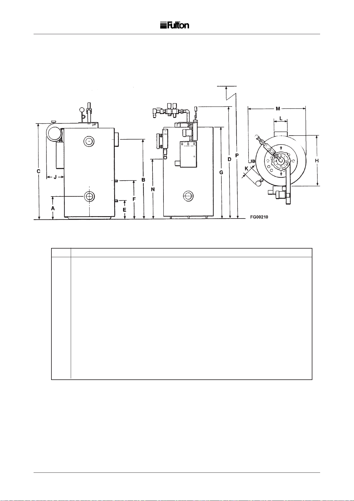
A B C D E F G H J K L MN P
6E 480 1295 1535 1960 380 840 1460 665 345 300 150 825 725 2000
8E 480 1395 1635 2060 380 840 1560 665 345 300 150 825 825 2100
10E 480 1445 1685 2110 380 840 1610 715 310 240 150 975 725 2150
15E 480 1570 1835 2260 380 840 1760 765 290 260 205 1025 875 2300
20E 510 1625 1955 2430 405 870 1840 985 415 250 255 1235 955 2500
30E 510 1850 2205 2690 405 870 2090 1175 420 250 305 1435 1205 2750
40E 510 1930 2290 2900 400 1095 2170 1390 470 250 305 1730 1285 2950
50E 510 1930 2290 2900 400 1095 2170 1390 470 250 305 1730 1285 2950
60E 510 2080 2440 3050 400 1095 2320 1390 470 250 305 1730 1435 3100
dimensions mm
FIG. 20 BOILER DIMENSIONS
Note:-
Standard Working Pressure 6E - 30E, 8.6bar. 40E - 60E, 10.34bar.
15mm Water Sample point located on Water Column if fitted.
Gas Train can rotate through 360O.
32
GFSE-Std-0499
Page 38

5 5
STANDARD TRIM ITEMS
Additions and Optional items should be requested when ordering the boiler
WARNING
It is the responsibility of the installer to ensure all parts supplied
with the boiler are fitted to the boiler in a correct and safe manor.
Standard Boiler Trim. Quantity
Main Steam Valve 1
Steam Safety Valve 1
Steam Pressure Gauge Assembly 1
Boiler Blowdown Valve 1
Water Level Gauge Set 2
Feedwater Check Valve 1
Feedwater Stop Valve 1
Flue Spigot 1
Audible Alarm 1 or 2*
Flue Brush 1
Tee Handle Wrench 1
Items marked * vary according to boiler specification.
BOILER TRIM 6 E 8E 10E 15E 20E 30 E 40E 50 E 60E
Steam Safety
Valve (Discharge side) (DN) 32 32 32 32 32 32 32 32 32
Steam Outlet
Valve (DN) 20 20 25 32 32 40 50 50 50
Feed Water Stop
Valves (DN) 25 25 25 25 25 25 25 25 25
Feed Water
Check Valve (DN) 25 25 25 25 25 25 25 25 25
Boiler Blowdown
Valves (DN) 20 20 20 20 25 25 25 25 25
Water Column
Blowdown Valves (DN) 20 20 20 20 20 20 20 20 20
Sight Glass
Blowdown Valve (DN) 666666666
GFSE-Std-0499
33
Page 39

5 5
MAINS
SENSING
INTERNAL
SCHEMATIC
INTERNAL BASE WIRING
Note: A common base is supplied for
type A & B controller bases. Links
must be fitted as per Fig. 21.
FIG. 21 TYPE LC1 LEVEL CONTROLLER
GFSE-Std-0499
34
Page 40

IMPORTANT
Recommended Water Conditions
It is very important that a strict water management program is followed to ensure trouble free boiler operation.
The following are recommended for feedwater and for boiler water.
FEEDWATER
pH Value 8.5 to 9.5 T ested at room temperature.
Hardness less than 2.0mg/kg In the form of CACO
Oil None
Suspended Solids None
Organic Matter Less than 5 ppm
Chloride Less than 50 ppm
BOILER WATER
Oxygen Scavenger,
Sodium Sulphide or Tannin 20 to 50 mg/kg Maximum
Phosphate 0 to 50 mg/kg, in the form of PO4
Total Alkalinity 1000 mg/kg Maximum
Caustic Alkalinity Less than 300 mg/kg as CACO
Chloride Less than 500 mg/kg
pH Value 9.5 - 11.5, tested at room temperature
Total Dissolved Solids 2000 ppm Maximum
Iron 1 mg/kg Maximum
Silica 180 mg/kg Maximum, in the form of SiO
Hardness Not detectable
Dissolved Oxygen None
Suspended Solids 100 mg/kg Maximum
3
3
2
mg/kg = Milligrams per Kilogram
CACO3 = Calcium Carbonate
PO4 = Phosphate
SiO2 = Silicon Dioxide
1 Grain hardness = 17.118 ppm therefore 70 ppm = 4.10 grains hardness.
For practical purposes mg/kg = ppm
It is critical that the boiler pH be alkaline (9 -1 1) whenever water is in the boiler .
Daily boiler blowdown is essential to help prevent formation of deposits and reduce
T otal Dissolved Solids (TDS).
Consult your Maintenance Manual for blowdown procedures.
Consult your Water Treatment specialist to establish the frequency and duration of
blowdown required to achive the required conditions.
Contamination from direct steam injection processes and leaks from indirect
systems must be avoided. Contamination in boiler feedwater / condensate will
result in unstable water levels foaming, carry-over and low water.
GFSE-Std-0499
Page 41
6 6
SPARE PARTS
SECTION 6
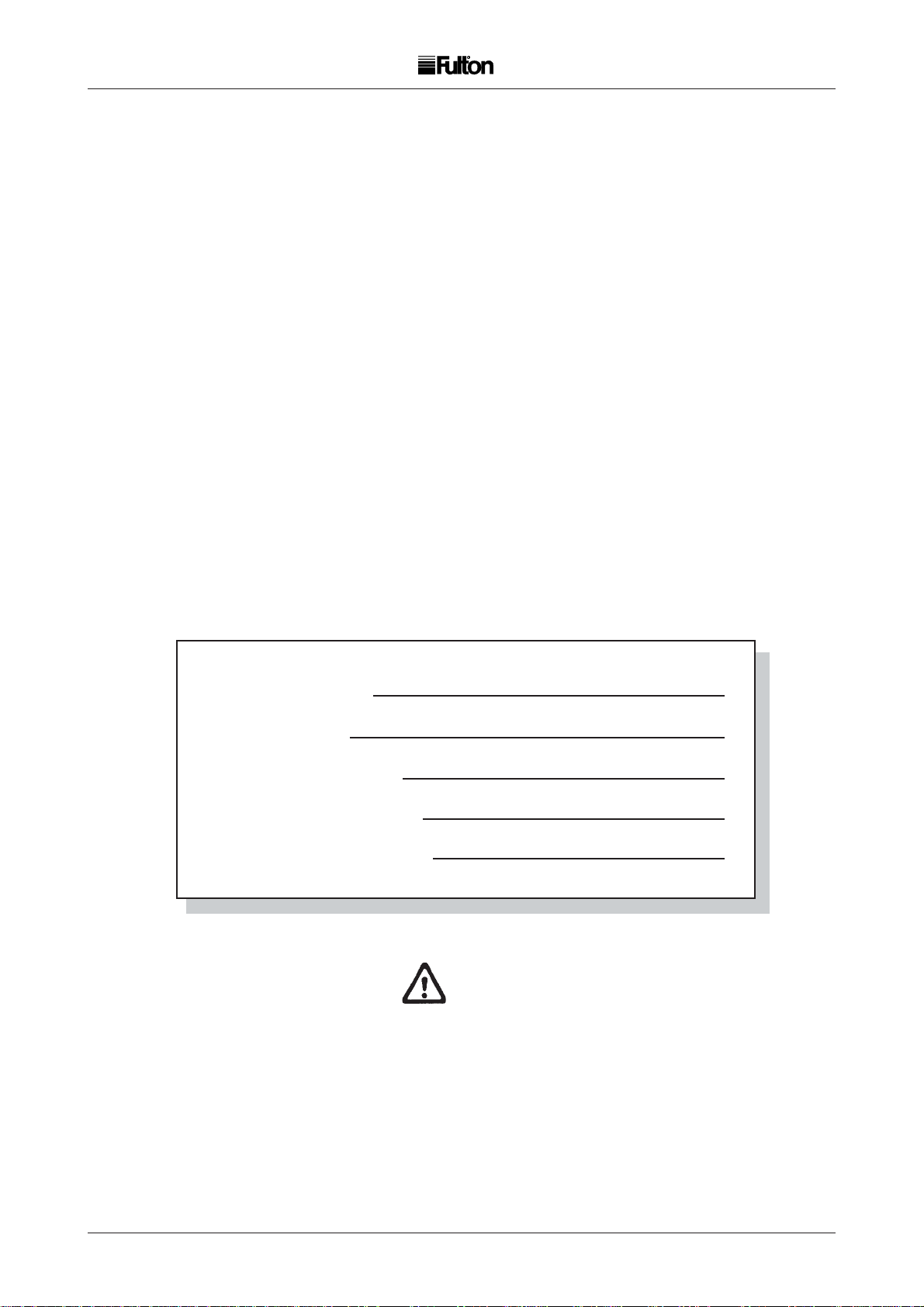
In order to ensure spare parts are correct, please complete the
details below and have them at hand when ordering parts or
making enquires regarding the boiler.
1. Boiler number
2. Boiler type
3. Type of fuel used
5. Wiring Diagram No.
6. Commissioning Date
WARNING
The type, size and lift pressure of the safety valve fitted to a boiler is specific to that boiler.
When ordering new safety valves it is important that, as well as the information requested
above, the following additional information is given:
Boiler design pressure (located on the boiler data plate).
Make and type (eg fig no.) of safety valve fitted.
36 36
GFSE-Std-0499
Page 42

GFSE-Std-0499
Page 43

Material & Workmanship Warranty
5 Year
Warranty
On the Fulton Boiler Pressure Vessel
Fulton Boiler Works (Great Britain) Ltd. will repair or replace FoB factory any Fulton
pressure vessel which within five (5) years of the date of delivery is found to be defective
in workmanship, or material, provided this equipment is operated and maintained by
the buyer for the purpose for which it was designed and in accordance with the
Manufacturer’s Handbook. This Warranty does not cover damage or failures that can
be attributed to corrosion, scale or dirt accumulation or to low water conditions. This
Warranty is good only in the United Kingdom of Great Britain and Northern Ireland.
This Warranty does not include labour or delivery charges of any kind.
Fulton Boiler Works, (Great Britain) Ltd.
General Warranty
The Fulton general Guarantee is given in lieu of
and in exclusion of any warranty expressed or
implied, statutory or otherwise, as to the state,
condition, performance, quality or fitness of the
goods. Save thereunder we shall be under no
obligation or liability of any kind to you in regard
to the goods. In the case of new goods
manufactured and supplied by us we will make
good any defect developing therein under proper
use within 12 months of delivery, provided that
after investigation in our sole discretion we are
satisfied that the defect arose from faulty design,
materials or workmanship and from no other
cause whatsoever.
Defective goods or parts must be returned to us
as soon as possible after discovery of the defect,
Costs of carriage and of detaching and
incorporating parts will be borne by you. ln all
cases at the termination of such 12 months all
liability on our part will cease.
No liability whatsoever is to be incurred by us in
respect of gauge or sight-glasses, packing glands
or electric motors orany goods or accessories not
of our manufacture. But so far as we are able, we
shall let you have the benefit of any guarantee or
warranty given to us in respect thereof.
GFSE-Std-0499
Page 44

Fulton Boiler Works (Great Britain) Ltd.
Broomhill Road
Bristol BS4 4TU
England
Telephone 01179 723 322
Fax: 0117 9723358
'e'-mail: uk-info@fulton.com
Web site: www.fulton.com
Fulton
FM 28400
GFSE-Std-0499
 Loading...