

Page 1

FCH 905 ID TS G DWK
PIANO DI COTTURA
INDUZIONE + ELETTROGAS
COOKING HOB INDUCTION +
ELECTROGAS
TABLES DE CUISSON
INDUCTION + ÉLECTROGAZ
EINBAUKOCHGERÄT
INDUKTIONSHERD + ELEKTRO
PLACA DE COCCIÓN
INDUCCIÓN + ELECTROGAS
MESAS DE ENCASTRAR
INDUÇÃO + ELECTROGÁS
IT
ISTRUZIONI PER L’INSTALLAZIONE E L’USO
GB
INSTRUCTIONS FOR INSTALLATION AND USE
FR
INSTRUCTIONS POUR L’INSTALLATION ET L’UTILISATION
DE
INSTALLATION UND GEBRAUCH
ES
INSTRUCCIONES PARA LA INSTALACIÓN Y USO
PT
INSTRUÇÕES DE INSTALAÇÃO E UTILIZAÇÃO
Page 2

Page 3
Caro Cliente,
sentitamente La ringraziamo e ci
congratuliamo per la scelta da Lei fatta.
Questo nuovo prodotto, accuratamente
progettato e costruito con materiali di
primissima qualità, è stato accuratamente
collaudato per poter soddisfare tutte le Sue
esigenze di una perfetta cottura.
La preghiamo pertanto di leggere e
rispettare le facili istruzioni che Le
permetteranno di raggiungere eccellenti
risultati sin dalla prima utilizzazione.
Con questo moderno apparecchio Le
formuliamo i nostri più vivi auguri.
IL COSTRUTTORE
Indice
Istruzioni per l’utente 4
Installazione, 4
Uso, 4
Manutenzione Gas/Elettrico, 5
Induzione, 6
Principio di funzionamento, 7
Utilizzazione, 8
Funzioni, 9
Manutenzione, 20
I
GB
FR
DE
ES
PT
Italiano
English
Français
Deutsch
Español
Português
I
Istruzioni per l’installatore 21
Installazione, 21
Posizionamento, 21
Collegamento gas, 23
Adattamento a diverso tipo di gas, 23
Collegamento elettrico, 24
QUESTO PRODOTTO È STATO CONCEPITO
PER UN IMPIEGO DI TIPO DOMESTICO.
IL COSTRUTTORE DECLINA OGNI
RESPONSABILITÀ NEL CASO DI EVENTUALI
DANNI A COSE O PERSONE DERIVANTI DA
UNA NON CORRETTA INSTALLAZIONE O DA
USO IMPROPRIO, ERRONEO O ASSURDO.
L’APPARECCHIO NON DEVE ESSERE
USATO DA PERSONE (COMPRESI BAMBINI)
3
CON RIDOTTE CAPACITÀ FISICHE,
SENSORIALI O MENTALI, O DA PERSONE
CHE MANCANO DELL’ESPERIENZA E DELLE
CONOSCENZE NECESSARIE SE NON SOTTO
LA SUPERVISIONE O DIETRO ISTRUZIONI
SULL’USO DELL’APPARECCHIO DA PARTE
DI UNA PERSONA RESPONSABILE PER
LA LORO SICUREZZA. I BAMBINI DEVONO
ESSERE CONTROLLATI PER ASSICURARSI
CHE NON GIOCHINO CON L’APPARECCHIO.
Page 4

Istruzioni per l’utente
Installazione
I
Tutte le operazioni relative all’installazione (allacciamento elettrico, allacciamento gas,
adattamento al tipo di gas, conseguenti regolazioni, ecc.) devono essere eseguite da
personale qualificato secondo le norme vigenti. Per le istruzioni specifiche vedi la parte
riservata all’installatore.
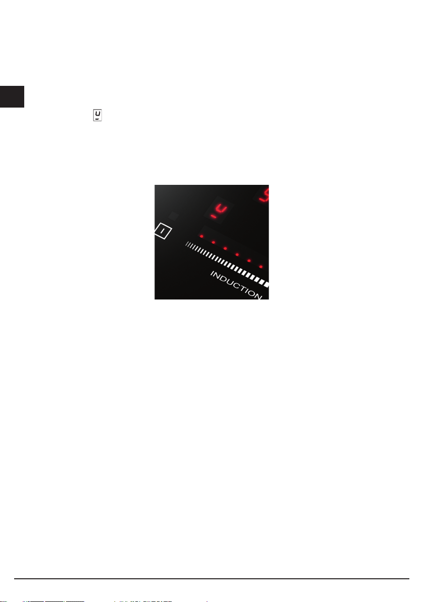
NON FISSARE INTENSAMENTE I LED E I DISPLAY.
Uso
Bruciatori gas
L’accensione del bruciatore avviene avvicinando una fiammella ai fori della parte superiore
dello stesso premendo e ruotando in senso antiorario la manopola corrispondente sino a
farne coincidere l’indice con la posizione di massimo.
Ad accensione avvenuta regolare la fiamma secondo la necessità.
La posizione di minimo si trova al termine delle rotazione antioraria.
Nei modelli con accensione automatica/simultanea (a una mano) è sufficiente agire come
sopra descritto sulla sola manopola corrispondente.
La scarica elettrica fra candelina e bruciatore dà luogo all’accensione del bruciatore
interessato. Ad accensione avvenuta rilasciare immediatamente il pulsante regolando la
fiamma secondo necessità.
L’accensione del bruciatore nei modelli con sicurezza termoelettrica avviene come
nei diversi casi sopra descritti tenendo premuta a fondo la manopola nella posizione di
massimo per circa 3/5 secondi.
Nel rilasciare la manopola assicurarsi che il bruciatore rimanga acceso.
N.B.
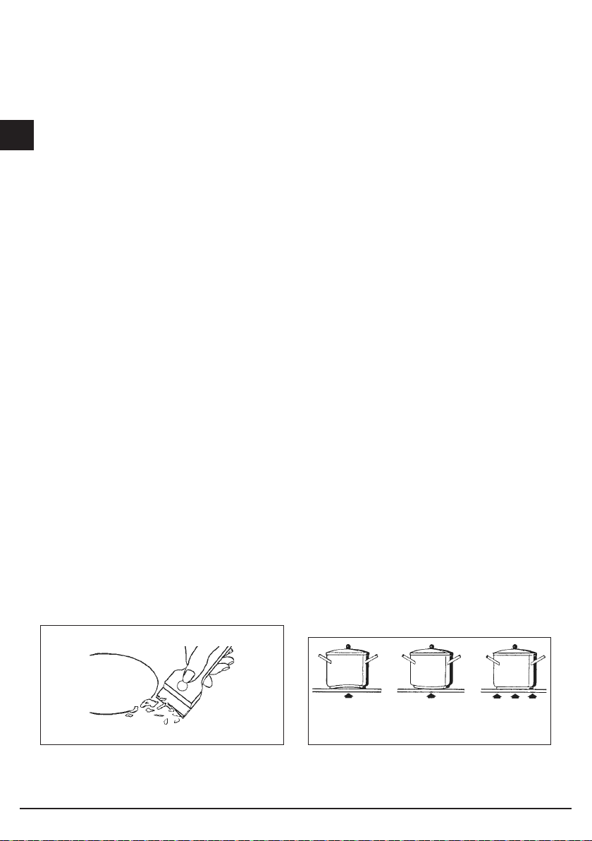
- Si consiglia di usare pentole di diametro adatto ai bruciatori evitando che la fiamma al
massimo fuoriesca dal fondo delle stesse;
- non lasciare pentole vuote sul fuoco acceso;
- sui piani Crystal non usare accessori di cottura alla griglia.
Al termine della cottura è buona norma provvedere anche alla chiusura del rubinetto
principale del condotto e/o della bombola.
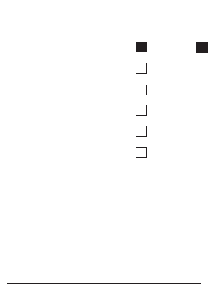
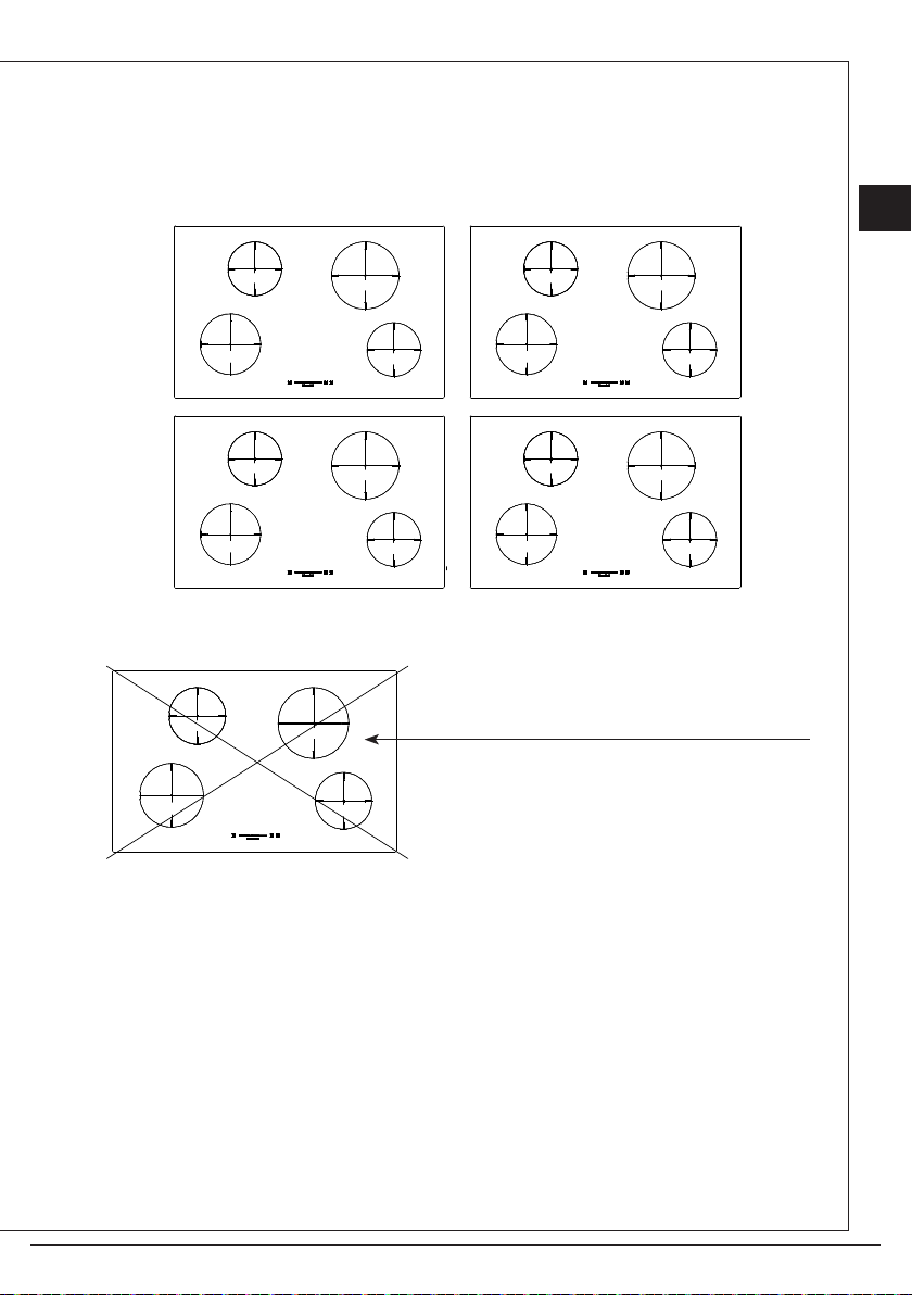
Modelli DWK
I modelli SH 905 ID G DWK e SH 905 ID G DWK sono dotati di un bruciatore Dual Wok. E’
possibile accendere la fiamma centrale (F1) ruotando e premendo la manopola in senso
orario, oppure accendere tutto il bruciatore (F2), come indicato in figura qui sotto.
4
Page 5
I
F1
F2
F2
F1
F2
F1
Importante
GAS PROTEKT
Nei piani con sicurezza termoelettrica (Gas Protekt) non azionare l’accensione oltre 15
secondi.
Se dopo 15 secondi il bruciatore non si è acceso, aprire la porta del locale e attendere
almeno un minuto prima di ritentare.
GAS
wok Ø 20-32
*con griglia di riduzione
Fig. 1
Manutenzione Gas/Elettrico
Prima di ogni operazione disinserire elettricamente l’apparecchiatura. Per una maggiore
durata dell’apparecchiatura è indispensabile eseguire periodicamente un’accurata pulizia
generale tenendo presente quanto segue:
• le parti in vetro, acciaio e/o smaltate devono essere pulite con prodotti idonei (reperibili
in commercio) non abrasivi o corrosivi. Evitare prodotti a base di cloro (varechina, ecc.);
• evitare di lasciare sul piano lavoro sostanze acide o alcaline (aceto, sale, succo di limone,
ecc.);
• gli sparti fiamma ed i coperchietti (parti mobili del bruciatore) vanno frequentemente lavati
con acqua bollente e detersivo avendo cura di togliere ogni eventuale incrostazione,
asciugati accuratamente, controllare che nessuno dei fori dello spartifiamma risulti
otturato anche parzialmente;
• le piastre elettriche si puliscono con uno strofinaccio umido e si ungono leggermente con
olio lubrificante quando sono ancora tiepide;
• le griglie inox del piano di lavoro dopo essere state riscaldate assumono una colorazione
5
Page 6
bluastra che non ne deteriora la qualità. Per riportarle all’aspetto originale usare un
I
prodotto leggermente abrasivo.
N.B. - L’eventuale lubrificazione dei rubinetti deve essere eseguita da personale qualificato
al quale è bene rivolgersi in caso di anomalie di funzionamento. Controllare periodicamente
lo stato di conservazione del tubo flessibile di alimentazione gas. In caso di perdite
richiedere l’immediato intervento del personale qualificato per la sostituzione.
NON UTILIZZARE PULITORI A VAPORE
Induzione
Il riscaldamento per induzione è la forma più efficiente, disponibile, per cucinare.
Il calore viene prodotto, con un campo elettromagnetico, direttamente sul fondo della
pentola o padella utilizzata. La superficie non coinvolta nel contatto rimane pressoché
fredda; una volta terminata la cottura e rimosso il contenitore non rimane calore residuo.
Efficiente perché non spreca energia per dispersione, come i bruciatori a gas, dal 30 al
50% più rapida dei normali piani con tecnologia HGL, consente risparmi energetici fino al
25%.
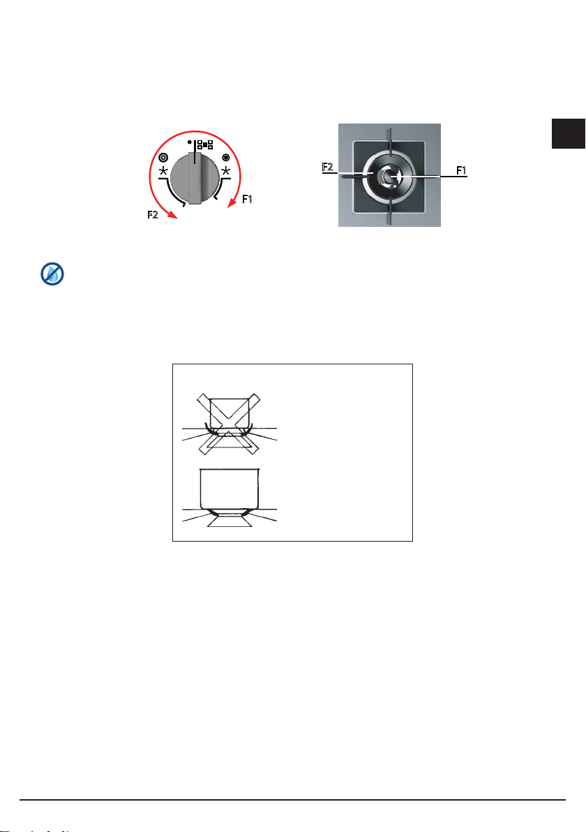
In presenza di trabocco di liquido dal contenitore non si attacca alla superficie del piano
in quanto è tiepido.
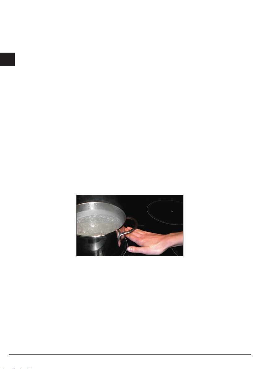
LPC (Sistema di potenza limitata)
L’induzione è una tecnologia utile, con LPC diventa anche fruibile per le nostre abitazioni.
Un sistema intelligente che riesce a distribuire la potenza delle varie zone per consentirne
un uso molteplice o alternato ma sempre mantenendo la massima potenza richiesta sotto
i 3kW totali di consumo.
Attenzione: le modifiche al sistema di potenza limitata devono essere eseguite solo
dall’istallatore.
Il costruttore declina ogni resposabilità.
6
Page 7
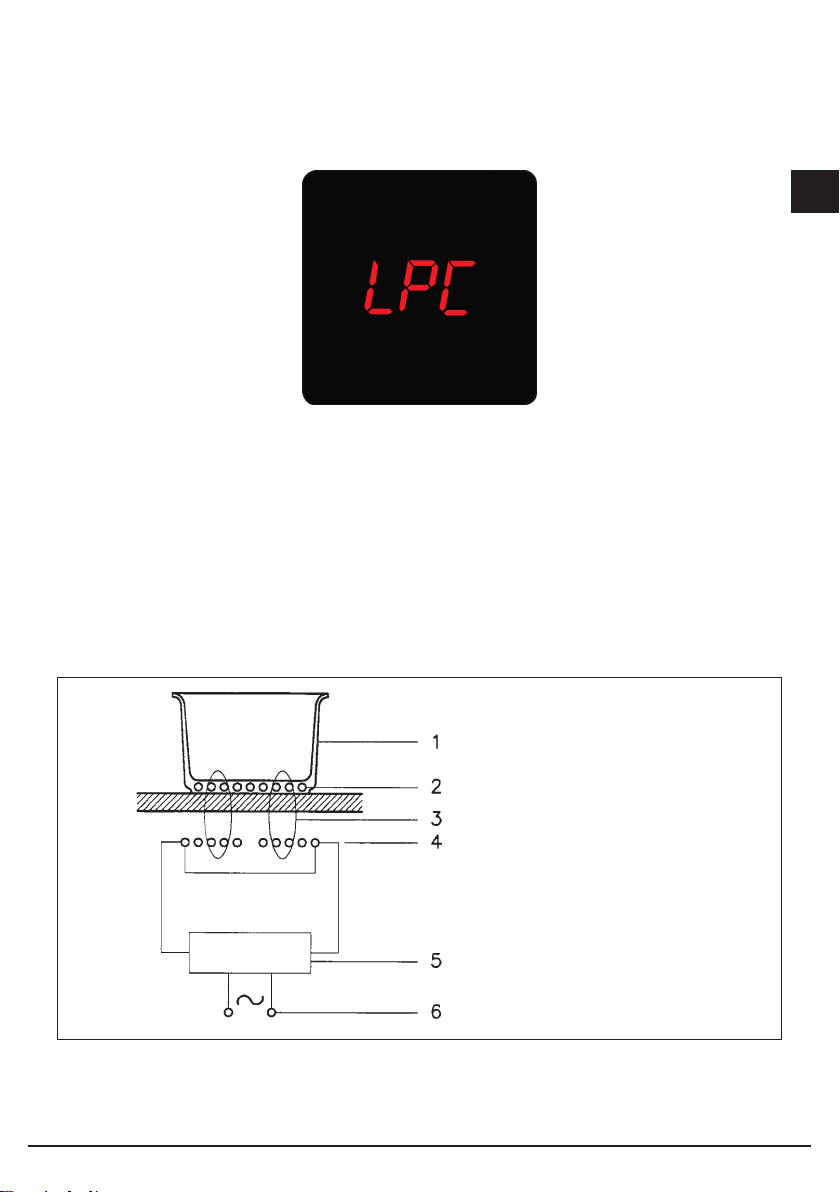
Principio di funzionamento
E’ basato sulle proprieta elettromagnetiche della maggior parte dei recipienti per la cottura.
Il circuito elettronico governa il funzionamento della bobina (induttore) creante un campo
magnetico.
Il calore e trasmesso dallo stesso recipiente al cibo.
La cottura avviene come sotto descritto.
- minima dispersione (alto rendimento);
- il ritiro della pentola (basta il solo sollevamento) provoca automaticamente l’arresto del
sistema;
- il sistema elettronico permette la massima flessibilita e finezza di regolazione.
1 - Recipiente
2 - Corrente indotta
3 - Campo magnetico
4 - Induttore
5 - Circuito elettronico
6 - Alimentazione elettrica
I
Fig. 2
7
Page 8
Utilizzazione
I
Per prima cosa posizionare la pentola nella zona di cottura prescelta. La mancanza della
pentola display non consente l’avvio del sistema.
Rilevamento pentola
Una certezza che contraddistingue l’utilizzo consapevole della tecnologia a favore del
consumatore
Installazione
Tutte le operazioni relative all’installazione (allacciamento elettrico) devono essere eseguite
da personale qualificato secondo le norme vigenti.
Per le istruzioni specifiche vedi la parte riservata all’installatore.
Uso
Tasti a sfioramento
Tutte le operazioni possono essere compiute tramite tasti a sfioramento (sensori di tipo
capacitivo) posti sulla faccia frontale della scheda; ad ogni tasto corrisponde un display.
Ogni attività viene confermata da un segnale acustico.
8
Page 9
I
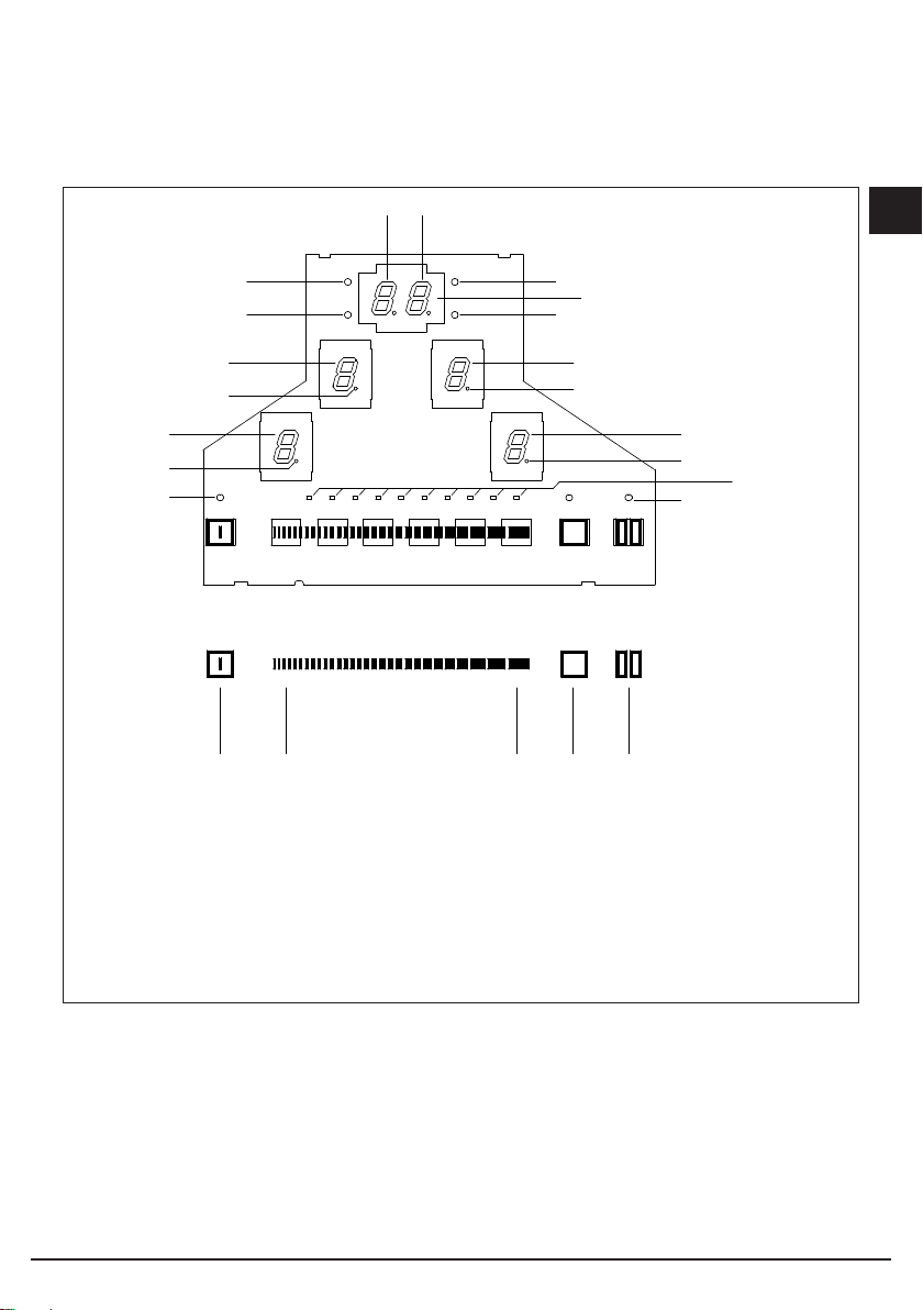
1 Accensione / Spegnimento ON/OFF
2 Area Slider +
3 Area Slider 4 Power Booster (P)
5 Timer
6 Display Valore Impostato
7A Display Timer
P
P
7B Display Timer
8 Spia Pausa
9 Spie Timer
10 Punto Decimale zona cottura
11 Spia accensione
12 Striscia luminosa led
13 Pausa
Fig. 3
Funzioni
Accensione/spegnimento del Touch Control
Dopo l’alimentazione, il touch richiede circa 1 secondo prima di essere pronto al
funzionamento. Dopo il reset tutti i displays e i LED lampeggiano per ca. 1 secondo. Passato
questo tempo tutti i display e i LED si spengono e il touch è in posizione di stand-by.
Il touch può essere acceso azionando il tasto di alimentazione. I display delle zone cottura
mostrano uno “0”. Se una zona cottura “scotta”, il display mostra “H” invece di “0’’. Il punto
in basso a destra su tutti i display dei punti cottura lampeggia ad intervalli di un secondo per
indicare che al momento non è stata selezionata alcuna zona cottura. Dopo l’accensione il
9
Page 10

touch rimane attivo per 20 secondi. Se non si seleziona né una zona cottura né il timer il
I
touch ritorna nello stato di stand-by automaticamente.
Il touch si accende esclusivamente azionando il tasto di alimentazione da solo. La pressione
del tasto di alimentazione in concomitanza con altri tasti non produce alcun effetto e il touch
rimane in standby. Se la sicurezza per bambini è attiva durante l’accensione, tutti i display
delle zone cottura mostrano “L”, (locked/bloccato).
Se le zone cottura “scottano” i display mostreranno “L” ed “H” (hot/ caldo) alternativamente.
Il touch control può essere spento in qualsiasi momento azionando il tasto di alimentazione.
Questo è valido anche se il comando è stato bloccato con la sicurezza bambini. Il tasto di
alimentazione ha sempre priorità maggiore nella funzione di spegnimento.
Spegnimento automatico
Una volta acceso, il touch si spegne automaticamente dopo 20 secondi di inattività. Dopo la
selezione di una zona cottura il tempo di spegnimento automatico si suddivide in 10 secondi
dopo il quale viene deselezionata la zona e, 10 secondi dopo, il touch si spegne.
Accensione/spegnimento della zona di cottura
Con il Touch Control allo stato acceso, è possibile selezionare una zona di cottura toccando il
display dedicato (6). Il display corrispondente passa a visualizzare il puntino fisso sul display e
“0” anziché “H” - in caso di zona di cottura bollente. Sui display di tutte le altre zone di cottura
il puntino scompare.
A questo punto è possibile impostare un livello di cottura utilizzando l’area Slider. In tal modo
si attiva la zona di cottura corrispondente. I valori di finecorsa sono “9” (lato destro) e “0” (lato
sinistro).
Spegnimento di una singola zona di cottura:
È possibile spegnere una singola zona di cottura selezionando un livello di cottura [0]. In
presenza di una spia di avvertimento di zone di cottura bollenti [H], tale segnalazione viene
visualizzata alternatamente a [0] e simultaneamente al puntino sul display. Una volta spento
il Touch Control, il display rimane spento o viene visualizzato il simbolo [H] come segnale di
avvertimento di zona di cottura bollente.
Spegnimento di tutte le zone cottura:
Lo spegnimento immediato di tutte le zone può essere ottenuto in qualsiasi momento tramite
il pulsante di alimentazione. In modalità stand-by una “H” appare per tutte le zone cottura
che “scottano”. Tutti gli altri display saranno spenti.
Livello di potenza
La potenza della zona cottura può essere impostata in 9 livelli che sono indicati dai simboli
da “1” a “9” tramite i display a LED di sette segmenti.
10
Page 11
touch control intensità calore
1 tenue
2-3 dolce
4 lento
5-6 medio
7-8 forte
9 vivo
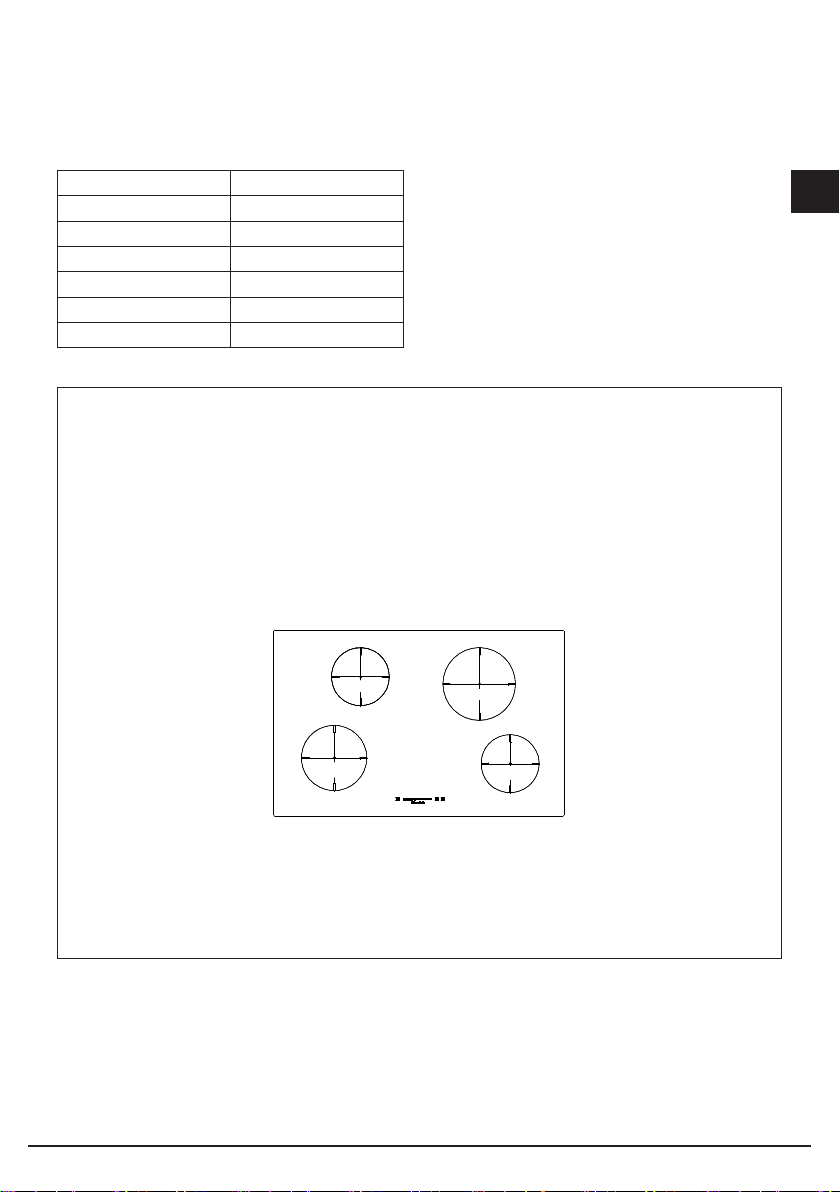
A: ZONA COTTURA INDUZIONE ø160 LIVELLO 9 = 1200W CIRCA, P = 1400 W
SOGLIA MINIMA DI PARTENZA 700W
B: ZONA COTTURA INDUZIONE ø180 LIVELLO 9 = 1400 W CIRCA, P = 2000 W
SOGLIA MINIMA DI PARTENZA 1200W
C: ZONA COTTURA INDUZIONE ø200 LIVELLO 9 = 2300 W CIRCA , P = 3000 W
SOGLIA MINIMA DI PARTENZA 1200W
I
A ø160
B ø180
C ø200
A ø160
LA DISPOSIZIONE DEGLI INDUTTORI, RICONOSCIBILE IN BASE ALLE
DIMENSIONI ø160-ø180-ø200, PUO’ VARIARE MA IL COMPORTAMENTO
GESTITO CON IL LIMITATORE (3.3kW) RIMANE IDENTICO
Fig. 4
11
Page 12
C ø200
A ø160
B ø180
9
0
0
P
0
8
P
0
8
0
8
9
A ø160
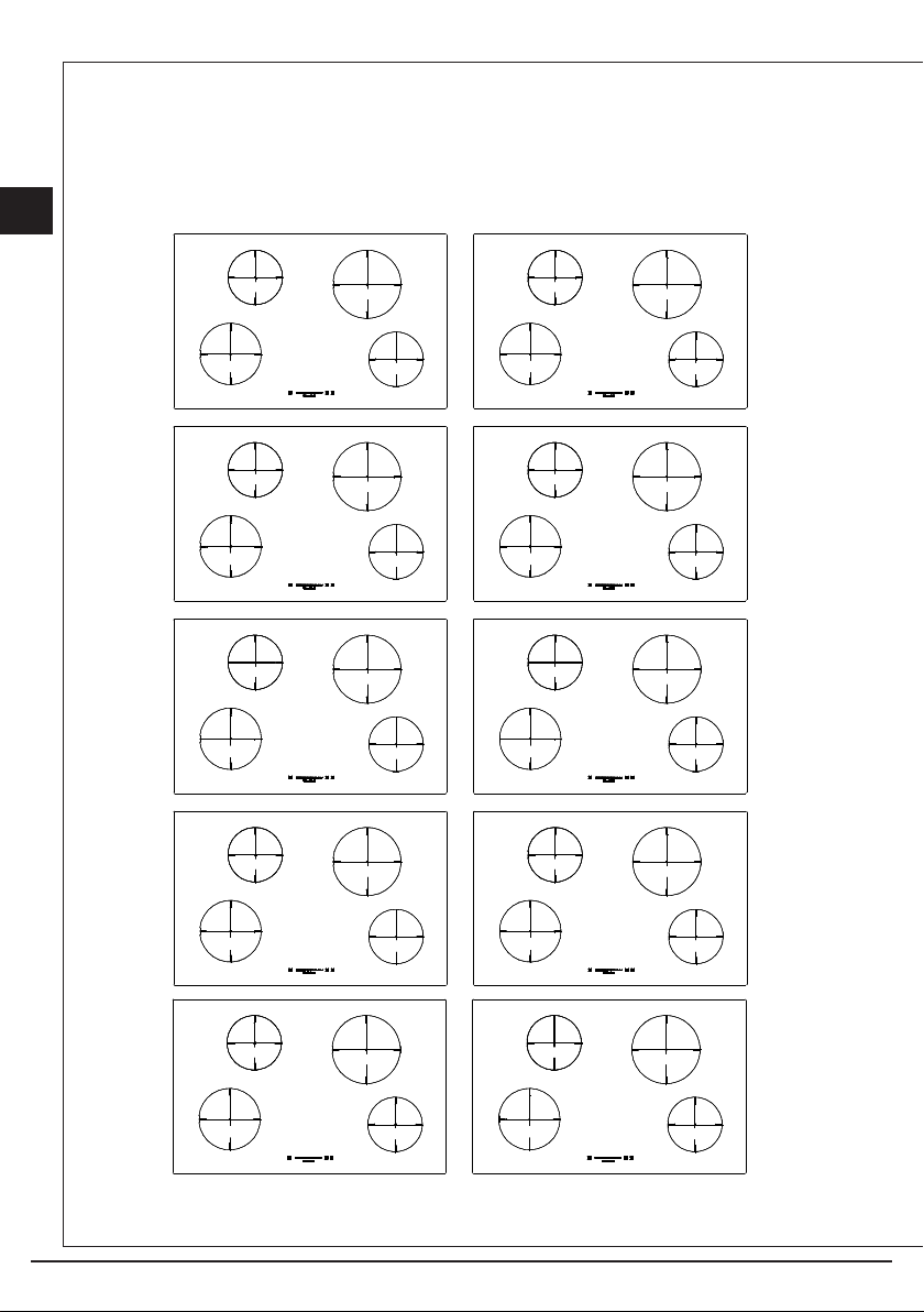
ALCUNI ESEMPI DI LIVELLI MASSIMI ACCETTATI DAL TOUCH
DELL’INDUZIONE CON LIMITATORE INSERITO (3.3kW) CON GLI
ELEMENTI INDUTTIVI RAPPRESENTATI.
I
0
0
P
9
7
0
8
P
0
7
8
0
0
P
P
0
0
9
8
0
0
P
0
P
7
9
7
0
0
P
8
0
9
8
9
P
8
0
0
12
Page 13
9
0
0
P
0
0
9
P
C ø200
A ø160
B ø180
0
P
0
0
P
0
P
0
9
0
0
P
0
P
9
P
0
0
9
0
8
P
0
P
7
7
0
9
7
8
0
8
0
8
9
8
8
8
0
8
7
8
0
A ø160
I
P
0
8
9
1
1
8
0
0
8
1
1
7
8
9
8
Non possibile con limitatore di
potenza inserito
0
P
0
8
Possono funzionare tutte le zone cottura contemporaneamente anche al livello
massimo sbloccando il limitatore di potenza (funzionamento a 7.1 kW) in tal caso
accertarsi che l’impianto elettrico dove è installato il piano sia opportunamente
dimensionato e che il cavo sia del tipo H05V2V2-F S 2.5mm²
N.B. L’induzione viene prodotta con limitatore inserito. L’elettronica gestirà la
potenza fino alla soglia limite di 3.3 kW Per rispettare questo parametro a seconda
di quale induttore si è acceso verrà data la possibilità o meno di accendere altre
zone cottura. Un doppio bip segnalerà se si stà tentando di superare tale limite.
13
Fig. 5
Page 14
Funzione di riscaldamento automatico
I
Quando la funzione di riscaldamento automatico è attivata , la potenza della zona cottura
è al 100% per un determinato periodo di riscaldamento che dipende dal livello di potenza
selezionato. Alla fine del tempo di riscaldamento il touch ritorna al livello di potenza
preselezionato.
Inizio del processo di riscaldamento automatico:
– Il touch è acceso e una zona cottura viene selezionata.
– Raggiunto il livello di potenza 9, il riscaldamento automatico è attivato tramite un’ulteriore
pressione dello slider in corrispondenza del massimo
– Il livello di potenza richiesto viene selezionato agendo sullo slider, il display mostra il livello
scelto
– A questo punto è possibile selezionare il livello di proseguimento della cottura necessario
tramite l’area Slider. Il simbolo “A” appare dopo 3 secondi dal rilascio del tasto,
alternativamente al livello di proseguimento.
– Il livello di proseguimento può essere modificato entro 15 secondi dall’attivazione senza
disattivare il boost di precottura. Pertanto, è necessario selezionare la zona di cottura e
quindi impostare la zona di cottura corrispondente.
– In caso di selezione dopo 15 secondi è possibile impostare un livello di cottura inferiore; il
riscaldamento autonomo viene disattivato.
È possibile selezionare un livello di proseguimento superiore; ciò implica che il tempo
di precottura verrà automaticamente allineato al livello di proseguimento attualmente
selezionato.
Tabella
Livello di cottura Boost di precottura “A” [min]
Tempo massimo
di funzionamento [h]
0 0 0
u 0 6
1 1 6
2 3 6
3 4,8 5
4 6,5 5
5 8,5 4
6 2,5 1,5
7 3,5 1,5
8 4,5 1,5
9 0,2 1,5
Indicatore di calore residuo
Serve a indicare all’utente che il vetro è ad una temperatura pericolosa in caso di contatto
con tutta l’area sovrastante la zona cottura.
14
Page 15

La temperatura viene determinata seguendo un modello matematico e un eventuale calore
residuo viene indicato con una “H” dal corrispondente display a sette segmenti.
Il riscaldamento e il raffreddamento sono calcolati in relazione a:
– il livello di potenza selezionato (da “0” a “9”)
– il periodo di attivazione dei relè
Dopo aver spento la zona cottura, il corrispondente display mostra “H” fino a che la
temperatura della zona non scende al di sotto del livello critico (≤ 60 °C) secondo il modello
matematico.
Spegnimento automatico (limitazione del tempo di funzionamento)
Per ogni zona di cottura attivata viene definito un tempo di funzionamento massimo. Il tempo
di funzionamento massimo dipende dal livello di cottura selezionato (vedi tabella). Una volta
scaduto il tempo di funzionamento massimo, la zona di cottura viene automaticamente
disattivata.
Ogni attivazione dello stato della zona di cottura (modifica del livello di cottura ecc.) ripristina
il timer del conto alla rovescia fino al valore di avviamento iniziale.
Le impostazioni del timer hanno priorità rispetto alle limitazioni del tempo di funzionamento,
ossia la zona di cottura viene disattivata quando il timer è scaduto e non quando viene
richiesto dallo spegnimento automatico (ad esempio timer di 99 minuti a livello di coltura 9).
Protezione in caso di accensione involontaria.
– Se il controllo elettronico verifica un’attivazione continua di un tasto per ca. 10 sec. si
spegne automaticamente. Il controllo emette un segnale acustico di errore per 10 secondi
che avverte l’utente della presenza di un oggetto sui sensori. I display mostrano il codice di
errore “ER03”, che verrà visualizzato sul display fintanto che il controllo elettronico avverte
l’errore. Se la zona di cottura “scotta”, una ‘’H” apparirà sul display alternativamente al
segnale di errore.
– Se nessuna zona cottura verrà attivata entro 20 secondi dall’accensione del Touch, il
controllo ritorna alla modalità stand-by .
– Quando il controllo è acceso il tasto ON/OFF ha priorità su tutti gli altri tasti, cosicché il
controllo può essere spento in qualsiasi momento anche in caso di attivazione multipla o
continua di tasti.
– Nella modalità stand-by un’attivazione continua di tasti non avrà alcun effetto. Comunque,
prima che il controllo elettronico possa essere acceso nuovamente, deve riconoscere che
non ci sia alcun tasto attivato.
I
Blocco di sicurezza per i bambini (funzione a prova di bambino)
L’attivazione del blocco di sicurezza per bambini è possibile con il Touch Control acceso
solo se non è attiva nessuna zona di cottura e se non è selezionato nessun timer.
È pertanto necessario premere contemporaneamente il display di zona di cottura della zona
di cottura anteriore destra (FR) e il tasto Power Booster (P), quindi premere nuovamente il
display della zona di cottura (FR). Tutti i display visualizzano a questo punto il simbolo [L]
indicante LOCKED (= blocco per bambino contro l’attivazione accidentale). Eventuali spie di
avvertimento di zone di cottura bollenti [H] sono visualizzate alternatamente al simbolo [L].
15
Page 16

Questa procedura operativa deve essere ultimata entro 10 secondi e non deve essere
I
premuto nessun altro tasto salvo quello descritto. In caso contrario la procedura viene
annullata poiché incompleta.
L’elettronica rimane in condizione bloccata fino al rilascio del tasto, anche se nel frattempo
l’unità di comando è stata spenta e riaccesa.
Il ripristino (scollegamento dall’alimentazione di rete) dell’unità di comando non elimina lo
stato di blocco.
Sblocco per cucinare:
Per sbloccare e preparare l’unità Touch Control è necessario premere contemporaneamente
il display della zona di cottura anteriore destra (FR) e il tasto Power Booster (P). Il simbolo
[L] indicante LOCKED (bloccato) scompare dal display. I display di tulle le zone di cottura
visualizzano [0], insieme ad un puntino lampeggiante. Eventuali spie di avvertimento di zone
di cottura bollenti [H] sono visualizzate in modo permanente. Dopo lo spegnimento dell’unità
di comando, il blocco di sicurezza per i bambini si riattiva nuovamente.
Questa procedura operativa deve essere ultimata entro 10 secondi e non deve essere
premuto nessun altro tasto salvo quello descritto. In caso contrario la procedura viene
annullata. Non è possibile attivare nessun altro tasto. È possibile utilizzare solo il tasto di
alimentazione (Power) per spegnere il Touch Control (e riavviare la procedura).
Sblocco permanente:
È necessario premere contemporaneamente il display di zona di cottura della zona di coltura
anteriore destra (FR) e il tasto Power Booster (P), quindi premere nuovamente il tasto Power
Booster (P). Questa procedura operativa deve essere ultimata entro 10 secondi e non deve
essere premuto nessun altro tasto salvo quello descritto.
Il Touch Control rimane in modalità di spegnimento (Off) (tutti i display sono neri); in caso
contrario la procedura viene annullata e il Touch Control passa alla modalità di spegnimento
(Off) dopo 20 secondi.
Se l’unità di comando viene riattivata premendo il tasto ON/ OFF, tutti i display visualizzano
il simbolo “0”, i puntini sul display continuano a lampeggiare e l’unità di comando può essere
azionata per cucinare. In presenza di spie di avvertimento di zone di cottura bollenti [H], tale
messaggio viene visualizzato alternatamente a [0] e contemporaneamente al puntino sul
display.
Segnalazione acustica (cicalino)
Le seguenti attività svolte durante il funzionamento dell’unità Touch Control sono segnalate
acusticamente mediante un cicalino:
– Segnale acustico singolo breve per attivazione regolare di un tasto. Per l’area Slider il
segnale acustico viene emesso solo alla prima attivazione. Non viene emesso nessun
segnale acustico durante la modifica dei valori.
– Segnale acustico intermittente più lungo per l’utilizzo permanente dei tasti per un periodo
di tempo più prolungato (≥ 10 secondi)
– Tempo scaduto del timer
16
Page 17

Funzione Timer (CL)
La funzione timer è disponibile in due diverse tipologie:
– Timer indipendente 1.99 minuti: segnale acustico con temporizzazione. Questa funzione
può essere attivata solo se nessuna zona di cottura è in funzione (tutti i livelli = 0). Se
qualsiasi zona di cottura viene azionata (livello >0), il timer indipendente rimane in
funzione. Se il timer deve essere usato per disinserire una zona di cottura (vedi timer per
zona di cottura), allora il comando deve prima essere spento e riacceso.
– Timer per zona di cottura 1.99 minuti: Questa funzione può essere attivata solo finché è
attiva una cottura (livello <0; puntino sul display). Quattro zone di cottura da disattivare
sono liberamente programmabili con temporizzazione e segnale acustico.
Impostazione di un valore del timer:
– Tramite regolazione con l’area Slider.
– Di norma avviene anzitutto la regolazione della prima cifra, quindi la regolazione della
seconda cifra.
– Entro 10 secondi dopo la regolazione della seconda cifra, il valore potrebbe ripristinarsi
(il puntino sul display acceso nel display del timer e in caso di timer specifico per zona di
cottura il LED assegnato lampeggiante)
– In caso di display del timer attivo, il valore del timer può essere impostato su [0] premendo
direttamente [0] sull’area Slider (lato sinistro)
Disattivazione di un timer attivo:
– Un timer può essere disattivato impostando il valore sullo 0.
– Un timer indipendente può essere disattivato mediante una doppia attivazione del tasto di
alimentazione (l° TC attivo, 2° TC e Timer disattivi).
Timer indipendente
– Se l’unità di comando viene attivata (i display di tutte le zone di cottura visualizzano [0]), il
timer indipendente può essere attivato premendo il display del timer. Il display visualizza
0- ed e’ pronto per impostare la prima cifra del timer, premendo il display del timer si
puo’ passare a programmare la seconda cifra del timer. Il timer viene disinserito dopo 10
secondi (display nero) se non vengono effettuate altre impostazioni. Se viene impostato
un valore del timer senza attivazione di una zona di cottura entro 10 secondi, i display
delle zone di cottura vengono disinseriti (anche i relè interposti vengono disinseriti). Le
eventuali spie di avvertimento di zone di cottura bollenti [H] vengono visualizzate in modo
permanente.
– Finché il timer è selezionato (il puntino sul display lampeggia per 10 secondi), è possibile
impostarlo. Il campo di impostazione è di 0-99 minuti in singoli passi; per area Slider.
– Subito dopo l’impostazione del valore del timer, si avvia il conto alla rovescia a partire
dall’ultimo valore impostato. Il timer viene automaticamente deselezionato dopo 10
secondi e il display del timer indica il valore del timer. Una volta scaduto il tempo impostato,
si attiva un segnale acustico e il display del timer visualizza il simbolo lampeggiante “00”.
– Il segnale acustico termina dopo 2 minuti e/o all’attivazione di qualsiasi tasto.
Successivamente il display del timer cessa di lampeggiare e si spegne. Le eventuali spie
I
17
Page 18

di avvertimento di zone di cottura bollenti [H] vengono visualizzate in modo permanente.
I
– Premendo il tasto POWER, l’unità di comando può essere commutata in qualsiasi
momento dal “puro funzionamento del timer” ad una zona di cottura, con o senza un timer
indipendente attivo. Se si ricommuta il Touch Control alla modalità attiva con un timer
indipendente attivo, viene anzitutto selezionato il timer indipendente evidenziato dalla
selezione attiva “-” in questo modo si puo’ procedere ad azzerarlo o variarlo di valore.
Se si seleziona una zona di cottura il “-” sul display del timer scompare e si visualizza il
tempo del timer indipendente impostato. Se c’e’ un timer indipendente impostato non si
puo’ programmare un timer specifico per zona cottura. Una volta selezionata una zona di
cottura, il punto decimale scompare dal display del timer e un punto decimale sul display
della zona di cottura lampeggia. Quando si spegne l’unità di comando mediante il tasto
POWER, il timer indipendente (se ancora in funzione) viene anch’esso spento.
Programmazione del timer specifica per zona di cottura
L’accensione del Touch Control abilita l’impostazione del timer per zone di cottura dedicate.
– Se si attiva una zona di cottura (livello zona di cottura > 0), quindi si seleziona il display del
timer (entro 10 secondi), è possibile assegnare un valore del timer alla zona di cottura come
funzione di spegnimento della zona cottura. Il LED in corrispondenza del timer indica per
quale zona di cottura è stato attivato il timer.
– Non appena viene selezionato il timer, uno dei led (9) corrispondente alla zona cottura
lampeggia e il timer indica “0-” indicando quindi che la prima cifra del timer puo’ essere
programmata agendo sull’area slider, una volta impostata la prima cifra premendo sul
dislplay del timer si puo’ impostare la seconda cifra.
– Quando si commuta da una zona di cottura all’altra, il display del timer indica il valore del
timer corrente della rispettiva zona di cottura. Le impostazioni del timer delle altre zone di
cottura rimangono attive.
– Le ulteriori impostazioni sono analoghe a quelle previste per il timer indipendente.
– Se sono attivi più timer, il display indica il valore del timer minore (dopo un tempo di
deselezione di 10 secondi).
– Dopo la scadenza del tempo impostato, si attiva un segnale acustico e il display del
timer visualizza il simbolo lampeggiante “00”. Il LED del timer corrispondente lampeggia
simultaneamente. La zona di cottura programmata viene disinserita, viene visualizzato il
simbolo “0” fisso. Dopo 10 secondi (tempo di deselezione) viene visualizzato un simbolo
“H” fisso in corrispondenza di una zona di cottura bollente (“hot”). In caso contrario, viene
visualizzato il simbolo “0”.
– Il segnale acustico e il lampeggiamento del LED del timer della zona di cottura cessano
dopo 2 minuti e/o attivando qualsiasi tasto.
A questo punto la visualizzazione scompare e la zona di cottura rimane deselezionata. Il
comportamento del timer specifico per zona di cottura è simile a quello del timer indipendente.
Se un timer è programmato per una zona di cottura, la limitazione della durata operativa
dipende dal valore del timer e non dal valore della tabella standard. La precisione del valore
del timer dipende dalla precisione dell’orologio μC e può deviare di +1-4% in 99 minuti.
18
Page 19

Funzione scaldavivande (opzionale)
La funzione scaldavivande mantiene caldi i cibi già cucinati in una zona di cottura. In questo
caso la zona di cottura selezionata viene attivata a bassa potenza. Quando la funzione
scaldavivande viene attivata per una zona di cottura, il display corrispondente visualizza il
simbolo “u” (vedi simboli).
Attivazione/disattivazione:
La funzionalità scaldavivande può essere attivata anche come un livello di cottura
supplementare tra 0 e 1.
Per utilizzare la funzione scaldavivande selezionare una zona, quindi regolare a 1 tramite il
comando slider e poi subito a 0. Per i tempi di funzionamento vedi tabella.
Limitazione di tempo della funzione di mantenimento del calore
Per ragioni microbiologiche, si sconsiglia di utilizzare la funzione scaldavivande per periodi
eccessivamente prolungati (massimo 1 ora. Per questo motivo il Touch Control si spegne
automaticamente dopo 2 ore).
PAUSA
Attivazione della funzione Pausa
Quando almeno una zona di cottura è in funzione, gli elementi riscaldanti possono essere
disattivati premendo il tasto Pausa. La visualizzazione di pausa ha la priorità. I timer già
programmati (anche il timer indipendente) vengono arrestati e cessano di funzionare durante
la pausa. Il riscaldatore automatico e il booster vengono anch’essi disattivati su tutte le zone
di cottura durante l’attivazione, mentre il calcolo del calore residuo e la limitazione del tempo
di funzionamento continuano a funzionare senza essere arrestati.
I LED delle altre funzioni (timer) rimangono accesi a seconda dello stato.
La condizione di pausa può durare al massimo per 10 minuti. Se lo stato non viene terminato
entro tale intervallo, il comando si disattiva. La zona di cottura può essere commutata in
qualsiasi momento mediante il tasto di accensione/spegnimento (on/off). L’eventuale
modalità di pausa attivata viene in questo caso terminata.
I
Terminazione della funzione Pausa
Per terminare la modalità Pausa e riprendere nuovamente il funzionamento è necessario
attivare il tasto Pausa e qualsiasi altro tasto (non di nuovo il medesimo tasto) entro 10
secondi. In tal modo viene ripristinata la condizione esistente prima della modalità Pausa. Se
non viene attivato nessun altro tasto entro 10 secondi, si spegne anche la zona di cottura.
Ulteriori funzioni della spia LED pausa
La spia led si comporta nel seguente modo:
Quando la funzione Pausa è disattiva, il LED rimane spento; quando la funzione Pausa è
attiva, il LED si accende in modo statico. Durante il tempo di attesa prima che la pressione
di un secondo tasto termini la pausa, il LED lampeggia. Se la funzione di richiamo
supplementare è possibile dopo la riaccensione, anche il LED lampeggia.
Richiamo (opzionale per il tasto multifunzionale)
19
Page 20
È possibile riprendere rapidamente le impostazioni dopo lo spegnimento mediante il
I
tasto di alimentazione, l’operatore ha a disposizione 6 secondi per attivare il tasto Pausa.
L’esecuzione della funzione è possibile solo se in precedenza era attiva e viene confermata
da un segnale acustico del tasto.
Le seguenti operazioni vengono ripristinate
– livelli di cottura di tutte le zone di cottura
– minuti e secondi dei timer per zone di cottura programmati
– condizione di commutazione dei circuiti esterni (è garantito dalla funzione promemoria del
circuito esterno)
– funzione di riscaldamento (heatup)
Le seguenti operazioni non vengono ripristinate:
– limitazione del tempo del contaminuti (l’operatore è intervenuto disattivandolo)
– ciclo di funzionamento del contaminuti (dopo la riaccensione si avvia un nuovo ciclo)
– Se il tempo di ritardo di una riduzione di potenza sta scorrendo al momento dello
spegnimento (gestione della potenza), ma il nuovo livello di cottura non è ancora stato
rilevato, il richiamo potrebbe non ripristinare l’ultima impostazione dell’operatore (da
eseguirsi in modo prioritario). Questo caso speciale può verificarsi solo durante il tempo di
ritardo di 3 secondi della riduzione di potenza.
N.B. Al verificarsi di una anche minima frattura della superficie del piano di cottura
disinserire immediatamente l’alimentazione elettrica.
Manutenzione
Prima di tutto rimuovere residui di cibo e spruzzi di grasso dalla superficie di cottura con un
raschietto. Successivamente pulire nella zona calda con prodotti specifici per piani cottura
vetrocaramicia e con carta da cucina, indi risciacquare con acqua e asciugare con uno
straccio pulito. Tracce di fogli di alluminio, di oggetti di plastica, zucchero o cibi fortemente
saccariferi devono essere rimosse immediatamente dalla zona calda di cottura con un
raschietto per evitare possibili danni alla superficie del piano. In nessun caso usare spugne
o strofinacci abrasivi; evitare anche l’uso di detersivi chimici aggressivi come Fornospray o
smacchiatori.
NON UTILIZZARE PULITORI A VAPORE
Fig. 6
20
NO NO SI
Fig. 7
Page 21
Istruzioni per l’installatore
Installazione
Le presenti istruzioni sono rivolte all’installatore qualificato quale guida all’installazione,
regolazione e manutenzione secondo le leggi e le normative in vigore. Gli interventi devono
sempre essere effettuati ad apparecchiatura disinserita elettricamente.
Questo apparecchio non è provvisto di un dispositivo di scarico del prodotti della
combustione. Si raccomanda che sia installato in locali sufficientemente areati secondo
le disposizioni di legge vigenti. La quantità d’aria necessaria alla combustione non deve
essere inferiore a 2.0 m3/h per ogni kW di potenza installato. Vedi tabella potenze bruciatori.
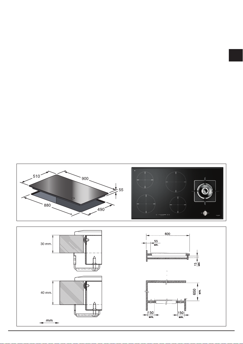
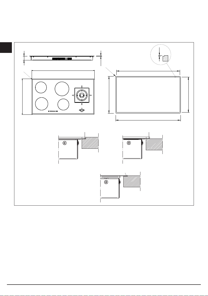
Posizionamento (Fig. 8-9)
L’apparecchio è previsto per essere incassato in un piano come illustrato nell’apposita
figura. Predisporre su tutto il perimetro del piano il sigillante a corredo. E’ sconsigliabile
l’installazione sopra un forno contrariamente accertarsi che:
- il forno sia munito di un efficace sistema di raffreddamento;
- che non avvenga in nessun caso passaggio di aria calda dal forno verso il piano;
- prevedere passaggi d’aria come indicato in figura.
Fig. 8
I
21
Fig. 9
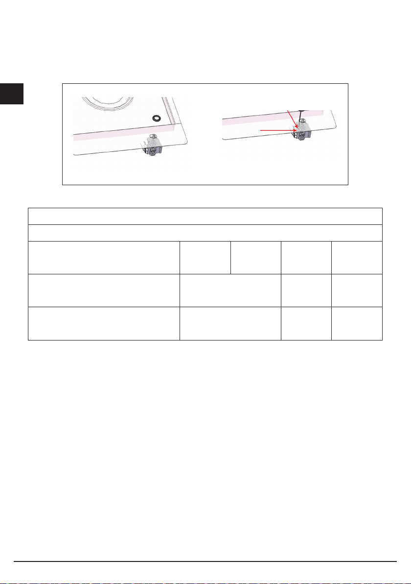
Page 22
I
POSIZIONE GUARNIZIONE SI GILLANTE
POSIZIONE GUARNIZIONE SIGI LLANTE
N.B. Per versione
56
4.8
R
1
0
900
Semifilotop l'abbassamento
di 4.8 mm non è necessario
R
3
.
5
880
0
+0.5
4.8
0
+1
510
NELLA VERSIONE FILOTO P
0
+1
511
NELLA VERSIONE SEMIFI LOTOP
POSIZIONE GUARNIZIONE SIGILLANTE
NELLA VERSIONE INOX PLANO FILOTOP
901
0
+1
490
0
+1
Fig. 10
22
Page 23
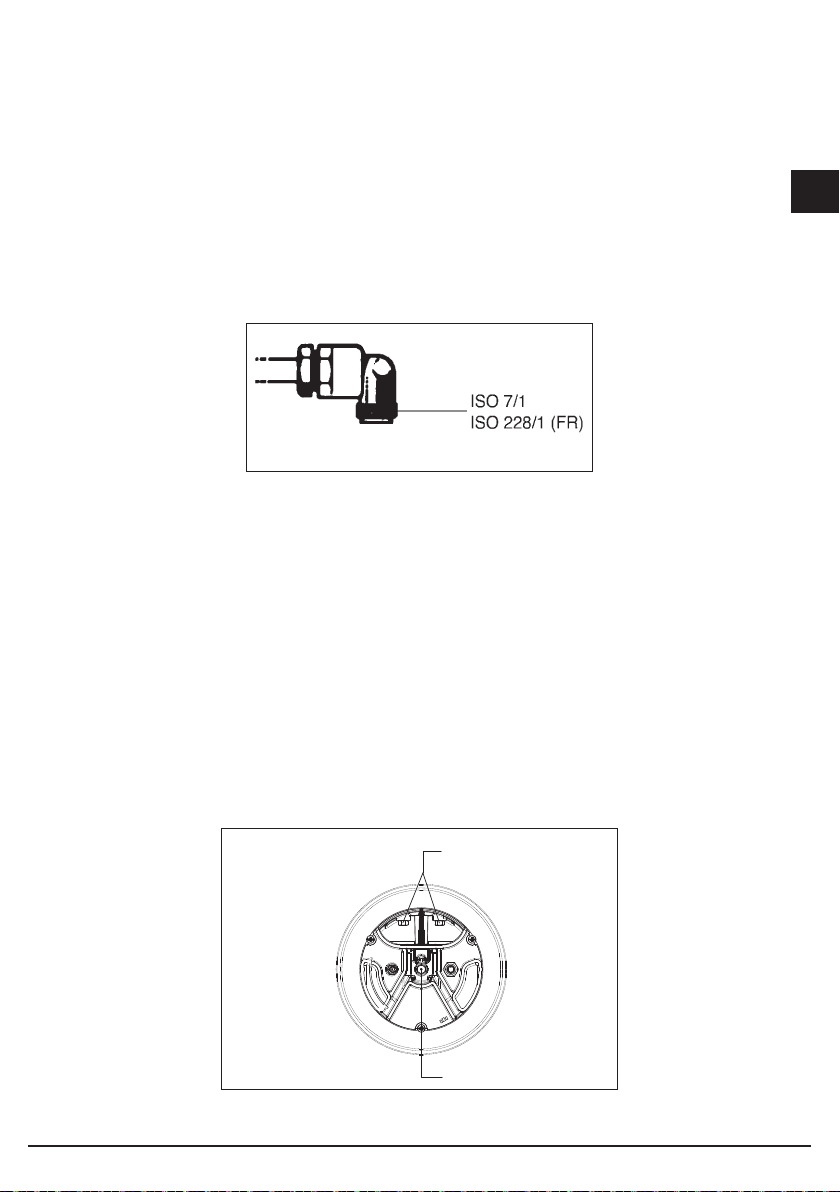
Collegamento gas (Fig. 11)
Collegare l’apparecchiatura alla bombola o all’impianto secondo le prescrizioni delle norme
in vigore accertandosi preventivamente che l’apparecchiatura sia predisposta al tipo di gas
disponibile. In caso contrario vedi: “Adattamento a diverso tipo di gas”. Verificare inoltre
che la pressione di alimentazione rientri nei valori riportati nella tabella: “Caratteristiche
utilizzatori”.
Fig. 11
Allacciamento metallico rigido/semirigido
Eseguire l’allacciamento con raccordi e tubi metallici (anche flessibili) in modo da non
provocare sollecitazioni agli organi interni all’apparecchio.
N.B. - Ad installazione ultimata controllare, con una soluzione saponosa, la perfetta tenuta
di tutto il sistema di collegamento.
Adattamento a diverso tipo di gas (Fig. 12)
Se l’apparecchiatura risulta predisposta per un diverso tipo di gas da quello di alimentazione
disponibile, si deve procedere:
• alla sostituzione dell’iniettore (Fig. 13) con i corrispondenti al tipo di gas da utilizzate (vedi
tabella “Caratteristiche utilizzatori”);
• per la regolazione del minimo agire con opportuno cacciavite sulla vite posta sul rubinetto
dopo averlo ruotato in posizione di minimo. Per GPL (butano/propano) avvitare a fondo.
I
23
B
A
Fig. 12
Page 24
I
Fig. 13
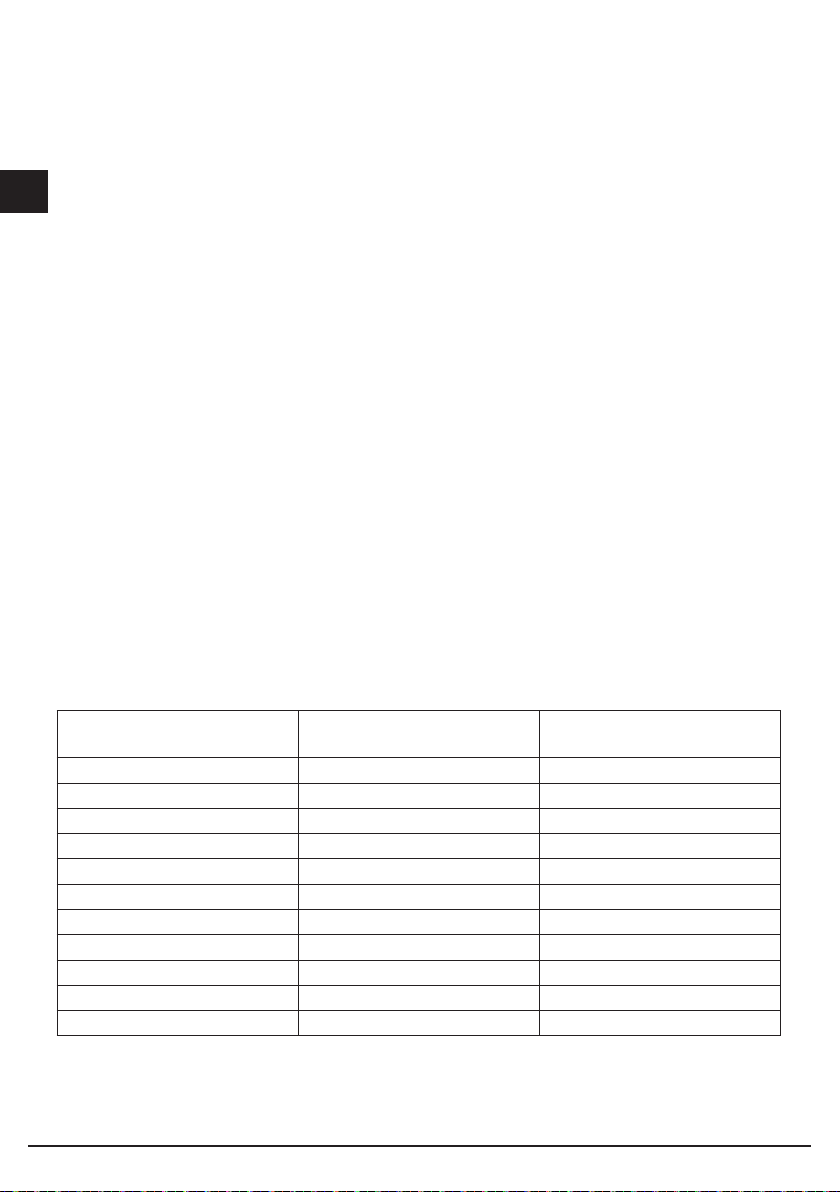
CARATTERISCHE URTILIZZATORI
BRUCIATORI GAS
ALIMENTAZIONE
TIPO PRESSIONE mbar
NORM.
Gas naturale G20 20 Wok Dual
Gas liquido G30/G31 28-30/37 Wok Dual
BRUCIATOREØINIETTORE
1/100
A - Ø71
B - Ø95
A - Ø46
B - Ø65
PORTATA
TERMICA
NOMINALE
4000 381
4000 291
CONSUMO
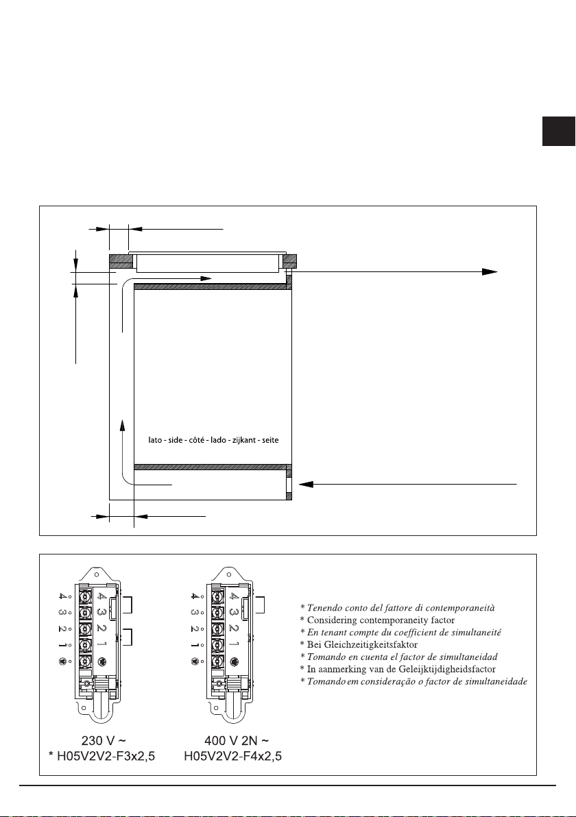
Collegamento elettrico
Prima di effettuare l’allacciamento elettrico accertarsi che:
- le caratteristiche dell’impianto siano tali da soddisfare quanto indicato sulla targa
matricola applicata sul fondo del piano;
- che l’impianto sia munito di un efficace collegamento di terra secondo le norme e le
disposizioni di legge in vigore. La messa a terra è obbligatoria a termini di legge.
Nel caso in cui l’apparecchiatura non sia munita di cavo e/o di relativa spina utilizzare
materiale idoneo per l’assorbimento indicato in targa matricola e per la temperatura di
lavoro. Il cavo in nessun punto dovrà raggiungere una temperatura superiore di 50°C a
quella ambiente.
Per il collegamento diretto alla rete è necessrio interporre un interruttore omnipolare
dimensionato per il carico di targa che assicuri la sconnesione della rete con una distanza
di apertura dei contatti che consenta la disconnesione completa nelle condizioni della
categoria di sovratensione III, conformemente alle regole di istallazione (il cavo di terra
giallo/verde non deve essere interrotto).
La presa o interrutore omnipolare devono essere facilmente raggiungibili con
l’apparecchiatura installata.
N.B.:
- Il costruttore declina ogni responsabilità nel caso che quanto sopra e le usuali norme
24
Page 25
antinfortunistiche non vengano rispettate.
Se il cavo di alimentazione è danneggiato, esso deve essere sostituito dal costruttore o dal
suo servizio assistenza tecnica o comunque da una persona con qualifica similare, in modo
da prevenire ogni rischio.
50 MIN.
I
20 MIN.
induzione - induction - induction - Induktion
- inducción - inductie - indução
ZONA FORNO O ARMADIETTO
OVEN ZONE OR CUPBOARD
ZONE FOUR OU PLACARD
OFENBEREICH ODER SCHRANK
ZONA HORNO O ARMARIO
OVENRUIMTE OF KASTJE
ZONA DO FORNO OU ARMÁRIO
50 MIN.
N
L
PE
aria - air - air - Luft - aire - lucht - ar
100 cm2 MIN.
(2 x 500)
aria - air - air - Luft - aire - lucht - ar
100 cm2 MIN.
Fig. 14
N
L2
L1
PE
25
Fig. 15
Page 26

Da 3.3 a 7.1 kw
I
Il piano esce di serie con il limitatore impostato a 3.3
kW.
Tramite le seguenti procedure è possibile passare da
un settaggio all’altro.
Entro i primi 2 minuti dall’ultimo collegamento alla
rete elettrica (nuova alimentazione) è possibile
entrare nel menù di configurazione. (se questo
passaggio lo si effettua dopo che il piano erà già stato
collegato alla rete elettrica bisogna aspettare qualche
secondo nel passaggio dal distacco al ricollegamento
dell’alimentazione).
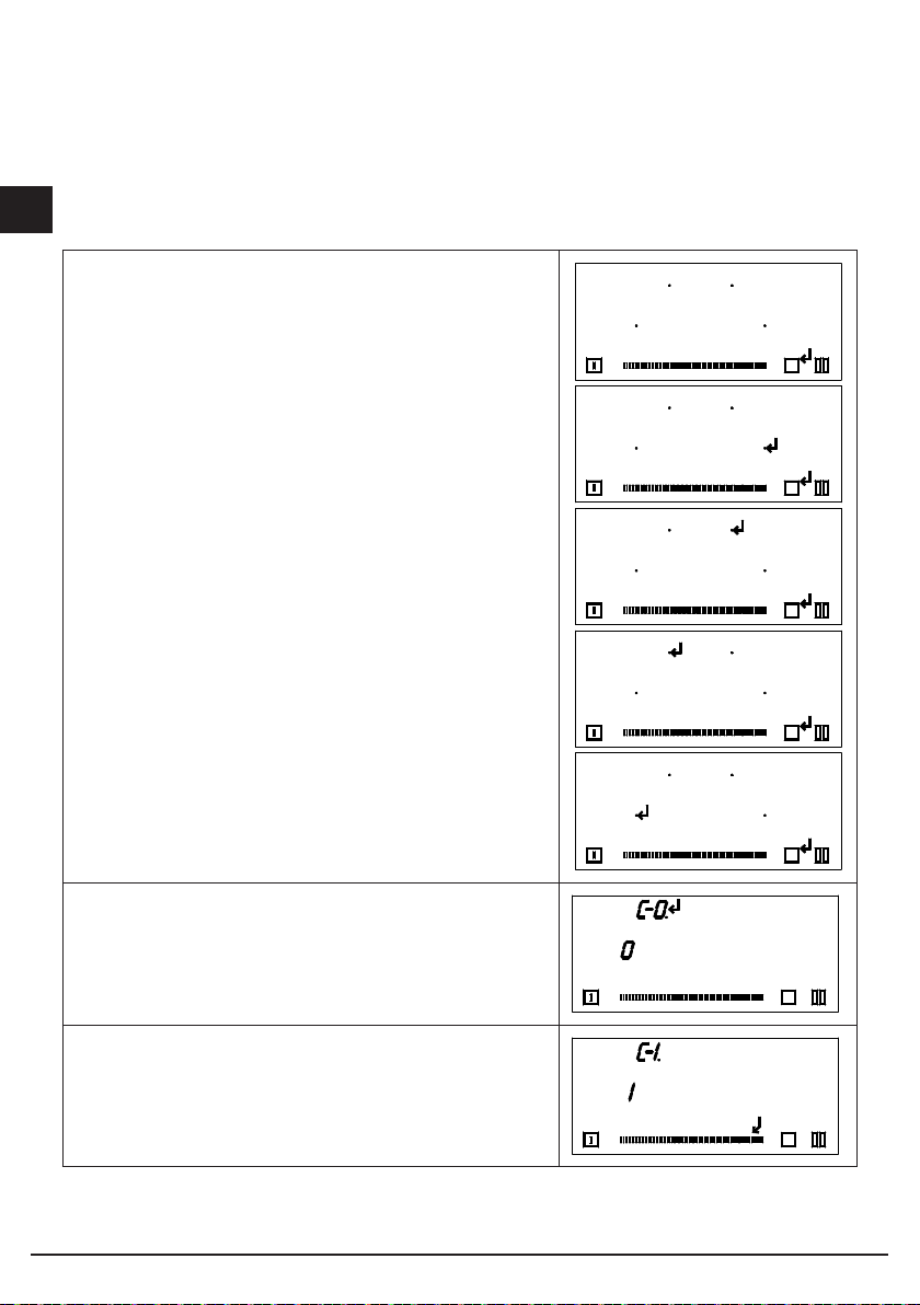
Premere il tasto P (Power Booster) e mantenere
premuto, a questo punto si accenderanno i 4 punti
decimali (.), mantenendo premuto il tasto P premere
a rotazione i 4 punti decimali partendo dal punto
anteriore destro.
Questa operazione deve essere fatta abbastanza
velocemente, un eventuale doppio bip indicherà la non
corretta sequenza o velocità di esecuzione.
P
P
P
P
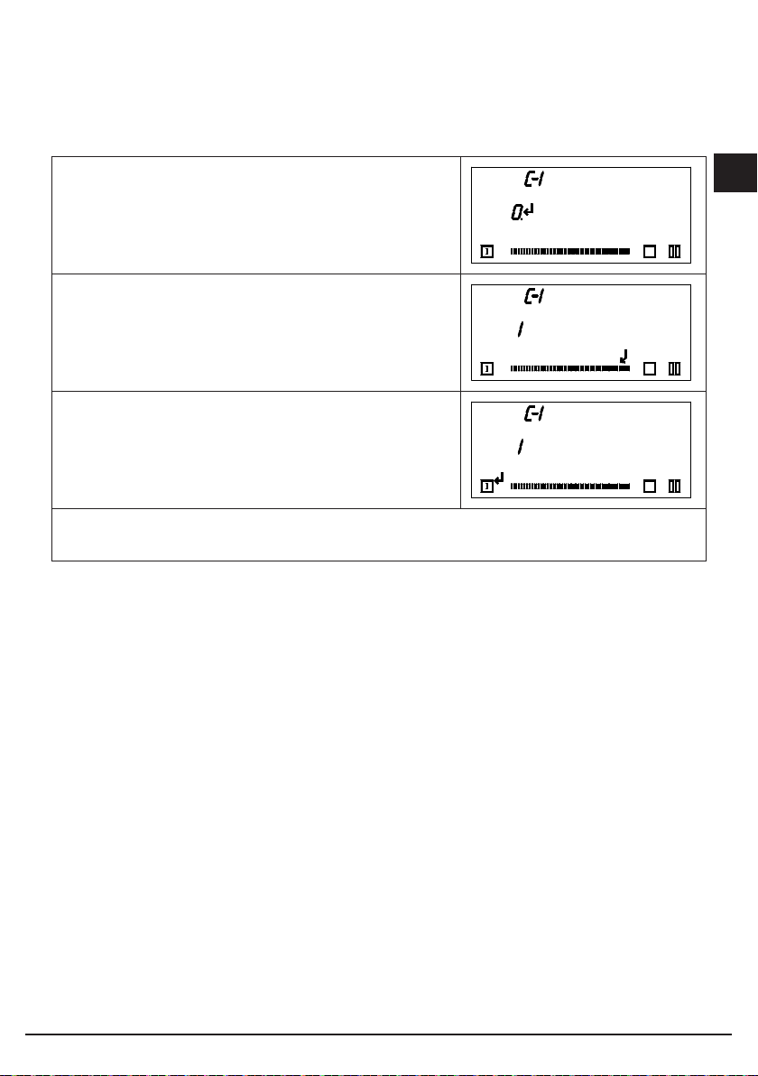
Nel primo display in alto lampeggerà C-0 ad
intermittenza, premerlo fino alla comparsa del punto
decimale.
Premere la zona del cursore evidenziata.
26
P
P
P
Page 27
Premere il display evidenziato.
P
Premere la zona del cursore evidenziata.
P
Premere li tasto accensione per 3 secondi per
salvare la configurazione.
P
N.B. L’installatore dovrà accertarsi che l’impianto elettrico nel quale verrà alloggiato il
piano cottura sia opportunamente dimensionato per il funzionamento a 7.1 kW
I
27
Page 28
Da 7.1 a 3.3 kW
I
Se si vuole riattivare il limitatore a 3.3 kW Tramite
le seguenti procedure è possibile passare da un
settaggio all’altro.
Entro i primi 2 minuti dall’ultimo collegamento alla
rete elettrica (nuova alimentazione) è possibile
entrare nel menù di configurazione. (se questo
passaggio lo si effettua dopo che il piano erà già stato
collegato alla rete elettrica bisogna aspettare qualche
secondo nel passaggio dal distacco al ricollegamento
dell’alimentazione)
Premere il tasto P (Power Booster) e mantenere
premuto, a questo punto si accenderanno i 4 punti
decimali (.), mantenendo premuto il tasto P premere
a rotazione i 4 punti decimali partendo dal punto
anteriore destro.
Questa operazione deve essere fatta abbastanza
velocemente, un eventuale doppio bip indicherà la non
corretta sequenza o velocità di esecuzione.
Nel primo display in alto lampeggerà C-0 ad
intermittenza, premerlo fino alla comparsa del punto
decimale.
P
P
P
P
P
P
Premere la zona del cursore evidenziata.
P
28
Page 29
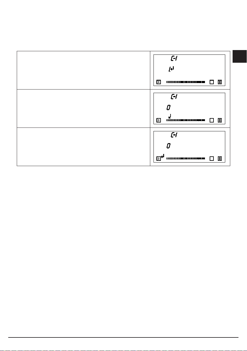
Premere il display evidenziato.
Premere la zona del cursore evidenziata.
Premere li tasto accensione per 3 secondi per salvare
la configurazione.
I
P
P
P
29
Page 30

Codice d’errore Descrizione Possibili cause Soluzione
C Se appare una “C” fissa
I
C/- Se appare una lettera
la zona cottura può
essere configurata.
“C” lampeggiante,
la zona cottura sarà
configurata. Una
volta configurata
correttamente la zona,
sul display appare il
segno “-”.
Se il segno “-” non
appare, verificare le
possibili cause di E/5.
Non è un errore: l’utente
è nel menu Service.
Non è un errore: l’utente
è nel menu Service.
2. sovratensione. Cambiare il modulo.
È possibile posizionare
una pentola appropriata
sulla relativa zona
cottura.
Attendere il segno “-”
oppure abbandonare
la configurazione
premendo il tasto di
selezione; la “C” non
lampeggia più.
E/7 Non assegnabile. Cambiare il modulo o
E/8 Difetto ventola. Difetto della ventola o
E/9 Problema del sensore T
E/A Problema dell’hardware
E/C Problema di
E/H Valore sensore fisso
No functionality
and no displaying
E Una “E” lampeggiante
sull’induttore.
del modulo di induzione.
configurazione.
(funzione test per
sensore T su induttore).
Sovratensione a livello di
alimentazione (nessuna
funzione).
su ogni zona cottura
indica che tutte le
configurazioni saranno
cancellate.
del controllo elettronico.
Segnale del sensore
al di fuori del range
di validità; difetto al
sensore o al sistema
elettronico.
Rilevato problema al
dispositivo hardware
dall’autotest del modulo.
2 zone cottura sono
dedicate allo stesso
elemento dell’IU.
Variazione temperatura
non sufficiente (10
°C) dopo 5 minuti
dall’accensione del
fornello.
Connessione 400V. Disconnettere
Non è un errore: l’utente
è nel menu Service.
l’interfaccia utente.
Cambiare il modulo.
Cambiare il modulo.
Cambiare il modulo.
1. Cancellare la
configurazione attuale
con menu Service.
Il sistema deve
raffreddarsi.
e riconnettere
l’alimentazione.
Configurazione
manuale.
30
Page 31

Codice d’errore Descrizione Possibili cause Soluzione
E/2
(Codice d’errore
diverso per alcune
IU)
E/3 Pentola non utilizzabile,
E/4 Modulo di induzione non
E/5 Nessuna comunicazione
E/6 Problema di
Superati i limiti di
temperatura
ad es. perdita di
caratteristiche
magnetiche a causa
della temperatura nella
parte inferiore.
configurato (tutti i moduli
di induzione rispondono
all’IU, ma ogni elemento
è collegato alla zona
cottura interessata).
tra l’IU e il modulo di
induzione.
alimentazione.
1. La temperatura della
pentola o del vetro è
troppo alta.
2. NTC (controllo
elettronica temperatura
troppo alta.
La pentola crea sul
modulo un livello
di funzionamento
inadeguato che può
danneggiare i dispositivi,
ad es. IGBT.
Il modulo di induzione
non è configurato.
Manca l’alimentazione al
modulo di induzione
Cablaggio errato o
difettoso.
1. Mancato rilevamento
della frequenza
dell’alimentazione
principale.
Il sistema deve
raffreddarsi.
1. L’errore si cancella
automaticamente dopo
8s e la zona cottura
può essere utilizzata
di nuovo. Se l’errore
si ripete è necessario
sostituire la pentola.
2. Se il codice di errore
appare senza che vi sia
una pentola sulla zona
cottura, il modulo deve
essere cambiato.
1. Cancellare la
configurazione
fornello e attivare la
configurazione manuale.
2. Avviare il menu
Servizio IU per
configurare il modulo di
induzione.
3. Se le soluzioni
indicate non risolvono
il problema, sostituire il
modulo.
Verificare
l’alimentazione e le
connessioni, sostituire il
modulo.
Verificare la tensione
e la frequenza
dell’alimentazione
principale
GB
SERVIZIO ASSISTENZA TECNICA: 199.151.195
31
Page 32

Page 33

Dear customer,
We thank you and congratulate you on your
choice.
This new carefully designed product,
manufactured with the highest quality
materials, has been carefully tested to satisfy
all your cooking demands.
We would therefore request you to read and
follow these easy instructions which will allow
you to obtain excellent results right from the
start.
May we wish you all the very best with your
modern appliance!
THE MANUFACTURER
I
GB
FR
DE
Italiano
English
Français
Deutsch
GB
Index
User instructions 34
Installation, 34
Use, 34
Maintenance Gas/Electrical, 35
Induction, 36
Operating principle, 37
Use, 38
Functions, 39
Maintenance, 50
Installation instructions 51
Installation, 51
Positioning, 51
Gas connection, 53
Adaptation to varius types of gas, 53
Electrical connection, 54
THIS APPLIANCE IS CONCEIVED FOR
DOMESTIC USE ONLY.
THE MANUFACTURER SHALL NOT IN
ANY WAY BE HELD RESPONSIBLE FOR
WHATEVER INJURIES OR DAMAGES
ARE CAUSED BY INCORRECT
INSTALLATION OR BY UNSUITABLE,
WRONG OR ABSURD USE.
THIS APPLIANCE IS NOT INTENDED
FOR USE BY PERSONS (INCLUDING
CHILDREN) WITH REDUCED PHYSICAL,
ES
Español
PT
Português
SENSORY OR MENTAL CAPABILITIES,
OR LACK OF EXPERIENCE AND
KNOWLEDGE, UNLESS THEY HAVE
BEEN GIVEN SUPERVISION OR
INSTRUCTION CONCERNING USE
OF THE APPLIANCE BY A PERSON
RESPONSIBLE FOR THEIR SAFETY.
CHILDREN SHOULD BE SUPERVISED
TO ENSURE THAT THEY DO NOT PLAY
WITH THE APPLIANCE.
33
Page 34

F1
F2
User instructions
Installation
All the operations concerned with the installation (electrical and gas connections, adaptation
to type of gas, necessary adjustments, etc.) must be carried out by qualified technicians,
in terms with the standards in force. For specific instructions, kindly read the part reserved
for the installation technician.
GB
DO NOT FOCUS INENSEL ON THE LEDS AND DISPLAYS.
Use
Use Gas burners
The ignition of the gas burner is carried out by putting a small flame to the upper part holes
of the burner, pressing and rotating the corresponding knob in an anti-clockwise manner,
until the maximum position has coincided with the marker. When the gas burner has been
turned on, adjust the flame according to need. The minimum position is found at the end of
the anti-clockwise rotation direction.
For models with automatic/ simultaneous (with one hand) ignition, it is sufficient to proceed
as described above using the corresponding knob. The electric spark between the ignition
plug and the burner provides the ignition of the burner itself. After ignition, immediately
release the push-button and adjust the flame according to need. For models with a
thermoelectric safety system, the burner is ignited as in the various cases described above,
keeping the knob fully pressed on the maximum position for approximately 3/5 seconds.
After releasing the knob, make sure the burner is actually lit.
N.B.
- We recommend the use of pots and pans with a diameter matching that of the burner,
thus preventing the flame from escaping from the bottom part and surrounding the pot;
- do not leave any empty pots or pans on the fire;
- do not use any tools for grill-cooking on Crystal hobs.
When cooking is finished, it is also a good norm to close the main gas pipe tap and/or
cylinder.
DWK models
Models SH 905 ID G DWK and SH 905 ID G DWK have a Dual Wok burner. The centre flame
(F1) can be lit by pressing the knob and turning it clockwise or the entire burner (F2) can
be lit as shown in the figure below.
F2
F1
F2
F1
34
Page 35

Important
GAS PROTEKT
On floors with thermoelectric protection (Gas Protekt) do not keep the ignite button pushed
for more than 15 seconds. If the burner has not ignited after 15 seconds, open the door of
the room and wait at least one minute before making a further attempt.
GAS
wok Ø 20-32
*with reduction grid
Fig. 1
Maintenance Gas/Electrical
Prior to any operation, disconnect the appliance from the electrical system. For long-life to
the equipment, a general cleaning operation must take place periodically, bearing in mind
the following:
• the glass, steel and/or enamelled parts must be cleaned with suitable non-abrasive or
corrosive products (found on the market). Avoid chlorine-base products (bleach, etc.);
• avoid leaving acid or alkaline substances on the working area (vinegar, salt, lemonjuice,
etc.);
• the wall baffle and the small covers (mobile parts of the burner) must be washed frequently
with boiling water and detergent, taking care to remove every possible encrustation. Dry
carefully and check that none of the burner holes is fully or partially clogged;
• the electrical parts are cleaned with a damp cloth and are lightly greased with lubricating
oil when still warm;
• the stainless steel grids of the working area, after having been heated, take on a bluish
tint which does not deteriorate the quality. To bring colour back to its original state, use
as lightly abrasive product.
N.B.- Cleaning of the taps must be carried out by qualified personnel, who must be
consulted in case of any functioning anomaly. Check periodically the state of conservation
of the flexible gas feed pipe. In case of leakage, call immediately the qualified technicians
for its replacement.
GB
DO NOT USE STEAM CLEANERS
35
Page 36

Induction
Heating by induction is the most efficient form of cooking available.
The heat is generated by an electromagnetic field, directly on the bottom of the pan or pot
used.
The surface which is free from contact remains virtually cold. When the cooking time is up
GB
and the container is removed, there is no residual heat. It is efficient become there is no
waste of energy due to dispersion, as happens with gas burners, it is 30 to 50% faster than
normal hobs using HGL technology and allows energy savings of up to 25%.
If liquid overflow from the container, it does not stick to the surface of the hob, because this
is just slightly warm.
LPC (Limited power system)
Induction is a useful technology and it becomes suitable for use in our homes thanks to
LPC. An intelligent system which succeeds in distributing the power of the various zones
to allow multiple or alternate use, always keeping the maximum power required below the
3 kW total consumption.
Caution: only the fitter may make alterations to the limited power system.
The manufacturer declines all responsibility.
36
Page 37

Operating principle
This is based on the electromagnetic properties of most cooking containers.
The electronic circuit governs the operation of the coil (inductor), creating a magnetic field.
The heat is transmitted by the container to the food.
Te cooking process takes place as follows:
- minimum dispersion (high performance);
- the removal of the pan (simply lifting it) automatically stops the system;
- the electronic system allows maximum flexibility and precision of regulation.
1 - Recipient
2 - Induced current
3 - Magnetic field
4 - Inductor
5 - Electronic circuit
6 - Electricity supply
Fig. 2
GB
37
Page 38

Use
First of all, position the pan in the chosen cooking area. The absence of the pan display
means the system cannot start.
GB
Pan detection
A certainty which distinguishes the knowledgeable use of technology in favour of the
consumer.
Installation
All operations relating to installation (electric connection) should be carried out by skilled
personnel in conformity with the rules in force.
For specific instructions see the part aimed at the installer.
Use
Touch sensitive keys
All operations can be performed using touch sensitive keys (capacitive sensors) located
on the front of the control board; each key has a corresponding display. All actions are
confirmed by an audible signal.
38
Page 39

1 ON/OFF
2 + Slider Area
3 - Slider Area
4 Power Booster (P)
5 Timer
6 Display Value Set
7A Display Timer
P
P
7B Display Timer
8 Pause indicator light
9 Timer indicator lights
10 Cooking area decimal point
11 Power indicator
12 LED Strip light
13 Pause
GB
Fig. 3
Functions
Switching the Touch Control ON/OFF
After switching on the power, the touch control takes about 1 second before it is ready to
use. After a reset all displays and LEDs glow for approx. 1 second. When this time is over all
displays and LEDs extinguish and the control is in the stand-by mode.
By operating the ON/OFF key the control can be turned into the ON-mode. The cooking zone
displays show a static “0”. If a cooking zone is in the “hot” status, the display shows a static
39
Page 40

“H” instead of “=”. The lower right corner of all cooking point displays flash at one-second
intervals to indicate that no cooking areas has been selected at the time.
After switching ON the electric control remains activated for 20 seconds. If no cooking
zone or timer selection follows within this period of time, the electronic control automatically
switches back into the stand-by mode.
GB
The control can only be switched ON if it identifies the ON/OFF key alone being operated.
Should it recognize key activation other than that, the control remains in the stand-by mode.
If the child safety feature is active when switching on, all cooking zones show “L” (LOCKED).
If the cooking zones are in a “hot” status, the display shows “L” and “H” in alternation.
When the Touch Control is ON it can be switched OFF at any time by operating the ON/OFF
key. This is also valid if the control has been locked (activated child safety feature).
The ON/OFF key has always priority in the switch-OFF function.
Automatic switch-OFF
When the control is ON it automatically switches OFF after 20 seconds if no cooking zone or
select key has been operated within this period of time. In the case of a cooking selection, the
automatic switch-OFF time is composed of 10 seconds deselection time for a cooking zone at
setting “0” and 10 seconds switch-OFF time.
Hob zone On/Off
With the Touch Control on, a hob zone can be selected by touching the dedicated display (6).
The corresponding display them shows the fixed spot on the display and “0” rather than “H” –
for very hot hob zones. The spots disappear on the display for all other hob zones.
At this point the cooking level can be selected by means of the Slider. In this way the
corresponding hob zone is activated. The maximum and minimum values are “9” (to the right)
and “0” (to the left).
Turning a single hob zone off
A single hob zone can be turned off by selecting a cooking level [0]. If a hot hob zone warning
light is on [H], this signal is alternately displayed with [0] and simultaneously with the spot on
the display.
Once the Touch Control is turned off, the display remains black or the symbol [H] is displayed
as a warning of a hot hob zone.
Switching OFF all cooking zones
Immediate switching OFF of all cooking zones can be achieved anytime by means of the ON/
OFF key. Once the Touch Control is switched off, the display remains off or the system [H] is
displayed as a warning that the cooking area is hot.
Switching OFF all cooking zones
Immediate switching OFF of all cooking zones can be achieved anytime by means of the
ON/OFF key. In the stand-by mode, an “H” appears on all cooking zones which are “hot”. All
other cooking zone displays are not illuminated.
40
Page 41

Wattage settings
The output of the cooking zones can be set in 9 steps which are indicated by figures “1” to
“9” by means of seven-segment LED displays.
touch control heat intensity
1 weak
2-3 gentle
4 slow
5-6 medium
7-8 strong
9 bright
A: INDUCTION COOKING ZONE ø160 LEVEL 9 = 1200W ABOUT, P = 1400 W
MINIMUM START THRESHOLD 700W
B: INDUCTION COOKING ZONE ø180 LEVEL 9 = 1400 W ABOUT, P = 2000 W
MINIMUM START THRESHOLD 1200W
C: INDUCTION COOKING ZONE ø200 LEVEL 9 = 2300 W ABOUT , P = 3000 W
MINIMUM START THRESHOLD 1200W
A ø160
B ø180
C ø200
A ø160
GB
THE ARRANGEMENT OF THE INDUCTORS, RECOGNIZABLE BASED ON THEIR
SIZES, ø160, ø180 AND ø200 CAN VARY BUT THEIR BEHAVIOUR MANAGED
BY THE LIMITER (3.3kW) REMAINS THE SAME
Fig. 4
41
Page 42

C ø200
A ø160
B ø180
9
0
0
P
0
8
P
0
8
0
8
9
A ø160
SEVERAL EXAMPLES OF MAXIMUM LEVELS ACCEPTED BY THE TOUCH
DISPLAY OF THE INDUCTION WITH LIMITER ON (3.3kW) WITH THE
INDUCTIVE ELEMENTS SHOWN.
GB
0
0
P
9
7
0
8
P
0
7
8
0
0
P
P
0
0
9
8
0
0
P
0
P
7
9
7
0
0
P
8
0
9
8
9
P
8
0
0
42
Page 43

9
0
0
P
0
0
9
P
C ø200
A ø160
B ø180
0
P
0
0
P
0
P
0
9
0
0
P
0
P
9
P
0
0
9
0
8
P
0
P
7
7
0
9
7
8
0
8
0
8
9
8
8
8
0
8
7
8
0
A ø160
P
0
8
9
1
1
8
0
1
1
7
0
8
8
9
8
Not possible with power limiter on
0
P
0
8
GB
All the cooking areas can function at the same time, even at the maximum level,
by disengaging the power limiter (operation at 7.1 kW). In this case, make sure the
electrical system where the surface is installed is properly dimensioned and that
the cable is of the type H05V2V2-FS 2.5 mm²
Note: Induction is produced with limiter engaged. The electronics will manage the
power up to the threshold limit of 3.3. To comply with this parameter, whether or not
you can turn on other cooking areas will depend on which inductor is on. A double
beep will warn you if you are trying to exceed this limit.
43
Fig. 5
Page 44

Automatic heat-up function
When the automatic heat-up function is activated the wattage of the cooking zone is at 100%
for a certain heat-up time which is dependent on the setting selected (continuous).
At the end of the heat-up time the electronic control switches back to the preselected
simmering setting.
GB
Starting process of the automatic heat-up
- The control is ON and a cooking zone will be selected
- When the power level 9 is reached the automatic heating is activated through a further
press of the slider in correspondence with the maximum value.
- The required power level is selected by means of the slider and the selected value is
shown on the display.
- At this point, you can select the level required for the continuation of the cooking using the
Slider area. The symbol “A” appears 3 seconds after the button is released, alternating
with the continuation level.
- The continuation level can be changed within 15 seconds from activation without disabling
the precooking boost. So, you must select the cooking area and then set the corresponding
cooking area.
- If the selection takes place after 15 seconds:
You can select a higher continuation level; this implies that the precooking time will
automatically be aligned to the currently selected continuation level.
Cooking level Precooking Boost A [min] Maximum operating time [h]
0 0 0
u 0 6
1 1 6
2 3 6
3 4,8 5
4 6,5 5
5 8,5 4
6 2,5 1,5
7 3,5 1,5
8 4,5 1,5
9 0,2 1,5
Residual heat indicator
It is meant to indicate to the user that the glass ceramic has a dangerous touch temperature
in the circumference of a cooking zone. The temperature will be determined following a
mathematical model and the remaining residual heat will be indicated by means of “H” on
the corresponding 7-segment display.
Heating up and cooling down will be calculated dependent on
• The selected setting (“0” to “9”)
44
Page 45

• The ON/OFF time of the relays
• After switching OFF the cooking zone the respective display shows “H” until the assigned
cooling zone temperature is mathematically in an uncritical level. (< 60°C).
Automatic switch-off (limited operating time)
Maximum operating time is defined for each hob zone. The maximum operating time
depends on the selected cooking level (see table). Once the maximum operating time has
expired, the hob zone is automatically deactivated.
Each activation of the hob zone status (modification of the cooking level etc.) resets the
countdown timer up to the initial start value.
The timer settings have priority in relation to the operating time limits, namely the hob zone
is turned off when the timer has expired and not when requested by the automatic power-off
(e.g.: timer of 99 minutes at cooking level 9).
Protection against unintended switching ON.
– If the electronic control detects continuous operation of a key for approx. 10 seconds,
it switches OFF automatically. The control sends out an audible failure signal for 10
seconds so that the user can remove the object which has been mistakenly placed onto
the operation surface. The displays show the failure code “ER03”.
– If the failure carries on for more than 10 seconds, only the code “ER03” will be displayed
as long as the failure is detected by the electronic control. If the cooking zone is in the
“hot” status, “H” will appear on the display in alternation with the failure signal.
– If no cooking zone is activated within 20 seconds after switching ON by means of the
Power-key, the control switches back from the ON condition to stand-by mode.
– When the control is switched ON, the ON/OFF Key has priority over all other keys so that
the control can be switched OFF anytime, even in case of multiple or continuous operation
of keys.
– In the stand-by mode a continuous operation will not be signalled. However, before the
electronic control can be switched ON again, it has to recognize that all keys are not
operated.
GB
Child safety lock (childproof function)
The child safety lock can only be activated with the Touch Control on if no hob zones are
active and no timer has been selected.
It is therefore necessary to simultaneously press the hob zone display of the front right hob
zone (FR) and the special Power Booster (P), then press the display of the hob area (FR)
again. At this point all displays show the symbol [L] denoting LOCKED (=child lock against
accidental activation). Any hot hob zones warning lights [H] are shown alternately to the
symbol [L].
This procedure must be completed within 10 seconds and no other key must be pressed
except for that mentioned, otherwise the procedure is cancelled because incomplete.
The electronics remain in the locked condition until the key is released, even if in the meantime
the control unit was turned off and turned back on again. Reinstatement (disconnecting from
the mains) of the command does not remove the lock.
45
Page 46

Unlocking for cooking
The front right hob zone display (FR) and the special Power Booster (P) must be
simultaneously pressed to unlock and prepare the Touch Control unit.
The symbol [L] indicating LOCKED disappears from the display. The displays of all the hob
zones display [0], together with a flashing dot. Possible hot hob zone [H] warning lights
GB
are permanently displayed. After the command unit is turned off, the child safety lock will
reactivate again.
This procedure must be completed within 10 seconds and no other key must be pressed
except for that mentioned, otherwise the procedure is cancelled. Other keys cannot be
activated. The power button only can be used (Power) to turn off the Touch Control (and
restart the procedure).
Permanent unlock
The hob zone display of the front right hob zone (FR) and the special Power Booster (P)
must be simultaneously pressed, then press the special Power Booster again.
This procedure must be completed within 10 seconds and no other key must be pressed
except for that mentioned. The Touch Control remains in the Off mode (all displays are
blank), failing which the procedure is cancelled and the Touch Control switches to Off mode
after 20 seconds.
If the control unit is activated by pressing the ON/OFF key, all displays will show the “0”
symbol, the dots on the display continue to flash and the command unit can be used for
cooking. In the presence of the hot hob zone warning lights [H], this message is displayed
alternately with [0] and at the same time with the dot on the display.
Acoustic signalling (buzzer)
The following activities carried out during the operation of the Touch Control are signalled
by a buzzer:
– Single brief acoustic signal for the regular activation of a key. The acoustic signal is only
emitted on the first activation for the Slider area. No acoustic signal is emitted during the
modification of the values.
– A longer intermittent acoustic signal for the permanent use of the keys for a more prolonged
period (> 10 seconds
– Timer time-out
Timer function (CL)
There are two different types of timer function available:
– Independent Timer 1.99 minutes: acoustic signal with timing. This function can be activated
only if there are no other hob zones functioning (all levels = 0). If any of the hob zones
are activated (level >0) the independent timer remains active. If the timer must be used
to switch off a cooking area (see timer for cooking area), then the command must first be
turned off and on.
– Hob zone timer 1.99 minutes: This function can be activated as long as a hob is on (level
< 0; dot on the display). Four cooking areas to be deactivated are freely programmable
timer and beep.
46
Page 47

Setting a timer value
– Adjustment by means of the slider area.
– The adjustment of the first digit usually occurs first, followed by the adjustment of the
second digit.
– Within 10 seconds after setting the second digit, the value might reset (the dot on the timer
display and when there is a specific timer for a hob zone the assigned LED flashing).
– For the display of the active timer, the timer value can be set to [0] by directly pressing [0]
on the slider (left side).
Deactivation of an active timer
– A timer can be deactivated by setting the value to 0.
– An independent timer can be deactivated through the double activation of the power key
(1st TC active, 2nd TC and Timers off).
Independent timer
– If the control unit is activated (the displays of all hob zones show [0]), the independent
timer can be activated by pressing the timer selection key. The display shows 0- and is
ready for setting the first digit of the timer. By pressing the timer display, you can go on
to programming the second digit of the timer. The timer is disconnected after 10 seconds
(blank display) if no other settings are made. If a timer value is set without the activation of
a hob zone within 10 seconds, the displays of the hob zones are also disconnected). The
hot hob zones warning lights [H] are permanently displayed.
– Until the timer is selected (the dot on the display flashes for 10 seconds), it can be set. The
setting range is 0-99 minutes in individual steps, for the Slider area.
– The countdown starts immediately after the timer value has been set, starting from the
last set value.
– The timer is automatically deselected after 10 seconds and the time display indicates the
timer value. Once the set time has expired, an acoustic signal is activated and the time
display shows the flashing symbol “00”.
– The beep stops after 2 minutes and/or by pressing any button. Subsequently, the timer
display will stop blinking and switch off. Any hot cooking area warning lights [H] are
displayed permanently.
– By pressing the POWER key, the control unit can be switched at any time from the “sole
timer function” to a hob zone, with or without an active independent timer.If you switch
the Touch Control back to active mode with an independently active timer, first select the
independent timer highlighted by the active selection “-”; in this way you can reset it or
change its value. If you select a cooking area, the “-” on the display disappears and the
time set on the independent timer is displayed. If there is an independent timer set, you
cannot program a specific timer for a cooking area. Once a hob zone has been selected,
the decimal point on the timer display disappears and a decimal point on the hob zone
display flashes. When the control unit is turned off by means of the POWER key, the
independent timer (if functioning still) is also turned off.
GB
47
Page 48

Programming of the specific hob zone timer
The power-on of the Touch Control enables the timer setting for dedicated hob zones.
– If you activate a cooking area (cooking area level > 0) and then select the timer display
(within 10 seconds), you can assign a value of the timer to the cooking area as a function
of switching off the cooking area. The LED corresponding to the timer indicates the hob
GB
zone for which the timer has been activated.
– As soon as the timer is selected, one of the LEDs (9) corresponding to the cooking
area flashes and the timer shows “0-” indicating that the first digit of the timer can be
programmed using the slider area. Once you have set the first digit, pressing the timer
display allows you to set the second digit.
– When switching from one hob zone to another, the timer display shows the current timer
value of the related hob zone. The timer setting of the other hob zones remain active.
– The other settings are the same as those for the independent timer.
– If more than one timer is active, the display shows the value of the lowest timer (after a
deselection time of 10 seconds).
– After the set time has expired, an acoustic signal is activated and the timer display shows
the flashing “00” symbol. The LED of the corresponding timer flashes at the same time.
The cooking area programmed turns off and the symbol “0” is displayed fixed. The symbol
“H” is displayed after 10 seconds (deselection time) in correspondence with a hot hob
zone (“hot”). Otherwise the symbol “0” is displayed.
– The acoustic signal and flashing hob zone LED stop after 2 minutes and/or activating any
key.
At this point the displays disappear and the hob zone remains deselected.
The behaviour of the specific hob zone timer is similar to that of the independent timer.
If a timer is programmed for a hob zone, the limitation of the operating time depend on the
timer value and not on the value of the standard table.
The precision of the timer value depends on the precision of the clock μC that can deviate
by +/- 4% in 99 minutes.
Food warmer function (optional)
The food warmer function keeps the food on a hob zone warm.
In this case the selected hob zone is activated at low power.
When the food warmer function is activated for a hob zone, the corresponding display
indicates the “u” symbol (see symbols).
Activation/Deactivation
The food warming function can also be activated as an additional cooking level between 0
and 1.
To use the foodwarmer function, select an area, set it to 1 using the slider and then
immediately to 0. For the operating times, see the table.
Time limitation of the heat holding function
For microbiological reasons, the food warming function should not be used for excessively
prolonged periods (maximum 1 hour. For this reason the Touch Control automatically
48
Page 49

switches off after 2 hours).
PAUSE
Activation of the pause function
When at least one hob zone is functioning, the heating elements can be deactivated by
pressing the Pause key.
The pause display has priority.
The timers that have already been programmed (also for the independent timer) are stopped
and do not function during the pause time. The automatic heater and booster are also
deactivated on all the hob zones during the activation, while the calculation of the residual
heat and the limitation of the operating time continues to function without being stopped.
The LEDs of the other functions (timer) remain on depending on their status.
The pause can last up to 10 minutes. If it is not terminated within this time interval, the
command is deactivated. The hob zone can be switched at any time by means of the On/Off
key. Any active pause functions are in this way terminated.
Termination of the Pause function
To terminate the Pause mode and start the operation again, the Pause key and any other
key (not the same key again) must be activated within 10 seconds.
In this way the function existing before the Pause is re-established. If no other key is activated
within the 10 seconds, the hob zone is also switched off.
Additional functions of the pause LED
The indicator light behaves in the following way:
When the Pause function is deactivated, the LED remains off. When the pause function is
activated, the LED remains on. The LED flashes during the waiting time before a second key
is pressed. The LED also flashes if the supplementary recall function is possible after restart.
Recall (optional for the multifunction key)
The settings can be quickly recovered after power-off by means of the power key, the
operator has 6 seconds to activate the Pause key. This function can only be performed if it
was previously active and
was confirmed by an acoustic signal of the key.
The following operations are restored:
– cooking level of all hob zones
– minutes and seconds of the programmed hob zone timers
– switching conditions of the external circuits (guaranteed by the reminder function of the
external circuit)
– heat-up function
The following operations are not restored:
– limitation of the timer time (the operator deactivated it)
– timer operating cycle (a new cycle is started after restart)
– If the delay time of a power reduction is running when switching off (power management),
but the new cooking level has not yet been detected, the recall may not restore the last
setting of the operator (to be executed as a priority). This particular case can only occur
GB
49
Page 50

during the 3 seconds delay time of reduced power.
Note: If there is even a slight crack in the cooking surface, immediately disconnect
the power.
GB
Maintenance
First of all remove stray food bits and grease drops from the cooking surface with the special
scraper. Then clean in the cooking area with specific products for vitroceramic cooking
surfaces and a paper towel and then rinse with water and dry with a clean cloth.
Pieces of aluminium foil and plastic material which have inadvertently melted or sugar
remains or food with a high saccharine content have to be removed with the special scraper.
This is to avoid any possible damage to the surface of the top. Under no circumstances
should abrasive cones or irritating chemical detergents, such as oven sprays or stain
removers, be used.
DO NOT USE STEAM CLEANERS
NO NO YES
Fig. 6
Fig. 7
50
Page 51

Installation instructions
Installation
These instructions are aimed at qualified fitters as a guide to installation, adjustment and
maintenance in compliance with the laws and standards in force. The operations must
always be carried out with the appliance disconnected from the electricity supply.
This appliance is not provided with a combustion product discharge. It is recommended
that it be installed insufficiently aerated places, in terms of the laws in force. The quantity of
air which is necessary for combustion must not be below 2.0 m
power. See table of burner power.
Positioning (Fig. 8-9)
The appliance is made to be fitted into a counter top, as show in the figure. Apply the
sealant supplied around the whole perimeter of the hob. Installation over an oven is not
recommended, but if this is necessary, check that:
- the oven has an efficient cooling system;
- there is no passage of hot air from the oven to the hob;
- allow air passages as shown in the figure.
3
/h for each kW of installed
GB
Fig. 8
Fig. 9
51
Page 52

GB
POSIZIONE GUARNIZIONE SI GILLANTE
POSIZIONE GUARNIZIONE SIGI LLANTE
0
+0.5
N.B. For the Semi-flush top
N.B. Per versione
version, it is not necessary to
56
4.8
R
1
0
900
Semifilotop l'abbassamento
lower the hob by 4.8 mm
di 4.8 mm non è necessario
R
3
.
5
880
4.8
0
+1
510
POSITION OF SEALANT IN THE
FILOTOP VERSION
NELLA VERSIONE FILOTO P
0
+1
511
POSITION OF SEALANT IN THE
SEMIFILOTOP VERSION
NELLA VERSIONE SEMIFI LOTOP
POSITION OF SEALANT IN THE INOX
POSIZIONE GUARNIZIONE SIGILLANTE
NELLA VERSIONE INOX PLANO FILOTOP
PLANO FILOTOP VERSION
901
0
+1
490
0
+1
Fig. 10
52
Page 53

Gas connection (Fig. 10)
Connect the appliance to the gas cylinder or to the installation according to the prescribed
standards in force, and ensure beforehand, that the appliance matches the type of gas
available. Other wise, see ”Adaptation to various types of gas”. Further more, check that the
feed pressure fall swithin the values described on the table: ”User chacteristics”.
Fig. 11
Rigid/semi rigid metalconnection
Carry out the connection with fittings and metal pipes (even flexible pipes) so as to obtain
counter stress the inner parts of the appliance.
N.B. - when the installation has been carried out, check the perfect sealing of the entire
connection system, by using a soapy solution.
Adaptation to varius types of gas (Fig. 11)
Should the appliance be pre-set for a different type of gas than available, procreed as
follows:
• replace the injector (Fig. 13) with the corresponding type of gas to be used (see table
“User characteristics“);
• to adjust to the minimum, use a screwdriver on the screw placed on the tap (Fig. 13) after
turning the tap to its minimum position. For GPL (butane/propane) screw tight.
GB
53
B
A
Fig. 12
Page 54

GB
Fig. 13
USER CHARACTERISTICS
GAS BURNERS
FEED
TYPE PRESSURE mbar
NORM.
Natural gas G20 20 Wok Dual
Liquefied
gas
G30/G31 28-30/37 Wok Dual
BURNER
Ø INJECTORS
1/100
A - Ø71
B - Ø95
A - Ø46
B - Ø65
THERMAL
CAPACITY
4000 381
4000 291
CONSUMPTION
Electrical connection
Before connecting to the electricity supply, ensure that:
- the characteristics of the system are such as to satisfy that indicated on the registration plate applied to
the bottom of the hob;
- the system has an effective earth connection compliant with the standards and laws in force. Connection
to earth is compulsory by law.
If the appliance has no cable and/or plug, use material suitable for the absorption indicated on the
registration plate and for the working temperature. The cable must not reach a temperature higher than
50°C above room temperature in any point.
For direct connection to the network it is necessary to fit an omnipolar switch of a suitable size to ensure
disconnection of he network with a contact opening distance that allows complete disconnection in the
conditions of the overtension category III, compliant with the installation regulations (the yellow/green
earth wire must not be interrupted).
The omnipolar socket or switch must be easy to reach when the appliance is installed.
N.B.:
- The manufacturer declines all responsibility if the usual accident prevention standards and the above
instructions are not observed.
If the power cable is damaged, it must be replaced by the manufacturer or by the manufacturer’s technical
servicing network, or by a similarly qualified operator, to prevent every possible risk.
54
Page 55

50 MIN.
20 MIN.
induzione - induction - induction - Induktion
- inducción - inductie - indução
ZONA FORNO O ARMADIETTO
OVEN ZONE OR CUPBOARD
ZONE FOUR OU PLACARD
OFENBEREICH ODER SCHRANK
ZONA HORNO O ARMARIO
OVENRUIMTE OF KASTJE
ZONA DO FORNO OU ARMÁRIO
50 MIN.
N
L
PE
L2
L1
PE
aria - air - air - Luft - aire - lucht - ar
100 cm2 MIN.
(2 x 500)
aria - air - air - Luft - aire - lucht - ar
GB
100 cm2 MIN.
Fig. 14
N
55
Fig. 15
Page 56

From 3.3 to 7.1 kW
GB
The surface comes standard with the limiter set to 3.3
kW. It is possible to change from one setting to another
with the following procedures.
Within the first 2 minutes after the last connection
to the mains (new power supply), you can enter the
configuration menu. (if this transition is made after the
surface was already connected to the mains you have
to wait a few seconds in the step of disconnecting and
reconnecting the power supply).
Press and hold the P (Power Booster) key.
At this point the 4 decimal points (.) turn on.
Hold down the P key and press the 4 decimal points in
rotation, starting from the front right.
This operation must be done rather quickly and a
double beep will warn you if the sequence or speed of
execution is not correct.
In the first display above, C-0 will flash intermittently.
Press it until the decimal point appears.
P
P
P
P
P
P
Press the highlighted area of the cursor.
P
56
Page 57

Press the highlighted display.
P
Press the highlighted area of the cursor.
P
Press the ON/OFF button for 3 seconds to save the
configuration.
P
Note: The installer must make sure that the electrical system in which the cooking surface
will be installed is suitably dimensioned for operation at 7.1 kW
GB
57
Page 58

From 7.1 to 3.3 kW
GB
If you want to restore the limiter to 3.3 kW It is possible
to change from one setting to another with the following
procedures.
Within the first 2 minutes after the last connection
to the mains (new power supply), you can enter the
configuration menu. (if this transition is made after the
surface was already connected to the mains you have
to wait a few seconds in the step of disconnecting and
reconnecting the power supply).
Press and hold the P (Power Booster) key.
At this point the 4 decimal points (.) turn on.
Hold down the P key and press the 4 decimal points in
rotation, starting from the front right.
This operation must be done rather quickly and a
double beep will warn you if the sequence or speed of
execution is not correct.
In the first display above, C-0 will flash intermittently.
Press it until the decimal point appears.
P
P
P
P
P
P
Press the highlighted area of the cursor.
P
58
Page 59

Press the highlighted display.
Press the highlighted area of the cursor.
Press the ON/OFF button for 3 seconds to save the
configuration.
P
P
P
GB
59
Page 60

Error code description Possible causes Error recovery
C The cooking zone can
be configured if a static
“C” is shown.
It’s not an error, the user
is in the serivice menu.
A suitably pan must be
placed on the relevant
cooking zone.
C/- The cooking zone will be
GB
E/7 Non assignable faillure. Exchange modul or User
E/8 Fan faillure. Fan or control electronic
E/9 Defect T sensor on
E/A Hardware defect of
E/C Configuration failure. 2 cooking zone are
E/H Fixed sensor value (test
No functionality
and no displaying
configured if a blinking
“C” is shown. After a
successful configuration
the relevant display
shows “-”.
When the “-” is not
displayed please check
the possible causes of
the E/5.
inductor.
induction modul.
function for T sensor on
inductor).
Overvoltage on the
switch mode power
supply (jno fuctionality).
The user is in the
service menue, it’s not
an error.
2. over voltage. Exchange the module.
is defect.
Sensor signal out of
valid range; sensor or
electronic is defect.
Defect hardware device
detected by the self
check of the modul.
dedicated to the same
element of the UI.
Not enough temperature
change (10K) within 5
min after switch on the
hob.
400V connection. Disconnet and
Wait for the sysmbol
“-” or abort the
configuratuib activities
by pressing the
selectkey and the “C”
does not blink anymore.
Interface.
Exchange the modul.
Exchange the modul.
Exchange the modul.
1. Erase the actual
configuration manual
with service menù.
Systerm must cool
down.
correct the power line
connection.
E A blinking “E” on each
E/2
(Error code
different for some
UI)
cooking zone indicates,
that all configs will be.
Temperature limits are
excessed.
The user is in the
service menù, it’s not an
error.
1. Pot or glas
temperature is to
2. NTC - electronik
temperature to high.
60
Manual configuration.
System must cool down.
Page 61

Error code description Possible causes Error recovery
E/3 Unsustable pot, e.g.
lost of the magnetic
characteristics because
of temperature in the
bottom.
E/4 Unconfigured induction
modul (all induction
modul answer to UI, but
any element is related
to the effected cooking
zone).
E/5 No communication
between UI and
inducation modul.
E/6 Main power disturbace . 1. Failure in main power
Pot creates on the
modul an improper
operating point which
can destroy devices,
e.g. IGBT.
Induction modul is not
configured.
No power supply of
induction modul
Mal cabeling or defect
of.
frequency detection.
1. the error is
automaticly cancelled
after 8s and the cooking
zone can be used
again. In case of further
upcoming errors the post
have to be changed.
2. the modul has to be
changed if the error
comes without an pot on
the cooking zone.
1. Delet the hob
configuration and
activate the manual
configuration.
2. Start the UI service
menue to configure the
imduction modul.
3. If the listed points are
not succesful replace
the modul.
Check power and lin
connections is the
connention ok, replace
the modul.
Check main power
voltage and frequency,
if ok.
GB
61
Page 62

Page 63

Chère cliente,
merci et sincères félicitations pour le choix
que vous avez fait.
Ce nouveau produit, développé avec soin et
fabriqué avec des matières de toute première
qualité, a été soigneusement rodé pour
satisfaire toutes Vos exigences d’une cuisson
parfaite.
Veuillez lire attentivement les instructions
simples portées sur cette notice qui vous
permettront d’obtenir d’excellents résultats
dès la première utilisation. Nous vous
souhaitons une entière et pleine satisfaction
quant à l’utilisation de cet appareil moderne.
I
GB
FR
DE
Italiano
English
Français
Deutsch
FR
Index
E CONSTRUCTEUR
Notice d’emploi 64
Installation, 64
Mode d’emploi, 64
Entretien Gaz/Électric, 65
Induction, 66
Principe de fonctionnement, 67
Utilisation, 68
Functions, 69
Entretien, 80
Instructions pour l’installateur 82
Installation, 82
Positionnement, 82
Connexion gaz, 84
Adaptation à un différent type de gaz, 84
Branchement électrique, 85
CE PRODUIT A ETE CONÇU POUR UN
USAGE DOMESTIQUE.
LE CONSTRUCTEUR DECLINE
TOUTE RESPONSABILITÉ EN CAS DE
DOMMAGES SUBIS PAR LES CHOSES
OU LES PERSONNES DERIVANT D’UNE
INSTALLATION INCORRECTE OU
D’UN USAGE IMPROPRE, ERRONE OU
INCOHERENT.
NE PAS CONFIER L’UTILISATION DE
L’APPAREIL A DES PERSONNES (Y
ES
Español
PT
Português
COMPRIS DES ENFANTS) AYANT
DES CAPACITES PHYSIQUES,
SENSORIELLES OU MENTALES
REDUITES, OU A DES PERSONNES QUI
NE POSSEDENT PAS L’EXPERIENCE ET
LES CONNAISSANCES NECESSAIRES
; LA SUPERVISION D’UN ADULTE
RESPONSABLE POUR LEUR SECURITE
ET EN MESURE DE COMPRENDRE LE
MODE D’EMPLOI DE L’APPAREIL EST
OBLIGATOIRE.
IL FAUT SURVEILLER LES ENFANTS
POUR S’ASSURER QU’ILS NE JOUENT
PAS AVEC L’APPAREIL.
63
Page 64

F1
F2
Notice d’emploi
Installation
Toutes les opérations relatives à l’installation (branchement électrique, raccordement gaz,
adaptation au type de gaz, réglages nécessaires, etc...) doivent être effectuées par des
spécialistes suivant les normes en vigueur. Pour les instructions spécifiques, voir la partie
qui concerne les modalités d’installation.
NE PAS FIXER INTENSEMENT LES VOYANTS ET L’AFFICHEUR DU REGARD.
FR
Mode d’emploi
Brûleurs à gaz
On allume le brûleur en approchant une petite flamme aux trous de sa partie supérieure
en poussant et tournant dans le sens contraire des aiguilles d’une montre la manette
correspondant jusqu’à faire coïncider l’aiguille avec la position de maximum. Quand le
bruleur est en marche, règler la flamme selon la nécéssité. La position de minimum se
trouve à la fin de la rotation contraire au sens des aiguilles d’une montre.
Pour les modèles à allumage automatique/simultané (à une main), il suffit d’agir sur le
bouton correspondant, comme il est indiqué ci-dessus. La décharge électrique entre la
petite bougie et le brûleur allume le brûleur interessé.
Quand le brûleur est allumé, lâcher la manette, et regler la flamme selon nécéssité. Dans
le cas de modèles doués de sûreté thermoélectrique, l’allumage du brûleur a lieu comme
dans les cas décrits ci-dessus en appuyant à fond sur la manette placée à la position
maximale pendant environ 3/5 secondes. Au moment où vous relâchez la manette, assurezvous que le brûleur est allumé.
N.B.:
- On Vous conseille d’utiliser des casseroles avec un diamètre proportionné aux brûleurs
évitant que la flamme au maximum déborde de leur fond;
- ne laissez jamais de casseroles vides sur le feu allumé;
- n’employez pas d’ustensiles pour cuisson grill sur les plaques dessus verre.
A la fin de la cuisson il faut fermer le robinet principal du conduit et/ou de la bouteille.
Modèles DWK
Les modèles SH 905 ID G DWK et SH 905 ID G DWK sont équipés d’un brûleur Dual Wok.
Il est possible d’allumer la flamme centrale (F1) en tournant et en pressant la bouton dans
le sens horaire, ou allumer tout le brûleur (F1) de la façon indiquée sur la figure ci-dessous.
F2
F1
F2
F1
64
Page 65

important
GAS PROTEKT
Sur les plaques dotées de sécurité thermoélectrique (Gas Protekt), ne pas activer l’allumage
pendant plus de 15 secondes.
Si , après 15 secondes le brûleur ne s’est pas allumé, ouvrir la porte de la pièce et attendre
au moins une minute avant de réessayer.
GAS
wok Ø 20-32
*avec grille de réduction
Fig. 1
Entretien Gaz/Électric
Avant de toute opèration, débrancher l’appareil du reseau électrique. Pour assurer une
longue vie á l’appareil il faut absolument effectuer de temps en temps un nettoyage général
soigneux en gardant à l’esprit ce qui suit:
• les parties en vitre, acier et/ou émaillées doivent etre nettoyées avec des produits
appropriés (faciles à trouver ans les magasins) non abrasifs ni corrosifs. Eviter les
produits qui contiennent du chlore (eau de Javel.etc,);
• éviter de laisser sur la table de travail des substances acides ou alcalines (vinaigre, sel,
jus de citron, etc.);
• les orifices du bruleûr et les chapeaux (pièces mobiles du bruleur) doivent etre
frequemment lavés avec de l’eau bouillante et du détergent, en ayant soin d’enlever tout
incrustation, ensuite ils doivent etre essuyés soigneusement, en controlant que tous les
trous soient débouchés;
• les plaques électriques doivent être nettoyées avec un torchon humide et un peu huilées
quand elles sont encore tièdes;
• les grilles inox du plan de travail après avoir été chauffées prennent une couleur bleuâtre
qui ne deterieoure pas leur qualité. Pour leur rendre leur aspect original employer un
produit un peu abrasif.
N.B.: - Le graissage eventuel des robinets doit etre faite par des spécialités, qui doivent
etre appelés en cas d’anomalie de fonctionnement.
Controler de temps en temps l’état de conservation du conduit flexible d’alimentation
gaz. Si il y a des fuites remplace rimmediatement. Dans tous les cas ne pas oublier de la
changer avant la date limite indiquée sur le tube.
FR
NE PAS UTILISER DE NETTOYEURS À VAPEUR
65
Page 66

Induction
Le réchauffage par induction est la méthode la plus efficiente et immédiate pour cuisiner.
La chaleur est produite moyennant un champ électromagnétique, directement au niveau
du fond de la casserole ou de la poêle utilisée.
La surface non concernée par le contact reste pratiquement froide ; il ne reste pas de chaleur
résiduelle une fois la cuisson terminée et après le retrait de la casserole. Le réchauffage par
induction est plus efficient car il évite tout gaspillage d’énergie par dispersion, comme les
brûleurs à gaz ; plus rapide de 30 à 50% que les tables de cuisson normales appliquant
la technologie HGL, il permet d’économiser jusqu’à 25% d’énergie. En présence d’un
FR
débordement de liquide, celui-ci n’adhère pas à la surface de la table car elle est tiède.
LPC (Système de puissance limitée)
L’induction est une technologie utile ; son système LPC en permet l’usage domestique. Ce
système intelligent parvient à distribuer la puissance des différentes zones pour des usages
multiples ou alternés mais toujours en maintenant la puissance maximale nécessaire sous
la barre des 3 kW de consommation totale.
Attention : seul l’installateur a la faculté d’apporter des modifications au système de
puissance limitée.
Le constructeur décline toute responsabilité.
66
Page 67

Principe de fonctionnement
Le fonctionnement est basé sur les propriétés électromagnétiques de la plupart des
récipients de cuisson.
Le circuit électronique commande le fonctionnement de la bobine (inducteur) créant un
champ magnétique.
La chaleur est transmise du récipient aux aliments.
La cuisson se produit tel qu’on le décrit ci-après :
- Dispersion minimale (haut rendement) ;
- L’enlèvement de la casserole (il suffit de la soulever) provoque automatiquement l’arrêt
du système;
- le système électronique permet la plus grande flexibilité et finesse de réglage.
1 - Récipient
2 - Courant induit
3 - Champ magnétique
4 - Inducteur
5 - Circuit électronique
6 - Alimentation électrique
FR
67
Fig. 2
Page 68

Utilisation
Tout d’abord, positionner la casserole sur la zone de cuisson choisie.
L’activation du système est inhibée en l’absence de casserole (affichage du symbole
Détection du récipient
Le système de détection du récipient est une certitude our le consommateur qui permet une utilisation
responsable e la technologie.
FR
)
Installation
Toutes les opérations relatives à l’installation (raccordement électrique) doivent être faites
par un personnel qualifié, en conformité avec les normes en vigueur.
En ce qui concerne les instructions spécifiques, voir la partie réservée à l’installateur.
Emploi
Touches à effleurement
Toutes les opérations peuvent être effectuées à l’aide des touches à effleurement (capteurs
capacitifs), situés sur le panneau avant de la carte ; à chaque touche correspond un display.
Toute activité sera confirmée par un signal sonore.
68
Page 69

1 Allumer/Éteindre ON/OFF
2 Touche de glissement +
3 Touche de glissement 4 Power Booster (P)
5 Minuterie
6 Affichage valeur programmée
7A Affichage minuterie
P
P
7B Affichage minuterie
8 Témoin pause
9 Témoins minuterie
10 Point décimal zone de cuisson
11 Témoin allumage
12 Bande lumineuse led
13 Pause
FR
Fig. 3
Fonctions
Marche/arrêt de la commande sensitive
Après la mise sous tension, il faut attendre 1 seconde pour que la commande tactile soit
prête à fonctionner. Après la réinitialisation de tous les afficheurs, les LEDs clignotent
pendant 1 seconde environ. Puis les afficheurs et les LEDs s’éteignent et la commande
sensitive se met en stand-by.
La commande sensitive peut être activée avec la touche d’alimentation. Les afficheurs des
foyers indiquent “0”. Le “0” est remplacé par un “H” quand le foyer est chaud. Le point qui
69
Page 70

se trouve en bas à droite de tous les affichages des points de cuisson clignote à intervalles
d’une seconde pour indiquer qu’aucune zone de cuisson n’est sélectionnée à ce moment-là.
Après la mise en marche, la commande sensitive reste active pendant 20 secondes. Si
on ne sélectionne ni un foyer ni le minuteur, la commande sensitive se remet en stand-by
automatiquement.
On ne peut mettre en marche la commande sensitive qu’avec la touche d’alimentation. Si on
appuie en même temps sur la touche d’alimentation et sur d’autres touches, la commande
sensitive reste en stand-by.
Si la sécurité enfants est active lors de la mise sous tension, tous les afficheurs des
FR
foyers indiquent “L” (locked/verrouillé). Si les foyers sont chauds, les afficheurs indiquent
alternativement “L” et “H” (hot/chaud).
La commande sensitive peut être coupée à tout moment par la touche d’alimentation,
même si la commande a été verrouillée par la sécurité enfants. La touche d’alimentation est
toujours prioritaire dans la fonction d’arrêt.
Arrêt automatique
La commande sensitive s’arrête automatiquement après 20 secondes d’inactivité. Après la
sélection d’un foyer, le délai d’arrêt automatique se divise en deux temps : au bout de 10
secondes le foyer est désélectionné, et 10 secondes après, la commande sensitive s’arrête.
Allumage/désactivation de la zone de cuisson
Lorsque le Touch Control est actif, on peut sélectionner une zone de cuisson en touchant
l’afficheur dédié (6). Sur l’afficheur correspondant apparaît le point fixe sur l’afficheur et “0” au
lieu de “H” - en cas de zone de cuisson brûlante. Le point disparaît des afficheurs de toutes les
autres zones de cuisson.
On peut maintenant sélectionner un niveau de cuisson en utilisant la zone Slider. On active
ainsi la zone de cuisson correspondante. Les valeurs de fin de course sont “9” (côté droit) et
“0” (côté gauche).
Désactivation d’une seule zone de cuisson :
On peut désactiver une seule zone de cuisson en sélectionnant un niveau de cuisson [0]. En
présence d’un témoin d’avertissement indiquant des zones de cuisson brûlantes [H], cette
signalisation s’affiche en alternant [0] et simultanément le point sur l’afficheur.
Une fois la commande tactile éteinte, l’affichage reste éteint et le symbole [H] s’affiche pour
prévenir que la zone de cuisson est très chaude.
Arrêt de tous les foyers :
Pour obtenir l’arrêt immédiat de tous les foyers, appuyer sur la touche d’alimentation. En
mode stand-by, “H” s’affiche pour tous les foyers qui sont chauds. Tous les autres afficheurs
sont éteints.
Puissance
Il existe 9 niveaux de puissance pour chaque foyer : ils sont indiqués par des repères
gradués de “1” à “9” sur les afficheurs à LEDs à sept segments.
70
Page 71

commande a
touche
intensité chaleur
1 faible
2-3 doux
4 lent
5-6 moyen
7-8 fort
9 vif
A : ZONE DE CUISSON À INDUCTION Ø160 NIVEAU 9 = 1200W ENV., P = 1400 W
SEUIL DE DÉMARRAGE MINIMUM 700 W
B : ZONE DE CUISSON À INDUCTION Ø180 NIVEAU 9 = 1400W ENV., P = 2000 W
SEUIL DE DÉMARRAGE MINIMUM 1200 W
B : ZONE DE CUISSON À INDUCTION Ø200 NIVEAU 9 = 2300W ENV., P = 3000 W
SEUIL DE DÉMARRAGE MINIMUM 1200 W
FR
A ø160
B ø180
C ø200
A ø160
LA DISPOSITION DES INDUCTEURS, RECONNAISSABLE SELON LES
DIMENSIONS Ø160-Ø180-Ø200, PEUT VARIER MAIS LE COMPORTEMENT
CONTRÔLÉ AVEC LE LIMITEUR (3.3 kW) RESTE IDENTIQUE.
Fig. 4
71
Page 72

C ø200
A ø160
B ø180
9
0
0
P
0
8
P
0
8
0
8
9
A ø160
QUELQUES EXEMPLES DE NIVEAUX MAXI. ACCEPTÉS PAR LA
COMMANDE TOUCH DE L’INDUCTION AVEC LIMITEUR ACTIVÉ (3,3 kW)
AVEC LES ÉLÉMENTS INDUCTIFS REPRÉSENTÉS
FR
0
0
P
9
7
0
8
P
0
7
8
0
0
P
P
0
0
9
8
0
0
P
0
P
7
9
7
0
0
P
8
0
9
8
9
P
8
0
0
72
Page 73

9
0
0
P
0
0
9
P
C ø200
A ø160
B ø180
0
P
0
0
P
0
P
0
9
0
0
P
0
P
9
P
0
0
9
0
8
P
0
P
7
7
0
9
7
8
0
8
0
8
9
8
8
8
0
8
7
8
0
A ø160
P
0
8
0
7
8
0
P
FR
1
8
9
1
0
8
1
1
9
8
Non possible avec limiteur de
puissance activé.
0
8
Toutes les zones de cuisson peuvent fonctionner simultanément même au niveau
maximum ; pour ce faire il faut débloquer le limiteur de puissance (fonctionnement à
7.1 kW). Dans ce cas, s’assurer que l’installation électrique dans laquelle la plaque
est intégrée est de dimensions suffisantes et que le câble est du type H05V2V2-F
S 2.5 mm².
N.B. L’induction est produite limiteur activé. L’électronique gérera la puissance
jusqu’au seuil limite de 3.3 kW. Pour respecter ce paramètre, la possibilité d’allumer
d’autres zones de cuisson sera donnée ou non en fonction de l’inducteur qui est
allumé. Un deuxième bip indiquera que l’on est en train d’essayer d’outrepasser
cette limite.
73
Fig. 5
Page 74

Chauffe automatique
Quand la fonction de chauffe automatique est active, la puissance du foyer est à 100%
pendant une durée qui varie selon la puissance sélectionnée. À la fin du temps de chauffe,
la commande sensitive revient à la puissance sélectionnée.
Départ du processus de chauffe automatique :
– La commande sensitive est allumée et un foyer est sélectionné.
– Lors que niveau de puissance 9 est atteint, on active le réchauffage automatique en
appuyant une deuxième fois sur le slider au niveau du maximum
FR
– On sélectionne le niveau de puissance requis en agissant sur le slider, le niveau choisi
s’affiche.
– Il est maintenant possible de sélectionner le niveau de continuation de la cuisson
nécessaire à l’aide de la touche de glissement. Le symbole “A” s’affiche 3 secondes après
le relâchement de la touche en alternative avec le niveau de continuation.
– Le niveau de continuation peut être modifié dans les 15 secondes suivant l’activation
sans désactiver le boost de précuisson. Il est donc nécessaire de sélectionner la zone de
cuisson et de régler ensuite la zone de cuisson correspondante.
– En cas de sélection au bout de 15 secondes :
Il est possible de sélectionner un niveau de continuation supérieur : cela veut dire que
le temps de précuisson sera aligné automatiquement avec le niveau de continuation
programmé actuellement.
Niveau de cuisson Boost de précuisson A [min]
Temps maximum de
fonctionnement [h]
0 0 0
u 0 6
1 1 6
2 3 6
3 4,8 5
4 6,5 5
5 8,5 4
6 2,5 1,5
7 3,5 1,5
8 4,5 1,5
9 0,2 1,5
Indicateur de chaleur résiduelle
Il signale à l’utilisateur que le verre est chaud et peut présenter un danger en cas de contact
avec la surface située autour du foyer. La température est déterminée à partir d’un modèle
mathématique. La chaleur résiduelle est indiquée par la lettre “H” sur l’afficheur à sept
segments correspondant.
Le chauffage et le refroidissement sont calculés en fonction :
74
Page 75

– de la puissance sélectionnée (de “0” à “9”),
– de la durée d’activation des relais.
Après avoir éteint le foyer, l’afficheur correspondant indique “H” jusqu’à ce que la
température du foyer redescende en dessous du niveau critique (< 60°C) sur la base du
modèle mathématique.
Désactivation automatique (limitation du temps de fonctionnement)
Pour chaque zone de cuisson activée, on a défini un temps de fonctionnement maximum. Le
temps de fonctionnement maximum dépend du niveau de cuisson sélectionné (voir table).
Une fois que le temps de fonctionnement maximum s’est écoulé, la zone de cuisson est
automatiquement désactivée.
Chaque activation de l’état de la zone de cuisson (modification du niveau de cuisson, etc.)
rétablit la minuterie du compte à rebours jusqu’à la valeur de mise en marche initiale.
Les sélections de la minuterie ont la priorité sur les limitations du temps de fonctionnement,
c’est-à-dire que la zone de cuisson est désactivée quand la minuterie s’est arrêtée et non
quand la désactivation automatique l’exige (par exemple une minuterie de 99 minutes à un
niveau de cuisson
9).
Protection contre la mise en marche involontaire
– Si le contrôle électronique détecte l’activation continue d’une touche pendant environ 10
secondes, il provoque un arrêt automatique. Le contrôle émet un signal sonore d’erreur
de 10 secondes pour avertir l’utilisateur de la présence d’un objet sur les capteurs. Les
afficheurs indiquent le code d’erreur “E R 0 3” tant que le contrôle électronique signale
l’erreur. Si le foyer est chaud, l’afficheur indique alternativement “H” et le signal d’erreur.
– Si aucun foyer n’est activé pendant 20 secondes après la mise en marche de la commande
sensitive, le contrôle revient en mode stand-by.
– Quand le contrôle est actif, la touche ON/OFF est prioritaire sur toutes les autres touches
: le contrôle peut être coupé à tout moment même en cas d’activation multiple ou continue
des touches.
– En mode stand-by, l’ activation continue des touches ne produit aucun effet. Avant que
le contrôle électronique puisse être remis en marche, il doit s’assurer qu’aucune touche
n’est active.
FR
Blocage de sécurité pour les enfants (fonction de protection des enfants)
L’activation du blocage de sécurité pour enfants n’est possible lorsque le Touch Control est
allumé, que si aucune zone de cuisson n’est allumée et aucune minuterie n’est sélectionnée.
Il est donc nécessaire d’appuyer simultanément sur l’afficheur de la zone de cuisson
antérieure droite (FR) et sur la touche Power Booster (P), puis appuyer de nouveau sur
l’afficheur de la zone de cuisson (FR). Tous les afficheurs montrent à présent le symbole
[L] indiquant LOCKED (= blocage pour enfant contre l’activation accidentelle). D’éventuels
voyants d’avertissement indiquant des zones de cuisson brûlantes [H] s’affichent en
s’alternant avec le symbole [L].
Cette procédure opérationnelle doit être terminée dans un délai de 10 secondes et aucune
75
Page 76

autre touche ne doit être enfoncée sauf la touche décrite. Dans le cas contraire, la procédure
est annulée puisqu’elle est incomplète.
L’électronique reste bloquée jusqu’au relâchement de la touche, même si entre temps on a
éteint puis rallumé l’unité de commande. Le rétablissement (débranchement du secteur) de
l’unité de commande n’élimine pas l’état de blocage.
Déblocage pour cuisiner :
Pour débloquer et préparer l’unité Touch Control, il est nécessaire d’appuyer simultanément
sur l’afficheur de la zone de cuisson antérieure droite (FR) et sur la touche Power Booster (P).
FR
Le symbole [L] indiquant LOCKED (bloqué) disparaît de l’afficheur. Les afficheurs de toutes
les zones de cuisson affichent [0] ainsi qu’un point clignotant. Des voyants d’avertissement
éventuels indiquant des zones de cuisson brûlantes [H] s’affichent de façon permanente.
Après la désactivation de l’unité de commande, le blocage de sécurité pour les enfants
s’active de nouveau.
Cette procédure opérationnelle doit être terminée dans un délai de 10 secondes et aucune
autre touche ne doit être enfoncée sauf la touche décrite. Dans le cas contraire, la procédure
est annulée. L’activation d’une autre touche est impossible. On peut uniquement utiliser la
touche d’alimentation (Power) pour éteindre le Touch Control (et redémarrer la procédure).
Déblocage permanent:
Il faut appuyer simultanément sur l’afficheur de la zone de cuisson antérieure droite (FR) et
la touche Power Booster (P), puis appuyer de nouveau sur la touche Power Booster (P).
Cette procédure opérationnelle doit être terminée dans un délai de 10 secondes et aucune
autre
touche ne doit être enfoncée sauf la touche décrite. Le Touch Control reste désactivé (Off)
(tous les
afficheurs sont noirs) ; dans le cas contraire, la procédure est annulée et le Touch Control
passe au mode de désactivation (Off) au bout de 20 secondes.
Si l’on active de nouveau l’unité de commande en appuyant sur la touche ON/OFF, tous les
afficheurs indiquent le symbole “0”, les points sur l’afficheur continuent à clignoter et l’unité
de commande peut être actionnée pour cuisiner. En présence de voyants d’avertissement
indiquant
des zones de cuisson brûlantes [H], ce message est affiché alternativement à [0] et
simultanément au point sur l’afficheur.
Signalisation sonore (vibreur sonore)
Les activités suivantes exercées durant le fonctionnement de l’unité Touch Control sont
indiquées par un signal sonore émis par un vibreur :
– Un seul signal sonore bref pour l’activation régulière d’une touche. Pour la zone Slider,
le signal sonore est uniquement émis à la première activation. Aucun signal sonore n’est
émis durant la modification des valeurs.
– Signal sonore intermittent plus long pour l’utilisation permanente des touches pendant une
période de temps plus longue (≥10 secondes).
– Temps écoulé de la minuterie.
76
Page 77

Fonction Minuterie (CL)
On dispose de deux types de fonction minuterie :
– Minuterie indépendante 1.99 minutes : signal sonore avec temporisation. Cette fonction
ne peut être activée que si aucune zone de cuisson n’est en fonction (tous les niveaux =
0). Si l’on active une zone de cuisson quelconque (niveau >0), la minuterie indépendante
reste en fonction. Si la minuterie doit être utilisée pour désactiver une zone de cuisson
(voir minuterie pour zone de cuisson), il faut d’abord éteindre puis rallumer la centrale de
commande.
– Minuterie pour zone de cuisson 1.99 minutes : cette fonction ne peut être activée que tant
qu’une cuisson est active (niveau < 0; point sur l’afficheur). Quatre zones de cuisson à
désactiver sont programmables librement avec temporisation et signal sonore.
Sélection d’une valeur de la minuterie :
– À travers un réglage en utilisant la zone Slider.
– Généralement, on obtient d’abord le réglage du premier chiffre, puis le réglage du
deuxième chiffre.
– 10 secondes après le réglage du deuxième chiffre, la valeur pourrait être rétablie (le point
est allumé sur l’afficheur de la minuterie et en cas de minuterie spécifique pour la zone de
cuisson, la LED attribuée clignote) .
– Si l’afficheur de la minuterie est actif, la valeur de la minuterie peut être sélectionnée sur
[0] en appuyant directement sur [0] dans la zone Slider (côté gauche).
Désactivation d’une minuterie active :
– Une minuterie peut être désactivée en sélectionnant la valeur sur 0.
– Une minuterie indépendante peut être désactivée à travers la double activation de la
touche d’alimentation (1er TC activé, 2e TC et Minuterie désactivés).
FR
Minuterie indépendante
– Si l’unité de commande est activée (les afficheurs de toutes les zones de cuisson indiquent
[0]), la minuterie indépendante peut être activée en appuyant sur la touche de sélection
de la minuterie. L’affichage indique 0- et est prêt pour la saisie du premier chiffre de la
minuterie ; appuyer sur l’affichage de la minuterie pour passer à la programmation du
deuxième chiffre de la minuterie. La minuterie est désactivée au bout de 10 secondes
(afficheur noir) si l’on n’effectue pas d’autre sélection. Si l’on a sélectionné une valeur de
la minuterie sans l’activation d’une zone de cuisson dans un délai de 10 secondes, les
afficheurs des zones de cuisson sont désactivés (les relais interposés sont eux aussi
désactivés). Les éventuels voyants d’avertissement indiquant des zones de cuisson
brûlantes [H] sont affichés de façon permanente.
– Tant que la minuterie est sélectionnée (le point sur l’afficheur clignote pendant 10
secondes), on peut la sélectionner. Le champ de sélection va de 0 à 99 minutes en pas
individuels pour la zone Slider.
– Immédiatement après la sélection de la valeur de la minuterie, le compte à rebours
démarre à partir de la dernière valeur sélectionnée.La minuterie est automatiquement
désélectionnée au bout de 10 secondes et l’afficheur de la minuterie indique la valeur
77
Page 78

de cette dernière. Une fois que le temps sélectionné s’est écoulé, un signal sonore se
déclenche et l’afficheur de la minuterie montre le symbole clignotant “00”.
– Le signal sonore termine après 2 minutes et/ou à l’activation d’une touche quelle qu’elle
soit. L’affichage de la minuterie cesse ensuite de clignoter et s’éteint. Les témoins
d’avertissement de la haute température des zones de cuisson [H] s’affichent de façon
permamente.
– En appuyant sur la touche POWER, l’unité de commande peut être commutée à tout
moment du “pur fonctionnement de la minuterie” à une zone de cuisson, avec ou sans
minuterie indépendante active. Si l’on commute à nouveau la commande tactile sur
FR
le mode actif avec une minuterie indépendante active, la première sélectionnée est la
minuterie indépendante indiquée par la sélection active “-” ; on peut alors la remettre à
zéro ou changer la valeur. Si l’on sélectionne une zone de cuisson, le “-” sur l’affichage
de la minuterie disparaît et l’on voit s’afficher le temps de la minuterie indépendante
programmée. S’il y a une minuterie indépendante programmée, on ne peut pas
programmer de minuterie spécifique pour zone de cuisson. Une fois qu’on a sélectionné
une zone de cuisson, le point décimal disparaît de l’afficheur de la minuterie et un point
décimal sur l’afficheur de la zone de cuisson clignote. Quand l’unité de commande est
désactivée au moyen de la touche POWER, la minuterie indépendante (si elle est encore
en fonction) s’arrête elle aussi.
Programmation de la minuterie spécifique pour une zone de cuisson
L’allumage du Touch Control valide la sélection de la minuterie pour des zones de cuisson
dédiées.
– Si l’on active une zone de cuisson (niveau zone de cuisson > 0), puis on sélectionne
l’affichage de la minuterie (sous 10 secondes), il est possible d’assigner une valeur de la
minuterie à la zone de cuisson comme fonction d’extinction de cette dernière). La LED au
niveau de la minuterie indique la zone de cuisson pour laquelle la minuterie a été activée.
– Dès que l’on sélectionne la minuterie, une des led (9) correspondant à la zone de cuisson
clignote et la minuterie affiche “0-” pour indiquer la possibilité de programmer le premier
chiffre de la minuterie à travers la touche de glissement ; une fois le premier chiffre
programmé, appuyer sur l’affichage de la minuterie pour programmer le deuxième chiffre.
– Quand on commute d’une zone de cuisson à l’autre, l’afficheur de la minuterie indique
la valeur de la minuterie actuelle de la zone de cuisson respective. Les sélections de la
minuterie des autres zones de cuisson restent actives.
– Les sélections suivantes sont analogues aux sélections prévues pour la minuterie
indépendante.
– Si plusieurs minuteries sont actives, l’afficheur indique la valeur de la minuterie la plus
brève après un temps de désélection de 10 secondes).
– Après l’écoulement du temps sélectionné, un signal sonore s’active et l’afficheur de la
minuterie indique le symbole clignotant “00”. Simultanément, la LED de la minuterie
correspondante clignote. La zone de cuisson programmée se désactive ; le symbole “0”
s’affiche de manière fixe. Au bout de 10 secondes (temps de désélection) un symbole “H”
fixe s’affiche au niveau d’une zone de cuisson brûlante (“hot”). Dans le cas contraire, le
symbole “0” s’affiche.
78
Page 79

– Le signal sonore et le clignotement de la LED de la minuterie de la zone de cuisson
s’arrêtent :
– au bout de 2 minutes et/ou en activant une touche quelconque.
À présent, l’affichage disparaît et la zone de cuisson reste désélectionnée.
Le comportement de la minuterie spécifique pour une zone de cuisson est semblable à celui
de la minuterie indépendante.
Si une minuterie est programmée pour une zone de cuisson, la limitation de la durée
opérationnelle dépend de la valeur de la minuterie et non de la valeur du tableau standard.
La précision de la valeur de la minuterie dépend de la précision de l’horloge μC et peut
dévier de +/- 4% en 99 minutes.
Fonction chauffe-plats (en option)
La fonction chauffe-plats maintient au chaud les aliments cuisinés dans une zone de cuisson.
Dans ce cas, la zone de cuisson sélectionnée est activée à faible puissance.
Quand la fonction chauffe-plats est activée pour une zone de cuisson, l’afficheur
correspondant indique le symbole “u” (voir symboles).
Activation/désactivation :
La fonctionnalité chauffe-plats peut également être activée comme un niveau de cuisson
supplémentaire entre 0 et 1.
Pour utiliser la fonction chauffe-plats, sélectionner une zone puis régler à 1 à l’aide de la
touche de glissement, puis immédiatement à 0. Pour les temps de fonctionnement, voir le
tableau.
Limitation de temps de la fonction de maintien de la chaleur
Pour des raisons microbiologiques, on déconseille d’utiliser la fonction chauffe-plats pendant
des périodes excessivement longues (maximum 1 heure. C’est la raison pour laquelle le
Touch Control s’éteint automatiquement au bout de 2 heures).
FR
PAUSE
Activation de la fonction Pause
Quand au moins une zone de cuisson est en fonction, les éléments chauffants peuvent être
désactivés en appuyant sur la touche Pause.
L’affichage de pause a la priorité.
Les minuteries déjà programmées (la minuterie indépendante aussi). sont arrêtées et
cessent de fonctionner durant la pause. Le réchauffeur automatique et le booster sont eux
aussi
désactivés dans toutes les zones de cuisson durant l’activation, tandis que le calcul de la
chaleur
résiduelle et la limitation du temps de fonctionnement continuent à fonctionner sans s’arrêter.
Les LEDs des autres fonctions (minuteries) restent allumées suivant l’état.
La condition de pause peut durer au maximum 10 minutes. Si l’état ne change pas dans
cet intervalle, la commande est désactivée. La zone de cuisson peut être commutée à tout
moment au moyen de la touche d’allumage/désactivation (on/off). Dans ce cas, l’éventuel
79
Page 80

mode de pause activé se termine.
Fin de la fonction Pause
Pour terminer le mode Pause et reprendre le fonctionnement, activer la touche Pause et
toute autre touche (mais pas la même touche) dans un délai de 10 secondes. La condition
existante est ainsi rétablie avant le mode Pause. Si aucune autre touche n’est activée dans
un délai de 10 secondes, la zone de cuisson s’éteint elle aussi.
Autres fonctions du témoin LED pause
FR
Le témoin led se comporte de la manière suivante :
Quand la fonction Pause est désactivée, la LED reste éteinte ; quand la fonction Pause est
active, la LED s’allume de façon statique. Durant le temps d’attente avant que la pression
d’une deuxième touche ne termine la pause, la LED clignote. Si la fonction de rappel
supplémentaire est possible après le rallumage, la LED clignote elle aussi.
Rappel (en option pour la touche multifonction)
On peut reprendre rapidement les sélections après la désactivation au moyen de la touche
d’alimentation ; l’opérateur dispose de 6 secondes pour activer la touche Pause. L’exécution
de la fonction n’est possible que si elle était active précédemment et elle est confirmée par
un signal sonore de la touche.
Les opérations suivantes sont rétablies :
– niveaux de cuisson de toutes les zones de cuisson
– minutes et secondes des minuteries programmées pour les zones de cuisson
– condition de commutation des circuits externes (garanti par la fonction de rappel du circuit
externe)
– fonction de réchauffage (heat-up)
Les opérations suivantes ne sont pas rétablies :
– Limitation du temps de la minuterie (l’opérateur est intervenu).
– Cycle de fonctionnement de la minuterie (après le rallumage, un nouveau cycle démarre).
– Si le temps de retard d’une réduction de puissance court au moment de la désactivation
(gestion de la puissance) et si le nouveau niveau de cuisson n’a pas encore été relevé,
le rappel pourrait ne pas rétablir la dernière sélection de l’opérateur (à exécuter de façon
prioritaire). Ce cas spécial ne peut se vérifier que durant le temps de retard de 3 secondes
de la réduction de puissance.
N.B. S’il se produit la moindre fracture de la surface du plan de cuisson, mettre
immédiatement hors tension électrique.
Entretien
Avant tout, enlever les restes de nourriture et les giclées de graisse de la surface de cuisson
avec une paillette métallique.
Nettoyer ensuite la zone chaude avec du papier de cuisine et des produits spécifiques pour
plans de cuisson en vitrocéramique, puis rincer à l’eau et sécher avec un chiffon propre.
Les traces d’aluminium, d’objets en plastique, de sucre et de nourriture très riche en sucre
doivent être enlevées immédiatement de la zone chaude à l’aide d’une paillette métallique
80
Page 81

pour éviter de possibles dégâts à la surface du plan.
N’utiliser absolument pas d’éponges ou de torchons abrasifs ; éviter aussi l’emploi de
détergents chimiques agressifs comme Fornospray ou de dégraisseurs.
NE PAS UTILISER DE NETTOYEURS À VAPEUR.
NON NON OUI
Fig. 6
Fig. 7
FR
81
Page 82

Instructions pour l’installateur
Installation
Les présentes instructions s’adressent aux installateurs qualifiés et représentent un guide
à l’installation, au réglage et à l’entretien, conformément aux lois et aux normes en vigueur.
Toujours débrancher l’appareil avant toute intervention.
Cet appareil n’est pas pourvu de dispositif d’évacuation des produits de la combustion. On
doit donc l’installer dans des endroits suffisamment aerés suivant les dispositions des lois
en vigueur. La quantitè d’air nécéssaire à la combustion ne doit pas etre inférieure à 2.0
m3/h pour chaque kW de puissance installer. Voir tableau puissances brûleurs.
FR
Positionnement (Fig. 8-9)
L’appareil est prévu pour être encastré dans un plan de travail tel que l’indique la figure.
Disposer le produit de scellage fourni sur tout le périmètre de la table. Il est déconseillé de
placer la table au-dessus d’un four ; le cas échéant, s’assurer que :
- le four est équipé d’un système de refroidissement efficace ;
- l’air chaud ne peut pas s’échapper du four vers la table ;
- des passages d’air sont prévus d’après la figure.
Fig. 8
Fig. 9
82
Page 83

0
POSIZIONE GUARNIZIONE SI GILLANTE
POSIZIONE GUARNIZIONE SIGI LLANTE
+0.5
N.B. : pour la version
N.B. Per versione
Semifilotop, l’abaissement de
56
4.8
R
1
0
900
Semifilotop l'abbassamento
4,8 mm n’est pas nécessaire
di 4.8 mm non è necessario
R
3
.
5
880
4.8
0
+1
510
POSITION JOINT DE SCELLAGE POUR
NELLA VERSIONE FILOTO P
LA VERSION FILOTOP
0
+1
511
POSITION JOINT DE SCELLAGE POUR
NELLA VERSIONE SEMIFI LOTOP
LA VERSION SEMIFILOTOP
POSIZIONE GUARNIZIONE SIGILLANTE
POSITION JOINT DE SCELLAGE POUR
NELLA VERSIONE INOX PLANO FILOTOP
LA VERSION INOX PLANO FILOTOP
901
FR
0
+1
490
0
+1
Fig. 10
83
Page 84

Connexion gaz (Fig. 11)
B
Effectuer la connexion de l’appareil à la bouteille ou à l’installation selon les prescriptions
des normes en vigueur s’assurant à l’avance que l’appareil est reglé pour le type de gaz
disponible. En cas contraire voir: “Adaptation à un type de gaz différent”.
Verifier aussi que la pression d’alimentation correspond aux valeurs du tableau:
“Caractéristiques utilisateurs”.
FR
Fig. 11
Branchement métallique rigide/semirigide
Effectuer le branchement avec des raccords à conduits métalliques (meme flexibles) de
façon à ne pas provoquer de contraintes aux organes internes à l’appareil.
N.B.: - Quand l’installation est terminée, controler, avec une solution savonneuse, la parfaite
etoncheité de tout le système de branchement.
Adaptation à un différent type de gaz (Fig. 12)
Si l’appareil prevoit un type de gaz différent de celui d’alimentation disponible, on doit
proceder:
• à la substitution des injecteurs (Fig. 13) avec ceux corréspondants au type de gaz qu’il
faut utiliser (voir tableau “Caractéristiques utilisateurs”);
• pour le réglage au minimum, tournez à l’aide d’un tournevis approprié la vis dans l’axe
du robinet (Fig. 13) après avoir placé le robinet sur fa position du minimum. Pour GPL
(butane/propane) serrez à fond.
A
84
Fig. 12
Page 85

Fig. 13
CARACTERISTIQUES UTILISATEURS
BRULEURES A GAZ
ALIMETATION
TYPE GASTOEVER mbar
NORM.
Gaz naturel G20 20 Wok Dual
Gaz naturel G30/G31 28-30/37 Wok Dual
BRULEUR
Ø INJECTEURS
1/100
A - Ø71
B - Ø95
A - Ø46
B - Ø65
DEBIT
THERMIQUE
NOMINAL W
4000 381
4000 291
CONSOMMATION
Branchement électrique
Avant de réaliser le branchement électrique, s’assurer que :
- les caractéristiques de l’installation correspondent à celles indiquées sur la plaque
appliquée sur le fond de la table ;
- l’installation est munie d’un branchement de terre efficace conforme aux normes et aux
dispositions législatives en vigueur. La mise à la terre est rendue obligatoire par la loi.
Au cas où l’appareil serait muni d’un câble et/ou de la fiche correspondante, utiliser du matériel
adapté à l’absorption indiquée sur la plaque et à la température de fonctionnement. Le câble
ne devra atteindre en aucun point une température supérieure à 50° C à la température
ambiante.
Pour réaliser le branchement directement sur le réseau, interposer un interrupteur omnipolaire
dimensionné pour la charge nominale en mesure d’assurer la déconnexion du réseau avec
une distance d’ouverture des contacts pour une déconnexion complète dans les conditions
de la catégorie de surtension III, conformément aux consignes d’installation (le câble de terre
jaune/vert ne doit pas être interrompu).
La prise ou l’interrupteur omnipolaire doivent être facilement accessibles après l’installation
de l’appareil.
N.B. :
- Le constructeur décline toute responsabilité en cas d’erreurs d’installation et de non respect
des normes habituelles de prévention des accidents.
FR
Si le câble d’alimentation est endommagé, demander au constructeur, à son service
85
Page 86

d’assistance technique ou simplement à une personne possédant une qualification similaire
de le remplacer de manière à prévenir tout risque.
50 MIN.
FR
20 MIN.
induzione - induction - induction - Induktion
- inducción - inductie - indução
ZONA FORNO O ARMADIETTO
OVEN ZONE OR CUPBOARD
ZONE FOUR OU PLACARD
OFENBEREICH ODER SCHRANK
ZONA HORNO O ARMARIO
OVENRUIMTE OF KASTJE
ZONA DO FORNO OU ARMÁRIO
50 MIN.
N
L
PE
aria - air - air - Luft - aire - lucht - ar
100 cm2 MIN.
(2 x 500)
aria - air - air - Luft - aire - lucht - ar
100 cm2 MIN.
Fig. 14
N
L2
L1
PE
86
Fig. 15
Page 87

De 3.3 à 7.1 kW
La plaque est livrée de série avec le limiteur réglé à
3.3 kW.
À travers les procédures suivantes, il est possible de
passer d’un réglage à l’autre.
Dans les deux premières minutes depuis le dernier
raccordement au réseau électrique (nouvelle
alimentation), il est possible d’accéder au menu de
configuration (si vous effectuez ce passage après
que la plaque a été raccordée au réseau électrique, il
faut attendre quelques secondes dans le passage du
débranchement au raccordement de l’alimentation).
Appuyer sur le bouton P (Power Booster) et le tenir
enfoncé. Les 4 points décimaux (.) s’allument alors;
tout en maintenant le bouton P enfoncé, agir sur les
4 points décimaux en partant du point antérieur droit.
Cette opération doit être réalisée assez vite ; un
double bip indiquera que la séquence ou la vitesse
d’exécution n’est pas correcte.
Dans le premier afficheur du haut, on verra C-0
clignoter de façon intermittente ; le presser jusqu’à ce
que le point décimal s’affiche.
P
FR
P
P
P
P
P
Appuyer sur la source du curseur indiquée.
P
87
Page 88

Appuyer sur le display indiqué-
FR
Appuyer sur la source du curseur indiquée.
Appuyer sur la touche de marche pendant 3 secondes
pour sauvegarder la configuration.
N.B. L’installateur doit s’assurer que l’installation électrique dans laquelle la plaque de
cuisson va être installée est de dimensions suffisantes pour le fonctionnement à 7.1 kW.
P
P
P
88
Page 89

De 7.1 à 3.3 kW
Si l’on veut réactiver le limiteur à 3.3 kW
À travers les procédures suivantes, il est possible de
passer d’un réglage à l’autre.
Dans les deux premières minutes depuis le dernier
raccordement au réseau électrique (nouvelle
alimentation), il est possible d’accéder au menu de
configuration (si vous effectuez ce passage après
que la plaque a été raccordée au réseau électrique, il
faut attendre quelques secondes dans le passage du
débranchement au raccordement de l’alimentation).
Appuyer sur le bouton P (Power Booster) et le tenir
enfoncé. Les 4 points décimaux (.) s’allument alors;
tout en maintenant le bouton P enfoncé, agir sur les
4 points décimaux en partant du point antérieur droit.
Cette opération doit être réalisée assez vite ; un
double bip indiquera que la séquence ou la vitesse
d’exécution n’est pas correcte.
Dans le premier afficheur du haut, on verra C-0
clignoter de façon intermittente ; le presser jusqu’à ce
que le point décimal s’affiche.
P
FR
P
P
P
P
P
Appuyer sur la source du curseur indiquée.
P
89
Page 90

Appuyer sur le display indiqué-
FR
Appuyer sur la source du curseur indiquée.
Appuyer sur la touche de marche pendant 3 secondes
pour sauvegarder la configuration.
P
P
P
90
Page 91

Code d'erreur Description Causes possibles Solution
C Si un "C" fixe s'affiche,
il est possible de
configurer la zone de
cuisson.
C/- Si un “C” clignotant
s’affiche, la zone
de cuisson va être
configurée. Une fois
la zone configurée
correctement, le signe
“-” s’affiche.
Si le signe “-” ne
s’affiche pas, vérifier les
causes possibles de E/5.
Ce n'est pas une erreur
: l'utilisateur est dans le
menu Service.
Ce n’est pas une erreur
: l’utilisateur est dans le
menu Service.
2. surtension Changer le module.
Il est possible de placer
une casserole adaptée
sur la zone de cuisson.
Attendre le signe “-” ou
quitter la configuration
en appuyant sur la
touche de sélection ; le
“C” ne clignote plus.
FR
E/7 Non assignable. Changer le module ou
E/8 Défaut ventilateur. Défaut du ventilateur ou
E/9 Problème du capteur T
E/A Problème de hardware
E/C Problème de
E/H Valeur capteur fixe
No functionality
and no displaying
E Un "E" clignotant sur
sur l'inducteur.
du module d'induction.
configuration.
(fonction test pour
capteur T sur inducteur).
Surtension au niveau de
l'alimentation (aucune
fonction).
chaque zone de cuisson
indique que toutes les
configurations vont être
effacées.
du contrôle électronique.
Signal du capteur en
dehors de la plage
de validité ; défaut du
capteur ou du système
électronique.
Problème détecté au
dispositif hardware de
l'autotest du module.
2 zones de cuisson
sont dédiées au même
élément de l'IU.
Variation de température
non suffisante (10 °C) 5
minutes après l'allumage
du foyer.
Connexion 400V. Déconnecter
Ce n'est pas une erreur
: l'utilisateur est dans le
menu Service.
l’interface utilisateur.
Changer le module.
Changer le module.
Changer le module.
1. Effacer la
configuration actuelle
avec menu Service.
Le système doit se
refroidir.
et reconnecter
l'alimentation.
Configuration manuelle.
91
Page 92

Code d'erreur Description Causes possibles Solution
E/2
(Code d’erreur
différent pour
certaines IU)
E/3 La casserole est
FR
E/4 Module d’induction
E/5 Aucune communication
E/6 Problème d'alimentation. 1. Fréquence de
Limites de température
outrepassées
inutilisable, par ex. perte
de caractéristiques
magnétiques à cause de
la température dans la
partie inférieure.
non configuré (tous les
modules d’induction
répondent à l’IU, mais
chaque élément est relié
à la zone de cuisson
intéressée).
entre l’IU et le module
d’induction.
1. La température de la
casserole ou du verre
est trop élevée.
2. NTC (contrôle
électronique
température trop
élevée).
La casserole crée sur
le module un niveau de
fonctionnement inadapté
qui peut endommager
les dispositifs, par ex.
IGBT.
Le module de cuisson
n’est pas configuré.
L’alimentation au
module d’induction est
absente.
Câblage erroné ou
défectueux.
l'alimentation principale
non détectée.
Le système doit se
refroidir.
1. L’erreur s’efface
automatiquement
après 8s et la zone
de cuisson peut être
utilisée à nouveau. Si
l’erreur se répète, il est
nécessaire de remplacer
la casserole.
2. Si le code d’erreur
s’affiche sans qu’il y
ait de casserole sur la
zone de cuisson, il faut
remplacer le module.
1. Effacer le
configuration du foyer et
activer la configuration
manuelle.
2. Lancer le menu
Service IU pour
configurer le module
d’induction.
3. Si les solutions
indiquées ne résolvent
pas le problème,
remplacer le module.
Vérifier l’alimentation
et les connexions,
remplacer le module.
Vérifier la tension
et la fréquence de
l'alimentation principale.
92
Page 93

Sehr geehrter Kunde,
wir danken Ihnen und beglückwünschen uns
für Ihre Wahl.
Dieses neue Produkt, sorgfältig entworfen
und mit erstklassigen Materialien hergestellt,
wurde genau geprüft um alle Ihre Forderungen
an ein perfektes Kochen zu erfüllen.
Wir bitten Sie deshalb die einfachen
Anweisungen zu lesen und einzuhalten,
damit von der ersten Anwendung an
ausgezeichnete Ergebnisse erreicht werden
können.
Mit diesem modernen Apparat wünschen wir
Ihnen das Beste.
I
GB
FR
DE
Italiano
English
Français
Deutsch
DE
Index
DER HERSTELLER
Anweisungen für den Benutzer 94
Installation, 94
Gebrauch, 94
Wartung Gas/Elektro, 95
Induktion, 96
Funktionsprinzip, 97
Gebrauch, 98
Funktionen, 99
Instandhaltung, 110
Anleitungen für den Monteur 111
Installation, 111
Positionierung, 111
Gasanschluß, 113
Anpassung an einen anderen Gastyp, 113
Stromanschluss, 114
KINDERN) MIT EINGESCHRÄNKTER
KÖRPERLICHER ODER GEISTLICHER
KAPAZITÄT ODER PERSONEN
DIESES PRODUKT IST ALS
HAUSHALTSGERÄT GEDACHT.
FÜR SCHADEN AN SACHEN ODER
PERSONEN, DIE AUF FALSCHE
INSTALLATION BZW. UNGEEIGNETEN
GEBRAUCH ODER MISSBRAUCH
ZURÜCKZUFÜHREN SIND, ÜBERNIMMT
DER HERSTELLER KEINERLEI
VERANTWORTUNG.
DAS GERÄT DARF NICHT VON
PERSONEN (EINSCHLIESSLICH
OHNE ERFAHRUNG UND DIE
NOTWENDIGEN KENNTNISSE
BENUTZT WERDEN, ES SEI DENN, DIES
GESCHIEHT UNTER DER AUFSICHT
ODER NACH UNTERWEISUNG
IM GEBRAUCH DES GERÄTS
DURCHEINER FÜR DERENSICHERHEIT
VERANTWORTLICHEN PERSON.
KINDER SIND ZU BEAUFSICHTIGEN,
UM SICHERZUSTELLEN, DASS SIE
NICHT MIT DEM GERÄT SPIELEN.
ES
PT
Español
Português
93
Page 94

F1
F2
Anweisungen für den Benutzer
Installation
Sämtliche Installationsarbeiten (Elektroanschluß, Gasanschluß, Anpassung an einen
anderen Gastype, darauffolgende Einstellungen, usw.) müssen laut der geltenden
Vorschriften durch Fachpersonal ausgeführt werden. Für die spezifischen Anleitungen
verweisen wir an den dem Installateur vorbehaltenen Teil.
DIE LED UND DAS DISPLAY NICHT INTENSIV ANSCHAUEN.
Gebrauch
Gasbrenner
Zur Anzündung des Gasbrenners eine Flamme gegen die kleinen Löcher an der Brennstelle
DE
halten, wobei man den entsprechenden Knopf entgegen dem Uhrzeigersinn bis zur
Großstellung dreht und gedrückt hält. Sobald der Brenner angezündet ist, Gasflamme auf
die gewünschte Stellung regeln. Die Kleinstellung befindet sich am Ende der Drehung
entgegen dem Uhrzeigersinn.
Bei den Modellen mit automatischer/simultaner Zündung (einhändig) nur den
entsprechenden Bedienknopf wie oben beschrieben betätigen. Die elektrische Entladung
zwischen diesem Element und dem Brenner verursacht die Anzündung der gewünschten
Brennstelle. Sobald der Brenner an ist, den Knopf sofort loslassen und die Flamme
nach Wunsch regeln. Die Brennerzündung bei den Modellen mit thermoelektrischer
Sicherheit erfolgt wie in den oben beschriebenen Fällen, den Bedienknopf dabei auf max.
Leistungsstufe ca. 3/5 Sekunden bis zum Anschlag gedrückt halten. Wenn der Knopf
wieder losgelassen wird, kontrollieren Sie, daß der Brenner angezündet bleibt. Es wird
empfohlen, Töpfe mit dem richtigen Durchmesser im Verhältnis zur Größe der Brennstelle
zu verwenden, um zu vermeiden, daß die Flammen um den Topf herum züngeln. Lassen
Sie die Kochstellen nicht mit leeren Töpfen eingeschaltet; verwenden Sie keine Grillgeräte
auf CrystalKochstellen. Es wird empfohlen, den Haupthahan der Gasleitung und/oder der
Gasflasche nach dem Kochen immer zu schließen.
Modelle DWK
Die Modelle SH 905 ID G DWK und SH 905 ID G DWK verfügen über einen Dual Wok
Brenner. Die mittlere Flamme (F1) wird durch Drehen und Drücken des Drehgriffs im
Uhrzeigersinn eingeschaltet. Um den gesamten Brenner (F1) zu zünden, gehen Sie so vor,
wie in der nachstehenden Abbildung zu sehen.
F2
F1
F2
F1
94
Page 95

Wichtig
GAS PROTEKT
Bei Kochfeldern mit thermoelektrischer Sicherung (Gas Protekt) die Einschaltung nicht
länger als 15 Sekunden betätigen. Wenn sich der Brenner nach 15 Sekunden nicht
eingeschaltet hat, dann öffnen Sie die Tür des Raumes und warten Sie mindestens eine
Minute bevor Sie erneut das Einschalten versuchen.
GAS
wok Ø 20-32
*mit Reduziergitter
Abb. 1
Wartung Gas/Elektro
Vor jeder Wartungsarbeit das Gerät ausschalten. Für eine lange Lebensdauer des Geräts
muß es unbedingt regelmäßig gründlich gereinigt wer den. Dazu folgendes beachten:
• Die Teile aus Glas, Stahl und/oder Email müssen mit milden, im Handel erhältlichen
Mitteln gesäubert werden. Verwenden Sie auf keinen Fall chlorhaltige Mittel (Bleichmittel,
usw.);
• Lassen Sie keine säurehaltigen oder alkalischen Speisereste (Essig, Zitronensaft, usw.)
auf der Arbeitsfläche;
• Die losen Teile der Brennstellen müssen in warmem Seifenwasser regelmäßig gewaschen
und gut abgetrocknet werden. Kontrollieren Sie, daß die Löcher nicht verstopft sind;
• Die Elektrokochplatten mit einem feuchten Lappen säubern und danach mit einer sehr
dünnen Ölschicht schmieren, während sie noch lauwarm sind;
• Die rostfreien Roste aus Stahl bekommen einen bläulichen Beschlag, nachdem sie
erhitzt worden sind, aber dies bedeutet keinerlei Beeinträchtigung der Qualität. Um sie
wieder auf ihren ursprünglichen Anschein zu bringen, kön–nen Sie sie mit einem leichten
Scheuermittel reiben.
N.B.: - Das eventuelle Schmieren der Hähne muß immer durch Fachpersonal und nur
im Fall von Betriebsstörungen vorgenommen werden. Der Gasschlauch muß auf seinen
guten Zustand regelmäßig kontrolliert werden. Im Fall von Lecken den Schlauch durch
Fachpersonal sofort ersetzen lassen.
DE
KEINE HOCHDRUCKREI NIGER VERWENDEN
95
Page 96

Induktion
Das Erwärmen mit Induktion ist die wirkungsvollste verfügbare Form des Kochens.
Die Wärme wird mit einem elektromagnetischen Feld direkt auf dem Boden des benutzten
Topfs oder Pfanne erzeigt.
Die nicht berührte Oberfläche bleibt fast kalt. Nach dem Ende des Kochvorgangs und
wenn der Topf entfernt wird, bleibt keine Restwärme vorhanden. Induktion ist effizient, denn
es geht keine Energie verloren, wie beispielsweise bei Gasbrennern und dann ist diese
Form des Kochens auch 30 bis 59% schneller als die normalen Kochflächen mit HGLTechnologie und gestattet eine Energieersparnis von bis zu 25%.
Wenn Flüssigkeit aus dem Topf überkocht, brennt sie nicht auf der Kochfläche ein, da diese
nur lauwarm ist.
DE
LPC (System mit begrenzter Leistung)
Induktion ist eine nützliche Technologie und mit LPC kann man sie auch für unser Zuhause
einsetzen. Ein intelligentes System, das die Leistung der verschiedenen Kochzonen
verteilt, um deren mehrfachen oder abwechselnden Einsatz zu gestatten, aber immer unter
Beibehaltung der geforderten Leistung unter einem Gesamtverbrauch von.
Achtung: Änderungen am begrenzten Leistungssystem dürfen nur vom Installateur
vorgenommen werden.
Der Hersteller weist jede Verantwortung zurück.
96
Page 97

Funktionsprinzip
Es basiert auf den elektromagnetischen Eigenschaften der meisten Kochgeschirre.
Der Elektronikschaltkreis steuert den Betrieb der Spule (Induktor) , die das Magnetfeld
erzeugt.
Die Wärme wird vom Topf selbst an das Essen übertragen.
Das Garen erfolgt wie nachstehend beschrieben.
- Minimale Dispersion (hoher Wirkungsgrad);
- Bei Entfernen des Topfs (einfaches Anheben reicht) wird das System automatisch
abgeschaltet;
- Das Elektroniksystem gestattet maximale Flexibilität und Feinheit der Einstellung.
1 - Topf
2 – Induzierter Strom
3 - Magnetfeld
4 - Induktor
5 - Elektronikschaltkreis
6 - Stromzufuhr
DE
Abb. 2
97
Page 98

Gebrauch
Zuerst den Topf auf die gewünschte Kochzone stellen. Wenn kein Topf vorhanden ist,
Display kann das System nicht gestartet werden.
Topferkennung
Diese Sicherheit zeichnet die bewusste Nutzung der Technologie zugunsten des
Verbrauchers aus.
DE
Installation
Alle Operationen hinsichtlich der Installation (elektrischer Anschluss) müssen vom
zugelassenen Fachpersonal gemäß den geltenden Bestimmungen ausgeführt werden. Für
die spezifischen Anweisungen siehe die dem Installateur vorbehaltene Seite.
Anwendung
Berührungstasten
Alle Funktonen können über Berührungstasten (kapazitive Sensoren) auf der Frontpartie
der Bedienungsblende eingeschaltet werden. Jede Taste entspricht einer Anzeige. Jede
Betätigung wird von einem Signalton quittiert.
98
Page 99

1 Ein-/Aus-Taste EIN/AUS
2 Schiebetaste +
3 Schiebetaste 4 Power Booster (P)
5 Timer
6 Display eingestellter Wert
7A Display Timer
P
P
7B Display Timer
8 Anzeigelampe Pause
9 Anzeigelampe Timer
10 Dezimalpunkt Kochzone
11 Anzeigelampe Betrieb
12 LED-Balken
13 Pause
Abb. 3
DE
Funktionen
EIN/AUS-Schalten der Touch Control
Die Touch Control ist etwa 1 Sekunde nach dem Anschluss gebrauchsbereit. Nach Ablauf
dieser Zeit werden alle Anzeigen und LED´s wieder ausgeschaltet, und die Steuerung
befindet sich im Stand-by-Zustand. Die Steuerung kann nun durch Betätigen der EIN/
AUS-Taste in den Ein-Zustand geschaltet werden. Auf den Kochstellenanzeigen erscheint
statisch die „0“. Sollte eine Kochstelle den Status „Heiss“ besitzen, wird an Stelle der „0“
99
Page 100

ein statisches „H“ angezeigt. Der Punkt unten rechts blinkt mit einem 1-Sekunden-Intervall
auf allen Displays der Kochfelder, wodurch angezeigt wird, dass derzeit keine Kochzone
angewählt ist.
Die Elektronik bleibt nach dem Einschalten für 20 Sekunden aktiviert. Findet innerhalb dieser
Zeit keine Kochstellen- oder Timerwahl statt, geht die Elektronik selbständig wieder in den
Stand-by-Zustand.
Die Steuerung lässt sich nur dann in den Ein-Zustand einschalten, wenn lediglich die EIN/
AUS-Taste von der Elektronik als betätigt erkannt wurde. Sollte eine beliebige erkannt
werden, bleibt die Steuerung im Stand-by-Zustand.
Sollte zum Zeitpunkt des Einschaltens die Kindersicherung noch aktiv sein, wird auf allen
Kochstellen ein „L“ wie LOCKED angezeigt. Falls Kochstellen den Status „Heiss“ besitzen,
wird das „LW im Wechsel mit dem „H“ angezeigt.
Durch Betätigung der EIN/AUS-Taste im EIN-Zustand der Steuerung lässt sich die Touch
DE
Control jederzeit wieder ausschalten. Dies gilt auch dann, wenn die Steuerung verriegelt
wurde (Kindersicherung aktiviert). Die EIN/AUS-Taste hat in der Ausschalt-Funktion immer
Vorrang
Automatisches Ausschalten
Die Steuerung schaltet sich aus dem Ein-Zustand nach 20 s selbsttätig aus, wenn in dieser Zeit
keine Kochstelle aktiviert oder eine Selekttaste betätigt wurde. Die automatische Abschaltzeit,
im Falle einer Kochstellenselektion, setzt sich zusammen aus, 10s Deselektionszeit für eine
Kochstelle, die auf Kochstufe “0“ steht und 10 s Ausschaltzeit.
Ein-/Ausschalten der Kochzone
Wenn die Touch Control eingeschaltet ist, können Sie die Kochzone durch Berühren des
entsprechenden Display auswählen (6). Das entsprechende Display zeigt nun den fixen Punkt
auf dem Display an und “0“ anstatt “H“ – im Falle einer heißen Kochzone. Auf den Display aller
anderen Kochzonen
verschwindet der Punkt. Jetzt können Sie eine Kochstufe mit dem Area Slider (Schiebetaste)
auswählen. Auf diese Weise wird die entsprechende Kochzone aktiviert. Die Endwerte des
Schiebers sind “9” (rechts) und “0” (links).
Ausschalten einer einzelnen Kochzone:
Sie können eine einzelne Kochzone ausschalten, indem Sie eine Kochstufe [0] wählen. Wenn
noch die Anzeigeleuchte für heiße Kochzonen [H] vorhanden sein sollte, erscheint diese
Anzeige abwechselnd mit [0] und gleichzeitig zum Punkt auf dem Display.
Nach dem Abschalten der Touch Control bleibt das Display abgeschaltet oder zeigt das Symbol
[H] an, das darauf hinweist, dass die Kochzone heiß ist.
Ausschalten aller Kochstellen:
Das sofortige Ausschalten aller Kochstellen ist jederzeit mit der EIN/AUS-Taste möglich. Im
Standby-Zustand erscheint ein “H“ in allen Kochstellen, die den Status “Heiss“ besitzen. Die
anderen Kochstellenanzeigen sind dunkel.
100
 Loading...