

Page 1
CONTENTS
01
. . . . . . . .
. . . . . . . . .
DISASSEMBLY ILLUSTRATION
03
DISASSEMBLY INSTRUCTION
02
. . . . . . . . . . . . . . . . . . . . . . . . .
PARTS LIST
Model UTZ-BX025A
UTZ-BX035A
UTZ-BX050A
UTZ-BX080A
UTZ-BD100A (50Hz)
ENERGY RECOVERY VENTILATORS
ENERGY RECOVERY VENTILATORS
Page 2
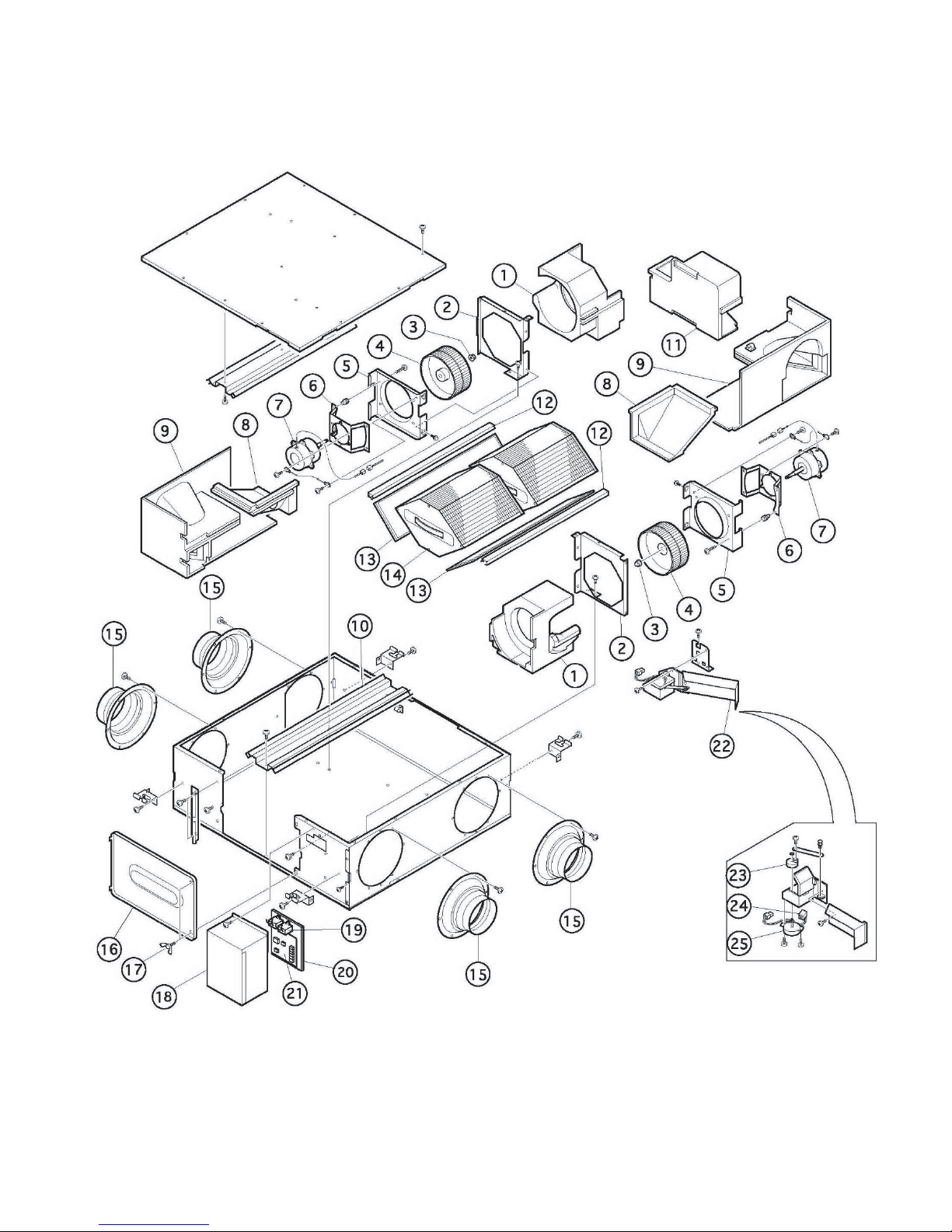
DISASSEMBLY ILLUSTRATION
01
Page 3
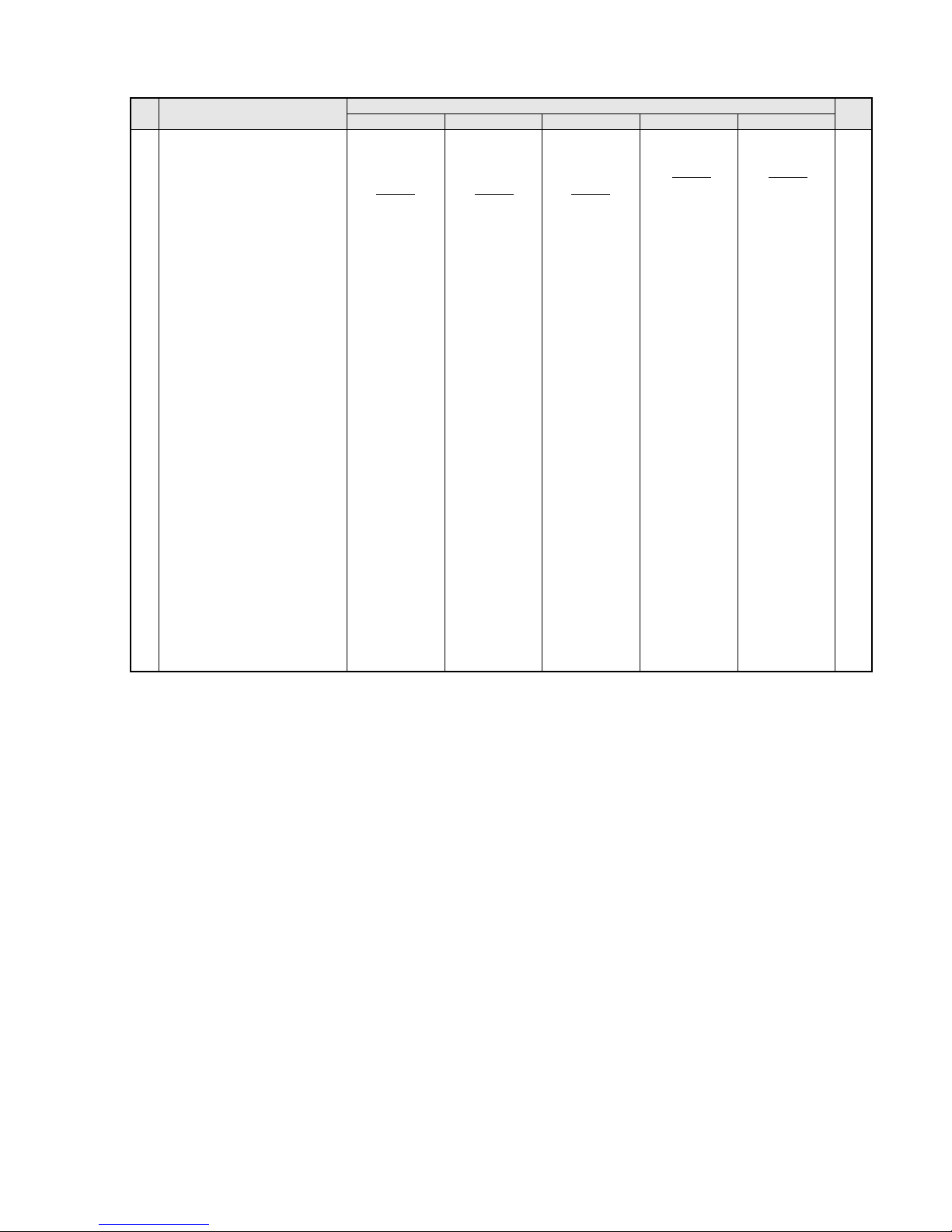
UTZ-BX025A UTZ-BX035A UTZ-BX050A UTZ-BX080A UTZ-BD100A
Parts No.
Description
Ref
No.
Q'ty
1
2
3
3
4
5
6
7
8
9
10
11
12
13
14
15
16
17
18
19
20
21
22
23
24
25
FFV082F078FFV082F074 FFV082F075 FFV082F076 FFV082F078
FFV119F247FFV119F244 FFV119F244 FFV119F245
FFV210F009 FFV210F009 FFV210F010
FFV119F214 FFV119F214 FFV119F215
FFV119F217 FFV119F218 FFV119F219
FFV322F449 FFV322F450 FFV322F451
FBV126F016 FBV126F016 FBV126F016
FFV119F247
FFV119F223FFV119F223
FFV180F069 FFV180F075 FFV180F076
FFV180F079FFV180F078
FFV180F068 FFV180F070 FFV180F071
FFV180F074FFV180F073
FFV180F083 FFV180F083 FFV180F083
FFV180F083FFV180F083
FFV211F235 FFV211F235 FFV211F235
FFV211F235FFV211F235
FFV211F237 FFV211F238 FFV211F239
FFV211F236FFV211F240
FFV212F029 FFV212F029 FFV212F029
FFV212F030FFV212F030
FFV115F190 FFV115F191 FFV115F191
FFV115F193FFV115F192
FFV131F225 FFV131F225 FFV131F225
FFV131F225FFV131F225
UTZ50A-T UTZ50A-T UTZ50A-T
UTZ50A-TUTZ50A-T
UTZ50A-K UTZ50A-K UTZ50A-K
UTZ50A-KUTZ50A-K
UTZ50A-M UTZ50A-M UTZ50A-M
UTZ50A-MUTZ50A-M
UTZ50A-TL UTZ50A-TL UTZ50A-TL
UTZ80A-TLUTZ80A-TL
UTZ25A-PC UTZ35A-PC UTZ50A-PC
UTZD100A-PCUTZ80A-PC
FFV322F448G FFV322F448G FFV322F448G FFV322F448G FFV322F448G
FBV0080031 FBV0080031 FBV0080031
FBV0080031FBV0080031
FFV090F187 FFV090F188 FFV090F189
FFV090F191FFV090F190
FFV180F080 FFV180F080 FFV180F080
FFV180F082FFV180F082
FFV025F037 FFV025F038 FFV025F039
FFV025F041FFV025F040
FFV025F024 FFV025F025 FFV025F026
FFV025F050FFV025F049
FFV027F089 FFV027F088 FFV027F090
FFV027F091FFV027F091
FFV005F083 FFV005F083 FFV005F084
FFV005F085FFV005F085
FFV218F061 FFV218F061 FFV218F061
FFV218F062FFV218F062
FFV251F140 FFV251F141 FFV251F142
FFV251F145FFV251F144
FFV119F221FFV119F220
FFV020F001AFFV020F001A
FFV210F011AFFV210F011A
FFV322F453AFFV322F452A
PARTS LIST
02
CASING
CASING PLATE
NUT,DOME,CAP
NUT,DOME,CAP
FAN,SIROCCO
CASING PARTITION
MOTOR PLATE
MOTOR
PARTITION
AIR PATH UNIT
RAIL
BYPASS UNIT
FILTER RAIL
FILTER
HEAT EXCHANGER
ADAPTOR
LID MAINTENANCE
THUMBSCREW
LID,ELECTRIC PARTS
CAPACITOR
WIRE ASSY
PC BOARD ASSY
DAMPER ASSY
DAMPER CAM
SWITCH,LIMIT
MOTOR DAMPER
OWNER'S MANUAL
INSTALLATION MANUAL
SERVICE MANUAL
WIRING DIAGRAM
PACKING
Page 4

1. Method of remove the Heat Exchange Element and the filter
1: Stop operation and cut the power supply (breaker)
(The left picture shows UTZ-BX050A.)
2: Turn the knob (2 pieces) and the screw (1 piece)
and remove the Inspection Cover.
For UTZ-BX025A/ 035A/ 050A For UTZ-BX080A/ BD100A
3: Remove the filter and the Heat Exchange Element.
Note) The quantity and form of Heat Exchange Element differ depending on the model.
The quantity of Heat Exchange Element by Model
Note: There are differences in the form of Heat Exchange
Element between No.1 No.3 and No.4 No.5.
Refer to the upper pictures.
Inspection
Cover
Electrical
Equipment
Box
Heat
Exchange
Element
Filter
Knob
Screw
DISASSEMBLY INSTRUCTION
Heat
Exchange
Element
Filter
03
1 UTZ-BX025A 1 2
2 UTZ-BX035A 2 2
3 UTZ-BX050A 2 2
4 UTZ-BX080A 3 2
5 UTZ-BD100A 4 2
No Model Number of Number of
Elements Filters
Page 5

2. Method of remove the Motor Assembly
04
3: Pull the partition board A out to the direction of arrow.
1: Remove the filter and the Heat Exchange Element.
Refer to the attached "Method of remove the Heat
Exchange Element and the filter".
2: First remove the screw (1 piece) and then remove
the Grooved Rail.
5: Unhook the Motor ASSY.
4: Turn two pieces of screw on the Motor ASSY
and remove the wired connector.
Connector
Screw
Grooved Rail
Partition Board
Hook
Page 6

05
6: Rotate the Motor ASSY around the axis.
7: Pull it out to the direction of arrow and
put outside of product.
Page 7

3. Method of remove the parts of Electrical Equipment
06
1: First remove the screw (2 pieces) and then remove
the cover of Electrical Equipment Box.
2: Inside of the Electrical Equipment Box.
4: Put outside of product.
1: Remove the wired connector and the screw (1 piece).
2: Slide the damper unit to the direction of arrow.
3: It is removed when pulling to the diretion of arrow 2.
Damper Unit
Connector
Screw
Electrical
Equipment
Box
Screw
Capacitor
Main PCB
4. Method of remove the parts of Electrical Equipment
1
2
Page 8

1116, Suenaga, Takatsu-ku, Kawasaki 213-8502, Japan
0902G3629
 Loading...