

Page 1
DTO_ERV002E_01
2013.04.26
DESIGN & TECHNICAL MANUAL
UTZ-BD025B
UTZ-BD035B
UTZ-BD050B
UTZ-BD080B
UTZ-BD100B
ENERGY RECOVERY VENTILATORS
Page 2

CONTENTS
1. SPECIFICATIONS
1-1. SPECIFICATIONS ........................................................................
01-01
2. DIMENTIONS
2-1. UTZ-BD025B ................................................................................
01-03
2-2. UTZ-BD035B ................................................................................
01-05
2-3. UTZ-BD050B ................................................................................
01-07
2-4. UTZ-BD080B ................................................................................
01-09
2-5. UTZ-BD100B .................................................................................
01-11
3. WIRING DIAGRAMS
3-1. UTZ-BD025B ................................................................................
01-13
3-2. UTZ-BD035B, UTZ-BD050B ........................................................
01-13
3-3. UTZ-BD080B, UTZ-BD100B ........................................................
01-14
3-4. INTERLOCKED CONNECTION TO AIR CONDITIONER ............
01-15
Page 3

4. DESIGN SECTION
4-1. ABOUT HEAT EXCHANGE UNIT ................................................
01-17
4-1-1. BASIC ENGIN .........................................................................................
01-17
4-1-2. INTERNAL STRUCTURE .......................................................................
01-18
4-1-3. HEAT EXCHANGE VENTILATION AND NORMAL VENTILATION .......
01-19
4-2. NEEDS FOR VENTILATION .........................................................
01-20
4-2-1. OBJECTIVES AND EFFECTS OF VENTILATION .................................
01-20
4-3. METHODS OF VENTILATION ......................................................
01-21
4-4. DESIGN PRECAUTIONS .............................................................
01-22
4-4-1. CAUTION ON SAFETY ...........................................................................
01-22
4-4-2. INSPECTION OPENING AND INSTALLATION MODELS .....................
01-23
4-4-3. USE ENVIRONMENTS ...........................................................................
01-24
4-4-4. HEAT EXCHANGE EFFICIENCY ...........................................................
01-25
4-4-5. DUST COLLECTION EFFICIENCY ........................................................
01-27
4-4-6. NOISE .....................................................................................................
01-28
4-4-7. NOISE CONTROL ...................................................................................
01-29
4-5. VENTILATION DESIGN ................................................................
01-31
4-5-1. QUANTITY, DYNAMIC PRESSURE / STATIC PRESSURE ....................
01-31
4-5-2.
HOW TO CALCULATE REQUIRED VENTILATION VOLUME .................
01-32
4-6. DUCT DESIGN ..............................................................................
01-33
4-6-1. CALCULATION OF PRESSURE LOSSES DUE TO VENTILATION
THROUGH DUCT ....................................................................................
01-33
Page 4
- (01-01) -
1. SPECIFICATIONS
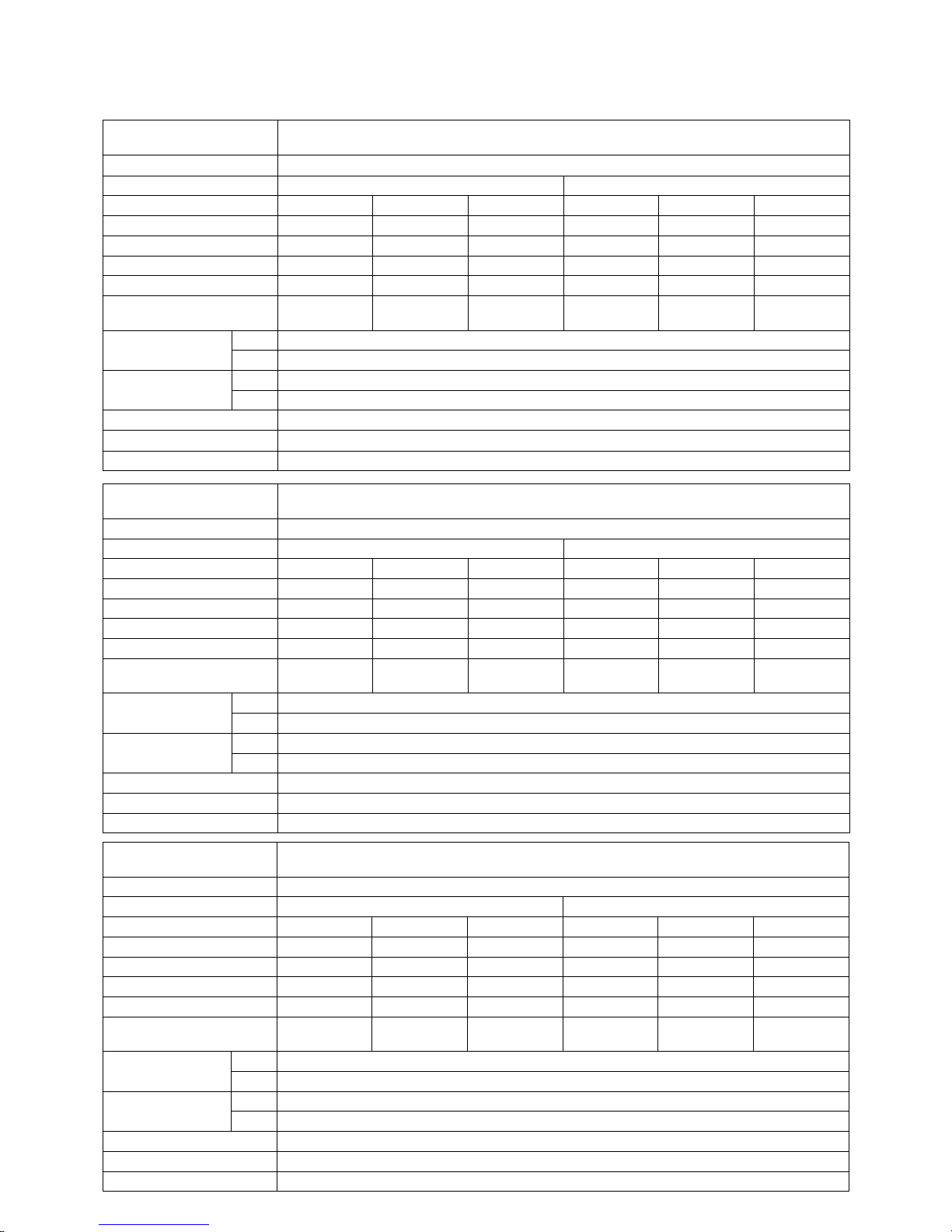
1-1. SPECIFICATIONS
Model No.
Item
UTZ-BD025B
Power Source 220–240V~ 50Hz
Ventilation Mode Heat Exchange Ventilation Normal Ventilation
Notch (Extra high) High Low (Extra high) High Low
Input (W) 112-128 108-123 87-96 112-128 108-123 87-96
Air Volume (m3/h) 250 250 190 250 250 190
External Static Pressure (Pa) 105 95 45 105 95 45
Sound Pressure Level (dB) 30.0-31.5 29.5-30.5 23.5-26.5 30.0-31.5 29.5-30.5 23.5-26.5
Temperature Exchange
Efciency (%)
75 75 77 — — —
Dimensions (mm)
(H x W x D)
Net 270 x 882 x 599
Gross 349 x 1132 x 795
Weight (kg)
Net 29
Gross 35
Outlet Duct Diameter (mm) 150
Operation Range (°C) -10 to 40
Maximum Humidity (%) 85
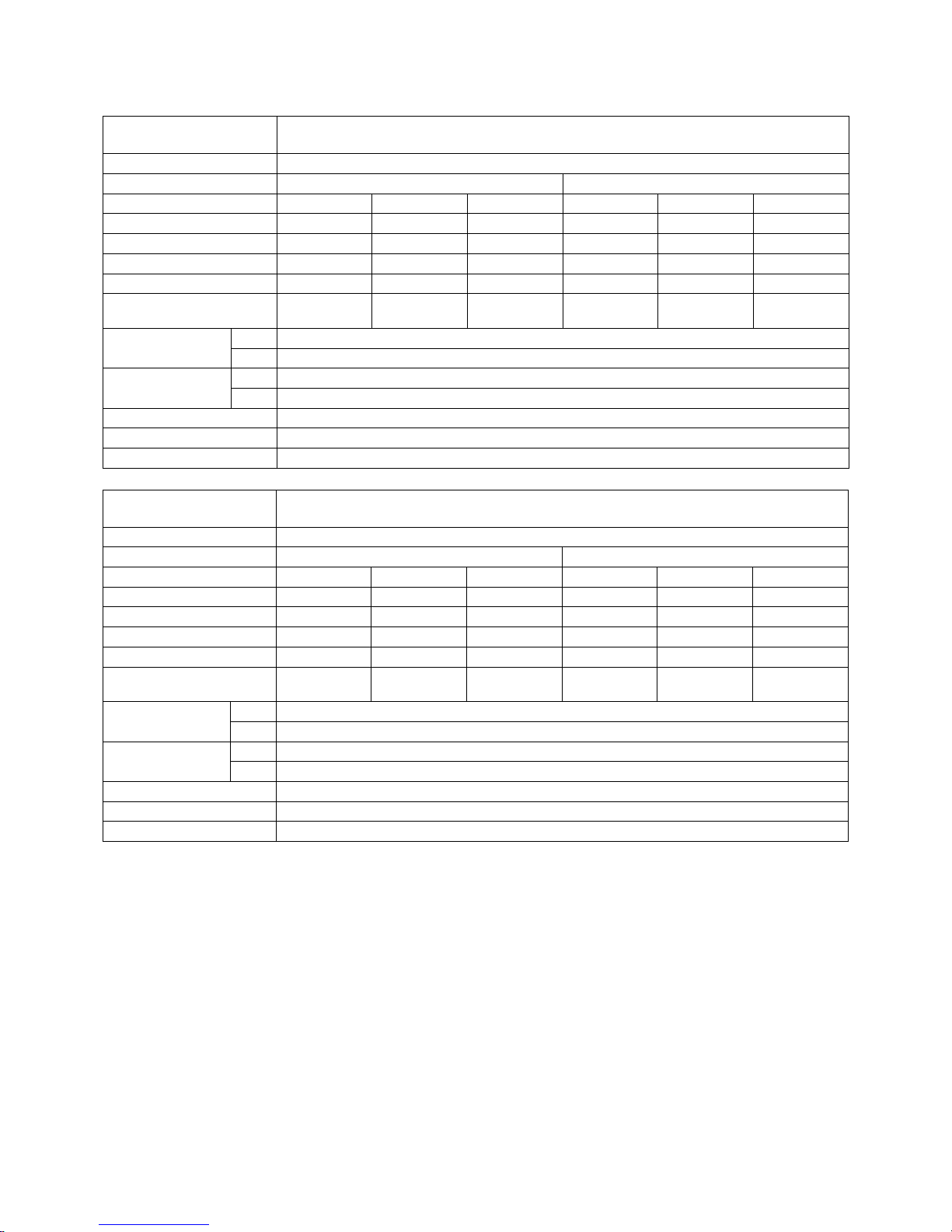
Model No.
Item
UTZ-BD035B
Power Source 220–240V~ 50Hz
Ventilation Mode Heat Exchange Ventilation Normal Ventilation
Notch (Extra high) High Low (Extra high) High Low
Input (W) 182-190 178-185 168-175 182-190 178-185 168-175
Air Volume (m3/h) 350 350 240 350 350 240
External Static Pressure (Pa) 140 60 45 140 60 45
Sound Pressure Level (dB) 32.5-33.0 30.5-31.0 22.5-25.5 32.5-33.0 30.5-31.0 22.5-25.5
Temperature Exchange
Efciency (%)
75 75 78 — — —
Dimensions (mm)
(H x W x D)
Net 317 x 1050 x 804
Gross 396 x 1250 x 1000
Weight (kg)
Net 49
Gross 57
Outlet Duct Diameter (mm) 150
Operation Range (°C) -10 to 40
Maximum Humidity (%) 85
Model No.
Item
UTZ-BD050B
Power Source 220–240V~ 50Hz
Ventilation Mode Heat Exchange Ventilation Normal Ventilation
Notch (Extra high) High Low (Extra high) High Low
Input (W) 263-289 204-225 165-185 263-289 204-225 165-185
Air Volume (m3/h) 500 500 440 500 500 440
External Static Pressure (Pa) 120 60 35 120 60 35
Sound Pressure Level (dB) 36.5-37.5 34.5-35.5 31.0-32.5 36.5-37.5 34.5-35.5 31.0-32.5
Temperature Exchange
Efciency (%)
75 75 76 — — —
Dimensions (mm)
(H x W x D)
Net 317 x 1090 x 904
Gross 396 x 1290 x 1100
Weight (kg)
Net 57
Gross 66
Outlet Duct Diameter (mm) 200
Operation Range (°C) -10 to 40
Maximum Humidity (%) 85
Page 5
- (01-02) -
Model No.
Item
UTZ-BD080B
Power Source 220–240V~ 50Hz
Ventilation Mode Heat Exchange Ventilation Normal Ventilation
Notch (Extra high) High Low (Extra high) High Low
Input (W) 387-418 360-378 293-295 387-418 360-378 293-295
Air Volume (m3/h) 800 800 630 800 800 630
External Static Pressure (Pa) 140 110 55 140 110 55
Sound Pressure Level (dB) 37.0-37.5 36.5-37.0 33.5-34.5 37.0-37.5 36.5-37.0 33.5-34.5
Temperature Exchange
Efciency (%)
75 75 76 — — —
Dimensions (mm)
(H x W x D)
Net 388 x 1322 x 884
Gross 467 x 1552 x 1170
Weight (kg)
Net 71
Gross 82
Outlet Duct Diameter (mm) 250
Operation Range (°C) -10 to 40
Maximum Humidity (%) 85
Model No.
Item
UTZ-BD100B
Power Source 220–240V~ 50Hz
Ventilation Mode Heat Exchange Ventilation Normal Ventilation
Notch (Extra high) High Low (Extra high) High Low
Input (W) 437-464 416-432 301-311 437-464 416-432 301-311
Air Volume (m3/h) 1000 1000 700 1000 1000 700
External Static Pressure (Pa) 105 80 75 105 80 75
Sound Pressure Level (dB) 37.5-38.5 37.0-37.5 33.5-34.5 39.5-40.5 39.0-39.5 35.5-36.5
Temperature Exchange
Efciency (%)
75 75 76 — — —
Dimensions (mm)
(H x W x D)
Net 388 x 1322 x 1134
Gross 467 x 1552 x 1420
Weight (kg)
Net 83
Gross 98
Outlet Duct Diameter (mm) 250
Operation Range (°C) -10 to 40
Maximum Humidity (%) 85
(Note) This noise of the product is the value which was measured at the acoustic room.
Actually, in the established condition, that undergo inuence by the echoing of the room and so that become bigger
than the display numerical value.
Page 6

- (01-03) -
2. DIMENTIONS
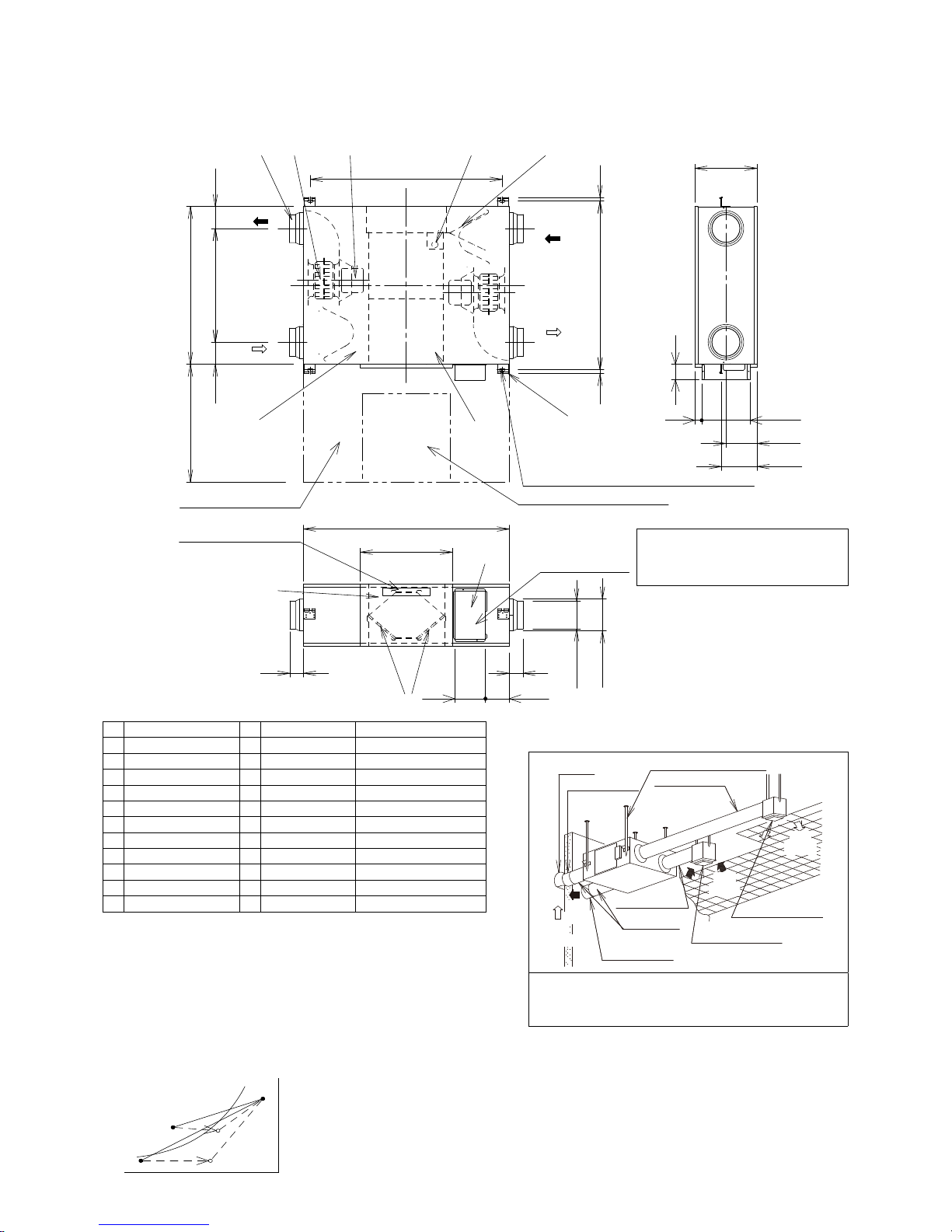
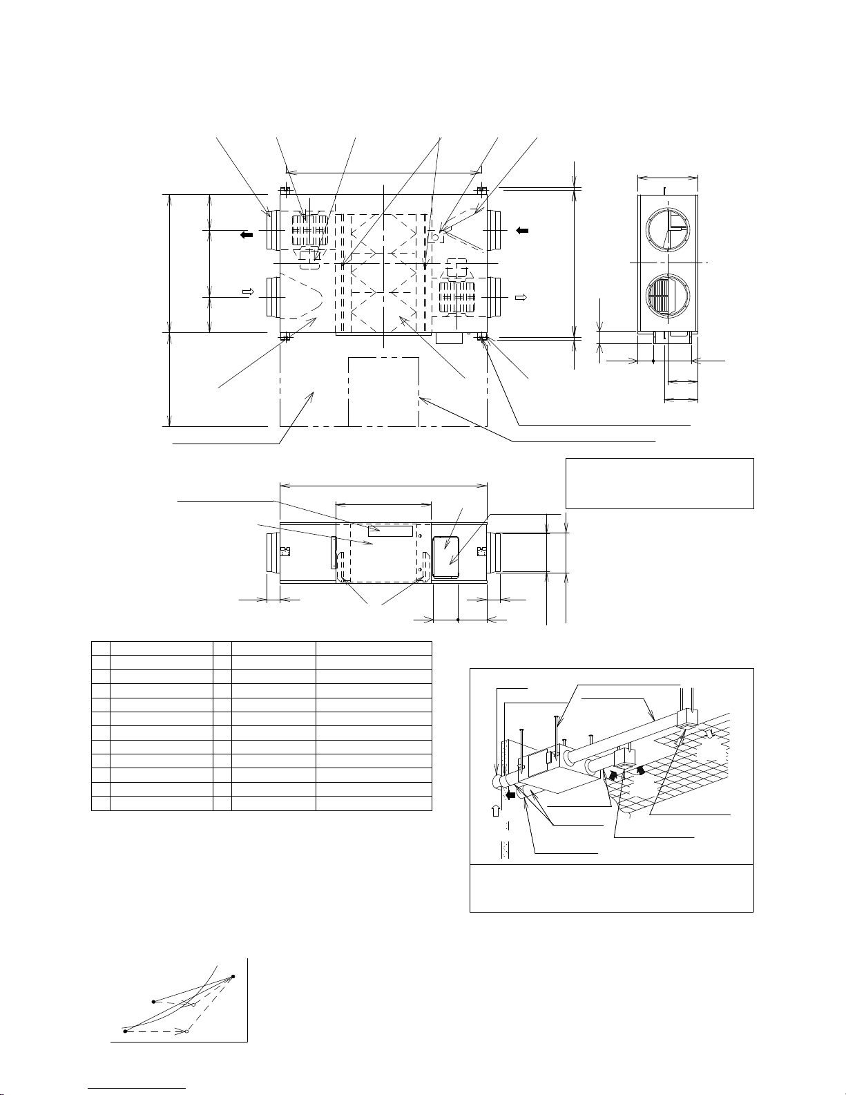
2-1. UTZ-BD025B
NO.
Parts Name
Qty.
Material Remarks
1
Frame
1
Galvanized sheets
2
Adapter
4
ABS
3
Electrical Equipment Box
1
4
Inspection Cover
1
Galvanized sheets
5
Fan
2
ABS
6
Motor
2
7
Heat Exchange Element1Special paper + Resin
8
Filter
2
Nylon-Polyester Fiber Collection Efciency AFI 82%
9
Damper
1
10
Damper Motor
1
11
Ceiling Suspension Fixture4Galvanized sheets
BE CAREFUL OF DEWING AND
FROSTING
As shown in the Figure, suppose a high temp absorbing air condition
A and a low temp absorbing air condition B are plotted on the air line
gure, then a high temp air A is heat-exchanged by the unit and goes
out of the saturation curve as shown by Point C.
In this case, the unit will be dewed or frosted.
To aboid this, you are required to heat a low temp air B up to B’ so as
to get C’ below the saturation curve, before using the unit.
saturationcurve
Dry-bulb temperature(˚C)
Absolite humidity (kg/kg’)
C’
C
B
B’
A
REFERENCE SKETCH
Pipe Hood
Outside Intake Duct
Ceilling Suspension Bolts
Supply Air Duct
EA
(Exhaust
Air)
OA
(Outside intake Air)
RA
(Room Air)
SA
(Supply Air)
Inside Supply Opening
(Supply/Exhaust Air Grill)
Room Intake Opening
(Supply/Exhaust Air Grill)
Room Intake Duct
Heat Insulation Material
Exhaust Air Duct
The two outside ducts(the Outside Intake Duct and the
Exhaust Duct)must be insulated to prevent condensation.
(Material; Glass wool, Thickness; 25)
Duct size (Nominal Diameter): ø150
The above dimensions do not include the thickness of
the insulasion material on the unit body.
② ⑤ ⑥ ⑩ ⑨
①
⑦
⑪
599600
142 315 142
EA
OA
(Exhaust Air)
(Outside Air)
810
Maintenance Space
Inspection Opening □450
(For the inspection of the lters, heat exchange elements, fans, motors, and damper)
4-13×30 Oval hole · Suspension Fittings
1965519
RA
SA
(Room Air)
(Supply Air)
An inspection opening is necessary to
clean the heat exchange element and
lter once or twice a year.
270
247
159
135
12
80
④
⑧
③
882
414
95
95
Wiring Diagram
Earth Terminal
Ø219
Ø164
Ø144
67
157
Page 7
- (01-04) -
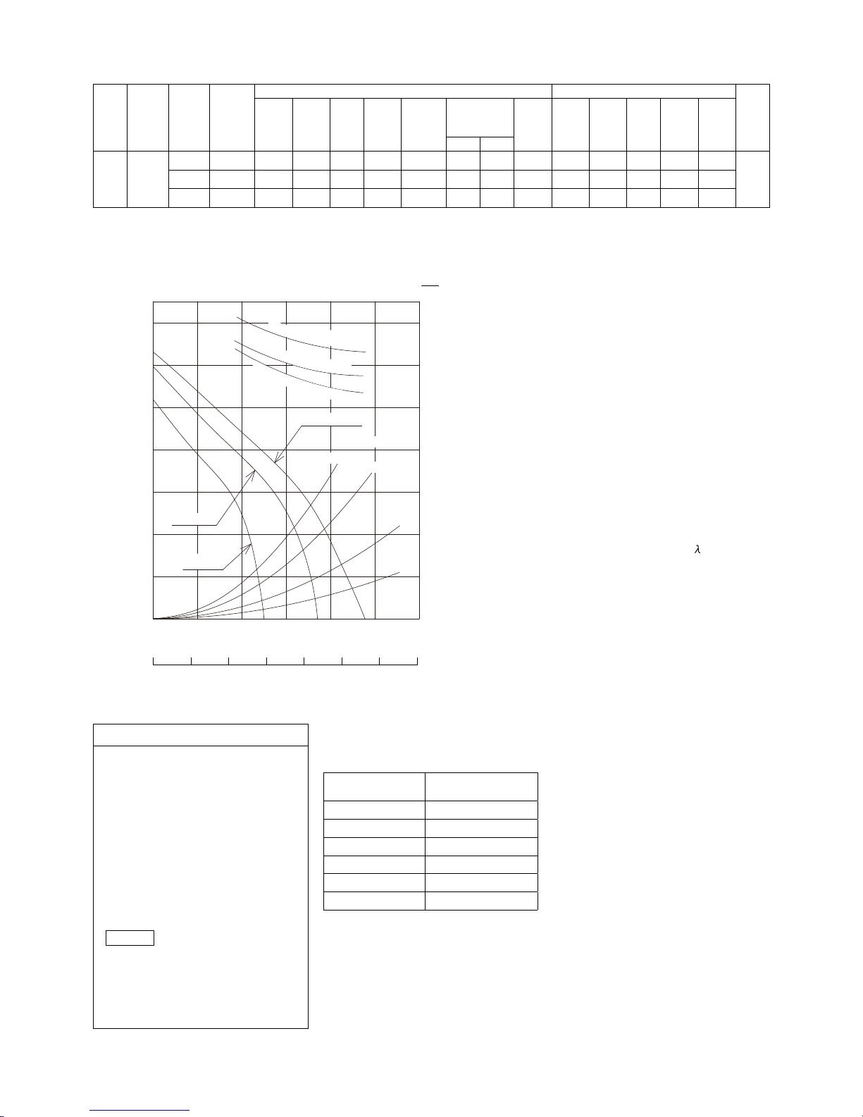
SPECIFICATIONS
Model
No.
Power
Source
Notch
Frequency
Heat Exchange Ventilation Normal Ventilation
Product
Weight
Input Current
Air
Volume
External
Static
Pressure
Temperature
Exchange
Efciency
Enthalpy
Exchange
Efciency (%)
Noise Input Current
Air
Volume
External
Static
Pressure
Noise
(Hz) (W) (A) (m3/h) (Pa) (%) Cooling Heating (dB) (W) (A) (m3/h) (Pa) (dB) (kg)
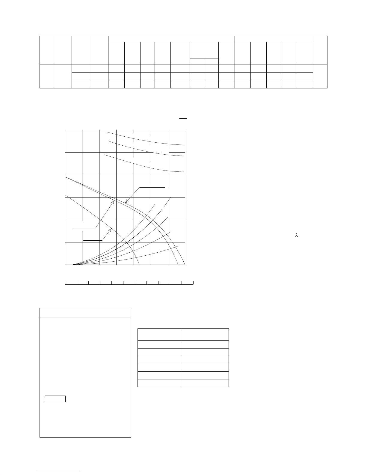
UTZ-
BD025B
220-240V
a.c.
Extra High
50 112-128 0.51-0.53 250 105 75 63 70 30.0-31.5 112-128 0.51-0.53 250 105 30.0-31.5
29
High
50 108-123 0.49-0.51 250 95 75 63 70 29.5-30.5 108-123 0.49-0.51 250 95 29.5-30.5
Low
50 87-96 0.40-0.41 190 45 77 65 72 23.5-26.5 87-96 0.40-0.41 190 45 23.5-26.5
This noise of the product is the value which was measured at the acoustic room. Actually, in the established condition, that undergo inuence
by the echoing of the room and so that become bigger than the display numerical value .
PERFORMANCE
Use conditions
Outdoor air conditions
Temperature range -10˚C ~ 40˚C
Relative humidity 85% or less
Indoor air conditions
Temperature range -10˚C ~ 40˚C
Relative humidity 85% or less
Installation requirements
Same as the indoor air conditions
*
Indoor air here means air in air-conditioned
living rooms.
Its use in refrigerators or other place s
where temperature can uctuate greatly is
prohibited even if a temperature range is
acceptable.
Example
Indoor air conditions
During cooling period
Temperature 27˚C
Relative humidity 50%
During heating period
Temperature 20˚C
Relative humidity 40%
• The Input, the current and the exchange
efficiency are values at the time of the
mentioned air volume.
• The noise level shall be measured 1.5m
below the center of the unit.
• Th e temp erat ure exch ange effic ienc y
averages that of when cooling and when
heating.
MOTOR
SPECIFICATIONS
Type
4 Poles open type
induction motor
Rating Cont.
Insulation Class class E
Temperature Rise under 75 K
Sorrounding Temperature
-10˚C ~ 40˚C
Insulation Resistance
over 1MΩ (by DC500V)
Withstand Voltage AC 1,500V for 1min
300
0 50 100 150 200 250 300 350
50
100
150
200
250
0 20 40 60 80 100 120 140 160 180 200 220
Air Volume (m
3
/h)
Air Volume (ft
3
/min)
External Static Pressure (Pa)
80
50
60
70
Exchange Efciency (%)
Duct resistance Curve
P-Q Curve
220 - 240V ~ 50HzEfciency Curve
T
e
m
pe
ra
t
u
r
e
E
nt
h
al
p
y
(i
n
h
e
a
t
i
n
g
)
E
nt
h
al
p
y
(i
n
c
o
o
li
n
g
)
Extra High
Equivalent pipe length
High
Low
When friction coefcient of pipe (duct) :
=0.02
100m
80
60
20
40
Page 8
- (01-05) -
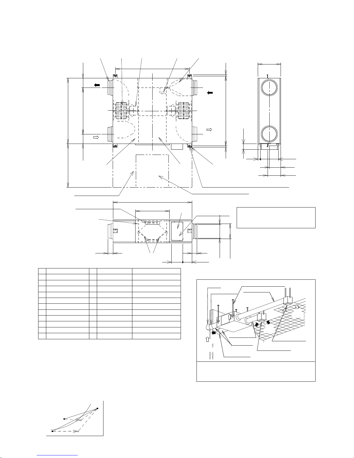
2-2. UTZ-BD035B
NO.
Parts Name
Qty.
Material Remarks
1
Frame
1
Galvanized sheets
2
Adapter
4
ABS
3
Electrical Equipment Box
1
4
Inspection Cover
1
Galvanized sheets
5
Fan
2
ABS
6
Motor
2
7
Heat Exchange Element2Special paper + Resin
8
Filter
2
Nylon-Polyester Fiber Collection Efciency AFI 82%
9
Damper
1
10
Damper Motor
1
11
Ceiling Suspension Fixture4Galvanized sheets
BE CAREFUL OF DEWING AND
FROSTING
As shown in the Figure, suppose a high temp absorbing air condition
A and a low temp absorbing air condition B are plotted on the air line
gure, then a high temp air A is heat-exchanged by the unit and goes
out of the saturation curve as shown by Point C.
In this case, the unit will be dewed or frosted.
To aboid this, you are required to heat a low temp air B up to B’ so as
to get C’ below the saturation curve, before using the unit.
saturationcurve
Dry-bulb temperature(˚C)
Absolite humidity (kg/kg’)
C’
C
B
B’
A
REFERENCE SKETCH
Pipe Hood
Outside Intake Duct
Ceilling Suspension Bolts
Supply Air Duct
EA
(Exhaust
Air)
OA
(Outside intake Air)
RA
(Room Air)
SA
(Supply Air)
Inside Supply Opening
(Supply/Exhaust Air Grill)
Room Intake Opening
(Supply/Exhaust Air Grill)
Room Intake Duct
Heat Insulation Material
Exhaust Air Duct
The two outside ducts(the Outside Intake Duct and the
Exhaust Duct)must be insulated to prevent condensation.
(Material;Glass wool, Thickness;25)
Duct size (Nominal Diameter): ø150
The above dimensions do not include the thickness of
the insulasion material on the unit body.
978
② ⑤ ⑥
⑩
⑨
①
⑦
⑪
804600
112 580 112
EA
OA
(Exhaust Air)
(Outside Air)
Maintenance Space
Inspection Opening □450
(For the inspection of the lters, heat exchange elements, fans, motors, and damper)
4-13×30 Oval hole · Suspension Fittings
1986019
RA
SA
(Room Air)
(Supply Air)
An inspection opening is necessary to
clean the heat exchange element and
lter once or twice a year.
317
247
182
159
35
80
④
⑧
③
1050
470
70
70
Wiring Diagram
Earth Terminal
Ø162
Ø144
122
157
Page 9
- (01-06) -
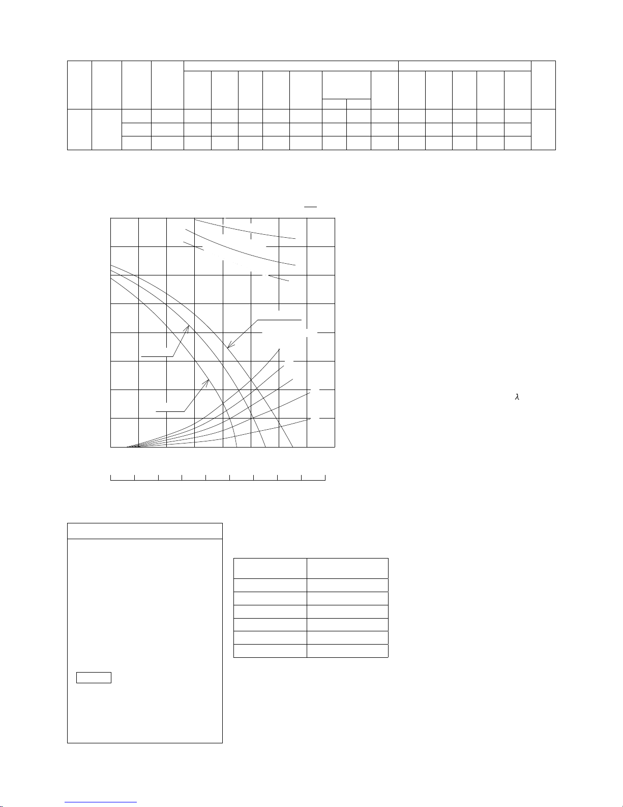
SPECIFICATIONS
Model
No.
Power
Source
Notch
Frequency
Heat Exchange Ventilation Normal Ventilation
Product
Weight
Input Current
Air
Volume
External
Static
Pressure
Temperature
Exchange
Efciency
Enthalpy
Exchange
Efciency (%)
Noise Input Current
Air
Volume
External
Static
Pressure
Noise
(Hz) (W) (A) (m3/h) (Pa) (%) Cooling Heating (dB) (W) (A) (m3/h) (Pa) (dB) (kg)
UTZ-
BD035B
220-240V
a.c.
Extra High
50 182-190 0.63-0.65 350 140 75 66 69 32.5-33.0 182-190 0.63-0.65 350 140 32.5-33.0
49
High
50 178-185 0.59-0.60 350 60 75 66 69 30.5-31.0 178-185 0.59-0.60 350 60 30.5-31.0
Low
50 168-175 0.56-0.57 240 45 78 71 73 22.5-25.5 168-175 0.56-0.57 240 45 22.5-25.5
This noise of the product is the value which was measured at the acoustic room. Actually, in the established condition, that undergo inuence
by the echoing of the room and so that become bigger than the display numerical value .
PERFORMANCE
Use conditions
Outdoor air conditions
Temperature range -10˚C ~ 40˚C
Relative humidity 85% or less
Indoor air conditions
Temperature range -10˚C ~ 40˚C
Relative humidity 85% or less
Installation requirements
Same as the indoor air conditions
*
Indoor air here means air in air-conditioned
living rooms.
Its use in refrigerators or other place s
where temperature can uctuate greatly is
prohibited even if a temperature range is
acceptable.
Example
Indoor air conditions
During cooling period
Temperature 27˚C
Relative humidity 50%
During heating period
Temperature 20˚C
Relative humidity 40%
• The Input, the current and the exchange
efficiency are values at the time of the
mentioned air volume.
• The noise level shall be measured 1.5m
below the center of the unit.
• Th e temp erat ure exch ange effic ienc y
averages that of when cooling and when
heating.
MOTOR
SPECIFICATIONS
Type
4 Poles open type
induction motor
Rating Cont.
Insulation Class class E
Temperature Rise under 75 K
Sorrounding Temperature
-10˚C ~ 40˚C
Insulation Resistance
over 1MΩ (by DC500V)
Withstand Voltage AC 1,500V for 1min
350
0 100 200 300 400 500 600
50
100
150
200
300
0 50 100 150 200 250 300 350
Air Volume (m
3
/h)
Air Volume (ft
3
/min)
External Static Pressure (Pa)
80
50
60
70
Exchange Efciency (%)
Duct resistance Curve
P-Q Curve 220 - 240V ~ 50HzEfciency Curve
T
e
m
p
e
r
a
t
u
r
e
E
n
t
h
a
l
p
y
(
i
n
h
e
a
t
i
n
g
)
E
n
t
h
a
l
p
y
(
i
n
c
o
o
l
i
n
g
)
Extra High
Equivalent pipe length
High
Low
When friction coefcient of pipe (duct) :
=0.02
60m
40
20
250
10
Page 10
- (01-07) -
2-3. UTZ-BD050B
NO.
Parts Name
Qty.
Material Remarks
1
Frame
1
Galvanized sheets
2
Adapter
4
Galvanized sheets
3
Electrical Equipment Box
1
4
Inspection Cover
1
Galvanized sheets
5
Fan
2
ABS
6
Motor
2
7
Heat Exchange Element2Special paper + Resin
8
Filter
2
Nylon-Polyester Fiber Collection Efciency AFI 82%
9
Damper
1
10
Damper Motor
1
11
Ceiling Suspension Fixture4Galvanized sheets
BE CAREFUL OF DEWING AND
FROSTING
As shown in the Figure, suppose a high temp absorbing air condition
A and a low temp absorbing air condition B are plotted on the air line
gure, then a high temp air A is heat-exchanged by the unit and goes
out of the saturation curve as shown by Point C.
In this case, the unit will be dewed or frosted.
To aboid this, you are required to heat a low temp air B up to B’ so as
to get C’ below the saturation curve, before using the unit.
saturationcurve
Dry-bulb temperature(˚C)
Absolite humidity (kg/kg’)
C’
C
B
B’
A
REFERENCE SKETCH
Pipe Hood
Outside Intake Duct
Ceilling Suspension Bolts
Supply Air Duct
EA
(Exhaust
Air)
OA
(Outside intake Air)
RA
(Room Air)
SA
(Supply Air)
Inside Supply Opening
(Supply/Exhaust Air Grill)
Room Intake Opening
(Supply/Exhaust Air Grill)
Room Intake Duct
Heat Insulation Material
Exhaust Air Duct
The two outside ducts(the Outside Intake Duct and the
Exhaust Duct)must be insulated to prevent condensation.
(Material;Glass wool, Thickness;25)
Duct size (Nominal Diameter): ø200
The above dimensions do not include the thickness of
the insulasion material on the unit body.
②
⑤
⑥
⑩
⑨
①
⑦
⑪
904600
132 640 132
EA
OA
(Exhaust Air)
(Outside Air)
1018
Maintenance Space
Inspection Opening □450
(For the inspection of the lters, heat exchange elements, fans, motors, and damper)
4-13×30 Oval hole · Suspension Fittings
1996019
RA
SA
(Room Air)
(Supply Air)
An inspection opening is necessary to
clean the heat exchange element and
lter once or twice a year.
317
159
182
247
35
80
④
⑧
③
1090
470
127
70
Wiring Diagram
Earth Terminal
Ø210
Ø194
157
70
Page 11
- (01-08) -
SPECIFICATIONS
Model
No.
Power
Source
Notch
Frequency
Heat Exchange Ventilation Normal Ventilation
Product
Weight
Input Current
Air
Volume
External
Static
Pressure
Temperature
Exchange
Efciency
Enthalpy
Exchange
Efciency (%)
Noise Input Current
Air
Volume
External
Static
Pressure
Noise
(Hz) (W) (A) (m3/h) (Pa) (%) Cooling Heating (dB) (W) (A) (m3/h) (Pa) (dB) (kg)
UTZ-
BD050B
220-240V
a.c.
Extra High
50 263-289 1.20-1.21 500 120 75 62 67 36.5-37.5 263-289 1.20-1.21 500 120 36.5-37.5
57
High
50 204-225 0.93-0.94 500 60 75 62 67 34.5-35.5 204-225 0.93-0.94 500 60 34.5-35.5
Low
50 165-185 0.75-0.77 440
35
76 64 69 31.0-32.5 165-185 0.75-0.77 440
35
31.0-32.5
This noise of the product is the value which was measured at the acoustic room. Actually, in the established condition, that undergo inuence
by the echoing of the room and so that become bigger than the display numerical value .
PERFORMANCE
Use conditions
Outdoor air conditions
Temperature range -10˚C ~ 40˚C
Relative humidity 85% or less
Indoor air conditions
Temperature range -10˚C ~ 40˚C
Relative humidity 85% or less
Installation requirements
Same as the indoor air conditions
*
Indoor air here means air in air-conditioned
living rooms.
Its use in refrigerators or other place s
where temperature can uctuate greatly is
prohibited even if a temperature range is
acceptable.
Example
Indoor air conditions
During cooling period
Temperature 27˚C
Relative humidity 50%
During heating period
Temperature 20˚C
Relative humidity 40%
• The Input, the current and the exchange
efficiency are values at the time of the
mentioned air volume.
• The noise level shall be measured 1.5m
below the center of the unit.
• Th e temp erat ure exch ange effic ienc y
averages that of when cooling and when
heating.
MOTOR
SPECIFICATIONS
Type
4 Poles open type
induction motor
Rating Cont.
Insulation Class class E
Temperature Rise under 75 K
Sorrounding Temperature
-10˚C ~ 40˚C
Insulation Resistance
over 1MΩ (by DC500V)
Withstand Voltage AC 1,500V for 1min
400
0 100 200 300 400 500 600 700 800
50
100
150
200
300
0 50 100 150 200 250 300 350 400 450
Air Volume (m
3
/h)
Air Volume (ft
3
/min)
External Static Pressure (Pa)
80
50
60
70
Exchange Efciency (%)
Duct resistance Curve
P-Q Curve
220 - 240V ~ 50HzEfciency Curve
T
e
m
p
e
r
a
t
u
r
e
E
n
t
h
a
l
p
y
(
i
n
h
e
a
t
i
n
g
)
E
n
t
h
a
l
p
y
(
i
n
c
o
o
l
i
n
g
)
Extra High
Equivalent pipe length
High
Low
When friction coefcient of pipe (duct) :
=0.02
100m
60
40
250
20
350
80
Page 12
- (01-09) -
2-4. UTZ-BD080B
NO.
Parts Name
Qty.
Material Remarks
1
Frame
1
Galvanized sheets
2
Adapter
4
Galvanized sheets
3
Electrical Equipment Box
1
4
Inspection Cover
1
Galvanized sheets
5
Fan
2
ABS
6
Motor
2
7
Heat Exchange Element3Special paper + Resin
8
Filter
2
Nylon-Polyester Fiber Collection Efciency AFI 82%
9
Damper
1
10
Damper Motor
1
11
Ceiling Suspension Fixture4Galvanized sheets
BE CAREFUL OF DEWING AND
FROSTING
As shown in the Figure, suppose a high temp absorbing air condition
A and a low temp absorbing air condition B are plotted on the air line
gure, then a high temp air A is heat-exchanged by the unit and goes
out of the saturation curve as shown by Point C.
In this case, the unit will be dewed or frosted.
To aboid this, you are required to heat a low temp air B up to B’ so as
to get C’ below the saturation curve, before using the unit.
saturationcurve
Dry-bulb temperature (˚C)
Absolite humidity (kg/kg’)
C’
C
B
B’
A
REFERENCE SKETCH
Pipe Hood
Outside Intake Duct
Ceilling Suspension Bolts
Supply Air Duct
EA
(Exhaust
Air)
OA
(Outside intake Air)
RA
(Room Air)
SA
(Supply Air)
Inside Supply Opening
(Supply/Exhaust Air Grill)
Room Intake Opening
(Supply/Exhaust Air Grill)
Room Intake Duct
Heat Insulation Material
Exhaust Air Duct
The two outside ducts(the Outside Intake Duct and the
Exhaust Duct)must be insulated to prevent condensation.
(Material;Glass wool, Thickness;25)
Duct size (Nominal Diameter): ø250
The above dimensions do not include the thickness of
the insulasion material on the unit body.
②
⑤
⑥
⑩
⑨
①
⑦
⑪
884600
228 428 228
EA
OA
(Exhaust Air)
(Outside Air)
1250
Maintenance Space
Inspection Opening □450
(For the inspection of the lters, heat exchange elements, fans, motors, and damper)
4-13×30 Oval hole · Suspension Fittings
1994019
RA
SA
(Room Air)
(Supply Air)
⑧
An inspection opening is necessary to
clean the heat exchange element and
lter once or twice a year.
388
194
218
247101
80
④
⑧
③
1322
612
85
85
Wiring Diagram
Earth Terminal
Ø258
Ø242
184157
Page 13

- (01-10) -
SPECIFICATIONS
Model
No.
Power
Source
Notch
Frequency
Heat Exchange Ventilation Normal Ventilation
Product
Weight
Input Current
Air
Volume
External
Static
Pressure
Temperature
Exchange
Efciency
Enthalpy
Exchange
Efciency (%)
Noise Input Current
Air
Volume
External
Static
Pressure
Noise
(Hz) (W) (A) (m3/h) (Pa) (%) Cooling Heating (dB) (W) (A) (m3/h) (Pa) (dB) (kg)
UTZ-
BD080B
220-240V
a.c.
Extra High
50 387-418 1.74-1.76 800 140 75 65 71 37.0-37.5 387-418 1.74-1.76 800 140 37.0-37.5
71
High
50 360-378 1.58-1.64 800 110 75 65 71 36.5-37.0 360-378 1.58-1.64 800 110 36.5-37.0
Low
50 293-295 1.23-1.33 630 55 76 68 74 33.5-34.5 293-295 1.23-1.33 630 55 33.5-34.5
This noise of the product is the value which was measured at the acoustic room .Actually, in the established condition, that undergo inuence
by the echoing of the room and so that become bigger than the display numerical value .
PERFORMANCE
400
0 100 200 300 400 500 600 700 800 900 1000 1100 1200
50
100
150
200
300
0 100 200 300 400 500 600 700
Air Volume (m
3
/h)
Air Volume (ft
3
/min)
External Static Pressure (Pa)
80
50
60
70
Exchange Efciency (%)
Duct resistance Curve
P-Q Curve
220 - 240V ~ 50HzEfciency Curve
T
e
m
p
e
r
a
t
u
r
e
E
n
t
h
a
l
p
y
(
i
n
h
e
a
t
i
n
g
)
E
n
t
h
a
l
p
y
(
i
n
c
o
o
l
i
n
g
)
Extra High
Equivalent pipe length
High
Low
When friction coefcient
of pipe (duct) :
=0.02
100m
60
40
250
20
350
80
90450
500
Use conditions
Outdoor air conditions
Temperature range -10˚C ~ 40˚C
Relative humidity 85% or less
Indoor air conditions
Temperature range -10˚C ~ 40˚C
Relative humidity 85% or less
Installation requirements
Same as the indoor air conditions
*
Indoor air here means air in air-conditioned
living rooms.
Its use in refrigerators or other place s
where temperature can uctuate greatly is
prohibited even if a temperature range is
acceptable.
Example
Indoor air conditions
During cooling period
Temperature 27˚C
Relative humidity 50%
During heating period
Temperature 20˚C
Relative humidity 40%
• The Input, the current and the exchange
efficiency are values at the time of the
mentioned air volume.
• The noise level shall be measured 1.5m
below the center of the unit.
• Th e temp erat ure exch ange effic ienc y
averages that of when cooling and when
heating.
MOTOR
SPECIFICATIONS
Type
4 Poles open type
induction motor
Rating Cont.
Insulation Class class E
Temperature Rise under 75 K
Sorrounding Temperature
-10˚C ~ 40˚C
Insulation Resistance
over 1MΩ (by DC500V)
Withstand Voltage AC 1,500V for 1min
Page 14

- (01-11) -
2-5. UTZ-BD100B
NO.
Parts Name
Qty.
Material Remarks
1
Frame
1
Galvanized sheets
2
Adapter
4
Galvanized sheets
3
Electrical Equipment Box
1
4
Inspection Cover
1
Galvanized sheets
5
Fan
2
ABS
6
Motor
2
7
Heat Exchange Element4Special paper + Resin
8
Filter
2
Nylon-Polyester Fiber Collection Efciency AFI 82%
9
Damper
1
10
Damper Motor
1
11
Ceiling Suspension Fixture4Galvanized sheets
BE CAREFUL OF DEWING AND
FROSTING
As shown in the Figure, suppose a high temp absorbing air condition
A and a low temp absorbing air condition B are plotted on the air line
gure, then a high temp air A is heat-exchanged by the unit and goes
out of the saturation curve as shown by Point C.
In this case, the unit will be dewed or frosted.
To aboid this, you are required to heat a low temp air B up to B’ so as
to get C’ below the saturation curve, before using the unit.
saturationcurve
Dry-bulb temperature (˚C)
Absolite humidity (kg/kg’)
C’
C
B
B’
A
REFERENCE SKETCH
Pipe Hood
Outside Intake Duct
Ceilling Suspension Bolts
Supply Air Duct
EA
(Exhaust
Air)
OA
(Outside intake Air)
RA
(Room Air)
SA
(Supply Air)
Inside Supply Opening
(Supply/Exhaust Air Grill)
Room Intake Opening
(Supply/Exhaust Air Grill)
Room Intake Duct
Heat Insulation Material
Exhaust Air Duct
The two outside ducts(the Outside Intake Duct and the
Exhaust Duct)must be insulated to prevent condensation.
(Material;Glass wool, Thickness;25)
Duct size (Nominal Diameter): ø250
The above dimensions do not include the thickness of
the insulasion material on the unit body.
②
⑤
⑥
⑩
⑨
①
⑦
⑪
1134600
228 678 228
EA
OA
(Exhaust Air)
(Outside Air)
1250
Maintenance Space
Inspection Opening □450
(For the inspection of the lters, heat exchange elements, fans, motors, and damper)
4-13×30 Oval hole
· Suspension Fittings
19119019
RA
SA
(Room Air)
(Supply Air)
⑧
An inspection opening is necessary to
clean the heat exchange element and
lter once or twice a year.
388
194
218
247101
80
④
⑧
③
1322
612
85
85
Wiring Diagram
Earth Terminal
Ø258
Ø242
157 184
Page 15

- (01-12) -
SPECIFICATIONS
Model
No.
Power
Source
Notch
Frequency
Heat Exchange Ventilation Normal Ventilation
Product
Weight
Input Current
Air
Volume
External
Static
Pressure
Temperature
Exchange
Efciency
Enthalpy
Exchange
Efciency (%)
Noise Input Current
Air
Volume
External
Static
Pressure
Noise
(Hz) (W) (A) (m3/h) (Pa) (%) Cooling Heating (dB) (W) (A) (m3/h) (Pa) (dB) (kg)
UTZ-
BD100B
220-240V
a.c.
Extra High
50 437-464 1.93-1.99 1000 105 75 65 71 37.5-38.5 437-464 1.93-1.99 1000 105 37.5-38.5
83
High
50 416-432 1.80-1.89 1000 80 75 65 71 37.0-37.5 416-432 1.80-1.89 1000 80 37.0-37.5
Low
50 301-311 1.29-1.37 700 75 79 70 76 33.5-34.5 301-311 1.29-1.37 700 75 33.5-34.5
This noise of the product is the value which was measured at the acoustic room. Actually, in the established condition, that undergo inuence
by the echoing of the room and so that become bigger than the display numerical value .
PERFORMANCE
400
0 100 200 300 400 500 600 700 800 900 1000 1100 1200 1300
50
100
150
200
300
0 100 200 300 400 500 600 700
Air Volume (m
3
/h)
Air Volume (ft
3
/min)
External Static Pressure (Pa)
80
50
60
70
Exchange Efciency (%)
Duct resistance Curve
P-Q Curve
220 - 240V ~ 50HzEfciency Curve
T
e
m
p
e
r
a
t
u
r
e
E
n
t
h
a
l
p
y
(
i
n
h
e
a
t
i
n
g
)
E
n
t
h
a
l
p
y
(
i
n
c
o
o
l
i
n
g
)
Extra High
Equivalent pipe length
High
Low
When friction coefcient
of pipe (duct) :
=0.02
100m
60
40
250
20
350
80
90
500
450
Use conditions
Outdoor air conditions
Temperature range -10˚C ~ 40˚C
Relative humidity 85% or less
Indoor air conditions
Temperature range -10˚C ~ 40˚C
Relative humidity 85% or less
Installation requirements
Same as the indoor air conditions
*
Indoor air here means air in air-conditioned
living rooms.
Its use in refrigerators or other place s
where temperature can uctuate greatly is
prohibited even if a temperature range is
acceptable.
Example
Indoor air conditions
During cooling period
Temperature 27˚C
Relative humidity 50%
During heating period
Temperature 20˚C
Relative humidity 40%
• The Input, the current and the exchange
efficiency are values at the time of the
mentioned air volume.
• The noise level shall be measured 1.5m
below the center of the unit.
• Th e temp erat ure exch ange effic ienc y
averages that of when cooling and when
heating.
MOTOR
SPECIFICATIONS
Type
4 Poles open type
induction motor
Rating Cont.
Insulation Class class E
Temperature Rise under 75 K
Sorrounding Temperature
-10˚C ~ 40˚C
Insulation Resistance
over 1MΩ (by DC500V)
Withstand Voltage AC 1,500V for 1min
Page 16

- (01-13) -
3. WIRING DIAGRAMS
3-1. UTZ-BD025B
SW1
Switch
Low
Damper
High
Power Source
220-240V~single
phase 50Hz
Yellow Yellow
White
White
Black
Black
Blue
Connector
Connector
(Connector)
Connector
White
White(Extra high)
White
Black
Black
Black
Black
(Connector)
Capacitor
Capacitor
White
White
Yellow
Red
Blue(High)
Orange Orange
Red
Yellow
Blue
White(Extra high)
Blue(High)
Yellow
Red
Orange
Orange
Connector
Red
Yellow
Blue
Supply
Air Fan
Exhaust
Air Fan
Micro switch
Damper
Motor
Power Source
(Line)
Power Source
(Neutral)
High
Main unit
L
(Voltage)
N
(Ground)
SW1
SW2
Common
Low
Damper
Terminal
board
Grey
White
White
Blue
Black
Black
Red
Red
White
Black
Brown
Blue
Black
Red
Red
Black
White
Brown
Black
Black
Black
White
White
Yellow
Yellow
Relay 1
Relay 2
Relay 3
White
White
Yellow
Grey
Second main body
Function Select Switch
(3) Energy Recovery
Ventilation
(1) Normal Ventilation
To find out the function of
each switch, refer to Page 7
of the Owner’s manual.
Air Flow Switch
(3) High
(1) Low
Operation Switch
(3) (ON)
(1) (OFF)
UTZ-BD025B
3-2. UTZ-BD035B, UTZ-BD050B
SW1
Switch
Low
Damper
High
Power Source
220-240V~single
phase 50Hz
Power Source
(Line)
Power Source
(Neutral)
Second main body
High
Main unit
L
N
SW1
SW2
Common
Low
Damper
Terminal
board
Grey
White
White
Blue
Black
Black
Red
Red
White
Black
Brown
Blue
Black
Red
Red
Black
White
Brown
Black
Black
Black
White
White
Yellow
Yellow
Relay 1
Relay 2
Relay 3
White
White
Yellow
Grey
Black
Black
(Connector)
Capacitor
White
White
White(Extra high)
Blue(High)
Yellow
Red
Orange
Orange
Connector
Red
Yellow
Blue
Supply
Air Fan
(Connector)
Connector
White
White(Extra high)
White
Black
Black
Capacitor
Yellow
Red
Blue(High)
Orange Orange
Red
Yellow
Blue
Exhaust
Air Fan
Yellow Yellow
White
White
Black
Black
Blue
Connector
Connector
Micro switch
Damper
Motor
Function Select Switch
(3) Energy Recovery
Ventilation
(1) Normal Ventilation
Air Flow Switch
(3) High
(1) Low
Operation Switch
(3) (ON)
(1) (OFF)
UTZ-BD035B
Model No, Capacitor
3.5 µF 450VAC
6.0 µF 450VAC
UTZ-BD050B
Page 17

- (01-14) -
3-3. UTZ-BD080B, UTZ-BD100B
UTZ-BD080B
Model No, Capacitor
10.0 µF 450VAC
10.0 µF 450VAC
UTZ-BD100B
SW1
Switch
Low
Damper
High
Blue
Black
Grey
Grey
Brown
Relay 4
Black
Red
Red
Black
White
Black
Black
White
White
Yellow
Yellow
Relay 1
Grey
Black
Relay 2
Relay 3
White
White
Yellow
Grey
Black
Black
(Connector)
Capacitor
White
White
White(Extra high)
Blue(High)
Yellow
Red
Orange
Orange
Connector
Red
Yellow
Blue
Supply
Air Fan
(Connector)
Connector
White
White(Extra high)
White
Black
Black
Capacitor
Yellow
Red
Blue(High)
Orange Orange
Red
Yellow
Blue
Exhaust
Air Fan
Yellow Yellow
White
White
Black
Black
Blue
Blue
Connector
Connector
Micro switch
Damper
Motor
Power Source
(Line)
Power Source
(Neutral)
High
Main unit
L
N
SW1
SW2
Common
Low
Damper
Terminal
board
Grey
White
White
Blue
Black
Black
Red
Red
White
Black
Brown
Blue
Second main body
Power Source
220-240V~single
phase 50Hz
Function Select Switch
(3) Energy Recovery
Ventilation
(1) Normal Ventilation
Air Flow Switch
(3) High
(1) Low
Operation Switch
(3) (ON)
(1) (OFF)
Page 18

- (01-15) -
3-4. INTERLOCKED CONNECTION TO AIR CONDITIONER
● Operation is performed simultaneously with the air conditioner.
● Setting changes are made by energy recovery ventilator switch.
Relay
Air conditioner
Energy recovery ventilator
Air conditioner
remote controller
Energy recovery
ventilator switch
Connection method
● Perform electrical work in accordance with the laws and regulations of each country.
● Check whether or not there is an external output and the necessary connector terminals at the air conditioner using the air conditioner technical
manual beforehand. The external output (operation status output) of the indoor unit PC board is used.
● There is a type of external output from the air conditioner which requires an external power source and a type which does not require an
external power source. The type is different depending on the model.
● The allowable voltage/current of the external output circuit from the air conditioner varies depending on the model. Check it with the air
conditioner technical manual.
● Do not connect the energy recovery ventilator power source (AC220-240V) to the external output terminals from the air conditioner.
● Regarding the relay circuit, select the necessary capacity from the allowable current value of the external output terminals and the current value
of the energy recovery ventilator and connect.
(1) When energy recovery ventilator operation is unnecessary
For energy recovery ventilator, airflow switching and heat exchange ventilation / normal ventilation switching cannot be
performed.
The gure shown below indicates the operation with airow HIGH and heat exchange ventilation.
Provided at the site
Power source
AC220-240V
50Hz
Energy recovery ventilator
terminal
Indoor unit PC board
Relay circuit
L
N
SW1
SW2
COMMON
LOW
HIGH
DAMPER
N L
Page 19

- (01-16) -
(2) When you want to operate using the energy recovery ventilator switch
Operation is performed simultaneously by air conditioner remote controller even when the energy recovery ventilator switch
is in the OFF state.
The energy recovery ventilator can be operated by energy recovery ventilator switch even when the air conditioner is in the
stopped state.
Do not make connections to multiple indoor units by duct direct connection system.
Dust may be dispersed depending on the operation condition of the air conditioner.
Energy recovery
ventilator
Dust
Room air
Room air
Stopped
External air
Operating
Power source
AC220-240V
50Hz
Energy recovery ventilator
terminal
Indoor unit PC board
Relay circuit
Provided at the site
Energy recovery
ventilator switch
L
N
SW1
SW2
COMMON
LOW
HIGH
DAMPER
N L
ON
OFF
HIGH
LOW
HEAT EXCHANGE
NORMAL
Page 20

- (01-17) -
4. DESIGN SECTION
4-1. ABOUT HEAT EXCHANGE UNIT
4-1-1. BASIC ENGIN
BASIC PRINCIPLE AND
STRUCTURE OF THE HEAT
EXCHANGER
Basic principle of a heat exchanger
The basic principle of a heat exchanger is as indicated
below. As heat moves from a high-temperature area to a
low-temperature area together with humidity, the heated and
moist air moves the heat and humidity to colder and drier air
by passing through a heat-exchange element.
Warm and moist
ai
r
Heat-exchange element
Heat
Humidity
Cold and
dry air
Function of a heat exchanger
A heat exchanger effectively recovers cooled or heated room
temperatures and simultaneously ventilates air.
Winter
Mechanism of a heat exchange element
The heat exchange element can allow the exhaust air from
inside and the fresh air from outside to transmit temperature
and humidity without being mixed up.
Indoor exhaust
Outdoor inlet
Mechanism of total heat ex-
change
Heat
Indoor air
upply at 14
Humidity
s
Cold air at
0
Indoor air
supply
Outdoor
exhaust
Outdoor
exhaust at 6
Humidity
Heat exchange
element
0°C
6°C 14°C
20°C
Heat exchange
ratio at 70%
Warm air at
20
Heat
ADVANTAGES OF THE HEAT
EXCHANGE ELEMENT
The height of the heat exchange element
reduced by 20%
The upper and lower protrusions have been cut out (see the gure
below). The newly adopted counter-ow
heat exchange system has made the
entire unit much thinner from 287mm
to 230mm, and realized the same
performance as in the conventional
cross-ow heat exchange element.
Comparison of heat exchange elements
C tross-flow elemen
Counter-flow ele-
ment
While airflows are directly crossed in the cross-flow element, the counter-flow element allows airflow to be retained
for longer time (or longer distance). In this manner, the
thinner system can maintain the heat exchange performance attained b
y
its thicker counterpart.
Total heat exchange efciency improved by
6%
The adoption of the counter-flow element has improved
the total heat exchange ratio by about 6%, significantly
contributing to energy saving.
Long-life heat exchange element
By adopting nonwoven fabric filter with excellent dust
collection efficiency and improving the air course shapes,
a long-life heat exchange system has been realized, which
does not require regular cleaning of the heat exchang e
element.
cross-flow element
After cleaning the
cross-flow element
The counter-flow element
Heat exchange element with
extended life
The cross-flow element
requires regular clean-ups.
A
irflow
resistance
Changes in airflow resistance
with the years of use
Cleaned
Used
Initial
level
1st
year
2nd
year
3rd
year
4th
year
5th
year
6th
year
7th
year
8th
year
9th
year
10th
year
Service year
The counter-flow element requires no regula
r
clean-up, as the resistance level hardly rise.
Before cleaning the
cross-flow element
After cleaning the
cross-flow element
The counter-flow element
Heat exchange element with
extended life
The cross-flow element
requires regular clean-ups.
A
irflow
resistance
Changes in airflow resistance
with the years of use
Cleaned
Used
Initial
level
1st
year
2nd
year
3rd
year
4th
year
5th
year
6th
year
7th
year
8th
year
9th
year
10th
year
Service year
The counter-flow element requires no regula
r
clean-up, as the resistance level hardly rise.
Long-life heat exchange element
Conventional element
(corrugated structure)
With the above features, airflow resistance affecting s ervice life har dly rises.
The end section is finished with the resin-formed
structure characterized by robustness
Bigger air-course per cell
The fin structure is seldom crushed or damaged.
Dirt and dust are seldom attached.
New-type element
Heat exchanger
plate (paper)
Hydraulic
diamete
r
Spacing plate
(paper)
Spacing rib (resin)
Heat exchanger
p
late(paper
)
Hydraulic
diamete
r
Before cleaning the
Page 21

- (01-18) -
4-1-2. INTERNAL STRUCTURE
HEAT EXCHANGE UNIT
(CEILING-MOUNTED)
INTERNAL STRUCTURE
(HEAT EXCHANGE VENTILATION)
Bypass air course
Heat exchange
element
Filter (for RA)
Filter (for OA)
HEAT EXCHANGE UNIT
(CEILING-MOUNTED)
INTERNAL STRUCTURE
(NORMAL VENTILATION)
Bypass air course
Heat exchange
element
Filter (for RA)
Filter (for OA)
Page 22

- (01-19) -
4-1-3. HEAT EXCHANGE VENTILATION AND NORMAL
VENTILATION
HEAT EXCHANGE VENTILATION
External air is heat-exchanged with indoor air, and supplied
indoors after the temperature is made closer to the room
temperature
NORMAL VENTILATION
External air is let in without heat-exchange with indoor air.
ATTENTION
When the heating function is on during winter, do no use “normal ventilation.” The dew condensation will take place in the
unit, which may result in stains on the ceiling, etc.
Stale indoor air to be ex-
hausted (EA)
Fresh external air to be
su
pp
lied indoors(SA
)
Outdoor Indoor
Total heat
exchanger
Stale indoor air
(RA)
Fresh external
air (OA)
Fresh external air to be
supplied indoors (SA)
Stale indoor air to be
exhausted (EA)
Outdoor Indoor
Stale Indoor air
(RA)
Fresh external
air (OA)
Total heat
exchanger
Page 23

- (01-20) -
4-2. NEEDS FOR VENTILATION
4-2-1. OBJECTIVES AND EFFECTS OF VENTILATION
EFFECTS OF VENTILATION
Ventilation is not simply designed to exhaust stale air. It also
has deodorizing, dust removal, dehumidification, and room
temperature adjustment functions, in addition to exchanging
air.
(1) Ventilation function
Ventilation supplies fresh air required t o sustain our
normal breathing and exhausts stale air; as well as
supplies oxygen required for combustion and prevents
imperfect combustion.
(2) Deodorizing function
A ventilation fan can quickly exhaust unpleasant odor
derived from various sources, and create comfortable
environment.
(3) Dust removal function
Dust oating in the air may accompany invisibly tiny various
harmful bacteria, etc. Dust and dirt should thus be exhausted
from room to create hygienic and comfortable environment.
(4) Dehumidication function
Humidity in a house is not limited to the bathroom. Moisture is
also emitted from human bodies and combustion appliances.
Particularly, in recent years, heating in a highly airtight
structure has caused dew condensation, resulting in mold
growth and even damaging oors and walls, etc. Eliminating
interior humidity through ventilation will create comfortable and
healthy conditions for both human bodies and buildings.
(5) Room temperature adjustment function
At summer nights, ventilation accompanied by refrigeration
air conditioning can eliminate warm room air by the
ventilator, and let in cool outdoor air. Circulation-type
ventilators can also maintain the room temperatures,
realizing highly efcient heating in winter.
EFFECTS OF STALE AIR ON
BUILDING
Stains on interior surfaces
Brand new white ceilings, walls, furniture, and decorative items
may turn yellowish in a year or two, due to tar contained in
cigarettes and oating dust.
Beware of humidity
Humidity emitted from one human body is said to amount to
about two liters a day. In highly airtight modern structures, in
addition to bathrooms, which are almost always humid, many
places can remain highly humid, such as living rooms, closets,
storerooms, and under-floor areas, etc. If left unattended,
mold and ticks will soon appear, and the wood may be more
likely to be rotted. In addition, heating will also accelerate dew
condensation, which may further damage portions behind walls
and oors, which are not readily visible.
NEEDS FOR AIR SUPPLY
Ventilation is to exchange indoor air with outdoor air. When
ventilation is performed by a ventilating fan (generally for the
exhausting function), if air inlet is limited (in a room or a building),
the capabilities of the ventilator may be greatly reduced, or the
indoor pressure may be lowered, causing drafts and noises, as
well as making it difcult to open or close doors.
Sizes and locations of inlets
(1) Sizes of air inlets
Required sizes of inlets may vary, depending on the sizes of apertures
and openings of the buildings. The effective opening area (cm2) should
be 0.7 times the ventilation airow (m3/h), with the internal and external
pressure difference set at 10Pa.
Effective opening area αA(cm2) = 0.7 x airow (m3/h)
As a reference, the following computation formulas are proposed
in the ventilation/air-conditioning engineering standards.
αA= 0.68V - S αA’ (in the case of Pmax = 10Pa)
αA= 0.39V - S αA’ (in the case of Pmax = 30Pa)
αA: Effective opening area (cm2) of dedicated inlets
V: Effective ventilation air volume (m3/h)
S: Gross oor area of a building (m2)
αA’: Air-tightness of a building (cm2/m2)
A ventilating fan has an exhaust capability specied in the catalog,
for which, however, the amount of air exhausted by the fan needs to
be supplied from the inlet.
In other words, if the air-inlet is small, sufficient air cannot be
supplied indoors, resulting in insufcient ventilation capacities. The
air-inlet should generally be larger than the installation area for the
ventilation fan. As the inlet area gets bigger, the air velocity there
will be reduced, making it less uncomfortable for people near it.
Ex-
haust
Ex-
haust
Smooth airflows
Slow air supply
velocity
High ai
r
supply
velocity,
causing
uncomfortable
feeling
Noisy
Insufficient
ventilation
capacity
Fig. 2-2Fig. 2-1
Ex-
haust
Smooth airflows
Slow air supply
velocity
Fig. 2-2Fig. 2-1
Air-inlet
Air-inlet
Ex-
haust
Ex-
haust
Smooth airflows
Slow air supply
velocity
High ai
r
supply
velocity,
causing
uncomfortable
feeling
Noisy
Insufficient
ventilation
capacity
Fig. 2-2Fig. 2-1
For a large room, air-inlets should
be dispersed and as far distanced
from the ventilating fans as possible,
so that air can be ventilated evenly.
Air-inlet Many portions of the
room remain unventilated.
A bad example
Fewer
portions
of the
room
remain
unventilated.
Air-inlet
A good example
Ventilating fans should also
be dispersed.
A good ex-
ample
Air
-inlet
Fig. 2-3
(2) Locations of exhausts (ventilation fans) and air-inlets
In the case of general ventilation, air-inlets should be located as
far detached from ventilating fans as possible. On the other hand,
in the case of local ventilation, the air-inlet should be as close
to the ventilating fans to minimize any effects to the surrounding
areas.
(3) In bathrooms,…
When ventilating fans are installed in bathrooms, etc., air-inlets should
always be installed (except for simultaneous exhaust/supply systems).
Otherwise, ventilating air volumes may be reduced, or the sealing
water may be disrupted in shallow traps, causing the sewage stench
to ow into the room.
(4)
In rooms where half-enclosed combustion apparatus are used
In a cold region, when a stove with a chimney is installed without
proper air-inlets, and ventilation fan is put into operation, the chimney
may function as an air-inlet and let the exhaust into the room, causing
a dangerous situation.
Page 24

- (01-21) -
4-3. METHODS OF VENTILATION
Ventilation can be divided into natural ventilation based
on natural conditions and mechanical ventilation based on
mechanical power.
NATURAL VENTILATION
This ventilation is based on pressure
derived from external winds and
the outdoor and indoor temperature
differences. However, as natural
ventilation is weaker than mechanical
ventilation and may be greatly
affected by natural conditions,
signicant results cannot be expected
MECHANICAL VENTILATION
Methods of mechanical ventilation
As this method is based on enforced
ventilation with ventilating fans and air
blowers, etc., it is capable of generating
stable amounts of ventilation at
required timing, compared with natural
ventilation.
*
Highly contaminated rooms should
remain in negative pressure to prevent
contaminated air from leaking into
adjacent rooms and corridors (Class 1 or
Class 3 Ventilation). On the other hand,
for rooms that need to be kept clean,
positive pressure should be maintained
to prevent intrusion of contaminated air
(Class 2 Ventilation).
Total ventilation and local ventilation
Total ventilation
This ventilation is designed for an
entire house and for exchanging
the entire air in the house (Fig.
3-5).
The total (general) ventilation can be categorized into the
following three types.
a) Individualized ventilation system
The amount of ventilation required for each room can be
satisfied by installing ventilation facilities at each room.
.………
b) Total ventilation system
The total amount of ventilation for the entire building
can be satisfied by utilizing local exhaust facilities and
installing natural air-supply inlet at each room. E.g., local
exhaust facilities + natural air-supply inlets, etc.
c) Central ventilation system
A single ventilation unit can satisfy the amount of
ventilation required for multiple rooms and the entire
building. …………
Natural air
exhaust
Natural air
supply
A
ir exhaust
A
ir supply
(Natural
ventilation)
Fig. 3-1
Warehouses, gymnasiums, factories
where hot air is generated
Class 1 Ventilation Method
Exhaust
Mechanical
exhaust
A
ir
supply
Mechanical air
supply
Indoor
Ventilating fan
External air
Ventilating
fan
To be applied for buildings, indoor parking
lots, boiler rooms, electric rooms, machine
rooms
,
kitchens, and warehouses, etc.
Fig. 3-2
Class 1 Ventilation Method
Exhaust
Mechanical
exhaust
A
ir
supply
Mechanical air
supply
Indoor
Ventilating fan
Exter-
nal air
Ventilating
fan
To be applied for buildings, indoor parking
lots, boiler rooms, electric rooms, machine
rooms
,
kitchens, and warehouses, etc.
Fig. 3-2
Class 2 Ventilation Method
Exhaust
Mechanical
exhaust
A
ir
supply
Mechanical air
supply
External air
Positive
pressure
Exhaust
outlet
Indoor
Ventilating fan
Fi
g
. 3-3
To be applied for clean rooms and cooling
machinery, etc.
Class 1 Ventilation Method
Exhaust
Mechanical
exhaust
A
ir
supply
Mechanical air
supply
Indoor
Ventilating fan
Exter-
nal air
Ventilating
fan
To be applied for buildings, indoor parking
lots, boiler rooms, electric rooms, machine
rooms
,
kitchens, and warehouses, etc.
Fig. 3-2
Class 2 Ventilation Method
Exhaust
Mechanical
exhaust
A
ir
supply
Mechanical air
supply
Class 3 Ventilation Method
Exhaust
Mechanical
exhaust
A
ir
supply
Mechanical air
supply
Exter-
nal air
External air
Positive
pressure
Exhaust
outlet
Indoor
Ventilating fan
Indoor
Fi
g
. 3-3
Negative
pressure
Air supply
inlet
Ventilating
fan
Fi
g
. 3-4
To be applied for clean rooms and cooling
machinery, etc.
To be applied for kitchens, toilets, rooms where hot-water
heaters can be utilized in residences, and copying
rooms, etc.
Air
supply
Contami-
nated air
Exhaust
Fig. 3-5
Local ventilation
This type of ventilation is performed for particular spots in a
house (rooms or parts).
a) Local exhaust
Local exhaust is performed for particular places in which
contaminants (combustion gases, humidity, smoke, and
smell, etc.) may be generated (Fig. 3-6).
(Ohmsha, Ltd., Ventilation, the
Society of Heating, Air-Conditioning
and Sanitary Engineers of Japan)
This kind of ventilation is applied
specically for kitchens, bathrooms,
and toilets, etc.
a) Room ventilation
Individualized ventilation designed for single rooms, etc.
(When individualized ventilation systems are installed
in all rooms, the entire setup can be referred to as total
ventilation.)
Cooking o
hood fan
ven
The range
covered b
y
ventilation
Exhaust
Oven
Fig. 3-6
Page 25

- (01-22) -
4-4. DESIGN PRECAUTIONS
4-4-1. CAUTION ON SAFETY
SAFETY PRECAUTIONS
Described below is what you are supposed to observe to prevent
dangers to the users or other people as well as damage or loss of the
property.
The degrees of danger or damage that is likely to occur due to the
wrong use ignoring the indications are categorized for explanations as
marked below.
DANGER
The column with this mark shows “Impending Danger
of Death or Serious Injury.”
WARNING
The column with this mark shows “Conceivable Threat
of Death or Serious Injury.”
CAUTION
The column with this mark shows “L ikelihood of
Damage or Loss to Materials Only.”
Kinds of the items to be observed are categorized for clarication
with the following pictorial symbols. (The marks described below
are samples.)
This pictorial indication shows “Prohibited.”
This pictorial indication shows “Forced Execution.”
CAUTIONS FOR INSTALLATION
Do not install, move, or relocate the
unit by yourself without contacting
your dealer or professional installer.
Improper installation could cause
a drop of the unit, an electric
shock, or a fire.
Ask the sales office or the engineering shop to perform the work.
The external air intake opening
should not be positioned where discharged air may directly enter it.
A situation like this will lead to the
room being contaminated and
this may pose a health risk.
The external air intake opening
should be positioned away
from the exhaust openings of
combustion gasses.
The intake of such gasses
could lead to a lack of oxygen in the room.
WARNING
Prohibited
Install the unit inside the
heat-insulating walls (in the space
insulated from the open air).
If you install it outside (in the space
equivalent to the open-air conditions),
dew is condensed inside the unit body
in the winter season, causing electric
shocks or dew condensation water to
drops, etc.
Install at a stable place of sufficient
strength.
Please note that there might be
some places not strong enough
to install due to the building
structure.
Provide an exclusive circuit
breaker.
Depending on the environment for
installation, it becomes necessary
to install an earth leakage breaker.
Unless the earth leakage
breaker is installed, it could
cause an electric shock.
Ask the sales office of the engineering shop to perform the work.
Do not install in locations where
harmful or corrosive gasses may
be present (e.g. acidic, alkali, organic, solvent, paint gasses, etc.
from machinery or chemical plants,
etc.).
Installation in such a location
could cause a gas-poisoning
and a fire.
Carry out GND work.
Never connect the GND wire
to a gas pipe, a water supply
pipe, a lightning conductor, or
a GND line of a telephone,
c. An incomplete GND wire
likely to cause an electric
shock.
et
is
If the unit is accompanied by water
drainage, make sure that the duct
is installed properly.
If it is not installed properly,
the building is likely to be
flooded, wetting the house-
hold effects.
Do not install the unit in locations
with large amounts of oily smoke.
If you use the unit in such a
location, the filter or the heat
exchange element gets
clogged with oily substances,
and unable to be utilized.
Do not install the unit in high
humidity locations, such as bathrooms.
Doing so may cause an electric
shock or a breakdown of the
unit.
(Excluding any humid-
ity-resistant models)
CAUTION
Insulated Walls
DuctUnit Body
External
A
ir
GND wire
connection
Prohibited
Prohibited
Prohibited
CAUTIONS FOR OPERATIONS
Do not use as an air circulators for open-type burners (heaters).
When gas or oil stoves are used in the home, separate equipment for circulatin
g
the air should be used.
DANGER
Prohibited
When any abnormal condition
(scorching smell, etc.) is found, stop
the operation immediately and keep
the exclusive circuit breaker “OFF.”
If you continue the operation without
removing the cause, it could cause a
mechanical breakdown, an electric
shock, or a fire.
When the system needs a repair,
consult the sales office or the engineering shop.
Do not push a finger or stick into the
open-air inlet or the exhaust outlet.
A fan rotating with a high rpm
will injure you.
If combustible gas leaks from
the unit, ventilate the room by
opening windows.
If operation were to be attempted in such a situation, sparking at electrical
contact points could cause
an explosion.
Modification of the system is
strictly prohibited.
Improper repair could
cause an electric shock or
a fire.
When the system needs a
repair, consult the sales office
or the engineering shop.
Netting or something similar
should be provided at the external air intake opening to
prevent birds, etc. interfering
with the unit.
Nests or other foreign ob-
jects should be removed.
That could lead to a lack of
oxygen in the room.
WARNING
Prohibited
Prohibited
Combustion apparatus should not be
placed allowing a direct exposure to wind
of the unit.
Incomplete combustion could
occur on the apparatus.
Do not blow directly
against animals or
plants.
Likely to cause bad effects on animals
and plants.
Please check the intended uses in
detail for such special purposes as
preservation of foods, flora and
fauna, precision devices, or work of
art, etc.
For special purposes, please conduct
thorough checks in advance.
Otherwise, it could cause deterioration of quality or other problems.
If the unit is not used for a long period
of time, keep the exclusive circuit
breaker “OFF” for safety reasons.
If the power is left on, any
build-up of dust could
cause a heat generation or
a fire.
Do not wash the unit with water.
It could cause an electric
shock.
Do not handle switches with a
wet hand.
It could cause an electric
shock.
Do not use a spray containing
combustible gas near the unit.
It could cause a fire.
Do not use the unit outside
the rated voltage.
It could cause a fire or an
electric shock.
Do not incline the unit when
taking it out.
Otherwise, water remaining inside is likely to
drop and wet the furniture
or other properties.
() Ask the sales office or the
engineering shop to perform
the work.
CAUTION
Prohibited
Prohibited
Prohibited
Prohibited
Prohibited
Prohibited
Prohibited
CAUTIONS FOR MAINTENANCE
When the filter and the heat exchange element is to be cleaned up, turn the
unit off and keep the exclusive circuit breaker “OFF.”
Cleaning should never be done while the internal fans are running with high
speed. And when using a stepladder, etc., make sure to fix it properly.
WARNING
CAUTION
Do not use benzene or metal brush,
etc., when cleaning the filter and the
heat exchange element.
The filter should be cleaned regularly.
Dust or dirt building-up on it can
lead to a lack of oxygen in the
room.
Use gloves when cleaning the
filter or the heat exchange
element.
Doing so will reduce possibilities of injuries.
Gaso-
Thinner
Prohibited
Otherwise, the unit will get unfit
for use.
Ben-
Metal brush
Page 26

- (01-23) -
INSPECTION OPENING
Never fail to make the inspection opening at the specic place on the ceiling, so you can perform the constant cleaning,
or the equipment checking of, the lter, the heat exchange element, and the humidier.
The inspection opening shown below is necessary to clean the heat exchange element and the lter once or twice a year. If
not cleaned, they are likely to get clogged, resulting in deteriorated performance.
Installation Model ……………………
Inspection Opening ……………………
(Exhaust Air)
(Outside Air)
(Room Air)
(Supply Air)
Inspection Opening 450
(For Filter, Heat Exchange
Element, Motor, Damper)
Inside Supply
Opening
Ceiling Suspension Bold
Pipe Hood
Supply Air Duct
Outside Intake
Duct
(Supply
Air)
Room Intake Duct
Room Intake
Opening
Heat Insulation
Material
Exhaust Air Duct
(Exhaust Air)
(Outside Air)
(Room
Air)
4-4-2. INSPECTION OPENING AND INSTALLATION MODELS
Page 27

- (01-24) -
4-4-3. USE ENVIRONMENTS
DEW CONDENSATION PREVENTION
Our heat exchange unit has been confirmed not to cause dew
condensation water to drop under the following conditions.
If the unit is to be used in severer conditions than the following, dew
condensation water may drop.
JIS B 8628 Total Heat Exchanger Attachment 5 (Regulation) Dew
Condensation Test Methods
nit:˚C
Category
Indoor Conditions Outdoor Conditions
Operation
Conditions
Testing
Time (h)
Dry-bulb
temperature
Wet-bulb
temperature
Dry-bulb
temperature
Wet-bulb
temperature
Cooling in Summer 22±1 17±2 35±1 29±2 On 6
Warming in Winter 20±1 14±2 -5±2 — On 6
Warming in Winter 20±1 14±2 -15±2 — Off 6
In winter, the standard type should be used in the “Heat Exchange”
mode. If it is used in “Normal Ventilation” in winter while the heater
is on, the unit may develop dew condensation, resulting in the
condensation water on the ceiling, which will cause stains, shortcircuits in electric wiring, and fault current.
(Caution) Models designed for commercial use cannot be utilized for
residential use due to the different conditions these models
should satisfy. (Otherwise, dew condensation and serious
electric accidents may ensue. If such applications are
inevitable, please contact us in advance.)
(1)
Prevention of Dew Condensation on Product Surfaces
When the humidity and the temperature are high around the product under low
outdoor temperatures, dew may be condensed on the surface of the product.
The following graph indicates marginal conditions for dew condensation on
product surfaces in terms of temperature and humidity around the product, and
outdoor temperature.
Relative Humidity
around Product
Ambient Temperature
around Product
(
)
Preheat
Outdoor Temperature ( )
The product should be used in conditions not exceeding the relative humidity
around the product, as specied in the above graph.
Example 1
When the outdoor temperature is -10˚C and the ambient temperature
around the product is 20˚C, no dew will be condensed until the
ambient relative humidity around the product reaches 40%, as
indicated in the graph. However, when the ambient temperature
around the Product is 25˚C, the ambient humidity around the product
should be less than about 35%, as indicated in the graph.
Example 2
When the outdoor temperature is -10˚C and the ambient temperature
around the product is 20˚C, and if the ambient relative humidity
around the product may uctuate between 40% and 50%, dew may
be condensed on the product surface. In this case, the outdoor
temperature needs to be preheated from -10˚C to -3˚C.
(2)
Prevention of dew condensation on heat exchange
element
As shown in the gure below, suppose a high temp absorbing air condition
A and a low temp absorbing air condition B are plotted on the air line gure,
then a high temp air A is heat-exchanged by the unit and goes out of the
saturation curve as shown by Point C. In this case, the unit will be dewed
or frosted. To avoid this, you are required to heat a low temp air B up to B’
so as to get C’ below the saturation curve, before using the unit.
Absolute humidity (kg/kg’)
Saturation
Curve
Dry-bulb temperature ( )
PREVENTION OF INSECT INTRUSION
The heat exchange unit takes in fresh outdoor air. Thus, if there are
insects in the outdoor environment, they may be sucked in through
the external pipe hood.
Although the unit is equipped with a lter that can trap bigger dust
and dirt, small insects may not be captured by the filter and taken
into the room through the lter perimeters and the frame apertures.
In addition, when the unit is in the “Normal Ventilation” mode and the
operation is stopped, the air course on the exhaust side and indoor
area is connected even though no wind is blowing. In this situation,
intrusion of insects may take place in very rare occasions.
As the emergence of insects may depend on various natural conditions,
we recommend users to apply medium-performance filters (to be
purchased separately) in environments where there are many insects
or where insects are likely to swarm, as the exhaust/intake openings
are close to street lamps, etc. In addition, it is also recommended that
the unit should be turned off in the “Heat Exchange Ventilation” mode.
However, it is almost impossible to completely prevent intrusion of
extremely small insects. Users are thus advised to consider full-scale
insect prevention measures, such as installation of lter boxes (to be
separately purchased by the users) on the designing stage.
When the unit is in operation in the “Normal Ventilation” model, it
should be shifted to the “Heat Exchange Ventilation” mode rst, and
then put to “Stop” after 30 seconds.
The medium-performance lters should be built in the unit, available for
the ceiling-mounted, the ceiling-mounted with a humidier, and the ceilingsuspension cassette types of the products, to be separately purchased.
Although these filters may be equipped after installation of the unit,
please be noted that the supply air volume may be reduced (about 10%).
(The lters are not available for specied and older models.)
PREVENTION OF EXTERNAL
WIND INTRUSION
If the unit is turned off in the Normal Ventilation mode, the external
wind is likely to enter indoors. It is thus recommended to turn off the
unit in the Heat Exchange Ventilation mode.
In cold regions, or areas where frost damages may take place or
strong winds may blow, external winds may enter indoors when
the unit is turned off. In order to prevent these inconveniences, it
is recommended to install an “electric damper (to be separately
purchased by users)” on the side of the external duct.
For ducts with ø100 and ø150, please use the electronic dampers
(electric shutters) we provide; for ducts the diameter of which are
ø200 and ø250, please use those offered by PENTEK.
Contact: PENTEK. (TEL: 0568-81-0510)
PREVENTION OF SALT EROSION
Our heat exchange ventilation units are not equipped with specific
countermeasures against salt erosion. The following measure may
be proposed, but should require thorough design planning about the
service life of the salt erosion prevention lters, etc.
() In case salt damages need to be prevented in seaside buildings, it is
recommended to install salt erosion prevention lters on the external intake
side (the OA side), which should be separately purchased by users. In this
case, it is necessary to conrm that the designed airow can be secured,
as the intake airow will be reduced by the lter. If it is found that sufcient
airow cannot be obtained, further considerations will be required.
(As for the salt erosion prevention lters, please contact us separately.)
INSTALLING THE UNIT UPSIDE DOWN
The ceiling-mounted model can be installed upside down. (The ceilingmounted model with humidifying and humidity-resistant types, as
well as the cassette types cannot be installed upside down. For more
details, please check the respective catalogs.)
INSTALLATION LOCATIONS
Do not install the unit body and indoor intake openings in locations
where harmful or corrosive gasses may be present (e.g. acidic, alkali,
organic, solvent, paint gasses, etc. from machinery or chemical plants
and research laboratories, etc.).
(Installation in such a location could cause gas-poisoning, corrosive
deterioration within the unit, and a re.)
ODOR PREVENTION
Water-soluble gasses cannot be used, as they may be freely ferred
with moist, inside the heat exchange element.
Acid gasses cannot be used, as they may be accumulated within the
heat exchange element, and causing damages.
Bathroom (toilet) ventilation facilities should be separately installed.
Although the unit is designed to prevent mixture of fresh external air
and indoor air with packing and sealing materials, it is structurally
difcult to completely prevent such a mixture.
Page 28

- (01-25) -
4-4-4. HEAT EXCHANGE EFFICIENCY
HOW TO CALCLATE HEAT EXCHANGE EFFICIENCY
The heat exchange efciency can be subdivided into the following
three categories.
Temperature (sensible heat) efciency
Humidity (latent heat) efciency
Enthalpy (total heat) efciency
The heat recovery rate can be calculated if two of the above are
available.
(Temperature efciency and enthalpy efciency are indicated
in catalogs, etc.)
* Each exchange ratio can be calculated in the following formula.
Item Formula
Temperature Exchange
Effectiveness [%]
Temperature Exchange
Effectiveness (%) =
External Air Temperature (˚C) - Internal Supply Air Temperature (˚C)
X 100
External Air Temperature (˚C) - Internal Temperature (˚C)
Enthalpy Exchange
Effectiveness [%]
Enthalpy Exchange
Effectiveness (%) =
External Air Enthalpy (kJ/kg) - Internal Supply Air Enthalpy (kJ/kg)
X 100
External Air Enthalpy (kJ/kg) - Internal Air Enthalpy (kJ/kg)
<How to calculate air conditions after passing through the heat exchange unit>
If the temperature and humidity of the internal air and external air are determined, and if the exchange efciency of the heat
exchange ventilating unit to be utilized is determined, air conditions of the air supplied indoors and exhausted outdoors after
passing through the heat exchange unit can be calculated in the following formula.
Intake Side
Temperature
Internal Supply Air Temperature (˚C) = External Air Temperature (˚C) - (External Air Temperature (˚C) Indoor Air Temperature (˚C)) x Temperature Exchange Effectiveness (%)
Enthalpy
Internal Supply Air Enthalpy (kJ/kg) = External Air Enthalpy (kJ/kg) - (External Air Enthalpy (kJ/kg) Internal Air Enthalpy (kJ/kg)) x Enthalpy Exchange Effectiveness (%)
Exhaust Side
Temperature
Exhaust Air Temperature (˚C) = Indoor Air Temperature (˚C) - (External Air Temperature (˚C) - Indoor
Air Temperature (˚C)) x Temperature Exchange Effectiveness (%)
Enthalpy
Exhaust Air Enthalpy (kJ/kg) = Indoor Air Enthalpy (kJ/kg) - (External Air Enthalpy (kJ/kg) - Internal Air
Enthalpy (kJ/kg)) x Enthalpy Exchange Effectiveness (%)
Outdoor
Indoo
r
Fresh External Air
(OA)
Stale Indoor
A
ir (RA)
Heat Exchange
Element
Heat-exchanged
Clean Air Taken
Inside
Heat-exchanged
Stale Air Exhausted
Page 29

- (01-26) -
TOTAL HEAT EXCHANGE
In the case of ventilation with the total heat exchange mode, the air condition supplied indoors is at point S; in summer,
precooling is performed from the external air temperature to the indoor intake temperature, and dehumidifying is performed
from the external absolute humidity to indoor intake absolute humidity; and in winter, preheating is performed from the
external air temperature to the indoor intake temperature, and the external absolute humidity is further humidied to indoor
intake absolute humidity prior to being supplied indoors.
When the total heat exchange is utilized, the calorie to be recovered can be calculated in the following formula.
Recovered Total Calorie: qT [w] = (Air Specic Gravity 1.2 [kg/m3]) x (Process Airow [m3/h])
X (External Air Enthalpy (kJ/kg) - Internal Air Enthalpy (kJ/kg)) x Total Heat Exchange Efciency x 0.28 [w·h/kJ]
SENSIBLE HEAT EXCHANGE
The following gure indicates various air conditions when external air is taken in through sensible heat exchange.
In the case of sensible heat exchange ventilation, the recovered calorie can be calculated in the following formula.
Recovered Sensible Heat Calorie: qT [w] = Air Specic Gravity [1.2 kg/m3 in the normal condition] x Process Airow [m3/h]
x Isobaric Specic Heat of Dry Air (1.006 [kJ/kg·°C]) x (External Air Temperature
[°C] - - Internal Air Temperature [°C]) x Sensible Heat Exchange Efciency x 0.28
[w·h/kJ]
1 - Efficiency (%)
Efficiency (%)
A
bsolute Humidity
Condition of Internally
Supplied Air with Heat
Exchange Ventilation Unit
A
bsolute Humidity o
f
External Air
A
bsolute Humidity o
f
Internal Air
Efficiency (%)1 - Efficiency (%)
A
bsolute Humidity of
Internal Air
Condition of Internally Supplied
A
ir with Heat Exchange Venti-
lation Unit
A
bsolute Humidit
y
of External Air
External Air
Temperature
(
)
Indoor Supply
Air Tempera-
ture
(
)
Indoor Tem-
perature (
)
Supply Air
Tempera-
ture ( )
Indoor Tem-
perature (
)
External Air
Temperature
(
)
Dry Bulb Temperature
(
)
Enthalpy
Referring to how many calories are contained in moist air under a certain condition per 1kg of dry air in it, based on the
supposition that the calorie contained in 1kg of dry air at 0˚C is 0 kcal. The unit is kJ/kg.
SI Unit Conversion Table
1kcal/kg = 4.2kJ/kg
1kcal/h = 1.16W
Page 30

- (01-27) -
4-4-5. DUST COLLECTION EFFICIENCY
DUST COLLECTION EFFICIENCY
Dust collection efciency refers to the efciency of a lter
for collecting dust and dirt. There are various methods
to determine the efciencies, but the following are three
most representative ones.
* Mass ratio method: ····
Certain amounts of dust are
applied to a lter and the collected
volume is evaluated by the mass
ratio. (For rough dust)
* Colorimetric method: ··
Certain amounts of dust are applied
to a lter and the collected volume is
evaluated by the optical transmission
ratio. (Medium performance)
* Counting method (DOP method):
Certain amounts of dust are applied
to a lter and the collected volume is
evaluated by counting the number of
particles. (High performance)
The measuring methods for dust collection efficiencies
are divided into JIS colorimetric method, NBS colorimetric
method, counting method (DOP method), and mass ratio
method (AFI).
High values recorded in the mass ratio method may be
lower ed when converted in the colorimetric method.
Please refer to the indication of the measuring method.
Please refer to the correlation graph below for different dust
collection efciency methods.
Efficiency based on
Mass Ratio Method
Conversion Ratio (%)
Efficiency based on
NBS Colorimetric
Method
Efficiency based
on Counting
Method (DOP)
Efficiency based on JIS Colorimetric Method (%)
For example, “95%” in the mass ratio method may be
indicated as “55%” in JIS colorimetric method.
Correlation among different dust collection efficiency
measuring methods
Although there is no clear correlation among these
measuring methods, the above figure is a conversion
line graph based on approximated values.
Page 31

- (01-28) -
4-4-6. NOISE
UNIT OF NOISE : DB (DECIBEL)
Sound pressure level with a weight corresponding to the
“A” scale in the noise level meter is referred to the noise
level. The unit is internationally expressed as “dB (A).” In
Japan, JIS regulations stipulate that “dB” or “phon” should
be used. We use “dB” in this catalog.
ACCEPTABLE NOISE LEVEL
Recommended noise levels for indoor regular noises
Facility
Applications
Noise Level
(dB)
Facility
Applications
Noise Level
(dB)
Concert Hall 21-30
Bed Room,
Hospital, Hotel
34-47
Broadcasting
Studio
21-30
Small Theater,
Conference Room
42 or Less
Large Theater,
Church
30 or Less
Factory,
Workshop
66-80
Class Room,
Library
38-47
Lobby,
Laboratory
47-56
Living Room,
Drawing Room
38-47
Restaurant,
Large Ofce
42-52
(Source: Handbook of Noise and Vibration Control)
What is NC curve?
This is a curve to indicate frequency-based acceptable levels,
proposed and utilized for noise evaluations in the U.S.
How to interpret NC curve?
The band level is determined by applying octave analyses
to the target noise, record the results in the NC curve to
determine the maximum NC curve in each band, which shall
be determined as NC value for the target noise.
PRECAUTIONS CONCERNING
NOISE LEVELS
The noise values (dB) of the product indications are
measured at regulated distances in anechoic chambers
as specied in JIS, etc.
The following points should be considered in selecting
proper products.
(1) Changeable due to environmental conditions
The measured values were determined in anechoic
chambers. In real settings, echoes will take place
from walls, floors, ceilings, etc. The measurements
may also increase due to the materials used and the
surrounding space. It is thus necessary to consider
echo coefcients. Noise levels may also be increased
by piping and placement of components.
(2) Propagation of vibration
Although products are designed to minimize vibration,
certain levels of vibration are inevitable, as rotating
mechanisms are contained. It is thus necessary to pay
close attention to the installation methods appropriate
to individual products.
(3) Sound synthesis
When multiple units are to be installed in the same
room, it is necessary to consider sound syntheses.
Particularly when multiple units of the same model are
installed next to each other, “humming” sound may
arise due to slightly different rotations.
Distance decay for sound
When the sound source is sufficiently small in
comparison with distance, or in the case of a point sound
source, by calculating the sound level “r0” (m) at a short
distance, the sound level L0(dB) at a long distance, “r” (m)
is determined as “L = L0 - 20log (r/r0).”
Sound synthesis
The sound level may be expressed as, y = 10log x.
Thus, when L1 and L2 noises are combined, the synthesized
sound level (dB) is “L = 10log (10
L1/10
+ 10
L2/10
).”
Page 32

- (01-29) -
4-4-7. NOISE CONTROL
CONTROLLING NOISE FROM
EXHAUST/INTAKE OPENING
1. The following components are recommended for a
ceiling-mounted unit.
(1) Noise-reduction duct —— Glass-wool duct
│
└—Noise-reduction exible duct
(2) Noise-reducing intake/exhaust duct
2.
The following option is available for cases in which
the noise reduction measures in “1” above are still
insufcient, or in the case of the ceiling-suspension type.
(1) Highly efcient sound-absorption materials are used
for the interior cover materials.
3.
When the airflow sound is generated at the exhaust/
intake opening in the ceiling-mounted type, the following
options are available, as the sound absorption effects
are higher in ducts with smaller diameters.
(1) Branched ducts (the airow rates at the exhaust/
intake opening are reduced by dividing the ow)
(2) One-rank lower multiple noise-reduction ducts (with
smaller diameters) should be used.
EFFECTS OF NOISE CONTROL
MEASURES
Points
1. The noise-reduction duct (not less than 2m) should
always be used at the exit of the unit on the internal
supply side.
2. Spiral ducts (galvanized steel tubes) and aluminum
exible ducts should not be connected to the unit exit
opening.
General Comparison of Effects
(1) Great Effects –
(4) Small Effects
(1) Noise-reduction duct, installed
for 6m
(2) No is e- re ducti on du ct on th e
side of the unit, installed for 2m
Unit
Noise-reduct
ion duct
(6m)
Intake/Exhaust
Unit
Noise-reduct
ion duct
(2m)
Spiral Duct
(4m)
Intake/Exhaust
Grill
(3) No is e- re ducti on du ct on th e
side of the intake/exhaust grill,
installed for 2m
(4) Spiral duct, installed for 6m (no
noise-reduction measure)
Unit
Spiral Duct
(4m)
Noise-reduct
ion duct
Intake/Exhaust
Grill
(2m)
Unit
Spiral Duct
(6m)
Intake/Exhaust
Grill
Catalog Level
Note: (1)
The noise levels were measured at 1.5m below the intake/exhaust
grill.
(2)
The noise gures are those converted to the level in an anechoic
chamber. In real settings, the levels will be raised due to echoes
and other effects (by about 5dB).
Page 33

- (01-30) -
CONTROLLING NOISE
GENERATED FROM EQUIPMENT
AND AIR COURSES ABOVE
CEILING AND UNDER ROOF
1.
If noise control is deemed necessary as the unit is
utilized in a quiet place, the following points should be
carefully considered. (Otherwise, noise levels may rise.)
(1) Do not downgrade the duct diameters extremely.
(E.g., ø250 -> ø150, ø200 -> ø100)
(2) Do not bend aluminum exible ducts extremely.
(Particularly, the bending immediately after the exit
opening of the unit body)
(3) Do not make unnecessary openings on the ceilings.
(4)
Do not suspend the unit under members with insufcient
strength.
2.
The following control measures may be taken.
(1) Ceiling materials should be of high sound insulation
quality (with large transmission losses)
<Note>
Specifically, low-frequency noises cannot be
signicantly absorbed by certain ceiling materials.
(2)
Apply additional sound-absorbing materials immediately
below the sound source.
(3)
Cover the unit body entirely with sound insulation sheets.
Page 34

- (01-31) -
4-5. VENTILATION DESIGN
4-5-1. QUANTITY, DYNAMIC PRESSURE / STATIC PRESSURE
The performance of a ventilation fan can be expressed
by “quantity” and “static pressure.” These two factors are
closely related to each other and constitute prerequisites for
considering “ventilation.” The rst step to “ventilation design”
is to understand these two factors.
QUANTITY (AIRFLOW VOLUME)
This is the airow volume exhausted (or taken in) by a ventilating
fan for a unit time, and generally expressed by m3/h or m3/min.
PRESSURE
This is the force applied by wind on a unit area, and generally
expressed by Pa. The pressure can be subdivided into the
following three categories.
Dynamic Pressure
Pressure derived from wind velocity is referred to as
dynamic pressure or velocity pressure. Windowpanes of
buildings bending under pressure of strong wind in storms
are typical indications of dynamic pressure.
Static Pressure
The pressure working on inated balloons from inside is referred
to as static pressure, which functions even if air is not moving.
Total Pressure
The total pressure is the entire pressure of wind or air,
combining both dynamic and static pressures.
RELATIONSHIPS AMONG
DIFFERENT TYPES OF
PRESSURE
Airflow
Blower
Water-column
Manomete
r
Static
Pressure
Ps Pv
Pt
Dynamic
Pressure
Total Pres-
sure
Fig. 6-1
The airow inside a duct and each type of pressure there can
be illustrated as in Fig. 6-1.
Moving the certain amount of air in the duct will require “Static
Pressure (Ps)” to overcome the resistance within the duct.
“Dynamic Pressure (Pv)” represents the pressure applied
in the direction of the airflow and can be expressed as a
function of the wind velocity, can be used for measuring wind
velocity.
By adding the “Static Pressure” and the “Dynamic Pressure,”
“Total Pressure (Pt)” is generated. This relationship can be
expressed as follows.
V: Flow velocity (m/sec)
g: Gravity acceleration (m/sec2)
: Specic weight of air (kg/m3)
HOW TO INTERPRET STATIC
PRESSURE - QUANTITY
CHARACTERISTIC CURVE
(P-Q CURVE)
A graphic presentation of the relationship between the
quantity and the static pressure of a ventilating fan is referred
to as “P-Q Curve,” which can indicate the performance of the
fan. Fig. 6-2 illustrate a case in which a small intake opening
is installed on a wall, where the indoor pressure is a little
lower than the atmospheric pressure (the static pressure: B
[Pa] and the quantity: B’ [m3/h]), and the ventilator cannot
generate sufcient ventilation volume.
Fig. 6-3 illustrate a case in which a sufficiently large intake
opening is installed on a wall, where the indoor pressure is
almost equivalent to the atmospheric
pressure (the static pressure: O [Pa]
and the quantity: C’ [m3/h]), and the
ven t ilato r can g enera t e suf f icie n t
ventilation volume.
Fig. 6-4 illustrate a case in which the intake
opening is large enough but the ventilating
fan has a certain resistant component, such
as pipe hood, etc. The
quantity (D’ [m3/h])
can be determined by
the intersecting point
made by P-Q curve
and the resistance
loss
curve of the installed
component.
Small
intake
opening
A little lower
than
atmospheric
pressure
Static pressure
(Pa)
* Static pressure:
Point B
* Quantity: Point
B’
B→Quantity (m3/h)
Fig. 6-2
Big
intake
opening
Big intake
opening
Almost
equivalent to
atmospheric
pressure
Almost
equivalent to
atmospheric
pressure
No
difference
* Static
pressure: Zero
* Quantity: Point
C’
B
C’→Quantity (m3/h)
Fig. 6-3
Static pressure
(Pa)
No
* Static pressure:
Pont D
* Quantity: Point
D’
Component
Static
p
ressure
(
Pa
)
Resistance loss
curve
D→Quantity (m
3
/
h)
Fig. 6-4
Big intake
opening
Almost
equivalent to
atmospheric
pressure
No
* Static pressure:
Pont D
* Quantity: Point
D’
Component
Static
p
ressure
(
Pa
)
Resistance loss
curve
D→Quantity (m
3
/
h)
Fig. 6-4
Page 35

- (01-32) -
4-5-2.
HOW TO CALCULATE REQUIRED VENTILATION VOLUME
To determine ventilation airflow volume, various calculation
methods are available, based on diverse indoor conditions,
such as the volume of CO2 generated by the number of
occupying people, the volume of exhaust gasses generated
by combustion, etc.
It is necessary to specify gures as accurately as possible,
based on the actual conditions in which rooms are utilized.
METHOD BASED ON THE NUMBER
OF VENTILATION OPERATIONS
REQUIRED FOR A ROOM
Required Ventilation Volume (m3/h)
= Number of Ventilation Operations Required in an
Hour (times/h) x Cubic Capacity of Room (m3)
The ventilation volume can be determined by calculating
the cubic capacity of the room and using the number of
ventilation operations indicated in Table 6-2.
(Example) Location: Bathroom
Required Number of Ventilation Operations:
Five (Times/h)
Cubic Capacity of Room: 6 Jo (about 10m2)
Height of Room: 2.4m
From the above conditions;
Required Ventilation Volume
= 5 x 10 x 2.4 = 120 (m3/h)
It is thus necessary to select a ventilating fan that
can satisfy the above gure.
Page 36

- (01-33) -
4-6. DUCT DESIGN
4-6-1. CALCULATION OF PRESSURE LOSSES DUE TO VENTILATION
THROUGH DUCT
Ventilation is always conducted through ducts in ventilation
fans for ducts and oven hoods (pressure type). To determine
the ventilation quantity, pressure losses due to the lengths,
the number of bends, and external installation components,
etc., should be accurately calculated, so that proper
ventilation quantities can be determined.
PROCEDURES FROM DUCT
CALCULATION TO MODEL
SELECTION
Equal Pressure Method Simplified Method
Calculation of Required Ventilation Quantity
Duct Design (Duct Diameter, Duct Type, Piping Route,
Length, Bending)
Simplified Method based on “Straight Duct
Equivalent Length”
Method based on “Frictional Resistance
Dia
g
ram”
To determine
ressure loss in the
straight duct with
“Frictional Resis-
ance Diagram.”t
t
To determine the “straight
duct equivalent length” for
he entire duct by using the
straight duct equivalent
length table for the
com
p
onent.
p
To determine the
local pressure loss
with the “local loss
coefficient.”
To determine the intersec-
tion by plotting the “loss
resistance curve” in the
“Static Curve - Quantity
Characteristic Curve.”
To determine the
pressure loss of the
entire duct system.
The required static pressure is determined by adding
10-20% tolerances to the obtained pressure loss.
To select a model satisfying the characteristics with the
“Static Curve - Quantity Characteristic Curve.”
Fig. 7-1
CALCULATION BASED ON
EQUAL PRESSURE METHOD
[1] Circular Duct
(1)
Duct resistance can be calculated from the following formula.
To determine the pressure loss caused in air owing through
a straight duct (ΔP), the following formula is generally used.
Duct Resistance ΔP (Pa) =
: Friction Coefcient of Duct (0.01 - 0.25)
g: Gravitational Acceleration (9.8m/sec2)
: Air Density (kg/m3) 1.20kg/m3
L: Duct Length (m)
d: Duct Diameter (m)
v: Wind Velocity in Duct (m/sec)
v =
3600π
4
d
Q
2
×
Q: Quantity (Airow) (m3/h)
Where, = 0.02 (Galvanized Steel Pipe) = 9.8 = 1.2 is
substituted to produce the following.
P (Pa) = 0.02
9.80665
2
3600π
4
2
d
Q
d
L
9.82
1.2
××××
×
Friction coefcients of common ducts
(references)
Duct Materials
Aluminum exible duct 0.03-0.04
PVC pipe 0.01-0.02
Galvanized steel pipe 0.016-0.025
(2) Method based on “Frictional Resistance Chart of Duct”
Frictional Loss Calculation Chart for Circular Ducts
(Part)
<Galvanized Steel Pipe, Internal Roughness ( ε ) = 0.18mm>
Quantity (Q, Airflow Volume) [m
3
/h]
3
Friction Loss Rate ( ) [Pa/m]
Friction Loss Resistance Chart for Galvanized Steel Pipe
Fig. 7-2
<How to Use Chart>
(Conditions) Ceiling-Mounted Ventilation Fan
Required Ventilation Quantity: 300m3/h
Duct Diameter: ø15cm
Duct Length: 5m
Quantity (Q, Airflow
Volume) [m
3
/h]
3
Fig. 7-3
Wind Velocity ( )
(m/s)
A
Friction Loss Ratio (Pa/m)
(1)
To determine the intersection (A) of the duct diameter (d)
(15cm) and the quantity of wind running through the duct (Q:
airow) (300m3/h).
(2)
To determine Point (B) by dropping (A) perpendicularly.
(3)
To determine the reading of (B) (2.2 Pa/m in this case), multiply
it with the duct length (5m) to produce 11 Pa.
Page 37

- (01-34) -
[2] Conversion from Rectangular Duct to Circular Duct
Long Side
De
Equivalent
Diamete
r
Short Side Fig. 7-4
How to use Fig. 7-4
E x ample : A r e c tangu l a r duc t me asuri n g 40 x 20 0
corresponds to a circular duct having a diameter of 90.
1) To determine the intersection (A) of
the short side (40) and the long side
(200).
2) Next, to determine the line (B) going
through the intersection (A), and
determine the intersection (D) with
the diagonal line (C).
The gure (D) indicates the corresponding
diameter, which is 90 in this case.
[3] Local Pressure Loss in Duct
1) Local loss coefcient (also referred to as “local resistance
coefcient”)
At bends or portions where cross sections change, losses
different in nature from those in straight potions will occur
due to eddy currents, etc. These pressure losses in places
other than straight portions can be expressed by the
following formula.
Where, : Local Loss Coefcient
V: Wind Velocity .......................................... [m/s]
* This is the velocity of the upper part of the local
area excluding the merging point.
Pv: Dynamic Pressure ...................................[Pa]
2)
Calculation of pressure loss at a local area in a duct Example:
Consider a case in which the duct bends as follows.
A round bend with the circular
cross section
[Conditions] R/d = 1.5 V = 5.0 (m/s)
From Table 7-1, = 0.15
From the above, P = (Local Loss Coefcient) x Pv (Dynamic
Pressure) = 0.15 x 15 = 2.25 [Pa]
The right side in Table 7-1 indicates the value of the local
pressure loss in this particular part converted to a duct
diameter. ( : Case in which PVC pipe is used)
<Set at 0.018>
le:Straight pipe corresponding length of the local resistance
...
[m]
d: Straight pipe diameter ...[m]
: Local loss coefcient : Duct friction resistance coefcient
Long Side
Short Side
Table 7-1
No. Name
Graphic
Depiction
Conditions
Loss
Coefcient
Length
Corresponding
to PVC Pipe
H/W R/d
1
A round bend
with the circular
cross section
0.5 0.71 39d
0.75 0.33 18d
1.0 0.22 12d
1.5 0.15 8d
2.0 0.13 7d
2
A square bend
with the circular
cross section
0.5
1.2 67d
3
A round bend
with rectangular
cross section
0.5 1.30 72d
0.75 0.52 29d
1.0 0.25 14d
1.5 0.20 11d
1
0.5 1.20 67d
0.75 0.44 24d
1.0 0.21 12d
1.5 0.17 9d
CALCULATION IN SIMPLIFIED
METHOD
A case in which a model is selected, based on straight
pipe corresponding length and airow quantity A model is
selected, based on the following conditions.
Required ventilation quantity: 120 [m3/h] Duct system: Fig.
7-5 (60Hz)
(Example Problem)
Ceiling-Mounted
Ventilation Fan
Duct Diameter:
100mm
Material: Galvanized
Steel Pipe
( = 0.02)
Fig. 7-5
(Case in which the galvanized steel pipe of = 0.02 is used)
Pipe Hood Bent Cap
Type
Product
Number
Duct
Diameter
Straight Pipe
Corresponding Length
Type
Product
Number
Duct
Diameter
Straight Pipe
Corresponding Length
Stainless Steel
(Rectangular)
FY-WKX042
ø100mm 5m
Stainless Steel
FY-VCX042
ø100mm 2m
FY-WKX062
ø150mm 12m
FY-VCX062
ø150mm 4m
Stainless Steel
(Round)
FY-MCX042
ø100mm 9m
Stainless Steel
(Accompanied by
an insect net)
FY-VNX042
ø100mm 5m
FY-MCX062
ø150mm 13m
FY- VNX062
ø150mm 7m
Stainless Steel
(Accompanied by
a re damper)
FY-MCXA042
ø100mm 12m
Stainless Steel
(Accompanied by
a re damper)
FY-VCXA043
BL
ø100mm 8m
FY- MCXA062
ø150mm 13m
FY-VCXA063
BL
ø150mm 7m
Aluminum (Round)
FY-MCA042
ø100mm 9m
Aluminum
FY-VCA042
ø100mm 2m
FY-MCA062
ø150mm 13m
FY-VCA062
ø150mm 3m
Aluminum
(Accompanied by
an insect net)
FY-MNA042
ø100mm 15m
(R/d = 1.0) Elbow
ø100mm 2m
FY-MNA062
ø150mm 32m ø150mm 3m
Table 7-2
Table 7-2 is used to convert
the resistance at each
component of the duct to
the straight pipe length.
Table 7-3
Static Pressure - Quantity Characteristic Curve
To select an appropriate model.
Case in which a model satisfying
the straight pipe corresponding
length: 19 [m] and the airflow
quantity of 130 [m3/h]
A perpendicular line is dropped
from the intersection (A) made
by the resistance curve of the 19
[m]-pipe and the static pressure
- quantity characteristic curve to
determine the point (B), and the
model to be selected should satisfy
the value at the point, that is, 130
[m3/h].
Piping
Portion
Length of Corresponding Straight
Pipe (Diameter: 100mm)
I 0.5m
II 2m
III 0.5m
IV 2m
V 5m
VI 9m
Total 19m
Pipe Resistance
Curve
Airflow Quantity (m3/h)
Page 38

- (01-35) -
MODEL INSTALLATION (FOR
CEILING-MOUNTED TYPE
)
Installation of Unit Body
You are required to prepare the
ceiling suspension bolts, nuts,
and washers.
Install th e un it fi rmly an d
horizontally to support its weight
sufciently. (Fig. 1)
If you do not fit it firmly, it is
not only dangerous but also
easily vibrated. If it is not tted
horizontally, the damper unit
becomes defective in operation.
Caution
When you are required to be cautious particularly on
prevention of vibration, we recommend you to use the antivibration ceiling suspension xtures. (Fig. 2)
Never fail to make an inspection opening with � 450mm or
more at the specied place, so that you can inspect lters, heat
exchange elements, power source, and motors.
Cautions on Installing the Unit Body Upside Down
Re-fit the ceiling suspension
xtures in the opposite side. (If they
are left as they are, the foolproof
function of ceiling suspension bolts
does not work and will cause the
danger of dropping the unit.)
Printed indication is in a reversed
position. In particular, be careful
of the arrow mark “↑” showing
the direction of inserting the heat
exchange element.
Note: The above provisions apply only to those models that allow
reverse installation.
DUCT INSTALLATION
Wind the junction of an adaptor and a duct with an aluminum
tape rmly to prevent any air leakage.
The room intake opening should be positioned as far as
possible away from the inside supply opening.
Use the specied ducts with the diameters appropriate for the
unit.
Install two outdoor ducts, so they will be in the down gradient
toward outside to prevent water from coming in. (Gradient:1/100
- 1/50) (Fig. 3)
Never fail to heat-insulate two indoor ducts (including intake
and exhaust air ducts) to prevent dewing. (Material: Glass
Wool, Thickness: 25mm) (Fig. 3)
When you want to piece the metal duct through the metal lath
or the wire lath or the metal plate of the wooden facility, do not
forget to insulate electrically between the duct and the wall.
(Please refer to the electric facility engineering standards and
the internal regulations.)
Heat Insulation Material (to
insulate the Adapter and
Aluminum Tape)
Outside Intake Duct, Exhaust Air Duct
Gradient
Aluminum
Tape
Aluminum Tape
Fig. 3
Ceiling Suspen-
sion Bolt
Nut
Washer
Ceiling
Suspension
Fixture
Washer
Nut
Fig. 1
Ceiling Suspen-
sion Bolt
Ceiling Suspen-
sion Bolt
Nut
Washer
Ceiling
Suspension
Fixture
Washer
Nut
Fig. 1
Anti-Vibration
Ceiling
Suspension
Fixture
Unit Body
Fig. 2
Unit installed upside down
Insulation
Material
Hexagon
Bolt
Unit Body
One or
two bolts
Cautions for duct piping
<When collective ducts are used>
In an installation layout as in Fig. 4, do not operate the heat
exchange unit A alone.
When the heat exchange unit B stops operation, air is reversed
from SA (intake opening), reducing the fresh external air, and
deteriorating the ventilation efciency.
In this case, an electric damper should be installed in the duct
piping (please refer to Fig. 5), so that the opening/closing
functions can be mechanically controlled.
Electric
Damper
Electric
Damper
Heat
Exchange
Ventilation
Unit A
Fig. 4 Fig. 5
Heat
Exchange
Ventilation
Unit B
Heat
Exchange
Ventilation
Unit A
Heat
Exchange
Ventilation
Unit B
Electric
Damper
Electric
Damper
Heat
Exchange
Ventilation
Unit A
Heat
Exchange
Ventilation
Unit B
The intake and exhaust openings on the external walls should
generally be distanced from each other by about three times
the duct diameter to prevent short circuits.
Vibration prevention is basically unnecessary. (If anti-vibration
ceiling suspension xtures are required, please use FY-BG71 -
BG74).
Install the ceiling-mounted and ceiling-suspension types
horizontally. (Otherwise, damper may not function properly.)
For the ceiling-mounted type, install an inspection opening at a
specied location to check the heat exchange elements, lters,
and wind blower.
Refrain from using the following duct
installation works.
(1) Excessive bending (2) Multi-times bending
(3) Making the connecting duct smaller
 Loading...