

Fujitsu UTY-XCSX Installation Manual

AIR CONDITIONER
OPTIONAL PARTS
PART No. 9380828112
External input and output PCB
INSTALLATION MANUAL
For authorized service personnel only.
• Hand this manual to the customer to keep for future use,
such as for relocating or repairing the product.
1. SAFETY PRECAUTIONS
Indicates a potentially or imminently
WARNING
For the air conditioner to operate satisfactorily, install as
outlined in this installation manual.
Installation work must be performed in accordance with
national wiring standards by authorized personnel only.
Before installation, be sure that all sources of power have
been shut off. There is a danger of electric shock.
Never touch electrical components immediately after the
power supply has been turned off. Electrical shock may
occur. After turning off the power, always wait 5 minutes or
more before touching electrical components.
For installation purposes, be sure to use the parts supplied
by the manufacturer or other prescribed parts. The use of
non-prescribed parts can cause serious accidents such as
the unit falling, water leakage, electric shock, or fi re
Discharge static electricity before the installation.
For the PCB and locally purchased parts, apply voltage
indicated on specifi cations of parts. Application of
unspecifi ed voltage may result in failure or malfunction of
air conditioner.
hazardous situation which, if not avoided,
could result in death or serious injury.
2.2. Parts and accessories
• The following installation parts are supplied.
Use them as required.
Name and shape Q’ty Description
Installation manual
External connection PCB
Spacer
Spacer
This manual
1
For various
1
external input/
output connections
For attaching the
4
PCB
For attaching the
1
PCB
Indicates a potentially hazardous
CAUTION
Do not pull on the connectors with too much force.
situation that may result in minor or
moderate injury or damage to property.
2. ABOUT THE UNIT
2.1. General
• This PCB is an adapter connecting indoor unit control
PC board and local wiring for various controls (Remote
operations, Operation status display, Error status display),
Fan (fresh air) control or External heater control.
Wire with connector
EMI core
* Use of this item depends on the product. Please refer to the
installation manual of the indoor unit.
For connecting the
1
PCB
For mounting on
1*
wire
En-1
3. INSTALLATION PROCEDURES
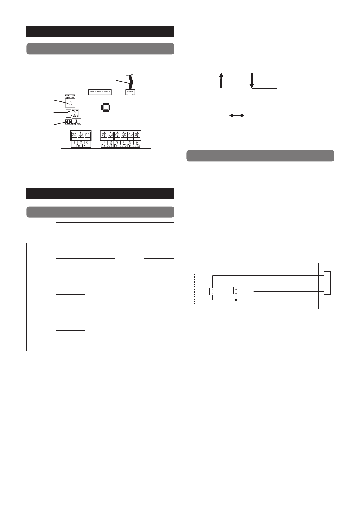
3.1. Connecting the PCB
■Input signal type
The input signal type can be selected.
Signal type (edge or pulse) can be switched by the DIP
switch 2 (SW2) on the External input and output PCB.
Description of External input/output PCB
To indoor unit PCB
Connector wire
Rotary switch
SW2
SW1
Fig. External input and output PCB
• Connection depends on the PCB type of the indoor unit.
Refer to the installation manual of the indoor unit for details
on how to connect to the indoor unit PCB.
4. SETTINGS
4.1. Connectable devices
External
input
External
output
External
input/
output
Operation/
Stop
Forced
thermostat
off
Operation
status
Error status
Indoor unit
fan
operation
status
External
heater
output
Terminal
block
Input 1/
Input 2
Input 1 Edge
Input
select
(SW1)
Dry
contact/
Apply
voltage
Output 1
Output 2
––
Output 3
Input
signal
(SW2)
Edge/Pulse
When SW2 is on the “Edge” side.
Edge
When SW2 is on the “Pulse” side.
The width of pulse must be longer than 200 msec.
Pulse
4.2. External input
• “Operation/Stop” mode or “Forced stop” mode can be
selected with function setting of indoor unit.
• A twisted pair cable (22AWG) should be used. Maximum
length of cable is 150 m.
• The wire connection should be separate from the power
cable line.
●
Input select
Use either one of these types of terminals according to
the application. (Both types of terminals cannot be used
simultaneously.)
• Dry contact
In case of internal power supply, set the slide switch of
SW1 to “NON VOL” side.
PCB
+
1 1
Input 1
Input 2
Connected unit
*1: The switches can be used on the following condition:
DC 12 V to 24 V, 1 mA to 15 mA.
+
-
1
2
C
En-2
 Loading...