

Page 1

SPARC JPS1
Implementation Supplement:
Fujitsu SPARC64 V
Fujitsu Limited
Release 1.0, 1 July 2002
Fujitsu Limited
4-1-1 Kamikodan ak a
Nahahara-ku, Kawasaki, 211-858 8
Japan
Part No. 806-6755-1.0
Page 2

Copyright 2002 Sun Microsystems, Inc., 901 San Antonio Road, Palo Alto, California 94303 U.S.A. All rights reserved.
Portions of this document are protected by copyright 1994 SP ARC International, Inc.
This product or document is protected by copyright and distributed under licenses restricting its use, copy ing, distribution, and decompilation. No part of this
product or document may be repr oduced in any form by any means without prior written authorization of Sun and its licensors, if any. Third-party software,
including font technology, is copyrighted and licensed from Sun suppliers.
Parts of the product may be derived fr om Berkeley BSD systems, l icensed from the U niversity of California. UNIX is a r egistered trademark in the U.S. and other
countries, exclusively licensed throug h X/Open Company, Ltd.
Sun, Sun Microsystems, the Su n logo, SunSoft, SunDocs, SunExpr ess, and Solaris are trad emarks, register ed trademarks, or service ma rks of Sun Micr osystems,
Inc. in the U.S. and other countries. All SPARC trademarks are used under license and are trademarks or registered trademarks of SPARC International, Inc. in the
U.S. and other countries. Products bearing SP ARC trademarks are based upon an ar chitecture developed by Sun Microsystems, Inc.
The OPEN LOOK a nd Sun™ Grap hical Use r Interfa ce was deve loped by Sun Micr osystems, Inc. fo r its users and lice nsees. Sun acknowledges the pioneering
efforts of Xerox in r esearching and developing the con cept of visual or graphical user interfaces for the computer ind ustry. Sun holds a non-exclusive license from
Xerox to the Xerox Graphical User Interface, w hich license also covers Sun’s licensees who implement OPEN LOOK GUIs and ot herwise comply with Sun’s
written license agreements.
RESTRICTED RIGHTS: Use, duplication, or disclosure by the U.S. Government is subject to restrictions of F AR 52.227-14(g)(2)(6/87) and F AR 52.227-19(6/87),
or DFAR 252.227-7015(b)(6/95) and DF AR 227.7202-3(a).
DOCUMENTATION IS PR OVIDED “AS IS” AND ALL EXPRESS O R IMPLIED CO NDITIONS, REPR ESENTATIONS A ND WARRANTIES, INCLUDING
ANY IMPLIED W ARRANTY OF MERCHANTABILITY , FITNESS FOR A PARTICULAR PURPOSE OR NON-INFRINGEMENT, ARE DISCLAIMED, EXCEPT
TO THE EXTENT THAT SUCH DISCLAIMERS ARE HELD TO BE LEGALLY INVALID.
Copyright 2002 Sun Microsystems, Inc., 901 San Antonio Road • Palo Alto, CA 94303-4900 Etats-Unis. Tous dro its réservés.
Ce produit ou document est protég é par un copyright et distribué avec des licences qui en r estreignen t l’utilisation, la copie, la distribution, et la décompilation.
Aucune partie de ce produit ou document ne peut être reproduite sous aucune forme, par quelque moyen que ce soit, sans l’autorisation préalable et écrite de Sun
et de ses bailleurs de licence, s’il y en a. Le logiciel détenu par des tiers , et qui comprend la technolo gie relative aux polices de caractèr es, est protég é par un
copyright et licencié par des fournisseurs de Sun.
Des parties de ce produit pourront êtr e dérivées des système s Berkeley BSD licenciés par l’Université de Califo rnie. UNIX est une mar que déposée aux Etats-Unis
et dans d’autres pays et licenciée exclusiveme nt par X/Open Company, Ltd. La notice suivante est applicable à Netscape Communicator™: Copyright 1995
Netscape Communications Corporation. T ous dr oits réservés.
Sun, Sun Microsys tems, the Sun logo, AnswerBook2, docs.s un.com, et Sol aris sont des ma rques de fabrique ou des ma rques dépo sées, ou marqu es de service, d e
Sun Microsystems, Inc. aux Etats-Unis et dans d’autres pays. Toutes les marques SPARC sont utilisées sous licence et sont des marques de fabrique ou des
marques déposées de SPARC International, Inc. aux Etats-Unis et dans d’autres pays. Les produits portant les marques SP ARC sont basés sur une ar chitecture
développée par Sun Microsystems, Inc.
L ’interface d’utilisation graphique OPEN LOOK et Sun™ a ét é développée par Sun Microsystems, Inc. pour ses utilisateurs et licenciés . Sun reconnaît les ef forts
de pionniers de Xerox pour la r echerche et le développem ent du concept des interfaces d’utilisatio n visuelle ou graphique pour l’industrie de l’informatique. Sun
détient une licence non exclusive de Xer ox sur l’interface d’utilisation graphique Xer ox, cette licence couvrant également les licen ciés de Sun qui mettent en place
l’interface d’utilisation graphique OPEN LOOK et qui en outre se conforment aux licences écrites de Sun.
CETTE PUBLICATION EST FOURNIE "EN L’ETAT" ET AUCUNE GARANTIE, EXPRESSE OU IMPLICITE, N’EST ACCORDEE, Y COMPRIS DES
GARANTIES CONCERNANT LA VALEUR MARCHANDE, L ’APTIT UDE DE LA PUBLICATION A REPONDRE A UNE UTILISA TION PARTICULIERE, OU
LE FAIT QU’ELLE NE SOIT PAS CONTREFAISANTE DE PRODUIT DE TIERS. CE DENI DE GARANTIE NE S’APPLIQUERAIT PAS, DANS LA MESURE
OU IL SERAIT TENU JURIDIQUEMENT NUL ET NON AVENU.
Copyright© 2002 Fujitsu Limited, 4-1-1 Kamikodanaka, Nakahara-ku, Kawasaki, 211-8588, Japan. All rights reserved.
This product and related documentation ar e protected by copyright and distributed unde r licenses restricting their use, copying, distribution, and decompilation.
No part of this product or related documentation may be r eproduced in any form by any means without prior w ritten authorization of Fujitsu Limited and its
licensors, if any.
Portions of this product may be derived fr om the UNIX and Berkeley 4.3 BSD Systems, licensed fr om UNIX System Laboratories, Inc., a wholly owned subsidiary
of Novell, Inc., and the University of California, respectively.
The product described in this book may be pro tected by one or more U.S . patents, foreign patents, or pending applications.
Fujitsu and the Fujitsu logo are trademarks of Fujitsu Limited.
This publication is provided “as is” without warranty of any kind , either express or implied, including, but not limited to, the implied warranties of
merchantability, fitness for a particular purpose, or noninfringement.
This publication could include technical inaccuracies or typographical err ors. changes are periodically add ed to the information herein; thes e changes will be
incorporated in new editions of the publication. Fujitsu limited may mak e improvements and/or changes in the pr oduct(s) and/or the program(s) described in
this publication at any time.
Sun Microsystems, Inc. Fujitsu Limited
901 San Antonio 4-1-1 Kamikodanaka
Palo Alto, California, 94303 Nakahara-ku, Kawasaki, 211-8588
U.S.A. Japan
http://www.sun.com http://www.fujitsu.com/
Release 1.0, 1 July 2002 F. Chapter 2
Page 3

3 SPARC JPS1 Implementation Supplement: Fujitsu SPARC64 V • Release 1.0, 1 July 2002
Page 4

F.CHAPTER
Contents
1. Ove r view 1
Navigating the SPARC64 V Implementation Supplement 1
Fonts and Notational Conventions 1
The SPARC64 V processor 2
Component Overview 4
Instruction Control Unit (IU) 6
Execution Unit (EU) 6
Storage Unit (SU) 7
Secondary Cache and External Access Unit (SXU) 8
2. Def i n itio n s 9
3. Architectu ra l Ove rv iew 13
4. Data Formats 15
5. Registers 17
Nonprivileged Registers 17
Floating-Point State Register (FSR) 18
Ti ck (TICK) Register 19
Privileged Registers 19
Trap State (TSTATE) Register 19
Ver sion (VER) Re g i s t e r 20
Ancillary State Registers (ASRs) 20
Registers Referenced Through ASIs 22
i
Page 5

Floating-Point Deferred-Trap Queue (FQ) 24
IU Deferred-Trap Queue 24
6. Instructions 25
Instruction Execution 25
Data Prefetch 25
Instruction Prefetch 26
Syncing Instructions 27
Instruction Formats and Fields 28
Instruct ion Categories 29
Control-Transfer Instructions (CT Is) 29
Floating-Point Operate (FPop ) Instructions 30
Implementation-Dependent Instructions 30
Processor Pipeline 31
Instruction Fetch Stages 31
Issue Stages 33
Execution Stages 33
Completion Stages 34
7. Traps 35
Processor States, Norma l and Spe cial Traps 35
RED_state 36
error_state 36
Trap Categories 37
Deferred Traps 37
Reset Traps 37
Uses of the Trap Categories 37
Trap Control 38
PIL Control 38
Trap-Table Entry Ad dresses 38
Trap Type (TT) 38
Details of Supported Traps 39
Trap Processing 39
Exception and Interrupt Descriptions 39
SPARC V9 Implementation-Dependent, Optional Traps That Are
Mandatory in SPARC JPS1 39
ii SPARC JPS1 Implementation Supplement: Fujitsu SPARC64 V • Release 1.0, 1 July 2002
Page 6

SPARC JPS1 Implementation-Dependent Traps 39
8. Memory Models 4 1
Overview 42
SPARC V 9 Mem o ry Mo de l 42
Mode Control 42
Synchronizing Instruction and Data Me mory 42
A. Instruction Definitions: SPARC64 V Extensions 45
Block Load and Store Instructions (VIS I) 47
Call and Link 49
Implementation-Dependent Instructions 49
Floating-Point Multiply-Add/Subtract 50
Jump and Link 53
Load Quadword, Atomic [Physical] 54
Memory Barrier 55
Partial Store (VIS I) 57
Prefetch Data 57
Read State Register 58
SHUTDOWN (VIS I) 58
Writ e Sta te Re gi s ter 59
Deprecated In st ruc t io n s 59
Store Barrier 59
B. IEEE Std 754 -198 5 R e qui rem e nts for SPARC V9 61
Traps Inhibiting Results 61
Floating-Point Nonstandard Mode 61
fp_exception_other Exception (ftt=unfinished_FPop) 62
Operation Under FSR.NS = 1 65
C. Implementation Dependencies 69
Definition of an Implementation Depe nde ncy 69
Hardware Characteristics 70
Implementation Dependency Categories 70
List of Implementation Dependencies 70
Release 1.0, 1 July 2002 F. Chapter Contents iii
Page 7

D. Form a l Spe c ific at io n of t he Mem ory Mod e ls 81
E. Op co de Map s 83
F. Memory Management Unit 85
Virtual Address Translation 85
Translation Table Entry (TTE) 86
TSB Organization 88
TSB Pointer Formation 88
Faults and Traps 89
Reset, Disable, and RED_state Behavior 91
Internal Regist ers an d A SI op era tion s 92
Accessing MMU Registers 92
I/D TLB Data In, Data Access, and Tag Read Regis ters 93
I/D TSB Extension Registers 97
I/D Synchronous Fault Status Registers (I-SF SR, D-SF SR ) 97
MMU Bypass 104
TLB Replacement Policy 105
G. Assembly Language Syntax 107
H. Software Considerations 109
I. Extending the SPARC V9 Architecture 111
J. Changes from SPARC V8 to SPARC V9 113
K. Programming with the Memory Models 115
L. Addr e ss Spa c e Iden ti fier s 117
SPARC64 V ASI Assignments 117
Special Memor y Acc e ss ASI s 119
Barrier Assist for Parallel Processing 121
Interface Definition 121
ASI Registers 122
M. Cache Orga n izatio n 125
Cache Types 125
Level-1 Instruction Cache (L1I Cache) 126
iv SPARC JPS1 Implementation Supplement: Fujitsu SPARC64 V • Release 1.0, 1 July 2002
Page 8

Level-1 Data Ca c he (L 1D C ach e) 12 7
Level-2 Unified Cache (L2 Cache) 127
Cache Coherency Protocols 128
Cache Control/Status Instructions 128
Flush Level-1 Instruction Cache (ASI_FLUSH _L1I) 129
Level-2 Cache Control Register (ASI_L2_CTRL) 130
L2 Diagnostics Tag Re ad (AS I_L 2_DI AG_ TAG_READ) 130
L2 Diagnostics Tag Re ad R egist ers ( AS I_L 2_DI AG_TAG_READ_REG) 131
N. Interrupt Handling 133
Interrupt D isp a tc h 13 3
Interrupt Re c ei ve 1 3 5
Interrupt Global Registers 136
Interrupt-Rela ted AS R Re gis ter s 136
Interrupt Vector Dispatch Register 136
Interrupt Vector Dispatch Status Register 136
Interrupt Vector Receive Register 136
O. Rese t, RED_ sta te, a nd err or_s t ate 13 7
Reset Types 137
Power-on Reset (POR) 137
Watchdog Reset (W DR) 138
Externally Initiated Reset (XIR) 138
Software-Initi ate d R eset (S IR) 13 8
RED_state and e rror_stat e 13 9
RED_state 140
error_state 140
CPU Fatal Error state 141
Processor State after Reset and in RED_state 141
Operating Status Register (OPSR) 146
Hard w are Po wer- O n Reset S e quence 1 4 7
Firmware Initialization Sequence 147
P. Error Handling 149
Error Classification 149
Fatal Error 149
Release 1.0, 1 July 2002 F. Chapter Contents v
Page 9

error_state Transition Error 150
Urgent Error 150
Restrainable Error 152
Action a n d E rror Cont ro l 153
Registers Related to Error Handling 153
Summary of Actions Upon Error Detection 154
Extent of Automatic Source Data Correction for Correctable Error 157
Error Marking for Cacheable Data Error 157
ASI_EIDR 161
Control o f E r ro r Actio n ( ASI_ERROR_CONTROL) 161
Fatal Error a n d erro r_state Transi t ion Error 1 63
ASI_STCHG_ERROR_INFO 163
Fatal Error Types 164
Types of error_state Transition Errors 164
Urgent Error 165
URGENT ERRO R STATUS (ASI_UGESR) 165
Action of
async_data_error
(ADE) Trap 168
Instruction End-Method at ADE Trap 170
Expected So ftw are Hand li ng of AD E Trap 171
Instruction Access Errors 173
Data Access Errors 173
Restrainable Errors 174
ASI_ASYNC_FAULT_STATUS (ASI_AFSR) 174
ASI_ASYNC_FAULT_ADDR_D1 177
ASI_ASYNC_FAULT_ADDR _U 2 178
Expected Software Handling of Restrainable Errors 179
Handling of Internal Register Errors 181
Register Error Handling (Excluding ASRs and ASI Registers) 181
ASR Error Handling 182
ASI Register Error Handling 183
Cache Error Handling 188
Handling of a Cache Tag Error 188
Handling of an I1 Cache Data Error 190
Handling of a D1 Cache Data Error 190
Handling of a U2 Cache Data Error 192
Automatic Way Reduction of I1 Cache, D1 Cache, and U2 Cache 193
vi SPARC JPS1 Implementation Supplement: Fujitsu SPARC64 V • Release 1.0, 1 July 2002
Page 10

TLB Error Handling 195
Handling of TLB Entry Errors 195
Automatic Way Reduction of sTLB 196
Handling of Extended UPA Bus Interface Error 197
Handling of Extended UPA Address Bus Error 197
Handling of Extended UPA Data Bus Erro r 197
Q. Perfo rman ce In strum e ntat io n 201
Performance Monitor Overview 201
Sample Pseudo co d es 2 01
Performance Monitor Description 203
Instruction Statistics 204
Trap-R el ate d St atisti cs 2 06
MMU Event Counters 207
Cache Event Counters 208
UPA Event Counters 210
Miscellaneous Counters 211
R. UPA Programmer’s Model 213
Mapping of the CPU’s UPA Port Slave Area 213
UPA PortI D Reg iste r 214
UPA Config Regi ster 215
S. Summary of Differences between SPARC64 V and UltraSPARC-III 219
Bibliography 223
General References 223
Index 225
Release 1.0, 1 July 2002 F. Chapter Contents vii
Page 11

viii SPARC JPS1 Implementation Supplement: Fujitsu SPARC64 V • Relea se 1. 0, 1 July 20 02
Page 12

F.CHAPTER
1
Overview
1.1 Navigating the SPARC64 V
Implementation Supplement
We sugges t that you approach this Imple mentation Supple ment SPARC Joint
Programming Specification as follows.
1. Familiarize yourself with the SPARC64 V processor and its components by
reading these sections:
■
The SPARC64 V processor on page 2
■
Component Overview on page 4
■
Processor Pipel ine on page 31
2. Study the terminology in Chapter 2, Definitions:
3. For details of a rchitectural changes, see the remaining chapters i n this
Implementation Supplement as your interests direct.
For this revision, we added new appendixes: Appendix R,
and Appendix S, Summary of Differences between SPARC64 V and UltraSPARC-III.
UPA Programmer’s Model
1.2 Fonts and Notational Conventions
Please refer to Section 1.2 of Commonality for font and notational conventions.
,
1
Page 13

1.3 The SPARC64 V processor
The SPARC64 V processor is a high-performance, high-reliability, and high-integrity
processor that fully implements the instruction set architecture that conforms to
SPARC V9, as described in JPS1 Commonality. In addition, the SPARC64 V processor
implements the following features:
64-bit virtual a ddress space and 4 3-bit physic al address space
■
Advanced RAS features that enable high-integrity error handling
■
Microarchitecture for High Performance
The SPARC64 V i s an out-of-order execution supersc alar processor that issues up to
four instructions per cycle. Instructions in the predicted path are issued in program
order and are stored temporarily in
of program order to appropriate execution units. Instructions commit in program
order when no exceptional conditions occur during execution and all prior
instructions commit (that is, the result of the instruction execution becomes visible).
Out-of-order execution in SPARC64 V contributes to high performance.
SPARC64 V implements a large branch history buffer to predict its instruction path.
The history buffer is large enough to sustain a good prediction rate for large-scale
programs such as DBMS and to support the advanced instruction fetch mechanism
of SPARC64 V. This instruction fetch scheme predicts the execution path beyond the
multiple conditional branches in accordance with the branch history. It then tries to
prefetch instructions on the predicted path as much as possible to reduce the effect
of the performance penalty caused by instruction cache misses.
reservation stations
until they are dispatched out
High Integration
SPARC64 V integrates an on-board, associative, level-2 cache. The level-2 cache is
unified for instruction and data. It is the lowest layer in the cache hierarchy.
This integration contributes to both performance and reliability of SPARC64 V. It
enables shorter access time and more associativity and thus contributes to higher
performance. It contributes to higher reliability by eliminating the external
connections for level-2 cache.
High Reliability and High Integri ty
SPARC64 V implements the following advanced RAS features for reliability and
integrity beyond that of ordinary microprocessors.
2 SPARC JPS1 Implementation Supplement: Fujitsu SPARC64 V • Release 1.0, 1 July 2002
Page 14

1. Advanced RAS features for caches
■
Strong cache error protection:
ECC protection for D1 (Data level 1) cache data, U2 (unified level 2) cache data,
■
and the U2 cache tag.
Parity protection for I1 (Instruction level 1) cache data.
■
Parity protection and duplication for the I1 cache tag and the D1 cache tag.
■
■
Automatic correction of all types of single-bit error:
Automatic single-bit error correction for the ECC protected data.
■
Invalidation and refilling of I1 cache data for the I1 cache data parity error.
■
Copying from duplicated tag for I1 cache tag and D1 cache tag parity errors.
■
■
Dynamic way reduction while cache consistency is maintained.
■
Error marking for cacheable data uncorrectable errors:
Special error-marking pattern for cacheable data with uncorrectable errors. The
■
identification of the module that first detects the error is embedded in the
special pattern.
Error-source isolation with faulty module identification in the special error-
■
marking. The identification information enables the processor to avoid
repetitive error logging for the same error cause.
2. Advanced RAS featur es for the core
■
Strong error protection:
Parity protection for all data paths.
■
Parity protection for most of software-visible regist ers and internal temporary
■
registers.
Parity predic tion or residue ch ecking for t he accumula tor outpu t.
■
■
Hardware instruction retry
■
Support for software instruction retry (after failure of hardware instruction retry)
■
Error isolation for software recovery:
Error indication for each programmable register group.
■
Indication of retryability of the trapped instruction.
■
Use of different error traps to differentiate degrees of adverse effects on the
■
CPU and the system.
3. Extended RAS inte rface to software
■
Error classification according to the severity of the effect on program execution:
Urgent error (nonmaskable): Unable to continue execution without OS
■
intervention; reported through a trap.
Restrainable error (maskable): OS controls whether the error is report ed
■
through a trap, so error does not directly affect program execution.
■
Isolated error indication to determine the effect on software
Release 1.0, 1 July 2002 F. Chapter 1 Overview 3
Page 15

■
Asynchronous data error (
Relaxed instruc tion en d metho d (precise , retryab le, not retryable ) for th e
■
async_data_error
exception to indicate how the instruction should end; depends
ADE
) trap for additional errors:
on the executing instruction and the detected error.
ADE
Some
■
Simultaneous reporting of all detected
■
traps that are deferred but retryable.
handling of retryability.
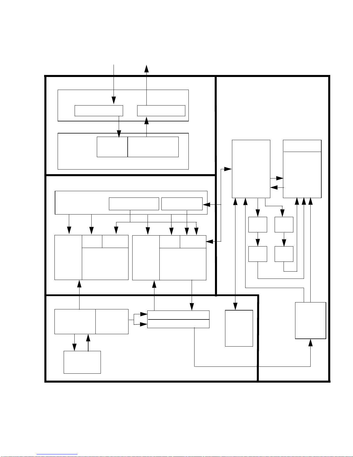
1.3.1 Component Overview
The SPARC64 V processor contains these components.
Instruction control Unit (IU)
■
Execution Unit (EU)
■
Storage Unit (SU)
■
Secondary cache and eXternal access Unit (SXU)
■
ADE
errors at the error barrier for correct
FIGURE 1-1
illustrates the major units; the following subsections describe them.
4 SPARC JPS1 Implementation Supplement: Fujitsu SPARC64 V • Release 1.0, 1 July 2002
Page 16
Extended UPA Bus
SX-Unit
UPA interface logic
MoveIn buffer
S-Unit interface
S-Unit
SX interface
I-TLB tag data
MoveOut buffer
U2$ U2$ data
tag 2M 4-way
SX order queue Store queue
D-TLB tag data
E-Unit
ALU
Input
Registers
and
Output
Registers
GUB FUB
ALUs
EXA
EXB
FLA
FLB
EAGA
EAGB
2048
+ 32
entry
Level-1 I cache
128 KB, 2-way
2048
+ 32
entry
Level-1 D cache
128 KB, 2-way
GPR FPR
I-Unit
Instruction Instruction
fetch buffer
pipeline
Commit stack entry
Reservation stations
PC
nPC
CCR
E-unit
control
logic
FSR
Branch
history
FIGURE 1-1
Release 1.0, 1 July 2002 F. Chapter 1 Overview 5
SPARC64 V Major Units
Page 17

1.3.2 Instruction Contro l Unit (IU)
The IU predicts the instruction execution path, fetches instructions on the predicted
path, distributes the fetched instructions to appropriate reservation stations, and
dispatches the instructions to the execution pipeline. The instructions are executed
out of order, and the IU commits the instructions in order. Major blocks are defined
TABLE 1-1
in
.
TABLE 1-1
Name Description
Instruction fetch pipeline Five stages: fetch address generation, iTLB access, iTLB match,
Branch history 16K entries, 4-way set associative.
Instruction buffer Six entries, 32 bytes/entry.
Reservation station Six reservation stations to h old instruct ions until th ey can
Commit stac k entries Sixty-four en tries; bas ically one ins truction/en try, to h old
PC, nPC, CCR , FSR Program-vi sible regi sters for instructio n execu tion con trol.
Instruction Control Unit Major Blocks
I-Cache fetch, and a write to I-buffer.
execute: RSBR for branch and the other control-transfer
instructions; RSA fo r load/st ore instruct ions; RSEA and RSEB for
integer arithmetic instructions; RSFA and RSFB for floating-point
arithmetic and VIS instruct ions.
information about instructions issued but not yet committed.
1.3.3 Execution Unit (EU)
The EU carries out execution of all integer arithmetic, logical, shift instructions, all
floating-point instructions, and all VIS graphic instructions.
EU major blocks.
TABLE 1-2
describes the
TABLE 1-2
Name Description
General register (gr) renaming
regi ste r fi le (GUB: gr update
buffer)
Gr a rch ite ctu re re gi ste r fi le ( GPR) 160 entries, 1 read port, 2 write ports
Floating-point (fr) renaming
regi ste r fi le (FUB: fr update
buffer)
Fr a rchi te ctu re re gis ter fi le ( FPR)Thirty-two entries,
EU control logic Controls the i nstruction e xecution s tages: instru ction
6 SPARC JPS1 Implementation Supplement: Fujitsu SPARC64 V • Release 1.0, 1 July 2002
Execution Un it Major B locks
Thirty-two entries, 8 read ports, 2 write ports
Thirty-two entries, 8 read ports, 2 write ports
6 read ports, 2 write ports
selection, register read, and execution.
Page 18

TABLE 1-2
Name Description
Execution Un it Major B locks (Continued)
Interface registers Input/output registers to other units.
Two i nteger execu tion pipeline s
(EXA, EXB)
Two floating-point and graphics
execution pipelines (FLA, FLB)
Two virtual address adders for
memory access pipeline (EAGA,
EAGB)
1.3.4 Storage Unit (SU)
The SU handles all sourcing and sinking of data fo r load and store instructions.
TABLE 1-3
describes the SU major blocks.
64-bit ALU and shifters.
Each floating-point execution pipeline can execute floating
point multipl y, floatin g point add/ sub, floatin g-point
multiply and add, floating point div/sqrt, and floatingpoint graph ics instruct ion.
Two 64-bit virtual addresses for load/store.
TABLE 1-3
Name Description
Storage Unit Major Blocks
Instruction level-1 cache 128-Kbyte, 2-way associative, 64-byte line; provides low latency
instruction source
Data level-1 cache 128-Kbyte, 2-way associative, 64-byte line, writeback; provides
the low latency data source for loads and stores.
Instruction Translation
Buffer
1024 entries, 2-way associative TLB for 8-Kbyte pages,
1024 entries, 2-way associative TLB for 4-Mbyte pages
1
,
32 entries, fully associative TLB for unlocked 64-Kbyte, 512-
1
Kbyte, 4-Mbyte
pages and locked pages in all sizes.
Data Translation Buffer 1024 entries, 2-way associative TLB for 8-Kbyte pages,
1024 entries, 2-way associative TLB for 4-Mbyte pages
1
,
32 entries, fully associative TLB for unlocked 64-Kbyte, 512-
1
Kbyte, 4-Mbyte
pages and locked pages in all sizes.
Store queue Decouples the pipeline from the latency of store operations.
Allows the pipeline to cont inue flowin g while the st ore waits for
data, and eventually writes into the data level 1 cache.
1. Unloced 4-Mbyte page entry is stored either in 2-way associative TLB or fully associative
TLB exclusively, depending on the setting.
Release 1.0, 1 July 2002 F. Chapter 1 Overview 7
Page 19

1.3.5 Secondary Cache and External Access Unit (SXU)
The SXU controls the operation of unified level-2 caches and the external data access
interface (extended UPA interface).
TABLE 1-4
describes the major block s of the SXU.
TABLE 1-4
Name Description
Unified level-2 ca che 2-Mbyte, 4-way associative, 64-byte line, writeback; provides low
Movein buffer Sixteen entries, 64-bytes/entry; catches returning data from
Moveout buffer Eight entries, 64-bytes/entry; holds writeback data. A maximum
Extended UPA interface
control logic
Secondary Cache and External Access Unit Major Blocks
latency data source for bo th instruction level-1 c ache and data
level-1 cache.
memory system in response to the cache line read request. A
maximum of 16 outstanding cache read operations can be issued.
of 8 outstanding writeback requests can be issued.
Send/receive transaction packets to/from Extended UPA
interface connected to the system.
8 SPARC JPS1 Implementation Supplement: Fujitsu SPARC64 V • Release 1.0, 1 July 2002
Page 20

F.CHAPTER
2
Definitions
This chapter defines concepts unique to the SPARC64 V, the Fujitsu implementation
of SPARC JPS1. For definition of terms that are common to all implementations,
please refer to Chapter 2 of Commonality.
committed Term applied to an instruction whe n it has co mpleted with out error and all
prior instructions have completed without error and have been committed. When
an instruction is committ ed, the state of the machin e is permanently chang ed
to reflect the result of the i nstruction; th e previously existi ng state i s no longe r
needed and can be disca rded.
completed Term applied to an instruction after it has finished, has sent a none rror status to
the issue unit, and all of its source operands are nonspeculative. Note:
Although the state of the machine has been temporarily altered by completion
of an instruction, th e state has no t yet been permane ntly changed and the old
state can be recovered until the instruction has been committed.
executed Term applied to an instruct ion that ha s been proces sed by an ex ecution un it
such as a load unit. An instruction is in execution as long as it is still being
processed by an execution unit.
fetched Term applied to an instruction that is obtained from the I2 instruction cache or
from the on-chip internal cache and sent to the issue unit.
finished Term applied to an instruction when it has completed execution in a functional
unit and has forwarded its result onto a result bus. Results on the result bus are
transferred to the register file, as are the waiting instructions in the instruction
queues.
initiated Term applied to an i nst ructi on wh en i t h as all of t he resources that it ne e ds ( for
example, source operands) and has been selected for execution.
instruction dispatch Synonym: instruction initiation.
instruction issued Term applied to an in struction when it has been d ispatched to a reservation
station.
9
Page 21

instruction retired Term applied to an instructi on when all machine resources (seri al numbers,
renamed registers) have been reclaimed and are available for use b y other
instructions. An instru ction can only be retired after it has been c ommitted.
instruction stall Term applied to an instructi on that is not allowed to be issued . Not every
instruction can be issued in a given cycle. The SPARC64 V implementation
imposes certain issue constrain ts based on resource availability and program
requirements.
issue-stalling
instruction An instruction that prevents ne w instructio ns from being is sued until it has
committed.
machine sync The state of a machine when all previously executing instructions have
committed; that is, when no issued but uncommitt ed instructions are in the
machine.
Memory Manag ement
Unit (MMU) Refers to the address translation h ardware in SPARC64 V that tr anslates 64-bit
virtual address into physica l address. T he MMU is c omposed of the mITLB,
mDTLB, uITLB, uDTLB, and the ASI registers used to manage address
translation.
mTLB Main TLB. Split i nto I and D, c alled mITL B and m DTLB, respectiv ely. Contai ns
address translations for the uITLB and uDT LB. When the uITL B or uDTLB do
not contain a transl ation, they ask the mTLB for th e translation. If the mTLB
contains the translatio n, it sends the translation to th e respective uTLB. If the
mTLB does not contain the translation , it generates a fast access excep tion to a
software translation trap handler, which will load the translation information
(TTE) into the mTLB and retry the access. See also TLB.
uDTLB Micro Data TLB. A small, fully associative buffer that contains address
translations for data accesses. Misses in the uDTLB are handled by the mTLB.
uITLB Micro Instruction TLB. A s mall, fully asso ciative buffer that co ntains address
translations fo r instructio n accesses . Misses i n the uTLB are handled by th e
mTLB.
nonspeculative A distribution syst em whereby a result i s guaranteed known correct or an
operand stat e is known to be vali d. SPAR C64 V employ s speculati ve
distribution, meaning that results can be distributed from functional units
before the point at which guaranteed validity of the result is known.
reclaimed The status when all instruction-related resources that were held until commit
have been released and are available for subse quent instructions. Ins truction
resources are usually reclaimed a few cycles after they are committed.
rename registers A large set of hardware registers implemented by SPARC64 V that are invisible
to the programmer. Before instructions are issued, source and destination
registers are mapped onto this s et of renam e register s. This al lows ins tructions
that normally would be blocked, waiting for an architected register, to proceed
10 SPARC JPS1 Implementation Supplement: Fujitsu SPARC64 V • Release 1.0, 1 July 2002
Page 22

in parallel . When i nstructi ons are committed, results in renamed registers are
posted to the architected registers in the proper sequence to produce the correct
program results.
scan A method used to initialize all of the machine state within a chip. In a chip that
has been desi gned t o be scann able, all of t he mac hine stat e is co nnected i n one
or several loops called “scan rings.” Initialization data can be scanne d into the
chip through the scan rings. The sta te of the machine also can be scanned out
through the scan rings.
reservation station A holding location that b uffers disp atch ed in structi on s unt il all i np ut o pera nds
are available. SPARC64 V implements dataflow execution based on operand
availability. When operands are available, the instruc tions in the reservation
station are scheduled for ex ecution. Reserv ation stations also con tain special
tag-matching logic that captures the appropriate operand data. Reservation
stations are sometimes referred to as queues (for example, the integer queue).
speculative A distribution syst em whereby a result is no t guaranteed as kn own to be
correct or an operan d state is not known to be valid. SPARC64 V employs
speculative distribution, meaning results can be distributed from functional
units before the point at which guaranteed validity of the result is known.
superscalar An implementation that allows several instructions to be issued, executed, and
committed in one clock cycle. SPARC64 V issues up to 4 instructions per clock
cycle.
sync Synonym: machine sync.
syncing instruction An instruction that causes a machine sync. Thus, before a syncing instruction is
issued, all previous instructions (in program order) must have been committed.
At that point, the syncing instruction is issued, executed, completed, and
committed by itself.
TLB Translation lo okaside buffer.
Release 1.0, 1 July 2002 F. Chapter 2 Definitions 11
Page 23

12 SPARC JPS1 Implementation Supplement: Fujitsu SPARC64 V • Release 1.0, 1 July 2002
Page 24

F.CHAPTER
3
Architectural Overview
Please refer to Chapter 3 in the Commonality section of SPARC Joint Programming
Specification.
13
Page 25

14 SPARC JPS1 Implementation Supplement: Fujitsu SPARC64 V • Release 1.0, 1 July 2002
Page 26

F.CHAPTER
4
Data Formats
Please refer to Chapter 4, Data Formats in Commonality.
15
Page 27

16 SPARC JPS1 Implementation Supplement: Fujitsu SPARC64 V • Release 1.0, 1 July 2002
Page 28

F.CHAPTER
5
Registers
The SPARC64 V processor includes two types of registers: general-purpose—that is,
working, data, control/status—and ASI registers.
The SPARC V9 architecture also defines two implementation-dependent registers:
the IU Deferred-Trap Queue and the Floating-Point Deferred-Trap Queue (FQ);
SPARC64 V does not need or contain either queue. All processor traps caused by
instructio n executi on are precise, and there are severa l disrupti ng traps caus ed by
asynchronous events, such as interrupts, asynchronous error conditions, and
RED_state entry traps.
For general information, please see parallel subsections of Chapter 5 in
Commonality. For easier referencing, this chapter follows the organization of
Chapter 5 in Commonality.
For information on MMU registers, please refer to Section F.10, Internal Registers a nd
ASI operations, on page 92.
The chapter contains these sections:
■
Nonprivileged Re gisters on page 17
■
Privileged Registers on page 19
5.1 Nonprivile ged Register s
Most of the definitions for the registers are as described in the corresponding
sections of Commonality. Only SPARC64 V-specific features are described in this
section.
17
Page 29

5.1.7 Floating-Point State Register (FSR)
Please refer to Section 5.1.7 of Commonality for the description of FSR.
The sections below describe SPARC64 V-specific features of the FSR regis ter.
FSR_nonstandard_fp (NS)
SPARC V9 defines the FSR.NS bit which, when set to 1, causes the FPU to produce
implementation-dependent results that may not conform to IEEE Std 754-1985.
SPARC64 V im plements thi s bit.
When FSR.NS = 1, denormal input operands and denormal results that would
otherwise trap are flushed to 0 of the same sign and an inexact exception is signalled
(that may be masked by FSR.TEM.NXM). See Section B.6, Floating-Point Nonstandard
Mode, on page 61 for details.
When FSR.NS = 0, the normal IEEE Std 754-1985 behavior is implemented.
FSR_version (
For each SPARC V9 IU implementation (as identified by its VER.impl field), there
may be one or more FPU implementations or none. This field identifies the
particular FPU implementation present. For the first SPARC64 V, FSR.ver =0 (impl.
dep. #19); however, future versions of the architecture may set FSR.ver to other
values. Consult the SPARC64 V Data Sheet for the setting of F SR.v er for your
chipset.
FSR_floating-point_trap_type (
The complete conditions under which SPARC64 V triggers
trap type
on page 61 (impl. dep. #248).
unfinished_FPop
)
ver
)
ftt
fp_exception_other
is described in Section B.6, Floating-Point Nonstandard Mode,
with
FSR_current_exception (cexc)
Bits 4 through 0 indicate that one or more IEEE_754 floating-point exceptions were
generated b y the most rece ntly execu ted FPop in struction. T he absence of an
exception causes the corresponding bit to be cleared.
In SPARC64 V , the cexc bits are set according to the following pseudocode:
if (<LDFSR or LDXFSR commits>)
<update using data from LDFSR or LDXFSR>;
else if (<FPop commits with ftt = 0>)
<update using value from FPU>
18 SPARC JPS1 Implementation Supplement: Fujitsu SPARC64 V • Release 1.0, 1 July 2002
Page 30

else if (<FPop commits with IEEE_754_exception>)
<set one bit in the CEXC field as supplied by FPU>;
else if (<FPop commits with unfinished_FPop error>)
<no change>;
else if (<FPop commits with unimplemented_FPop error>)
<no change>;
else
<no change>;
FSR Conformance
SPARC V9 a llows the TEM, cexc, and aexc fields to be implemented in hardware in
either of two ways (both of whi ch comply with IEEE Std 754-19 85). SPARC 64 V
follows case (1); that is, it implements al l three fields in conformance with IEEE Std
754-1985. See FSR Con formance in Section 5.1. 7 of Commonality for more
information about other implementation methods.
5.1.9 Tick (TICK) Register
SPARC64 V implements TICK.counter register as a 63-bit register (impl. dep.
#105).
Implementation Note –
when the TICK register is read is the value of TICK.counter when the RDTICK
instruction is executed. The difference between the counter values read from the
TICK register on two reads reflects the number of processor cycles executed between
the executi ons of the RDTICK instructions, not their commits. In longer code
sequences, the difference between this value and the value that would have been
obtained when the instructions are committed would have been small.
On SPARC64 V, the counter part of the value returned
5.2 Privileged Registers
Please refer to Section 5.2 of Commonality for the description of privileged registers.
5.2.6 Trap State (TSTATE) Register
SPARC64 V i mpleme nts only bits 2:0 of t he TSTATE.CWP field. Writes to bits 4 and 3
are ignored, and reads of these bits always return zeroes.
Release 1.0, 1 July 2002 F. Chapter 5 Registers 19
Page 31

Note –
Spurious s etting o f the PSTATE.RED bit by privileged software should not
be performed, since it will take the SPARC64 V into RED_state without the
required sequencing.
5.2.9 Version (VER) Register
TABLE 5-1
TABLE 5-1
Bits Field Value
63:48 manuf 000416 (impl. dep. #104)
47:32 impl 5 (impl. dep. #13)
31:24 mask n (The value of n depends on the processor chip version)
15:8 maxtl 5
4:0 maxwin 7
shows the values for the VER register for SPARC64 V.
VER
Register Encodings
The manuf field contains Fujitsu’s 8-bit JEDEC code in the lower 8 bits and zeroes in
the upper 8 bits. The manuf, impl, and mask fields are implemented so that they
may change i n future SPARC64 V processor versions. Th e mask field is incremented
by 1 any time a progra mmer-visible revision is made to the processor. See the
SPARC64 V Data Sheet to determine the current setting of the mask field.
5.2.11 Ancillary State Registers (ASRs)
Please refer to Section 5.2.11 of Commonality for details of the ASRs.
Performance Control Register (PCR) (ASR 16)
SPARC64 V implements the PCR register as described in SPARC JPS1 Commonality,
with additional features as describ ed in this section.
In SPARC64 V , the accessibilit y of PCR when PSTATE.PRIV = 0 is determined by
PCR.PRIV. If PSTATE.PRIV =0 and PCR.PRIV = 1, an attempt t o execute eit her
RDPCR or WRPCR will cause a
PCR.PRIV =0, RDPCR operates without privilege violation and WRPCR causes a
privileged_action
to) PCR.PRIV (impl. de p. #250).
See Appendix Q, Pe rformance Inst rumentatio n, for a detailed discussion of the PCR
and PIC register usage and event count definitions.
20 SPARC JPS1 Implementation Supplement: Fujitsu SPARC64 V • Release 1.0, 1 July 2002
exception only when an attempt is made to change (that is, write 1
privileged_action
exception. If PSTATE.PRIV =0 and
Page 32

The Performance Control Register in SPARC64 V is illustrated in
described in
TABLE 5-2
.
FIGURE 5-1
and
0
63 16 10
TABLE 5-2
Bit Field Description
OVF 0 SLSU0SC
4748
FIGURE 5-1
PCR
Bit Description
0
26273132
SPARC64 V Performance Control Register (PCR) (ASR 16)
0OVRO
25
NC
0
21
2224
20
1718
9
ULRO UT ST PRIV
40
12311
47:32 OVF Overflow Clear/Set/Status. Used to read counter overflow status (via RDPCR) and clear
or set counter overflow status bits (via WRPCR). PCR.OVF is a SPARC64 V-specif ic field
(impl. dep. #207).
The following figure depicts the bit layout of SPARC64 V OVF field for four counter
pairs. Counter status bits are cleared on write of 0 to the appropriate OVF bit.
L2U2L3U3
15
L0U0L1U10
01234567
26 OVRO Overflow read-only. Write-only/read-as-zero field specifying PCR.OVF update behavior
for WR PCR. P CR. The OVR O field is implementation -dependent (impl. dep. #207).
WRPCR.PCR with PCR.OVRO = 1 inhibits updating of PCR.OVF for the current write
only. Th e intention o f PCR.OVRO is to w rite PCR while preserving current PCR.OVF
value. PCR.OVF is main tained int ernally by hardware, so a s ubsequent RDPCR.PCR
returns accurate overflow status at the time.
24:22 NC Number o f counter p airs. Th ree-bit, read -only fiel d specify ing the n umber of counte r
pairs, encoded as 0–7 for 1–8 counter pairs (impl. dep. #207).
For SPARC64 V, the hardcoded value of NC is 3 (indicating presence of 4 counter pai rs).
20:18 SC Select PIC. In SPARC64 V, three-bit fie ld specify ing which c ounter pa ir is currently
selected as PIC (ASR 17) and which SU/SL values are visible to software. On write,
PCR.SC selects wh ich counter pair is upda ted (unless PCR.ULRO is set; see below). On
read, PCR.SC selects which counter pair is to be read through PIC (ASR 17).
16:11 SU Defined (as S1) in SPARC JPS1 Commonality.
9:4 SL Defined (as S0) in SPARC JPS1 Commonality.
3 ULRO Implementation-dependent field (impl. dep. #207) that specifies whether SU/SL are
read-only. In SPARC64 V, this field is write-only/read-as-zero, specifying update
behavior of SU/SL on write. When PCR.ULRO = 1, SU/SL are considered as read-only;
the values set on PCR .SU/P CR.SL are not written into SU/SL. When PC R.ULR O = 0,
SU/SL are updated. PCR.ULRO is intended to switch visible PIC by writing PCR.SC,
without affecting current selection of SU/SL of that PIC. On PCR read, PCR.SU/PCR.SL
always shows the current setting of the PIC regardless of PCR.ULRO.
2 UT Defined in SPARC JPS1 Commonality.
1 ST Defined in SPARC JPS1 Commonality.
Release 1.0, 1 July 2002 F. Chapter 5 Registers 21
Page 33

TABLE 5-2
Bit Field Description
0 PRIV Defi ned in SPARC JPS1 Commonality, with the additional function of controlling PCR
PCR
Bit Description (Continued)
accessibility as describ ed above (impl. d ep. #250).
Performance Instrumentation Counter (PIC) Register (ASR
17)
The PIC register is implemented as described in SPARC JPS1 Commonality.
Four PICs are implemented in SPARC64 V. Each is accessed through ASR 17, using
PCR.SC as a select field . Read/write acc ess to the PIC will access the PICU/PICL
counter pair selected by PCR. For PICU/PICL enco dings of spec ific even t counter s,
see
Appendix Q, Performance Instrumentation
.
Counter Overflow.
and an interrupt level-15 exception is generated. The counter overflow trap is
triggered on th e tra nsition from value FFFF FFFF
are generated simultaneously, then multiple overflow status bits will be set. If
overflow status bits are already set, then they remain set on counter overflow.
Overflow status bits are cleared by software writing 0 to the appropriate bit of
PCR.OVF and may be set by writing 1 to the appropriate bit. Setting these bits by
software does not generate a level 15 i nterrupt.
On overflow, counters wrap to 0, SOFTINT register bit 15 is set ,
to value 0. If multiple overflows
16
Dispatch Control Register (DCR) (ASR 18)
The DCR is not implemented in SPARC64 V. Zero is returned on read, and writes to
the register are ignored. The DCR is a privileged register; attempted access by
nonprivileged (user) code generates a
privileged_opcode
exception.
5.2.12 Registers Referenced Thro ugh ASIs
Data Cache Unit Control Register (DCUCR)
ASI 4516 (ASI_DCU_CONTROL_REGISTER), VA = 016.
The Data Cache Unit Control Register contains fields that control several memory-
related hardware functions. The functions include Instruction, Prefetch, write and
data caches, MMUs, and watchpoint setting. SPARC64 V implements most of
DCUCUR’s functions described in Section 5.2.12 of Commonality.
22 SPARC JPS1 Implementation Supplement: Fujitsu SPARC64 V • Release 1.0, 1 July 2002
Page 34

Aft er a p o wer- on re se t ( POR), all fields of DCUCR, including implementationdependent fields, are set to 0. After a WDR, XIR, o r SIR reset, all fields of DCUCR,
including implement ation-d ependen t fields, are se t to 0.
The Data Cache Unit Control Register is illustrated in
TABLE 5-3
—
5063
TABLE 5-3
Bits Field Type Use — Description
0
0
Implementation dependent PM VM PR PW VR DM 0
4849
FIGURE 5-2
DCUCR Description
. In the table, bits are grouped by function rather than by strict bit sequence.
WEAK_SPCA
41
DCU Control Register Access Data Format (ASI 4516)
2425323347
FIGURE 5-2
VW
and described in
—
IM 0
012342122234042 20
49:48 CP, CV RW Not implemented in SPARC64 V (impl. dep. #232). It reads as 0 and writes to
it are ignored.
47:42 impl. dep. Not used. It reads as 0 and writes to it are ignored.
41 WEAK_SPCA RW Used for disabling speculative memory access (impl. dep. #240). When
DCUCR.WEAK_SPCA = 1, the branch history table is cleared and no longer
issues aggressive instruction prefetch.
During DCU CR.WE AK_SP CA = 1, agg ressive instru ction prefetchi ng is
disabled and any load and store instructions are considered presync
instructions tha t are executed when all previo us instructio ns are commit ted.
Because all CTI are considered as not taken, instructions residing beyond 1
Kbyte of a CTI may be fetched and executed.
On entering aggressive instruction Prefetch disable mode, supervisor
software should issue membar #Sync, to make sure all in-flight instructions
in the pipeline are discarded.
During DCU CR.WE AK_SP CA = 1, an L2 cache flush by wr iting 1 to
ASI_L2_CTRL.U2_FLUSH remains pending internally until
DCUCR.WEAK_SPCA is set to 0. To wait for completion of the cache flush, a
member #Sync must be issued after DCUCR.WEAK_SPCA is set to 0.
Executing a membar #Sync while the DCUCR.WEAK_SPCA = 1 after writing 1
to ASI_L2_CTRL. U2_FL USH d oes no t wait for t he cache flush to complete .
40:33 PM<7:0> Defined in SPARC JPS1 Commonality.
32:25 VM<7:0> Defined in SPARC JPS1 Commonality.
24, 23 PR, PW Defined in SPARC JPS1 Commonality.
22, 21 VR, VW Defined in SPARC JPS1 Commonality.
20:4 — Reserved.
3 DM Defined in SPARC JPS1 Commonality.
2 IM Defined in SPARC JPS1 Commonality.
Release 1.0, 1 July 2002 F. Chapter 5 Registers 23
Page 35

TABLE 5-3
Bits Field Type Use — Description
1 DC RW Not implemented in SPARC64 V (impl. dep. #252). It reads as 0 and writes to
0 IC RW Not implemented in SPARC64 V (impl. dep. #253). It reads as 0 and writes to
DCUCR Description (Continued)
it are ignored.
it are ignored.
Data Watchpoint Registers
No impleme ntation-dep endent feat ure of SPARC 64 V reduces the reliab ility of data
watchpoints (imp l. dep. #244).
SPARC64 V employs conservative check of PA/VA watchpoint over partial store
instruction. See Section A.42, Partial Store (VIS I), on page 57 for details.
Instruction Trap Regist er
SPARC64 V impl ements the Instruct ion Trap Regi ster (impl. dep. #205).
In SPARC64 V, the least significant 11 bits (bits 10:0) of a CALL or branch (BPcc,
FBPfcc, Bicc, BPr) instruction in an instruction cache are identical to their
architectural encoding (as it ap pears in main memory) (impl. dep. #245).
5.2.13 Floating-Point Deferred-Trap Queue (FQ)
SPARC64 V does not contain a Floating-Point Deferred-trap Queue (impl. dep. #24).
An attempt to read FQ with an RDPR instruction generates an
exception (impl . dep. #25).
illegal_instruction
5.2.14 IU Deferred-Trap Queue
SPARC64 V neither has nor needs an IU deferred-trap queue (impl. dep. #16)
24 SPARC JPS1 Implementation Supplement: Fujitsu SPARC64 V • Release 1.0, 1 July 2002
Page 36

F.CHAPTER
6
Instructions
This chapter presents SPARC64 V implementation-specific instruction details and the
processor pipeline information in these subsections:
■
Instruction Execution on page 25
■
Instruct ion Format s and Field s on page 28
■
Instruction Categories on page 29
■
Processor Pipel ine on page 31
For additional, general information, please see parallel subsections of Chapter 6 in
Commonality. For e asy referencing, we follow the organization of Chapter 6 in
Commonality.
6.1 Instruction Execution
SPARC64 V is an advanced superscal ar implementation of SPARC V9. Several
instructions may be issued and executed in parallel. Although SPARC64 V provides
serial program executio n seman tics, some of the impleme ntation c haracter istics
described below are part of the architecture visible to software for correctness and
efficiency. The affected software includes optimizing compilers and supervisor code.
6.1.1 Data Prefetch
SPARC64 V employs speculative (out of program order) execution of instructions; in
most cases, the effect of these instructions can be undone if the speculation proves to
be incorrect .
prefetching. Formally, SPARC64 V employs the following rules regarding speculative
prefetching:
1. An async_data_error may be signalled during speculative data prefetching.
1
However, exceptions can occur because of speculative data
25
Page 37

1. If a memory operation y resolves to a volatile memory address (location[y]),
SPARC64 V will not speculatively prefetch location[y] for any reason; location[y]
will be fetched or stored to only when operation y is commitable.
2. If a mem ory operation y resolves to a nonvolatile memory address (location[y]),
SPARC64 V may speculatively prefetch location[y] subject, adhering to the
following subrules:
a. If an operatio n y can be speculatively prefetched according to the prior rule,
operations with store semantics are speculatively prefetched for ownership
only if they are prefetched to cacheable locations. Operations without store
semantics are speculatively prefetched even if they are noncacheable as long as
they are not volatile.
b. Atomic operations (CAS(X)A, LDSTUB, SWAP) are never speculatively
prefetched.
SPARC64 V provides two mechanisms to avoid speculative execution of a load:
1. Av oid speculation by disall o wing speculative accesses to certain memory pa ge s or
I/O spaces.
This can be done by setting the E (side-effect) bit in the PTE for all
memory pages that should not allow speculation. All accesses made to memory
pages that have the E bit set in their PTE will be delayed until they are no longer
speculativ e or unt il th ey are can cell ed
.
See Appendix F, Memory Manage ment Uni t,
for details.
2. Alt ernate space load instructions tha t force program order, such as
ASI_PHYS_BYPASS_WITH_EBIT[_L] (AS I = 15
executed.
6.1.2 Instruction Prefetch
The processor prefetches instructions to minimize cases where the processor must
wait for instruction fetch. In combination with branch prediction, prefetching may
cause the processor to access instructions that are not subsequently executed. In
some cases, the specula tive instruction accesse s will reference data pages.
SPARC64 V does not generate a trap for any exception that is caused by an
instruction fetch until all of the instructions before it (in program order) have been
committed.
1. Hardware errors and other asynchronous errors may generate a trap even if the instruction that caused the
trap is never committed.
1
, 1D16), will not be speculatively
16
26
SPARC JPS1 Implementation Supplement:
Fujitsu SPARC64 V
• Release 1.0, 1 July 2002
Page 38

6.1.3 Syncing Instructions
SPARC64 V has instructions, called syncing instructions, that stop execution for the
number of cycles it takes to clear the pipeline and to synchronize the processor.
There are two types of synchronization, pre and post. A presyncing instruction waits
for all previous instructions to commit, commits by itself, and then issues successive
instructions. A postsyncing instruction issues by itself and prevents the successive
instructions from issuing until it is committed. Some instructions have both pre- and
postsync attributes.
In SPARC64 V almost all instructions commit in order, but store instruction commit
before becoming globally visible. A few syncing instructions cause the processor to
discard prefetched instruction s and to refetch the successiv e instructions.
lists all pre-/postsync instructions and the effects of instruction execution.
TABLE 6-1
TABLE 6-1
Opcode
ALIGNADDRESS{_LITTLE} Yes
BMASK Yes
DONE Yes Yes
FCMP(GT,LE,NE,EQ)(16,32)Yes
FLUSH Yes Yes Yes
FMOV(s,d)icc Yes
FMOVr Yes
LDD Yes Yes
LDDA Yes Yes
LDDFA Yes
memory access with
ASI=ASI_PHYS_BYPASS_E C{_LI TTLE} ,
ASI_PHYS_BYPASS_EC_WI TH_E_ BIT{_ LITTL E}
LDFSR, LDXF SR Yes
MEMBAR Yes Yes
MOVfcc Yes
MULScc Yes
PDIST Yes
RDASR Yes
RETRY Yes Yes
SIAM Yes
STBAR Yes
STD Yes
SPARC64 V Syncing Instructions
Sync?
Yes
Presyncing Postsyncing
Wai t f or
store global
visibility?
1
Sync?
Yes
Discard
prefetched
instructions?
Release 1.0, 1 July 2002 F. Chapter 6 Instructions 27
Page 39

TABLE 6-1
Opcode
SPARC64 V Syncing Instructions (Continued)
Sync?
Presyncing Postsyncing
Wai t f or
store global
visibility?
Sync?
STDA Yes
STDFA Yes
STFSR, STXF SR Yes
Tcc Yes Yes Yes
WRASR Yes
cmask !=0
1. When
WRGSR
2.
#
only.
.
2
Yes
6.2 Instruction Formats and Fields
Instructions are encoded in five ma jor 32-bit formats and several mi nor formats.
Please refer to Section 6.2 of Commonality for illustrations of four major formats.
FIGURE 6-1
illustrates Format 5, unique to SPARC64 V.
Discard
prefetched
instructions?
Format 5 (op = 2, op3 = 3716): FMADD, FMSUB, FNMADD, and FNMSUB (in p lace of IMPDEP2B)
op3rdop rs1 rs3 rs2var
31 141924 18 13 12 5 4 02530 29 11 10 9 7 617 8
FIGURE 6-1
Summary of Instruction Formats: Format 5
Instruction fields are those shown in Section 6.2 of Commonality. Three additional
fields are implemented in SPARC64 V. They are described in
TABLE 6-2
Bits Field Description
Instruction Fields Specific to
13:9 rs3 This 5-bit field is the address of the third f register source operand for
the floating-poi nt multiply- add and mu ltiply-subtrac t instruction.
8.7 var This 2-bit field specifies w hich spe cific opera tion (vari ation) to pe rform
for the floating-po int multiply -add and multi ply-subtract ins tructions
6.5 size This 2-bit field specifies the size of the operands for the floating-point
multiply-add a nd multip ly-subtract in structions.
SPARC64 V
size
TABLE 6-2
.
28 SPARC JPS1 Implementation Supplement: Fujitsu SPARC64 V • Release 1.0, 1 July 2002
Page 40

size
Since
= 00 is not
IMPDEP2B
and since
size
is not implemented in SPARC64 V, the instruction with
illegal_instruction
exception in SPARC64 V.
6.3 Instruction Categories
SPARC V9 instructions comprise the categories listed below. All categories are
described in Section 6.3 of Commonality. Subsections in bold face are SPARC64 V
implementation dependencies.
■
Memory access
■
Memory synchronization
■
Integer arithmetic
■
Control transfer (CTI)
■
Conditional moves
■
Register window management
■
State register access
■
Privileg ed register access
■
Floating-point operate (FPop)
■
Implementation-dependent
= 11 assumed quad operations but
= 00 or 11 generates an
size
6.3.3 Control-Transfer Instructions (CTIs)
These are the basic control-transfer instruction types:
■
Conditional branch (Bicc, BPcc, BPr, FBfcc, FBPfcc)
■
Unconditional branch
■
Call and link (CALL)
■
Jump and link (JMPL, RETURN)
■
Return from trap (DONE, RETRY)
■
Tr ap (Tcc)
Instructions other than CALL and JMPL are described in their entirety in Section 6.3.2
of Commonality. SPARC64 V implements CALL and JMPL as described below.
CALL and JMPL Instructions
SPARC64V writes all 64 bits of the PC into the destination register when
PSTATE.AM = 0. The upper 32 bits of r[15] (CALL) or of r[rd] (JMPL) are written
as zeroes when PSTATE.AM = 1 (impl. dep. #125).
Release 1.0, 1 July 2002 F. Chapter 6 Instructions 29
Page 41

SPARC64 V implements JMPL and CALL return prediction hardware in a form of
special stack, called the Return Address Stack (RAS). Whenever a CALL or JMPL that
writes to %o7 (r[15]) occurs, SPARC64 V “push e s” the return address (PC+8) onto
the RAS. When either of the synthet ic instr uctions retl (JMPL [%o7+8]) and ret (JMPL
[%i7+8]) are subsequently executed, the return address is predicted to be the
address stored on the top o f the RAS and the RAS is “popped.” If the prediction in
the RAS is incorrect, SPARC64 V backs up and starts issuing instructions from the
correct target address. This backup takes a few extra cycles.
Programming Note –
take into account how the RAS works. For example, tricks that do nonstandard
returns in hopes of boosting performance may require more cycles if they cause the
wrong RAS value to be used for predicting the address of the return. Heavily nested
calls can also cause earlier entries in the RAS to be overwritten by newer entries,
since the RAS only has a limited number of entries. Eventually, some return
addresses will be mispredicted because of the overflow of the RAS.
For maximum performance, software and compilers must
6.3.7 Floating-Point Operate (FPop) Instructions
The complete conditions of generating an
FSR.ftt =
Mode on page 61.
The SPARC64 V-specific FMADD and FMSUB instructions (described below) are also
floating-point operations. They require the floating-point unit to be enabled;
otherwise, an
instructions. However, these instructions are not included in the FPop category and,
hence, reserved encodings in these opcodes generate an
defined in Section 6.3.9 of Commonality.
unfinished_FPop
fp_disabled
trap is generated. They also affect the FSR, like FPop
are described in Section B. 6, Floating-Point Nonstandard
fp_exception_other
illegal_instru ction
except ion with
exception, as
6.3.8 Implementation-Dependent Instructions
SPARC64 V uses the IMPDEP2 instruction to implement the Floating-Point MultiplyAdd/Subtract and Negative Multiply-Add/Subtract instructions; these have an op3
field = 37
definitions of these instructions. Opcode space is reserved in IMPDEP2 for the quad-
precision forms of these instructions. However, SPARC64 V does not currently
implement the quad-precision forms, and the processor generates an
exception if a quad-precision form is specified. Since these instructions are not part
of the required SPARC V9 architecture, the operating system does not supply
software emulat ion routine s for the quad versions of these instru ctions.
SPARC64 V uses the IMPDEP1 instruction to implement the graphics acceleration
instructions.
30 SPARC JPS1 Implementation Supplement: Fujitsu SPARC64 V • Release 1.0, 1 July 2002
(IMPDEP2). See Floating-Point Multiply-Add/Subtract on page 50 for fuller
16
illegal_instruction
Page 42

6.4 Processor Pipeline
The pipeline of SPARC64 V consists of fifteen stages, shown in FIGURE 6-2. Each
stage is referenced by one or two letters as follows:
IA IT IM IB IR
EDPBX UW
6.4.1 Instruction Fetch Stages
■
IA (Instruction Address generation) — Calculate fetch target address.
■
IT (Instruction TLB Tag access) — Instruction TLB tag search. Search of BRHIS
and RAS is also started.
■
IM (Instruction TLB tag Match) — Check TLB tag is matched.
The result of BRHIS and RAS search is also avai lable at this stage and is
forwarded to IA stage for subsequent fetch.
■
IB (Instruction cache Buffer read) — Read L1 cache data if TLB is hit.
■
IR (Instruction read Result) — Write to I -Buffer.
Ps Ts Ms Bs Rs
IA through IR stages are dedicated to instruction fetch. These stages work in concert
with the cache access unit to supply instructions to subsequent stages. The
instructions fetched from memory or cache are stored in the Instruction Buffer (Ibuffer). The I-buffer has six entries, each of which can hold 32-byte-aligned 32-byte
data (eight instructions).
SPARC64 V ha s a branch prediction mechanism an d resources named BRHIS
(BRanch HIStory) and RAS (Return Address Stack). Instruction fetch stages use these
resources to determine fetc h addresses.
Instruction fetch stages are designed so that they work independently of subsequent
stages as much as possible. And they can fetch instructions even when execution
stages stall. These stages fetch until the I-Buffer is full; further fetches are possible by
requesting prefetches to the L1 cache.
Release 1.0, 1 July 2002 F. Chapter 6 Instructions 31
Page 43
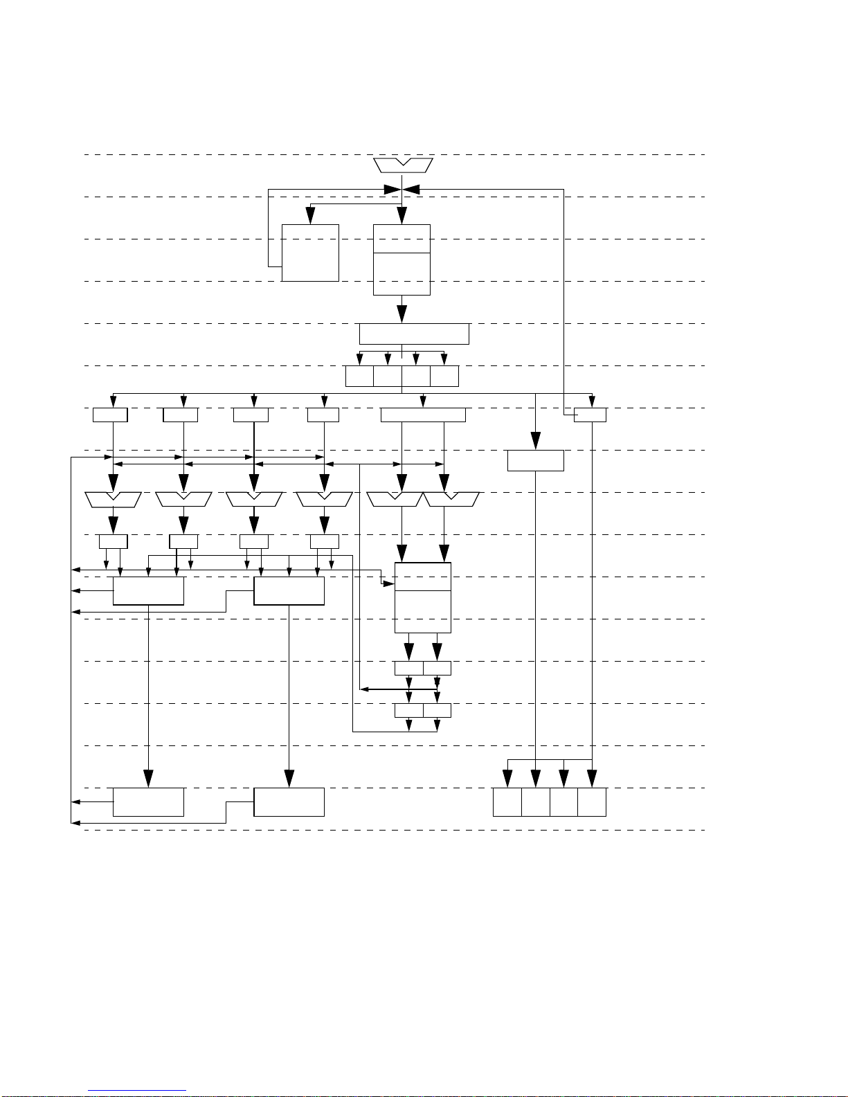
BRHIS
IF EAG
iTLB
L1I
Instruction Buffer
IWR
IA
IT
IM
IB
IR
E
D
RSFA
FXB EXBFXA EXA EAGA EAGB
RSFB RSEBRSEA
FUB
RRRRRR
RR
GUB
RSA
dTLB
L1D
LB
LR
FPR
GPR
CSE
ccr fsr
RSBR
PCnPC
Ps
Ts
Ms
Bs
Rs
P
B
X
U
W
FIGURE 6-2
32 SPARC JPS1 Implementation Supplement: Fujitsu SPARC64 V • Release 1.0, 1 July 2002
SPARC64 V Pipeline
Page 44

6.4.2 Issue Stages
■
E (Entry) — Instructions a re passed from fe tch stages .
■
D (Decode) — Assign resources and dispatch t o reservation station (RS.)
SPARC64 V is an out-of-order execution CPU. It has six execution units (two of
arithmetic and logic unit, two of floating-point unit, two of load/store unit). Each
unit except the load/store unit has its own reservation station. E and D stages are
issue stages tha t decod e in structi ons an d dis patch them to th e target RS. SPARC64 V
can issue up to four instructions per cycle.
The resources needed to execute an instruction are assigned in the issue stages. The
resources to be allocated include the following:
■
Commit stack entry (CSE)
■
Renaming registers of integer (GUB) and floating-point (FUB)
■
Entries of reservations stations
■
Memory access ports
Resources needed for an instruction are specific to the instruction, but all resources
must be assigned at these stages. In normal execution, assigned resources are
released at the very last stage of the pipeline, W-stage.
stage and W-stage are considered to be in-flight. When an exception is signalled, all
in-flight instructions and the resources used by them are released immediately. This
behavior enables the decoder to restart issuing instructions as quickly as possible.
1
Instructi ons betw een the E-
The number of in-flight instructions depends on how many resources are needed by
them. The maxi mum number is 64.
6.4.3 Execution Stages
■
P (priority ) — Select an instruction from those that have met the conditions for
execution.
■
B (buffer read) — Read register file, or receive forwarded data from another
pipelines.
■
X (execute) — Execution.
Instructions in reservation stations will be executed when certain conditions are met,
for example, the values of source registers are known, the execution unit is available.
Execution latency varies from one to many, depending on the instruction.
1. An entry in a reservation statio n is rel eased at the X-s tage.
Release 1.0, 1 July 2002 F. Chapter 6 Instructions 33
Page 45

Execution Stages for Cache Access
Memory access requests are passed to the cache access pipeline after the target
address is calculated. Cac he access stages work t he same way as instruction fetch
stages, exce pt for the han dling of bra nch prediction . See Section 6.4.1, Instruction
Fetch Stages, for details. Stages in instruction fetch and cache access correspond as
follows:
Instruction Fetch Stages Cache Access
IA Ps
IT Ts
IM Ms
IB B s
IR Rs
When an exception is si gnalled, fetch ports and store ports use d by memory access
instructions are released. The cache access pipeline itself remains working in order to
complete o utgoing m emory acce sses. When data is retur ned, it is th en stored to the
cache.
6.4.4 Completion Stages
■
U (Update) — Update of physical (renamed) register.
■
W (Write) — Update of architectural regis ters and retire; excep tion handlin g.
■
After an out-of-order execution, execution reverts to program order to complete.
Exception handling is done in the completion stages. Exceptions occurring in
execution stag es are not handled imme diately but are signal led when the
instruction is completed.
1
1. RAS-related except ion ma y be s igna lled b efor e co mpletio n.
34 SPARC JPS1 Implementation Supplement: Fujitsu SPARC64 V • Release 1.0, 1 July 2002
Page 46

F.CHAPTER
7
Traps
Please refer to Chapter 7 of Commonality. Section numbers in this chapter
correspond to those in Chapter 7 of Commonality.
This chapter adds SPARC64 V-specific information in the following sections:
■
Processor States, Normal and Special Traps on page 35
■
RED_state on page 36
■
error_state on page 36
■
Trap Cate g o r ies on page 37
■
Deferred Traps on page 37
■
Reset Traps on page 37
■
Uses of the Trap Categories on page 37
■
Trap Cont rol on page 38
■
PIL Control on page 38
■
Trap-Table Entry Addresses on page 38
■
Trap Type (TT) on page 3 8
■
Details of Supported Traps on page 39
■
Exception and Interrupt Descriptions on page 39
7.1 Processor States, Normal and Special
Traps
Please refer to Section 7.1 of Commonality.
35
Page 47

7.1.1 RED_state
R ED_ s ta t e Tr a p Ta ble
The RED_state trap vector is located at an implementation-dependent address
refe rre d t o as RSTVaddr. The value of RSTVaddr is a constant within each
implementation; in SPARC64 V this virtual address is FFFF FFFF F000 0000
which translates to physical address 0000 07FF F000 0000
dep. #114).
RED_state Execution Environment
In RED_state, the processor is forced to execute in a restricted environment by
overriding the values of some processor controls and state registers.
,
16
in RED_state (impl.
16
Note –
SPARC6 4 V has the fo llowing imp lementat ion-depen dent behav ior in RED_stat e
(impl. dep. #115):
■
■
■
Note –
should attempt to recove r from potentially catastroph ic error conditions or to disable
the failing componen ts. When RED_sta te i s entered after a reset, the software
should create the environment necessary to restore the system to a running state.
The values are overridden, not set, allowing them to be switched atomically.
While in RED_state, all i nternal ITLB- based translat ion function s are disabled .
DTLB-based translations are disabled upon entry but may be reenabled by
software while in RED_state. However, ASI-based access functions to the TLBs
are still available.
While mTLBs and uTLBs are disabled, all accesses are assumed to be
noncacheable and strongly ordered for data access.
XIR errors are not masked and can cause a trap.
When RED_sta te is entered because of component failures, the handler
7.1.2 error_state
The processor enter s error_state when a trap occurs while the processor is
already at its maximum supported trap l evel (that i s, when TL = MAXTL) (impl. dep.
#39).
36 SPARC JPS1 Implementation Supplement: Fujitsu SPARC64 V • Release 1.0, 1 July 2002
Page 48

Although the standard behavior of the CPU upon an entry into error_state is to
internally generate a
entry to error_state depending on a setting in the OPSR register (impl. dep #40,
#254).
watchdog_reset
7.2 Trap Categories
Please refer to Section 7.2 of Commonality.
An exception or interrupt request can cause any of the following trap types:
■
Precise trap
■
Deferred trap
■
Disrupting trap
■
Reset trap
7.2.2 Deferred Traps
Please refer to Section 7.2.2 of Commonality.
(WDR), the CPU optionally stays halted upon an
SPARC64 V implements a deferred trap to signal certain error conditions (impl. dep.
I_UGE
#32). Please refer to the description of
the instruction that caused the error” row in
Instruction End-Method at ADE Trap on page 170.
error on “R elation b etween %tpc and
TA BLE P-2
7.2.4 Reset Traps
Please refer to Section 7.2.4 of Commonality.
In SPARC64 V, a watchdog reset (WDR) occurs when the processor has not
committed an instruction for 2
33
processor clocks.
7.2.5 Uses of the Trap Categories
Please refer to Section 7.2.5 of Commonality.
All exceptions that occur as the result of program execution are precise in
SPARC64 V (impl . dep. #33).
An exception caused after the initial access of a multiple-access load or store
instruction (LDD(A), STD(A), LDSTUB, CASA, CASXA, or SWAP) that caus es a
catastrophic exception is precise in SPARC64 V.
(page 156) for details. See also
Release 1.0, 1 July 2002 F. Chapter 7 Traps 37
Page 49

7.3 Trap Control
Please refer to Section 7.3 of Commonality.
7.3.1 PIL Control
SPARC64 V receives external interrupts from the UPA interconnect. They cause an
interrupt_vector_trap
information and then schedules SPARC V9-compatible interrupts by writing bits in
the SOFTINT register. Please refer to Section 5.2.11 of Commonality for details.
During handling of SPARC V9-compatible interrupts by SPARC64 V, the PIL
register is checked. If an interrupt has sufficient priority, SPARC64 V will stop
issuing new instructions, will flush all uncommitted instructions, and then will
vector to the trap handler. The only exception to this process occurs when
SPARC64 V is processing a higher-priority trap.
SPARC64 V takes a normal disrupting trap u pon receipt of an inte rrupt request.
(TT =6016). The interrupt vector trap handler reads the interrupt
7.4 Trap-Table Entry Addresses
Please refer to Section 7.4 of Commonality.
7.4.2 Trap Type (TT)
Please refer to Section 7.4.2 of Commonality.
SPARC64 V implements all mandat ory SPARC V9 an d SPARC JPS1 ex ceptions, as
described in Chapter 7 of Commonality, plus the exception listed in
is specific to SPARC64 V (impl. dep. #35; impl. dep. #36).
TABLE 7-1
Exception or Interrupt Request TT Priority
async_data_error 040
Exceptions Specific to
SPARC64 V
16
TABLE 7-1
2
, which
38 SPARC JPS1 Implementation Supplement: Fujitsu SPARC64 V • Release 1.0, 1 July 2002
Page 50

7.4.4 Details of Supported Traps
Please refer to Section 7.4.4 in Commonality.
SPARC64 V Implementation-Specific Traps
SPARC64 V supports the following implementation-specific trap type:
■
async_data_error
7.5 Trap Processing
Please refer to Section 7.5 of Commonality.
7.6 Exception and Interrupt Descriptions
Please refer to Section 7.6 of Commonality.
7.6.4 SPARC V9 Implementation-Dependent, Optional
Traps That Are Mandatory in SPARC JPS1
Please refer to Section 7.6.4 of Commonality.
SPARC64 V implements all six traps that are implementation dependent in SPARC
V9 but mandatory in JPS I (impl. dep. #35). Se Sect ion 7.6.4 of Commonality for
details.
7.6.5 SPARC JPS1 Implementation-Dependent Traps
Please refer to Section 7.6.5 of Commonality.
SPARC64 V implements the following traps that are implementation dependent
(impl. dep. #35).
async_data_error
■
SPARC64 V implements the
errors.
[tt =04016] (Preemptive or disrupting) (impl. dep. #218) —
async_data_error
exception to signal the following
Release 1.0, 1 July 2002 F. Chapter 7 Traps 39
Page 51

■
Uncorrectable errors in the internal architecture registers (general registers–gr,
floating-point registers–fr, ASR, ASI registers)
■
Uncorrectable errors in the core pipeline
■
System data corruption
■
Watch d og timeou t first tim e
■
TLB access error upon access by an ldxa or stxa ins tructio n
Multiple errors may be reported in a single generation of the
exception. Depending on the situation, the
async_data_error
async_data_error
trap becomes a precise
trap, a disrupting trap, or a preemp tive trap upon error detection. The TPC and
TNPC stacked by the exception may indicate the exact instruction, the preceding
instruction, or the subsequent instruction inducing the error. See Appendix P for
details of the
async_data_error
exception in SPARC64 V.
40 SPARC JPS1 Implementation Supplement: Fujitsu SPARC64 V • Release 1.0, 1 July 2002
Page 52

F.CHAPTER
8
Memory Models
The SPARC V9 architecture is a model that specifies the behavior observable by
software on SPARC V9 systems. Therefore, access to memory can be implemented in
any manner, as long a s the behavior observed by software conforms to that of the
models described in Chapter 8 of Commonality and defined in Appendix D, Formal
Specification of the Memory Models, also in Commonality.
The SPARC V9 architecture defines three different memory models: Total St ore O r d er
(TSO), Partial Store Order (PSO), and Relaxed Memo ry Order (RMO). All SPARC V9
processors must provide Total Store Order (or a more strongly ordered model, for
example, Sequen tial Consiste ncy) to ensure SPA RC V8 compatibi lity.
Whether the PSO or RMO mod els are supported by SPARC V9 systems is
implementation dependent; SPARC64 V behaves in a manner that guarantees
adherence to whichever memory model is currently in effect
This chapter describes the following major SPARC64 V-specific details of memory
models.
■
SPARC V9 Memory Model on page 42
For general information, please see parallel subsections of Chapter 8 in
Commonality. For easier referencing, this chapter follows the organization of
Chapter 8 in Commonality, listing subsections whether or not there are
implementation-specific details.
.
41
Page 53

8.1 Overview
Note –
memory models as differentiated from the “SPARC V9 memory model,” which is the
memory model the programmer selects in PSTATE.MM.
SPARC64 V supports only one mode of memory handling to guarantee correct
operation under any of the three SPARC V9 memory ordering models (impl. dep.
#113):
■
The words “hardware memory model” denote the underlying hardware
Total Store Order — All loads are ordered with respect to loads, and all stores are
ordered with respect to loads and stores. This behavior is a superset of the
requirements for the SPARC V9 memory models TSO, PSO, and RMO. When
PSTATE.MM selects TSO or PSO, SPARC64 V operates in this mode. Since
programs written for PSO (or RMO) will always work if run under Total Store
Order, this behavior is safe but does not take advantage of the reduc ed restrictions
of PSO.
8.4 SPARC V9 Memory Model
Please refer to Section 8.4 of Commonality.
In addition, this section describes SPARC64 V-specific details about the processor/
memory in terface model.
8.4.5 Mode Control
SPARC64 V implements Total Store Ordering for all PSTATE.MM. Writing 112 into
PSTATE.MM also causes the machine to use TSO (impl. dep. #119). However, the
encoding 11
encoding for a new memory model.
should not b e used, since fu ture version of SPARC64 V may use this
2
8.4.6 Synchronizing Instruction and Data Memory
All caches in a SPARC64 V-based system (uniprocessor or multiprocessor) have a
unified cache consistency protocol and implement strong coherence between
instruction and data caches. Writes to any data cache cause invalidations to the
42 SPARC JPS1 Implementation Supplement: Fujitsu SPARC64 V • Release 1.0, 1 July 2002
Page 54

corresponding locations in all instruction caches; references to any instruction cache
cause corresponding modified data to be flushed and corresponding unmodified
data to be invalidated from all data caches. The flush operation is still operative in
SPARC64 V , however.
Since the FLUSH instruction synchronizes the processor, the total latency varies
depending on the situation in SPARC64 V. Assuming all prior instructions are
completed , the late ncy of FLUSH is 18 CPU cycles.
Release 1.0, 1 July 2002 F. Chapter 8 Memory Models 43
Page 55

44 SPARC JPS1 Implementation Supplement: Fujitsu SPARC64 V • Release 1.0, 1 July 2002
Page 56

F.APPENDIX
A
Instruction Defi nitions:
SPARC64 V Extensions
This appendix describes the SPARC64 V-specific implementation of the instructions
in Appendix A of Commonality. If an instruction is not described in this appendix,
then no SPARC64 V implementation-dependency applies.
■
■
TABLE A-1
TABLE A-1
Each instruction definition consists of these parts:
1. A table of the opcodes de fined in the su bsection wi th the values of the field(s)
2. An illustration of the applicable instruction format(s). In these illustrations a dash
TABLE A-1
See
the instruction can be found.
Section numbers refer to the parallel section numbers in Appendix A of
Commonality.
lists four instructions that are unique to SPARC64 V.
Operation Name Page V9 Ext?
FMADD(s,d) Floating-point multiply add page 50
FMSUB(s,d) Floating-point multiply sub tract page 50
FNMADD(s,d) Floating-point multiply negate add page 50
FNMSUB(s,d) Floating-point multiply n egate subtract pag e 50
that uniquely identify the instruction(s).
(—) indica tes that the field is reserved for future versions of the architecture and
shall be 0 in any instance of the instruction. If a conforming SPARC V9
implementation encounters nonzero values in these fields, its behavior is
undefined.
of Commonality for the location at which general information about
Implementation-Specific Instructions
✓
✓
✓
✓
3. A lis t of the suggested asse mbly language synta x, as described in Append ix G,
Assembly Language Syntax.
45
Page 57

4. A description of the features, restrictions, and exception-causing conditions.
5. A list of exceptions that can occur as a consequence of attempting to execute the
instruction(s). Exceptions due to an
instruction_access_exception, fast_instruction_access_MMU_miss, async_data_error
ECC_error
, and interrupts are not listed because they can occur on any instruction.
instruction_access_error
,
,
Also, any instruction that is not implemented in hardware shall generate an
illegal_instruction
ftt =
The
unimplemented_FPop
illegal_instruction
exception (or
trap can occur during chip debug on any instruction that has
been programmed into the processor ’s IIU_INST_TRAP (ASI = 60
fp_exception_other
exceptio n with
for floating-point instructions) when it is executed.
, VA = 0).
16
These traps are also not listed under each instruction.
The following traps never occur in SPARC64 V:
■ instruction_access_MMU_miss
■ data_access_MMU_miss
■ data_access_protection
■ unimplemented_LDD
■ unimplemented_STD
■
LDQF_mem_address_not_aligned
■ STQF_mem_address_not_aligned
■
internal_processor_error
■ fp_exception_other
(ftt =
invalid_fp_regis ter
)
This appendix does not include any timing information (in either cycles or clock
time).
The following SPARC64 V-specific extensions are described.
■
Block Load and Store Instructions (VIS I) on page 47
■
Call and Link on page 49
■
Implementation-Dependent Instructions on page 49
■
Jump and Link on page 53
■
Load Quadword, Atomic [Physical] on page 54
■
Memory Barrier on page 55
■
Partial Store (VIS I) on page 57
■
Prefetch Data on page 57
■
Read State Register on page 58
■
SHUTDOWN (VIS I) on page 58
■
Write State Register on page 59
■
Deprecated Instructions on page 59
46 SPARC JPS1 Implementation Supplement: Fujitsu SPARC64 V • Release 1.0, 1 July 2002
Page 58

A.4 Block Load and Store Instructions (VIS I)
The following notes summarize behavior of block load/store instructions in
SPARC64 V .
1. Block load and store operations are not at omic, in that they are internally
decomposed into eight independent, 8-byte load/store operations in SPARC64 V.
Each load/store is always issued and performed in the RMO memory model and
obeys all prior MEMBAR and atomic instruction-imposed ordering constraints.
2. Block load/store instructions are out of the scope of V9 memory models, meaning
that self-consistency of memory reference instruction is not always maintained if
block load/store instructions are involved in the execution flow. The following
table describes the implemented ordering constraints for block load/store
instructions with respect to the other memory reference instructions with an
operand address conflict in SPARC64 V:
Program Order for conflicting bld/bst/ld/st
store blockstore Ordered
store blocklo ad Ordered
load blockstore Ordered
load blockload Ordered
blockstore store Out-of-Order
blockstore load Out-of-Order
blockstore blockstore Out-of-Order
blockstore blockload Out-of-Order
blockload store Ordered
blockload load Ordered
blockload blockstore Ordered
blockload blockload Ordered
Ordered/
Out-of-Orderfirst next
To mai nta in the memo ry orde ring eve n for th e memo ry a ddress confl icts , MEMBAR
instructions shall be inserted into appropriate location in the program.
Although self-consistency with respect to the block load/store and the other
memory reference instructions is not maintained in some cases, register conflicts
between the other instructions and block load/store instructions are maintained
in SPARC64 V. The read-after-write, write-after-read, and write-after-write
obstructions between a block load/store instruction and the other arithmetic
instructions are detected and handled appropriately.
3. Block load instruction operate on the cache if the operand is present.
Release 1.0, 1 July 2002 F. Chapter A Instruction Definitions: SPARC64 V Extensions 47
Page 59

4. The block store with commit instruction always stores the operand in main
storage and invalidates the line in the L1D cache if it is present. The invalidation
is performed th rough an S_INV_REQ transaction through UPA by the system
controller.
5. The block store instruction stores the operand into main storage if it is not present
in the operand cache and the status of the line is invalid, shared, or owned. In
case the line is not present in the L1D cache and is exclusive or modified on the
L2 cache, the block store instruction modifies only the line in L2 cache. If the line
is present in the operand cache and the status is either clean/shared or clean/
owned, the line is stored in main storage. If the line is present in the operand
cache and the status is clean/exclusive, the line in the operand cache is
invalidated and the operand is stored in the L2 cache. If the line is in the operand
cache and the status is modified/modified, the operand is stored in the operand
cache. The following table summarizes each cache status before block store and
the results of the block store. Blank cells mean tha t no action oc curred in the
corresponding cache or memory, and the data, if it exists, is unchanged.
Storage Status
Cache status
before bst
Action
L1 Invalid Valid
L2 E, M I, S, O E M S, O
L1 ——invalid at e ——
L2 update — update update S
Memory — update ——update
Exceptions fp_disabled
PA_watchpoint
VA_watchpoint
illegal_instruction (misaligned rd)
mem_address_not_aligned
data_access_exception
LDDF_mem_address_not_aligned
data_access_error
fast_data_access_MMU_miss
fast_data_access_protection
48 SPARC JPS1 Implementation Supplement: Fujitsu SPARC64 V • Release 1.0, 1 July 2002
(see Block Load and Store ASIs on page 120)
(see Block Load and Store ASIs on page 120)
(see Block Load and Store ASIs on page 120)
Page 60

A.12 Call and Link
SPARC64 V clears the upper 32 bits of the PC value in r[15] when PSTATE.AM is
set (impl. dep. #125). The value written into r[15] is visible to the instruction in the
delay slot.
SPARC64 V has a special hardware table, called the return address stack, to predict
the return address from a subrouti ne. Though th e return prediction st ack achieves
better performance in normal cases, there is a special use of the CALL instruction
(call.+8) that may have an undesirable effect on the return address stack. In this
case, the CALL instruction is used to read the PC contents, not to call a subroutine. In
SPARC64 V, the return address of the CALL (PC+8) is not stored in its return
address stack, to avoid a detrimen tal performance effect. When a ret or re tl is
executed , the valu e in the return address stack is used to pred ict the retur n address.
A.24 Implementat ion-Dependent Instru ctions
Opcode op3 Operation
IMPDEP1 11 0110 Implementation-Dependent Instruction 1
IMPDEP2 11 0111 Implementation-Dependent Instruction 2
The IMPDEP1 and IMPDEP2 instructions are completely implementation dependent.
Implementation-dependent aspects include their operation, the interpretation of bits
29–25 and 18 –0 in their encodings, and which (if any) exceptions they may cause.
SPARC64 V use s IMPDEP1 to encode VIS instructions (impl. dep. #106).
SPARC64 V use s IMPDEP2B to encode the Floating-Point Multiply Add/Subtract
instructions (impl. dep. #106). See Section A.24.1, Floating-Point Multiply-Add/
Subtract, on page 50 for details.
See I.1.2, Implementation-Dependent and Reserved Opcodes, in Commonality for
information about extending the SPARC V9 instruction set by means of the
implemen tation-d ependen t instruction s.
Compatibility Note –
SPARC V8 .
Exceptions
Release 1.0, 1 July 2002 F. Chapter A Instruction Definitions: SPARC64 V Extensions 49
implementation-dependent (IMPDEP2)
These instructions replace the CPopn instructions in
Page 61

A.24.1 Floating-Point Multiply-Add/Subtract
SPARC64 V use s IMPDEP2B opcode space to encode the Floating-Point Multiply
Add/Subtract instructions.
Opcode Variation Size† Operation
FMADDs 00 01 M ultiply-Ad d Single
FMADDd 00 10 M ultiply-Ad d Double
FMSUBs 01 01 M ultiply-Subt ract Single
FMSUBd 01 10 M ultiply-Subt ract Double
FNMADDs 11 01 Negative Multiply-Add Single
FNMADDd 11 10 Negative Multiply-Add Double
FNMSUBs 10 01 Negative Multiply-Subtract Single
FNMSUBd 10 10 Negative Multiply-Subtract Double
† 11 is reserved for quad.
Format (5)
10 110111 rs2rd
31 1824 02530 29 19
Operation Implementation
Multiply-Add
Multiply-Su b trac t
Negative Mult iply-Subtrac t
Negative Mult iple-Add
Assembly Language Syntax
fmadds freg
fmaddd freg
fmsubs freg
fmsubd freg
fnmadds freg
fnmaddd freg
fnmsubs freg
fnmsubd freg
rs1
rs1
rs1
rs1
rs1
rs1
rs1
rs1
, freg
, freg
, freg
, freg
, freg
, freg
, freg
, freg
rs2
rs2
rs2
rs2
rs2
rs2
rs2
rs2
, freg
, freg
, freg
, freg
, freg
, freg
, freg
, freg
rd ← rs1
rd ← rs1
− (
rd ←
− (
rd ←
, freg
rs3
, freg
rs3
, freg
rs3
, freg
rs3
, freg
rs3
, freg
rs3
, freg
rs3
, freg
rs3
×
rs2+rs3
×
rs2−rs3
rs1×rs2−rs3
rs1×rs2+rs3
rd
rd
rd
rd
rd
rd
rd
rd
sizevarrs3rs1
4567891314
)
)
50 SPARC JPS1 Implementation Supplement: Fujitsu SPARC64 V • Release 1.0, 1 July 2002
Page 62

Description
The Floating-point Multiply-Add instructions multiply the registers specified by the
rs1 field times the registe rs specified by the rs2 field, add that product to the
registers specif ied by th e rs3 field, then write the result into the registers specified
by the rd field.
The Floating-point Multiply-Subtract instructions multiply the registers specified by
the rs1 field times the registers specified by the rs2 field, subtract from that
product the registers speci fied by the rs3 field, and then write the result into the
registers specif ied by th e rd field.
The Floating-point Negative Multiply-Add instructions multiply the registers
specified by the rs1 field times the registers specified by the rs2 field, negate th e
product, subtract from that negated value the registers specified by the rs3 field, and
then write the result into the registers specified by the rd field.
The Floating-point Negative Multiply-Subtract instructions multiply the registers
specified by the rs1 field times the registers specified by the rs2 field, negate th e
product, add that negated product to the registers specified by the rs3 field, and
then write the result into the registers specified by the rd field.
All of the operations above are treated as separate multiply and add/subtract
operations in SPARC64 V. That is, a multiply operation is first performed with a
complete rounding step (as if it were a single multiply operation), and then an add/
subtract operation is performed with a complete rounding step (as if it were a single
add/subtract operation). Consequently, at most two rounding errors can be
incurred.
1
Special behaviors in handling traps are generated in a Floating-point Multiply-Add/
Subtract instruction in SPARC64 V because of its implementation characteristics. If
any trapping exception is detected in the multiply part in the process of a Floatingpoint Multiply-Add/Subtract instruction, the execution of the instruction is aborted,
the exception condition is recorded in FSR.cexc and FSR.aexc, and the CPU tr aps
with the exception condition. The add/subtract part of the instruction is only
performed when the multiply-part of the instruction does not have any trapping
exception s.
As described in the
TABLE A-2
, if there are trapping IEEE754 exception conditions in
either of t he ope rat ions FMUL or FADD/SUB, only the trapping exception condition is
recorde d i n th e cexc, and the aex c is not modified. If there are no trapping IEEE754
exception conditions, every nontrapping exception condition is ORed into the cexc
and the cexc is accu mulated into the aexc. The boundary conditions of an
unfinished_FPop
trap for Floating-point Multiply-Add/Subtract instructions are
exactly same as for FMU L and FADD/SUB instructions; if either of the operations
1. Note that this implementation differs from previous SP ARC64 implementations, which incurred at most one
rounding error.
Release 1.0, 1 July 2002 F. Chapter A Instruction Definitions: SPARC64 V Extensions 51
Page 63

detects any conditions for an
unfinished_FPop
Subtract instruction generates the
cexc, or aexc are modified.
trap, the Floating-point Multiply-Add/
unfinished_FPop
exception. In this case, none of rd,
TABLE A-2
FMUL
FADD/SUB
cexc
aexc
Exceptions in Floating-Point Multiply-Add/Subtract Instructions
IEEE754 trap No trap No trap
— IEEE754 trap No trap
Exception condition of FMUL Ex ception condition of FADD Logical or of the nontrapping exception
conditions of FMUL and FADD/SUB
No change No change Logical OR of the cexc (above) and the
aexc
Detailed contents of cexc and aexc depending on the various conditions are
described in
TABLE A-3
and
TABLE A-4
. The following terminology is used: uf, of, inv,
and nx are nontrapping IEEE exception conditions—underflow, overflow, invalid
operation, and inexact, respectively.
TABLE A-3
none none nx of nx inv
nx nx nx of nx inv nx
FMUL
of nx of nx of nx of nx inv of nx
uf nx uf nx
inv in v ——inv
Non-Trapping cexc When
none nx of nx inv
uf nx uf of nx uf inv nx
FSR.NS
FADD
=0
TABLE A-4
none none nx of nx uf nx inv
nx nx nx of nx uf nx inv nx
FMUL
of nx of nx of nx of nx — inv of nx
uf nx uf nx —— — uf inv nx
inv inv —— — inv
Non-Trapping aexc When
none nx of nx uf nx inv
FSR.NS
FADD
=1
In the tables, the conditions in the shaded columns are all reported as an
unfinished_FPop
trap by SPARC64 V. In addition, the conditions with “—” do not
exist.
52 SPARC JPS1 Implementation Supplement: Fujitsu SPARC64 V • Release 1.0, 1 July 2002
Page 64

Programming Note –
SPARC V9 IMPDEP2 opcode space, and they are specific to the SPARC64 V
implementation. They cannot be used in any programs that will be executed on any
other SPARC V9 processor, unless that implementat ion exactly ma tches the
SPARC64 V use for the IMPDEP2 opcode.
The Multiply Add/Subtract instructions are encoded in the
Exceptions
fp_disabled
fp_exception_ieee_754
illegal_instruction
fp_exception_other (unfinished_FPop
(NV, NX, OF, UF)
(size = 002 or 112) (
A.29 Jump and Link
SPARC64 V clears the upper 32 bits of the PC value in r[rd] when PSTATE.AM is set
(impl. dep. #125). Th e value written into r[rd] is visible to the instruction in the
delay slot.
If either of the low-order two bits of the jump address is nonzero, a
mem_address_not_aligned
causes a
If the JMPL instruction has r[rd] = 15, SPARC64 V stores PC + 8 in a hardware table
called return address stack (RAS). When a ret (jmpl %i7+8, %g0) or retl (jmpl
%o7+8, %g0) is executed, the value in the RAS is used to predict the return address.
JMPL with rd = 0 can b e used to return from a subrout ine. The typic al return
address is “r[31] + 8” if a nonleaf routine (one that uses the SAVE instruction) is
entered by a CALL instruction, or “r[15] + 8” if a leaf routine (one that does not
use the SAVE instruction) is entered by a CALL instruction or by a JMPL instruction
with rd = 15.
mem_address_not_aligned
exception occurs. However, when the JMPL instruction
fp_disabled
)
trap, DSFSR and DSFAR are not updated.
is not checked for these encodings)
Release 1.0, 1 July 2002 F. Chapter A Instruction Definitions: SPARC64 V Extensions 53
Page 65

A.30 Load Quadwor d, Atomic [Physical]
The Load Quadword ASIs in this section are specific to SPARC64 V, as an extension
to SPARC JPS 1.
opcode imm_asi ASI value operation
LDDA ASI_QUAD_LDD_PHYS 34
LDDA ASI_QUAD_LDD_PHYS_L 3C
Format (3) LDDA
16
16
128-bit atomic load, physically
addressed
128-bit atomic load, little-endian,
physically addressed
rd11 010011 imm_asirs1 rs2
rd11 010011 simm_13rs1
31 24 02530 29 19 18 14 13 5 4
Assembly Language Syntax
ldda [reg_addr] imm_asi, reg
%asi
Description
ldda [reg_plus_imm]
ASIs 3416 and 3C16 are used with the LDDA instruction to atomically read a 128-bit
rd
, reg
i=0
i=1
rd
data item, using physical addressing. The data are placed in an even/odd pair of 64bit registers. The lowest-address 64 bits are placed in the even-numbered register;
the highest-address 64 bits are placed in the odd-numbered register. The reference is
made from the nucleus context.
In addition to the usual traps for LDDA using a privileged ASI, a
data_access_exception
exception occurs for a noncacheable access or for the use of the
quadword-load ASIs with any instruction other than LDDA. A
mem_address_not_aligned
exception is generated if the access is not aligned on a 16-
byte boundary.
ASIs 34
and 3C16 are supported in SPARC64 V in addi tion to those for Load
16
Quadword Atomic for virtually addressed data (ASIs 24
The memory access for a load quad inst ruction with ASI_QUAD_LDD_PHYS{_L}
behaves as if the following TTE is set:
54 SPARC JPS1 Implementation Supplement: Fujitsu SPARC64 V • Release 1.0, 1 July 2002
and 2C16).
16
Page 66

TTE.NFO = 0
■
TTE.CP = 1
■
TTE.CV = 0
■
TTE.E = 0
■
TTE.P = 1
■
TTE.W = 0
■
Note –
TTE.IE depends on the endianness of the ASI. When the ASI is 034
TTE.IE =0; TTE.IE = 1 when the AS I is 03C
Therefore, the atomic quad load physical instruction can only be applied to a
cacheable memory area. Semantically, ASI_QUAD_LDD_PHYS{_L} (034
) is a combination of ASI_NUCLEUS_QUAD_LDD and ASI_PHYS_USE_EC .
03C
16
With respect to little endian memory, a Load Quadword Atomic instruction behaves
as if it comprises two 64-bit loads, each of which is byte-swapped independently
before being written into its respective destination re gister.
Exceptions: pr ivileged_act ion
PA_watchpoint
illegal_instruction
mem_address_not_aligned
data_access_exception
data_access_error
fast_data_access_MMU_miss
fast_data_access_protection
(recognized on only the first 8 bytes of a transfer)
(misaligned rd)
16
,
16
.
and
16
A.35 Memory Barrier
Format (3)
10 0 op3 0 1111
31 141924 18 13 12 02530 29
Assembly Language Syntax
membar membar_mask
Release 1.0, 1 July 2002 F. Chapter A Instruction Definitions: SPARC64 V Extensions 55
i=1
—
cmask
6
7
mmask
43
Page 67

Description
The memory barrier instruction, MEMBAR, has two complementary functions: to
express order cons trai nts betwee n me mory refe rences and to prov ide e xplic it co ntrol
of memory-reference completion. The membar_mask field in the suggested assembly
language is the concatenation of the cmask and mmask instruc tion fi elds.
The mmask field is encoded in bits 3 through 0 of the instruction.
TABLE A-5
specifies
the order constraint that each bit of mmask (selected when set to 1) imposes on
mem or y re fe ren ce s a pp ea ri ng be fo re an d a ft er th e MEMBAR. From zero to four mask
bits can be selected in the mmask field.
TABLE A-5
Mask Bit N ame Description
mmask<3> #StoreStore The effects of all stores appearing before the MEMBAR instruction must be
mmask<2> #LoadStore All loads appearing before the MEMBAR ins truction m ust hav e been pe rformed
mmask<1> #StoreLoad The effects of all stores appearing before the MEMBAR instruction m ust be
mmask<0> #LoadLoad All loads appearing before the MEMBAR instruction must hav e been pe rformed
Order Constraints Imposed by mmask Bits
visible to a ll processor s before the e ffect of any stores follow ing the MEMBAR.
Equivalent to the deprecated STBAR instruction. Has no effect on SPARC64 V
since all stores are perform ed in program order.
before the effects of any stores following the MEMBAR are visible to any other
processor. Has no effect on SPARC64 V since all stores are performed in
program order and must occur after performance of an y load.
visible to all process ors before loads follo wing the M EMBAR may be performed.
before any loads following the MEMBAR may be performed. Has no effect on
SPARC64 V since all loads are performed after any prior loads.
The cmask field is encoded in bits 6 through 4 of the instruction. Bits in the cmask
field, described in
TABLE A-6
, specify additional constraints on the order of memory
references and the processing of instructions. If cmask is zero, then MEMBAR enforces
the partial ordering specified by the mmask field; if cmask is nonzero, then
completion and partial order constra ints are applied.
TABLE A-6
Mask Bit Function Name Description
cmask<2> Synchronization
cmask<1> Memo ry issue
cmask<0> Lookasid e
56 SPARC JPS1 Implementation Supplement: Fujitsu SPARC64 V • Release 1.0, 1 July 2002
Bits in the cmask Field
#Sync Al l operations (including nonmemory reference operations)
barrier
#MemIssue Al l memo ry reference oper ation s a ppear ing befo re the MEMBAR
barrier
#Lookaside A store appearing before the MEMBAR must complete before
barrier
appearing before the MEMBAR must have been performed, and
the effects of any exceptions become visible before any
instruction after the MEMBAR may be initiated.
must have been performed before any memory operation after
the MEMBAR ma y be initiate d. Equivale nt to #Sync in
SPARC64 V.
any load following the MEMBAR ref ere nc ing the sa me a dd ress
can be init iated. Equiv alent to #Sync in S PA RC64 V.
Page 68

A.42 Partial Stor e (VIS I)
Please refer A.42 in Commonality for general details.
Watchpoint exceptions on partial store instructions occur conservatively on
SPARC64 V. The DCUCR Data Watchpoint masks are only checked for nonzero value
(watchpoint enab led). The byte store mask (r[rs2]) in the partial store instruction
is ignored, and a watchpoint exception can occur even if the mask is zero (that is, no
store will take place) (impl. dep. #249).
For a partial store instruction with mask = 0, SPARC64 V still issues a UPA
transactio n with zero-byt e mask.
Exceptions: fp_disabled
PA_watchpoint
VA_watchpoint
illegal_instruction
mem_address_not_aligned
data_access_exception
LDDF_mem_address_not_aligned
data_access_error
fast_data_access_MMU_miss
fast_data_access_protection
(misaligned rd)
(see Partial Store ASIs on page 120)
(see Partial Store ASIs on page 120)
(see Partial Store ASIs on page 120)
A.49 Pr efetch Data
Please refer to Section A.49, Prefetch Data, of
The prefetcha instruction of SPARC64 V works for the following ASIs.
ASI_PRIMARY (080
■
ASI_SECONDARY (081
■
ASI_NUCLEUS (04
■
ASI_PRIMARY_AS_IF_USER (010
■
)
(018
16
ASI_SECONDARY_AS_IF_USER (011
■
16
)
( 019
), ASI_PRIMARY_LITTLE (08816)
16
), ASI_SECONDARY_LITTLE (08916)
16
), ASI_NUCLEUS_LITTLE (0C16)
16
), ASI_PRIMARY_AS_IF_USER_LITTLE
16
If an ASI other than the above is specified, prefetcha is executed as a nop .
Release 1.0, 1 July 2002 F. Chapter A Instruction Definitions: SPARC64 V Extensions 57
Commonality for principal informatio n.
), ASI_SECONDARY_AS_IF_USER_LITTLE
16
Page 69

TABLE A-7
describes prefetch variants implemented in SPARC64 V.
TABLE A-7
fcn Fetch to: Status Description
0L1D S
1L2 S
2L1D M
3L2 M
4 ——NOP
5-15 reserved (SPARC V9)
16-19 implementation
20 L1D S If an access causes an mTLB miss,
21 L2 S If an access causes an mTLB miss,
22 L1D M If an access cause s an mTLB miss,
23 L2 M If an access causes an mTLB miss,
24-31 implementation
Prefetch Variants
dependent.
dependent
illegal_instruction
NOP
fast_data_access_MMU_miss
fast_data_access_MMU_miss
fast_data_access_MMU_miss
fast_data_access_MMU_miss
NOP
e xception is sign alled.
exception is sig nalled.
exception is sig nalled.
exception is sig nalled.
exception is sig nalled.
A.51 Read State Register
In SPARC64 V, an RDPCR instruction will generate a
PSTATE.PRIV =0 and PCR.PRIV =1. If PSTATE.PRIV =0 and PCR.PRIV =0,
RDPCR will not cause any access privilege violation exception (impl. dep. #250).
privileged_action
A.70 SHUTDOWN (VIS I)
In SPARC64 V, SHUTDOWN acts as a NOP in privileged mode (impl. dep. #206).
58 SPARC JPS1 Implementation Supplement: Fujitsu SPARC64 V • Release 1.0, 1 July 2002
exception if
Page 70

A.70 Write State Register
In SPARC64 V, a WRPCR instruction will cause a
PSTATE.PRIV =0 and PCR.PRIV =1. If PSTATE .PRI V =0 and PCR.PRIV =0,
WRPCR causes a
(that is, write 1 to) PCR.PRIV (impl. dep. #250).
privileged_action
exception o nly when an att empt is made to change
A.71 Deprecated Instructions
The deprecated instructions in A.71 of Commonality are prov ided only for
compatibility with previous versions of the architecture. They should not be used in
new software.
A.71.10 Store Barrier
In SPARC64 V, STBAR behaves as NOP since the hardware memory models always
enforce the semantics of these MEMBARs for all memory accesses.
privileged_action
exception if
Release 1.0, 1 July 2002 F. Chapter A Instruction Definitions: SPARC64 V Extensions 59
Page 71

60 SPARC JPS1 Implementation Supplement: Fujitsu SPARC64 V • Release 1.0, 1 July 2002
Page 72

F.APPENDIX
B
IEEE Std 754-1985 Requirements for
SPARC V9
The IEEE Std 754-1985 floating-point standard contains a number of implementation
dependencies.
Please see Appendix B of Commonality for choices for these implementation
dependencies, to ensure that SPARC V9 implementations are as consistent as
possible.
Following is information specific to the SPARC64 V implementation of SPARC V9 in
these sections:
■
Traps Inhibiting Results on page 61
■
Floating-Point Nonstandard Mode on page 61
B.1 Traps Inhibiting Results
Please refer to Se ction B.1 of Commonality.
The SPARC64 V hardware, in conjunction with kernel or emulation code, produces
the results described in this se ction.
B.6 Floating-Point Nonstandar d Mode
In this section, the hardware boundary conditions for the
and the nonstandard mode of SPARC64 V floating-point hardware are discussed.
unfinished_FPop
exception
61
Page 73

SPARC64 V floating-point hardware has its specific range of computation. If either
the values of i nput operands o r the value of th e intermedi ate result shows that the
computation may not fall in the range that hardware provides, SPARC64 V generates
fp_exception_other
an
and the operation is taken over by software.
The kernel emulation routine completes the remaining floating-point operation in
accordance with the IEEE 754-1985 floating-point standard (impl. dep. #3).
SPARC64 V implements a nonstandard mode, enabled when FSR.NS is set (see
FSR_nonstandard_fp (NS) on page 18). Depending on the setting in FSR.NS, the
behavior of SPARC64 V with respect to the floating-point computation varies.
exception (tt = 02216) with FSR.ftt =02
unfinished_FPop
(
16
)
B.6.1
fp_exception_other
SPARC64 V may inv oke a n
unfinished_FPop
FsMULd(s,d), FMUL(s,d), FDIV(s,d), FSQ RT(s,d) floating-point instructions. In
addition, Floating-point Multiply-Add/Subtract instructions generate the exception,
since the instruction is the combination of a multiply and an add/subtract operation:
FMADD(s,d), FMSUB(s,d), FNMADD(s,d), and FNMAD D(s,d).
The following basic policies govern the detection of boundary conditions:
1. When one of the operands is a denormalized number and the other operand is a
normal non-zero floating-point number (except for a NaN or an infinity), an
fp_exception_other
the result is a zero or an overflow are excluded.
2. When both operands are denormalized numbers, except for the cases in which the
result is a zero or an overflow, an
is signalled.
3. Wh en both operands are normal, the result before rounding is a denormal ized
number and TEM.UFM =0, and
is signalled, except for the cases in which the result is a zero.
(ftt = 0216) in FsTOd, FdTOs, FADD(s,d), FSUB(s,d),
with
Exception (ftt=
fp_exception_other
unfinished_FPop
fp_exception_other
fp_exception_other
(tt = 02216) exception with FSR.ftt =
condition is signalled. The cases in which
unfinished_FPop
unfinished_FPop
with
unfinished_FPop
with
)
condition
condition
When the result is expected to be a constant, such as an exact zero or an infinity, and
an insignificant computation will furnish the result, SPARC64 V tries to calculate the
result without signalling an
62 SPARC JPS1 Implementation Supplement: Fujitsu SPARC64 V • Release 1.0, 1 July 2002
unfinished_FPop
exception .
Page 74

Implementation Note –
Detecting the exact boundary conditions requires a large
amount of hardware. SPARC64 V detects approximate boundary conditions by
calculating the exponent intermediate result (the exponent before rounding) from
input operands, to avoid the hardware cost. Since the computation of the boundary
conditions is approximate, the detection of a zero result or an overflow result shall
be pessimistic . SPARC64 V generate s an
unfinished_FPop
exception pessimistically.
The equations to calculate the result exponent to detect the boundary conditions
from the input exponents are presented in
TABLE B-1
, where Er is the approximation
of the biased result exponent before rounding and is calculated only from the input
exponents (esrc1, esrc2 ). Er is to be used for detecting the boundary condition for an
unfinished_FPop
.
TABLE B-2
TABLE B-1
Result Exponent Approximation for Detec ting
unfinished_FPop
Boundary
Conditions
Operation Formula
fmuls Er = esrc1 + esrc2 − 126
fmuld Er = esrc1 + esrc2 − 1022
fdivs Er = esrc1 - esrc2 + 126
fdivd Er = esrc1 - esrc2 + 1022
esrc1 and esrc2 are the biased exponents of the input operands. When the
corresponding input operand is a denormalized number, the value is 0.
From Er, eres is cal culat ed. eres is a bias ed result e xpon ent, aft er ma ntiss a a lignm ent
and before round ing, where the appropriate adjustmen t of the ex ponent is applied to
the result mantissa: left-shifting or right-shifting the mantissa to the implicit 1 at the
left of the binary point, subtracting or adding the shift-amount to the exponent. The
result mantissa is assu med to be 1.xxxx in ca lculating eres. If the result is a
denormalized number, eres is less than zero.
TABLE B-2
generates an
unfinished_FPop
describes the boundary condition of each floating-point instruction that
unfinished_FPop
exception.
Boundary Conditions
Operation Boundary Conditions
FdTOs −25 < eres < 1 and TEM.U FM = 0.
FsTOd Seco nd op erand (rs2) is a denormalized number.
FADDs, FSUB s,
FADDd, FSUB d
Release 1.0, 1 July 2002 F. Chapter B IEEE Std 754-1985 Requirements for SPARC V9 63
1. One of the operands is a denormalized number, and the other operand is a normal,
nonzero floating-point number (except for a NaN and an infinity)
2. Both operands are denormalized numbers.
3. Both operands are normal nonzero floating-point numbers (except for a NaN and
an infinity), eres < 1, and TEM.UFM = 0.
1
.
Page 75

TABLE B-2
Operation Boundary Conditions
FMULs, FMUL d 1. One of the operands is a denormalized number, the other operand is a normal,
FsMULd 1. One of the operands is a denormalized number, and the other operand is a normal,
FDIVs, FDIV d 1. The dividend (operand1; rs1) is a normal, nonzero floating-point number (except
FSQRTs, FSQ RTd The input operand (operand2; rs2) is a positive nonzero and is a denormalized
unfinished_FPop
2. Both operands are normal, nonzero floating-point numbers (except for a NaN and
2. Both operands are denormalized numbers.
2. The dividend (operand1; rs1) is a denormalized number, the divisor (operand2;
3. Both operands are denormalized numbers.
4. Both operands are normal, nonzero floating-point numbers (except for a NaN and
1. Operation of 0 and denormalized number generates a result in accordance w ith the IEEE754-1985 standard.
Boundary Conditions (Continued)
nonzero floating-point number (except for a NaN and an infinity), and
single precision: -25 < Er
double precision: -54 < Er
an infinity), TEM.U FM = 0, and
single precision : −25 < eres < 1
double precision: −54 < eres < 1
nonzero floating-point number (except for a NaN and an infinity).
for a NaN and an infinity), the divisor (operand2; rs2) is a denormalized number,
and
single precision: Er < 255
double precision: Er < 2047
rs2) is a normal, nonzero floating-point number (except for a NaN and an infinity),
and
single precision : −25 < Er
double precision: −54 < Er
an infinity), TEM.U FM = 0 and
single precision : −25 < eres < 1
double precision: −54 < eres < 1
number.
Pessimistic Zero
If a condition in
zero, meaning that the result is a denormalized minimum or a zero, depending on
the rounding mode (FSR.RD).
64 SPARC JPS1 Implementation Supplement: Fujitsu SPARC64 V • Release 1.0, 1 July 2002
TABLE B-3
is true, SPARC64 V generates the result as a pessimistic
Page 76

TABLE B-3
Operations
FdTOs always — eres ≤ -25
FMULs,
FMULd
FDIVs,
FDIVd
Conditions fo r a Pessim istic Zero
Conditions
1
One operand is denormalized
single precision: Er ≤−25
double precision: Er ≤−54
single precision: Er ≤−25
double precision: Er ≤−54
1. Both operands are non-zero, non-NaN, and non-infinity numbers.
2. Both may be zero, but both are non-NaN and non-infinity numbers.
Both are denormalized Both are normal fp-number
Always single precision: eres ≤−25
Never single precision: eres ≤−25
double precision: eres ≤−54
double precision: eres ≤−54
Pessimistic Overflow
2
If a condition in
TABLE B-4
is true, SPARC64 V regards the operation as having an
overflow condition.
TABLE B-4
Operations Conditions
FDIVs The divisor (operand2; rs2) is a denormalized number and, Er ≥ 255.
FDIVd The divisor (operand2; rs2) is a denormalized number and, E ≥ 2047.
Pessimistic Overflow Conditions
B.6.2 Operation Under FSR.NS = 1
When FSR.NS = 1 (nonst andard mode), SPARC64 V zeroes all the input
denormalized operands before the operat ion and signals an inexact exce ption if
enabled. If the operation generates a denormalized result, SPARC64 V zeroes the
result and also signals an inexact exception if enabled. The following list defines the
operation in detail.
■
If either operand is a denormalize d number and both oper ands are non-zero, nonNaN, and non-infinity numbers, the input denormalized operand is replaced with
a zero with same sign, and the operat ion is performed. If enabled, inex act
exceptio n is sig nalled; an
nxc=1 in FSR.cexc (FSR.ftt=01
operation is FDIV(s,d) and either a
condition is detected, or if the operation is FSQRT(s,d) and an
condition is detected, the inexact condition is not reported.
fp_exception_ieee_754
IEEE754_exception
;
16
division_by_zero
(tt = 021
or an
) is generated, with
16
). However, if the
invalid_operation
invalid_operation
■
If the result before rounding is a denormalized number, the result is flushed to a
zero with a same sign and signals either an underflow exception or an inexact
exception, depending on FSR.TEM.
As observed from the preceding, when FSR.NS = 1, SPARC64 V generates neither
unfinished_FPop
an
Release 1.0, 1 July 2002 F. Chapter B IEEE Std 754-1985 Requirements for SPARC V9 65
exception nor a denormalized number as a result.
TABLE B-5
Page 77
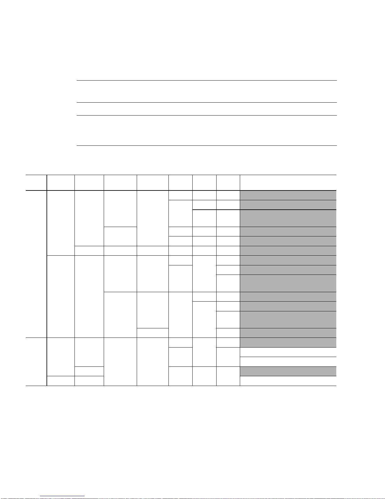
summarizes the behavior of SPARC64 V floating-point hardware depending on
FSR.NS.
TABLE B-5
FSR.NSDenorm :
Norm
1
No Yes
0
Yes n/ a
No Yes
1
Yes — TABLE B-6
Note –
The result and behavior of SPARC64 V of the shaded column in the tables
Table B-5 and Table B-6 conform to IEEE754-1985 standard.
Note –
Throughout Table B-5 and Table B-6, lowercase exception conditions such as
nx, uf, of, dv and nv are nontrapping IEEE 754 exceptions. Uppercase exception
conditions such as NX, UF, OF, DZ a nd NV are trapping IEEE 754 exceptions.
Floating-Poi nt Exceptional C onditions and R esults
Result
Denorm
No —————Confo rms to IEEE754-1985
No ———
1. One of the operands is a denormalized number, and the other operand is a normal or a denormalized number
(non- zero, non-NaN, and non-infinity).
2. The result before rounding turns out to be a denormalized number.
3. Dmin = denormalized minimum.
4. If the FPop is either
not generate an unfinished_FPop and generates a result according to IEEE754-1985 standard.
5. Nmax = normalized maximum.
Pessimistic
2
Zero
Pessimistic
Overflow UFM OFM NXM Re su lt
1 ——
Yes
—
0 — 1 NX
— 0
No 1 ——UF
0 ——
Yes —
1
01
—
— UF
0 uf + nx, a signed zero, or a signed
1 —
No Yes —
01
0
No ——
1 ——
0 — 1NX
——
FADD{s,d
}, or
FSUB{s,d
} and the operation is 0 ± denormalized number, SPARC64 V does
0 uf + nx, a signed zero
UF
uf + nx, a signed zero, or a signed
3
Dmin
unfinished_FPop
4
NX
Dmin
OF
NX
of + nx, a signed infinity, or a
signed Nmax
unfinished_FPop
5
UF
Conforms to IEEE754-1985
66 SPARC JPS1 Implementation Supplement: Fujitsu SPARC64 V • Release 1.0, 1 July 2002
Page 78

TABLE B-6
describes how SPARC64 V behaves when FSR.NS = 1 (nonstandard mode).
TABLE B-6
Operations op1= denorm
Nonarithmetic Operations Under FSR.NS = 1
op2=
denorm UFM NXM DVM NVM Result
FsTOd — Yes — 1 ——NX
0 ——nx, a signed zero
FdTOs — Yes 1 ———
01——NX
0 ——uf + nx, a signed zero
FADDs,
FSUBs,
FADDd,
FSUBd
Yes No
No Yes 1 ——NX
—
1 ——NX
0 ——nx, op2
0 ——nx, op1
Yes Yes 1 ——NX
0 ——nx, a signed zero
FMULs,
FMULd,
FsMULd
Yes —
—
— Yes 1 ——NX
1 ——NX
0 ——nx, a signed zero
0 nx, a signed zero
FDIVs,
FDIVd
Yes No
1 ——NX
0 ——nx, a signed zero
No Yes — 1 — DZ
—
— 0 — dz, a signed infinity
Yes Yes ——1NV
——0nv, dNaN
FSQRTs,
FSQRTd
—
1. A single precision dNaN is 7FFF.FFFF
Yes and op2
> 0
Yes and op2
< 0
—
1 ——NX
0 ——nx, zero
——1
——0 nv, dNaN
and a double precision dNaN is 7FFF.FFFF.FFFF.FFFF16.
16,
UF
1
NV
Release 1.0, 1 July 2002 F. Chapter B IEEE Std 754-1985 Requirements for SPARC V9 67
Page 79

68 SPARC JPS1 Implementation Supplement: Fujitsu SPARC64 V • Release 1.0, 1 July 2002
Page 80

F.APPENDIX
C
Implementation Dependencies
This appendix summarizes implementation dependencies. In SPARC V9 and SPARC
JPS1, the n otation “IMPL. DEP. #nn:” identifies the definition of an implementation
dependency; the notation “(impl. dep. #nn)” identifies a reference to an
implement ation depen dency. Thes e dependenc ies are describe d by their num ber nn
TABLE C-1
in
document for SPARC64 V
modified to include descriptions of the manner in which SPARC64 V
each impl ementati on dep endency.
on page 70. These numbers have been removed from the body of this
to make the docu ment more readab le.
TABLE C-1
has resolved
has been
Note –
Current SPARC-V9-based Products, Revision 9.x, that d escribes the implementati ondependent design features of all SPARC V9-compliant implementations. Contact
SPARC International for this document at
SPARC International maintains a document, Implementation Characteristics of
home page: www.sparc.org
email: info@sparc.org
C.1 Definition of an Implementation
Dependency
Please refer to Se ction C.1 of Commonality.
69
Page 81

C.2 Hardware Characteristics
Please refer to Se ction C.2 of Commonality.
C.3 Implementation Dependency Categorie s
Please refer to Se ction C.3 of Commonality.
C.4 List of Implementation Dependencies
TABLE C-1
treated in the SPARC64 V
TABLE C-1
Nbr SPARC64 V Implementation Notes Page
1 Software emulation of instructions
2 Number of IU registers
3 Incorrect IEEE Std 754-1985 results
4–5 Reserved.
6 I/O registers privileged status
7 I/O register definitions
provides a complete list of how each implementation dependency is
implementation.
SPARC64 V Implementation Dependencies (1 of 11)
The operating system emulates all instructions that generate
illegal_instruction
SPARC64 V
SPARC64 V supports an additional two global register sets (Interrupt
globals and MMU globals) for a total of 160 integer registers.
See Section B.6, Floating-Point Nonstandard Mode, on page 61 for details.
This dependen cy is beyon d the scope o f this publica tion. It shoul d be
defined in each system that uses
This dependen cy is beyon d the scope o f this publica tion. It shoul d be
defined in each system that uses
supports eight register windows (NWINDOWS =8).
unimplemented_FPop
or
exceptions.
SPARC64 V
SPARC64 V
.
.
—
—
62
—
—
8 RDASR/WRASR target registers
See A.50 and A.70 in Commonality for details of implementation-dependent
RDASR/WRASR inst ructions.
70 SPARC JPS1 Implementation Supplement: Fujitsu SPARC64 V • Release 1.0, 1 July 2002
—
Page 82

TABLE C-1
Nbr SPARC64 V Implementation Notes Page
SPARC64 V Implementation Dependencies (2 of 11)
9 RDASR/WRASR privileged status
See A.50 and A.70 in Commonality for details of implementation-dependent
RDASR/WRASR inst ructions.
10–12 Reserved.
13 VER.impl
VER.impl =5 for the
SPARC64 V
processor.
20
14–15 Reserved. —
16 IU deferred-trap queue
SPARC64 V
neither has nor needs an IU deferred-trap queue.
24
17 Reserved. —
18 Nonstandard IEEE 754-1985 results
SPARC64 V
flushes denormal operands and results to zero when
18, 62
FSR.NS = 1. For the treatment of denormalized numbers, please refer to
Section B.6, Floating-Point Nonstandard Mode, on page 61 for details.
19 FPU version, FSR.ve r
FSR.ver =0 for
SPARC64 V
.
18
20–21 Reserved.
22 FPU TEM , cexc, and aexc
SPARC64 V
implements a ll bits in the TEM, cexc, and aexc fields in
19
hardware.
—
23 Floating- point traps
In
SPARC64 V
floating-point traps are always precise; no FQ is needed.
24 FPU deferred-trap queue (FQ)
SPARC64 V
neither has nor needs a floating-point deferred-trap queue.
25 RDPR of FQ with nonexistent FQ
Attempting to execute an RDPR of the FQ causes an
illegal_i nstructi on
24
24
24
exception.
26–28 Reserved. —
29 Address sp ace identifier (AS I) definition s
The ASIs that are supported by
SPARC64 V
are defined in Appendix L,
—
Address Space Identifiers.
30 ASI address decoding
SPARC64 V
supports all o f the listed ASIs.
31 Catastrophic error exceptions
SPARC64 V
contains a watchdog timer that times out after no instruction
117
138
has been committed for a specified number of cycles. If the timer times out,
the CPU tries to invoke an
33
count to reach 2
, the processor enters error_state. Upon an entry to
async_da t a_error
trap. If the counter continues to
error_state, the processor optionally generates a WDR reset to recover
from er ror_s tate .
Release 1.0, 1 July 2002 F. Chapter C Implementation Dependencies 71
Page 83

TABLE C-1
Nbr SPARC64 V Implementation Notes Page
SPARC64 V Implementation Dependencies (3 of 11)
32 Deferred tra ps
SPARC64 V signals a deferred trap in a few of its severe error conditions.
SPARC64 V does not contain a deferred trap queue.
33 Trap prec ision
There are no de ferred trap s in
SPARC64 V
few sev ere erro r c ond it ion s. A ll tra ps tha t o ccu r as th e re sul t of pro gra m
execution a re precise.
34 Interrupt cleari ng
For details o f interrupt ha ndling see Appendix N , Interrupt Ha ndling.
35 Implementation-dependent traps
SPARC64 V
supports the following traps that are implementation
dependent:
interrupt_vector_trap
•
PA_watchpoint
•
VA_watchpoint
•
ECC_error
•
fast_instruction_access_MMU_miss
•
fast_data_access_MMU_miss
•
fast_data_access_protection
•
async_data_error
•
(tt = 06316)
(tt = 06016)
(tt = 06116)
(tt = 06216)
(tt = 06816 through 06B16)
(tt = 06C16 through 06F16)
(tt =04016)
36 Trap priorities
SPARC64 V
’s implementation-dependent traps have the following
priorities:
interrupt_vector_trap
•
PA_watchpoint
•
VA_watchpoint
•
ECC_error
•
fast_instruction_access_MMU_miss
•
fast_data_access_MMU_miss
•
fast_data_access_protection
•
async_data_error
•
(priority = 33)
(priority = 16)
(priority =12)
(priority =1)
(priority = 12)
(priority = 12)
(priority = 2)
37, 149
37
other than the trap caused by a
—
39, 39
(tt = 06416 through 06716)
38
(priority = 2)
37 Reset trap
SPARC64 V
38 Effect of reset trap on implementation-dependent registers
See Section O.3, Processor State after Reset and in RED_state, on page 141.
39 Entering err or_s tate o n implementati on-dependent erro rs
CPU watchdog timeout at 2
causes the CPU to enter error_state.
40 Error_state pr ocessor state
SPARC64 V
error_state. Most error-logging register state will be preserved. (See also
impl. dep. #254.)
41 Reserved.
72 SPARC JPS1 Implementation Supplement: Fujitsu SPARC64 V • Release 1.0, 1 July 2002
implements power-on reset (POR) and watchdog reset.
33
ticks, a normal trap, or an SIR at TL = MAXTL
optionally takes a watchdog reset trap after entry to
37
141
36
36
Page 84

TABLE C-1
Nbr SPARC64 V Implementation Notes Page
SPARC64 V Implementation Dependencies (4 of 11)
42 FLUSH ins truction
SPARC64 V
implements the FLUSH instruction in hardwa re.
43 Reserved.
44 Data access FPU t rap
The destination register(s) are unchanged if an access error occurs.
45–46 Reserved.
47 RDASR
See A.50, Read State Register, in Commonality for detail s.
48 WRASR
See A.70, Write State Register, in Commonality for details .
49–54 Reserved.
55 Floating-point underflow detection
FSR_underflow
See
in Section 5.1.7 of Commonality for details.
56–100 Reserved.
101 Maxim um trap level
MAXTL =5.
102 Clean windo ws trap
SPARC64 V
generates a
clean_window
cleaned in software.
103 Prefetch i nstructions
SPARC64 V
implements PREFETCH variations 0–3 and 20–23 with the
following implementation-dependent characteristics:
• The prefe tches have ob servable effects in privileged code.
• Prefet ch varian ts 0–3 do not cau se a
because the prefetch is dropped when a
condition happens. On the other hand, prefetch variants 20–23 cause
data_access_MMU_miss
traps o n TLB m isses.
• All prefetches are for 64-byte cache lines, which are aligned on a 64-byte
boundary.
• See Section A.49, Prefetch Data, on page 57, for implemented variations
and their characteristics.
• Prefetch es will wo rk norm ally if the ASI is ASI_PR IMARY,
ASI_SECONDARY, or ASI_NUCLE US, ASI_PRIMARY_AS_IF_U SER,
ASI_SECONDARY_AS_IF_USE R, a nd their littl e-endian pa irs.
exception; register windows are
fast_data_access_MMU_miss
fast_data_access_MMU_miss
trap,
—
—
—
—
—
20
—
—
104 VER.manu f
VER.manuf = 0004
manufacturing code.
105 TICK register
SPARC64 V
clock cycle.
Release 1.0, 1 July 2002 F. Chapter C Implementation Dependencies 73
. The least significant 8 bits are Fujitsu’s JEDEC
16
implem ents 63 b its o f the TICK register; it increments on every
20
19
Page 85

TABLE C-1
Nbr SPARC64 V Implementation Notes Page
SPARC64 V Implementation Dependencies (5 of 11)
106 IMPDEPn instructions
SPARC64 V
instructions.
uses the IMPDEP2 opcode for the Multiply Add/Subtract
SPARC64 V
also conforms to Sun’s specification for VI S-1 and
VIS-2.
107 Unim plem ented LDD trap
SPARC64 V
implements LDD in hard wa re.
108 Unim plem ented STD trap
SPARC64 V
implements STD in hard wa re.
109 LDDF_mem _address_not_aligned
If the address is word aligne d but not do ubleword alig ned,
generates the
LDDF_mem_address_not_aligned
software emulates the instruction.
110
STDF_mem_address_not_aligned
If the address is word aligne d but not do ubleword alig ned,
generates the
STDF_mem_address_not_aligned
software emulates the instruction.
111
LDQF_mem_address_not_aligned
SPARC64 V
generates an
illegal_i nstruction
processor does not perform the check for
software emulates the instruction.
112
STQF_mem_address_not_aligned
SPARC64 V
generates an
illegal_i nstruction
processor does not perform the check for
software emulates the instruction.
SPARC64 V
exception. The trap handler
SPARC64 V
exception. The trap handler
exception for all LDQFs. The
fp_disabled
exception for all STQFs. The
fp_disabled
. The trap handler
. The trap handler
49
—
—
—
—
—
—
113 Implemented memory models
SPARC64 V
implements Total Store Order (TSO) for all the me mory m odels
specified in PSTATE.MM. See Chapte r 8, Memory Models, fo r details .
114 RED_state trap vector address (RSTVaddr)
RSTVaddr is a constant in
VA=FFFF FFFF F000 0000
PA=07FF F000 0000
16
SPARC64 V
and
16
, where:
115 RED_state processor state
See RED_state on page 36 for details of implementation-specific actions in
RED_state.
116 SIR_enable control flag
See Section
A.60 SIR in
Commonality for details.
117 MMU disabled prefetch behavior
Prefetch and nonfaul ting Load always succeed when th e MMU is disabled .
118 Identifying I/O locations
This dependen cy is beyon d the scope o f this publica tion. It shoul d be
defined in a system that uses
74 SPARC JPS1 Implementation Supplement: Fujitsu SPARC64 V • Release 1.0, 1 July 2002
SPARC64 V
.
42
36
36
—
91
—
Page 86

TABLE C-1
Nbr SPARC64 V Implementation Notes Page
SPARC64 V Implementation Dependencies (6 of 11)
119 Unimplemented values f or PSTATE.MM
Writing 11
model. However, the encoding 11
of
SPARC64 V
into PSTATE.MM causes the machine to use the TSO memory
2
should not be used, since future versions
2
may use this encoding for a new memory model.
120 Coherenc e and atomicity of memory operat ions
Although SPARC64 V implements the UPA-based cache coherency
mechanism, th is dependen cy is beyond th e scope of t his publication . It
should be defined in a system that uses
SPARC64 V
121 Implementation-dependent memory model
SPARC64 V implements TSO, PSO, and RMO memory models. See
Chapter 8, Memory Models, for details.
Accesses to pages with the E (Volatile) bit of their MMU page table entry set
are also made in program order.
122 FLUSH la tency
Since the FLUSH instruction synchronizes the processor, its total latency
varies depending on many portions of the SPARC64 V processor’s sta te.
Assuming that all prio r instruct ions are complet ed, the la tency of FLUSH is
18 processor cycles
.
123 Input/output (I/O) semantics
This dependen cy is beyon d the scope o f this publica tion. It shoul d be
defined in a system that uses
SPARC64 V
.
124 Imp licit ASI when TL >0
See Section 5.1.7 of Commonality for details.
42
—
.
—
—
—
—
125 Address masking
When PSTATE.AM =1,
SPARC64 V
doe s mask out the high-order 32 bits of
29, 49, 53
the PC when transmitting it to the destination register.
126 Register Windows State Regist ers width
NWINDOWS for
SPARC64 V
is 8; therefore, only 3 bits are implemented for
—
the followin g registers: CWP, CANS AVE, CANRESTORE, OTHERWIN. I f an
attempt is made to write a value greater than NWINDOWS − 1 to any of these
registers, the extraneous upper bits are discarded. The CLEANWIN re gis te r
contains 3 bits.
127–201 Reserved.
202
fast_ECC_error
fast_ECC_error trap is not implemented in
203 Dispatch C ontrol Register bits 13:6 and 1
SPARC64 V
204 DCR bits 5:3 and 0
SPARC64 V
205 Instructio n Trap Register
SPARC64 V
Release 1.0, 1 July 2002 F. Chapter C Implementation Dependencies 75
trap
SPARC64 V
does not implement DCR.
does not implement DCR.
implements the Instruction Trap Register.
—
.
22
22
24
Page 87

TABLE C-1
Nbr SPARC64 V Implementation Notes Page
SPARC64 V Implementation Dependencies (7 of 11)
206 SHUTDOWN in struction
In privileged mode the SHUTDOWN instruction executes as a NOP in
SPARC64 V
.
207 PCR regis ter bits 47:32, 26:17, and bit 3
SPARC64 V
uses these bits for the following purposes:
• Bits 47:32 for set/clear/show status of overflo w (OVF).
• Bit 26 for validity of OVF field (OVRO).
• Bits 24:22 for number of counter pair (NC).
• Bits 20:18 for counter selector (SC).
• Bit 3 f or validity of SU/SL field (ULRO).
Other im plement ation- depende nt bits a re read as 0 and writes to them are
ignored.
208 Ordering of er rors captured in instruction execut ion
The order in which errors are captured duri ng instructio n execution is
implementation dependent. Orderi n g can be in program order or in order o f
detection.
209 Software intervention after instruction-induced error
Precision of the trap to signal an instruction-induced error for which
recovery requires software intervention is implementation dependent.
210 ERROR output signal
The causes and the semantics of ERROR output signal are implementation
dependent.
58
20, 21,
201
—
—
—
211 Error logging registers’ inform ation
The information that the error logging registers preserves beyond the reset
induced by an ERROR signal is implementation dependent.
212 Trap with f atal error
Generation of a trap along with ERROR signal assertion upon detection of a
fatal error is implementation dependent.
213 AFSR.PRIV
SPARC64 V
does no t impl ement th e AFSR.PRIV bit.
214 Enable/disable control for deferred traps
SPARC64 V
does not implement a control feature for deferred traps.
215 Error barrier
DONE and RETRY instructio ns may impli citly provide an er ror barrier
function as MEMBAR #Sync. Whe ther DONE and RETRY instruct ions provide
an error barrie r is implem entation de pendent.
216
217
data_access_error
data_access_error
instruction_access_error
instruction_access_error
trap precision
trap is alwa ys precise in
trap is always precise in
trap precision
SPARC64 V
SPARC64 V
—
—
—
—
—
—
.
—
.
76 SPARC JPS1 Implementation Supplement: Fujitsu SPARC64 V • Release 1.0, 1 July 2002
Page 88

TABLE C-1
Nbr SPARC64 V Implementation Notes Page
SPARC64 V Implementation Dependencies (8 of 11)
218
async_data_error
async_data_error
trap is implemented in
SPARC64 V
, using tt =4016. See
Appendix P for details.
) allocation
219 Asynchronous Fault Address Register (
SPARC64 V
• VA = 00
• VA = 08
implements two AFARs:
for an error occurring in D1 cache.
16
for an error occurring in U2 cache.
16
AFAR
220 Addition of logging and control registers for error handling
SPARC64 V
implements various features for sustaining reliability. See
Appendix P for details.
221 Special/signalling ECCs
The method to generate “special” or “signalling” ECCs and whether
processor-ID is embedded into the data associated with special/signalling
ECCs is implementation dependent.
222 TLB organization
SPARC 64 V has the foll owing TLB o rganization:
• Level-2 micro ITLB (uITLB), 32-way fully associative
• Level-1 micro DTLB (uDTLB), 32-way fully associative
• Level-2 IMMU-TLB—consisting of sITLB (set-associative Instruction TLB)
and fITLB (fully associative Instruction TLB).
• Level-2 DMMU-TLB—consisting of sDTLB (set-associative Data TLB) and
fDTLB (fully associative Data TLB).
223 TLB multiple-hit detection
On SPARC64 V, TLB multiple hit detection is supported. However, the
multiple hit is not detected at every TLB reference. When the micro-TLB
(uTLB), which is the cache of sTLB and fTLB, matches the virtual address,
the multiple hit in sTLB and fTLB is not detect ed. The mu ltiple hit is
detected only when the micro-TLB mismatches and the main TLB is
referenced.
39
177, 178
—
—
85
86
224 MMU physical address w idth
The SPARC64 V MMU implements 43-bit physical addresses. The PA field of
the
as 0 and writes to them are ignored. The MMU translates virtual addresses
into 43-bit physical addresses. Each cache tag holds bits 42:6 of physical
addresses.
225 TLB locking of e ntries
In SPARC64 V, when a TTE with its lock bit set is written into TLB through
the Data In register, the TTE is automatically written into the corresponding
fully associat ive TLB and locked in th e TLB. Other wise, the TTE is written
into the corresponding sTLB of fTLB, depending on its page size.
226 TTE support for CV bit
SPARC64 V
virtually inde xed caches, unal iasing is su pported by
impl. dep. #232.
Release 1.0, 1 July 2002 F. Chapter C Implementation Dependencies 77
TTE
holds a 43-bit physical address. Bits 46:43 of each TTE always read
does not support the CV bit in TTE. Since I1 and D1 are
SPARC64 V
. See also
86
87
87
Page 89

TABLE C-1
Nbr SPARC64 V Implementation Notes Page
SPARC64 V Implementation Dependencies (9 of 11)
227 TSB number of entries
SPARC64 V
supports a maximum of 16 million entries in the common TSB
and a maximum of 32 million lines the Split TSB.
228 TSB_Hash supplied from TSB or context-ID register
TSB_Hash is generated from the context-ID register in
229 TSB_Base address gener ation
SPARC64 V
generates the TSB_Base address directly from the TLB
Extension R egisters. B y mainta ining comp atibility w ith UltraSPARC I/II,
SPARC64 V provides mode flag MCNTL.JPS1_TSBP. When
MCNTL.JPS1_TSBP =0, the TSB_Base register is used.
230
data_access_exception
SPARC64 generates
data_access_exception
trap
only for the causes listed in
Section 7.6.1 of Commonality.
231 MMU physical ad dress variability
SPARC64 V
supports both 41-bit and 43-bit physical address mode. The
initial width of the phy sical address is controlled by OP SR.
232 DCU Control Register CP and CV bits
SPARC64 V
does not implement CP and CV bits in the DCU Control
Register. See also impl. dep. #226.
233 TSB_Hash field
SPARC64 V
does not implement TSB_Hash.
SPARC64 V
88
88
.
88
89
91
23, 91
92
234 TLB replacement algorithm
For fTLB, SPARC64 V implements a pseudo-LRU. For sTLB, LRU is used.
235 TLB data access address assignment
The MMU TLB data-access address assignment and the purpose of the
address are implementation dependent.
236 TSB_Size field width
SPARC64 V
In
, TS B_Siz e is 4 bits wide, occupying bits 3:0 of the TSB
register. The maximum number of TSB entries is, therefore, 512 × 2
entries).
237 DSFAR/DSFSR for J MPL/RET URN
mem_address_not_aligned
A
mem_address_not_ a ligned
exception that occurs during a JMPL or RETURN
instruction does not update either the D-SFAR or D-SFSR regi ste r.
238 TLB page offset for large page sizes
SPARC64 V
On
, even for a large page, written data for TLB Data Register is
preserved for bits representing an offset in a page, so the data previously
written is returned regardless o f the pa ge size.
239 Register access by ASIs 55
In
SPARC64 V
, VA<63:19> of IM MU ASI 5516 and DMMU ASI 5D16 are
and 5D
16
ignored. An access to virtual addresses 40000
access 00000
to 20FF8
16
16
93
94
97
15
(16M
89, 97
87
16
to 60FF816 is treated as an
16
92
78 SPARC JPS1 Implementation Supplement: Fujitsu SPARC64 V • Release 1.0, 1 July 2002
Page 90

TABLE C-1
Nbr SPARC64 V Implementation Notes Page
SPARC64 V Implementation Dependencies (10 of 11)
240 DCU Control Register bits 47:41
SPARC64 V
access in speculative paths.
241 Address Masking and
SPARC64 V
242 TLB lock bit
In SPARC64 V, only the fITLB and the fDTLB support the lock bit. The lock
bit in sITLB and sDTLB is read as 0 and writes to it are ignored.
243 Interrupt Vector Dispatch Status Register BUSY/NACK pairs
SPARC64 V
In
Vector Dispatch Status Register.
244 Data Watchpoint Reliability
No impleme nt ation -d ep ende nt fea tures of
of data watchpoints.
245 Call/Branch displacement encoding in I-Cache
SPARC64 V
In
(BPcc, FBPfcc , Bicc, BPr) instruction in an instruction cache are identical
to the architectural encoding (as they appear in main memory).
246 VA<38:29> for Interrupt Vector Dispatch Register Access
SPARC64 V
Dispatch Register is written.
uses bit 41 for WEAK_SPCA, which e nables/di sables m emory
DSFAR
writes zeroes to the more significant 32 bits of DSFAR.
, 32 BUSY/NACK pairs are implemented in the Interrupt
SPARC64 V
, the least significant 11 bits (bits 10:0) of a CALL or branch
ignores all 10 bits of VA<38:29> when the Interrupt Vector
reduce the reliability
23
—
87
136
24
24
136
247 Interrupt Vector Receive Register SID fields
SPARC64 V
packet.
248 Conditions for
SPARC64 V
under the standard conditions described in Commonality Section 5.1.7.
249 Data watchpoin t for Partial Sto re instruction
Watchpoint exceptions on Partial Store instructions occur conservatively on
SPARC64 V
nonzero value (watchpoint enabled). The byte store mask (r[rs2]) in the
Partial Store ins truction is ign ored, and a wat chpoint ex ception can occur
even if the mask is zero (that is, no store will take place).
250 PCR accessibility when PSTATE.PRIV = 0
In
SPARC64 V
determined by PCR.PRIV. If PSTATE.PRIV =0 and PCR.PRIV =1, an
attempt to execute either RDPCR or WRPCR will cause a
exception. If PSTATE.PRIV =0 and P CR.PR IV =0, RDPCR operates without
privilege vio lation and WRPCR generates a
when an attempt is made to change (that is, write 1 to) PCR.P RIV.
251 Reserved. —
obtains the interrupt source identifier SID_L from the UPA
fp_exception_other
triggers
. The DCUCR Data Watchpoint masks are only checked for
fp_exception_other
, the accessibility of PCR when PSTATE.PRIV =0 is
unfinished_FPop
with
with trap type
privileged_action
unfinish ed_FPop
privileged_action
exception only
136
18
57
20, 22, 58
Release 1.0, 1 July 2002 F. Chapter C Implementation Dependencies 79
Page 91

TABLE C-1
Nbr SPARC64 V Implementation Notes Page
SPARC64 V Implementation Dependencies (11 of 11)
252 DCUCR.DC (D ata Cache Enable)
SPARC64 V
does not implement DCUCR.DC.
253 DCUCR.IC (Instruction Cache Enable)
SPARC64 V does not implement DCUCR.IC.
254 Means of e xiting error_state
The standard behavior of a
SPARC64 V
error_state is to reset itself by internally generating a
(WDR). How ever, OPSR can be set so that when error_state is entere d, the
processor remains halted in error_state instead of generating a
255
watchdog_reset
LDDFA with ASI E 0
.
or E116 and misaligned destination register number
16
No exception is generated based on the destination register rd.
256
LDDFA with ASI E0
For LDDFA with ASI E0
or E116 and misali gned memo ry address
16
or E11 and a memory address aligned on a 2n-byte
16
boundary, a SPARC64 V processor behaves as follows:
n ≥ 3 (≥ 8-byte alignment): no exception related to memory address
alignment is generated.
n = 2 (4-byte al ignment):
LDDF_mem_address_not_aligned
generated.
n ≤ 1 (≤ 2-byte alignment):
mem_address_not_aligned
generated.
257
LDDFA with ASI C0
For LDDFA with C0
n
-byte boundary, a SPARC64 V processor behaves as follows:
a 2
–C5
16
C5
–
16
16
16
or
or
C8
CD16 and misaligned memory address
–
16
C8
CD16 and a memory address aligned on
–
16
n ≥ 3 (≥ 8-byte alignment): no exception related to memory address
alignment is generated.
n = 2 (4-byte al ignment):
LDDF_mem_address_not_aligned
generated.
n ≤ 1 (≤ 2-byte alignment):
mem_address_not_aligned
generated.
CPU up on en try i nto
watchdog_reset
exception is
exception is
exception is
exception is
24
24
37, 146
120
120
120
258
ASI_SERIAL_ID
SPARC64 V provides an identification code for each processor.
80 SPARC JPS1 Implementation Supplement: Fujitsu SPARC64 V • Release 1.0, 1 July 2002
119
Page 92

F.APPENDIX
D
Formal Specification of the Memory
Models
Please refer to Appendi x D of
Commonality
.
81
Page 93

82 SPARC JPS1 Implementation Supplement: Fujitsu SPARC64 V • Release 1.0, 1 July 2002
Page 94

F.APPENDIX
E
Opcode Maps
Please refer to Appendix E in
SPARC64 V
TABLE E-1
(instruction<6:5>)
IMPDEP2
IMPDEP2 (op = 2, op3 = 37
size
instruc tion.
00
01
10
11
Commonality
)
16
00 01 10 11
FMADDs FMSUBs FNMADDs FNMADDs
FMADDd FMSUBd SNMSUBd FNMSUBd
TABLE E-1
.
var (instruction <8:7>)
(not used — reserved)
(reserved for quad operati ons)
lists the opcode map for the
83
Page 95

84 SPARC JPS1 Implementation Supplement: Fujitsu SPARC64 V • Release 1.0, 1 July 2002
Page 96

F.APPENDIX
F
Memory Management Unit
The Memory Ma nagement Unit (MMU) archit ecture of SPARC64 V conf orms to the
MMU architecture defined in Appendix F of
dependency. See Appendix F in
SPARC64 V MMU.
Section numbers in this appendix correspond to those in Appendix F of
Commonality
This appendix describes the implementation dependencies and other additional
information about the SPARC64 V MMU. For SPARC64 V implementations, we first
list the implementation dependency as given in
describe the SPARC64 V implementation.
. Figures and tables, however, are numbered consecutively.
Commonality
Commonality
for the basic definiti ons of the
TABLE C-1
but with some model
Commonality
of
, then
F.1 Virtual Address Translation
IMPL. DEP. # 222
SPARC64 V has the following TLB organization:
■
Level-1 micro ITLB (uITLB), 32-way fully associative
■
Level-1 micro DTLB (uDTLB), 32-way fully associative
■
Level-2 IMMU-TLB consists of sITLB (set-associative Instruction TLB) and
fITLB (fully associative Instruction TLB).
■
Level-2 DMMU-TLB consists of sDTLB (set-associative Data TLB) and fDTLB
(fully associative Data TLB).
TABLE F-1
Hardware contains micro-ITLB and micro-DTLB as the temporary m emory of the
main TLBs, as shown in
are called main TLBs.
shows the organization of SPARC64 V TLBs.
:
TLB
organization is JPS1 implementation dependent.
TABLE F-1
. In contrast to the micro-TLBs, sTLB and fTLB
85
Page 97

The micro-TLBs are coherent to main TLBs and are not visible to software, with
the exception of TLB multiple hit detection. Hardware maintains the consistency
between micro-TLBs and main TLBs.
No other details on micro-TLB are provided because software cannot execute
direct operations to micro-TLB and its configuration is invisible to software.
TABLE F-1
Feature sITLB and sDTLB fITLB and fDTLB
Entries 2048 32
Associativity 2-way set associative Fully associative
Page size supported 8 KB/4MB 8 KB/64 KB/512 KB/4 MB
Locked translation entry Not supported Supported
Unlocked translation entry Supported Supported
IMPL. DEP. #223
Organization of SPARC64 V TLBs
:
Whether TLB multiple-hit detections are supported in JPS1 is
implementation dependent.
On SPARC64 V, TLB multiple hit detection is supported. However, the multiple
hit is not detected at every TLB reference. When the micro-TLB (uTLB), which is
the cache of sTLB and fTLB, matches the virtual a ddress, the multiple hit in sTLB
and fTLB is not detected. The multiple hit is detected only when the micro-TLB
mismatches and main TLB is referenced.
F.2 Translation Table Entry (TTE)
IMPL DEP.
in Commonality
TABLE
F-1:
TTE_Data bits 46–43 are implementation
dependent.
On SPARC64 V,
IMPL. DEP. #224
TTE_Data
:
Physical address width support by the MMU is implementation
bits 46:43 are reserved.
dependent in JPS1; minimum PA width is 43 bits.
The SPARC64 V MMU implements 43-bit physical addresses. The PA field of the
TTE
holds a 43-bit physical address. The MMU translates virtual addresses into
43-bit physical a ddresses. Each cache tag holds bi ts 42:6 of physical addres ses.
Bits 46:43 of each TTE always read as 0 and wr ites to them are ignored.
A cacheable access for a physical address ≥ 400 0000 0000
always causes the
16
cache miss for the U2 cache and generates a UPA request for the cacheable access.
The urgent error
ASI_UGESR.SDC
is signalled after the UPA cacheable access is
requested.
86 SPARC JPS1 Implementation Supplement: Fujitsu SPARC64 V • Release 1.0, 1 July 2002
Page 98

The physical address length to be passed to the UPA interface is 41 bits or 43 bits,
as designated in the
ASI_UPA_CONFIG.AM
in
ASI_UPA_CONFIG.AM
field. When the 41-bit PA is specified
, the most signific ant 2 bits of the C PU inter nal phys ical
address are discarded and only the remaining le ast significant 41 bits are passed
to the UPA ad dress bus. If the discarded most sign ificant 2 bits are not 0, th e
urgent error
ASI_UGESR.SDC
is detected afte r the invalid ad dress transfer to the
UPA interface. Otherwise, when the 43-bit PA is specified in
ASI_UPA_CONFIG.AM,
the entire 43 bits of CPU internal physical address are
passed to the UPA address bus.
IMPL. DEP. # 238
:
When page offset bits for larger page size (PA<15:13>, PA<18:13>,
and PA<21:13> for 64-Kbyt e, 512-Kbyte, an d 4-Mbyte page s, respectively) are stored
in the TLB, it is implementation dependent whether the data returned from those
fields by a Da ta Access read are zero or th e data previously written to th em.
On SPARC64 V, the data returned from PA<15:13>, PA<18:13>, and PA<21:13> for
64-Kbyte, 512-Kbyt e, and 4-Mbyte pages , respectively, by a Dat a Access read are
the data previously written to them.
IMPL. DEP. # 225
:
The mechanism by which entries in TLB are locked is
implementation dependent in JPS1.
In SPARC64 V, when a TTE with its lock bit set is written into TLB through the
Data In register, the TTE is automatically written into the corresponding fully
associative TLB and locked in the TLB. Otherwise, the TTE is written into the
corresponding sTLB or fTLB, depending on its page size.
IMPL. DEP. #242
:
An implementation containing multiple TLBs may implement the L
(lock) bit in all TLBs but is only required to implement a lock bit in one TLB for each
page size. If the lock bit is not implemented in a particular TLB, it is read as 0 and
writes to it are ignored.
In SPARC64 V, only the fITLB and the fDTLB support the lock bit as described in
TABLE F-1
. The lock bit in sITLB and sDTLB is read as 0 and writes to it are
ignored.
IMPL. DEP. # 226
dependent in JP S1. When the CV bit in
has virtually indexed caches, the implementation should support hardware
unaliasing for the caches.
In SPARC64 V, no TLB supports the CV bit in
unaliasing for the caches. The CV bit in any
are ignored.
Release 1.0, 1 July 2002 F. Chapter F Memory Management Unit 87
:
Whether t he CV bit is supported in
TTE
is not provided and the implementation
TTE
TLB
entry is read as 0 and write s to it
TTE
is implementation
. SPARC64 V support s hardware
Page 99

F.3.3 TSB Organization
IMPL. DEP. #227
dependent in JPS1. See impl . dep. #228 for the limitati on of
registers.
SPARC64 V supports a maximum of 16 million lines in the common TSB and a
maximum 32 million lines in the split TSB. The maximum number N in
FIGURE
F-4 of
:
The maximum number of entries in a TSB is implementation
Commonality
is
16 million (16 * 220).
F.4.2 TSB Pointer Formation
IMPL. DEP. #228
from a context-ID register is implementation dependent in JPS1. Only for cases of
direct hash with context-ID can the width of the
bits.
On SPARC64 V,
TSB_size
the
IMPL. DEP. #229
exclusive-ORing the TSB Base Register and a TSB Extension Register or by taking the
TSB_Base
dependent in JPS1. This implementation dependency is only to maintain
compatibility with the TLB miss handling software of UltraSPARC I/II.
:
Whether
TSB_Hash
field is 4 bits.
:
Whether the implementation generates the TSB Base address by
field directly from the TSB Extension Register is implementation
TSB_Hash
is supplied from a context-ID register. The width of
TSB_size
is supplied from a TSB Extension Register or
TSB_size
field be wider than 3
in TSB
On SPARC64 V, when
generated by taking
ASI_MCNTL.JPS1_TSBP
TSB_Base
field directly from the TSB Extension Register.
= 1, the TSB Base address is
TSB Point er Formation
On SPA RC64 V, the nu mber N in the follow ing equa tions ranges f rom 0 to 1 5; N is
defined to be the
SPARC64 V supports the TSB Base from TSB Extension Registers as follows when
ASI_MCNTL.JPS1_TSBP
For a shared TSB (TSB Register split field = 0):
8K_POINTER = TSB_Extension[63:13+N] (VA[21+N:13] ⊕ TSB_Hash)
0000
64K_POINTER = TSB_Extension[63:13+N]
0000
For a split TSB (TSB Register split field = 1):
88 SPARC JPS1 Implementation Supplement: Fujitsu SPARC64 V • Release 1.0, 1 July 2002
TSB_Size
=1.
field of the TSB Base or TSB Extension Register.
(VA[24+N:16] ⊕ TSB_Hash)
Page 100

8K_POINTER = TSB_Extension[63:14+N] 0 (VA[21+N:13] ⊕ TSB_Hash)
0000
64K_POINTER = TSB_Extension[63:14+N] 1
TSB_Hash) 0000
Value of TSB_Hash for both a shared TSB and a split TSB
When 0 <= N <= 4,
TSB_Hash = context_register[N+8:0]
Otherwise, when 5 <= N <= 15,
TSB_Hash[ 12:0 ] = context_register[ 12:0 ]
TSB_Hash[ N+8:13 ] = 0 ( N-4 bits zero )
F.5 Faults and Traps
IMPL. DEP. # 230
dependent in JPS1, but there are several mandatory causes of
trap.
SPARC64 V signals a
Commonality. However, caution is needed to deal with an invalid ASI. See
Section F.10.9 for details.
: The cause of a
data_access_exception
data_access_exception
for the causes, as defined in F.5 in
(VA[24+N:16] ⊕
trap is implementation
data_access_exception
IMPL. DEP. # 237
captured wh en
: Whether th e fault status and/or address (DSFSR/DSFAR) are
mem_address_not_aligned
is generated during a JMPL or RETURN
instruction is implementation dependent.
On SPARC64 V, the fault sta tus and address (DSFSR/DSFAR) are not captured
when a
mem_address_not_aligned
exception is generated during a JMPL or RETURN
instruction.
Additional information:
instruction_access_error
TABLE
to those in
F-2 of Commonality. A modification (the two traps are added) of
On SPARC64 V, the two precise traps—
data_access_error
and
—are recorded b y the MMU in addit ion
that table is sho wn belo w.
TABLE F-2
Ref #Trap Name Trap Cause I-SFSR
1.
Release 1.0, 1 July 2002 F. Chapter F Memory Management Unit 89
MMU Trap Typ es, Cau ses, and Stored Sta te Reg ister Up date Pol icy
fast_instruction_access_MMU_miss
I-TLB miss X2 X 6 416–67
Registers Updated
(Stored State in MMU)
I-MMU
Tag
Access
D-SFSR,
SFAR
D-MMU
Tag
Access Trap Type
16
 Loading...