

Page 1

SPARC® Enterprise T5440 Server Getting Started Guide
This guide describes the minimum steps you must perform to get your server to power on and boot for the first time using the
preinstalled Solaris™ Operating System (Solaris OS).
FIGURE 1 SPARC Enterprise T5440 Server
Shipping Contents
Quantity Item
1Server
2 RJ-45 Ethernet cable
1 RJ-45 to DB-25 adapter (crossover)
1 RJ-45 to DB-9 adapter (crossover)
1 Wrist strap
4 Power cords (packaged separately)
1 Rackmounting kit with cable management
assembly
Quick Setup Instructions
For quick installation and configuration, follow these steps. For more detailed information, refer to the complete online product
documentation set at: http://www.fujitsu.com/sparcenterprise/manual/
Understand the following information before you set up the server for the first time:
■ Choose the best instructions for your situation – These quick setup instructions work for any networking environment, and
require the use of a terminal device for connectivity to a serial port. If you have a networking environment running DHCP, you
can configure your system using the Ethernet management port. To take advantage of the DHCP setup method, refer to the online
installation guide instead of these instructions.
■ Set aside sufficient time – Installation times vary, but if you are performing these setup instructions for the first time, plan to
spend about 45 to 75 minutes to complete all of these instructions. Additional time might be required for installing optional
hardware and rackmounting kits.
■ Gather your configuration information – During the configuration, you are prompted for time zone and networking parameters
that are specific to your environment. For a list of information you need, see Step 9.
■ Obtain a terminal device – You configure this rackmountable server through the service processor (SP) using the built-in serial
and network management ports, and not through a graphical interface and keyboard. For more information about the terminal
device, see Step 3.
■ Do not apply power at this time – This system includes a service processor (SP) that is used to configure and boot the main
host server. To properly configure the host server and view SP messages, do not apply AC power to the server until the SP and
host networking connections are made, as described in this guide.
Page 2
1. Unpack the server, and check that you received all of the shipping contents.
2. Place the server in its intended location for verification.
For rackmounting instructions, refer to the instructions included with the rail kit, the service label on the server, and to the
online SPARC Enterprise T5440 Server Installation and Setup Guide.
3. Connect a serial cable between the server’s SER MGT port (
FIGURE 2) and a terminal device.
This connection provides your initial communication with the service processor (SP).
The terminal device can be a terminal, a terminal server, or a laptop with terminal emulation software running. The device must
be set up to communicate using 9600 baud, 8 bit, no parity, 1 stop bit. A null modem configuration is needed, meaning the
transmit and receive signals are reversed (crossed over) for DTE to DTE communications. You can use the supplied RJ-45
crossover adapters with a standard RJ-45 cable to achieve the null modem configuration.
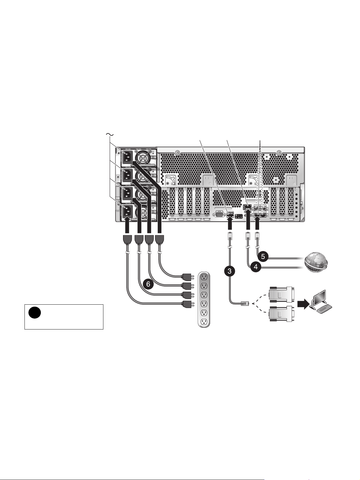
FIGURE 2 Server Connections
SER MGT
RJ-45
NET MGT
RJ-45
NET 0 to NET 3
RJ-45
Host to Ethernet
SP to Ethernet
(Optional)
RJ-45 to DB-25
crossover
adapter
n
Numbered cables
correspond to setup steps.
RJ-45 to DB-9
crossover
adapter
Terminal
device
4. (Optional) Connect an Ethernet cable between the server’s Net MGT port (FIGURE 2) and the network to which future
connections to the SP and host will be made.
After the initial configuration of the system using the SP SER MGT port, communication with the SP and host is usually
performed through this Ethernet interface.
5. Connect an Ethernet cable between one of the server’s NET ports (
FIGURE 2) and the network to which the server will
communicate.
6. Plug the power cords into the power supplies and into a power source.
Note - Only two power connections are required for operation. Use four power connections and two circuits for redundancy.
When power is applied, the SP initializes and power supply LEDs illuminate. After a few minutes, the SP login prompt appears
on the terminal device. The host is not initialized or powered on at this time.
Page 3

7. At the terminal device, log in to the SP as root with the password changeme.
SUNSP00144FAC732F login: root
Password: changeme
. . .
->
After a brief delay, the SP prompt is displayed (->). At this point, there are many commands you can perform using the
Integrated Lights Out Manager interface.
Additional SP information, such as how to change the password and how to set up the SP network parameters is available in the
online documentation set.
8. Power on the server and redirect the host output to display on the serial terminal device:
-> start /SYS
Are you sure you want to start /SYS (y/n)? y
-> start /SP/console
Are you sure you want to start /SP/CONSOLE (y/n)? y
Serial console started. To stop, type #.
. . .
After you start the SP console, the server initialization takes approximately 20 minutes to complete.
9. When prompted, follow the onscreen instructions and enter the following configuration information.
You will be prompted to confirm the configuration several times, enabling confirmation and changes. If you are not sure how to
respond to a particular value, you can accept the default, and make future changes when the Solaris OS is running.
Parameter Description
Language Select a number from the displayed language list.
Locale Select a number from the displayed locale list.
Ter m i n al Ty p e Select a terminal type that corresponds with your terminal device.
Network? Select Yes.
Multiple Network Interfaces Select the network interfaces that you plan to configure. If you are not sure, select the first one in the
list.
DHCP? Select Yes or No according to your network environment.
Host Name Enter the host name for the server.
IP Address Enter the IP address for this Ethernet interface.
Subnet? Select Yes or No according to your network environment.
Subnet Netmask (If subnet was Yes) Enter the netmask for the subnet for your network environment.
IPv6? Specify whether or not to use IPv6. If you are not sure, select No to configure the Ethernet interface
for IPv4.
Security Policy Select either standard UNIX
Confirm Review the onscreen information and change it if needed. Otherwise, continue.
Name Service Select the name service according to your network environment.
Note–If you select a name service other than None, you will be prompted for additional name service
configuration information.
NFSv4 Domain Name Select the type of domain name configuration according to your environment. If you are not sure,
select Use the NFSv4 domain derived by the system.
Time Zone (Continent) Select your continent.
Time Zone (Country or Region) Select your country or region.
Time Zone Select the time zone.
Date and Time Accept the default date and time or change the values.
root Password Enter the root password twice. This password is for the superuser account for the Solaris OS on this
server. This password is not the SP password.
®
security (No) or Kerberos Security (Yes). If you are not sure, select No.
When the configuration menus are completed, the server reboots and displays the Solaris login prompt.
Page 4

10. Log in to the server and explore the capabilities.
There are many commands you can use to verify the functionality of the system. The following list describes a few of them:
■ showrev – Displays the host name and system architecture information. Use the -a option with this command to see the
patches that are installed.
■ psrinfo – Displays information about the number and status of the processors and cores in the host.
■ prtdiag – Displays system configuration and diagnostic information.
Review the Solaris OS man pages and documentation for more details.
Accessing Important Information for SPARC Enterprise Series Servers
Before you deploy your server, check for the Product Notes for your server and other important information on the following
websites.
Global Site
http://www.fujitsu.com/sparcenterprise/manual/notes/
North American Site
https://download.computers.us.fujitsu.com/
Japanese Site
http://primeserver.fujitsu.com/sparcenterprise/manual/notes/
Accessing Documentation
The following websites provide the latest versions of SPARC Enterprise Series manuals:
Global Site
http://www.fujitsu.com/sparcenterprise/manual/
North American Site
https://download.computers.us.fujitsu.com/
Japanese Site
http://primeserver.fujitsu.com/sparcenterprise/manual/
Reader's Comments Regarding This Manual
If you have any comments or requests regarding this manual, or if you find any unclear statements in the manual, please state your
points specifically, and forward it to the system engineer (SE) in charge, or your sales representative.
Copyright 2008 Sun Microsystems, Inc. All rights reserved. FUJITSU LIMITED provided technical input and review on portions of this material.
Copyright 2008 Sun Microsystems, Inc. Tous droits réservés. Entrée et revue tecnical fournies par FUJITSU LIMITED sur des parties de ce matériel.
Manual Code C120-E504-01XA
Part No. 875-4447-10
September 2008, Revision A
Page 5

Page 6

Page 7

Page 8

 Loading...