

Fujitsu Sparc Enterprise T5120, Sparc Enterprise T5220 Installation Manual


SPARC EnterpriseTMT5120 and
T5220 Servers Installation Guide
Manual Code C120-E462-03EN
Part No. 875-4191-12
July 2009, Revision A

Copyright ©2009 SunMicrosystems, Inc.,4150 NetworkCircle, Santa Clara, California 95054, U.S.A. All rights reserved.
FUJITSU LIMITEDprovided technicalinput andreview on portions of this material.
Sun Microsystems,Inc. andFujitsu Limitedeach ownor control intellectualproperty rightsrelating to productsand technologydescribed in
this document,and suchproducts, technologyand thisdocument are protectedby copyrightlaws, patentsand otherintellectual property laws
and internationaltreaties. Theintellectual property rightsof SunMicrosystems, Inc.and FujitsuLimited insuch products, technologyand this
document include,without limitation,one ormore ofthe UnitedStates patentslisted athttp://www.sun.com/patents andone ormore
additional patentsor patentapplications inthe UnitedStates orother countries.
This documentand theproduct andtechnology towhich itpertains are distributedunder licensesrestricting theiruse, copying,distribution,
and decompilation.No partof suchproduct ortechnology, or of this document, may be reproduced inany formby anymeans withoutprior
written authorizationof FujitsuLimited andSun Microsystems,Inc., andtheir applicablelicensors, ifany. The furnishing of this document to
you doesnot giveyou anyrights orlicenses, expressor implied,with respect tothe productor technologyto whichit pertains,and this
document doesnot containor represent anycommitment ofany kindon thepart ofFujitsu Limitedor SunMicrosystems, Inc.,or anyaffiliate of
either ofthem.
This documentand theproduct andtechnology describedin thisdocument mayincorporate third-party intellectualproperty copyrightedby
and/or licensedfrom suppliersto FujitsuLimited and/orSun Microsystems, Inc.,including softwareand fonttechnology.
Per theterms ofthe GPLor LGPL,a copyof thesource codegoverned bythe GPLor LGPL,as applicable,is availableupon request bythe End
User.Please contactFujitsu Limitedor SunMicrosystems, Inc.
This distributionmay includematerials developedby thirdparties.
Parts ofthe productmay bederived from BerkeleyBSD systems,licensed fromthe Universityof California.UNIX isa registered trademarkin
the U.S.and inother countries,exclusively licensedthrough X/OpenCompany, Ltd.
Sun™, SunMicrosystems™, theSun logo
SunSolveSM, CoolThreads™,and J2EE™,are trademarks or registered trademarksof SunMicrosystems, Inc. or its subsidiaries in the U.S. and
other countries.
©
, Java™,Netra™, Solaris™,Sun StorageTek™,docs.sun.comSM, OpenBoot™,SunVTS™, SunFire™,
Fujitsu andthe Fujitsulogo areregisteredtrademarks ofFujitsu Limited.
All SPARCtrademarks areused underlicense andare registered trademarksof SPARCInternational, Inc.in theU.S. andother countries.
Products bearingSPARC trademarksare based upon architecture developedby SunMicrosystems, Inc.
SPARC64 isa trademarkof SPARCInternational, Inc.,used underlicense byFujitsu Microelectronics,Inc. andFujitsu Limited.
SSH isa registered trademarkof SSHCommunications Securityin theUnited Statesand incertain otherjurisdictions.
The OPENLOOK andSun™ GraphicalUser Interfacewas developedby SunMicrosystems, Inc.for itsusers andlicensees. Sunacknowledges
the pioneeringefforts ofXerox in researchingand developingthe conceptof visualor graphicaluser interfacesfor thecomputer industry.Sun
holds anon-exclusive licensefrom Xerox tothe XeroxGraphical UserInterface, whichlicense alsocovers Sun’slicensees whoimplement OPEN
LOOK GUIsand otherwisecomply withSun’s writtenlicense agreements.
United StatesGovernment Rights- Commercialuse. U.S.Government usersare subject to the standardgovernment userlicense agreementsof
Sun Microsystems,Inc. andFujitsu Limitedand theapplicable provisions ofthe FARand itssupplements.
Disclaimer: Theonly warrantiesgranted byFujitsu Limited,Sun Microsystems,Inc. orany affiliate ofeither ofthem inconnection withthis
document orany productor technology described herein arethose expressly setforth inthe licenseagreement pursuant to which theproduct or
technology isprovided.
EXCEPT ASEXPRESSLY SETFORTH IN SUCH AGREEMENT,FUJITSU LIMITED,SUN MICROSYSTEMS,INC. ANDTHEIR AFFILIATES
MAKE NOREPRESENTATIONSOR WARRANTIESOF ANYKIND (EXPRESSOR IMPLIED)REGARDING SUCHPRODUCT OR
TECHNOLOGY ORTHIS DOCUMENT,WHICH ARE ALL PROVIDEDAS IS, AND ALLEXPRESS ORIMPLIED CONDITIONS,
REPRESENTATIONSAND WARRANTIES,INCLUDING WITHOUTLIMITATION ANY IMPLIED WARRANTYOF MERCHANTABILITY,
FITNESS FORA PARTICULAR PURPOSEOR NON-INFRINGEMENT, ARE DISCLAIMED, EXCEPT TOTHE EXTENTTHATSUCH
DISCLAIMERS AREHELD TOBE LEGALLYINVALID.
Unless otherwiseexpressly setforth insuch agreement, tothe extentallowed byapplicable law,in noevent shallFujitsu Limited,Sun
Microsystems, Inc.or anyof theiraffiliates have any liability to any thirdparty underany legaltheory forany lossof revenuesor profits, lossof
use ordata, orbusiness interruptions,or forany indirect,special, incidentalor consequentialdamages, evenif advisedof thepossibility ofsuch
damages.
DOCUMENTATIONIS PROVIDED“AS IS”AND ALLEXPRESS ORIMPLIED CONDITIONS,REPRESENTATIONS AND WARRANTIES,
INCLUDING ANYIMPLIED WARRANTYOF MERCHANTABILITY,FITNESS FORA PARTICULARPURPOSE ORNON-INFRINGEMENT,
ARE DISCLAIMED,EXCEPT TOTHE EXTENTTHAT SUCHDISCLAIMERS AREHELD TOBE LEGALLYINVALID.
Please
Recycle

Copyright ©2009 SunMicrosystems, Inc.,4150 NetworkCircle, Santa Clara, California 95054, Etats-Unis. Tous droits réservés.
Entrée etrevue tecnicalfournies parFUJITSU LIMITEDsur desparties dece matériel.
Sun Microsystems,Inc. etFujitsu Limiteddétiennent etcontrôlent toutesdeux desdroits de propriétéintellectuelle relatifsaux produits et
technologies décritsdans cedocument. Demême, cesproduits, technologieset cedocument sontprotégés par des lois sur le copyright, des
brevets, d’autres loissur lapropriété intellectuelleet destraités internationaux.Les droits depropriété intellectuellede SunMicrosystems, Inc.
et FujitsuLimited concernantces produits,ces technologieset cedocument comprennent, sansque cetteliste soitexhaustive, unou plusieurs
des brevetsdéposés auxÉtats-Unis etindiqués àl’adresse http://www.sun.com/patentsde mêmequ’un ouplusieurs brevetsou applications
brevetées supplémentaires auxÉtats-Unis etdans d’autrespays.
Ce document,le produitet lestechnologies afférents sontexclusivement distribuésavec deslicences quien restreignent l’utilisation,la copie,la
distribution etla décompilation.Aucune partiede ceproduit, deces technologiesou dece documentne peutêtre reproduite sousquelque
forme quece soit,par quelquemoyen quece soit,sans l’autorisationécrite préalablede FujitsuLimited etde SunMicrosystems, Inc.,et deleurs
éventuels bailleursde licence.Ce document,bien qu’ilvous aitété fourni,ne vousconfère aucundroit et aucune licence, expressesou tacites,
concernant leproduit oula technologieauxquels ilse rapporte.Par ailleurs,il necontient nine représente aucunengagement, dequelque type
que cesoit, dela partde FujitsuLimited oude SunMicrosystems, Inc.,ou dessociétés affiliées.
Ce document,et leproduit etles technologiesqu’il décrit,peuvent inclure desdroits depropriété intellectuelle de parties tiercesprotégés par
copyright et/oucédés souslicence pardes fournisseursà FujitsuLimited et/ouSun Microsystems,Inc., ycompris deslogiciels etdes
technologies relativesaux policesde caractères.
Par limitesdu GPLou duLGPL, unecopie ducode sourcerégi parle GPLou LGPL,comme applicable,est surdemande versla finutilsateur
disponible; veuillezcontacter FujitsuLimted ouSun Microsystems,Inc.
Cette distributionpeut comprendre descomposants développéspar destierces parties.
Des partiesde ceproduit pourront êtredérivées dessystèmes BerkeleyBSD licenciéspar l’Universitéde Californie.UNIX estune marque
déposée auxEtats-Unis etdans d’autrespays etlicenciée exclusivementpar X/OpenCompany, Ltd.
Sun™, SunMicrosystems™, lelogo Sun
SunSolveSM, CoolThreads™,et J2EE™sont desmarques de fabrique ou des marques déposéesde SunMicrosystems, Inc., ouses filialesaux
Etats-Unis etdans d’autrespays.
©
, Java™,Netra™, Solaris™,Sun StorageTek™,docs.sun.comSM, OpenBoot™,SunVTS™, SunFire™,
Fujitsu etle logoFujitsu sontdes marquesdéposées deFujitsu Limited.
Toutes lesmarques SPARCsont utiliséessous licenceet sontdes marquesde fabriqueou desmarquesdéposées deSPARCInternational, Inc.
aux Etats-Uniset dansd’autres pays.Les produits portantles marquesSPARC sontbasés surune architecture développéepar Sun
Microsystems, Inc.
SPARC64 estune marquesdéposée deSPARC International,Inc., utiliséesous lepermis parFujitsu Microelectronics, Inc.et FujitsuLimited.
SSH estune marquedéposée registre deSSH CommunicationsSecurity auxEtats-Uniset danscertaines autres juridictions.
L’interfaced’utilisation graphiqueOPEN LOOKet Sun™a étédéveloppée parSun Microsystems, Inc.pour sesutilisateurs etlicenciés. Sun
reconnaît lesefforts de pionniers de Xeroxpour larecherche et le développement du concept des interfaces d’utilisation visuelle ou graphique
pour l’industriede l’informatique.Sun détientune licensenon exclusivede Xeroxsur l’interfaced’utilisation graphiqueXerox, cette licence
couvrant égalementles licenciésde Sunqui mettenten place l’interface d’utilisation graphiqueOPEN LOOKet qui,en outre,se conformentaux
licences écritesde Sun.
Droits dugouvernement américain- logicielcommercial. Les utilisateurs du gouvernement américain sont soumis aux contrats de licence
standard deSun Microsystems, Inc.et deFujitsu Limitedainsi qu’auxclauses applicablesstipulées dansle FARet sessuppléments.
Avis denon-responsabilité: lesseules garantiesoctroyées par Fujitsu Limited, Sun Microsystems, Inc.ou toutesociété affiliéede l’uneou l’autre
entité enrapport avecce documentou toutproduit outoute technologiedécrit(e) dansles présentescorrespondent aux garanties expressément
stipulées dansle contratde licencerégissant leproduit oula technologiefourni(e).
SAUF MENTIONCONTRAIRE EXPRESSÉMENTSTIPULÉE DANSCE CONTRAT, FUJITSULIMITED, SUNMICROSYSTEMS, INC.ET LES
SOCIÉTÉS AFFILIÉESREJETTENT TOUTEREPRÉSENTATIONOU TOUTEGARANTIE, QUELLEQU’EN SOITLA NATURE(EXPRESSE
OU IMPLICITE)CONCERNANT CEPRODUIT,CETTE TECHNOLOGIEOU CEDOCUMENT,LESQUELS SONTFOURNIS ENL’ÉTAT. EN
OUTRE, TOUTESLES CONDITIONS,REPRÉSENTATIONSET GARANTIESEXPRESSES OUTACITES,Y COMPRISNOTAMMENT TOUTE
GARANTIE IMPLICITERELATIVEÀ LAQUALITÉ MARCHANDE,À L’APTITUDEÀ UNEUTILISATIONPARTICULIÈRE OU À
L’ABSENCEDE CONTREFAÇON,SONT EXCLUES,DANS LAMESURE AUTORISÉEPAR LALOI APPLICABLE.
Sauf mentioncontraire expressément stipuléedans cecontrat, dansla mesureautorisée parla loiapplicable, enaucun casFujitsu Limited,Sun
Microsystems, Inc.ou l’unede leursfiliales nesauraient être tenuesresponsables enversune quelconquepartie tierce, sousquelque théorie
juridique quece soit,de toutmanque àgagner oude pertede profit,de problèmes d’utilisationou deperte dedonnées, oud’interruptions
d’activités, oude toutdommage indirect,spécial, secondaire ouconsécutif, mêmesi cesentités ontété préalablementinformées d’unetelle
éventualité.
LA DOCUMENTATION ESTFOURNIE “ENL’ETAT”ET TOUTESAUTRES CONDITIONS,DECLARATIONSET GARANTIESEXPRESSES
OU TACITESSONT FORMELLEMENTEXCLUES, DANSLA MESUREAUTORISEE PARLA LOIAPPLICABLE, YCOMPRIS NOTAMMENT
TOUTE GARANTIEIMPLICITE RELATIVEA LAQUALITE MARCHANDE,A L’APTITUDE A UNE UTILISATIONPARTICULIERE OUA
L’ABSENCEDE CONTREFACON.


Contents
Preface ix
Preparing for Installation 1
Server Overview 1
Server Handling Precautions 3
Input Power Information and Precautions 3
Tools and Equipment Needed 4
Optional Component Installation 5
ESD Precautions 5
Installation Overview 6
Preparing for Installation 8
Installing the Hardware 8
Configuring the Service Processor 9
Configuring the Host Software 10
Cabling Notes for Both Servers 10
Port, Connector, and LED Locations for Both Servers 12
Slide Rail Assembly Notes for Both Servers 15
Cable Management Notes for Both Servers 18
Installing the SPARC Enterprise T5120 and T5220 Servers 19
Installing the Servers in a Rack 19
▼ To Install the Slide Rail Assemblies 20
▼ To Insert and Lock the Server in the Rack 26
v

Installing the Cable Management Arm for Both Servers 27
▼ To Install the Cable Management Arm 28
▼ To Verify the Operation of the Slide Rails and the CMA 32
Connecting the Server Cables for Both Servers 34
To Connect the Service Processor Serial Management Port 35
▼ To Connect the Service Processor Network Management Port 36
▼ To Connect the Ethernet Network Cables 38
▼ To Connect the AC Power Cable to the Server 38
Managing Cables With the CMA 39
▼ To Secure the Server Cables in the CMA 39
Dismounting the Servers 40
Powering On the System 43
Powering On the System for the First Time 43
ILOM System Console 43
ILOM Service Processor 44
▼ To Power On the System for the First Time 44
Enabling the Service Processor Network Management Port 49
Logging Into the Service Processor 51
▼ To Log Into the Service Processor Using the Serial Management Port
51
▼ To Configure the Service Processor Network Management Port 52
▼ To Log Into the Service Processor Using the Network Management
Port 55
Using the Service Processor for Common Operations 56
▼ To Power On the System 56
▼ To Connect to the System Console 58
▼ To Perform a Normal System Initialization 58
Devices in the OpenBoot Device Tree 60
Booting the Solaris Operating System 61
vi SPARC Enterprise T5120 and T5220 Servers Installation Guide • July 2009

▼ To Boot the Solaris Operating System 61
▼ To Avoid Booting the Solaris Operating System at Startup 63
▼ To Reset the System 63
▼ To Power Cycle the System 63
Verifying System Functionality 65
Updating the Firmware 67
flashupdate command 67
▼ To Update the Firmware 68
Selecting a Boot Device 71
Selecting a Boot Device 71
▼ To Select a Boot Device 72
Installing the Servers With the Express Rail Rackmounting Kit 73
Slide Rail Assembly Notes for the Express Rail Rackmounting Kit 74
Installing the Servers in a Rack With Express Rails 76
▼ To Install the Slide Rail Assemblies 76
▼ To Insert and Lock the Server in the Rack 81
Installing the Cable Management Arm 83
Dismounting the Server 84
Assembling and Installing DC Power Cables for the SPARC Enterprise T5120
Server 85
Requirements for Servers With DC Input Power 85
DC Supply and Ground Conductor Requirements 86
Overcurrent Protection Requirements 87
Assembling and Installing the DC Input Power Cables 87
▼ To Assemble the DC Input Power Cables 88
▼ To Install the Strain Relief Housings 93
▼ Connecting the DC Input Power Cords to the Server 96
Contents vii

Assembling and Installing DC Power Cables for the SPARC Enterprise T5220
Server 99
Requirements for Servers With DC Input Power 99
DC Supply and Ground Conductor Requirements 100
Overcurrent Protection Requirements 100
Assembling and Installing the DC Input Power Cables 101
▼ To Assemble the DC Input Power Cables 101
▼ To Connect the DC Input Power Cords 104
Index 107
viii SPARC Enterprise T5120 and T5220 Servers Installation Guide • July 2009

Preface
The SPARC Enterprise T5120 and T5220 Servers Installation Guide provides instructions,
background information, and reference material to help you install SPARC
Enterprise™ T5120 and T5220 servers.
The installation instructions in this document assume that a system administrator is
experienced with the Solaris™ Operating System (Solaris OS).
Note – All internal components except hard drives must be installed by qualified
service technicians only.
For Safe Operation
This manual contains important information regarding the use and handling of this
product. Read this manual thoroughly. Pay special attention to the section “Notes on
Safety” on page xvi. Use the product according to the instructions and information
available in this manual. Keep this manual handy for further reference.
Fujitsu makes every effort to prevent users and bystanders from being injured or
from suffering damage to their property. Use the product according to this manual.
ix

Structure and Contents of This Manual
This manual is organized as described below:
■ Preparing for Installation
Provides an installation overview for the servers.
■ Installing the SPARC Enterprise T5120 and T5220 Servers
Provides instructions for installing the servers into a rack.
■ Powering On the System
Provides instructions for configuring and powering on the servers.
■ Updating the Firmwaree
Provides instructions for updating the service processor firmware and the system
firmware.
■ Selecting a Boot Device
Provides instructions for selecting a boot device.
■ Installing the Servers With the Express Rail Rackmounting Kit
Provides instructions for installing the servers into a rack with the Express rail
rackmounting kit.
■ Assembling and Installing DC Power Cables for the SPARC Enterprise T5120
Server
Provides instructions for assembling and installing DC power cables on SPARC
Enterprise T5120 servers with DC input power.
■ Assembling and Installing DC Power Cables for the SPARC Enterprise T5220
Server
Provides instructions for assembling and installing DC power cables on SPARC
Enterprise T5220 servers with DC input power.
Related Documentation
The latest versions of all the SPARC Enterprise Series manuals are available at the
following Web sites:
Global Site
x SPARC Enterprise T5120 and T5220 Servers Installation Guide • July 2009

(http://www.fujitsu.com/sparcenterprise/manual/)
Japanese Site
(http://primeserver.fujitsu.com/sparcenterprise/manual/)
Title Description Manual Code
SPARC Enterprise T5120 Server
Getting Started Guide
SPARC Enterprise T5120 Server
Getting Started Guide For Models
That Run on DC Input Power
SPARC Enterprise T5220 Server
Getting Started Guide
SPARC Enterprise T5220 Server
Getting Started Guide For Models
That Run on DC Input Power
SPARC Enterprise T5120 and
T5220 Servers Product Notes
Important Safety Information for
Hardware Systems
SPARC Enterprise T5120 and
T5220 Servers Safety and
Compliance Guide
SPARC Enterprise/
PRIMEQUEST Common
Installation Planning Manual
SPARC Enterprise T5120 and
T5220 Servers Site Planning
Guide
SPARC Enterprise T5120 and
T5220 Servers Overview Guide
SPARC Enterprise T5120 and
T5220 Servers Installation Guide
SPARC Enterprise T5120 and
T5220 Servers Service Manual
SPARC Enterprise T5120 and
T5220 Servers Administration
Guide
Minimum steps to power on and boot the
server for the first time
Minimum steps to power on and boot the
server that run on DC input power for the
first time
Minimum steps to power on and boot the
server for the first time
Minimum steps to power on and boot the
server that run on DC input power for the
first time
Information about the latest product
updates and issues
Safety information that is common to all
SPARC Enterprise series servers
Safety and compliance information that is
specific to the servers
Requirements and concepts of installation
and facility planning for the setup of
SPARC Enterprise and PRIMEQUEST
Server specifications for site planning C120-H027
Product features C120-E460
Detailed rackmounting, cabling, power on,
and configuring information
How to run diagnostics to troubleshoot the
server, and how to remove and replace
parts in the server
How to perform administrative tasks that
are specific to the servers
C120-E518
C120-E552
C120-E519
C120-E553
C120-E458
C120-E391
C120-E461
C120-H007
C120-E462
C120-E463
C120-E464
Preface xi

Title Description Manual Code
Integrated Lights Out Manager
2.0 User’s Guide
Integrated Lights Out Manager
2.0 Supplement for SPARC
Enterprise T5120 and T5220
Servers
Integrated Lights Out Manager
(ILOM) 3.0 Concepts Guide
Integrated Lights Out Manager
(ILOM) 3.0 Getting Started Guide
Integrated Lights Out Manager
(ILOM) 3.0 Web Interface
Procedures Guide
Integrated Lights Out Manager
(ILOM) 3.0 CLI Procedures Guide
Integrated Lights Out Manager
(ILOM) 3.0 SNMP and IPMI
Procedures Guide
Integrated Lights Out Manager
(ILOM) 3.x Feature Updates and
Release Notes
Integrated Lights Out Manager
(ILOM) 3.0 Supplement for
SPARC Enterprise T5120 and
T5220 Servers
External I/O Expansion Unit
Installation and Service Manual
External I/O Expansion Unit
Product Notes
Information that is common to all
platforms managed by Integrated Lights
Out Manager (ILOM) 2.0
How to use the ILOM 2.0 software on the
servers
Information that describes ILOM 3.0
features and functionality
Information and procedures for network
connection, logging in to ILOM 3.0 for the
first time, and configuring a user account
or a directory service
Information and procedures for accessing
ILOM 3.0 functions using the ILOM web
interface
Information and procedures for accessing
ILOM 3.0 functions using the ILOM CLI
Information and procedures for accessing
ILOM 3.0 functions using SNMP or IPMI
management hosts
Enhancements that have been made to
ILOM firmware since the ILOM 3.0 release
How to use the ILOM 3.0 software on the
servers
Procedures for installing the External I/O
Expansion Unit on the SPARC Enterprise
T5120/T5140/T5220/T5240/T5440 servers
Important and late-breaking information
about the External I/O Expansion Unit
C120-E474
C120-E465
C120-E573
C120-E576
C120-E574
C120-E575
C120-E579
C120-E600
C120-E577
C120-E543
C120-E544
Note – Product Notes are available on the website only. Please check for the recent
update on your product.
xii SPARC Enterprise T5120 and T5220 Servers Installation Guide • July 2009

UNIX Commands
This document might not contain information on basic UNIX®commands and
procedures such as shutting down the system, booting the system, and configuring
devices. Refer to the following for this information:
■ Software documentation that you received with your system
■ Solaris™ Operating System documentation, which is at
(http://docs.sun.com)
Text Conventions
Typeface* Meaning Examples
AaBbCc123 The names of commands, files,
and directories; on-screen
computer output
AaBbCc123 What you type, when
contrasted with on-screen
computer output
AaBbCc123 Book titles, new words or terms,
words to be emphasized.
Replace command-line
variables with real names or
values.
Edit your .login file.
Use ls -a to list all files.
% You have mail.
% su
Password:
Read Chapter 6 in the User’s Guide.
These are called class options.
To delete a file, type rm filename.
* The settings on your browser might differ from these settings.
Preface xiii
Prompt Notations
The following prompt notations are used in this manual.
Shell Prompt Notations
C shell machine-name%
C shell superuser machine-name#
Bourne shell and Korn shell $
Bourne shell and Korn shell superuser #
ILOM service processor ->
ALOM compatibility shell sc>
OpenBoot PROM firmware ok
Conventions for Alert Messages
This manual uses the following conventions to show alert messages, which are
intended to prevent injury to the user or bystanders as well as property damage, and
important messages that are useful to the user.
Warning – This indicates a hazardous situation that could result in death or serious
personal injury (potential hazard) if the user does not perform the procedure
correctly.
Caution – This indicates a hazardous situation that could result in minor or
moderate personal injury if the user does not perform the procedure correctly. This
signal also indicates that damage to the product or other property may occur if the
user does not perform the procedure correctly.
Caution – This indicates that hazardous voltages are present. To reduce the risk of
electric shock and danger to personal health, follow the instructions.
xiv SPARC Enterprise T5120 and T5220 Servers Installation Guide • July 2009
Tip – This indicates information that could help the user to use the product more
effectively.
Alert Messages in the Text
An alert message in the text consists of a signal indicating an alert level followed by
an alert statement. A space of one line precedes and follows an alert statement.
Caution – The following tasks regarding this product and the optional products
provided from Fujitsu should only be performed by a certified service engineer.
Users must not perform these tasks. Incorrect operation of these tasks may cause
malfunction.
Also, important alert messages are shown in “Important Alert Messages” on
page xvi.
Preface xv
Notes on Safety
Important Alert Messages
This manual provides the following important alert signals:
Caution – This indicates a hazardous situation could result in minor or moderate
personal injury if the user does not perform the procedure correctly. This signal also
indicates that damage to the product or other property may occur if the user does
not perform the procedure correctly.
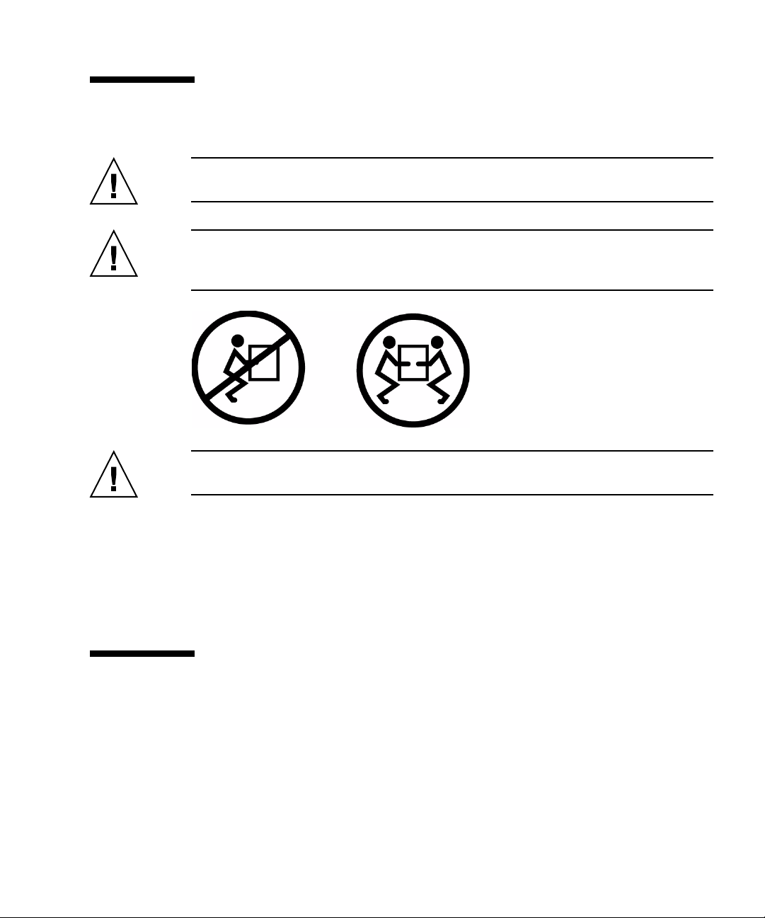
Task Warning
Installation Damage
Deploy the antitilt feature on the rack before beginning an installation.
The SPARC Enterprise T5220 server weighs approximately 55 lb (25 kg).
Two people are required to lift and mount the system into a rack
enclosure when using the procedures in this book.
When completing a two-person procedure, always communicate your
intentions clearly before, during, and after each step to minimize
confusion.
The weight of the server on extended slide rails can be enough to
overturn an equipment rack.
Caution – This indicates that hazardous voltages are present. To reduce the risk of
electric shock and danger to personal health, follow the instructions.
Task Warning
Installation Electric shock
There is a potential for electric shock if the server and related equipment
are not properly grounded.
xvi SPARC Enterprise T5120 and T5220 Servers Installation Guide • July 2009
Product Handling
Maintenance
Warning – Certain tasks in this manual should only be performed by a certified
service engineer. User must not perform these tasks. Incorrect operation of these
tasks may cause electric shock, injury, or fire.
■ Installation and reinstallation of all components, and initial settings
■ Removal of front, rear, or side covers
■ Mounting/de-mounting of optional internal devices
■ Plugging or unplugging of external interface cards
■ Maintenance and inspections (repairing, and regular diagnosis and maintenance)
Caution – The following tasks regarding this product and the optional products
provided from Fujitsu should only be performed by a certified service engineer.
Users must not perform these tasks. Incorrect operation of these tasks may cause
malfunction.
■ Unpacking optional adapters and such packages delivered to the users
■ Plugging or unplugging of external interface cards
Remodeling/Rebuilding
Caution – Do not make mechanical or electrical modifications to the equipment.
Using this product after modifying or reproducing by overhaul may cause
unexpected injury or damage to the property of the user or bystanders.
Preface xvii
Alert Label
The following is a label attached to this product:
■ Never peel off the label.
■ The following label provides information to the users of this product.
xviii SPARC Enterprise T5120 and T5220 Servers Installation Guide • July 2009

Fujitsu Welcomes Your Comments
If you have any comments or requests regarding this document, or if you find any
unclear statements in the document, please state your points specifically on the form
at the following URL.
For Users in U.S.A., Canada, and Mexico:
(https://download.computers.us.fujitsu.com/)
For Users in Other Countries:
(http://www.fujitsu.com/global/contact/computing/sparce_index.ht
ml)
Preface xix

xx SPARC Enterprise T5120 and T5220 Servers Installation Guide • July 2009

Preparing for Installation
This chapter provides background information about the installation procedures for
both servers. This chapter contains these topics:
■ “Server Handling Precautions” on page 3
■ “Input Power Information and Precautions” on page 3
■ “Tools and Equipment Needed” on page 4
■ “Optional Component Installation” on page 5
■ “ESD Precautions” on page 5
■ “Installation Overview” on page 6
■ “Preparing for Installation” on page 8
■ “Installing the Hardware” on page 8
■ “Configuring the Service Processor” on page 9
■ “Configuring the Host Software” on page 10
■ “Cabling Notes for Both Servers” on page 10
■ “Port, Connector, and LED Locations for Both Servers” on page 12
■ “Slide Rail Assembly Notes for Both Servers” on page 15
■ “Cable Management Notes for Both Servers” on page 18
Server Overview
The SPARC Enterprise T5120 server is a 1 rack unit (1U) server. The SPARC
Enterprise T5220 server is a 2 rack unit (2U) server.
1
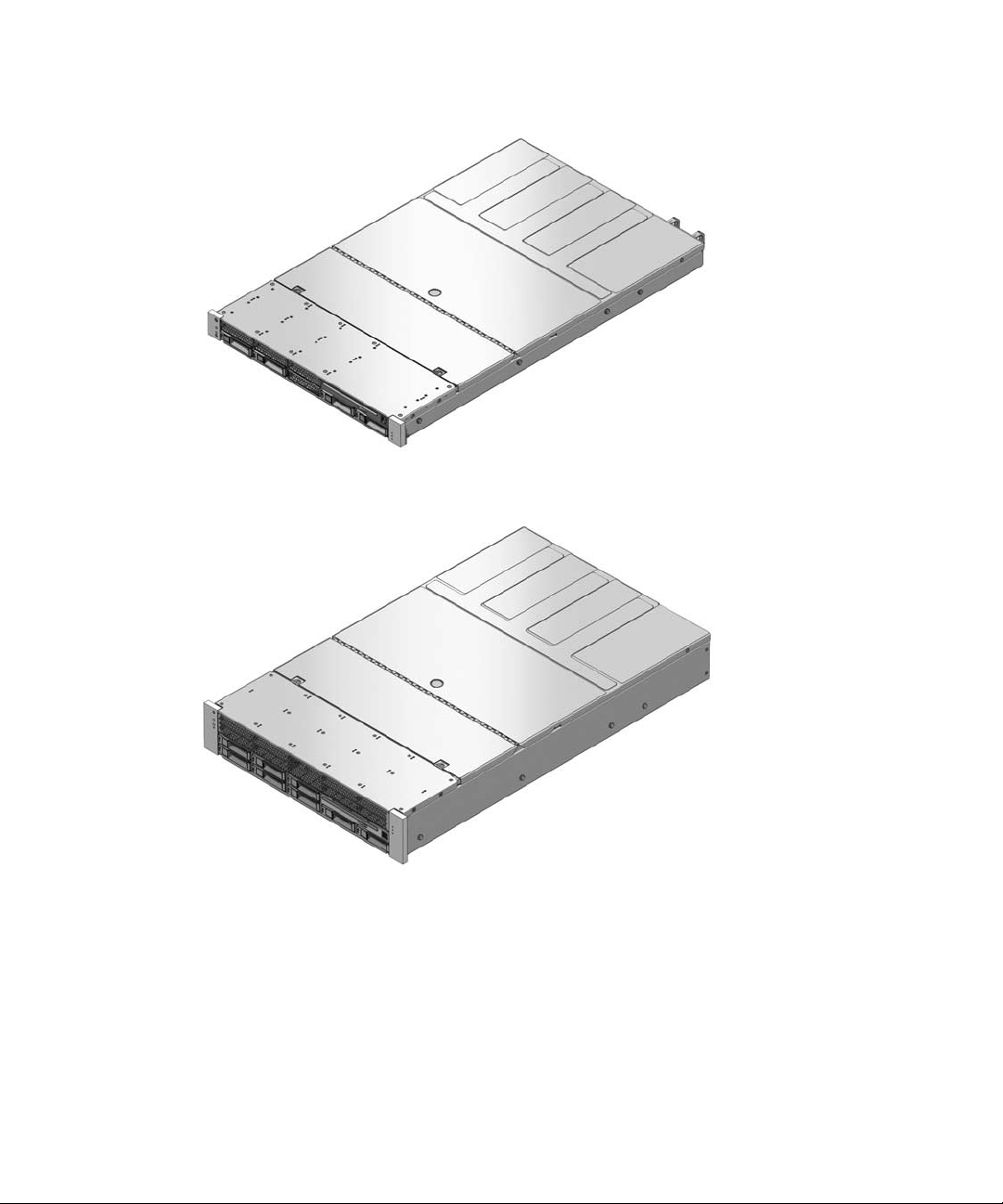
FIGURE: SPARC Enterprise T5120 Server
FIGURE: SPARC Enterprise T5220 Server
Related Information
■ SPARC Enterprise T5120 and T5220 Servers Getting Started Guide
■ SPARC Enterprise T5120 and T5220 Servers Getting Started Guide (DC)
2 SPARC Enterprise T5120 and T5220 Servers Installation Guide • July 2009
Server Handling Precautions
Caution – Deploy the antitilt bar on the equipment rack before beginning an
installation.
Caution – The SPARC Enterprise T5220 server weighs approximately 55 lb (25. kg).
Two people are required to lift and mount this 2U server into a rack enclosure when
using the procedures in this document.
Caution – When completing a two-person procedure, always communicate your
intentions clearly before, during, and after each step to minimize confusion.
Related Information
■ “Input Power Information and Precautions” on page 3
■ SPARC Enterprise T5120 and T5220 Servers Getting Started Guide
■ SPARC Enterprise T5120 and T5220 Servers Getting Started Guide (DC)
Input Power Information and Precautions
The SPARC Enterprise T5120 and T5220 servers are available in the following input
power configurations:
■ Two redundant, hot-swappable AC power supplies
■ Two redundant, DC power supplies
Preparing for Installation 3

Note – Safety agency requirements prohibit manufacturers from changing a product
from AC input to DC input or from DC input to AC input after the product has been
removed from the agency approved manufacturing site.
Note – The DC version of the server must be installed in a restricted-access location.
According to the intent of the National Electrical Code, a restricted-access location is
an area intended for qualified or trained personnel only and has access controlled by
a locking mechanism, such as a key lock or an access card system.
When each power supply is connected to a separate power source, the server
continues to operating under the following fault conditions:
■ A power source failure that removes input power from one of the power supplies.
■ Failure of one of the power supplies.
■ Service actions which require removal of one of the power supplies.
Refer to the SPARC Enterprise T5120 and T5220 Servers Site Planning Guide for input
power specifications.
Note – Input AC/DC power cables: To avoid missing initialization messages, do not
attach power cables to the power supplies until you have finished connecting the
data cables, and have connected the server to a serial terminal or a terminal emulator
(PC or workstation). The server goes into Standby mode and the ILOM service
processor initializes as soon as the input power cables are connected to the power
source.
Related Information
■ SPARC Enterprise T5120 and T5220 Servers Site Planning Guide
Tools and Equipment Needed
To install the system, you must have the following tools:
■ No. 2 Phillips screwdriver
■ ESD mat and grounding strap
In addition, you must provide a system console device, such as one of the following:
■ ASCII terminal
4 SPARC Enterprise T5120 and T5220 Servers Installation Guide • July 2009

■ Workstation
■ Terminal server
■ Patch panel connected to a terminal server
Related Information
■ “Optional Component Installation” on page 5
Optional Component Installation
The standard components of the server are installed at the factory. However, if you
ordered options such as additional memory or PCI cards, these options will be
shipped separately. If possible, install these components prior to installing the server
in a rack.
If you ordered any options that are not factory-installed, see the SPARC Enterprise
T5120 and T5220 Servers Service Manual for installation instructions.
Note – The list of optional components can be updated without notice. See the
product web pages for the most current list of components supported in the server.
Related Information
■ SPARC Enterprise T5120 and T5220 Servers Getting Started Guide
■ SPARC Enterprise T5120 and T5220 Servers Getting Started Guide (DC)
■ SPARC Enterprise T5120 and T5220 Servers Service Manual
ESD Precautions
Electronic equipment is susceptible to damage by static electricity. Use a grounded
antistatic wriststrap, footstrap, or equivalent safety equipment to prevent
electrostatic damage (ESD) when you install or service the servers.
Preparing for Installation 5

Caution – To protect electronic components from electrostatic damage, which can
permanently disable the system or require repair by service technicians, place
components on an antistatic surface, such as an antistatic discharge mat, an antistatic
bag, or a disposable antistatic mat. Wear an antistatic grounding strap connected to a
metal surface on the chassis when you work on system components.
Related Information
■ “Installation Overview” on page 6
Installation Overview
This installation guide provides procedures that are to be performed in the following
order.
6 SPARC Enterprise T5120 and T5220 Servers Installation Guide • July 2009
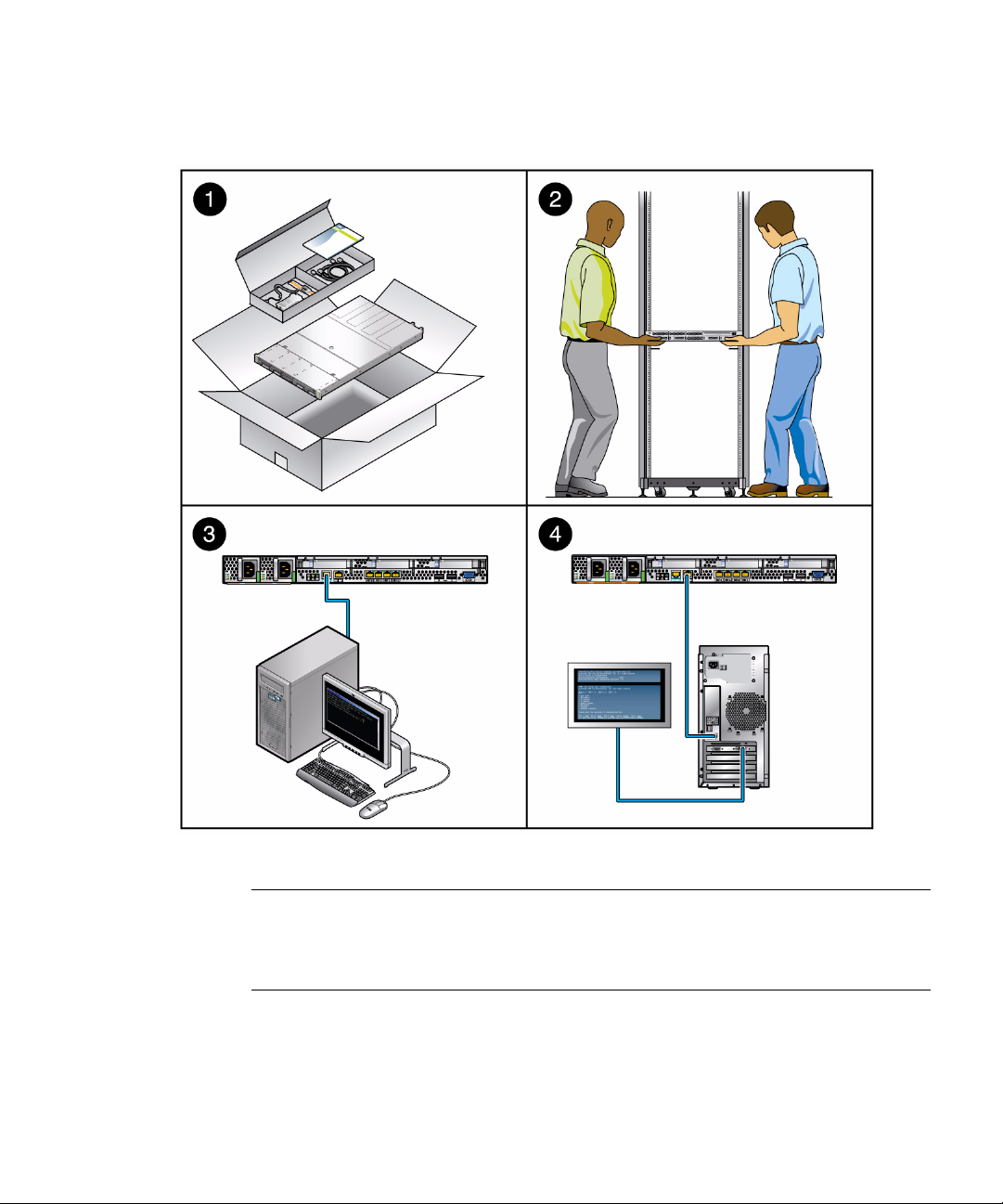
FIGURE: Installation Overview
Figure Leg end
1 Preparing for installation
2 Installing the hardware
3 Configuring the service processor
4 Configuring the host software
Preparing for Installation 7

Preparing for Installation
1. Verify that you have received all of the components that ship with your server.
2. Gather configuration information for your system. See your system administrator
for specific details, including these parameters:
■ Netmask
■ IP address for the service processor
■ Gateway IP address
3. Install any optional components shipped with your system. If you have purchased
other optional components such as additional memory, install them prior to
mounting the server in a rack.
Related Information
■ “Optional Component Installation” on page 5
Installing the Hardware
1. Mount the server into a rack or cabinet. See “Installing the Servers in a Rack” on
page 19 for both the 1U and 2U servers. Or, if you ordered the express rail
rackmounting kit, which has the same rack rail assemblies for both servers, see
“Installing the Servers in a Rack With Express Rails” on page 76.
Note – In the rest of this manual, the term rack means either an open rack or a closed
cabinet.
2. Connect the server to a serial terminal or a terminal emulator (PC or workstation)
to display system messages. See “Powering On the System for the First Time” on
page 43.
8 SPARC Enterprise T5120 and T5220 Servers Installation Guide • July 2009
 Loading...