

Fujitsu SPARC Enterprise M3000, SPARC Enterprise M8000, SPARC Enterprise M5000, SPARC Enterprise M4000, SPARC Enterprise M9000 User Manual
Page 1

SPARC Enterprise
M3000/M4000/M5000/M8000/M9000
Servers
XSCF User's Guide
Part No.: E25381-01,
Manual Code: C120-E332-11EN
January 2012
Page 2

Copyright © 2007, 2012, Fujitsu Limited. All rights reserved.
Oracle and/or its affiliates provided technical input and review on portions of this material.
Oracle and/or its affiliates and Fujitsu Limited each own or control intellectual property rights relating to products and technolog y described in this
document, and such products, technology and this document are protected by copyright laws, patents, and other intellectual property laws and
international treaties.
This document and the product and technology to which it pertains are distributed under licenses restricting their use, copying, distribution, and
decompilation. No part of such product or technology, or of this document, may be reproduced in any form by any means without prior written
authorization of Oracle and/or its affiliates and Fujitsu Limited, and their applicable licensors, if any. The furnishings of this document to you does not
give you any rights or licenses, express or implied, with respect to the product or technology to which it pertains, and this document does not contain or
represent any commitment of any kind on the part of Oracle or Fujitsu Limited, or any affiliate of either of them.
This document and the product and technology described in this document may incorporate third-party intellectual property copyrighted by and/or
licensed from the suppliers to Oracle and/or its affiliates and Fujitsu Limited, including software and font technology.
Per the terms of the GPL or LGPL, a copy of the source code governed by the GPL or LGPL, as applicab le, is ava ilable upon request by the End User. Please
contact Oracle and/or its affiliates or Fujitsu Limited.
This distribution may include materials developed by third parties.
Parts of the product may be derived from Berkeley BSD systems, licensed from the University of California. UNIX is a registered trademark in the U.S. and
in other countries, exclusively licensed through X/Open Company, Ltd.
Oracle and Java are registered trademarks of Oracle and/or its affiliates. Fujitsu and the Fujitsu logo are registered trademarks of Fujitsu Limited.
All SPARC trademarks are used under license and are registered trademarks of SPARC International, Inc. in the U.S. and other countries. Products bearing
SPARC trademarks are based upon architectures developed by Oracle and/or its affiliates. SPARC64 is a trademark of SPARC International, Inc., used
under license by Fujitsu Microelectronics, Inc. and Fujitsu Limited. Other names may be trademarks of their respective owners.
United States Government Rights - Commercial use. U.S. Government users are subject to the standard government user license agreements of Oracle
and/or its affiliates and Fujitsu Limited and the applicable provisions of the FAR and its supplements.
Disclaimer: The only warranties granted by Oracle and Fujitsu Limited, and/or any affiliate of either of them in connection with this document or any
product or technology described herein are those expressly set forth in the license agreement pursuant to which the product or technology is provided.
EXCEPT AS EXPRESSLY SET FORTH IN SUCH AGREEMENT, ORACLE OR FUJITSU LIMITED, AND/OR THEIR AFFILIATES MAKE NO
REPRESENTATIONS OR WARRANTIES OF ANY KIND (EXPRESS OR IMPLIED) REGARDING SUCH PRODUCT OR TECHNOLOGY OR THIS
DOCUMENT, WHICH ARE ALL PROVIDED AS IS, AND ALL EXPRESS OR IMPLIED CONDITIONS, REPRESENTATIONS AND WARRANTIES,
INCLUDING WITHOUT LIMITATION ANY IMPLIED WARRANTY OF MERCHANTABILITY, FITNESS FOR A PARTICULAR PURPOSE OR NONINFRINGEMENT, ARE DISCLAIMED, EXCEPT TO THE EXTENT THAT SUCH DISCLAIMERS ARE HELD TO BE LEGALLY INVALID. Unless
otherwise expressly set forth in such agreement, to the extent allowed by applicable law, in no event shall Oracle or Fujitsu Limited, and/or any of their
affiliates have any liability to any third party under any legal theory for any loss of revenues or profits, loss of use or data, or business interruptions, or for
any indirect, special, incidental or consequential damages, even if advised of the possibility of such damages.
DOCUMENTATION IS PROVIDED “AS IS” AND ALL EXPRESS OR IMPLIED CONDITIONS, REPRESENTATIONS AND WARRANTIES,
INCLUDING ANY IMPLIED WARRANTY OF MERCHANTABILITY, FITNESS FOR A PARTICULAR PURPOSE OR NON-INFRINGEMENT, ARE
DISCLAIMED, EXCEPT TO THE EXTENT THAT SUCH DISCLAIMERS ARE HELD TO BE LEGALLY INVALID.
Please
Recycle
Page 3

Copyright © 2007, 2012, Fujitsu Limited. Tous droits réservés.
Oracle et/ou ses sociétés affiliées ont fourni et vérifié des donn ées techniq ues de certaines parties de ce composant.
Oracle et/ou ses sociétés affiliées et Fujitsu Limited détiennent et contrôlent chacune des droits de propriété intellectuelle relatifs aux produits et
technologies décrits dans ce document. De même, ces produits, technologies et ce document sont protégés par des lois sur le copyright, des brevets,
d’autres lois sur la propriété intellectuelle et des traités internationaux.
Ce document, le produit et les technologies afférents sont exclusivement distribués avec des licences qui en restreignent l’utilisation, la copie, la
distribution et la décompilation. Aucune partie de ce produit, de ces technologies ou de ce document ne peut être reproduite sous quelque forme que ce
soit, par quelque moyen que ce soit, sans l’autorisation écrite préalable d’Oracle et/ou ses sociétés affiliées et de Fujitsu Limited, et de leurs éventuels
bailleurs de licence. Ce document, bien qu’il vous ait été fourni, ne vous confère aucun droit et aucune licence, expresses ou tacites, concernant le produit
ou la technologie auxquels il se rapporte. Par ailleurs, il ne contient ni ne représente aucun engagement, de quelque type que ce soit, de la part d’Oracle ou
de Fujitsu Limited, ou des sociétés affiliées de l’une ou l’autre entité.
Ce document, ainsi que les produits et technologies qu’il décrit, peuvent inclure des droits de propriété intellectuelle de parties tierces protégés par
copyright et/ou cédés sous licence par des fournisseurs à Oracle et/ou ses sociétés affiliées et Fujitsu Limited, y compris des logiciels et des technologies
relatives aux polices de caractères.
Conformément aux conditions de la licence GPL ou LGPL, une copie du code source régi par la licence GPL ou LGPL, selon le cas, est disponible sur
demande par l’Utilisateur final. Veuillez contacter Oracle et/ou ses sociétés affiliées ou Fujitsu Limited.
Cette distribution peut comprendre des composants développés par des parties tierces.
Des parties de ce produit peuvent être dérivées des systèmes Berkeley BSD, distribués sous licence par l’Université de Californie. UNIX est une marque
déposée aux États-Unis et dans d’autres pays, distribuée exclusivement sous licence par X/Open Company, Ltd.
Oracle et Java sont des marques déposées d’Oracle Corporation et/ou de ses sociétés affiliées. Fujitsu et le logo Fujitsu sont des marques déposées de
Fujitsu Limited.
Toutes les marques SPARC sont utilisées sous licence et sont des marques déposées de SPARC International, Inc., aux États-Unis et dans d’autres pays. Les
produits portant la marque SPARC reposent sur des architectures développées par Oracle et/ou ses sociétés affiliées. SPARC64 est une marque de SPARC
International, Inc., utilisée sous licence par Fujitsu Microelectronics, Inc. et Fujitsu Limited. Tout autre nom mentionné peut corresp ondre à des marq ues
appartenant à d’autres propriétaires.
United States Government Rights - Commercial use. U.S. Government users are subject to the standard government user license agreements of Oracle
and/or its affiliates and Fujitsu Limited and the applicable provisions of the FAR and its supplements.
Avis de non-responsabilité : les seules garanties octroyées par Oracle et Fujitsu Limited et/ou toute société affiliée de l’une ou l’autre entité en rapport avec
ce document ou tout produit ou toute technologie décrits dans les présentes correspondent aux garanties expressément stipulées dans le contrat de licence
régissant le produit ou la technologie fournis. SAUF MENTION CONTRAIRE EXPRESSÉMENT STIPULÉE DANS CE CONTRAT, ORACLE OU FUJITSU
LIMITED ET LES SOCIÉTÉS AFFILIÉES À L’UNE OU L’AUTRE ENTITÉ REJETTENT TOUTE REPRÉSENTATION OU TOUTE GARANTIE, QUELLE
QU’EN SOIT LA NATURE (EXPRESSE OU IMPLICITE) CONCERNANT CE PRODUIT, CETTE TECHNOLOGIE OU CE DOCUMENT, LESQUELS
SONT FOURNIS EN L’ÉTAT. EN OUTRE, TOUTE S LES CONDITIONS, REPRÉSENTATIONS ET GARANTIES EXPRESSES OU TACITES, Y COMPRIS
NOTAMMENT TOUTE GARANTIE IMPLICITE RELATIVE À LA QUALITÉ MARCHANDE, À L’APTITUDE À UNE UT ILISATION PARTICULIÈRE
OU À L’ABSENCE DE CONTREFAÇON, SONT EXCLUES, DANS LA MESU RE AUTORISÉE PAR LA LOI APPLICABLE. Sauf mention contraire
expressément stipulée dans ce contrat, dans la mesure autorisée par la loi applicable, en aucun cas Oracle ou Fujitsu Limited et/ou l’une ou l’autre de leurs
sociétés affiliées ne sauraient être tenues responsables envers une quelconque partie tierce, sous quelque théorie juridique que ce soit, de tout manque à
gagner ou de perte de profit, de problèmes d’utilisation ou de perte de données, ou d’interruptions d’activités, ou de tout dommage indirect, spécial,
secondaire ou consécutif, même si ces entités ont été préalablement informées d’une telle éventualité.
LA DOCUMENTATION EST FOURNIE « EN L’ÉTAT » ET TOUTE AUTRE CONDITION, DÉCLARATION ET GARANTIE, EXPRESSE OU TACITE, EST
FORMELLEMENT EXCLUE, DANS LA MESURE AUTORISÉE PAR LA LOI EN VIGUEUR, Y COMPRIS NOTAMMENT TOUTE GARANTIE
IMPLICITE RELATIVE À LA QUALITÉ MARCHANDE, À L’APTITUDE À UNE UTILISATION PARTICULIÈRE OU À L’ABSENCE DE
CONTREFAÇON.
Page 4

Page 5

Contents
Preface xiii
1. XSCF Overview 1–1
1.1 XSCF Features 1–1
1.2 XSCF Functions 1–9
1.2.1 Major Differences Among the Server Models 1–14
1.3 Types of Connection to XSCF 1–14
1.3.1 Examples of LAN Connection Operations 1–16
1.3.2 NTP Configuration and Time Synchronization 1–20
1.3.3 The CD-RW/DVD-RW Drive Unit and Tape Drive Unit 1–20
1.4 XSCF User Interfaces 1–21
1.4.1 User Accounts and User Privileges 1–23
2. Setting Up XSCF 2–1
2.1 XSCF Setup Summary 2–1
2.1.1 Setup Summary by the XSCF Shell 2–2
2.1.2 Setup Summary Using the XSCF Web 2–12
2.2 Specifying the XSCF Settings 2–15
2.2.1 Network Configuration 2–16
2.2.2 User Account Administration 2–35
v
Page 6

2.2.3 LDAP Administration 2–43
2.2.4 Active Directory Administration 2–48
2.2.5 LDAP/SSL Administration 2–70
2.2.6 Time Administration 2–90
2.2.7 SSH/Telnet Administration 2–101
2.2.8 Https Administration 2–109
2.2.9 Audit Administration 2–116
2.2.10 Log Archiving Administration 2–123
2.2.11 SNMP Administration 2–128
2.2.12 Mail Administration 2–139
2.2.13 Domain Configuration 2–142
2.2.14 System Board Configuration 2–170
2.2.15 Domain Mode Configuration 2–173
2.2.16 Locale Administration 2–184
2.2.17 Altitude Administration 2–185
2.2.18 DVD Drive/Tape Drive Unit Administration 2–186
2.3 Save and Restore XSCF Configuration Information 2–189
3. Connecting to the XSCF and the Server 3–1
3.1 Connect Terminals to the XSCF 3–1
3.1.1 Terminal Operating Modes for Connection to XSCF 3–2
3.1.2 Port and Terminal Types Connected to the XSCF 3–2
3.1.3 About the XSCF-LAN/the DSCP Link Port Number and the
Function and the Firewall 3–5
3.1.4 Connecting to XSCF via the Serial Port 3–7
3.1.5 Connecting to XSCF Using SSH via the LAN Port 3–8
3.1.6 Connecting to XSCF Using Telnet via the LAN Port 3–9
3.1.7 Switching Between the XSCF Shell and the Domain Console 3–10
3.2 Types of XSCF Connections 3–11
vi SPARC Enterprise Mx000 Servers XSCF User’s Guide • January 2012
Page 7

3.2.1 Connecting XSCF via the XSCF-LAN Port Or the Serial Port 3–12
3.2.2 XSCF-LAN and Serial Connection Purposes 3–15
4. Operation of the Server 4–1
4.1 Display Server Hardware Environment 4–1
4.1.1 Displaying System Information 4–2
4.1.2 Display Server Configuration/Status Information 4–6
4.2 Display Domain Information 4–9
4.2.1 Domain Information 4–10
4.3 Adding or Removing Domains 4–11
4.4 Server and Domain Power Operations 4–12
4.4.1 System Power On 4–13
4.4.2 System Power Off 4–14
4.4.3 Domain Power On 4–15
4.4.4 Domain Power Off 4–16
4.4.5 Sending a Domain Panic Request 4–17
4.4.6 Domain Reset 4–18
4.4.7 Sending a Break Signal to a Domain 4–19
4.4.8 Air-Conditioning Wait Time Administration 4–20
4.4.9 Warm-Up Time Administration 4–21
4.4.10 Shutdown Wait Time Administration 4–22
4.4.11 Dual Power Feed Administration 4–22
4.5 Identifying the Location of the System 4–24
4.6 Managing Fault Degradation 4–24
4.6.1 Displaying the Degraded Component 4–24
4.6.2 Clearing the Fault/Degradation Information 4–25
4.7 Changing the Time 4–26
4.8 Switching the XSCF Unit 4–26
Contents vii
Page 8

4.9 Displaying State of an External I/O Expansion Unit and Administration
4–27
4.10 Restore Factory Settings of the Server or XSCF Unit 4–32
5. Overview of the XSCF Shell 5–1
5.1 Overview of the XSCF Command Shell 5–1
5.2 Login to XSCF Shell 5–7
5.2.1 Before Logging In 5–7
5.2.2 Operation From a Terminal Connected to the Serial Port 5–8
5.2.3 Operation for Connecting Via the XSCF-LAN (SSH) 5–8
5.2.4 Operation For Connecting Via the XSCF-LAN (Telnet) 5–9
5.3 View Server Status and Control Commands 5–10
5.4 Server Configuration Information Commands 5–12
5.5 Domain Control and Maintenance Commands 5–13
5.6 View and Archive the XSCF Logs 5–15
5.7 User Management and Security Commands 5–16
5.8 Use the XSCF Other Commands 5–17
5.9 View XSCF Shell Error Messages 5–18
6. XSCF Mail Function 6–1
6.1 Overview of XSCF Mail Function 6–1
6.2 Setting Up the Mail Function 6–3
6.3 Contents of Parts Fault Notification 6–5
6.4 Test Mail 6–6
7. XSCF SNMP Agent Function 7–1
7.1 Overview of the XSCF SNMP Agent 7–1
7.2 MIB Definition File 7–3
7.3 About Trap 7–5
7.4 Setting Up the XSCF SNMP Agent Function 7–8
viii SPARC Enterprise Mx000 Servers XSCF User’s Guide • January 2012
Page 9

8. Upgrade of XSCF Firmware and Maintenance 8–1
8.1 Update the XSCF Firmware 8–1
8.1.1 Firmware Update Overview 8–1
8.1.2 Firmware Update Conditions and Environment 8–3
8.1.3 Method of Delivering Firmware 8–4
8.1.4 Method of Checking the Firmware Version 8–5
8.1.5 Three Steps of the Firmware Update 8–6
8.1.6 Features of XSCF Firmware Update 8–7
8.1.7 Firmware Update Types and Timing 8–7
8.1.8 Firmware Update for Redundant XSCF Units 8–9
8.1.9 Ensuring Proper Operation After a Firmware Update 8–9
8.1.10 Firmware Update Procedure 8–10
8.1.11 If an Error Occurs During XSCF Firmware Update 8–21
8.1.12 Frequently Asked Questions 8–21
8.2 Collecting XSCF Logs 8–22
8.2.1 Log Types and Reference Commands 8–22
8.2.2 Method of Collecting the Log Information 8–25
9. How to Use the XSCF Web 9–1
9.1 Overview of the XSCF Web 9–1
9.2 Start the XSCF Web 9–5
9.2.1 Prerequisites 9–6
9.2.2 Supported Browsers 9–6
9.2.3 Functions to be Enabled on the Browser 9–6
9.2.4 Specifying the URL 9–7
9.3 Logging In and Out of the XSCF Web 9–7
9.3.1 Logging in to XSCF 9–7
9.3.2 Access Status Monitoring 9–7
9.3.3 Logging Out From XSCF 9–8
Contents ix
Page 10

9.4 XSCF Web Pages 9–9
9.5 XSCF Web Error Messages 9–30
A. Warning and Information Messages A–1
A.1 Message Types A–1
A.2 Messages in Each Function A–3
B. XSCF Log Information B–1
B.1 XSCF Error Log B–1
B.2 Power Log B–5
B.3 Event Log B–7
B.4 Using the showlogs Command to Display Other Logs B–8
B.4.1 Monitor Message Log B–8
B.4.2 Temperature and Humidity History Log B–8
B.4.3 Console Log B–9
B.4.4 Panic Log B–9
B.4.5 IPL Log B–9
B.5 Audit Log B–10
B.6 Active Directory Log B–12
B.7 LDAP/SSL Log B–12
B.8 COD activation Log B–13
C. XSCF MIB C–1
C.1 MIB Object Identifiers C–1
C.2 Standard MIB C–3
C.3 Extended MIB C–3
C.4 Trap C–5
D. Troubleshooting D–1
D.1 Troubleshooting XSCF and FAQ D–1
x SPARC Enterprise Mx000 Servers XSCF User’s Guide • January 2012
Page 11

D.2 Troubleshooting the Server While XSCF Is Being Used D–7
E. Software License Conditions E–1
Index Index–1
Contents xi
Page 12

xii SPARC Enterprise Mx000 Servers XSCF User’s Guide • January 2012
Page 13

Preface
This manual describes the system monitor and control facility, known as eXtended
System Control Facility (XSCF), which is used to control, monitor, operate, and
service SPARC Enterprise M3000/M4000/M5000/M8000/M9000 servers and
domains from Oracle and Fujitsu.
XSCF may also be referred to as the System Control Facility (SCF). Unless otherwise
stated in this manual, the SPARC Enterprise system is described as “the server” or
“the system”.
Some references to server names and document names are abbreviated for
readability. For example, if you see a reference to the M9000 server, note that the full
product name is the SPARC Enterprise M9000 server. And if you see a reference to
the XSCF Reference Manual, note that the full document name is the SPARC Enterprise
M3000/M4000/M5000/M8000/M9000 Servers XSCF Reference Manual.
Before reading this document, you should read the overview guide for your server
and the SPARC Enterprise M3000/M4000/M5000/M8000/M9000 Servers Administration
Guide.
At publication of this document, servers described herein were shipping with XCP
1110 firmware installed. That might no longer be the latest available version, or the
version now installed. Always see the Product Notes that apply to the firmware on
your server, and those that apply to the latest firmware release.
This chapter includes the following sections:
■ “Audience” on page xiv
■ “Related Documentation” on page xiv
■ “Text Conventions” on page xvi
■ “Syntax of the Command-Line Interface (CLI)” on page xvii
■ “Documentation Feedback” on page xvii
Preface xiii
Page 14

Audience
This guide is written for experienced system administrators with working
knowledge of computer networks and advanced knowledge of the Oracle Solaris
Operating System (Oracle Solaris OS).
Related Documentation
All documents for your server are available online at the following locations:
Documentation Link
Sun Oracle software-related manuals
(Oracle Solaris OS, and so on)
Fujitsu documents
Oracle M-series server documents http://www.oracle.com/technetwork/documentation/s
http://www.oracle.com/documentation
http://www.fujitsu.com/sparcenterprise/manual/
parc-mseries-servers-252709.html
The following table lists titles of related documents.
Related SPARC Enterprise M3000/M4000/M5000/M8000/M9000 Servers Documents
SPARC Enterprise M3000 Server Site Planning Guide
SPARC Enterprise M4000/M5000 Servers Site Planning Guide
SPARC Enterprise M8000/M9000 Servers Site Planning Guide
SPARC Enterprise Equipment Rack Mounting Guide
SPARC Enterprise M3000 Server Getting Started Guide
SPARC Enterprise M4000/M5000 Servers Getting Started Guide
SPARC Enterprise M8000/M9000 Servers Getting Started Guide
SPARC Enterprise M3000 Server Overview Guide
SPARC Enterprise M4000/M5000 Servers Overview Guide
SPARC Enterprise M8000/M9000 Servers Overview Guide
SPARC Enterprise M3000/M4000/M5000/M8000/M9000 Servers Important Legal and Safety Information
*
*
*
*
xiv SPARC Enterprise Mx000 Servers XSCF User’s Guide • January 2012
Page 15

Related SPARC Enterprise M3000/M4000/M5000/M8000/M9000 Servers Documents
SPARC Enterprise M3000 Server Safety and Compliance Guide
SPARC Enterprise M4000/M5000 Servers Safety and Compliance Guide
SPARC Enterprise M8000/M9000 Servers Safety and Compliance Guide
External I/O Expansion Unit Safety and Compliance Guide
SPARC Enterprise M4000 Server Unpacking Guide
SPARC Enterprise M5000 Server Unpacking Guide
SPARC Enterprise M8000/M9000 Servers Unpacking Guide
*
*
*
SPARC Enterprise M3000 Server Installation Guide
SPARC Enterprise M4000/M5000 Servers Installation Guide
SPARC Enterprise M8000/M9000 Servers Installation Guide
SPARC Enterprise M3000 Server Service Manual
SPARC Enterprise M4000/M5000 Servers Service Manual
SPARC Enterprise M8000/M9000 Servers Service Manual
External I/O Expansion Unit Installation and Service Manual
SPARC Enterprise M3000/M4000/M5000/M8000/M9000 Servers Administration Guide
SPARC Enterprise M3000/M4000/M5000/M8000/M9000 Servers XSCF User’s Guide
SPARC Enterprise M3000/M4000/M5000/M8000/M9000 Servers XSCF Reference Manual
SPARC Enterprise M4000/M5000/M8000/M9000 Servers Dynamic Reconfiguration (DR) User’s Guide
SPARC Enterprise M4000/M5000/M8000/M9000 Servers Capacity on Demand (COD) User’s Guide
SPARC Enterprise M3000/M4000/M5000/M8000/M9000 Servers Product Notes
†
SPARC Enterprise M3000 Server Product Notes
SPARC Enterprise M4000/M5000 Servers Product Notes
SPARC Enterprise M8000/M9000 Servers Product Notes
External I/O Expansion Unit Product Notes
SPARC Enterprise M3000/M4000/M5000/M8000/M9000 Servers Glossary
* This is a printed document.
† Beginning with the XCP 1100 release.
Preface xv
Page 16

Text Conventions
This manual uses the following fonts and symbols to express specific types of
information.
Font/symbol Meaning Example
AaBbCc123 What you type, when contrasted
with on-screen computer output.
This font represents the example of
command input in the frame.
AaBbCc123 The names of commands, files, and
directories; on-screen computer
output.
This font represents the example of
command output in the frame.
Italic Indicates the name of a reference
manual, a variable, or userreplaceable text.
" " Indicates names of chapters,
sections, items, buttons, or menus.
XSCF> adduser jsmith
XSCF> showuser -p
User Name: jsmith
Privileges: useradm
auditadm
See the SPARC Enterprise
M3000/M4000/M5000/M8000/M9
000 Servers XSCF User’s Guide.
See Chapter 2, "System Features"
xvi SPARC Enterprise Mx000 Servers XSCF User’s Guide • January 2012
Page 17

Syntax of the Command-Line Interface (CLI)
The command syntax is as follows:
■ A variable that requires input of a value must be put in Italics.
■ An optional element must be enclosed in [].
■ A group of options for an optional keyword must be enclosed in [] and delimited
by |.
Documentation Feedback
If you have any comments or requests regarding this document, go to the following
websites:
■ For Oracle users:
http://www.oracle.com/goto/docfeedback
Include the title and part number of your document with your feedback:
SPARC Enterprise M3000/M4000/M5000/M8000/M9000 Servers XSCF User’s Guide,
part number E25381-01
■ For Fujitsu users:
http://www.fujitsu.com/global/contact/computing/sparce_index.html
Preface xvii
Page 18

xviii SPARC Enterprise Mx000 Servers XSCF User’s Guide • January 2012
Page 19

CHAPTER
1
XSCF Overview
This chapter provides an overview of the system monitoring and control facility
(eXtended System Control Facility, or XSCF).
1.1 XSCF Features
The XSCF firmware is a system monitoring and control facility consisting of a
dedicated processor (Note 1) that is independent from the system processor. While
input power is supplied to the server, the XSCF constantly monitors the server even
if no domain is active. The XSCF provides an interface between the user and the
server.
The XSCF is the firmware running on the Service Processor in the server. In the rest
of this chapter, although XSCF firmware programs are called XSCF firmware, or
XSCF, they all have the same meaning. The board with the installed XSCF firmware
is called the XSCFU (also referred to as the "XSCF Unit") or Service Processor.
The XSCF uses different functions to achieve high system availability. The XSCF
firmware is a single centralized point for the management of hardware
configuration, control of hardware monitoring, cooling system (fan units), domain
status monitoring, power on and power off of peripheral devices (Note 2), and error
monitoring. The XSCF centrally controls and monitors the server. The XSCF also has
a partitioning function to configure and control domains, and it has a function to
monitor the server through an Ethernet connection so that the user can control the
server remotely. Another function is to report failure information to the system
administrator and a remote control input/output function.
In the SPARC Enterprise M3000 server (the M3000 server; the entry-level server) and
the SPARC Enterprise M4000/M5000 (the M4000/M5000 servers; the midrange
servers), a single XSCF Unit is installed in the server. In the SPARC Enterprise
M8000/M9000 servers (the M8000/M9000 servers; the high-end servers), two XSCF
Units are installed in the server and they are duplicated. Also, in the M3000 server,
1-1
Page 20

the XSCF Unit is fixed to the Motherboard Unit (MBU). For details of the server
differences, see Section 1.2.1, “Major Differences Among the Server Models” on
page 1-14.
Note – (1) Processors on server boards are called CPUs.
Note – (2) Only the system model with a special interface can power on and off the
peripheral devices. (See Remote Cabinet Interface (RCI) in External Interfaces.)
Redundant XSCFs (High-End Servers Only)
The high-end servers use a redundant configuration of XSCF Units, thereby
providing high system reliability. The XSCF that controls the server is called the
Active XSCF or Active XSCF Unit, while the other XSCF acts as a backup and is
called the Standby XSCF or Standby XSCF Unit. The Active XSCF and the Standby
XSCF monitor each other, and if an error is detected, they determine when a failover
switching to Active or Standby should be performed.
External Interfaces
The following connectors (ports) and LEDs act as the external interface of the XSCF
Unit. The user, system administrator, and field engineer (FE) can use these ports for
server monitoring and XSCF firmware operations:
■ One Serial port that can be used for the command-line interface (CLI) (Note 1)
■ Two Ethernet ports (XSCF-LAN ports) (10Base-T / 100Base-T (TX))
CLI and the browser user interface (BUI) can be used with these ports for server
monitoring and operations. (Note 1)
■ USB port that an FE or a system administrator can use to save and restore
hardware information
■ Two UPS Controller (UPC) ports to connect the entire system with an
Uninterruptible Power Supply Unit (UPS)
A UPS is connected for backup power control purposes in the event of a power
outage. In the M8000/M9000 servers, the UPC interface ports are in the cabinet.
1-2 SPARC Enterprise Mx000 Servers XSCF User’s Guide • January 2012
Page 21

■ Remote Cabinet Interface (RCI) port to perform power supply interlock by
connecting a system and an I/O device with an RCI device
The RCI is the power and system control interface that connects a peripheral
device with an RCI connector to the server, and performs such functions as power
supply interlock and alarm notification and recognition. For the information
whether the RCI function is supported on your server, see the SPARC Enterprise
M3000/M4000/M5000/M8000/M9000 Servers Product Notes.
■ Three types of LEDs that indicate the XSCF Unit status: ACTIVE LED, READY
LED, and CHECK LED
In the M3000/M4000/M5000 servers, there are two types of LEDs: READY LED
and CHECK LED.
Note – (1) In this manual, XSCF CLI functions are called “XSCF Shell,” and XSCF
BUI functions are called “XSCF Web”.
Rear Panel on the Entry-Level Server
FIGURE 1-1 is an outline drawing of the rear panel of the M3000 server. The XSCF
Unit of the M3000 server is not a removable unit but is fixed on the Motherboard
unit. The external interface of the XSCF Unit is exposed on a part of rear panel of the
server (1 to 11 in
FIGURE 1-1).
Of the rear panel of the M3000 server, this section focuses on the external interface
which has relevance to XSCF Unit. For details about the other units or interfaces of
the rear panel and the mounting location of XSCF Unit, see the SPARC Enterprise
M3000 Server Overview Guide and the SPARC Enterprise M3000 Server Service Manual.
Chapter 1 XSCF Overview 1-3
Page 22
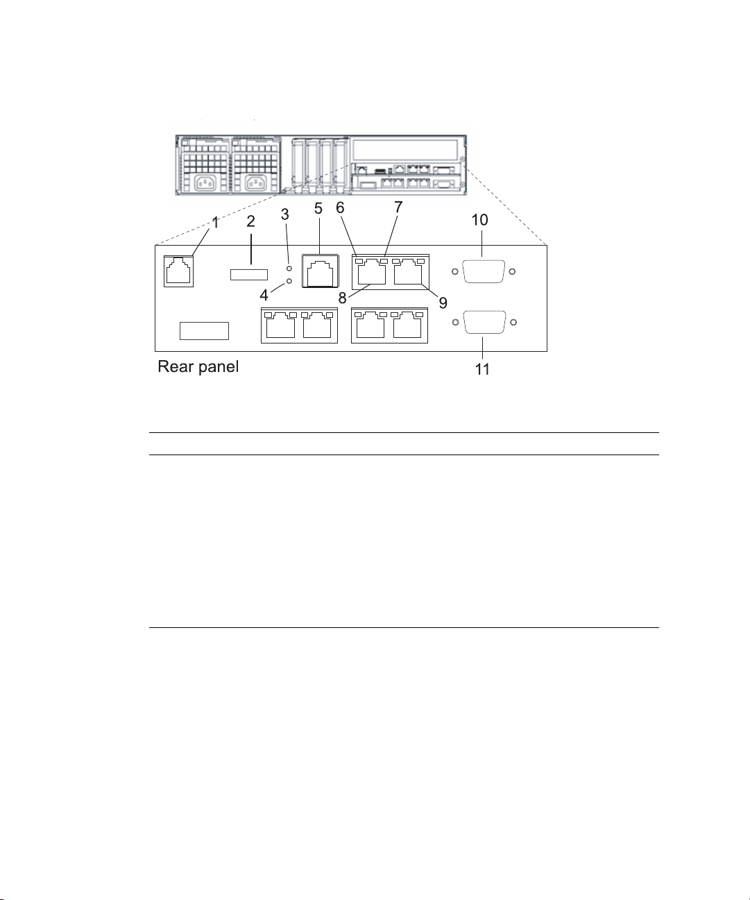
FIGURE 1-1 Outline Drawing of the Rear Panel (In the Entry-level Server)
Number Description Number Description
1 RCI port 7 ACT LED
2 USB port 8 LAN 1 port
(XSCF-LAN#1 port)
3 READY LED 9 LAN 0 port
(XSCF-LAN#0 port)
4 CHECK LED 10 UPC 1 port
5 Serial port 11 UPC 0 port
6 Link Speed LED
RCI Port
When connecting a peripheral device with an RCI connector to the server, the RCI
port is used for interlocking with a power supply and error monitoring.
1-4 SPARC Enterprise Mx000 Servers XSCF User’s Guide • January 2012
Page 23
Note – To use the RCI function, peripheral devices with the RCI connector and the
server on which the RCI function is supported are required. For the information
whether the RCI function is supported on your server, see the SPARC Enterprise
M3000/M4000/M5000/M8000/M9000 Servers Product Notes.
USB Port
The USB port (type A) is used to connect a USB device. The port is compatible with
USB 1.1. The port can be used by a system administrator or an FE to save and restore
the hardware information, or to collect log data. For the USB handling, see
Section 2.3, “Save and Restore XSCF Configuration Information” on page 2-195 and
Section 8.2.2, “Method of Collecting the Log Information” on page 8-27.
READY LED
The READY LED lights up in green. When the power supply is turned on, the
READY LED blinks. This blinking LED state indicates that the XSCF has been started
and is being initialized. When XSCF initialization is completed, the LED stays lit.
CHECK LED
The CHECK LED lights up in orange. While the XSCF is operating normally, the
LED remains off. If an abnormality occurs in the XSCF Unit, the CHECK LED turns
on. The CHECK LED can set to blink using an XSCF Shell command. This can be
used to identify the XSCF Unit even if there is no failure. For details on the
LED-related commands of the XSCF Shell, see Chapter 5 and the XSCF Reference
Manual.
Note – The Check LED turns on immediately after the server input power is turned
on.
Serial Port
The serial port (RS-232C port) uses an RJ-45 connector. The serial port is used with
the XSCF Shell to configure server settings and display the server status. An RS-232C
serial cross cable is used in the serial port. The connection between the serial port
and a PC requires an RJ-45 / RS-232C conversion cable or a conversion connector.
For details on serial port connections, see Chapter 3 and the Installation Guide for
your server.
Chapter 1 XSCF Overview 1-5
Page 24

XSCF-LAN Port (Ethernet Port)
There are two XSCF-LAN ports. Both use an RJ-45 connector and are compatible
with 10BASE-T/100BASE-T (TX). The XSCF-LAN ports are used with the XSCF Shell
and XSCF Web to perform system administrator operations, output the system
status, perform domain operations, and display the console. With a connection
between the PC/workstation and LAN, the XSCF-LAN ports are used with the XSCF
Shell and XSCF Web by system administrators or FEs to configure the system
settings, display the system status, and perform component replacement tasks. For
details on using the LAN ports, see Section 1.3, “Types of Connection to XSCF” on
page 1-15 and Chapter 3.
Link Speed LED
Located on each of the XSCF-LAN ports, the Link Speed LED is a LAN LED that
lights up in green. The Link Speed LED is turned on when a 100-Mbps LAN
connection is established, and it is not turned on when a 10-Mbps LAN connection is
established.
ACT LED
Located on each of the XSCF-LAN ports, the ACT LED is a LAN LED that lights up
in green. When the communication state is Link up, the ACT LED lights up. When
the communication state is Link down, the ACT LED light is off. The ACT LED light
is off while data is being sent/received though the associated LAN connection. So,
the ACT LED looks as if it is blinking.
UPC Port
There are two UPC ports. These ports are a connection between the XSCF Unit and
the UPS. The UPC port is used only when a UPS is connected. For details on the
connectors, see the Service Manual for your server.
XSCF Unit Panel (Front) on the Midrange Servers
FIGURE 1-2 is an outline drawing of the XSCF Unit front panel on the M4000/M5000
servers.
The XSCF Unit of the M4000/M5000 servers is a removable unit. In the
M4000/M5000 servers, for details on mounting the XSCF Unit, see the SPARC
Enterprise M4000/M5000 Servers Service Manual.
1-6 SPARC Enterprise Mx000 Servers XSCF User’s Guide • January 2012
Page 25
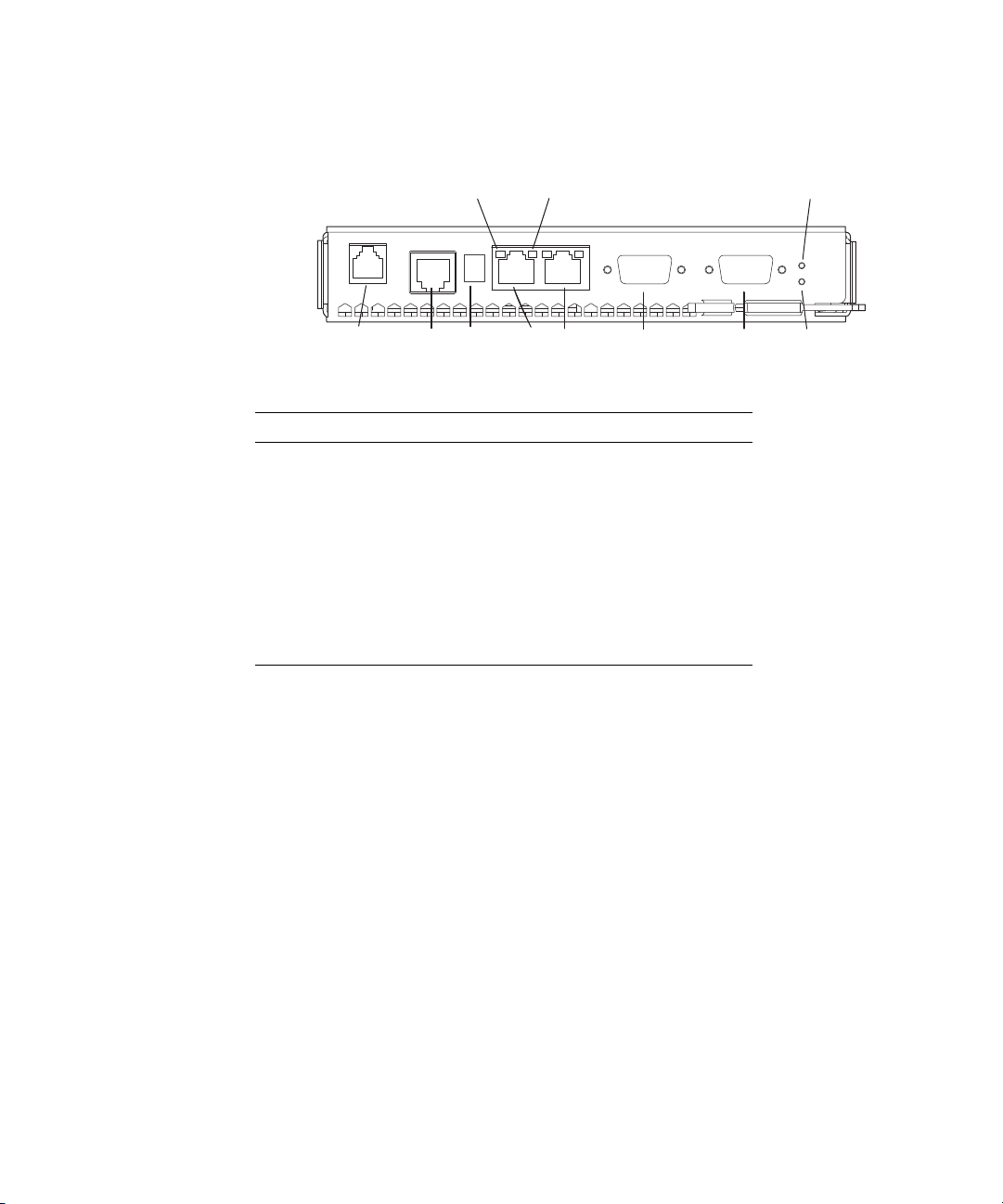
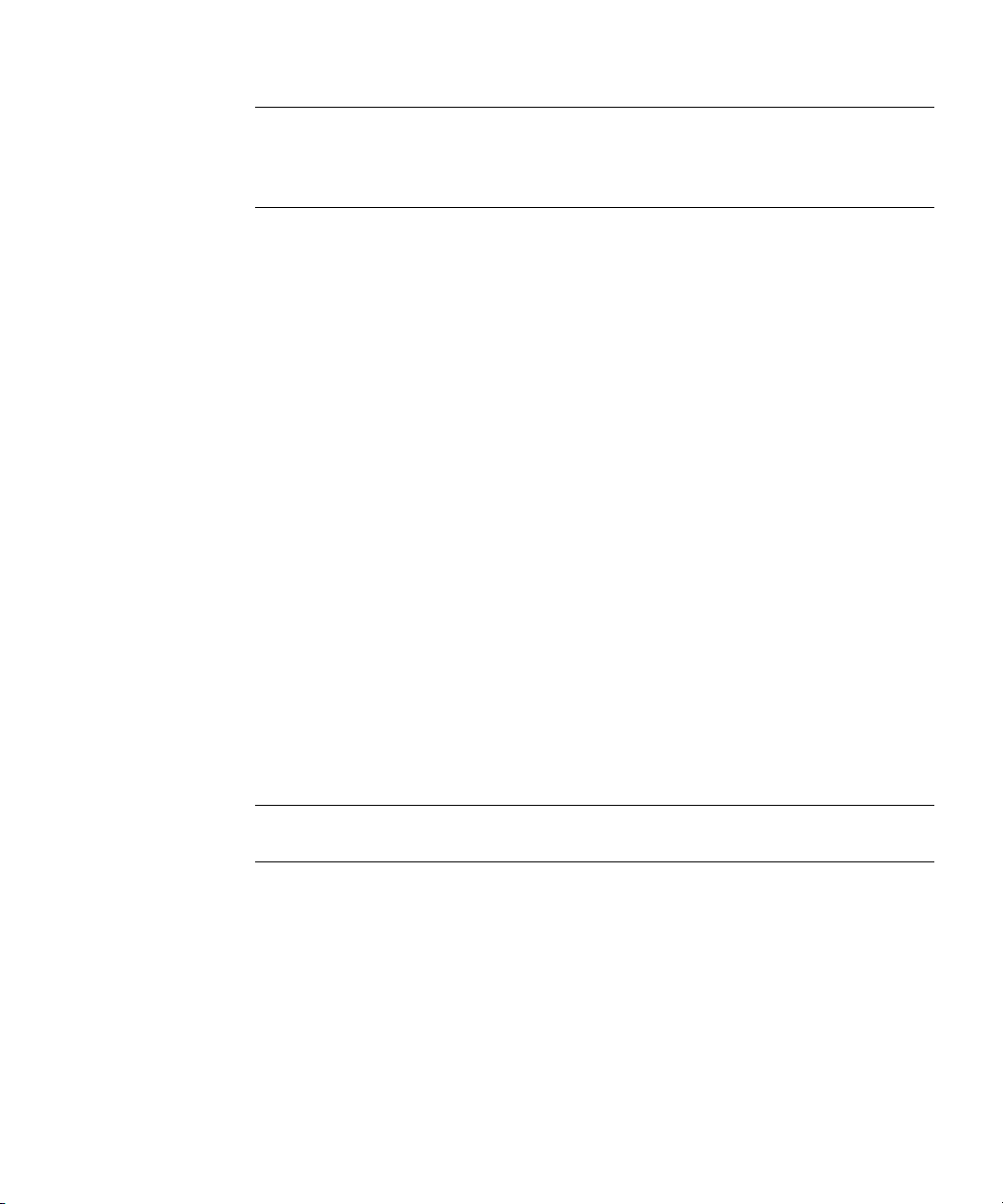
FIGURE 1-2 Outline Drawing of the XSCF Unit Front Panel (In the Midrange Servers)
XSCF Unit (Front)
67 11
12345 8 910
Number Description Number Description
1 RCI port 7 ACT LED
2 Serial port 8 UPC#1 port
3 USB port 9 UPC#0 port
4ETHERNET#1 port
(XSCF-LAN#1 port)
5ETHERNET#0 port
(XSCF-LAN#0 port)
6 Link Speed LED
10 CHECK LED
11 READY LED
The RCI port, serial port, USB port, XSCF-LAN ports, Link Speed LED, ACT LED,
UPC ports, CHECK LED, and READY LED shown in
FIGURE 1-2 have the same
functions as those of the M3000 server. For descriptions of their functions, see the
explanation of
FIGURE 1-1.
XSCF Unit Front Panels on the High-End Servers
FIGURE 1-3 includes an outline drawing of the XSCF Unit front panel on the
M8000/M9000 servers. For connections between the model and an expansion
cabinet, an XSCF Unit as shown at the bottom of
expansion cabinet.
The XSCF Unit of the M8000/M9000 servers is a removable unit. In the
M8000/M9000 servers, for details on mounting the XSCF Unit, see the SPARC
Enterprise M8000/M9000 Servers Service Manual.
FIGURE 1-3 is mounted in the
Chapter 1 XSCF Overview 1-7
Page 26
FIGURE 1-3 Outline Drawing of the XSCF Unit Front Panel (In High-End Servers)
XSCF Unit (Front)
12
34 5 6 7
8910 11
XSCF Unit (Front; in Expansion cabinet)
Number Description Number Description
1 Link Speed LED 7 RCI port
2 ACT LED 8 ACTIVE LED
3ETHERNET#0 port
(XSCF-LAN#0 port)
4ETHERNET#1 port
(XSCF-LAN#1 port)
5 USB port 11 Connector that connects the XSCF Unit for base
6Serial port
9 READY LED
10 CHECK LED
cabinet with the XSCF Unit for expansion cabinet
The Link Speed LED, ACT LED, XSCF-LAN ports, USB port, serial port, RCI port,
READY LED, and CHECK LED shown in
FIGURE 1-3 have the same functions as
those of the M3000 server. For descriptions of their functions, see the explanation of
FIGURE 1-1.
1-8 SPARC Enterprise Mx000 Servers XSCF User’s Guide • January 2012
Page 27
ACTIVE LED
The ACTIVE LED lights up in green. If the XSCF Unit is in a redundant
configuration, the ACTIVE LED indicates the active XSCF Unit.
Connector That Connects the XSCF Unit for the Base Cabinet With the
XSCF Unit for the Expansion Cabinet
The connector for connecting between XSCF Units is used to connect the Base
cabinet to an Expansion cabinet on the M9000 server. Field engineers should connect
this connector.
1.2 XSCF Functions
This section describes XSCF functions.
Monitoring the Server Status and RAS Function (Fault Management)
XSCF constantly monitors the server status, so the system can operate with stability.
If XSCF detects a system abnormality, it collects a hardware log immediately and
analyzes it to locate the fault and determine the failure status by using the Fault
Management Architecture (FMA). XSCF displays the status and, if necessary,
degrades the faulty parts, degrades the faulty domains, or resets the system to
prevent another problem from occurring. XSCF thereby maintains high system
reliability, availability, and serviceability (RAS).
XSCF Shell and XSCF Web
XSCF provides the XSCF Shell and XSCF Web that enable the user to display the
server status, operate the system, operate domains, and display the console.
XSCF Unit Diagnosis
When the input power is turned on or the XSCF is reset, XSCF performs initial
diagnostics for the XSCF itself, checks for abnormalities, displays any detected
abnormality, and reports it to the user. While the system is operating, the error
detection facility of the XSCF continues to monitor itself, and if any errors are
detected, it will report them.
Chapter 1 XSCF Overview 1-9
Page 28

Initial System Configuration Function
XSCF configures the initial hardware settings of the XSCF Unit and initializes
hardware as required to start the Oracle Solaris Operating System (Oracle Solaris
OS). XSCF also controls the initial system configuration information.
XSCF User Account Control
XSCF controls the user accounts for XSCF operations.
The basic types of user account privileges controlled by XSCF are listed below. The
server provides the XSCF Shell and XSCF Web, but their privileges depend on the
user privilege (type).
■ System administrator
■ Domain administrator
■ Operator
■ Field engineer
For details on the user privileges, see the Administration Guide.
Security
XSCF provides an encryption function using Secure Shell (SSH) or Secure Sockets
Layer (SSL) and an audit function. Any operation error or unauthorized attempt to
access XSCF functionality is recorded in a log. The system administrator can use this
information for troubleshooting system errors and unauthorized login attempts.
Power Control for the Server System and Domains
XSCF has power-on and power-off control of the server. The user can press the
POWER switch on the operator panel to turn on or off the whole system, or the user
can use XSCF to turn on and off the supply of power to the whole system or
individual domains.
The user can power on and off the server by using XSCF as follows:
■ Power on/off the server or a domain
The user can turn on, turn off, or reset the server by using the XSCF Shell
command from a remote terminal, which is connected to XSCF over a LAN or
serial connection. When the user instructs power off, the Oracle Solaris OS is
automatically shut down, and then power will be turned off.
1-10 SPARC Enterprise Mx000 Servers XSCF User’s Guide • January 2012
Page 29

■ Automatically shut down and cancel a power on operation when an error is
detected
If a system abnormality occurs, the Oracle Solaris OS is automatically shut down,
and the subsequent power on will not be started. This can minimize damage to
the system.
■ Control power during power failure and power restoration
XSCF performs the following operations when a power failure occurs that causes
the system to turn off:
■ When a power failure occurs:
XSCF performs emergency power off when the power failure occurs. When a UPS
is connected, any running domains may also be shut down automatically. For a
momentary power failure, XSCF may allow the system to continue working
without any shutting down.
■ When power is restored:
The system can be set up such that XSCF automatically turns on the power to the
server, then starts up the domains, relieving the system administrator of extra
work.
For details on operation settings for a power failure, see Section 4.4.10, “Shutdown
Wait Time Administration” on page 4-23.
Support of Hot-Swapping of Components
XSCF supports maintenance work with the XSCF Shell during hot-swapping of
components. For details on the XSCF Shell, see Chapter 5.
Component Configuration Recognition and Temperature/Voltage
Monitoring
XSCF monitors component information such as the configuration status and the
serial numbers of components in the server. If an abnormality is detected in the
component configuration, it is displayed and reported to the user. XSCF periodically
monitors and displays the temperature inside the server, the ambient temperature,
component temperatures, voltage levels, and FAN status.
Chapter 1 XSCF Overview 1-11
Page 30

Internal Cabinet Configuration, Recognition, and Domain Configuration
Control Functions
To use XSCF, you can display the system configuration status, and create and change
domain configuration definitions. It also provides domain start and stop functions,
mainly for its own use. In the server, the user can configure a domain as a single
Physical System Board (PSB) that has CPU, memory, and I/O device, or a PSB
logically divided, which are the eXtended System Boards: (XSBs). The user assigns a
domain and the Logical System Boards (LSBs) number that can be referenced from
the domain to the XSBs for control of the domain configuration. The type of the PSB
not logically divided is called Uni-XSB and the type of the PSB logically divided into
four is called Quad-XSB.
For details on domain configuration, see the Overview Guide for your server and
Chapter 2. Also, for each term, see Glossary.
Note – In the M3000 server, the domain configuration control function is not
available. The M3000 server consists of a single PSB (Uni-XSB) equipped with one
CPU, and operates with one domain only. Unlike the M4000/M5000/M8000/M9000
servers, the user cannot configure a domain by logically dividing the PSB.
Dynamic Reconfiguration Function
XSCF supports dynamic system board configuration change operations while the
domains are operating. Dynamic reconfiguration (DR) of a domain can be achieved
using XSCF. For details on DR, see the Dynamic Reconfiguration User’s Guide.
Note – In the M3000 server, the DR function is not available.
Console Redirection Function
XSCF provides a function that displays the OS console of the Oracle Solaris OS of
each domain. With an SSH (Secure Shell) or telnet connection to XSCF, the user can
access the console of any domain in the system. For details on the console, see
Chapter 3.
1-12 SPARC Enterprise Mx000 Servers XSCF User’s Guide • January 2012
Page 31

Capacity on Demand Function
Capacity on Demand is an option to purchase spare processing resources (CPUs) for
your server. The spare resources are provided in the form of one or more CPUs on
COD boards that are installed on your server. When you need the spare processing
resources (CPUs) for the server, XSCF assists the operation to add or delete the
resources. For details on COD, see the COD User’s Guide.
Note – In the M3000 server, the COD function is not available.
Functions for Monitoring and Notification During Operation
XSCF constantly monitors the system operating status, FAN status, ambient
temperature, etc. Using the network function of the cabinet, XSCF accesses the server
to provide the following services:
■ Monitoring the server even when the Oracle Solaris OS is inactive.
■ Enabling remote operation of the server.
■ Reporting error messages by email to specified addresses. For details, see
Chapter 6.
■ Trapping notification with the SNMP Agent functions. For details, see Chapter 7.
Hardware Fault Information Collection (Hardware Log Collection)
XSCF collects hardware fault information and saves it on the XSCF itself.
The XSCF hardware failure log makes it possible to identify the location of a failure.
The log also provides assistance in anticipating failures on the server and
immediately reports precise information about failures to the user.
For details on error messages and their contents, see Appendix A and Appendix B .
The displayed messages types are as follow:
■ An initial diagnostic message is displayed at system startup.
■ XSCF monitors the network configuration. If an error is detected, an error
message is generated and displayed.
■ XSCF monitors the status of the power supply, FAN, voltage, system board,
memory, CPU, and other components. If an error is detected in a component, an
error message is generated and displayed. Based on the error message, the system
administrator can easily identify the component that needs to be replaced.
■ XSCF monitors the temperatures of the cabinet and CPU. If an abnormal
temperature is detected, an error message is generated and displayed. The error
messages make it possible to prevent the system from rising to a higher
temperature and to prevent system instability.
Chapter 1 XSCF Overview 1-13
Page 32

Firmware Update Function
The web browser and commands can be used to download new firmware image
(XSCF firmware and OpenBoot PROM firmware) without stopping the domain and
to update firmware without stopping other domains. To complete updating the
OpenBoot PROM firmware in the target domain, the domain must be rebooted. For
details on updating firmware, see Chapter 8.
1.2.1 Major Differences Among the Server Models
TABLE 1-1 shows the major differences related to XSCF, among the models of the
M3000/M4000/M5000/M8000/M9000 servers.
TABLE 1-1 Major Differences Between the Models
Item / Model
XSCF Unit Fixed on MBU.
XSCF redundancy Not available Not available Available
Number of domains 1 Max 2 (M4000)
Number of CPUs 1 Max 4 (M4000)
Mounted processor SPARC64 VII+
System board
division
Memory mirroring Not available Available Available
DR Not available Available Available
COD option Not available Available Available
M3000 server
(Entry-level)
Replaceable in units of
MBU.
SPARC64 VII
Not available Available Available
M4000/M5000 servers
(Midrange)
Replaceable Replaceable
Max 4 (M5000)
Max 8 (M5000)
SPARC64 VII+
SPARC64 VII
SPARC64 VI
M8000/M9000 servers
(High-end)
Max 16 (M8000)
Max 24 (M9000)
Max 16 (M8000)
Max 32 (M9000)
Max 64 (M9000 with
expansion cabinet)
SPARC64 VII+
SPARC64 VII
SPARC64 VI
For an overview of the system board and the component, see the Overview Guide and
the Service Manual for your server.
1-14 SPARC Enterprise Mx000 Servers XSCF User’s Guide • January 2012
Page 33

1.3 Types of Connection to XSCF
SSH/telnet/
https
connection
SSH/telnet/
https
connection
Router
Server
XSCF-LAN
Ethernet connection
Connection to the
serial port
Terminal
Terminal
Terminal
:
User
LAN
Domain
Domain
XSCF
This section outlines types of connection to the XSCF.
XSCF enables access to the server over a serial port or from networks connected to
XSCF-LAN.
FIGURE 1-4 Connections to XSCF (In the Midrange Servers)
FIGURE 1-4 outlines the connections to the XSCF.
Note – In the systems with two XSCF Units, the XSCF Unit is in a redundant
configuration, and there are physically twice as many XSCF-LAN ports and serial
ports. Also, in the entry-level server, there is only one domain.
Chapter 1 XSCF Overview 1-15
Page 34

The following connections in the XSCF Unit connection configuration shown in
FIGURE 1-4 are described below:
■ Serial port connection
■ XSCF-LAN Ethernet connection
Serial Port Connection
The serial port enables workstations, PCs, and ASCII terminals to connect to the
XSCF through the serial (RS-232C) port. The user can use the XSCF Shell and access
the domain console through the XSCF Shell.
XSCF-LAN Ethernet Connection
XSCF-LAN Ethernet enables workstations and PCs to connect to the XSCF through
the XSCF-LAN port. The following can be used with XSCF-LAN Ethernet:
■ XSCF Shell via a SSH or telnet connection
■ XSCF Web from a web browser running on the terminal
■ Domain console access
■ Mail reports
■ SNMP notification
For details on these XSCF functions, see the following chapters:
■ Settings for each function: Chapter 2
■ Shell terminal and console connections: Chapter 3
■ XSCF Shell: Chapter 5
■ XSCF mail functions: Chapter 6
■ XSCF SNMP Agent functions: Chapter 7
■ XSCF Web: Chapter 9
1.3.1 Examples of LAN Connection Operations
The XSCF Unit has two 10/100 Mbps XSCF-LAN two ports. TA BLE 1- 2 to TABLE 1-4
outlines three XSCF-LAN operation examples.
1-16 SPARC Enterprise Mx000 Servers XSCF User’s Guide • January 2012
Page 35

TABLE 1-2 XSCF-LAN Operation Examples 1
LAN Name Operation
XSCF-LAN#0 port • For system administrator operation
The system administrator can control the server, control
domains, and display the console using the XSCF Shell.
XSCF-LAN#1 port • For field engineer operation.
Field engineers can configure the server and perform
maintenance tasks using the XSCF Shell.
• For remote maintenance service operation
TABLE 1-3 XSCF-LAN Operation Examples 2
LAN Name Operation
XSCF-LAN#0 port • For system administrator operation
• For remote maintenance service operation
XSCF-LAN#1 port Not used
Note – The serial port is used by maintenance engineers.
TABLE 1-4 XSCF-LAN Operation Examples 3
LAN Name Operation
XSCF-LAN#0 port • For system administrator operation
• For maintenance operation
• For remote maintenance service operation
XSCF-LAN#1 port Same as above
Note – The two XSCF-LAN ports are used for the same purpose (alternate path
configuration). For details on these connections, see Chapter 3.
Caution – IMPORTANT - The IP address of XSCF-LAN#0 and the IP address of
XSCF-LAN#1 must be specified in different subnet addresses.
Chapter 1 XSCF Overview 1-17
Page 36

XSCF-LAN Redundancy
XSCF
System
Failure of
path or XSCF
a) No redundant LAN
XSCF
System
Failure of a path
b) Redundant LAN
In the M3000/M4000/M5000/M8000/M9000 servers, the XSCF-LAN paths can be
made redundant (duplicated). If a LAN failure occurs, it contributes significantly to
reducing system availability. However, in a system equipped with a duplicate LAN,
the routes (paths) in the remaining network can be used even if one subnetwork is
faulty. In this way, high system availability can be achieved.
FIGURE 1-5 and FIGURE 1-6 show the network, which belongs to one or two different
subnets. In
connections and the thick lines represent network connections.
FIGURE 1-5 shows configurations with a single mounted XSCF Unit: one where the
LAN is not redundant, and the other with a redundant LAN.
FIGURE 1-5 XSCF-LAN Redundancy (In Entry-level and Midrange Servers)
FIGURE 1-5 and FIGURE 1-6, the ordinary lines represent subnetwork
In the configuration examples shown in FIGURE 1-6, the XSCF-LANs are redundant
and the XSCF Unit is in a redundant configuration.
In the configuration with a single XSCF Unit, XSCF-LAN cannot be used by any
XSCF Unit failure even if the XSCF-LANs are redundant (duplicated). If one
subnetwork is faulty, the remaining path can be used (
XSCF Unit is faulty, XSCF initiates failover (
availability can be achieved.
1-18 SPARC Enterprise Mx000 Servers XSCF User’s Guide • January 2012
FIGURE 1-6-c). If the active
FIGURE 1-6-d). Therefore, high network
Page 37

Active
XSCF
Standby
XSCF
System
Failure of a path
c) A subnet failed
Active
XSCF
Standby
XSCF
System
XSCF failed
d) XSCF failed
Failover
FIGURE 1-6 Two XSCF -LANs a nd Two XSC F Units Configuration (In High-End Servers)
For details on LAN configurations and connections, see Chapter 3. For details on
specifying IP addresses, see Chapter 2.
Chapter 1 XSCF Overview 1-19
Page 38

1.3.2 NTP Configuration and Time Synchronization
The system uses the XSCF Unit clock for the system standard time.
The domains in the server synchronize their times based on the XSCF Unit clock
when the domains are started. The XSCF Unit clock can be adjusted to the exact time
through a network connection to an external NTP server. In that way, the XSCF Unit
becomes the NTP server and an NTP client.
Only domains may specify XSCF as an NTP server. Also, when the XSCF is used as
an NTP server, XSCF permits only the confirmation of the time synchronization to
the inquiry from the NTP client.
Note – Alternatively, the domains can synchronize their times through a connection
to an external NTP server. However, there is a possibility that time differences exist
between the XSCF and the domain. If you connect the domain to an external NTP,
connect the high rank NTP server that supplies the time of the same accuracy as the
domain as for XSCF.
For details about NTP server setting, see Chapter 2.
TABLE 1-5 outlines XSCF and domain time synchronization methods.
TABLE 1-5 XSCF Unit and Domain Time Synchronization
Client Primary NTP Server Time Synchronization Method
Domain XSCF Unit The domain time is adjusted to the XSCF Unit clock time.
XSCF Unit operates as the NTP server.
External NTP server The domain time is adjusted to the standard time of the external NTP
server.
XSCF No connection The XSCF Unit time is the time in initial system settings or the time
set by the setdate(8) command. For details on the setdate(8)
command, see the XSCF Reference Manual.
External NTP server The XSCF Unit time is adjusted to the standard time of the external
NTP server.
1.3.3 The CD-RW/DVD-RW Drive Unit and Tape Drive Unit
In the M3000 server, one domain monopolizes the DVD drive unit. In the
M4000/M5000 servers, the domain that uses a minimum XSB number of number 0 of
the MotherBoard Unit (MBU#0) can use the CD-RW/DVD-RW drive unit and tape
drive unit (hereafter collectively called DVD drive/tape drive unit).
1-20 SPARC Enterprise Mx000 Servers XSCF User’s Guide • January 2012
Page 39

In the M8000/M9000 servers, a basic cabinet and an expansion cabinet contain one
DVD drive/tape drive unit respectively, and they are assigned to a single operating
domain of each cabinet. The DVD drive/tape drive unit can be used by assigning it
to a specific card port on the I/O unit. To assign a different port, specify the unit by
using the XSCF Shell. For details on this DVD drive/tape drive unit setting, see
Chapter 2.
Note – Do not use the CD_RW/DVD-RW drive unit and the tape drive unit at the
same time.
1.4 XSCF User Interfaces
This section describes the XSCF user interfaces.
1. XSCF Shell (Ethernet Connection):
A set of XSCF Shell commands you can use from a PC or a terminal connected to the
XSCF over an XSCF-LAN Ethernet connection using SSH or telnet. Also, you can
switch to domain console.
2. XSCF Shell (Serial Connection):
A set of XSCF Shell commands you can use from a PC or terminal directly connected
to the XSCF by a serial cable. Also, you can switch to domain console.
3. XSCF Web:
A set of browser user interface (BUI) operations you can use from a web browser
connected to the XSCF over the XSCF-LAN Ethernet.
4. XSCF SNMP Agent functions:
SNMP manager commands used to monitor the operation of the server's network
functions.
5. XSCF mail functions:
Sends email reports of the system status.
For details about connecting to XSCF consoles, see Chapter 3.
Chapter 1 XSCF Overview 1-21
Page 40

Caution – IMPORTANT – To use the function as explained previously, you must
create your XSCF account. Create your account before you start using the XSCF
functionality. In addition, create an account for your field engineer (FE) with the
privilege of fieldeng during initial setup.
To use these XSCF interfaces, users need to log in to XSCF with an XSCF user
account, and then enter a password. When a user successfully logs into XSCF but the
user leaves the session without any activity for a specified length of time, XSCF
automatically logs the user out. XSCF monitors user operations and keeps a detailed
access record containing the names of users who logged in and login times. For
details on the user privilege required for control of this access record, see
Section 1.4.1, “User Accounts and User Privileges” on page 1-23.
For details on login, see Chapter 5. For details on authentication and Web functions,
see Chapter 9. For details on user account registration and mail function settings, see
Chapter 2.
TABLE 1-6 outlines XSCF Functions and Connection Ports.
TABLE 1-6 XSCF Functions and Connection Ports
Functions Contents Serial port
XSCF Shell • Monitors the server
The status of the system can be checked.
• System power can be controlled from a remote location
The system power can be turned on and off and the system can
be rebooted from a remote location.
• Displays the server configuration
The internal configuration of the server can be checked.
• Set up the server
Many server settings can be set.
• Supports system maintenance
Issues instructions for firmware update operation and
component replacement.
• OS console function
You can access to the OS console and/or OpenBoot PROM
prompt.
SS
XSCF-LAN
Ethernet
1-22 SPARC Enterprise Mx000 Servers XSCF User’s Guide • January 2012
Page 41

TABLE 1-6 XSCF Functions and Connection Ports (Continued)
Functions Contents Serial port
XSCF Web Provides the same functions as the functions of the XSCF Shells,
but provides graphical displays for easier operation.
Mail report Mail notification in the event of a failure enables prompt action
to be taken.
SNMP trap
report
Enables consolidated control for system administration in
conjunction with SNMP manager.
_
_S
_S
Note – Symbols: S: Supported. — : Not supported.
1.4.1 User Accounts and User Privileges
The system administrator and field engineers log in to XSCF with XSCF user
accounts that allow them to refer to the status of any part of the entire system and
work on all parts of the system. Each domain administrator uses an XSCF user
account that enables system control of one domain.
For the server, the system administrator must consider both a user account that
controls the whole system and a user account that administers each domain. When a
user is registered, the user is assigned a privilege that controls the XSCF operations
available to that user. This is referred to as the user privilege of the registered user
account.
XSCF-LAN
Ethernet
S
For example, to set up a domain administrator, the user privilege for the domain is
specified. Moreover, you can provide system monitoring privileges, for instance,
without system operation privileges. You can also limit privileges to specific
domains.
TABLE 1-7 lists user privilege names and outlines the user privileges.
Chapter 1 XSCF Overview 1-23
Page 42

TABLE 1-7 User Privilege Names and Descriptions
User privilege Outline Description of Defined Contents
domainop@n Reference of the status of any
part of one entire domain_n
• Can refer to the status of any hardware mounted
in a domain_n.
• Can refer to the status of any part of a domain_n.
• Can refer to the information of all system boards
mounted.
domainmgr@n Power supply operations and
reference of the status of only
one domain_n
• Can power on, power off, and reboot a domain_n.
• Can refer to the status of any hardware mounted
in a domain_n.
• Can refer to the status of any part of a domain_n.
• Can refer to the information of all system boards
mounted.
domainadm@n Control of only one
domain_n
• Can operate all hardware mounted in a domain_n.
• Can refer to the status of any hardware mounted
in a domain_n.
• Can operate all of a domain.
• Can refer to the status of any part of a domain_n.
• Can refer to the information of all system boards
mounted.
platop Reference of the status of any
part of the entire system
• Can refer to the status of any part of the entire
server but cannot change it.
platadm Control of the entire system • Can operate all hardware in the system.
• Can configure all XSCF settings except the
useradm and auditadm privilege settings.
• Can add and delete hardware in a domain.
• Can do the power operation of a domain.
• Can refer to the status of any part of the entire
server.
useradm User account control • Can create, delete, invalidate, and validate user
accounts.
• Can change user passwords and password
profiles.
• Can change user privileges.
auditop Reference of the Audit status • Can refer to the XSCF access monitoring status
and monitoring methods.
1-24 SPARC Enterprise Mx000 Servers XSCF User’s Guide • January 2012
Page 43

TABLE 1-7 User Privilege Names and Descriptions (Continued)
User privilege Outline Description of Defined Contents
auditadm Audit control (Note) • Can monitor and control XSCF access.
• Can delete an XSCF access monitoring method.
fieldeng Field engineer operations • Allows field engineers to perform the maintenance
tasks or change the server configuration.
none None • When the local privilege for a user is set to none,
that user has no privileges, even if the privileges
for that user are defined in LDAP.
• Setting a user’s privilege to none prevents the
user’s privileges from being looked up in LDAP.
Note – (@n) "@domain number" is added behind the privilege name for the target
domain privilege. (Example: The domainadm for domain ID 1 is domainadm@1).
Also, a user account can have privileges over multiple domains, and not just the
target domain.
For details on user privileges, see the Administration Guide. For details on setting up
user accounts and setting user privileges, see Section 2.2.2, “User Account
Administration” on page 2-36.
Chapter 1 XSCF Overview 1-25
Page 44

CHAPTER
2
Setting Up XSCF
This chapter explains how to set up XSCF.
2.1 XSCF Setup Summary
Each XSCF function must be configured before it can be used. Make the following
settings:
■ User Account Administration (required)
■ Network Configuration (required)
■ Time Administration (required)
■ SSH/telnet Administration (optional)
■ Mail Administration (optional)
■ LDAP Administration (optional)
■ Active Directory Administration (optional)
■ LDAP/SSL Administration (optional)
■ Https Administration (optional)
■ Log Archiving Administration (optional)
■ Audit Administration (optional)
■ SNMP Administration (optional)
■ Remote Maintenance Service Setting (optional) (see the following Note 1)
■ Domain Configuration (required) (see the following Note 2)
■ System Board Configuration (required) (see the following Note 3)
■ Domain Mode Configuration (optional)
■ Locale Administration (optional)
2-1
Page 45

■ Altitude Administration (required)
■ DVD Drive/Tape Drive Unit Administration (optional)
■ COD Administration (optional) (see the following Note 4)
Note – (1) This document does not provide details on the remote maintenance
service functions. For the information of the remote maintenance service, see the
Product Notes for your server.
Note – (2) Domain configuration is not required in the M3000 server. Some of the
options can be configured. For details, see Section 2.2.13, “Domain Configuration”
on page 2-146.
Note – (3) In the M3000 server, system board cannot be configured. System board
has been configured by default and you cannot change the setting. However, you
can refer to the system board information.
Note – (4) In the M3000 server, COD is not available.
After the XSCF is set up, the settings are automatically saved in XSCF internally and
in the operator panel. Once you have configured the XSCF, it requires no day-to-day
management. However, you can save or restore the XSCF setup configuration
information. For details of saving or restoring XSCF configuration information, see
Section 2.3, “Save and Restore XSCF Configuration Information” on page 2-195.
About Setup Flow
The XSCF Shell or XSCF Web can be used to set up XSCF.
Each setting items and the step summary are explained in Section 2.1.1, “Setup
Summary by the XSCF Shell” on page 2-3 and Section 2.1.2, “Setup Summary Using
the XSCF Web” on page 2-12. Details on each step are provided in Section 2.2,
“Specifying the XSCF Settings” on page 2-15.
2-2 SPARC Enterprise Mx000 Servers XSCF User’s Guide • January 2012
Page 46

2.1.1 Setup Summary by the XSCF Shell
This section describes the step summary of setup using the XSCF Shell. This
procedure contains examples of command usage and setting items. For details on
settings, see the corresponding parts of Section 2.2, “Specifying the XSCF Settings”
on page 2-15.
Note – Establish one-to-one communication between the PC and XSCF during the
initial setup.
1. Connect to XSCF by serial connection and log in.
To configure XSCF, the system administrator or a field engineer first uses the
XSCF default user account. Before an appropriate user account for the user
environment is created, log in with the following default user account and
password:
■ Default user account: default
The user privileges are useradm, platadm.
■ Default password:
The default password is not input directly on the keyboard. Instead, after the
default user account is input, the mode switch of the operator panel is
operated as follows.
a. If Locked, change to Service. (Or if Service, change to Locked)
b. Press return. Keep the status for more than 5 seconds.
c. Change to Locked. (Or change to Service)
d. Press return.
This mode switch operation is done within one minute. When one minute is
passed, the authentication timeout occurs.
■ To begin the configuration, connect the XSCF Shell over a serial connection
using any terminal software. The shell can be used immediately following
connection to the serial port.
<Terminal screen image>
login:
■ Log in with the default user account. Follow the instructions to change the
mode switch of the operator panel, and operate the mode switch within one
minute.
Chapter 2 Setting Up XSCF 2-3
Page 47

login: default
Change the panel mode switch to Service and press return...
(Operation : Locked state -> Service -> Return)
Leave it in that position for at least 5 seconds. Change the panel
mode switch to Locked, and press return...
(Operation : Wait more than 5 seconds -> Service state ->
Locked -> Return)
XSCF>
When the server is running normally, the mode switch is set to the Locked position.
2. Set the password policy.
• Display and set a password policy. showpasswordpolicy(8),
setpasswordpolicy(8)
(See Section 2.2.2, “User Account
Administration” on page 2-36)
(This table includes the example of setting items and command used. It is similar
thereafter.)
3. Create an XSCF user account, password and privileges.
■ Create at least one user account with the user privileges of platadm and useradm:
XSCF> adduser yyyy
XSCF> password yyyy
XSCF> setprivileges xxxxxx
(See Section 2.2.2, “User Account Administration” on page 2-36)
(The screen is an operating procedure image.)
■ The default user account is publicly available information. When installation is
completed, create an appropriate user account for the user environment and log
in again with the new user account. For details on the user privileges, see the
Administration Guide.
■ When you add the user account, use the showuser(8) command with -l option
to confirm that there is no illegal user account in the user account list.
Note – In preparation for maintenance work, please create an account for a field
engineer (FE) with the privilege of fieldeng during the initial set up.
2-4 SPARC Enterprise Mx000 Servers XSCF User’s Guide • January 2012
Page 48

4. Set the time.
• Set and display the time zone.
• Set and display the XSCF time.
• Reset and display the time subtraction
between the XSCF and the domain.
showtimezone(8), settimezone(8),
showdate(8), setdate(8)
showdateoffset(8)
resetdateoffset(8)
(See Section 2.2.6, “Time Administration”
on page 2-92)
■ When the system time is updated, the XSCF reset is done and the XSCF session is
disconnected. Please log in again to the XSCF using the new user account.
■ NTP settings (setntp(8)) are done after the Network settings or the Domain
Configuration.
5. Configure the SSH/telnet settings.
• Select SSH or telnet, and set SSH access control
from domain.
• Display and specify the timeout monitoring
period.
■ XSCF reset is required to enable SSH, to disable telnet, and to set the SSH access
setssh(8), settelnet(8),
showautologout(8),
setautologout(8)
(See Section 2.2.7, “SSH/Telnet
Administration” on page 2-104)
control from domain. Go to the next step when you reset it later. If you want to
reset XSCF immediately, use the rebootxscf(8) command. After the XSCF reset,
the XSCF session is disconnected. Log in again to the XSCF.
■ You can enable SSH and telnet at the same time. However, the telnet connection is
not a secure connection protocol. We recommend that when you enable SSH that
you disable telnet.
6. Confirm the XSCF host public key.
■ Before using SSH for XSCF-LAN connection, record the fingerprint. Or, copy the
text data of the host public key and save the data to a specific directory of the
client. (The following screen is an example.)
Chapter 2 Setting Up XSCF 2-5
Page 49

XSCF> showssh
SSH status: enabled
SSH DSCP: accept
RSA key:
ssh-rsa
AAAAB3NzaC1yc2EAAAABIwAAAIEArmf46B4xSvunUNZPWOi4mRbqO9hsunxHitwR/
0P6NTQbNK8BqCpCsyzK6nfjrARztO1rgXIdFfXLDEIY2hudEkuMCjyorX1HK+d8WH
C7eydTCM8Edwwtwm0Q4o66peB/QwI/OL4lDCNRg+4aGyWUHZBwmiwahum+7MJDCKs
fKKM=
Fingerprint:
1024 14:75:fd:5c:e1:68:79:f6:db:cb:a7:36:25:53:25:9a
DSA key:
ssh-dss
AAAAB3NzaC1kc3MAAACBAMMG1ewTyceFX7EnKuDIp1BVnuxf+UTtALVinkfXLQbUn
gn84G8xp9GPnWOpNqiWXxAL8wInQrpz9wFd7n4sZk74HALM+gIhpjbpdXR76FpEvO
MzCi6qYuv4yQ/0+uKCHmJEfzIOvQnDoofVElXYRKxTIyQY5+mtsf+44IoGzJbxAAA
AFQCTNSxe0+5hbDziCOlgvch7FdUM3QAAAIBKGSbFr3XMYxubT7ViDHHIFgFpjEMw
DREJD05g7XwlslgFX4Ff2nqItepyfnok/CeDi1bv1Xs0JGAGsbcwpBeKe7YcSepM3
xe8vGXSIdVqGbfDvqbO9P1q1n58qEKTA2Cj5L9a+6usSYfKHOSDhnvX3R8/Hk+Iiy
6EUaVSaJUHjgAAAIAZ+qQahRLAMuOq5FCuQ000xgfZzExRBIa1Q7sBhMTrg1dksKP
+yPN9YjIw6QJXUD69acCWHD+nIKBTnSdO/NdwxDRKU2+9cOvNriUpbs5RoZgiCNCd
7nMMQUMFTzc78nd3w+pcjD5mBB6kELKuQurWbIDELTgYJcfm52C9TlR5WA==
Fingerprint:
1024 e2:66:1a:c8:8f:37:6f:ec:6c:2a:d4:93:a7:6f:dc:5c
7. Installing the user public key.
■ Before using the SSH user key for an XSCF-LAN connection, generate a user
private key and a user public key for a created XSCF user account with your
client software. Then install the user public key to XSCF.
• Generate the SSH user key. (Set in client)
• Display, Install, and Delete the SSH user public
key.
2-6 SPARC Enterprise Mx000 Servers XSCF User’s Guide • January 2012
showssh(8), setssh(8)
(See Section 2.2.7, “SSH/Telnet
Administration” on page 2-104)
Page 50

8. Configure the network.
• Display and set the DSCP.
• Display XSCF network settings (enable/disable, IP
address, netmask) and configure/remove an XSCF
network.
• Display and set XSCF host name. showhostname(8),
• Display XSCF route settings (destination IP address,
gateway, netmask, interface) and configure an XSCF
route.
• Display and make the DNS settings (name servers,
search paths, add/delete).
• Display and set the IP packet filtering rules. showpacketfilters(8) ,
• Apply network settings. applynetwork(8)
■ Perform the applynetwork(8) command to apply the network settings. To
showdscp(8), setdscp(8),
shownetwork(8),
setnetwork(8)
sethostname(8)
showroute(8), setroute(8)
shownameserver(8) ,
setnameserver(8)
setpacketfilters(8)
(See Section 2.2.1, “Network
Configuration” on page 2-16)
complete the network settings, the XSCF reset is required. Go to the next step
when you reset it later. When you want to reset it now, perform the
rebootxscf(8) command to apply the settings. Then, the XSCF reset is done and
the XSCF session is disconnected. Please connect the XSCF and log in to the XSCF
again.
■ Here, when you set up the XSCF by the XSCF-LAN connection, please change the
cable from the serial port to the XSCF-LAN port. (Change the serial cable to the
LAN cable.) When you use the controller that converts the RS-232C interface and
LAN interface, you do not need to change the cable. Reconnect to the XSCF using
the new user account and the new IP address and login to the XSCF again.
For details on connecting the SSH, telnet, and serial port, and login to the XSCF,
see Chapter 3. Moreover, the telnet connection is not a secure connection protocol.
We recommend that you use SSH.
During login using SSH on XSCF Shell (Ethernet connection), you are prompted
to confirm the authenticity of the fingerprint of the host public key. The reply is
"yes" if the fingerprint is the same as the memo in Step 6. If the reply is not the
same, please confirm that the IP address is correct and not duplicated. There is a
possibility that IP address spoofing has occurred.
Chapter 2 Setting Up XSCF 2-7
Page 51

RSA key fingerprint is xxxxxx
Connecting? [yes|no] : yes
Type the passphrase you have already set in the case that you would be using
SSH with user key authentication.
Enter passphrase for key ’/home/nana/.ssh/id_rsa’ :xxxxxxxx
Warning: No xauth data; using fake authentication data for X11
forwarding.
Last login: Fri Sep 1 10:19:37 2006 from client
9. Configure the mail settings.
• Display mail notification settings, and
configure and test mail notification.
showsmtp(8), setsmtp(8),
showemailreport(8),
setemailreport(8)
(See Section 2.2.12, “Mail
Administration” on page 2-143)
After this, configure the user accounts.
To manage user accounts, you can either configure the XSCF local accounts or you
can configure the user accounts to authenticate against a remote user database, such
as Lightweight Directory Access Protocol (LDAP), Active Directory, or LDAP/SSL.
Note – Lightweight Directory Access Protocol (LDAP): Protocol used to access
directories and databases in TCP/IP networks.
Active Directory: Active Directory is a distributed directory service from Microsoft
Corporation.
LDAP/SSL: LDAP/SSL is a distributed directory service like Active Directory.
LDAP/SSL offers enhanced security to LDAP users by way of Secure Socket Layer
(SSL) technology.
Before using an LDAP, an Active Directory, or an LDAP/SSL server, download a
certificate, create a public key, and perform user registration in the applicable
directory in the user environment.
If you are an Active Directory user, you cannot upload a user public key. When you
set the user public key to XSCF before XCP1100, delete the user public key. The
Active Directory users can access to XSCF via SSH by using the password
authentication and can login to XSCF.
2-8 SPARC Enterprise Mx000 Servers XSCF User’s Guide • January 2012
Page 52

This manual does not provide details on LDAP, Active Directory, and LDAP/SSL, so
see the available LDAP, Active Directory, and LDAP/SSL manuals.
10. Configure the LDAP settings.
■ Configure XSCF as an LDAP client.
• Display and set LDAP client information. showldap(8), setldap(8)
(See Section 2.2.3, “LDAP Administration”
on page 2-44)
11. Configure the Active Directory settings.
■ Configure XSCF as an Active Directory client.
• Display and set Active Directory client
information.
12. Configure the LDAP/SSL settings.
■ Configure XSCF as an LDAP/SSL client.
• Display and set LDAP/SSL client
information.
13. Configure the user account settings.
■ Configure XSCF local account.
• Add or delete a user account.
• Change a user account password.
• Display user account information.
• Enable or disable a user account.
• Specify a user privilege.
• Display lockout settings and configure
lockout for user accounts
showad(8), setad(8)
(See Section 2.2.4, “Active Directory
Administration” on page 2-49)
showldapssl(8), setldapssl(8)
(See Section 2.2.5, “LDAP/SSL
Administration” on page 2-71)
adduser(8), deleteuser(8),
password(8),
showuser(8),
enableuser(8), disableuser(8),
setprivileges(8),
showloginlockout(8),
setloginlockout(8)
(See Section 2.2.2, “User Account
Administration” on page 2-36)
Chapter 2 Setting Up XSCF 2-9
Page 53

14. Configure the log archiving settings.
• Display log archiving settings and
configure log archiving.
showarchiving(8), setarchiving(8)
(See Section 2.2.10, “Log Archiving
Administration” on page 2-127)
15. Configure the audit settings.
• Display audit settings and configure
auditing.
showaudit(8), setaudit(8)
(See Section 2.2.9, “Audit Administration”
on page 2-120)
Note – The auditadm privilege is required for the audit settings.
16. Configure the SNMP settings.
• Display Agent settings and configure
Agent.
• Display and specify the notification
destination server.
showsnmp(8), setsnmp(8),
showsnmpusm(8), setsnmpusm(8),
showsnmpvacm(8), setsnmpvacm(8)
(See Section 2.2.11, “SNMP Administration”
on page 2-132)
17. Make the settings for using the remote maintenance service.
Note – This document does not provide details on the remote maintenance service
functions. For the information of the remote maintenance service, see the Product
Notes for your server.
18. Configure the system board settings.
• Display and set a memory mirror mode.
• Display and specify system boards
separately from the XSB. (Uni-XSB or
Quad-XSB displaying and settings.)
showfru(8), setupfru(8)
(See Section 2.2.14, “System Board
Configuration” on page 2-175)
In the M3000 server, the system board cannot be configured. The system board has
been configured by default and you cannot change the settings. However, you can
refer to the system board information.
2-10 SPARC Enterprise Mx000 Servers XSCF User’s Guide • January 2012
Page 54

19. Configure the domain settings.
• Display domain information and specify
the domain configuration. (DCL
displaying and settings, configuration
policy settings, System board settings)
• Add, delete, or move a system board. addboard(8), deleteboard(8),
■ In the M3000 server, you cannot perform operations such as setting the domain
showboards(8), showdcl(8), setdcl(8)
moveboard(8)
(See Section 2.2.13, “Domain Configuration”
on page 2-146)
configuration, or adding or deleting the system board. The domain has been
configured by default and cannot be changed. However, you can set the
configuration policy and display the domain information.
■ The Domain Component List (DCL) is definition data for the hardware resources
that constitute a domain. There is one DCL per the logical system board. Each
domain has up to 16 logical system boards. The DCL is used to add a hardware
resource that constitutes a domain and to display resource configuration
information. For details on the DCL, see Section 2.2.13, “Domain Configuration”
on page 2-146, the Administration Guide, and the Dynamic Reconfiguration User’s
Guide.
■ In the configuration policy settings, a degradation range applicable to errors
detected during initial hardware diagnosis can be specified.
20. Configure the domain mode settings.
• Display and make the domain mode
settings. (Diagnostic level, Break signal
sending on/off, enable/disable Host
watchdog monitoring, automatic boot
setting, CPU operational mode)
showdomainmode(8), setdomainmode(8)
(See Section 2.2.15, “Domain Mode
Configuration” on page 2-178)
The automatic boot setting configures whether to automatically boot the Oracle
Solaris OS or to stop in the OpenBoot PROM mode (ok prompt). It is the same
operation as to set true or false in auto-boot?, which is the OpenBoot PROM
environmental variable.
Chapter 2 Setting Up XSCF 2-11
Page 55

21. Configure the Locale settings.
• Display and set the Locale. showlocale(8), setlocale(8)
(See Section 2.2.16, “Locale Administration”
on page 2-190)
22. Configure the Altitude Administration settings.
• Display altitude settings and configure
altitude.
showaltitude(8), setaltitude(8)
(See Section 2.2.17, “Altitude
Administration” on page 2-191)
Note – Normally, the Altitude Administration is set up by FE. Also, the privilege of
fieldeng is required.
23. Configure the DVD drive/tape drive unit settings.
• Display DVD drive/tape drive unit
information, including connection
information, and configure the devices.
cfgdevice(8)
(See Section 2.2.18, “DVD Drive/Tape Drive
Unit Administration” on page 2-192)
24. Configure the capacity on demand (COD) settings.
• Display and set the COD. For COD settings and command
information, see the COD User’s Guide and
the XSCF Reference Manual.
Note – In the M3000 server, COD is not available.
2.1.2 Setup Summary Using the XSCF Web
This section describes the setup summary using the XSCF Web. This procedure
contains examples of the windows that are used. For details on settings, see the
corresponding parts of Section 2.2, “Specifying the XSCF Settings” on page 2-15.
2-12 SPARC Enterprise Mx000 Servers XSCF User’s Guide • January 2012
Page 56

Before attempting to establish a connection to the XSCF and log in from the web
browser window of the XSCF Web, perform Step 1 - Step 8 in Section 2.1.1, “Setup
Summary by the XSCF Shell” on page 2-3, and enable https in Section 2.2.8, “Https
Administration” on page 2-113. If you have already performed Step 1 to Step 8 in
Section 2.1.1, “Setup Summary by the XSCF Shell” on page 2-3, start the procedure in
this section at Step 9.
In addition, establish one-to-one communication between the PC and the XSCF
during initial setup.
1. Connect to and log in to XSCF (serial). (Same as Step 1 in Section 2.1.1, “Setup
Summary by the XSCF Shell” on page 2-3.)
2. Set the password policy. (Same as Step 2 in Section 2.1.1, “Setup Summary by
the XSCF Shell” on page 2-3.)
3. Create an XSCF user account, password and privileges. (Same as Step 3 in
Section 2.1.1, “Setup Summary by the XSCF Shell” on page 2-3.)
4. Set the time. (Same as Step 4 in Section 2.1.1, “Setup Summary by the XSCF
Shell” on page 2-3.)
5. Make the SSH/telnet settings. (Same as Step 5 in Section 2.1.1, “Setup Summary
by the XSCF Shell” on page 2-3.)
6. Confirm the XSCF host public key. (Same as Step 6 in Section 2.1.1, “Setup
Summary by the XSCF Shell” on page 2-3.)
7. Install the user public key. (Same as Step 7 in Section 2.1.1, “Setup Summary by
the XSCF Shell” on page 2-3.)
8. Configure the network. (Same as Step 8 in Section 2.1.1, “Setup Summary by the
XSCF Shell” on page 2-3.)
9. Make the https settings.
• Enable or disable the https.
• Import the web certificate.
sethttps(8)
(See Section 2.2.8, “Https Administration”
on page 2-113)
To enable https, the XSCF reset is required. Reset the XSCF by using the
rebootxscf(8) command. After the XSCF reset, the XSCF session is disconnected.
Log in again to the XSCF.
■ Change to the XSCF-LAN connection when you connect the serial cable.
Chapter 2 Setting Up XSCF 2-13
Page 57

10. Establish a connection to XSCF and log in from a web browser.
■ Specify the host name or the IP address of the XSCF during the network
configuration, in a web browser running on a PC with an XSCF-LAN port used to
establish a connection to the XSCF.
<Web browser screen image>
URL https://192.168.111.111/ (The IP address of XSCF is input by number)
Alternatively:
https://XSCF-host-name/ (Not the host name of a domain)
(This screen image is an example and differs from the actual screen display.)
Note – The web browser window for the XSCF Web is called the XSCF Web console.
■ Log in.
<Web browser screen image>
login:yyyy
Password:xxxxxxxx
(This screen image is an example and differs from the actual screen display.)
Note – When connecting using https, a warning message appears in the web
browser until the certificate is installed.
11. Open the XSCF Administration window.
<Web browser screen image>
XSCF Web console
- Remote Maintenance Service Administration
- Firmware Update
(This screen image is an example and differs from the actual screen display.)
■ The remaining setting items are the same as those applicable to setup using the
XSCF Web. Referring to the setup flow, proceed to Step 9 and later steps in
Section 2.1.1, “Setup Summary by the XSCF Shell” on page 2-3. For details on the
commands used to make settings, see the corresponding parts of Section 2.2,
“Specifying the XSCF Settings” on page 2-15.
2-14 SPARC Enterprise Mx000 Servers XSCF User’s Guide • January 2012
Page 58

2.2 Specifying the XSCF Settings
This section describes the XSCF settings in detail.
XSCF settings can be made in the following ways:
■ On the PC connected to the serial port, or you can specify the IP address of the
XSCF to establish a connection to the XSCF, and then use the XSCF Shell over an
Ethernet or a user LAN connection.
■ Specify the host name or the IP address of the XSCF in a web browser running on
a PC with an XSCF-LAN connection in order to establish a connection to the
XSCF, and then use the XSCF Web (see the following note).
Note – If the XSCF Web is not supported, or you want to set a function that is not
supported on the XSCF Web, use the XSCF Shell to make these settings. For the
support information, see the Product Notes for your server.
To describe the XSCF settings, each subsequent section is formatted as follows:
1. Each section first uses tables to explain terms, setting items, functions, and XSCF
Shell commands.
2. Each section then provides setting examples. When you set up by using XSCF
Web, see the "Web browser operation" sections. When you set up by using XSCF
Shell, see the "Command operation" sections.
■ For details on individual XSCF Shell commands, options, and privileges, see
the XSCF Reference Manual or the man page. You can display the man page by
executing the man command on XSCF. The man page is the same as the XSCF
Reference Manual.
■ For details on the screen layout, start procedure, and operation of the XSCF
Web, see Chapter 9.
■ For details the connection between a PC and XSCF, the connection to a
terminal, or how to log in to XSCF, see Chapter 3.
Chapter 2 Setting Up XSCF 2-15
Page 59

2.2.1 Network Configuration
Network Configuration is used to specify items relating to network interfaces like
XSCF-LANs and Domain-SP Communication Protocol(DSCP), also, routing, and
DNS.
TABLE 2-1 lists terms used in Initial Configuration.
TABLE 2-1 Network Configuration Terms
Ter m Ex plana ti on
XSCF network
interface
ISN This network is between two XSCF Units (active and standby). ISN is used for a system
Takeover IP address A takeover IP address (virtual IP address) is set between each XSCF#x-LAN#0’s Unique
DSCP This interface protocol is used between XSCF and a domain. DSCP settings are made
General term for an interface required in XSCF network configuration. Such interfaces
include the following:
[First XSCF Unit]
• XSCF-LAN#0 (Active side)
• XSCF-LAN#1 (Active side)
• Inter SCF Network (ISN) (Active side) (If the XSCF Unit is redundant)
[Second XSCF Unit] (If the XSCF Unit is redundant)
• XSCF-LAN#0 (Standby side)
• XSCF-LAN#1 (Standby side)
• ISN (Standby side)
Takeover IP address (If the XSCF Unit is redundant)
• XSCF-LAN#0s
• XSCF-LAN#1s
Domain-SP Communication Protocol (DSCP):
• XSCF side (One IP address is required.)
• Domain side (One IP address is required for each domain, therefore, the IP addresses
for the maximum number of domains are required.)
with a redundant XSCF configuration.
addresses of two XSCF Units. The XSCF#x-LAN#1s are also the same. Even if the active
XSCF and the standby XSCF are switched, the IP address takeover can be done at each
"LANs".
with XSCF. The network of the domains and the XSCF connected by DSCP might be
called DSCP links.
Note – Systems with two XSCF Units can only be M8000/M9000 servers.
2-16 SPARC Enterprise Mx000 Servers XSCF User’s Guide • January 2012
Page 60

TABLE 2-2 lists setting items and the corresponding shell commands.
To complete the network settings, the XSCF reset is required. Reset the XSCF by
using the rebootxscf(8) command. After the XSCF is reset, the XSCF session is
disconnected. Please log in again to the XSCF.
TABLE 2-2 Network Configuration
Item Description Shell Command Remarks
Display network Displays XSCF network interfaces.
Also, displays the following network status:
• Number of bytes of the receive queue
buffer.
• Number of bytes of the send queue buffer.
• Local address and port.
• Host address and Socket port number.
Enable/disable
network
Enables or disables an XSCF network
interface (see
TAB LE 2 -1).
IP address Specifies the following IP address of the
XSCF network interfaces (see
TAB LE 2- 1).
• One or both of the XSCF-LAN ports
• DSCP
• ISN, Takeover IP address (if a redundant
XSCF Unit is used)
netmask Sets a netmask for an XSCF network
interface.
Display host
name
Displays a host name and the host name
informations.
A Fully Qualified Domain Name (FQDN)
can be displayed
shownetwork
showdscp
setnetwork
setdscp
showhostname
If the XSCF Unit is
redundant, the
connection status of
the other side is not
displayed.
• When the XSCF
Unit is a
redundant
model, Defaults
of IP address of
ISN are the
following:
XSCF#0:192.168.1.1
XSCF#1:192.168.1.2
•No default
setting has been
specified for the
other interfaces.
•You can use a
single LAN port
for XSCF-LAN.
For network
connection
examples, see
Chapter 3.
•You can remove
the configuration,
XSCF-LAN,
Takeover IP
address, and
netmask
Chapter 2 Setting Up XSCF 2-17
Page 61

TABLE 2-2 Network Configuration (Continued)
Item Description Shell Command Remarks
Host
name/domain
name
Sets a host name and a domain name for the
XSCF Unit.
FQDN cannot be specified for the host
sethostname No default setting
has been specified.
name. A host name can be specified up to 64
characters.
A domain name can be specified up to 254
characters with the host name included,
with label elements delimited by a "."
(period).
A label element can contain alphanumeric
characters (a to z, A to Z, 0 to 9), "-"
(hyphen) and "." (period). Each label
element must always begin with an
alphabetic character and end with an
alphanumeric character. However, you
cannot use a "." (period) in a host name.
Display route Displays the XSCF routing environment as
showroute
follows:
Network interface (see
TAB LE 2 -1),
Destination IP address, Gateway, netmask,
Flags.
The meanings of the Flags are as follows:
U : route is up
H : target is a host
G : use gateway
R : reinstate route for dynamic routing
C : cache entry
! : reject route
Add/delete
route
Adds a route to or deletes a route from an
XSCF network interface.
Specify the following:
• Network interface
• Destination IP address (Destination)
setroute The setting of
routing information
in each interface
can be set up to
eight respectively.
• Gateway
• netmask
Display DNS Displays XSCF name servers and search
shownameserver
paths.
2-18 SPARC Enterprise Mx000 Servers XSCF User’s Guide • January 2012
Page 62

TABLE 2-2 Network Configuration (Continued)
Item Description Shell Command Remarks
Add/delete DNS Add or delete the IP address of a name
server and the domain name of a search
path.
Up to three name servers can be registered.
Names can be solved in the order specified.
Up to five search paths can be registered.
Domain names are assigned in the order
specified and they are referred to the DNS
server.
Display IP
packet filtering
rules
IP packet
filtering rules
Apply network Apply network settings. applynetwork
Displays IP packet filtering rules. showpacketfilters
Sets IP packet filtering rules for XSCF-LANs
to permit the IP packets to go through or to
drop the IP packets.
setnameserver No default setting
has been specified.
If the DNS
connection is
necessary, this
setting is done.
setpacketfilters You can set the IP
filtering rules to the
input packets, not
to the output
packets.
In systems with two XSCF Units, the two XSCF Units are connected by system
internal ports, which are the RS-232C (serial) ports and the LAN ports. Each XSCF
Unit monitors the status of the other one and they exchange system information
through these communication paths. When the system is initially set up, the user
must specify the IP address for internal LAN routes.
In the M8000/M9000 servers, up to 33 IP addresses are usually specified: four for
XSCF-LAN ports, two for the ISN, two for the Takeover IP addresses, and up to 25
for DSCP on both the XSCF and domain sides. In the M4000/M5000 servers, up to
seven IP addresses are usually specified: two for XSCF-LAN ports and up to five for
DSCP on both the XSCF and domain sides. In the M3000 server, up to four IP
addresses are usually specified: two for XSCF-LAN ports and two for DSCP on both
the XSCF and domain sides.
Caution – IMPORTANT – If the XSCF Unit is redundant, issue the commands to
setup all XSCF on only the Active XSCF Unit. The command need not be executed
on both (Active and Standby) XSCF Units. The XSCF setting cannot be performed on
the standby side.
Chapter 2 Setting Up XSCF 2-19
Page 63

XSCF network interface configuration
The XSCF network interface includes the following.
■ LAN (XSCF-LAN) for users to access to XSCF
■ LAN (ISN) for the communication between XSCF Units (M8000/M9000 servers
only)
■ LAN (DSCP) for the communication between XSCF and each domain
FIGURE 2-1 shows the network interface which is required for the XSCF and domain
network configuration.
2-20 SPARC Enterprise Mx000 Servers XSCF User’s Guide • January 2012
Page 64

FIGURE 2-1 Network Interface Required for XSCF Network Configuration (In the
High-End Servers)
Server
DomainID 0
XSCFU#0
9
#0
10
DomainID 1
DomainID X
11 10+X
9
7
4
1
#1
8
2
#0
XSCFU#1
5
#1
6
3
Ethernet
1-6; Addresses of XSCF-LAN
Inside LAN
7,8; Addresses of Inter SCF Network(ISN)
9,10,..,10+X; Addresses of DSCP links
Chapter 2 Setting Up XSCF 2-21
Page 65

Number Description Number Description
1 XSCF-LAN#0 address
(XSCFU#0 side)
2 XSCF-LAN#0 address
(XSCFU#1 side)
3 Takeover IP address
between XSCF-LAN#0s
4 XSCF-LAN#1 address
(XSCFU#0 side)
5 XSCF-LAN#1 address
(XSCFU#1 side)
6 Takeover IP address
between XSCF-LAN#1s
7 ISN address.
(XSCFU#0 side)
8 ISN address.
(XSCFU#1 side)
9 DSCP link address
(XSCF side)
10 or
later
DSCP link addresses
(Domains side)
XSCF network configuration procedure and the reference
The procedure to set up the XSCF network is as follows. Each step offers the detailed
procedure reference.
Note – You must set XSCF-LAN, ISN, and DSCP to different subnet addresses. If
two XSCF-LAN ports are used, each must be assigned to a different subnet. The ISN
address has been set up with the default value (see TABLE 2-2).
1. Specify the IP address of Ethernet (XSCF-LAN).
You can use two XSCF-LAN ports in accordance with the network configuration. In
the M3000/M4000/M5000 servers, specify either or both of the following IP
addresses:
■ XSCF-LAN#0 of XSCFU#0 (See "1" in FIGURE 2-1)
■ XSCF-LAN#1 of XSCFU#0 (See "4" in FIGURE 2-1)
In the M8000/M9000 servers, subsequently to the XSCFU#0 side, specify the IP
address of XSCF-LAN of the XSCFU#1 side (see "2" and "5" in
shownetwork (8), setnetwork (8).)
Use the same subnet address to specify the LAN ports which share the same number
in each XSCF unit so that you can connect to both of the XSCF in case the XSCF
failover generated.
2-22 SPARC Enterprise Mx000 Servers XSCF User’s Guide • January 2012
FIGURE 2-1). (See
Page 66

To make the IP address redundant, specify the same subnet address to the LAN port
of XSCFU#0 side and to the LAN port of XSCFU#1 side which share the same LAN
port number. Also, The IP address of XSCF-LAN#0 and the IP address of
XSCF-LAN#1 must be specified in different subnet addresses.
2. Perform the following setting to specify the takeover IP address in a redundant
XSCF configuration.
When you specify the takeover IP address, in case the XSCF failover occurred, the
control switching between the active side and the standby side performed, and then
the IP address will be taken over. The user who accesses the takeover IP address can
always connect to the active side XSCF, without being aware of the XSCF switching.
Sets IP address respectively of XSCF-LAN#0 and XSCF-LAN#1. In addition, on each
LAN port of XSCF-LAN#0 and XSCF-LAN#1 in the redundant system, specify the
takeover IP address one by one (see "3" and "6" in
FIGURE 2-1). (See shownetwork(8),
setnetwork(8).)
3. In a redundant XSCF configuration, specify the two IP addresses of ISN.
Since ISN is a network for the communication between the redundant XSCF Units, it
is necessary to specify the IP address. The ISN address has been set up with the
default value (see
TAB LE 2 -2).
If the IP address of XSCF-LAN conflicts with the default subnet address of ISN, you
must specify the IP address of ISN (see "7" and "8" in
FIGURE 2-1). Also, both ISN
addresses must be in the same network subnet. Users cannot access this network.
(See shownetwork(8), setnetwork(8).)
4. Specify the DSCP address.
After configured the domain (see Section 2.2.13, “Domain Configuration” on
page 2-146), specify the DSCP address.
Specify one DSCP IP address in the XSCF-side, and one for each of the domains (See
"9," "10" or later in
FIGURE 2-1). By specifying the option, you can specify one DSCP
address which is used in all of the DSCP links. In this case, the IP addresses used by
the XSCF and each domain-specific DSCP link are automatically selected from
within the range of addresses indicated by the DSCP network address.
All DSCP addresses must be in the same network subnet. Since the DSCP is the
network for the communication between domain and XSCF, users can’t access to this
network. When you changed the DSCP address, you must reset XSCF by using the
rebootxscf(8) command before domain start up, in order to maintain the
consistency between XSCF and the domain. After XSCF resetting, the domain restart
is required. (See showdscp(8), setdscp(8).)
Chapter 2 Setting Up XSCF 2-23
Page 67

5. Specify the host name, routing, and DNS.
In the M8000/M9000 servers, subsequently to the XSCFU#0 side, specify the host
name and the routing of the XSCFU#1 side. (See showhostname(8),
sethostname(8), showroute(8), setroute(8), shownameserver(8), and
setnameserver(8).)
6. Configure IP packet filtering rules.
Configure IP packet filtering rules for XSCF-LANs. (See showpacketfilters(8),
setpacketfilters(8).)
7. Apply network settings.
(See applynetwork(8), rebootxscf(8).)
Note – An XSCF reset or failover might prevent any of the setting commands
operation from completing. If a reset or failover occurs during the setting operation,
log in to the active XSCF to determine if the operation succeeded. If not, try it again
2-24 SPARC Enterprise Mx000 Servers XSCF User’s Guide • January 2012
Page 68

Enabling or Disabling the XSCF Network and Specifying an IP Address
and Netmask for the Network and DSCP
■ Command operation
1. Use the shownetwork(8) command to display network interface information.
<Example 1> Display information on all network interfaces of XSCF.
XSCF> shownetwork -a
<Example 2> Display information on network interfaces of LAN#1 in the
XSCF Unit #0 (XSCFU#0).
XSCF> shownetwork xscf#0-lan#1
xscf#0-lan#1
Link encap:Ethernet HWaddr 00:0A:48:09:C9:0E
inet addr:192.168.10.11 Bcast: 192.168.10.255 Mask:255.255.255.0
UP BROADCAST RUNNING MULTICAST MTU:1500 Metric:1
RX packets:54424 errors:0 dropped:0 overruns:0 frame:0
TX packets:14369 errors:0 dropped:0 overruns:0 carrier:0
collisions:0 txqueuelen:1000
RX bytes:20241827 (19.3 MiB) TX bytes:2089769 (1.9 MiB)
Base address:0xe000
<Example 3> Display the ISN information on network interfaces of XSCFU#0
XSCF> shownetwork xscf#0-if
xscf#0-if Link encap:Ethernet HWaddr 00:0A:48:09:C9:1E
inet addr:192.168.10.128 Bcast:192.168.10.255 Mask: 255.255.255.0
UP BROADCAST RUNNING MULTICAST MTU:1500 Metric:1
RX packets:54424 errors:0 dropped:0 overruns:0 frame:0
TX packets:14369 errors:0 dropped:0 overruns:0 carrier:0
collisions:0 txqueuelen:1000
RX bytes:0 (0.0 B) TX bytes:17010 (16.6 KiB)
Base address:0xe000
<Example 4> Display the takeover IP address information of the XSCF-LAN#0
XSCF> shownetwork lan#0
lan#0 Link encap:Ethernet HWaddr 00:00:00:12:34:56
inet addr:192.168.1.10 Bcast:192.168.1.255 Mask:255.255.255.0
UP BROADCAST RUNNING MULTICAST MTU:1500 Metric:1
Base address:0xe000
Chapter 2 Setting Up XSCF 2-25
Page 69

2. Use the showdscp(8) command to display DSCP information.
<Example> Display DSCP information.
XSCF> showdscp
DSCP Configuration:
Network: 192.168.244.0
Netmask: 255.255.255.0
Location Address
---------- --------XSCF 192.168.244.1
Domain #00 192.168.244.2
Domain #01 192.168.244.3
Domain #02 192.168.244.4
Domain #03 192.168.244.5
3. Use the setnetwork(8) command to specify network interface information.
<Example 1> Specify IP address 192.168.1.10 and netmask
255.255.255.0 for XSCF-LAN#0 in the XSCFU#0 to enable it.
XSCF> setnetwork xscf#0-lan#0 -m 255.255.255.0 192.168.1.10
<Example 2> Specify IP address 192.168.12.10 for the ISN in the
XSCFU#0 to enable it.
XSCF> setnetwork xscf#0-if 192.168.12.10
<Example 3> Specify IP address 192.168.11.10 and netmask
255.255.255.0 for the takeover IP address in the XSCF-LAN#0.
XSCF> setnetwork lan#0 -m 255.255.255.0 192.168.11.10
<Example 4> Disable XSCF-LAN#1 in the XSCFU#0.
XSCF> setnetwork xscf#0-lan#1 -c down
<Example 5> Remove the configured IP address and netmask of XSCFLAN#1 in the XSCFU#0.
XSCF> setnetwork -r xscf#0-lan#1
Note – The setting values like as IP address, netmask, enabling (up) or disabling
(down) the network interface by setnetwork(8), sethostname(8), setroute(8),
and setnameserver(8) commands are applied by performing the
applynetwork(8) and the rebootxscf(8) commands.
2-26 SPARC Enterprise Mx000 Servers XSCF User’s Guide • January 2012
Page 70

4. Use the setdscp(8) command (see Note) to specify network interface
information.
< Example 1> Specify the entire DSCP network IP address 192.168.2.0
and netmask 255.255.255.0.
XSCF> setdscp -i 192.168.2.0 -m 255.255.255.0
<Example 2> Specify IP address 192.168.2.1 for the XSCF.
XSCF> setdscp -s -i 192.168.2.1
<Example 3> Specify the IP address of 192.168.2.2 to domain ID 1.
XSCF> setdscp -d 1 -i 192.168.2.2
<Example 4> Setting DSCP addresses using Interactive mode.
XSCF> setdscp
DSCP network [192.168.244.0 ] > 192.168.2.0
DSCP netmask [255.255.255.0 ] > 255.255.255.0
XSCF address [192.168.2.1 ] > 192.168.2.1
Domain #00 address [192.168.2.2 ] > 192.168.2.2
:
Commit these changes to the database? [y|n]:y
It is necessary to configure DSCP to enable it for the domains. For details about the
Domain Configuration, see Section 2.2.13, “Domain Configuration” on page 2-146.
Setting DSCP addresses can only be done when affected domains are not running.
Use of the -i and -m options to set all DSCP addresses can only be done when no
domains are running. Setting the XSCF address can only be done when no domains
are running, since this would affect the XSCF's communication to running domains.
Setting individual domain addresses can be done only if the specified domain is not
running. When you changed the DSCP address, you must reset XSCF by using the
rebootxscf(8) command before domain start up, in order to maintain the
consistency between XSCF and the domain. After XSCF resetting, the domain restart
is required.
You can specify a network address for use by all of the DSCP links using the -i and
-m options. In this mode of operation, the IP addresses used by the XSCF and each
domain-specific DSCP link are automatically selected from within the range of
addresses indicated by the network address.
If you set a netmask using the -m option, this netmask value shows the mask value
in the XSCF network. A netmask value when you display the DSCP network on the
domain is not the netmask value in the XSCF network. The netmask value for the
domain DSCP address, which is displayed on the domain by using ifconfig(1M),
is a value set according to the setting of the network on the domain side.
Chapter 2 Setting Up XSCF 2-27
Page 71

This is because the DSCP communication protocol, PPP (Point to Point Protocol),
does not notify the netmask value specified by the -m option to the domain side, and
also because the ifconfig(1M) displays the netmask value corresponding to the
class of IP address in the DSCP interface.
Note – All DSCP addresses must be in the same network subnet.
Specifying a Host Name for XSCF
■ Command operation
1. Use the showhostname(8) command to display host names.
XSCF> showhostname -a
xscf#0: scf-hostname0.company.com
xscf#1: scf-hostname1.company.com
2. Use the sethostname(8) command to specify a host name.
<Example 1> Specify the host name scf0-hostname for XSCFU#0.
XSCF> sethostname xscf#0 scf0-hostname
<Example 2> Specify the domain name com for XSCFU#0.
XSCF> sethostname -d company.com
2-28 SPARC Enterprise Mx000 Servers XSCF User’s Guide • January 2012
Page 72

Configuring XSCF Routing
In a redundant XSCF unit configuration, the following are examples of data when
routing is done in each subnet.
<Example>
XSCF Unit 0 XSCF Unit 1
xscf#0-lan#0 [192.168.1.10] xscf#1-lan#0 [192.168.1.20]
+------------------------------+
XSCF-LAN#0 XSCF-LAN#0
XSCF Unit 0 XSCF Unit 1
xscf#0-lan#1 [10.12.108.10] xscf#1-lan#1 [10.12.108.20]
+------------------------------+
XSCF-LAN#1 XSCF-LAN#1
Destination Gateway Netmask Interface
[192.168.1.0] - [255.255.255.0] xscf#0-lan#0
[default] [192.168.1.1] [0.0.0.0] xscf#0-lan#0
[192.168.1.0] - [255.255.255.0] xscf#1-lan#0
[default] [192.168.1.1] [0.0.0.0] xscf#1-lan#0
[10.12.108.0] - [255.255.255.0] xscf#0-lan#1
[default] [10.12.108.1] [0.0.0.0] xscf#0-lan#1
[10.12.108.0] - [255.255.255.0] xscf#1-lan#1
[default] [10.12.108.1] [0.0.0.0] xscf#1-lan#1
Note – The method of determining the routing for an XSCF interface depends on
the network environment at the installation site. The network environment for
system operation must have a suitable configuration.
Note – You cannot set the routing to the takeover IP address.
■ Command operation
1. Use the showroute(8) command to display the routing environment.
XSCF> showroute -a
Destination Gateway Netmask Flags Interface
10.12.108.0 * 255.255.255.0 U xscf#0-lan#0
default 10.12.108.1 0.0.0.0 UG xscf#0-lan#0
:
Chapter 2 Setting Up XSCF 2-29
Page 73

2. Use the setroute(8) command to specify the routing environment for a
network interface.
<Example 1> Add routing with Destination 192.168.1.0 and Netmask
255.255.255.0 to XSCF-LAN#0 in the XSCFU#0.
XSCF> setroute -c add -n 192.168.1.0 -m 255.255.255.0 xscf#0-lan#0
<Example 2> Add routing with the default network for Destination
and Gateway 10.12.108.1 to XSCF-LAN#1 in the XSCFU#0.
XSCF> setroute -c add -n 0.0.0.0 -g 10.12.108.1 xscf#0-lan#1
<Example 3> Delete routing with destination 192.168.1.0 and netmask
255.255.255.0 to XSCF-LAN#0 in the XSCFU#0.
XSCF> setroute -c del -n 192.168.1.0 -m 255.255.255.0 xscf#0-lan#0
Making XSCF DNS Settings
■ Command operation
1. Use the shownameserver(8) command to display the name server and the
search path. If multiple name servers and search paths are added, they are
displayed on separate lines.
<Example 1> Confirm that three name servers and one search path are
added.
XSCF> shownameserver
nameserver 10.0.0.2
nameserver 172.16.0.2
nameserver 192.168.0.2
search company1.com
<Example 2> Confirm that no name server and no search path is added.
XSCF> shownameserver
---
2-30 SPARC Enterprise Mx000 Servers XSCF User’s Guide • January 2012
Page 74

2. Use the setnameserver(8) command to specify the name server and the search
path.
<Example 1> Add the three IP addresses 10.0.0.2, 172.16.0.2, and
192.168.0.2 as name servers.
XSCF> setnameserver 10.0.0.2 172.16.0.2 192.168.0.2
<Example 2> Delete all available name servers.
XSCF> setnameserver -c del -a
<Example 3> Deletes the two DNS servers that is repeated three
times.
XSCF> shownameserver
nameserver 10.24.1.2
nameserver 10.24.1.2
nameserver 10.24.1.2
XSCF> setnameserver -c del 10.24.1.2 10.24.1.2
XSCF> shownameserver
nameserver 10.24.1.2
<Example 4> Add the one domain name "company1.com" as search path.
XSCF> setnameserver -c addsearch company1.com
<Example 5> Delete all available search paths.
XSCF> setnameserver -c delsearch -a
Note – If you set the search path, you must also specify the name server.
Chapter 2 Setting Up XSCF 2-31
Page 75

Configuring IP Packet Filtering Rules for XSCF Network
■ Command operation
1. Use the showpacketfilters(8) command to display the IP packet filtering
rules for XSCF-LANs.
<Example 1> Display the IP packet filtering rules settings for XSCF
network.
XSCF> showpacketfilters -a
-i xscf#0-lan#0 -j ACCEPT
-i xscf#0-lan#1 -j ACCEPT
-s 173.16.0.0/255.255.0.0 -j ACCEPT
-s 205.168.148.100/255.255.255.255 -j ACCEPT
<Example 2> Display status of current IP packet filtering rules.
XSCF> showpacketfilters -l
pkts bytes target prot in source
124 102K ACCEPT all xscf#0-lan#0 0.0.0.0/0.0.0.0
0 0 ACCEPT all xscf#0-lan#1 0.0.0.0/0.0.0.0
0 0 ACCEPT all * 173.16.0.0/255.255.0.0
0 0 ACCEPT all * 205.168.148.100
<Example 3> Display that IP packet filtering rule is not set.
XSCF> showpacketfilters -a
XSCF>
2. Use the setpacketfilters(8) command to set the IP packet filtering rules.
name server and the search path. The IP packet filtering rules are applied in the
order in which they are defined.
2-32 SPARC Enterprise Mx000 Servers XSCF User’s Guide • January 2012
Page 76

<Example 1> Permit the IP address 192.168.100.0/255.255.255.0 to
go through.
XSCF> setpacketfilters -y -c add -i xscf#0-lan#0 -s
192.168.100.0/255.255.255.0
-s 192.168.100.0/255.255.255.0 -i xscf#0-lan#0 -j ACCEPT
NOTE: applied IP packet filtering rules.
Continue? [y|n] :y
<Example 2> Communication to xscf#0-lan#0 exclusively
accepts those IP packets sent from the 192.168.100.0/255.255.255.0
network.
XSCF> showpacketfilters -a
-s 192.168.100.0/255.255.255.0 -i xscf#0-lan#0 -j ACCEPT
XSCF>
XSCF> setpacketfilters -y -c add -i xscf#0-lan#0 -j DROP
-s 192.168.100.0/255.255.255.0 -i xscf#0-lan#0 -j ACCEPT
-i xscf#0-lan#0 -j DROP
NOTE: applied IP packet filtering rules.
Continue? [y|n] :y
XSCF>
XSCF> showpacketfilters -a
-s 192.168.100.0/255.255.255.0 -i xscf#0-lan#0 -j ACCEPT
-i xscf#0-lan#0 -j DROP
<Example 3> Deletes the IP packet drop setting which has been set
in the IP address 10.10.10.10.
XSCF> showpacketfilters -a
-s 172.16.0.0/255.255.0.0 -i xscf#0-lan#0 -j DROP
-s 10.10.10.10 -j DROP
XSCF>
XSCF> setpacketfilters -y -c del -s 10.10.10.10 -j DROP
-s 172.16.0.0/255.255.0.0 -i xscf#0-lan#0 -j DROP
NOTE: applied IP packet filtering rules.
Continue? [y|n] :y
XSCF>
XSCF> showpacketfilters -a
-s 172.16.0.0/255.255.0.0 -i xscf#0-lan#0 -j DROP
<Example 4> Clears all IP packet filtering rules which have been
set.
XSCF> setpacketfilters -c clear
-s 172.16.0.0/255.255.0.0 -i xscf#0-lan#0 -j DROP
(none)
NOTE: applied IP packet filtering rules.
Continue? [y|n] :y
Chapter 2 Setting Up XSCF 2-33
Page 77

Note – You can set the IP filtering rules to the input packets, not to the output
packets.
Applying the XSCF Network Settings
■ Command operation
1. After performing the setnetwork(8), sethostname(8), setroute(8), and
setnameserver(8) commands, apply these Network settings.
2. Perform the applynetwork(8) command on the XSCF Shell. When performing
the command, the network settings are displayed and you can confirm whether
the settings should be applied.
XSCF> applynetwork
The following network settings will be applied:
xscf#0 hostname :scf0-hostname
DNS domain name :company.com
nameserver :10.0.0.2
nameserver :172.16.0.2
nameserver :192.168.0.2
search :company1.com
interface :xscf#0-lan#0
status :up
IP address :192.168.1.10
netmask :255.255.255.0
route :-n 192.168.1.0 -m 255.255.255.0 -g 192.168.1.1
interface :xscf#0-lan#1
status :down
IP address :
netmask :
route :
Continue? [y|n] :y
Note – When the XSCF Unit is in redundant configuration, ISN addresses must be
in the same network subnet.
3. Use the rebootxscf(8) command to reset the XSCF and to complete the settings.
2-34 SPARC Enterprise Mx000 Servers XSCF User’s Guide • January 2012
Page 78

XSCF> rebootxscf
The XSCF will be reset. Continue? [y|n] :y
■ At this time, the window session is disconnected, so please reconnect to the XSCF
by using the new network interface and log in again.
4. Display the Network Configuration by using the shownetwork(8),
showhostname(8), showroute(8) and shownameserver(8) commands again
and check the new network information.
5. Use the nslookup(8) command to check the host name information.
<Example> Specify the host name information scf0-hostname.
XSCF> nslookup scf0-hostname
Server: server.example.com
Address: 192.168.1.3
Name: scf0-hostname.company.com
Address: 192.168.10.10
Confirm XSCF Network Connection Status
■ Command operation
1. Use the shownetwork(8) command to display the network status.
XSCF> shownetwork -i
Active Internet connections (without servers)
Proto Recv-Q Send-Q Local Address Foreign Address State
tcp 0 0 xx.xx.xx.xx:telnet xxxx:1617 ESTABLISHE
D
2. Use the ping(8) command to confirm the response to network devices.
<Example> Send packet to the host name scf0-hostname three times.
XSCF> ping -c 3 scf0-hostname
PING scf0-hostname (XX.XX.XX.XX): 56 data bytes
64 bytes from XX.XX.XX.XX: icmp_seq=0 ttl=64 time=0.1 ms
64 bytes from XX.XX.XX.XX: icmp_seq=1 ttl=64 time=0.1 ms
64 bytes from XX.XX.XX.XX: icmp_seq=2 ttl=64 time=0.1 ms
--- scf0-hostname ping statistics --3 packets transmitted, 3 packets received, 0% packet loss
round-trip min/avg/max = 0.1/0.1/0.1 ms
Chapter 2 Setting Up XSCF 2-35
Page 79

3. Use the traceroute(8) command to confirm the network path to network
devices.
<Example> Display the network path to the host server.example.com.
XSCF> traceroute server.example.com
traceroute to server.example.com (XX.XX.XX.XX), 30 hops max, 40 byte packets
1 XX.XX.XX.1 (XX.XX.XX.1) 1.792 ms 1.673 ms 1.549 ms
2 XX.XX.XX.2 (XX.XX.XX.2) 2.235 ms 2.249 ms 2.367 ms
3 XX.XX.XX.3 (XX.XX.XX.3) 2.199 ms 2.228 ms 2.361 ms
4 XX.XX.XX.4 (XX.XX.XX.4) 2.516 ms 2.229 ms 2.357 ms
5 XX.XX.XX.5 (XX.XX.XX.5) 2.546 ms 2.347 ms 2.272 ms
6 server.example.com (XX.XX.XX.XX) 2.172 ms 2.313 ms 2.36 ms
Note – The confirming functions of the XSCF network by ping(8) and
traceroute(8) commands are supported only on
M3000/M4000/M5000/M8000/M9000 servers that run certain versions of XCP
firmware (beginning with XCP 1080).
2.2.2 User Account Administration
User account administration is used to specify XSCF local user accounts, passwords,
and user privileges and the password policy.
To manage user accounts, you can either configure the XSCF local accounts or you
can configure the user accounts to authenticate against a remote user database, such
as LDAP, Active Directory, or LDAP/SSL. For details of setting LDAP, Active
Directory, and LDAP/SSL, see Section 2.2.3, “LDAP Administration” on page 2-44,
Section 2.2.4, “Active Directory Administration” on page 2-49., and Section 2.2.5,
“LDAP/SSL Administration” on page 2-71.
TABLE 2-3 lists a term used in user account administration.
TABLE 2-3 User Account Administration Term
Term Description
UID ID that is assigned automatically to a user account.
Also, the UID can be specified. The ID values start from 100 and end at 60000.
Lockout
function
2-36 SPARC Enterprise Mx000 Servers XSCF User’s Guide • January 2012
After multiple failures of login tried with a certain user account, this function locks out the
subsequent login trials with that user account for a certain period of time.
You can use this function at logging in by SSH, telnet on XSCF Shell and XSCF Web.
Page 80

TABLE 2-4 lists setting items and the corresponding shell commands.
TABLE 2-4 User Account Administration
Item Description Shell Command Remarks
Display user
account
management
Displays user account management
information.
showuser The item displayed is
Never, which means
unlimited.
information
Add/delete user
account
Adds or deletes a user account. adduser
deleteuser
The maximum length of
a user account is 31
characters.
Password Sets a user account password.
password
• Specify whether to use a specific number
of days or specific date for the account
validity period. Or specify no expiration.
Specify the following for the password:
(Note)
• Maximum number of days in the
password validity period (up to
999999999 days)
• Minimum number of days in the
password validity period (minimum 0
days)
• Password expiration warning date
(seven days in advance by default)
• Number of days in which the account
remains unlocked after expiration of the
password (minimum 0 days, or no limit)
Change user
privilege
Assigns a user privilege to a user. setprivileges Multiple user privileges
can be assigned to one
user.
Enable/
disable user
Enables or disables a user account. enableuser
disableuser
account
Display
password policy
Displays a password policy. showpassword-po
licy
Chapter 2 Setting Up XSCF 2-37
Page 81

TABLE 2-4 User Account Administration (Continued)
Item Description Shell Command Remarks
Password policy Sets a password policy as described below.
• Minimum number of days that must
elapse before the password can be
changed (Mindays)
• Maximum number of days that the
password is valid (Maxdays)
• Number of days preceding password
expiration, for the first warning (Warn)
• Number of days in which the account
remains unlocked after password
expiration (Inactive)
• Number of days a new account will be
valid before expiring and becoming
disabled. (Expiry)
• Maximum number of retries of
password entry (Retry)
• Maximum number of characters that
must be different in a new
password.(Difok)
• Minimum password length (Minlen)
• Number of maximum credit to the
minimum password length by digits
contained in a password (Dcredit)
• Number of maximum credit to the
minimum password length by uppercase
letters contained in a password (Ucredit)
setpassword-pol
icy
• Once an account is
locked after password
expiration, its user
must contact the
system administrator
in order to use the
system again.
• A password must
consist of at least six
characters.
• Inactive is -1, which
means unlimited.
• Expiry is 0, which
means unlimited.
(Note 1)
• The number of credit
is the number of
reduced character
from the current
minimum password
length. When the
credit of each character
is combined, a shorter
password than the
current minimum
password length can
be accepted.
• Number of maximum credit to the
minimum password length by lowercase
letters contained in a password (Lcredit)
• Number of maximum credit to the
minimum password length by symbols
contained in a password (Ocredit)
• Maximum numbers of passwords in the
password history (Remember)
Display lockout
setting
Displays lockout settings. showloginlockou
t
2-38 SPARC Enterprise Mx000 Servers XSCF User’s Guide • January 2012
Page 82

TABLE 2-4 User Account Administration (Continued)
Item Description Shell Command Remarks
Enable/disable
lockout function
Enables or disables the lockout function.
To disable the lockout, specify 0 minutes
for lockout period. To enable lockout,
specify a period other than 0 minutes.
setloginlockout • The lockout is disabled
by default.
• After three sequential
login failures, it locks
out the user login for a
specified period of
time.
•Range of the lockout
period is 0 to 1440
minutes.
(Note 2)
Note – (1) If the password policy is set, then the password policy is applied to the
users added after that. When you change the password for another user by using the
user operand, they system password policy is not enforced. When changing another
user’s password, be sure to choose a password that conforms with the system
password policy.
Note – (2) After the login authentication failure, XSCF locks out the user login for a
period of time that specified in the last account lockout setting. On the
M8000/M9000 servers, the account lockout function is enabled in both
active/standby XSCF. When the user login locked out, a message will be saved in the
audit log. The setloginlockout -s 0 will disable the account lockout. When the
account lockout is disabled, a user can attempt to login, and fail, an unlimited
number of times. If a user needs to access their locked account before the lockout
time is complete they must get an administrator to disable the account lockout to
allow them to login and then re-enable the lockout by setting a lockout time. For
more information, see the setloginlockout(8) and showloginlockout(8) man
pages.
Note – The ability to specify and view the lockout period is supported in XCP1080
and later.
Chapter 2 Setting Up XSCF 2-39
Page 83

Adding or Deleting a User Account and Specifying a Password
■ Command operation
1. Use the showuser(8) command to display all of the user account information.
(See the description of the password policy in
XSCF> showuser -l
User Name: user001
UID: 101
Status: Enabled
Minimum: 0
Maximum: 99999
Warning: 7
Inactive: -1
Last Change: Jul 11, 2006
Password Expires: Never
Password Inactive: Never
Account Expires: Never
Privileges: platadm
2. Use the adduser(8) command to add a user account.
<Example 1> Specify a user account name.
XSCF> adduser jsmith
TABLE 2-4.)
<Example 2> Specify a UID for a user account.
XSCF> adduser –u 359 jsmith
If the XSCF is configured to use LDAP, Active Directory, or LDAP/SSL for user
account data, the user name and UID (if specified) must not already be in use
locally or in LDAP, Active Directory, or LDAP/SSL.
Note – You cannot use the following user account names, as they are reserved for
system use: root, bin, daemon, adm, operator, nobody, sshd, rpc, rpcuser, ldap,
apache, ntp, admin, default, or proxyuser.
2-40 SPARC Enterprise Mx000 Servers XSCF User’s Guide • January 2012
Page 84

3. Use the password(8) command to specify a password.
<Example 1> Specify a password.
XSCF> password jsmith
Changing password for platadm
(current) XSCF password: xxxxxx
New XSCF password: xxxxxx
BAD PASSWORD: is too similar to the old one
New XSCF password: xxxxxx
BAD PASSWORD: it is too simplistic/systematic
New XSCF password: xxx
BAD PASSWORD: it’s WAY too short
New XSCF password: xxxxxx
Retype new XSCF password: xxxxxx
XSCF>
<Example 2> Specify 60 days for the validity period, and also
specify that a validity expiration warning be issued 15 days in
advance.
XSCF> password –M 60 –w 15 jsmith
Specifying a User Privilege
■ Command operation
1. Use the showuser(8) command to display user account settings.
XSCF> showuser -a
User Name: jsmith
Status: Enabled
Minimum: 0
Maximum: 99999
Warning: 7
Inactive: -1
Last Change: Aug 22, 2005
Password Expires: Never
Password Inactive: Never
Account Expires: Never
2. Use the setprivileges(8) command to assign a user privilege to a user
account.
<Example> Specify useradm and auditadm for a user account.
XSCF> setprivileges jsmith useradm auditadm
Chapter 2 Setting Up XSCF 2-41
Page 85

3. Use the showuser(8) command to confirm the privilege.
XSCF> showuser -p
User Name: jsmith
Privileges: useradm
auditadm
Enabling or Disabling a User Account
■ Command operation
1. Use the showuser(8) command to display user account settings.
XSCF> showuser -a
2. Use the enableuser(8) command to enable a user account.
<Example> Enable a user account.
XSCF> enableuser jsmith
Specifying a Password Policy
■ Command operation
1. Use the showpasswordpolicy(8) command to display password policy
settings.
XSCF> showpasswordpolicy
Mindays: 0
Maxdays: 90
Warn: 7
Inactive: -1
Expiry: 0
Retry: 5
Difok: 1
Minlen: 8
Dcredit: 0
Ucredit: 0
Lcredit: 0
Ocredit: 0
Remember: 4
2-42 SPARC Enterprise Mx000 Servers XSCF User’s Guide • January 2012
Page 86

2. Use the setpasswordpolicy(8) command to specify a password policy.
<Example> Specify 3 for the retry count, an eight-character
password containing at least two digits, 60 days for the expiration
period, and 15 days for the advance notice of expiration.
XSCF> setpasswordpolicy -y 3 -m 8 -d 2 -u 0 -l 0 -o 0 -M 60 -w 15
3. Use the showpasswordpolicy(8) command to confirm the settings.
XSCF> showpasswordpolicy
Mindays: 0
Maxdays: 60
Warn: 15
Inactive: -1
Expiry: 0
Retry: 3
Difok: 1
Minlen: 8
Dcredit: 2
Ucredit: 0
Lcredit: 0
Ocredit: 0
Remember: 3
Enabling or Disabling the Lockout Function
■ Command operation
1. Use the showloginlockout(8) command to display lockout settings.
XSCF> showloginlockout
2. Use the setloginlockout(8) command to set lockout function.
<Example 1> Enable the lockout function to specify 20 minutes for
the lockout period.
XSCF> setloginlockout -s 20
<Example 2> Disable the lockout function
XSCF> setloginlockout -s 0
The lockout period becomes effective at the next login. When you specifies 0
minutes, if someone login successfully by a user account at the next time, the lockout
function will be disabled.
Chapter 2 Setting Up XSCF 2-43
Page 87

2.2.3 LDAP Administration
LDAP administration is used to specify items relating to LDAP clients. The LDAP
server, bind ID, password, baseDN and so on are set. In the LDAP server, the XSCF
user information is managed.
Note – This section does not cover LDAP configuration and administration. An
administrator who is familiar with LDAP should perform the LDAP design. For
details on adding user information to an account on an LDAP server, see the
Administration Guide.
TABLE 2-5 lists terms used in LDAP Administration.
TABLE 2-5 LDAP Administration Terms
Term Description
LDAP Abbreviation for Lightweight Directory Access Protocol.
LDAP is a protocol used to access directory databases in TCP/IP
networks.
baseDN Abbreviation for base Distinguished name.
Under LDAP, directory information is in a hierarchical structure. To
perform a search, specify the subtree to be searched in the hierarchical
structure. To do so, specify the identification name (DN) of the top of the
target subtree. This DN is referred to as the search base (basedDN).
Certificate chain List of certificates including a user certificate and certification authority
certificate. OpenSSL and TLS certificates must be downloaded in advance.
TLS Abbreviation for Transport Layer Security. This is a protocol for
encrypting information for transmission via the Internet.
2-44 SPARC Enterprise Mx000 Servers XSCF User’s Guide • January 2012
Page 88

TABLE 2-6 lists setting items and the corresponding shell commands:
TABLE 2-6 LDAP Administration
Item Description Shell command Remarks
Display the
use of LDAP
Enable/
disable the
use of LDAP
Displays the use of an LDAP server for
authentication and privilege lookup.
Enables or disables the use of an LDAP server
for authentication and privilege lookup.
showlookup
setlookup If this specifies that
authentication data and user
privilege data be placed
together on an LDAP server,
the system first searches the
local area, and it searches the
LDAP server only if the
target data is not found
locally.
Display client Displays LDAP client setting information. showldap
Bind ID Bind an ID for a connection to (bind:
authenticate) an LDAP server.
setldap Bind ID maximum length is
128 characters.
password Sets a password used to bind an LDAP server. setldap A password can consist of 8
to 16 characters.
Search base Sets an LDAP tree search base (baseDN). setldap • If this item is omitted, the
command searches the tree,
beginning from the top.
• Search base maximum
length is 128 characters.
Certificate
chain
Imports the certificate chain of an LDAP server.
Import a certificate chain as follows:
• Import a secure copy (scp) from a remote file.
setldap • The certificate chain must
be in PEM format. (Note 1)
• A password may need to
be entered to import an scp
from a remote file.
LDAP
server/port
Specify the IP addresses and port numbers of
the primary and secondary LDAP servers.
Specify IP addresses or host names for the
addresses.
setldap The default LDAP port
number is 636 for ldaps, 389
for ldap when the port
number is not specified.
(e.g. ldap://foobar.east,
ldaps://10.8.31.14:636 )
Timeout Sets the maximum time (seconds) allowed for
setldap
an LDAP search.
LDAP test Tests the connection to an LDAP server. setldap
Chapter 2 Setting Up XSCF 2-45
Page 89

Note – PEM: Abbreviation for Privacy Enhanced Mail. Mail to be sent is encrypted
for increased privacy.
Enabling or Disabling the LDAP Server
■ Command operation
1. Use the showlookup(8) command to display the lookup method of
authentication and user privileges.
XSCF> showlookup
Privileges lookup: Local only
Authentication lookup: Local and LDAP
2. Use the setlookup(8) command to enable or disable the LDAP server.
<Example> Enable the use of LDAP server for both user
authentication and user privilege.
XSCF> setlookup –a ldap
XSCF> setlookup –p ldap
3. Use the showlookup(8) command to confirm the lookup method.
XSCF> showlookup
Privileges lookup: Local and LDAP
Authentication lookup: Local and LDAP
Specifying an LDAP Server, Port Number, Bind ID, Bind Password,
Search Base (BaseDN) and Search Time (Timeout Period)
■ Command operation
1. Use the showldap(8) command to display LDAP client settings.
XSCF> showldap
Bind Name: Not set
Base Distinguished Name: Not set
LDAP Search Timeout: 0
Bind Password: Not set
LDAP Servers: Not set
CERTS: None
2-46 SPARC Enterprise Mx000 Servers XSCF User’s Guide • January 2012
Page 90

2. Use the setldap(8) command to configure an LDAP client.
<Example 1> Specify bind ID and search base (baseDN).
XSCF> setldap –b "cn=Directory Manager" –B "ou=People,dc=users,dc=
apl,dc=com,o=isp"
<Example 2> Specify bind password.
XSCF> setldap -p
Password:xxxxxxxx
<Example 3> Specify the primary and secondary LDAP servers and port
numbers.
XSCF> setldap -s ldap://onibamboo:389,ldaps://company2.com:636
<Example 4> Specify the timeout period for LDAP search.
XSCF> setldap -T 60
3. Use the showldap(8) command to confirm the setting.
XSCF> showldap
Bind Name: cn=Directory Manager
Base Distinguished Name: ou=People,dc=users,dc=apl,dc=com,o=isp
LDAP Search Timeout: 60
Bind Password: Set
LDAP Servers: ldap://onibamboo:389 ldaps://company2.com:636
CERTS: None
Installing the Certificate Chain of an LDAP Server
■ Command operation
1. Use the showldap(8) command to display the LDAP setting.
XSCF> showldap
Bind Name: cn=Directory Manager
Base Distinguished Name: ou=People,dc=users,dc=apl,dc=com,o=isp
LDAP Search Timeout: 60
Bind Password: Set
LDAP Servers: ldap://onibamboo:389 ldaps://company2.com:636
CERTS: None
2. Use the setldap(8) command to import the certificate chain.
XSCF> setldap –c hhhh@example.com:Cert.pem
Chapter 2 Setting Up XSCF 2-47
Page 91

3. Use the showldap(8) command to confirm that you have imported the
certificate chain.
XSCF> showldap
Bind Name: cn=Directory Manager
Base Distinguished Name: ou=People,dc=users,dc=apl,dc=com,o=isp
LDAP Search Timeout: 60
Bind Password: Set
LDAP Servers: ldap://onibamboo:389 ldaps://company2.com:636
CERTS: Exists
Testing a Connection to an LDAP Server
■ Command operation
1. Use the setldap(8) command to perform the test.
XSCF> setldap -t sysadmin
onibamboo:389 PASSED
2. Log in as the user created in the LDAP server. Confirm the registration using
the user’s password.
login: sysadmin
Password:xxxxxxxx
3. Use the showuser(8) command to confirm whether the displayed privilege is
the same as the one created in the LDAP server.
XSCF> showuser
User Name: sysadmin (nonlocal)
UID: 110
Privileges: platadm
2-48 SPARC Enterprise Mx000 Servers XSCF User’s Guide • January 2012
Page 92

2.2.4 Active Directory Administration
Active Directory administration is used to specify items relating to Active Directory
clients. The Active Directory server, loading of server certificate, group name,
privileges, user domain, log, DNS locator query, and so on are set. In the Active
Directory server, the XSCF user information is managed.
Note – This section does not cover Active Directory configuration and
administration. An administrator who is familiar with Active Directory should
perform the Active Directory design.
TABLE 2-7 lists terms used in Active Directory Administration.
TABLE 2-7 Active Directory Administration Terms
Term Description
Active
Directory
User domain User domain is the authentication domain used to authenticate a user.
DNS locator
query
Active Directory is a distributed directory service from Microsoft
Corporation.
Like an LDAP directory service, it is used to authenticate users.
The query is used to query DNS server to determine the Active Directory
server to use for user authentication.
Active Directory provides both authentication of user credentials and authorization
of the user access level to networked resources. Active Directory uses authentication
to verify the identity of users before they can access system resources, and to grant
specific access privileges to users in order to control their rights to access networked
resources.
User privileges are either configured on XSCF or learned from a server based on
each user's group membership in a network domain. A user can belong to more than
one group. User domain is the authentication domain used to authenticate a user.
Active Directory authenticates users in the order in which the users' domains are
configured.
Once authenticated, user privileges can be determined in the following ways:
■ In the simplest case, user’s privileges are determined directly through the Active
Directory configuration on the XSCF. There is a defaultrole parameter for Active
Directory. If this parameter is configured or set, all users authenticated via Active
Directory are assigned privileges set in this parameter. Setting up users in an
Active Directory server requires only a password with no regard to group
membership.
Chapter 2 Setting Up XSCF 2-49
Page 93

■ If the defaultrole parameter is not configured or set, user privileges are learned
from the Active Directory server based on the user’s group membership. On
XSCF, the group parameter must be configured with the corresponding group
name from the Active Directory server. Each group has privileges associated with
it which are configured on the XSCF. A user’s group membership is used to
determine the user’s privileges once authenticated.
TABLE 2-8 lists setting items and the corresponding shell commands:
TABLE 2-8 Active Directory Administration
Item Description Shell command Remarks
Display the
status of
Active
Directory
Enable/
disable the
use of Active
Directory
Display
Active
Directory
server
Active
Directory
server/port
Enable/
disable DNS
locator mode
Display DNS
locator query
Displays the current setting of Active Directory,
such as enabled/disabled, DNS locator mode,
and so on.
Enables or disables the use of an Active
Directory server for managing authentication
and privilege.
Display the primary and up to five alternate
Active
Directory servers.
Sets an IP address or a port number of the
primary and up to five alternate Active
Directory servers.
Specify IP addresses or host names for the
addresses.
If you specify a host name for an Active
Directory server, the server name must be
resolvable by DNS server.
Enables or disables the DNS locator mode. setad DNS locator mode is disabled
Display up to five DNS locator query. showad
showad
setad Active Directory is disabled
by default.
showad A port number of “0”
indicates that the default port
for Active Directory is used.
setad When the port number is not
specified, the default port is
used.
by default.
DNS locator
query
Configures the DNS locator query.
The DNS locator query is used to query DNS
setad DNS and DNS locator mode
server to determine the Active Directory server
to use for user authentication.
2-50 SPARC Enterprise Mx000 Servers XSCF User’s Guide • January 2012
must be enabled for DNS
locator queries to work.
Page 94

TABLE 2-8 Active Directory Administration (Continued)
Item Description Shell command Remarks
Enable/
disable
expanded
search mode
Enables or disables the expanded search mode.
The expanded search mode is only enabled
when to address specific customer environment
where user's account is not UserPrincipalName
setad The expanded search mode is
disabled by default.
(UPN) format.
Enable/
disable
strictcertmode
Enables or disables the strictcertmode.
If strictcertmode is enabled, the server’s
certificate must have already been uploaded to
setad The strictcertmode is disabled
by default.
the server so that the certificate signatures can
be validated when the server certificate is
presented.
Display server
certificate
Displays the following
• Certificate information for the primary and
showad
up to five alternate Active Directory servers.
• The full certificate
Load/Delete
certificate
Display
Loads or deletes the certificate of primary and
up to five alternate Active Directory servers.
Displays the userdomain. showad
userdomain
Userdomain Configures up to five userdomains.
Userdomain can take the form of UPN like
<USERNAME>@domainname
or the form of Distinguished Name (DN) like
"uid=<USERNAME>,ou= OrganizationUnit,
dc= DomainName".
Display
Displays the defaultrole setting. showad
defaultrole
Defaultrole All users authenticated via LDAP/SSL are
assigned privileges set in this parameter.
Display group Displays configuration of administrator group,
operator group, or custom group.
Administrator
group
Assigns group name for up to five specified
administrator groups. The administrator group
has platadm, useradm, and auditadm privileges
and you cannot change that.
setad The strictcertmode must be in
the disabled state for a
certificate to be removed.
setad If a user domain is specified
directory by UPN form at the
login prompt such as “login:
ima.admin@dc01.example.co
m”, that user domain is used
for this login attempt.
setad
setad
setad
Chapter 2 Setting Up XSCF 2-51
Page 95

TABLE 2-8 Active Directory Administration (Continued)
Item Description Shell command Remarks
Operator
group
Assigns group name for up to five specified
operator
setad
groups. The operator group has platop and
auditop
privileges and you cannot change that.
Custom group Assigns group name and privileges for up to
setad
five groups.
Timeout Configures transaction timeout, in seconds.
seconds can be 1 to 20.
setad The default is 4. If the
specified timeout is too brief
for the configuration, the
login process or retrieval of
user privilege settings could
fail.
Enable/Disabl
e log
Enables or Disables logging of Active Directory
authentication and authorization diagnostic
setad This log is cleared on XSCF
reset.
messages.
Display log Displays Active Directory authentication and
showad
authorization diagnostic messages
Clear log Clears log file of Active Directory
setad
authentication and authorization diagnostic
messages.
Default Resets Active Directory settings to factory
setad
default.
Before Active Directory settings
Note the following before settings:
■ Active Directory is supported in XCP1091 or later.
■ The useradm privilege is required for the Active Directory settings.
■ If the XSCF is configured to use LDAP, Active Directory, or LDAP/SSL for user
account data, the user name and UID (if specified) must not already be in use
locally or in LDAP, Active Directory, or LDAP/SSL.
■ To use host name for Active Directory server, DNS settings need to be configured
properly before setting Active Directory.
■ To support Active Directory, a new system account named proxyuser is added.
Verify that no user account of that name already exists. If one does, use the
deleteuser(8) command to remove it, then reset XSCF before using the Active
Directory feature.
2-52 SPARC Enterprise Mx000 Servers XSCF User’s Guide • January 2012
Page 96

■ While Active Directory is enabled, when you attempt to login to XSCF via the
telnet, you might fail to login due to timeout of the query to secondary alternated
server or later.
■ If the specified timeout is too brief for the configuration, the login process or
retrieval of user privilege settings could fail. In such case, specify larger value for
the timeout and then try again.
■ If you are an Active Directory user, you cannot upload a user public key. When
you set the user public key to XSCF before XCP1100, delete the user public key.
The Active Directory users can access to XSCF via SSH by using the password
authentication and can login to XSCF.
Enabling or Disabling the Active Directory Server
■ Command operation
1. Use the showad(8) command to display the use of Active Directory server.
XSCF> showad
dnslocatormode: disabled
expsearchmode: disabled
state: disabled
strictcertmode: disabled
timeout: 4
logdetail: none
2. Use the setad(8) command to enable or disable the use of Active Directory
server.
<Example1> Enable the use of Active Directory server.
XSCF> setad enable
<Example2> Disable the use of Active Directory server.
XSCF> setad disable
3. Use the showad(8) command to confirm the use of Active Directory server.
XSCF> showad
dnslocatormode: disabled
expsearchmode: disabled
state: enabled
strictcertmode: disabled
timeout: 4
logdetail: none
Chapter 2 Setting Up XSCF 2-53
Page 97

Specifying an Active Directory Server and Port Number
■ Command operation
1. Use the showad(8) command to display Active Directory server settings.
XSCF> showad server
Primary Server
address: (none)
port: 0
XSCF> showad server -i
Alternate Server 1
address: (none)
port: 0
Alternate Server 2
address: (none)
port: 0
Alternate Server 3
address: (none)
port: 0
Alternate Server 4
address: (none)
port: 0
Alternate Server 5
address: (none)
port: 0
2. Use the setad(8) command to configure Active Directory servers.
<Example 1> Specify the primary server and port number.
XSCF> setad server 10.24.159.150:8080
<Example 2> Specify the alternative server.
XSCF> setad server -i 1 10.24.159.151
2-54 SPARC Enterprise Mx000 Servers XSCF User’s Guide • January 2012
Page 98

3. Use the showad(8) command to confirm the Active Directory server setting.
XSCF> showad server
Primary Server
address: 10.24.159.150
port: 8080
XSCF> showad server -i
Alternate Server 1
address: 10.24.159.151
port: 0
Alternate Server 2
address: (none)
port: 0
Alternate Server 3
address: (none)
port: 0
Alternate Server 4
address: (none)
port: 0
Alternate Server 5
address: (none)
port: 0
Enabling or Disabling the DNS locator Mode
■ Command operation
1. Use the showad(8) command to display the DNS locator mode status.
XSCF> showad
dnslocatormode: disabled
expsearchmode: disabled
state: enabled
strictcertmode: disabled
timeout: 4
logdetail: none
2. Use the setad(8) command to enable or disable the DNS locator mode.
<Example1> Enable the DNS locator mode.
XSCF> setad dnslocatormode enable
<Example2> Disable the DNS locator mode.
XSCF> setad dnslocatormode disable
Chapter 2 Setting Up XSCF 2-55
Page 99

3. Use the showad(8) command to confirm the DNS locator mode status.
XSCF> showad
dnslocatormode: enabled
expsearchmode: disabled
state: enabled
strictcertmode: disabled
timeout: 4
logdetail: none
Configuring the DNS locator Query
■ Command operation
1. Use the showad(8) command to display the configuration of the DNS locator
query.
XSCF> showad dnslocatorquery -i 1
service 1: (none)
XSCF> showad dnslocatorquery -i 2
service 2: (none)
2. Use the setad(8) command to configure the DNS locator query.
XSCF> setad dnslocatorquery -i 1 '_ldap._tcp.gc._msdcs..'
3. Use the showad(8) command to confirm the DNS locator query.
XSCF> showad dnslocatorquery -i 1
service 1: _ldap._tcp.gc._msdcs..
DNS and DNS locator mode must be enabled for DNS locator queries to work.
2-56 SPARC Enterprise Mx000 Servers XSCF User’s Guide • January 2012
Page 100

Enabling or Disabling the Expanded Search Mode
■ Command operation
1. Use the showad(8) command to display the expanded search mode status.
XSCF> showad
dnslocatormode: enabled
expsearchmode: disabled
state: enabled
strictcertmode: disabled
timeout: 4
logdetail: none
2. Use the setad(8) command to enable or disable the expanded search mode.
<Example1> Enable the expanded search mode.
XSCF> setad expsearchmode enable
<Example2> Disable the expanded search mode.
XSCF> setad expsearchmode disable
3. Use the showad(8) command to confirm the expanded search mode status.
XSCF> showad
dnslocatormode: enabled
expsearchmode: enabled
state: enabled
strictcertmode: disabled
timeout: 4
logdetail: none
Enabling or Disabling the Strictcert Mode
■ Command operation
1. Use the showad(8) command to display the strictcert mode status.
XSCF> showad
dnslocatormode: enabled
expsearchmode: enabled
state: enabled
strictcertmode: disabled
timeout: 4
logdetail: none
Chapter 2 Setting Up XSCF 2-57
 Loading...