

Page 1

PRIMERGY RX600 S4 Server
Options Guide
Edition January 2008
Page 2

Comments… Suggestions… Corrections…
The User Documentation Department would like to
know your opinion of this manual. Your feedback helps
us optimize our documentation to suit your individual
needs.
Feel free to send us your comments by e-mail to
manuals@fujtsu-siemens.com.
Certified documentation
according to DIN EN ISO 9001:2000
To ensure a consistently high quality standard and
user-friendliness, this documentation was created to
meet the regulations of a quality management system
which complies with the requirements of the standard
DIN EN ISO 9001:2000.
cognitas. Gesellschaft für Technik-Dokumentation mbH
www.cognitas.de
Copyright and Trademarks
Copyright © 2008 Fujitsu Siemens Computers GmbH.
All rights reserved. Delivery subject to availability; right of technical modifications reserved.
All hardware and software names used are trade names and/or trademarks of their respective
manufacturers.
Page 3

Contents
1 Preface . . . . . . . . . . . . . . . . . . . . . . . . . . . . . . 5
1.1 Concept and target group of this manual . . . . . . . . . . . . 5
1.2 Documentation overview . . . . . . . . . . . . . . . . . . . . 5
1.3 Extensions and conversions . . . . . . . . . . . . . . . . . . 7
1.4 Notational conventions . . . . . . . . . . . . . . . . . . . . . 8
2 Procedure . . . . . . . . . . . . . . . . . . . . . . . . . . . . . 9
3 Safety instructions . . . . . . . . . . . . . . . . . . . . . . . 11
4 Preparation . . . . . . . . . . . . . . . . . . . . . . . . . . . 17
4.1 Opening the server . . . . . . . . . . . . . . . . . . . . . . . 17
5 Main memory . . . . . . . . . . . . . . . . . . . . . . . . . . 19
6 Processors . . . . . . . . . . . . . . . . . . . . . . . . . . . 21
6.1 Installing additional processors . . . . . . . . . . . . . . . . 21
6.2 Replacing a processor . . . . . . . . . . . . . . . . . . . . . 27
7 Accessible drives . . . . . . . . . . . . . . . . . . . . . . . 31
7.1 Installing the CD/DVD drive . . . . . . . . . . . . . . . . . . 31
7.2 Installing a tape drive . . . . . . . . . . . . . . . . . . . . . 35
8 Controllers in non-hot-plug PCI slots . . . . . . . . . . . . . 41
8.1 Installing controllers . . . . . . . . . . . . . . . . . . . . . . 41
RX600 S4 Options Guide
Page 4

Contents
9 Battery for the RAID5 controller . . . . . . . . . . . . . . . . 43
9.1 Installing the battery (iBBU) . . . . . . . . . . . . . . . . . . 43
10 Completion . . . . . . . . . . . . . . . . . . . . . . . . . . . . 47
10.1 Closing the server . . . . . . . . . . . . . . . . . . . . . . . . 47
Abbreviations . . . . . . . . . . . . . . . . . . . . . . . . . . . . . . . . 49
Index . . . . . . . . . . . . . . . . . . . . . . . . . . . . . . . . . . . . 57
Options Guide RX600 S4
Page 5

1 Preface
The PRIMERGY RX600 S4 server is an Intel-based server for mid-size and
large companies. It is suitable for use as a file server as well as an application,
information, or Internet server.
The server offers a high degree of reliability and availability through highly
developed hardware and software components. These include hard disk drive
modules, system fans, power supply units and PCI slots (all the components
listed are hot-pluggable), as well as ServerView Prefailure Detection (PFD),
“Automatic Server Reconfiguration and Restart” (ASR&R) and the ServerView
server management software.
The server is used exclusively as a rack model. It offers a whole host of configuration options but only uses four height units in the 19-inch rack.
1.1 Concept and target group of this manual
This options guide shows you how you can expand and upgrade the server.
V CAUTION!
The actions described in this manual should only be performed by
technical specialists.
I The installation and removal of the hot-plug components is described in
the operating manual supplied with the server.
1.2 Documentation overview
I PRIMERGY manuals are available in PDF format on the ServerBooks
DVD, which is part of the ServerView Suite package provided with each
server system.
These PDF files can also be downloaded from the Internet free of
charge: At http://manuals.fujitsu-siemens.com you will find an overview
page showing the online documentation available on the Internet. You
can go to the PRIMERGY server documentation by clicking industry
standard servers.
RX600 S4 Options Guide 5
Page 6

Documentation overview Preface
Additional documentation about the server
The PRIMERGY documentation comprises the following additional manuals:
– The “Safety notes and other important information” manual (printed copy
always supplied with the server, and available as a PDF file on the ServerBooks DVD supplied)
– The “Guarantee” manual (printed copy always supplied with the server, and
available as a PDF file on the ServerBooks DVD supplied)
– The “Ergonomics” manual (PDF file available on the ServerBooks DVD
supplied)
– The operating manual for the PRIMERGY RX600 S4 server (PDF file
available on the ServerBooks DVD supplied)
– The technical manual for the system board D2244 (PDF file available on the
ServerBooks DVD supplied)
– The “PRIMERGY RX600 S4 BIOS Setup Utility” manual (PDF file available
on the ServerBooks DVD supplied)
– The service supplement for PRIMERGY RX600 S4 (PDF file available on
the ServerBooks DVD supplied)
– The “ServerView Suite” manual (printed copy always supplied with the
server, and available as a PDF file on the ServerBooks DVD supplied)
– The “WebBIOS Configuration Utility” (PDF file available on the ServerBooks
DVD supplied)
– The “PRIMERGY ServerView Suite – integrated Remote Management
Controller (iRMC S2)” manual (PDF file available on the ServerBooks DVD
supplied).
I You can order a supplementary ServerBooks DVD by sending an e-mail
to the following address, quoting your server data:
Reklamat-PC-LOG@fujitsu-siemens.com
Further sources of information:
– Technical manual for the relevant rack
– Manual for the monitor
– Documentation for boards and drives
– Documentation for your operating system
– Information files on your operating system
6 Options Guide RX600 S4
Page 7

Preface Extensions and conversions
1.3 Extensions and conversions
Additional processors
The system board can be upgraded to include up to four processors. You may
only use processors of the same type; all processors must have the same
frequency and cache size.
Extending the main memory
The system board provides slots for four memory boards, each of which can
accommodate up to eight memory modules. The slots are suitable for DDR-II /
533 or 667 MHz Fully Buffered DIMM modules with up to 8 Gbytes capacity per
DIMM module. This allows a maximum memory configuration of 256 Gbytes.
Additional accessible drives
You can add a CD/DVD drive in 0.5x5.25-inch format or a tape drive in 5.25x1.6inch format.
Additional controllers in PCI slots
The system board has seven PCI Express slots:
● Slots 1-4 are hot-plug PCI slots which can be fitted with hot-pluggable
controllers (the hot-plug PCI slots are described in the operating manual).
They have a bandwidth of 4 GB/s.
● Slots 5 through 7 are non-hot-plug PCI slots with a bandwidth of 2 GB/s.
● Slots 4 and 5 may only be fitted with half-length modules.
Battery (BBU) for the RAID5 controller
An optional battery (intelligent battery backup unit = iBBU) is available for the
SAS RAID 5 controller to protect its memory contents in the event of a power
failure.
RX600 S4 Options Guide 7
Page 8
Notational conventions Preface
ServerView Remote Management
Remote Management is the remote-management solution for PRIMERGY
systems from Fujitsu Siemens Computers. Remote Management and the
associated hardware components integrated in the system allow remote
monitoring and servicing as well as rapid recovery of the system in the event of
an error.
Remote Management with the Remote Management Controller iRMC S2
The iRMC S2 (intelligent Remote Management Controller) is integrated on the
I/O riser card as the baseboard management controller (BMC). It provides the
ServerView remote management functions. For further information, see the
“PRIMERGY ServerView Suite – integrated Remote Management Controller
(iRMC S2)” manual.
1.4 Notational conventions
The following notational conventions are used in this manual:
Italics indicate commands, menu items or software programs.
“Quotation marks” indicate names of chapters and terms that need to be
emphasized.
Ê indicates an action that must be performed.
V CAUTION! indicates that, if you ignore the information given at this
point, your health, the correct functioning of your
system or the security of your data may be at risk.
I indicates supplementary information, remarks and tips.
Table 1: Notational convention
8 Options Guide RX600 S4
Page 9

2Procedure
V CAUTION!
● The actions described in this manual should only be performed by
engineers, service personnel or technical specialists.
● Equipment repairs must only be performed by qualified staff.
● Any failure to observe the guidelines in this manual, and any unautho-
rized opening or improper repairs could endanger the user (through
electric shock, fire hazards) or damage the equipment.
● Please note that any unauthorized opening of the server will void the
warranty and exempt the manufacturer from all liability.
Ê First of all please familiarize yourself with the safety instructions in the
chapter “Safety instructions” on page 11ff.
Ê Make sure that all the manuals you need (see “Additional documentation
about the server” on page 6) are available, printing out the PDF files if
necessary.
You will definitely need:
– the operating manual for the server,
– the service supplement for the server, and
– the technical manual for the system board.
Ê Shut down the server correctly, switch it off, pull out the power plugs, and
open the server as described in the chapter “Preparation” on page 17f.
Ê Extend or upgrade your server as described in the relevant chapter.
I The installation and removal of the hot-plug components is described
in the operating manual supplied with the server.
Ê Close the server, plug in the power plugs, and switch on the server as
described in the chapter “Completion” on page 47f.
Ê Start the operating system and, if necessary, configure it as required (see
the operating manual).
RX600 S4 Options Guide 9
Page 10

Page 11

3 Safety instructions
I The following safety instructions are also provided in the manual “Safety
notes and other important information”.
This device meets the relevant safety regulations for IT equipment. If you have
any questions about whether you can install the server in the intended
environment, please contact your sales outlet or our customer service team.
V CAUTION!
● The actions described in this manual should only be performed by
technical specialists.
● Repairs to the device that do not relate to CSS failures must only be
carried out by service personnel. Please note that unauthorized interference with the system will void the warranty and exempt the
manufacturer from all liability.
● Any failure to observe the guidelines in this manual, and any improper
repairs could expose the user to risks (electric shock, energy
hazards, fire hazards) or damage the equipment.
Before starting up
V CAUTION!
● During installation and before operating the device, observe the
instructions on environmental conditions for your device.
● If the device is brought in from a cold environment, condensation may
form both inside and on the outside of the device.
Wait until the device has acclimatized to room temperature and is
absolutely dry before starting it up. Material damage may be caused
to the device if this requirement is not observed.
● Transport the device only in the original packaging or in packaging
that protects it from knocks and jolts.
RX600 S4 Options Guide 11
Page 12

Safety instructions
Installation and operation
V CAUTION!
● If the device is integrated in an installation that receives power from
an industrial (public) power supply network with the IEC309
connector, the (public) power supply protection must comply with the
requirements for the non-industrial (public) power supply networks for
the type A connector.
● The device automatically sets itself to a voltage in the range of
100 V - 240 V. Make sure that your local voltage is within this range.
● This device has a specially approved power cable and must only be
connected to a safety socket on the rack mains socket strip.
● The ON/OFF button does not disconnect the device from the mains
voltage. To completely disconnect it from the mains voltage, remove
the power plug from the safety socket.
● Always connect the device and the attached peripherals to the same
power circuit. Otherwise you run the risk of losing data if, for example,
the server is still operating but the peripheral device (e.g. storage
subsystem) has failed during a power outage.
● Take notice that the data cables to peripheral devices are adequately
shielded.
● To the LAN wiring the requirements apply in accordance with the
standards EN 50173 and EN 50174-1/2. As minimum requirement
the use of a protected LAN line of category 5 for 10/100 MBps
Ethernet, and/or of category 5e for Gigabit Ethernet is considered.
The requirements of the specification ISO/IEC 11801 are to be
considered.
● Route the cables in such a way that they do not form a potential
hazard and that they cannot be damaged. When connecting up a
device, refer to the relevant notes in this manual.
● Never connect or disconnect data transmission lines during a storm
(lightning hazard).
12 Options Guide RX600 S4
Page 13

Safety instructions
V CAUTION!
● Make sure that no objects (such as bracelets or paper clips) fall into
or liquids spill into the device (risc of electric shock or short circuit).
● In emergencies (e.g. damaged casing, controls or cables, penetration
of liquids or foreign matter), switch off the device immediately, remove
the power plug from the safety socket and contact your sales outlet or
customer service team.
● Proper operation of the device (in accordance with IEC 60950-1/
EN 60950-1) is only ensured if the casing is completely assembled
and the rear covers for the installation openings have been put in
place (electric shock, cooling, fire protection, interference
suppression).
● Only install system expansions that satisfy the requirements and
rules governing safety and electromagnetic compatibility and relating
to telecommunications terminal equipment. If you install other expansions, you may damage the system or violate the safety regulations
and regulations governing RFI suppression. Information on which
system expansions are suitable can be obtained from the customer
service centre or your sales outlet.
● The components or parts marked with a warning label (e.g. lightning
symbol) may only be opened, removed or exchanged by authorized,
qualified personnel.
● The warranty expires if the device is damaged during the installation
or replacement of system expansions.
● You may only set those resolutions and refresh rates specified in the
operating manual of the monitor. Otherwise, you may damage your
monitor. If you are in any doubt, contact your sales outlet or customer
service centre.
RX600 S4 Options Guide 13
Page 14

Safety instructions
Batteries
V CAUTION!
● Incorrect replacement of batteries may result in a risk of explosion.
The batteries may only be replaced with identical batteries or with a
type recommended by the manufacturer (see the technical manual for
the system board).
● Replace the lithium-battery on the system board in accordance with
the instructions in the technical manual for the system board.
Working with CDs/DVDs and CD/DVD drives
When working with devices with CD/DVD drives, these instructions must be
followed.
V CAUTION!
● Only use CDs/DVDs that are in perfect condition in your server's
CD/DVD drive, in order to prevent data loss, equipment damage and
injury.
● Check each CD/DVD for damage, cracks, breakages etc. before
inserting it in the drive.
Note that any additional labels applied may change the mechanical
properties of a CD/DVD and cause imbalance.
Damaged and imbalanced CDs/DVDs can break at high drive speeds
(data loss).
Under certain circumstances, sharp CD/DVD fragments can pierce
the cover of the CD/DVD drive (equipment damage) and can fly out
of the device (danger of injury, particularly to uncovered body parts
such as the face or neck).
I You can prevent mechanical damage and damage to the CD/DVD drive,
as well as premature CD/DVD wear, by observing the following suggestions:
● Only insert CDs/DVDs in the drive when needed and remove them
after use.
● Store the CDs/DVDs in suitable sleeves.
● Protect the CDs/DVDs from exposure to heat and direct sunlight.
14 Options Guide RX600 S4
Page 15
Safety instructions
I Laser information
The CD/DVD drive complies with IEC 60825-1 laser class 1.
V CAUTION!
The CD/DVD drive contains a light-emitting diode (LED), which under
certain circumstances produces a laser beam stronger than laser
class 1. Looking directly at this beam is dangerous.
Never remove parts of the CD/DVD drive casing!
Modules with electrostatic-sensitive components
Systems and components that might be damaged by electrostatic discharge
(ESD) are marked with the following label:
Figure 1: ESD label
When you handle components fitted with ESDs, you must observe the following
points under all circumstances:
● Remove the power plug before installing or removing components
containing ESDs.
● You must always discharge yourself of static charges (e.g. by touching a
grounded object) before working.
● The equipment and tools you use must be free of static charges.
● Only touch the components at the positions highlighted in green (touch
points).
● Do not touch any exposed pins or conductors on a component.
● Use a grounding cable designed for this purpose to connect yourself to the
system unit as you install components.
RX600 S4 Options Guide 15
Page 16

Safety instructions
● Place all components on a static-safe base.
I You will find a detailed description for handling ESD components in the
relevant European or international standards (DIN EN 61340-5-1,
ANSI/ESD S20.20).
16 Options Guide RX600 S4
Page 17
4 Preparation
V CAUTION!
Make sure you observe the safety notes in the chapter “Safety instruc-
tions” on page 11ff.
Ê Exit all applications and shut down the server properly.
Ê If your operating system has not switched off the server, press the On/Off
button.
Ê Unplug the power plugs from the grounded power outlets.
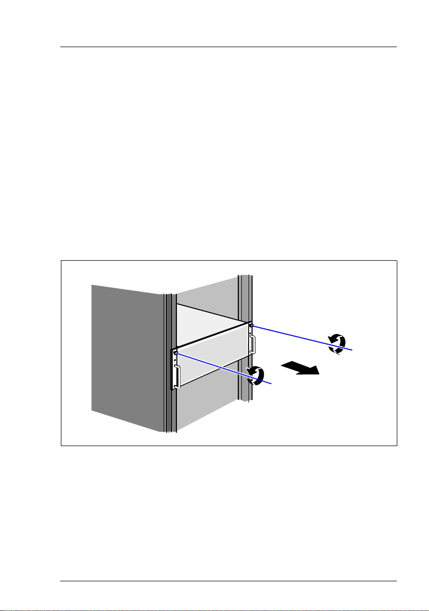
4.1 Opening the server
Figure 2: Removing the server
Ê Undo the knurled screws (1) and pull the server carefully out of the rack (2)
as far as possible.
Ê In the majority of cases it makes sense to remove the server from the rack.
I How to remove the server from the rack cabinet is described in the
operating manual.
RX600 S4 Options Guide 17
Page 18
Opening the server Preparation
2
1
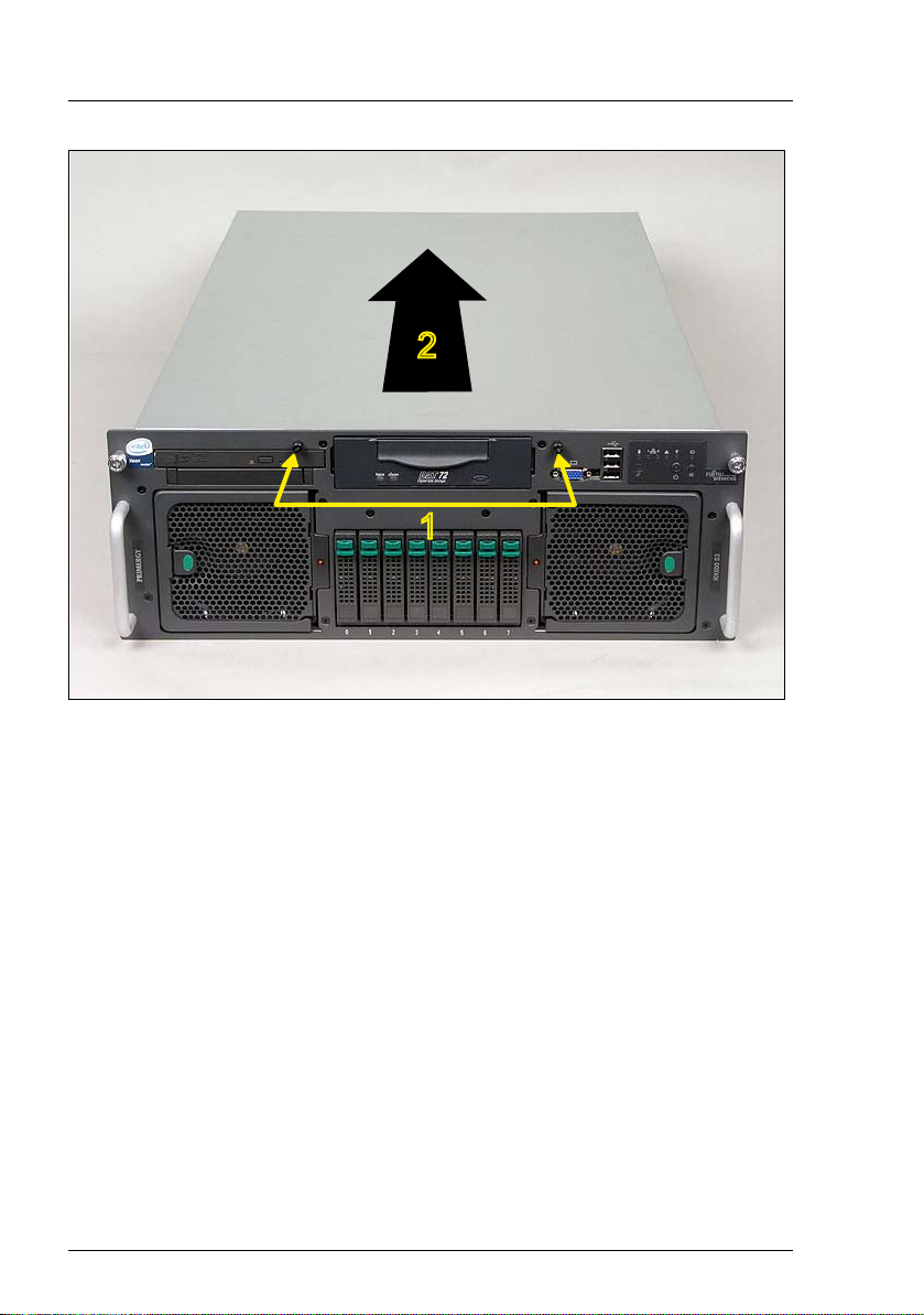
Figure 3: Removing the housing cover
Ê Undo the two captive screws on the front (1).
Ê Push the housing cover back a few centimeters (2).
Ê Take off the housing cover.
18 Options Guide RX600 S4
Page 19

5Main memory
V CAUTION!
Make sure you observe the safety notes in the chapter “Safety instruc-
tions” on page 11ff.
The system board provides slots for four memory boards, each of which can
accommodate up to eight memory modules.
The slots are suitable for DDR-II / 533 or 667 MHz FBDIMM modules with up to
8 Gbytes capacity per memory module, allowing a maximum memory configuration of 256 Gbytes.
I Due to the many and varied memory configuration options in the
RX600 S4, work on the memory boards should only be performed
by qualified engineers. The required procedure is therefore described
in the service supplement for this server.
RX600 S4 Options Guide 19
Page 20

Page 21

6 Processors
V CAUTION!
Make sure you observe the safety notes in the chapter “Safety instruc-
tions” on page 11ff.
Processors are components which are extremely sensitive to electrostatic discharge and must therefore be handled with caution.
After removing a processor from its protective wrapper or from a socket,
always place it on an insulated, antistatic surface and always with the
smooth side down.
Never slide a processor over a surface.
6.1 Installing additional processors
The system board can be upgraded to include up to four processors.
V CAUTION!
If you fit CPU sockets 2-4, you must observe the following:
1. If you install a total of two CPUs, you must use the CPU sockets of
CPU 1 and CPU 2.
2. If you install a total of three CPUs, you must use the CPU sockets of
CPU 1, CPU 2 and CPU 4 (not CPU 3!).
3. If you install a total of four CPUs, you must use the CPU sockets of
CPU 1 through CPU 4.
Always use processors of the same type. All processors must have the
same frequency and cache size. For multi-processor operation, you must
use a suitable multi-processor operating system.
Ê Open the server as described in the chapter “Preparation” on page 17f.
RX600 S4 Options Guide 21
Page 22

Installing additional processors Processors
Removing the processor cover
Figure 4: Removing the processor cover
Ê Hold the processor cover as shown in the figure above and lift it off.
22 Options Guide RX600 S4
Page 23

Processors Installing additional processors
Removing the dummy heat sink
CPU 1CPU 2CPU 3CPU 4
Figure 5: Heat sink dummies on the CPU sockets 2 - 4
Ê Remove the heat sink dummy from the relevant processor socket. To do this,
undo the four captive screws at the bottom of the dummy.
V ATTENTION!
Observe the fitting rules in section “Installing additional processors”
on page 21.
RX600 S4 Options Guide 23
Page 24

Installing additional processors Processors
Installing the processor
Figure 6: Opening the socket lever
Ê Release the socket lever by pressing it sideways ; then lift it up as far as it
will go.
Figure 7: Inserting the processor
V CAUTION!
The processor can only be installed in one direction. Note the marking
on one of the corners (see diagram above). To avoid damaging the pins,
do not force the processor into the socket.
Ê Position the new processor above the socket, and press it carefully into the
socket (1).
Ê Lock the processor into place in the socket by pushing the socket lever back
into its original position (2).
24 Options Guide RX600 S4
Page 25

Processors Installing additional processors
Installing the heat sink
V CAUTION!
Never install a processor without a heat sink, as the processor may
overheat, causing itself and the complete system board to fail.
Ê Carefully place the heat sink onto the processor.
I Make sure you do not touch or damage the thermal paste on the
underside of the heat sink.
Figure 8: Fastening the heat sink
Ê Fasten the heat sink with four screws. First fasten two diagonally opposite
screws, then the other two.
RX600 S4 Options Guide 25
Page 26

Installing additional processors Processors
Mounting the processor cover
Figure 9: Mounting the processor cover
Ê Reinstall the processor cover.
I Make sure the processor cover engages properly by pressing the
points marked "Memory" (see circles) on the cover.
Ê Close the server, plug in the power plugs, and switch on the server as
described in the chapter “Completion” on page 47f.
26 Options Guide RX600 S4
Page 27

Processors Replacing a processor
6.2 Replacing a processor
V CAUTION!
You may only use processors of the same type on the system board.
Ê Open the server as described in the chapter “Preparation” on page 17f.
Ê Remove the processor cover (see page 22)
Figure 10: Removing the heat sink
Ê Remove the four screws of the heat sink. First undo two diagonally opposite
screws, then the other two.
Ê Turn the heat sink carefully back and forth to loosen it. Then lift it out to
remove it.
RX600 S4 Options Guide 27
Page 28

Replacing a processor Processors
Ê Remove the residual thermal paste from the underside of the heat sink.
Ê Clean the underside of the heat sink using a lint-free cloth.
Figure 11: Removing the old processor
Ê Release the socket lever by pressing it sideways, and lift it up as far as it will
go (1).
Ê Lift the installed processor carefully out of its socket (2).
Installing the new processor
V CAUTION!
The processor can only be installed in one direction. Note the marking
on one of the corners (see diagram above). To avoid damaging the pins,
do not force the processor into the socket.
Figure 12: Installing the new processor
Ê Position the new processor above the socket, and press it carefully into the
socket (1).
Ê Lock the processor into place in the socket by pushing the socket lever back
into its original position (2).
Ê Carefully place the heat sink onto the processor.
28 Options Guide RX600 S4
Page 29

Processors Replacing a processor
I Make sure the thermal paste on the underside of the heat sink is not
damaged.
Ê Fasten the heat sink with four screws (see page 25). First fasten two diago-
nally opposite screws, then the other two.
Ê Reinstall the processor cover (see page 26).
Ê Close the server, plug in the power plugs, and switch on the server as
described in the chapter “Completion” on page 47f.
RX600 S4 Options Guide 29
Page 30

Page 31

7 Accessible drives
V CAUTION!
Make sure you observe the safety notes in the chapter “Safety instruc-
tions” on page 11ff.
The PRIMERGY RX600 S4 server offers a total of two bays for accessible
drives. You can install a tape drive and a CD/DVD drive.
7.1 Installing the CD/DVD drive
A B
Figure 13: CD/DVD drive with module frame
A CD/DVD drive (B) can be installed in the server. This drive is installed in the
server in a module frame (A).
Removing the module frame
The module frame for the CD/DVD drive is installed in the bay.
Ê Open the server as described in the chapter “Preparation” on page 17f.
RX600 S4 Options Guide 31
Page 32

Installing the CD/DVD drive Accessible drives
A
Figure 14: Removing the module frame
Ê Press the blue lever (A) and push the module frame forward out of the server.
Mounting a CD/DVD drive
A
B
Figure 15: Mounting the interface board
Ê Insert the interface board (B) into the opening (A) on the rear of the CD/DVD
drive housing.
32 Options Guide RX600 S4
Page 33

Accessible drives Installing the CD/DVD drive
Figure 16: Mounting the drive in its frame
Ê Place the CD/DVD drive in the frame such that it engages in the two
openings of the module frame (see circles).
Figure 17: The pre-mounted CD/DVD drive (back)
Ê Push the CD/DVD drive into its bay in the server from the front until it
engages.
RX600 S4 Options Guide 33
Page 34

Installing the CD/DVD drive Accessible drives
A
B
Figure 18: Connecting a CD/DVD drive
Ê Plug the power cable (A) and the data cable (B) into the interface board of
the CD/DVD drive.
Ê Close the server, plug in the power plugs, and switch on the server as
described in the chapter “Completion” on page 47f.
34 Options Guide RX600 S4
Page 35

Accessible drives Installing a tape drive
7.2 Installing a tape drive
A tape drive can be installed in the bay in the middle of the server. If no device
is installed in the bay, it contains only the module frame.
Removing the module frame
Ê Open the server as described in the chapter “Preparation” on page 17f.
B
A
A
Figure 19: Removing the module frame
Ê Press the two blue points on the spring clips on the module frame (A) and
push the module frame forward out of the server (B).
RX600 S4 Options Guide 35
Page 36

Installing a tape drive Accessible drives
Figure 20: Module frame with sliding rails
Ê Remove the two sliding rails attached to the sides by undoing the 4 screws.
V CAUTION!
Keep the module frame for future use. If you remove the drive without
installing a new one, you must reinstall the module frame to comply with
EMC regulations and to satisfy cooling requirements and fire protection
measures.
36 Options Guide RX600 S4
Page 37

Accessible drives Installing a tape drive
Figure 21: Fastening the sliding rails on the drive
Ê Fasten the two sliding rails on both sides of the drive to be installed using
two screws for each.
Figure 22: Inserting the tape drive
Ê Push the accessible drive into the empty bay as far as it will go, so that it slots
into place.
RX600 S4 Options Guide 37
Page 38

Installing a tape drive Accessible drives
Mounting the tape drive
A
B
Figure 23: Connecting the tape drive
Ê Connect the data cable (A) to the drive.
Ê Connect the power cable (B) to the drive.
38 Options Guide RX600 S4
Page 39

Accessible drives Installing a tape drive
Figure 24: Cable routing from the tape to the PCI controller
Ê Route the data cable as shown in figure 24.
Ê Connect the other end of the data cable to an unused connector on a PCI-
SCSI controller.
Ê Close the server, plug in the power plugs, and switch on the server as
described in the chapter “Completion” on page 47f.
RX600 S4 Options Guide 39
Page 40

Page 41

8 Controllers in non-hot-plug PCI
slots
V CAUTION!
Make sure you observe the safety notes in the chapter “Safety instruc-
tions” on page 11ff.
The system board has three non-hot-plug PCIe slots (slots 5 through 7), each
with a bandwidth of 2 GB/s and a mounting length of max. 315 mm.
When replacing/installing non-hot-pluggable components, you must proceed as
follows:
Ê Exit all applications and shut down the server properly.
Ê If your operating system has not switched off the server, press the On/Off
button.
Ê Unplug the power plugs from the grounded power outlets.
8.1 Installing controllers
Ê Open the server as described in the chapter “Preparation” on page 17f.
Ê Please read the documentation supplied with the PCI board.
Ê Plug any necessary cables into the PCI board.
Ê Remove the slot cover of the relevant slot on the back of the server.
I Keep the slot cover. If you remove a board, you must reinstall the slot
cover to comply with EMC (electromagnetic compatibility) regulations
and to satisfy cooling requirements and fire protection measures.
RX600 S4 Options Guide 41
Page 42

Installing controllers Controllers in non-hot-plug PCI slots
A
Figure 25: Installing a controller in a non-hot-plug PCI slot
Ê Insert the controller in the slot and press it in carefully. Close the locking
mechanism of the slot (A).
Ê If necessary, plug in the cables on the board and other components.
Ê Close the server, plug in the power plugs, and switch on the server as
described in the chapter “Completion” on page 47f.
42 Options Guide RX600 S4
Page 43

9 Battery for the RAID5 controller
V CAUTION!
Make sure you observe the safety notes in the chapter “Safety instruc-
tions” on page 11ff.
The iBBU (intelligent battery backup unit) is an intelligent battery for protecting
the data of the RAID5 controller in the event of power failure or voltage dips. The
data is saved for several hours.
9.1 Installing the battery (iBBU)
A
C
B
Figure 26: Components of the optional iBBU package
A Connection cable to the SAS riser card (not used with the RX600S4)
B Battery (iBBU)
C Screws for fastening the battery to the SAS riser card
Ê Open the server as described in the chapter “Preparation” on page 17f.
RX600 S4 Options Guide 43
Page 44
Installing the battery (iBBU) Battery for the RAID5 controlle
r
A
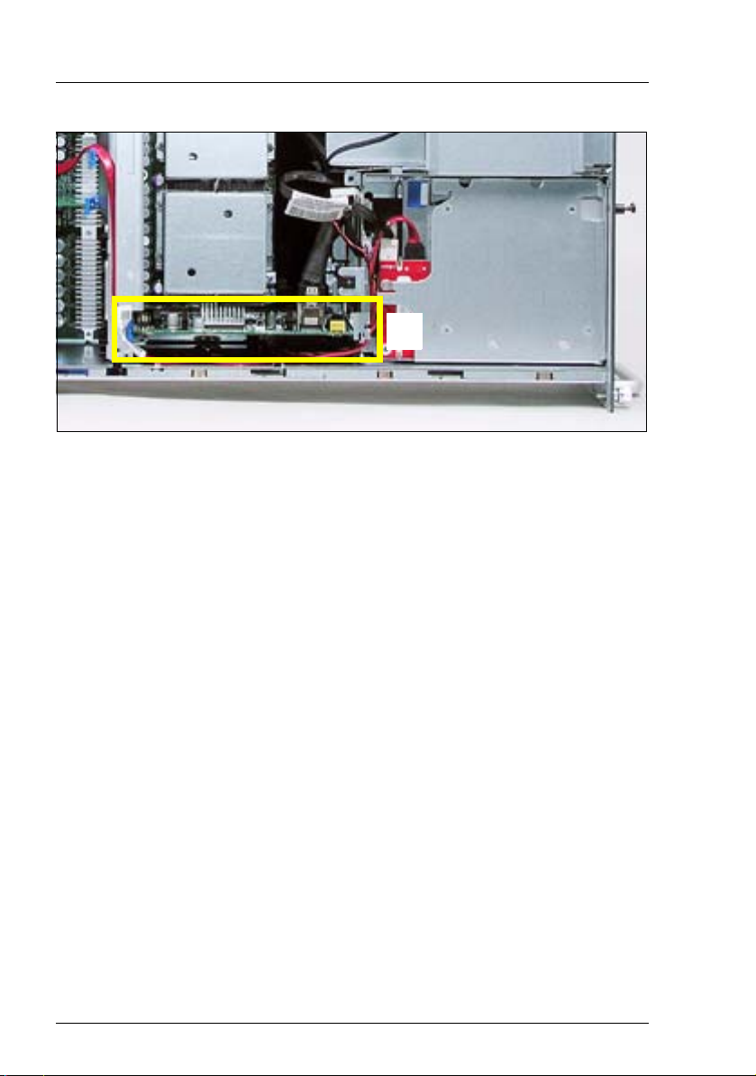
Figure 27: Position of the SAS riser card in the server
Ê Remove the SAS riser card (A) from the server.
Ê Place the SAS riser card on a suitable antistatic surface with the component
side facing down.
44 Options Guide RX600 S4
Page 45

Battery for the RAID5 controller Installing the battery (iBBU)
A
B
Figure 28: SAS riser card (top) and battery iBBU (bottom)
Ê Plug the connector (B) of the battery onto the connector (A) on the SAS riser
card.
Ê Fasten the battery to the SAS riser card with the three supplied screws.
Ê Close the server, plug in the power plugs, and switch on the server as
described in the chapter “Completion” on page 47f.
RX600 S4 Options Guide 45
Page 46

Page 47

10 Completion
V CAUTION!
Make sure you observe the safety notes in the chapter “Safety instruc-
tions” on page 11ff.
10.1 Closing the server
Figure 29: Mounting the housing cover
Ê Position the cover on the server in such a way that the rear edge protrudes
1-2 cm from the housing (see circle).
Ê Push the housing cover forward as far as possible.
Ê Fasten the housing cover to the front of the system with the two captive
screws (see page 18).
Ê Install the server in the rack.
I The relevant procedure is described in the operating manual.
Ê Fasten the server in the rack cabinet using the knurled screws.
Ê Plug in the power plugs and switch the server on.
RX600 S4 Options Guide 47
Page 48

Page 49

Abbreviations
The specialist terms and abbreviations listed here are not a complete list of all
common terms or abbreviations.
AC
Alternating Current
ACPI
Advanced Configuration and Power Interface
ANSI
American National Standards Institute
ASR&R
Automatic Server Reconfiguration and Restart
BBU
Battery Backup Unit
BIOS
Basic Input-Output System
BMC
Baseboard Management Controller
BTU
British Thermal Unit
CC
Cache Coherency
CD-ROM
Compact Disk-Read Only Memory
CHS
Cylinder Head Sector
CMOS
Complementary Metal Oxide Semiconductor
RX600 S4 Options Guide 49
Page 50

Abbreviations
COM
Communications
CPU
Central Processing Unit
DC
Direct Current
DIMM
Dual Inline Memory Module
DIP
Dual Inline Package
DMA
Direct Memory Access
DMI
Desktop Management Interface
DVD
Digital Versatile Disk
ECC
Errror Checking and Correcting
ECP
Extended Capabilities Port
EEPROM
Electrically Erasable Programmable Read-Only Memory
EFI
Extensible Firmware Interface
EIA
Electronic Industries Alliance
EMC
Electromagnetic Compatibility
50 Options Guide RX600 S4
Page 51

EMP
Emergency Management Port
EPP
Enhanced Parallel Port
EPROM
Erasable Programmable Read-Only Memory
ESD
ElectroStatic Discharge
FAT
File Allocation Table
FPC
Front Panel Controller
FRU
Field Replaceable Unit
FSB
Front Side Bus
Abbreviations
GAM
Global Array Manager
GUI
Graphical User Interface
HDD
Hard Disk Drive
HSC
Hot-Swap Controller
HU
Height Unit
I²C
Inter-Integrated Circuit
RX600 S4 Options Guide 51
Page 52

Abbreviations
I/O
Input/Output
iBBU
Intelligent Battery Backup Unit
ICM
Intelligent Chassis Management
ID
Identification
IDE
Integrated Drive Electronics
IEC
International Electrotechnical Commission
IME
Integrated Mirroring Enhanced
IPMB
Intelligent Platform Management Bus
IPMI
Intelligent Platform Management Interface
IRMC
Intelligent Remote Management Controller
IRQ
Interrupt Request Line
LAN
Local Area Network
LBA
Logical Block Address
LCD
Liquid Crystal Display
52 Options Guide RX600 S4
Page 53

LED
Light Emitting Diode
LP
Low Profile
LUN
Logical Unit Number
LV D
Low-Voltage Differential SCSI
MMF
Multi Mode Faser
MRL
Manual Retention Latch
NMI
Non Maskable Interrupt
NTFS
New Technology File System
Abbreviations
NVRAM
Non Volatile Random Access Memory
OS
Operating System
PAM
Promise Array Management
PCI
Peripheral Component Interconnect
PDA
Prefailure Detection and Analysing
PDF
Portable Data Format
RX600 S4 Options Guide 53
Page 54

Abbreviations
PFD
Prefailure Detection (ServerView)
POST
Power-On Self Test
PS/2
Personal System/2
RAID
Redundant Array of Independent Disks
RAM
Random Access Memory
RoHS
Restriction of the Use of Certain Hazardous Substances (Waste from
Electric and Electronic Equipment, EU Directive)
ROM
Read-Only Memory
RoMB
RAID on Motherboard
RSB
Remote Service Board
RTC
Real Time Clock
RTDS
Remote Test and Diagnostic System
SAF-TE
SCSI Accessed Fault-Tolerance Enclosures
SAS
Serial Attached SCSI
SATA
Serial Advanced Technology Attachment
54 Options Guide RX600 S4
Page 55

SBE
Single-Bit Error
SCA
Single-Connector Attachment
SCSI
Small Computer System Interface
SCU
System Configuration Utility
SDR
Sensor Data Record
SDRAM
Synchronous Dynamic Random Access Memory
SEL
System Event Log
S.M.A.R.T
Self-Monitoring, Analysis, and Reporting Technology
Abbreviations
SMI
System Management Interrupt
SSU
System Setup Utility
SVGA
Super Video Graphics Adapter
USB
Universal Serial Bus
VGA
Video Graphics Adapter
VRD
Voltage Regulator Down
RX600 S4 Options Guide 55
Page 56

Abbreviations
VRM
Voltage Regulator Module
WEEE
Waste from Electric and Electronic Equipment (EU Directive)
WOL
Wakeup on LAN
56 Options Guide RX600 S4
Page 57

Index
A
accessible drives, add 7
add
accessible drives 7
battery for RAID5 controller 43
CD/DVD drive 31
controller 41
iBBU 43
main memory 7
non-hot-plug PCI controllers 41
processor 21
additional documentation 6
B
battery for RAID5 controller, add 43
BMC 8
C
CD/DVD drive, add 31
controllers, add 7, 41
E
ESD (devices sensitive to electrostatic
discharge) 15
H
heat sink
fasten 25
remove 27
remove dummy 23
housing cover
mount 47
remove 18
I
I/O riser 8
iBBU, add 43
Information material for the server 6
intelligent battery backup unit 43
iRMC S2 8
L
laser information 15
light-emitting diode (LED) 15
lithium battery 14
M
main memory, add 7
module frame
for CD/DVD drive 31
for tape drives 36
multi-processor operating system 21
multi-processor operation 21
N
non-hot-plug PCI controllers, add 41
notational conventions 8
P
PCI slots
hot-plug 7
non-hot-plug 7
processor
add 7, 21
install 24
installation rules 21
multi-processor operation 21
remove dummy heat sink 23
replace 27
processor cover
mount 26
remove 22
R
RAID5 7
RAID5 controller 7
add battery 43
Remote Management 8
remove
housing cover 18
replace
processor 27
RX600 S4 Options Guide 57
Page 58

 Loading...