

Page 1

PRIMERGY RX200 S5 Server
Options Guide
Edition April 2009
Page 2

Comments… Suggestions… Corrections…
The User Documentation Department would like to
know your opinion of this manual. Your feedback helps
us optimize our documentation to suit your individual
needs.
Feel free to send us your comments by e-mail to
manuals@ts.fujitsu.com.
Certified documentation
according to DIN EN ISO 9001:2000
To ensure a consistently high quality standard and
user-friendliness, this documentation was created to
meet the regulations of a quality management system
which complies with the requirements of the standard
DIN EN ISO 9001:2000.
cognitas. Gesellschaft für Technik-Dokumentation mbH
www.cognitas.de
Copyright and Trademarks
Copyright © 2009 Fujitsu Technology Solutions GmbH.
All rights reserved.
Delivery subject to availability; right of technical modifications reserved.
All hardware and software names used are trademarks of their respective manufacturers.
Page 3

Contents
1 Preface . . . . . . . . . . . . . . . . . . . . . . . . . . . . . . 5
1.1 Concept and target groups . . . . . . . . . . . . . . . . . . . 5
1.2 Documentation overview . . . . . . . . . . . . . . . . . . . . 5
1.3 Expansions and conversions . . . . . . . . . . . . . . . . . . 7
1.4 Notational conventions . . . . . . . . . . . . . . . . . . . . . 9
2 Procedure . . . . . . . . . . . . . . . . . . . . . . . . . . . . 11
3 Safety instructions . . . . . . . . . . . . . . . . . . . . . . . 13
4 Preparation . . . . . . . . . . . . . . . . . . . . . . . . . . . 19
4.1 Pulling out/removing the server . . . . . . . . . . . . . . . . 19
4.2 Opening the server . . . . . . . . . . . . . . . . . . . . . . . 20
4.3 Removing the air cowl . . . . . . . . . . . . . . . . . . . . . 22
5 Processors . . . . . . . . . . . . . . . . . . . . . . . . . . . 23
5.1 Installing a second processor . . . . . . . . . . . . . . . . . 23
5.2 Replacing the processor . . . . . . . . . . . . . . . . . . . . 26
5.3 Replacing the heat sink . . . . . . . . . . . . . . . . . . . . 29
6 Main memory . . . . . . . . . . . . . . . . . . . . . . . . . . 31
6.1 Equipping rules . . . . . . . . . . . . . . . . . . . . . . . . . 32
6.2 Extending/replacing the main memory . . . . . . . . . . . . 34
7 Accessible drive . . . . . . . . . . . . . . . . . . . . . . . . 37
RX200 S5 Operating Manual
Page 4

Contents
7.1 Installing a SATA DVD drive . . . . . . . . . . . . . . . . . . . 38
8 HDD modules . . . . . . . . . . . . . . . . . . . . . . . . . . 41
9 Expansion cards and iBBU . . . . . . . . . . . . . . . . . . . 47
9.1 Installing an expansion card in riser cards . . . . . . . . . . 47
9.2 Installing a modular RAID controller . . . . . . . . . . . . . . 51
9.3 Installing an iBBU . . . . . . . . . . . . . . . . . . . . . . . . 52
10 USB solid state disk (uSSD) . . . . . . . . . . . . . . . . . . 57
11 Trusted Platform Module (TPM) . . . . . . . . . . . . . . . . . 59
12 Completion . . . . . . . . . . . . . . . . . . . . . . . . . . . . 61
12.1 Fitting the air cowl . . . . . . . . . . . . . . . . . . . . . . . . 61
12.2 Closing the server . . . . . . . . . . . . . . . . . . . . . . . . 65
13 Cabling . . . . . . . . . . . . . . . . . . . . . . . . . . . . . . 67
13.1 Cabling overview . . . . . . . . . . . . . . . . . . . . . . . . 67
13.2 Cable diagrams . . . . . . . . . . . . . . . . . . . . . . . . . 68
13.2.1 Cabling for up to 4 HDD modules . . . . . . . . . . . . . . . . 68
13.2.2 Cabling for up to 6 HDD modules . . . . . . . . . . . . . . . . . 69
13.2.3 Cabling for up to 8 HDD modules . . . . . . . . . . . . . . . . . 70
Index . . . . . . . . . . . . . . . . . . . . . . . . . . . . . . . . . . . . 71
Operating Manual RX200 S5
Page 5

1 Preface
The PRIMERGY RX200 S5 server is an Intel-based server for mid-size
networks and large companies. The server is suitable for use as a file server
and also as an application, information or Internet server.
Thanks to its highly developed hardware and software components, the
PRIMERGY RX200 S5 server offers a high level of data security and availability.
These components include hot-plug hard disk drive modules, redundant system
fans and power supply units, the Server Management ServerView Suite,
Prefailure Detection and Analysis (PDA) and Automatic Server Reconfiguration
and Restart (ASR&R).
Security functions in the BIOS Setup and on the system board protect the data
on the server against manipulation. Additional security is provided by the
lockable rack door.
The server occupies one height unit in the rack.
1.1 Concept and target groups
This Options Guide shows you how to extend and upgrade your server.
V CAUTION!
The activities described in this manual may only be performed by
technical specialists.
I The installation and removal of the hot-plug components is described in
the Operating Manual supplied with the server.
1.2 Documentation overview
More information on your PRIMERGY RX200 S5 can be found in the following
documents:
– “Quick Start Hardware - PRIMERGY RX200 S5” leaflet (only included as a
printed copy)
– “Quick Start Software - Quick Installation Guide” DVD booklet (only included
with the PRIMERGY ServerView Suite as a printed copy)
– “Safety notes and other important information” manual
RX200 S5 Options Guide 5
Page 6

Documentation overview Preface
– “Warranty” manual
– “PRIMERGY ServerView Suite Local Service Concept - LSC” manual
– “Returning used devices” manual
– “Helpdesk” leaflet
– Technical manual for the system board D2786
– “PRIMERGY RX200 S5 Server Operating Manual”
– "D2786 BIOS Setup Utility for RX200 S5" manual
I PRIMERGY manuals are available in PDF format on the PRIMERGY
ServerView Suite DVD 2. The PRIMERGY ServerView Suite DVD 2 is
part of the PRIMERGY ServerView Suite supplied with every server.
If you no longer have the ServerView Suite DVDs, you can obtain the
relevant current versions using the order number U15000-C289.
The PDF files of the manuals can also be downloaded free of charge
from the Internet. The overview page showing the online documentation
available on the Internet can be found using the URL:
http://manuals.ts.fujitsu.com. The PRIMERGY server documentation can
be accessed using the Industry standard servers navigation option.
Further sources of information:
– PRIMERGY Abbreviations and Glossary on the PRIMERGY
ServerView Suite DVD 2
– Manual for the monitor
– Documentation for the boards and drives
– Operating system documentation
– Information files in your operating system
6 Options Guide RX200 S5
Page 7

Preface Expansions and conversions
1.3 Expansions and conversions
Second processor
The system board can be upgraded with a second processor. Only processors
of the same type may be used on the system board. The second processor must
have the same clock frequency as the first.
Main memory expansion
The system board supports up to 96 GB of main memory. 6 slots (2 banks with
3 channels each) are provided for each CPU for the main memory.
Accessible drive
In the version with a maximum of six HDD modules, a 5.25 inch bay is available
for a DVD drive (SATA interface) with a height of 0.5 inches.
Extending the number of HDD modules
You can add further HDD modules, if required. The server can accommodate a
maximum of eight HDD modules. To do this, you may need to exchange the
HDD backplane.
Expansion cards in the PCI slots
The system board offers two slots with a PCI Express x8 interface and one slot
with a PCI Express x4 interface (exclusively for modular RAID controllers):
Expansion cards can only be installed using three-slot riser cards. The riser
cards provide three slots at a right angle to the system board (two slots for PCIe
controllers and one slot for a RAID controller).
Intelligent Battery Backup Unit
You can add an iBBU (intelligent Battery Backup Unit) to the optional modular
RAID controller to ensure data integrity in the event of a power failure.
uSSD
You can insert a USB solid state disk on the system board at a later time.
RX200 S5 Options Guide 7
Page 8

Expansions and conversions Preface
TPM
A Trusted Platform Module (TPM) for safer storage of keys can be implemented
as an option. This module enables programs from third party manufacturers to
store key information (e.g. drive encryption using Windows Bitlocker Drive
Encryption).
The TPM is activated via the BIOS system (for more information, refer to the
Fujitsu Technology Solutions BIOS manual).
V CAUTION!
– When using the TPM, note the program descriptions provided by the
third party manufacturers.
– You must also create a backup of the TPM content. To do this, follow
the third party manufacturer's instructions. Without this backup, if the
TPM or the system board is faulty you will not be able to access your
data.
– If a failure occurs, please inform your service about the TPM
activation before it takes any action, and be prepared to provide them
with your backup copies of the TPM content.
8 Options Guide RX200 S5
Page 9
Preface Notational conventions
1.4 Notational conventions
The following notational conventions are used in this manual:
Text in italics indicates commands or menu items.
“Quotation marks” indicate names of chapters and terms that are being
emphasized.
Ê describes activities that must be performed in the order
shown.
V CAUTION! pay particular attention to texts marked with this symbol.
Failure to observe this warning may endanger your life,
destroy the system or lead to the loss of data.
I indicates additional information, notes and tips.
RX200 S5 Options Guide 9
Page 10

Page 11

2Procedure
V CAUTION!
● The actions described in this manual should only be performed by
technical specialists.
● Repairs to the device that do not relate to CSS failures must only be
carried out by service personnel. Please note that unauthorized interference with the system will void the warranty and exempt the
manufacturer from all liability.
● Any failure to observe the guidelines in this manual, and any improper
repairs could expose the user to risks (electric shock, energy
hazards, fire hazards) or damage the equipment.
Ê First of all, carefully read the safety instructions in the chapter “Safety
instructions” on page 13 et seq..
Ê Make sure that all necessary manuals (see the section “Documentation
overview” on page 5) are available; print the PDF files if required. Most
importantly, you will need the operating manual for the server and the
technical manual for the system board.
Ê Shut the server down correctly, switch it off, disconnect the power plugs and
open the server as described in the chapter “Preparation” on page 19 et
seq..
Ê Carry out the expansion or upgrade of your server as described in the
pertinent chapter.
I Installation and removal of the hot-plug components are described in
the operating manual.
Ê Close the server, connect it to the power outlet, and switch it on as described
in the chapter “Completion” on page 61 et seq..
Ê Start the operating system and make the appropriate configuration if
necessary (see the operating manual).
RX200 S5 Options Guide 11
Page 12

Page 13

3 Safety instructions
I The following safety instructions are also provided in the manual “Safety
notes and other important information”.
This device meets the relevant safety regulations for IT equipment. If you have
any questions about whether you can install the server in the intended
environment, please contact your sales outlet or our customer service team.
V CAUTION!
● The actions described in this manual should only be performed by
technical specialists.
● Repairs to the device that do not relate to CSS failures must only be
carried out by service personnel. Please note that unauthorized interference with the system will void the warranty and exempt the
manufacturer from all liability.
● Any failure to observe the guidelines in this manual, and any improper
repairs could expose the user to risks (electric shock, energy
hazards, fire hazards) or damage the equipment.
RX200 S5 Options Guide 13
Page 14

Safety instructions
Before starting up
V CAUTION!
● During installation and before operating the device, observe the
instructions on environmental conditions for your device.
● If the device is brought in from a cold environment, condensation may
form both inside and on the outside of the device.
Wait until the device has acclimatized to room temperature and is
absolutely dry before starting it up. Material damage may be caused
to the device if this requirement is not observed.
● Transport the device only in the original packaging or in packaging
that protects it from knocks and jolts.
Installation and operation
V CAUTION!
● This unit should not be operated in ambient temperatures above
35 °C.
● If the unit is integrated into an installation that draws power from an
industrial power supply network with an IEC309 connector, the power
supply's fuse protection must comply with the requirements for nonindustrial power supply networks for type A connectors.
● The unit automatically adjusts itself to a mains voltage in a range of
100 V - 127 V oder 200 V - 240 V. Ensure that the local mains
voltage lies within these limits.
● This device must only be connected to properly grounded shock-
proof sockets or insulated sockets of the rack's internal power supply
with tested and approved power cables.
● Ensure that the device is connected to a grounded shockproof socket
close to the device.
14 Options Guide RX200 S5
Page 15

Safety instructions
V CAUTION!
● Ensure that the power sockets on the device and the grounded shock-
proof sockets are freely accessible.
● The On/Off button or the main power switch (if present) does not
isolate the device from the mains power supply. To disconnect it
completely from the mains power supply, unplug all network power
plugs from the grounded shockproof sockets.
● Always connect the server and the attached peripherals to the same
power circuit. Otherwise you run the risk of losing data if, for example,
the server is still running but a peripheral device (e.g. memory
subsystem) fails during a power outage.
● Data cables must be adequately shielded.
● The EN 50173 and EN 50174-1/2 standards apply for LAN cabling.
The minimum requirement is the use of a category 5 screened LAN
cable for 10/100 Mbit/s Ethernet, or a category 5e cable for Gigabit
Ethernet. The requirements from the ISO/IEC 11801 specification
must also be met.
● Route the cables in such a way that they do not create a potential
hazard (make sure no-one can trip over them) and that they cannot
be damaged. When connecting the server, refer to the relevant
instructions in this manual.
● Never connect or disconnect data transmission lines during a storm
(risk of lightning strike).
● Make sure that no objects (e.g. jewelry, paperclips etc.) or liquids can
get inside the server (risk of electric shock, short circuit).
● In emergencies (e.g. damaged casing, controls or cables, penetration
of liquids or foreign bodies), switch off the server immediately, remove
all power plugs and contact your sales outlet or customer service
team.
RX200 S5 Options Guide 15
Page 16

Safety instructions
V CAUTION!
● Proper operation of the system (in accordance with IEC 60950-1/
EN 60950-1) is only ensured if the casing is completely assembled
and the rear covers for the installation slots have been fitted (electric
shock, cooling, fire protection, interference suppression).
● Only install system expansions that satisfy the requirements and
rules governing safety and electromagnetic compatibility and those
relating to telecommunication terminals. If you install other expansions, they may damage the system or violate the safety regulations.
Information on which system expansions are approved for installation
can be obtained from our customer service center or your sales
outlet.
● The components marked with a warning notice (e.g. lightning symbol)
may only be opened, removed or exchanged by authorized, qualified
personnel. Exception: CCS components can be replaced.
● The warranty is void if the server is damaged during installation or
replacement of system expansions.
● Only set screen resolutions and refresh rates that are specified in the
operating manual for the monitor. Otherwise, you may damage your
monitor. If you are in any doubt, contact your sales outlet or customer
service center.
Batteries
V CAUTION!
● Incorrect replacement of batteries may result in a risk of explosion.
The batteries may only be replaced with identical batteries or with a
type recommended by the manufacturer (see the technical manual for
the system board).
● Replace the lithium-battery on the system board in accordance with
the instructions in the technical manual for the system board.
16 Options Guide RX200 S5
Page 17

Safety instructions
Working with CDs/DVDs and CD/DVD drives
When working with devices with CD/DVD drives, these instructions must be
followed.
V CAUTION!
● Only use CDs/DVDs that are in perfect condition in your server's
CD/DVD drive, in order to prevent data loss, equipment damage and
injury.
● Check each CD/DVD for damage, cracks, breakages etc. before
inserting it in the drive.
Note that any additional labels applied may change the mechanical
properties of a CD/DVD and cause imbalance.
Damaged and imbalanced CDs/DVDs can break at high drive speeds
(data loss).
Under certain circumstances, sharp CD/DVD fragments can pierce
the cover of the CD/DVD drive (equipment damage) and can fly out
of the device (danger of injury, particularly to uncovered body parts
such as the face or neck).
I You can prevent mechanical damage and damage to the CD/DVD drive,
as well as premature CD/DVD wear, by observing the following suggestions:
– Only insert CDs/DVDs in the drive when needed and remove them
after use.
– Store the CDs/DVDs in suitable sleeves.
– Protect the CDs/DVDs from exposure to heat and direct sunlight.
Laser information
The CD/DVD drive complies with IEC 60825-1 laser class 1.
V CAUTION!
The CD/DVD drive contains a light-emitting diode (LED), which under
certain circumstances produces a laser beam stronger than laser
class 1. Looking directly at this beam is dangerous.
Never remove parts of the CD/DVD drive casing!
RX200 S5 Options Guide 17
Page 18
Safety instructions
Modules with electrostatic-sensitive components
Systems and components that might be damaged by electrostatic discharge
(ESD) are marked with the following label:
Figure 1: ESD label
When you handle components fitted with ESDs, you must observe the following
points under all circumstances:
● Remove the power plug before installing or removing components
containing ESDs.
● You must always discharge yourself of static charges (e.g. by touching a
grounded object) before working.
● The equipment and tools you use must be free of static charges.
● Only touch the components at the positions highlighted in green (touch
points).
● Do not touch any exposed pins or conductors on a component.
● Use a grounding cable designed for this purpose to connect yourself to the
system unit as you install components.
● Place all components on a static-safe base.
I You will find a detailed description for handling ESD components in the
relevant European or international standards (DIN EN 61340-5-1,
ANSI/ESD S20.20).
18 Options Guide RX200 S5
Page 19

4 Preparation
V CAUTION!
Follow the safety instructions in the chapter “Safety instructions” on
page 13.
4.1 Pulling out/removing the server
Ê Terminate all applications and shut down the server correctly.
Ê If your operating system has not switched off the server, press the on/off
button.
Ê Pull all power connectors out of the power outlets.
Ê Loosen the knurled screws on the sides and pull the server carefully out of
the rack as far as it will go.
I If the server is not easily accessible once it has been pulled out,
remove it from the rack completely. See the operating manual for
details on how to remove the server from the rack.
V CAUTION!
At least two people are needed to remove the server from the rack.
RX200 S5 Options Guide 19
Page 20
Opening the server Preparation
4.2 Opening the server
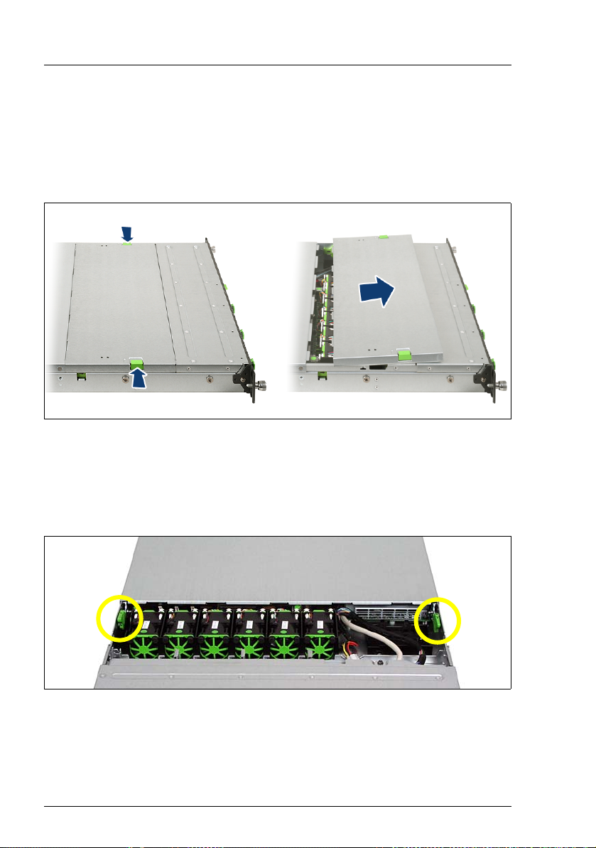
You must remove the fan cover before removing the housing cover.
Removing the fan cover
1
2
1
Figure 2: Opening the fan cover
Ê Push the two green buttons (1) in the direction of the arrow and lift the fan
cover upwards to remove it (2).
Removing the housing cover
Figure 3: Removing the housing cover
Ê Use the two green locking levers (see circles) to unlock the housing cover.
20 Options Guide RX200 S5
Page 21
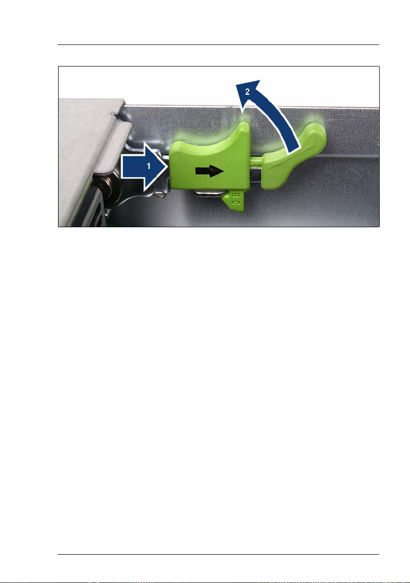
Preparation Opening the server
Figure 4: Using the locking levers
Ê Push the green locking levers together as shown (1) and then move them
up (2) so that the housing cover is pushed backward slightly.
Ê Lift off the housing cover upwards.
RX200 S5 Options Guide 21
Page 22
Removing the air cowl Preparation
4.3 Removing the air cowl
Figure 5: Taking off the air cowl
Ê Lift the air cowl upwards to remove it.
22 Options Guide RX200 S5
Page 23

5 Processors
V CAUTION!
Follow the safety instructions in the chapter “Safety instructions” on
page 13.
V CAUTION!
Processors are modules which can react extremely sensitively to electrostatic discharges and which must therefore always be handled with care.
After a processor has been removed from its protective sleeve or from its
socket, place it with its smooth side down on a non-conducting, antistatic
surface.
Never push a processor over a surface.
5.1 Installing a second processor
The system board can be upgraded with a second processor.
V CAUTION!
Only processors of the same type may be used on the system board. The
second processor must have the same clock frequency as the first. For
dual operation, use a suitable multiprocessor operating system.
Ê Open the server as described in chapter “Preparation” on page 19.
Ê Lift the air cowl upwards to remove it as described in section “Removing the
air cowl” on page 22.
RX200 S5 Options Guide 23
Page 24

Installing a second processor Processors
Inserting the processor
2
3
1
Figure 6: Releasing the lever
Ê Release the socket lever by pressing it sideways and pushing it upwards as
far as it will go (1).
Ê Open the cover (2).
Ê Remove the plastic cover (3).
2
3
1
Figure 7: Inserting the processor
Ê Position the new processor over the socket and then place it carefully into
the socket (1).
V CAUTION!
The processor can only be installed in one particular direction. Note
the marking on one of the corners. To avoid damaging the processor,
do not force it into the socket.
Ê Close the cover (2).
Ê Lock the processor in place in the socket by returning the socket lever to its
original position (3).
24 Options Guide RX200 S5
Page 25

Processors Installing a second processor
Installing the heat sink
Figure 8: Installing the heat sink
Ê Place the heat sink on the processor as shown.
Ê Fasten the heat sink by tightening the four screws in a crossover pattern (see
circles).
V CAUTION!
Never install a processor without a heat sink as otherwise the processor
may overheat, causing the possible failure of the processor and system
board.
Ê Fit the air cowl as described in chapter “Completion” on page 61.
Ê Close the server, connect all power plugs to the power outlets, and switch on
the server as described in chapter “Completion” on page 61.
RX200 S5 Options Guide 25
Page 26

Replacing the processor Processors
5.2 Replacing the processor
V CAUTION!
Only processors of the same type may be used on the system board.
Ê Open the server as described in chapter “Preparation” on page 19.
Ê Lift the air cowl upwards to remove it as described in section “Removing the
air cowl” on page 22.
Figure 9: Removing the heat sink
Ê Loosen the four screws of the heat sink in a crossover pattern.
Ê Loosen the heat sink carefully by turning it back and forth. Then lift it up and
off.
Ê Remove the residual thermal paste from the underside of the heat sink.
Ê Clean the underside of the heat sink using a lint-free cloth.
26 Options Guide RX200 S5
Page 27

Processors Replacing the processor
2
3
1
Figure 10: Removing an old processor
Ê Release the socket lever by pressing it sideways and pull it upward as far as
it will go (1).
Ê Open the cover (2).
Ê Lift the installed processor carefully out of the socket (3).
2
3
1
Figure 11: Inserting a new processor
Ê Position the new processor over the socket and then place it carefully into
the socket (1).
V CAUTION!
The processor can only be installed in one particular direction. Note
the marking on one of the corners. To avoid damaging the processor,
do not force it into the socket.
Ê Close the cover (2).
Ê Lock the processor in place in the socket by returning the socket lever to its
original position (3).
RX200 S5 Options Guide 27
Page 28

Replacing the processor Processors
Ê Apply a small amount of thermal paste to the upper side of the new
processor.
Ê Ensure a thin and even distribution of the thermal paste.
Ê Place the heat sink on the processor (see figure 8 on page 25).
Ê Fasten the heat sink by tightening the four screws in a crossover pattern.
Ê Fit the air cowl as described in chapter “Completion” on page 61.
Ê Close the server, connect all power plugs to the power outlets, and switch on
the server as described in chapter “Completion” on page 61.
28 Options Guide RX200 S5
Page 29

Processors Replacing the heat sin
k
5.3 Replacing the heat sink
Ê Open the server as described in chapter “Preparation” on page 19.
Ê Lift the air cowl upwards to remove it as described in section “Removing the
air cowl” on page 22.
Ê Remove the four screws of the heat sink in a crossover pattern (see figure 9
on page 26).
Ê Loosen the heat sink carefully by turning it back and forth. Then lift it up and
off.
Ê Clean the upper side of the processor using a lint-free cloth.
I New heat sinks come with thermal paste already applied. When reusing
used heat sinks, you need to apply thermal paste.
Ê Place the heat sink on the processor (see figure 8 on page 25).
Ê Fasten the heat sink by tightening the four screws in a crossover pattern (see
figure 8 on page 25).
Ê Fit the air cowl as described in chapter “Completion” on page 61.
Ê Close the server, connect all power plugs to the power outlets, and switch on
the server as described in chapter “Completion” on page 61.
RX200 S5 Options Guide 29
Page 30

Page 31

6Main memory
V CAUTION!
Follow the safety instructions in the chapter “Safety instructions” on
page 13.
The system board has a total of 12 slots (6 for each CPU) for memory modules
(DIMMs), which are suitable for both RDIMM memory modules (registered
DIMM with the capacities 2048, 4096 and 8192 MB) and UDIMM memory
modules (unbuffered DIMM with the capacities 1024 and 2048 MB).
The board supports a maximum memory configuration of 24 GB for UDIMM
memory modules and 96 GB for RDIMM memory modules. A mixture of these
two module types is not permitted.
The SDDC function (Single Device Data Correction or Chipkill) is only
supported for RDIMM memory modules.
RX200 S5 Options Guide 31
Page 32

Equipping rules Main memory
6.1 Equipping rules
The 6 slots for each CPU for the main memory are divided into two banks (bank
1 and bank 2) with 3 channels each (A, B and C).
Independent
Channel Mode
DIMM 1C
DIMM 2C
DIMM 1B
DIMM 2B
DIMM 1A
DIMM 2A
CPU2
CPU 1
Legend:
required
required, if 2nd CPU is configured
optional, same type in bank per CPU
optional, any type
not used
CPU1
CPU 2
DIMM 2D
DIMM 1D
DIMM 2E
DIMM 1E
DIMM 2F
DIMM 1F
Mirrored
Channel Mode
DIMM 1C
DIMM 2C
DIMM 1B
DIMM 2B
DIMM 1A
DIMM 2A
CPU2
CPU 1
CPU1
CPU 2
DIMM 2D
DIMM 1D
DIMM 2E
DIMM 1E
DIMM 2F
DIMM 1F
Performance
Channel Mode
DIMM 1C
DIMM 2C
DIMM 1B
DIMM 2B
DIMM 1A
DIMM 2A
CPU2
CPU 1
CPU1
CPU 2
DIMM 2D
DIMM 1D
DIMM 2E
DIMM 1E
DIMM 2F
DIMM 1F
Spare
Channel Mode
DIMM 1C
DIMM 2C
DIMM 1B
DIMM 2B
DIMM 1A
DIMM 2A
CPU2
CPU 1
CPU1
CPU 2
DIMM 2D
DIMM 1D
DIMM 2E
DIMM 1E
DIMM 2F
DIMM 1F
Figure 12: Equipping the main memory in the different modes
Independent Channel Mode
– Allows all channels to be equipped in any order.
– Works with DIMMs of different clock frequencies and sets them at the lowest
frequency.
– Works with both UDIMM memory modules and RDIMM memory modules.
Mirrored Channel Mode
– Requires identical modules on channels A & B (1st CPU) and on C & D (2nd
CPU).
– Half of the capacity is used for mirroring – the available memory for applica-
tions amounts to just half of the installed memory.
– Channel C (1st CPU) or channel F (2nd CPU) are not available in this mode.
– RDIMM memory modules are supported.
32 Options Guide RX200 S5
Page 33

Main memory Equipping rules
Performance Channel Mode
– Requires identical modules on all channels of each bank for each CPU.
– RDIMM memory modules are supported.
Spare Channel Mode
– Requires identical modules on all channels of each bank for each CPU.
– One-third of the capacity is used as a spare area – this reduces the usable
memory for applications to two-thirds.
– RDIMM memory modules are supported.
Notes on equipping
– Equipping always starts at DIMM slot 1A.
– The minimum memory configuration is 1 DIMM per system board in
Independent Channel Mode.
– Memory modules with different clock rates may be mixed. The system
automatically adjusts itself to the lowest clock rate.
– The greater the capacity of the memory module, the further away from the
CPU it must be equipped. This applies for each channel.
– Single and dual ranked memory modules may be mixed. Quad ranked
memory modules, on the other hand, must be used exclusively.
– In mirror mode and in spare mode, memory modules of different capacities
may be mixed on a bank by bank basis (2x2, see figure "Equipping the main
memory in the different modes" on page 32).
– The assignment of the DIMM slots to the memory banks and channels is
imprinted on the system board next to the DIMM slots.
RX200 S5 Options Guide 33
Page 34

Extending/replacing the main memory Main memory
6.2 Extending/replacing the main memory
Ê Open the server as described in chapter “Preparation” on page 19.
Ê Lift the air cowl upwards to remove it as described in section “Removing the
air cowl” on page 22.
Removing installed memory modules
2
1
1
Figure 13: Removing a memory module
Ê Fold the ejection levers outwards on both sides of the corresponding slot (1).
This will cause the memory module installed in the slot to be ejected.
Ê If the slot was already equipped: Remove the memory module (2).
34 Options Guide RX200 S5
Page 35

Main memory Extending/replacing the main memory
Inserting memory modules
2
1
2
Figure 14: Inserting a memory module
Ê Insert the memory module into the slot (1) and carefully press it down until
the ejection levers on the sides engage (2).
Ê Fit the air cowl as described in chapter “Completion” on page 61.
Ê Close the server, connect all power plugs to the power outlets, and switch on
the server as described in chapter “Completion” on page 61.
RX200 S5 Options Guide 35
Page 36

Page 37

7 Accessible drive
V CAUTION!
Follow the safety instructions in the chapter “Safety instructions” on
page 13.
Insert the optical drive that can be delivered as an option in a mounting frame
before sliding it in the server. The parts required for the installation are shown
in the photo below:
1
4
Figure 15: Parts required for installing the SATA DVD drive
1 Mounting frame
2DVD drive
3 Connection cable
4 Screws for fastening the connection cable.
2
3
RX200 S5 Options Guide 37
Page 38

Installing a SATA DVD drive Accessible drive
7.1 Installing a SATA DVD drive
Ê Open the server as described in chapter “Preparation” on page 19.
Ê First remove the dummy module by pushing it forward out of the housing.
V CAUTION!
Keep the dummy module for future use. If you remove the accessible
drive again and do not replace it with a new one, the dummy module must
be reinstalled to comply with EMC regulations and to satisfy cooling
requirements and fire protection measures.
Figure 16: Connecting the DVD cable
Ê Connect the free ends of the DVD cable to the corresponding connectors on
the HDD backplane (see arrow) or on the system board ("SATA ODD", see
also section “Cable diagrams” on page 68).
38 Options Guide RX200 S5
Page 39

Accessible drive Installing a SATA DVD drive
1
Figure 17: Position of the pins in the mounting frame and the openings on the DVD drive
2
Ê Insert the DVD drive into the mounting frame so that the plastic pins (1) on
both sides of the mounting frame are inserted into the openings (2) on the
outsides of the drive.
Figure 18: The DVD drive ready to be installed
Ê Push the DVD drive into the slot from the outside until it engages.
Ê Close the server, connect all power plugs to the power outlets, and switch on
the server as described in chapter “Completion” on page 61.
RX200 S5 Options Guide 39
Page 40

Page 41

8 HDD modules
V CAUTION!
Follow the safety instructions in the chapter “Safety instructions” on
page 13.
The server can accommodate two further hard disk drive modules (HDDs)
instead of the DVD drive. To do this, you need a conversion kit consisting of the
following parts:
1
2
4
Figure 19: Backplane for eight HDD modules
1 Backplane for up to 8 HDDs
2 Second SAS cable
3 Dummy HDD (for possible empty drive tray)
4 Drive cage for up to two additional HDDs
Ê Open the server as described in chapter “Preparation” on page 19.
RX200 S5 Options Guide 41
3
Page 42

HDD modules
Removing an existing DVD drive or dummy module
Ê Disconnect the DVD cable plug from the system board and from the HDD
backplane.
Figure 20: Removing the DVD drive or dummy module
Ê Remove the DVD drive module or dummy module by pushing it forward out
of the housing.
I In order to be able to push out the module, you must press the lock
on the side (see oval) sideways.
42 Options Guide RX200 S5
Page 43

HDD modules
Removing the DVD drive cage
Figure 21: Demounting the DVD drive cage
Ê Loosen the screw on the right hand side (see circle) and move the DVD drive
cage outwards in the direction of the arrow.
RX200 S5 Options Guide 43
Page 44

HDD modules
Removing the existing backplane (6x HDD)
Ê Remove all HDD modules from the housing.
Figure 22: Removing the HDD backplane
Ê Disconnect all cables from the HDD backplane (see oval).
Ê Lift the HDD backplane over the metal bars (see arrows) and then remove it
in the direction of the rear of the server.
I Install HDD backplanes in the reverse order.
Installing the backplane (8x HDD)
Ê Place the HDD backplane (8x HDD) on the designated bars on the housing
(see figure 22) and press it down carefully.
Ê Connect all the required cables to the HDD backplane (see section “Cabling
for up to 8 HDD modules” on page 70).
44 Options Guide RX200 S5
Page 45

HDD modules
Installing the drive cage for 8x HDD
Figure 23: Installing the HDD drive cage
Ê Push the drive cage for the two additional HDD modules into the housing.
Ê Screw the drive cage in place (see circle).
RX200 S5 Options Guide 45
Page 46

HDD modules
Inserting the HDD modules
HDD #6 HDD #7
Figure 24: Installation positions of additional HDD modules
Ê Push the additional HDD modules into the two drives (left side = HDD #6,
right side = HDD #7) of the drive cage.
Ê Close the server, connect all power plugs to the power outlets, and switch on
the server as described in chapter “Completion” on page 61.
46 Options Guide RX200 S5
Page 47

9 Expansion cards and iBBU
V CAUTION!
Follow the safety instructions in the chapter “Safety instructions” on
page 13.
9.1 Installing an expansion card in riser cards
The server has three slots for PCIe expansion cards. These are integrated in
the system using riser cards (see positions (1) - (3) in figure 25). The individual
slots can be equipped as follows:
● Riser card #1: PCIe x8, standard and low-profile expansion cards
● Riser card #2: PCIe x8, only low-profile expansion cards
● Riser card #3: PCIe x4, internal, only for (low-profile) RAID controllers
Ê Open the server as described in chapter “Preparation” on page 19.
RX200 S5 Options Guide 47
Page 48

Installing an expansion card in riser cards Expansion cards and iBBU
Removing the riser card holders
2 3
1
Figure 25: Position of riser card holders 1-3
Ê If necessary, disconnect the cables from the relevant expansion card.
Ê Pull the required riser card holder upwards to remove it.
Installing an expansion card
Ê Please read the documentation supplied with the expansion card.
Ê Connect any required cables to the expansion card.
48 Options Guide RX200 S5
Page 49

Expansion cards and iBBU Installing an expansion card in riser cards
1
Figure 26: Riser card holder #2 with riser card
Ê Remove the rear cover (1) from the riser card holder.
I Keep the rear cover for future use.
If you remove the expansion card, you must replace the rear cover to
comply with EMC regulations and to satisfy cooling requirements and
fire protection measures.
RX200 S5 Options Guide 49
Page 50

Installing an expansion card in riser cards Expansion cards and iBBU
Figure 27: Riser card holder equipped with a controller
Ê Insert the board into the riser card holder of the same height.
I Make sure that the rear cover is positioned in the designated groove.
Ê If necessary, connect the cables to the expansion card and the other compo-
nents.
Reinstalling the riser card holders
Ê Position the riser card holder over the relevant slot on the system board.
Ê Carefully push the riser card holder into the slot by pressing on the green
points.
Ê Close the server, connect all power plugs to the power outlets, and switch on
the server as described in chapter “Completion” on page 61.
50 Options Guide RX200 S5
Page 51

Expansion cards and iBBU Installing a modular RAID controller
9.2 Installing a modular RAID controller
A modular RAID controller can be installed in the server as an option. Riser card
holder #3 (see figure 25 on page 48) is intended solely for this purpose.
Removing riser card holder #3
Ê Lift riser card holder #3 from its slot.
Installing a RAID controller
Ê Please read the documentation supplied with the RAID controller.
Ê Connect any required cables onto the RAID controller.
Figure 28: Installing the RAID controller in riser card holder #3
Ê Carefully push the RAID controller into the slot of riser #3.
I Make sure that the RAID controller is positioned correctly (see circle).
Installing the riser card holder
Ê Position the riser card holder over the relevant slot on the system board.
Ê Carefully push the riser card holder into the slot by pressing on the green
points.
RX200 S5 Options Guide 51
Page 52

Installing an iBBU Expansion cards and iBBU
Ê Close the server, connect all power plugs to the power outlets, and switch on
the server as described in chapter “Completion” on page 61.
9.3 Installing an iBBU
If a modular RAID 5 controller is installed in riser card #3, you can add an iBBU
(intelligent Battery Backup Unit) to it.
1
2
Figure 29: iBBU installation kit
1 Connection cable from the iBBU to the RAID 5 controller
2iBBU
Ê Open the server as described in chapter “Preparation” on page 19.
52 Options Guide RX200 S5
Page 53

Expansion cards and iBBU Installing an iBBU
Figure 30: Cable connection on the underside of the iBBU
Ê Insert the iBBU cable into the corresponding connection on the underside of
the iBBU (see oval).
Figure 31: Position of the iBBU holder in the server
RX200 S5 Options Guide 53
Page 54

Installing an iBBU Expansion cards and iBBU
2
11
Figure 32: Installing the iBBU
Ê Install the iBBU in its holder in the server as follows:
1. Slide the iBBU under the two plastic pins of the iBBU holder (1).
2. Press down the iBBU on the opposite side until you feel it click into
place (2).
54 Options Guide RX200 S5
Page 55

Expansion cards and iBBU Installing an iBBU
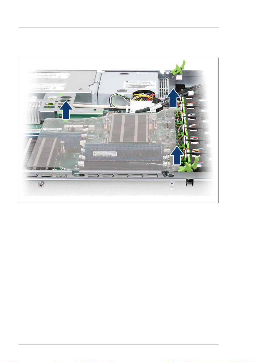
Figure 33: iBBU - Routing the cable
Ê Route the iBBU cable as shown.
I The iBBU cable must pass beneath the power cable that crosses the
iBBU cable.
RX200 S5 Options Guide 55
Page 56

Installing an iBBU Expansion cards and iBBU
1
2
2
Figure 34: Connecting the cable to the modular RAID 5 controller
Ê Connect the free end of the iBBU connection cable to the corresponding
connector on the RAID 5 controller (1).
I The connector is protected against polarity reversal, in other words,
the plug can only be connected one way round.
Ê Connect the SAS cable(s) to the corresponding connectors on the RAID 5
controller (2).
Ê Close the server, connect all power plugs to the power outlets, and switch on
the server as described in chapter “Completion” on page 61.
56 Options Guide RX200 S5
Page 57

10 USB solid state disk (uSSD)
V CAUTION!
Follow the safety instructions in the chapter “Safety instructions” on
page 13.
The system board has a slot – possibly covered by an installed modular RAID
controller – for a USB solid state disk (uSSD). It can be used as optional
memory for software (e.g. VMware) or as a software dongle.
Ê Open the server as described in chapter “Preparation” on page 19.
Ê Remove riser card holder #3.
Figure 35: Position of the uSSD on the system board
Ê Insert the uSSD in its slot (see circle) and screw it in place.
Ê Install riser card holder #3.
Ê Close the server, connect all power plugs to the power outlets, and switch on
the server as described in chapter “Completion” on page 61.
RX200 S5 Options Guide 57
Page 58

Page 59

11 Trusted Platform Module (TPM)
V CAUTION!
Follow the safety instructions in the chapter “Safety instructions” on
page 13.
The Trusted Platform Module (TPM) is installed on the system board between
riser cards #1 and #2 (see photo below). It is used for safe storage of key information (e.g. drive encryption using Windows BitLocker Drive Encryption).
Ê Open the server as described in chapter “Preparation” on page 19.
1
2
3
Figure 36: Installing the TPM module
Ê Insert the plastic post supplied (3) into the square opening between riser
cards #1 and #2 on the system board. Make sure that the post engages.
Ê Insert the TPM (2) in the corresponding socket on the system board and
secure it using the screw supplied (1).
Ê Close the server, connect all power plugs to the power outlets, and switch on
the server as described in chapter “Completion” on page 61.
RX200 S5 Options Guide 59
Page 60

Page 61

12 Completion
V CAUTION!
Follow the safety instructions in the chapter “Safety instructions” on
page 13.
12.1 Fitting the air cowl
Figure 37: Fitting the air cowl
Ê Refit the air cowl. Please note the information described below.
RX200 S5 Options Guide 61
Page 62

Fitting the air cowl Completion
● The plastic pin of the air cowl must slot into the groove of the system board
(see circle):
Slot #3
DIMM CPU #1
Figure 38: Position of the plastic pin of the air cowl
62 Options Guide RX200 S5
Page 63

Completion Fitting the air cowl
● The air cowl must be hooked into the fan brackets on the left and right as
seen from the front (in this case, the right side):
Fan #3/#4
Figure 39: Position of the fan bracket (right side) of the air cowl
RX200 S5 Options Guide 63
Fan #1/#2
Page 64

Fitting the air cowl Completion
● The air cowl must be hooked into the fan brackets on the left and right as
seen from the front (in this case, the left side):
Fan #11/#12
Figure 40: Position of the fan bracket (left side) of the air cowl
64 Options Guide RX200 S5
Page 65

Completion Closing the server
12.2 Closing the server
Ê Position the housing cover so that it protrudes about 1 cm over the back
edge.
Make sure that each bolt is positioned in the corresponding nut.
Ê Push the housing cover all the way forward until it clicks into place.
Ê Fit the fan cover (see “Removing the fan cover” on page 20).
Ê Insert the server into the rack. (The operating manual for the server
describes how to install it).
V CAUTION!
At least two people are needed to position the server in the rack.
Ê Connect all power plugs to the power outlets and switch on the server.
RX200 S5 Options Guide 65
Page 66

Page 67

13 Cabling
13.1 Cabling overview
No. Part no. Description From To
1 A3C40102683 Front VGA cable Front panel board System board
2 A3C40102687 SATA cable ODD Optical Disk Drive
(ODD)
3 A3C40102656 SAS HDD cable Onboard SATA
connection or RAID
controller in slot 3
4 A3C40102678 Front panel cable The control panel System board
5 T26139-
Y3987-V2
Table 1: Cabling overview
iBBU cable iBBU RAID controller
1. SATA
connection
(system board)
2. HDD
backplane
HDD backplane
(CN1 or CN2)
RX200 S5 Options Guide 67
Page 68

Cable diagrams Cabling
13.2 Cable diagrams
13.2.1 Cabling for up to 4 HDD modules
VGA
panel
CN3
Front-
Power
distribution
board
DVD drive
P2
P1
P3
CN2
Fan
Front Panel
PWR
PWR CTRL
1/2
CN1
plane
Back-
6x HDD
Fan
3/4
Fan
5/6
Fan
7/8
SATA
ODD
CPU 2
SATA 1
DIMM 2D
Fan
9/10
DIMM 1D
DIMM 2E
DIMM 1E
Fan
DIMM 2F
DIMM 1F
11/12
Data
Slot 3
PSU 1
PSU 2
uSSD
DIMM 1C
DIMM 2C
DIMM 1B
DIMM 2B
DIMM 1A
DIMM 2A
CPU 1
SAS
SATAPower
Front VGA
iRMC
Slot 2
TPM
Slot 1
D2786
System Board
Key:
Figure 41: Cable diagram for 4 HDD modules with onboard SATA controller
68 Options Guide RX200 S5
Page 69

Cabling Cable diagrams
13.2.2 Cabling for up to 6 HDD modules
VGA
Front
CN3
panel
iBBU
Power
distribution
board
DVD drive
P2
P1
P3
CN2
Fan
Front Panel
PWR
PWR CTRL
1/2
CN1
SATA
Ch. A
ODD
Fan
Ch. B
plane
Back-
6x HDD
3/4
Fan
5/6
Fan
CPU 2
7/8
Fan
DIMM 2D
9/10
DIMM 1D
DIMM 2E
DIMM 1E
DIMM 2F
Fan
11/12
DIMM 1F
Data
Slot 3
iBBU connector
JP5
RAID controller
DIMM 1C
DIMM 2C
DIMM 1B
DIMM 2B
DIMM 1A
DIMM 2A
SAS
CPU 1
PSU 1
PSU 2
SATA
Front VGA
iRMC
Slot 2
TPM
Slot 1
D2786
Power
System Board
Key:
Figure 42: Cable diagram for 6 HDD modules with optional RAID controller
RX200 S5 Options Guide 69
Page 70

Cable diagrams Cabling
13.2.3 Cabling for up to 8 HDD modules
VGA
Front
CN3
panel
iBBU
Power
distribution
PSU 1
board
P2
P1
P3
PSU 2
CN2
Fan
Front Panel
PWR
PWR CTRL
iBBU connector
CN1
Fan
3/4
1/2
SATA
ODD
Ch. A
Ch. B
Slot 3
JP5
RAID controller
Back-
Fan
5/6
DIMM 1C
DIMM 2C
plane
8x HDD
CPU 2
DIMM 1B
DIMM 2B
Fan
7/8
DIMM 1A
DIMM 2A
Fan
9/10
DIMM 2D
DIMM 1D
DIMM 2E
DIMM 1E
CPU 1
Fan
DIMM 2F
DIMM 1F
11/12
Data
SAS
SATA
Front VGA
iRMC
Slot 2
TPM
Slot 1
D2786
Power
System Board
Key:
Figure 43: Cable diagram for 8 HDD modules with optional RAID controller
70 Options Guide RX200 S5
Page 71

Index
5.25 inch DVD bay 7
A
Accessible drives 7
air cowl
fitting 61
removing 22
C
Chipkill 31
components
hardware 5
software 5
D
data manipulation 5
drive cage (8x HDD) 45
DVD drive 38
E
ESD (devices sensitive to electrostatic
discharge) 18
expansion cards 7, 48, 51
H
HDD backplane (6x HDD) 44
HDD backplane (8x HDD) 44
heat sink
installing 25
removing 26
I
iBBU
installing 52
option 7
information, additional 6
intelligent Battery Backup Unit 7
interface
PCIe 7
SATA 7
L
laser information 17
light emitting diode (LED) 17
lithium battery 16
M
main memory
expansion options 7
types 31
meaning of the symbols 9
memory configuration 31
modular RAID controller 51
N
notational conventions 9
P
PCI Express 7
PCIe 7
processor 7, 23
overheating 25
R
RDIMM memory modules 31
riser card 7
S
SATA 7
SDDC function 31
security function 5
T
target group 5
thermal paste
applying 28
removing 26
Trusted Platform Module 8, 59
U
UDIMM memory modules 31
USB solid state disk 57
uSSD 57
RX200 S5 Options Guide 71
Page 72

 Loading...