

Fujitsu NEORE B, NEORE 11, NEORE 14, NEORE 16, NEORE 11 HP User Manual Installation Instruction
...Page 1

User manual
Installation instruction
Heat Pump Neoré
08/2016 - All rights and changes reserved
F
Page 2

1
Basic controls:
For basic controls of the heat pump use graphical touch panel.
Main menu (press button „MENU”)
Elements on display, which are possible to change values, switch ON/OFF or refer to next screen have got orange underlay. After
pressing element is either displayed refered screen or is displayed panel for variable adjustment. Appearence of panel depends
on type of variable.
QUICK SETUP
Descriptions of the controls
Winter operation with DHW
On the main screen set icon and to ON (orange colored rectangle in upper right
corner) . In settings set the required DHW temperature and delays of the DHW electric heating.
For 200l water tank set 40min, 300l - 60min, 400l - 90min. Equithermal curve in section pre-set in the
case of radiators T - at -20°C to 50°C, T - at -8°C to 45°C, T - at +5°C to 40°C, T - at +15°C to 35°C,
and in the case of floor heating T - at -20°C to 40°C, T - at -8°C to 35°C, T - at +5°C to 30°C, T - at +15°C to 25°C.
Then adapt your required temperature by automatic correction of equithermal curve.
Winter operation without DHW
On the main screen set icon to ON and icon to OFF . Equithermal curve pre-set as in
the case of „Winter operation without DHW”.
In heated rooms are cold or too warm
For example, if the room temperature is 2 degrees higher than required, enter the automatic correction eq. curve
in object section to -3°C. When the difference in room temperature eg about 1°C lower than required, enter the
correction + 2°C and so on. The maximum correction is +/- 3°C for one insertion. Remember that change takes
effect after a certain time. For floor heating be aware of delays thermal exchanges in the rooms due to changes in
water temperature 3-6 hrs.
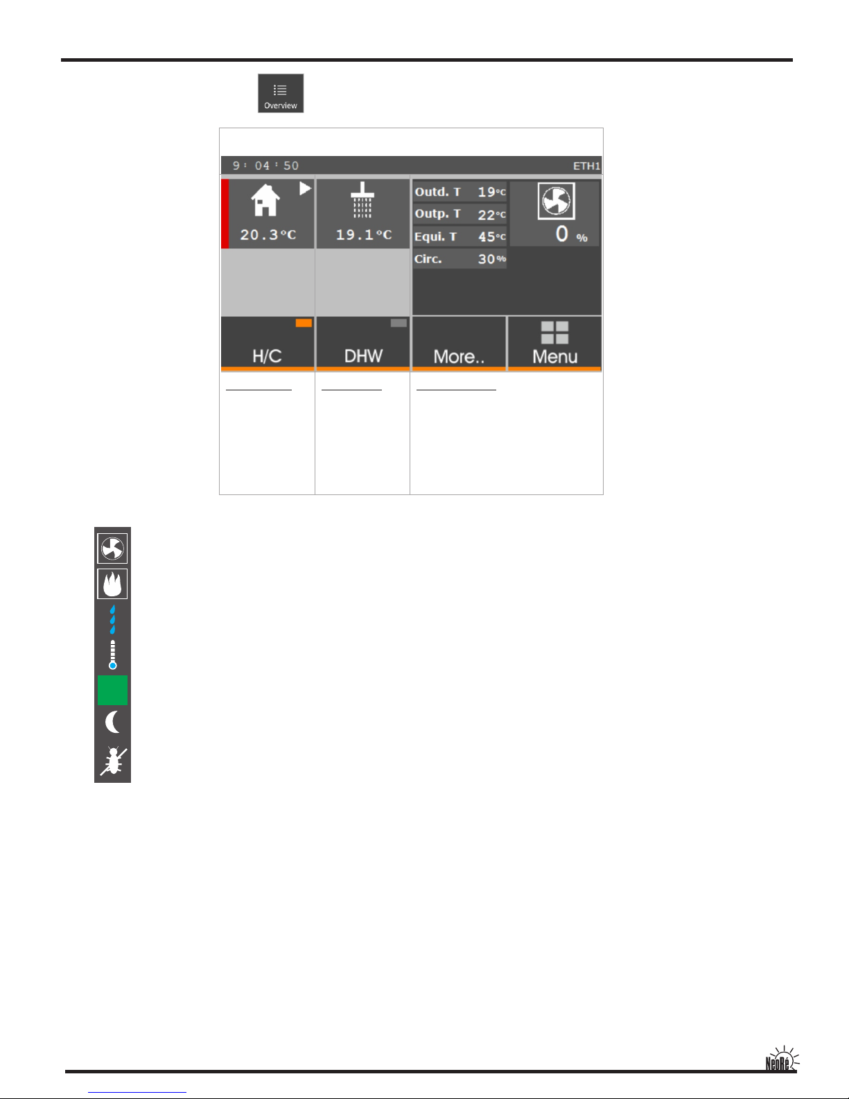
Nastavení
Object section
Displays mode of
heating / cooling, object temp.,
circulator state, object state,
main switch operation
heating / cooling
DHW section
Displays temp. of DHW, DHW
circulator state,
heating state,
main switch DHW heating
Overview section
Displays important
temperatures and paremeters,
operation states, outdoor unit
power, icon of economic
operation, access to main
menu and expanded overview,
whitch contains error history,
measure of supplied power
and more ...
The upper bar displays time, successfully connected Neoré Route (cloud)
service and Ethernet connection.
Graphs of important values
Outdoor unit temperature, object temperature, output water temperature,
DHW temperature, required output power.
Expanded parameter settings of heat pump. This section allows to set maximal
power of outdoor unit, cooling parameters, Ethernet network settings
and more...
This section allows to set parameters of pool heating ande using of secondary
source
DHW heating parameter settings. This section allows set temperature of DHW,
heating and circulation time schedule, follow energy tariff for DHW heating,
bivalent source state and more...
Heating / cooling parameters settings. This section allows to set equithermic
curve, attenuation, follow energy tariff for heating / cooling, required
temperature of object, bivalent source state and more...
Main screen - summmary. Used for switch on / off Heat pump, DHW heating.
Displays the overview of most important values and allows entry to states and
errors screen (button More... → State, errors) and entry to screen of supplied
power measure (button More... → Calorimeter)
Page 3

2
Contents
QUICK SETUP page 1
IMPORTANT NOTICE page 3
1. COMPLETENESS OF THE PRODUCT page 3
2. APPLICATION page 3
3. PRODUCT DESCRIPTION page 3
4. SAFETY PRECAUTIONS page 4
5. MAIN TECHNICAL INFORMATION page 5
6. PRINCIPLE OF OPERATION page 6
7. INSTALATION page 6
8. CONNECTING OF THE REFRIGERANT CIRCUIT page 7
9. FIRST START OF THE HEAT PUMP page 8
10. SETTINGS AND SERVICE OF REGULATOR NEORE UNITY COLOR page 9
11. SERVICE EXTENSION POSSIBILITIES page 15
12. MAINTENANCE page 17
13. INSTALATION page 18
14. PROTECTIVE FUNCTION page 34
15. SERVICE INFORMATION page 36
Page 4

3
Dear consumer,
thank you for purchasing the heat pump Neore. We hope you will be satisfied with the device which shall bring
heat comfort to your house.The pump is a quite complicated device therefore pay high attention to this manual,
please. The manual shall make you familiar with using, placement, construction and further information.
IMPORTANT NOTICE
The heat pump Neore in intended for reduced electricity rates for heat pumps (czech d56) or for convector
heating rate (czech d46).A permission of an appropriate distributor has to be obtained before connecting to the
energy grid.Only authorized company is allowed to carry out installation, connecting, and service. The warranty
card is not valid without authorization.
1.COMPLETENESS
The Neoré heat pump is a split type.
Indoor unit: IO 16 -15 Neoré
Outdoor unit: AOYG....., WOYK.....
Outdoor temperature sensor
DHW temperature sensor
User manual
Warraty card
2.APPLICATION
Heat pumps Neore are intended for heating of houses or small industrial buildings. The product shall be
connected to low-temperature heating system, such as floor heating, wall or ceiling heating. Connecting of wall
heating convectors is possible but maximum temperature of heating water is limited to 50 °C. (60 °C at type HP)
However, efficiency is worse at this temperature (COP decreases). Heat pump can be also used for cooling.
At cooling mode is output water temperature limited to condensing temperature. Heat pump is not suitable for
cooling with water temperature under condensing temperature e.g. fancoil. Low temperature water causes
condensation on inner equipment of indoor unit and thereby the damage. Suitable cooling system cooling ceiling,
where condensation does not occur.
3. PRODUCT DESCRIPTION
Basic construction elements:
- Outdoor unit
It is made from a steel tin with anti-rust treatment which is reached by a powder varnish. Its heart is made by
inverted double level compressor which is a novelty in the field of heat pumps guaranteeing reliability and
longevity. The unit also contains an exchanger with anti-rust treatment and 30 years lifetime, fans with variable
revolutions, electronic expansion valve, controlling and measuring elements.
- Indoor unit
Its main part is a board heat exchanger refrigerant / water. Another substantial part is TECO regulator with
sophisticated software which controls operation of the pump and also controls temperature in the building. The
regulator provides cascade regulation of the heat pump with bivalent supply. There is also a possibility to connect
to the PC via web interface for comfortable and effective control of the heat pump. The unit also contains
protecting, measuring and regulation elements.
i
i
Page 5

4
4. SAFETY
The heat pump is an electrical appliance operating with voltage of 400V! It can be installed and maintained only
by an authorized electrician. In case of fire do not extinguish with water or a foam extinguisher. Use only powder
or carbon-dioxide extinguisher!
In case of refrigerant leakage turn off all circuit breakers placed inside of indoor unit. The refrigerant R410A is
inflammable, non-explosive, non-toxic. Never try to stop the leakage on your own, as temperature very low (up to
-50 °C). In case of a leakage indoor provide fresh air. If you breathe in its fumes or fire exhausts, take the injured
person to the fresh air and call emergency. If the refrigerant is spilled on your skin, dry the place and keep it warm
(e.g. by a duvet). If the refrigerant spills to your eyes, rinse with plenty of water and call emergency.
In case of fire disconnect from the power grid and extinguish by carbon-dioxide extinguisher.
In case of leakage of the heating water, switch off all circuit breakers placed inside of the indoor unit and contact
the maintenance company written on the indoor unit label.
When manipulating with cooling pipes (maintenance) use skin and eyes protection aids (gloves, glasses).
Do not insert your hands or other subjects to the fan of outer unit, there is a threat of a serious injury!
Do not impose air vaporing of the outdoor unit for a long time, there is a threat of hypothermia!
Please follow the conditions set by standards:
EN 378-4:2008, art. 6.5
All parts of the cooling device, e.g. refrigerant, oil, filter, dehydrator, insulation material have to be recuperated,
recycled, and/or disposed in an ecological way in connection with maintenance, repairing, or discarding.
EN 378-4:2008 art. 6.2
Used refrigerant which is not intended to be re-used has to be treated like material intended for safe disposal. It
must be prevented from emissions to the environment.
EN 378-4:2008 Attachments A
Used recuperated oil from the cooling device which cannot be regenerated has to be stored in a suitable separate
container and has to be treated like material intended for safe disposal.
EN 378-4:2008 art. 6.5
All components of the cooling device which contain the refrigerant and the oil have to be disposed in a proper
way.
EN 378-4:2008 art. 6.6
All activities of recuperation and refrigerant re-using and its source have to be recorded in the cooling device diary
(see EN 378-2).
STORAGE AND TRANSPORTATION CONDITIONS
Outdoor unit AOYG....., WOYK.....
Dust-free, non-aggressive enviroment
Temperature -10 až +45 °C
Humidity max 90%
Outdoor unit has to be stored and transported vertically in an originnal package, avoid damage of fragile
parts
Indoor unit Neoré IO16- 15
Dust-free, non-aggressive enviroment
Temperature+5 až +45 °C
Humidity max 70%
Page 6

5
Page 7

6
6. PRINCIPLE OF OPERATION
A heat pump is a device gaining low-temperature energy from a selected source and transforming it to a higher
temperature level. A heat pump air-water system utilizes heat of surrounding air. Its core is a high-performance
compressor which presses down the refrigerant in a hermetic circuit and expands it while using convenient
features of the cooling medium. We use ecological refrigerant R410. On the input side (outdoor unit and the
exchanger) outdoor air is pushed through heat transfer surface of exchanger by a fan. Inside of this exchanger
criculates refrigerant, which passes through expansion valve, and rapidly cooled to a temperature lower than the
ambient air. Refrigerant in exchanger heats up (e.g. from minute 17 to minute 10) and heat recovered is stored in
refrigerant. Then is "compressed" by a compressor and distributed to the condenser (indoor unit). Inside of plate
condenser of indoor unit refrigerant condenses and it transfers the heat into heating medium (heating water).
Thereafter condensed refrigerant goes into expansion valve and the cycle repeats itself.
7. INSTALATION
The device has to be mounted by an authorized company otherwise the device can be damaged or an injury can
be caused.The indoor unit shall be fixed on the wall. Free access to the controlling and protection elements has to
be provided (see the picture below). The outdoor unit shall be fixed by screws to the steel base supplied by the
producer. The steel base is required for a proper defrost of the exchanger. The base shall be fixed to ideally to a
concrete ground whose dimensions avoid falling the unit over during a gale.
Free circulation of air and maintenance access shall be provided (see the picture below). Be aware that outdoor
unit noise might disturb in the surrounding area and avoid it following proper standards.
65 cm
50 cm
65 cm
min 30 cm
500 mm
100 mm
Page 8

7
BASE FOR OUTDOOR UNIT
The outdoor unit is recommended to be placed on a concrete base. The gap between breeze blocks shall be filled
with pebbles. It allows defrosted liquid to leak deep enough and avoids frozen lumps. If you have impermeable
ground, you can improve the condition by using a drainage pipe and spreading the liquid to a larger area.
8. CONNECTING OF REFRIGERATION CIRCUIT
Only authorized service can connect he refrigeration circuit (see Instalation).
WARNING!
Do not try to connect the circuit on your own! There is a threat of a serious injury. The refrigerant is under pressure
of 4,5MPa and temperature is up to -50 °C.
min 300 mm
min 600 mm
Terén
Steel base
Terain
min 300 mm
min 450 mm
min 450 mm
180 mm
Concrete blocks
Drainage tube
The pebbles
650 mm
Page 9

8
BIVALENT SOURCE
Heat pumps Neore contain integrated electric boiler of capacity 6kW. The boiler compensates power loss of the
heat pump at extreme conditions. When external bivalent boiler is used, it is necessary to equip it with all safety
elements (temperature protection, pressure valve, el. protection). The added bivalent source is controlled by the
heat pump only passively. It means it must contain its own regulation so that heating water temperature is not
exceeded, e.g. for the floor heating.
9. FIRST START OF THE HEAT PUMP
It is necessary to put water into the circuit before you launch the heat pump. Reach basic pressure 1 - 1.5 bar.
According to water column add 0.1 bar for every meter height of the heating system. Next, it is necessary to bleed
the circuit thoroughly. The bleeding is done by the bleeding screw of the circuit pump or, alternatively, on the upper
threaded piece of the board exchanger. When the circuit pump is switched on, the board exchanger shall be bled
thoroughly. After that its noise is decreased. The circuit pump shall run for 10 minutes at least before the
compressor is switched on. After watering and bleeding electric equipment shall be used.
Description of protection elements of the heat pump
BIVALENT SOURCE - protection of bivalent source
OUTDOOR UNIT - protection of outdoor unit
TECHNOLOGIE - protection of technology (regulator, 3-way valve, circ. pump.....)
DHW EL. HEATING - protection of DHW electric heating
EMERGENCY STOP
when refrigerant leak
BIVALENT SOURCE
OUTDOOR UNIT
DHW EL. HEATING
TECHNOLOGY
The heat pump breakers; one phase type
Page 10

9
Graphs of important values
Outdoor unit temperature, object temperature, output water temperature,
DHW temperature, required output power.
Expanded parameter settings of heat pump. This section allows to set maximal
power of outdoor unit, cooling parameters, Ethernet network settings
and more...
This section allows to set parameters of pool heating ande using of secondary
source
DHW heating parameter settings. This section allows set temperature of DHW,
heating and circulation time schedule, follow energy tariff for DHW heating,
bivalent source state and more...
Heating / cooling parameters settings. This section allows to set equithermic
curve, attenuation, follow energy tariff for heating / cooling, required
temperature of object, bivalent source state and more...
Main screen - summmary. Used for switch on / off Heat pump, DHW heating.
Displays the overview of most important values and allows entry to states and
errors screen (button More... → State, errors) and entry to screen of supplied
power measure (button More... → Calorimeter)
10. Settings and service of regulator Neoré Unity Color
Basic controls:
For basic controls of the heat pump use graphical touch panel.
Main menu (press button „MENU”)
Elements on display, which are possible to change values, switch ON/OFF or refer to next screen have got orange underlay. After
pressing element is either displayed refered screen or is displayed panel for variable adjustment. Appearence of panel depends
on type of variable.In section of object, DHW, graphs, settings and more are variables arrayed to vertical lists divided to parties.
Description of the control panel NeoRé
Nastavení
Page 11
10
Description of sections
- Overview - main screen
Object section
Displays mode of
heating / cooling,
object temp.,
circulator state,
object state,
main switch
operation
heating / cooling
DHW section
Displays temp. of
DHW, DHW
circulator state,
heating state,
main switch DHW
heating
Overview section
Displays important temperatures and
paremeters, operation states, outdoor
unit power, icon of economic operation,
access to main menu and expanded
overview, whitch contains error history,
measure of supplied power
and more ...
The upper bar displays time, successfully connected Neoré route (cloud) service
and Ethernet connection.
Heatpump operation. For heating / cooling / DHW heating is used heat pump.
Secondary source operation. For heating is used secondary source. For DHW heating is used heat pump.
Defrost. Outdoor unit defrosts. DHW heating is interrupted.
Too low temperature of outdoor air. For heating is fully used bivalent source (internal electric heater).
Economic operation. Displayed when output water temp. is lower than 45°C and the power is lower than 50%.
DHW heating is blocked by time schedule
Antilegionella. DHW tank is heated by electric heater because of legionella desinfection
e
Status icons
Meaning of text shortcuts
Attenuation - attenuation is active, parameter settings in section Object
High tariff! - operation is blocked by electricity supplier
DHW heat. - DHW heating by heat pump
DHW el. heat. - DHW heating by electric heater
Drying - floor drying program is active
Pool heat. - pool is heated by heat pump
Bival 1st. 2st. - bivalent source operation (1st. - first stage (2kW), 2st. - second stage (4kW))
Outd. T - outdoor air temperature
Outp. T - output water temperature
Equi. T - temperature computed by equithermal curve for primary circuit
Circ. - circulator power
Obj. T - object temperature
IQ corr. - IQ correction - correction applied to equithermal curve by object temperature
Page 12

11
Section - More...
2. circ - secondary circuit mixing valve opening
2. equi. - temperature computed by equithermal curve for secondary circuit
2. outp. - output water temperature for secondary circuit
Outdoor temp. - outdoor temperature
Comp. - compressor speed
Vent. - ventilator speed
Hours in use - number of operation hours of heat pump
Section - Calorimeter
Water flow - water flow through indoor unit
Actual power - actual power supplied by heat pump
Supplied power - power supplied since last calorimeter reset
Circulator power - actual circulator power
Water pressure - water pressure inside of system
Out./In. - water temperature output / input
Section - Status Errors
Code of states and errors - four-digit code (read from left)
1. digit: 1 - Freeze protection (output water temperature dropped below safe limits)
2 - Insufficient water flow (water flow dropped below safe limits)
3 - Outdoor unit disorder
4 - Low water pressure (water pressure dropped below 0,9 Bar)
5 - Faulty temperature sensor MX (communication unit)
2. digit: 1,2 - Faulty output water temperature sensor
3,4 - Faulty input water temperature sensor
3. digit: 1,2 - Faulty pool temperature sensor
3,4 - Faulty secondary circuit temperature sensor
4. digit: Faulty outdoor temperature sensor 1,2 -
3,4 - Faulty object temperature sensor
5,6 - Faulty DHW temperature sensor
7,8 - Faulty accumulatice tank temperature sensor
First two digits from left indicate critical error, in which is heat pump operation stopped or limited.
Autoreset - Function of error autoreset. If the error disappears, heat pump is again put into operation. This could
happen maximum 5 times, autoreset function is deactivated thereafter.
Error history- Error history records last 10 errors.
Description of sections
- Overview - main screen
Page 13

12
Description of sections
- Object
pg. 1 Follow energy tariff - follow electricity supplier energy tariff for heating / cooling of object
Mode - heating / cooling - heating / cooling mode switch
Use an object sensor - switch specifies, if an object temperature sensor is used for equithermal curve correction
(IQ equitherm)(for this option must be indoor temperature sensor connected)
Required T of object - target object temperature for IQ equitherm and target object temperature for cooling
Required T of cooling water - required cooling water temperature; heat pump is designed for cooling above
condensing temperature (cooling ceilings, etc.)
pg. 2 Output water correction - correcction, which is applied to actual computed value of equithermal curve; it is used for
short-term output water temperature correction (e.g. to cover unexpected energy loss or profit)
IQ correction gain - If the indoor temperature sensor is used for object temperature regulation, the equithermal curve
is corrected by IQ correction function. This function must be always set correctly.
IQ correction - displays actual computed value of IQ correction
IQ correction = ((Object T - Required T of object) * IQ correction gain) + temp. computed by equithermal curve
Prim. equitherm. T - actual temperature computed by equithermal curve for primary circuit and access to equithermal
curve settings
Equithermal curve - name explanation
Equithermal regulation is the kind of temperature regulation, where output water temperature from heat source
(heat pump) is set by outdoor temperature. The lower outdoor temperature means higher output water
temperature. It deliver significant savings in conjuction with a heat pump, which quickly lose effeciency as the
heating water temperature rises. If the equitermal regulation is properly set up guarantees temperature comfort
in the rooms in the form of temperature stability without fluctations.
In Neore heat pump are used two tools for comfort settings of equithermal curve:
1. Neo Equitherm - Automatic correction write down desired adjustment of heating water temperature without you
have to think about which value and how much to change.
2. IQ Equitherm - Automatic fine tuning of equithermal curve by difference of required and actual temperature of living
space. This tool is suitable for heating systems with good dynamics (radiators, fancoils, ceiling heating, etc.) At
heating systems with bad dynamics (floor heating, wall heating) is recommended to use regulation by standard
equithermal curve only .
The recommended procedure for setting equithermal curve:
1. Set default values of heating water of equitremal curve approximately as follows:
2. For example, if the room temperature is 2 degrees higher than required, enter the automatic correction eq. curve in
object section to -3°C. When the difference in room temperature eg about 1°C lower than required, enter the
correction + 2°C and so on. The maximum correction is +/- 3°C for one insertion. Controller itself modifies
equithermal curve by actual outdoor temperature. If another correction is needed, you enter it the same way. In
this manner you set all the equithermal curve and another change will not be necessary. Remember that change
takes effect after a certain time.
3. If the equithermal curve is set correctly, you can use IQ equitherm, which monitors set and actual temperature of
room and in case of difference automatically changes heating water temperature. It is suitable to cover
unexpected temperature gain (sun, fireplace, more people in room, etc.) or losses (wind, higher humidity of
outdoor air, etc.).
Correct settings of equithermal curve of heat pump is very important and benefit for really noticeable cost savings for
heating.
Floor heating:
outdoor temp. (fixed value) heating water temp.
-20°C 38°C
-7°C 33°C
6°C 28°C
19°C 22°C
Radiators:
outdoor temp. (fixed value) heating water temp.
-20°C 55°C
-7°C 45°C
6°C 35°C
19°C 23°C
Page 14

13
Description of sections
- Object
pg. 2 Sec. equitherm. T - actual temperature computed by equithermal curve for secondary circuit and access to
quithermal curve settings (same principle as the primary circuit)
Attenuation time schedule - attenuation settings for output water temperature and potential outdoor unit power limit
after a certain time. Two time zones for every day. Inside of the time zone heat pump works normally and
outside of time zone is in attenuation. When attenuation is active (outside time zone), output water temperature
is decreased by the value set on last page of attenuation time schedule. If the attenuation si set to 0°C, time
schedele have not got any influence to output water temperature except outdoor unit power (if is enabled).
Outdoor unit power limit you can set in Settings -> Outdoor unit max power and switch Only in the attenuation
must be set to ON.
pg. 1 Required DHW temperature - required DHW temperature (recommended 44-48 °C)
Required DHW hysteresis TUV - required hysteresis (define temperature difference when starts DHW heating)
DHW el. heating delay - define time to DHW heating by heat pump; after this time is is DHW heated by electric
heater and heat pump is used for object heating.
Desinfection - switch ON / OFF DHW tank desinfection; on a fixed time (saturday 1:00 - 10:00) tank is heated by
electric heater to selected temperature
Required DHW desin. temp. - required tank temperature for legionella desinfection (min 60°C)
Follow en. tariff for DHW heating - DHW heating is blocked by electricity supplier high energy tariff
pg. 2 DHW circulation - DHW circulator operation control (if is installed)
Circulation time schedule - DHW circulator time schedule (two time zones per day)
DHW heating time schedule - DHW heating time schedule (one time zone per day)
Graphs of important values
pg. 1 Output water
pg. 2 Required power
pg. 3 Outdoor temperature
pg. 4 DHW temperature
pg. 5 Object temperature
- DHW
- Graphs
Page 15

14
Description of sections
- Settings
pg. 1 Current limit per 1 phase - at one phase units may experience overloading when runs together with bivalent source;
this function cause that first stage of bivalent source will not be used for bivalent operation
Secondary circuit - define if the seconadry circuit control is used (external mixing valves)
Outdoor unit max power - enable to set outdoor unit maximal power (mainly used for noise reduction)
Only in the attenuation - outpdoor unit power limit is active only when attenuation is active
Bivalent operation - if the outdoor temperature is lower than this limit, for heating is used bivalent source only
Cooling water - output water temperature in cooling mode (keep temperature above dew point (ca. 18°C and more)
is necessary
pg. 2 Date / time - date and time settings
Webserver - name - webserver login name
Webserver - password - webserver login password
Saved data - heat pump operation saved data (access is possible only from PC)
Network settings - ethernet network connection settings
pg. 3 Service access - access only for service engeneer
pg. 1 Secondary source - enable use of secondary source (solid fuel boiler, solar panel, etc.)
Secondary source tank temp. - actual temperature in secondary source accumulation tank
Secondary source hysteresis - if the accumulation tank temperature is higher than temperature computed by
equithermal curve + hysteresis, the heat pump is stopped and secondary circuit starts. Thereby is heat
transferred from accumulation tank to object.
Pool - pool heating switch ON / OFF
Pool temperature - actual pool temperature
pg. 2 Required pool temperature - required pool temperature
Required pool hysteresis - pool heating hysteresis
Temp. of pool heating water - temperature of output water for pool heating
Pool heating time schedule - time schedule for pool heating (one time zone per day)
- More
Page 16

15
11. SERVICE EXTENSIONS POSSIBILITIES
INTE RNET
INTE RNET
WI-FI
WI-FI
ETHE RNET 100Mbit FD
WEB SERVER SERVICE
To connect to the heat pump web site the controller must be plugged into an Ethernet network and configured
correctly. Then you can access the web interface from the computer Internet browser with support of XML standard.
Enter IP address of heat pump into your browser address bar. The computer must be on the same physical Ethernet
network. If you want to control heat-pump from the Internet network, contact your internet provider. The default IP
address of a heat pump is "192.168.134.176". The username is "eneore" and password is "eneore". This address
and other settings can be changed in the "Settings" in the heat pump controller.
Operation of the heat pump via a Web server control is intuitive and has the same character as the control panel of
the controller.
Page 17

16
Neota Route is new service of NeoRé heat pump, which secure user accessto web server through the Internet
network without need of public IP address and exactly router mapping. The heat pump needs only Internet
connection as well as any computer.
For Neore heat pump connection to Neota Route, you have to contact yours heat pummp supplier, or apply for
openning an account by email at support@neota.eu. Neota Route is a paid service. After paying a one-time fee you
will recieve user name and password, which is needed to insert to heat pump web server settings (Settings ->
Network settings).
IMPORTANT NOTICE
That the Neota Route service is available, is needed to router, which is used for heat pump Internet connection,
have got enabled outgoing TCP port 8080.
NEOTA ROUTE SERVICE
Page 18

17
12. MAINTENANCE
This heat pump because of its construction requires really low maintenance. The basic maintenance will be
provided by service company once a year. During this service will be checked all crucial parts of the heat pump.
Especially the amount of refrigerant in circuit and refrigerant circuit function.
It´s important to check outdoor unit exchanger. You can clean it using garden washer with hot water. This way you
will clean it from raid of insects and any ice.
Don´t use high-pressure cleaners and any mechanical aids like brush etc. The exchanger is very soft
and could be damaged. Before cleaning of exchanger switch off the main circuit breaker in inside unit
The inside unit needs minimal maintenance. Use a damp cloth for cleaning its top cover and follow caution if the
heat pump is running and energized. We recommend to do indoor unit maitenance outside the heating season.
Check an activity of circulator before the heating season. Especially if it is not jammed. Once a year let
checked expansion vessel function, safety valve and heating water filter clogging.
You should better leave all these jobs to service company..
Disconnect heat pump from the mains voltage before you remove its cover. In other case threatening
injuries and eventually death because of electric shock.
circulator
expansion tank
Page 19

18
For authorized person
This air conditioner uses new refrigerant HFC (R410A).
The instalation of the device is the same like instalation of devices with R22, R407, R134 refrigerant etc.
It´s necessary to keep these rules:
1 The pressure is about 1,6x higher than pressure with convectional refrigerants. Therefore is necessary to use
special instruments and measure equipment. It´s necessary to use copper pipeline with homologation for R410A
refrigerant for connection of inside and outside unit. If you work with refrigeration technology, you should
use protective equipment such as glasses, gloves etc.
2 This device with R410A refrigerant uses different service connection from convection refrigerants, which prevents
against connection of unapproved service tool. The connection for R410A refrigerant is 1/2 UNF (standard R410
accessories).
3 Don´t use pipeline which was used with another refrigerant or lubricating oil. The pipeline must be extremely clean
and dry. Storage and transportation of pipeline must be in closed state.
4 Filling and exchange of refrigerant must be in liquid state when the refrigerant is stable and both parts are added in
the correct ratio. The R410A refrigerant consists of two parts.
Special tool for R410A refrigerant
Description
The pressure is 1,6x higher. Using of these manometers for convection refrigerants may lead to their
destruction. These manometers have also different connection.
Service hose must be specially designed for R410A refrigerant.
It´s used convection vacuum pump with adapter for connecting to R410A refrigerant.
Leak detector must be homologated for R410A refrigerant.
Tool´s name
Manometers
Service hose
Vacuum pump
Leak detector
This device contains new HFC refrigerant (R410A)
DANGEROUS
This sign informs about the most important information such a protection against the danger
of electric shock, injury caused by leaking refrigerant etc.
WARNING
This sign informs about important information about safe run of the device.
ATTENTION
This sign informs about information to which you should pay attention.
Copper pipeline
Minimal wall thickness of copper pipeline (R410A)
DANGER DANGEROUS
Models: NeoRé 8, 11, 14, 16 (HP)
Attention
refrigerant
This product contains refrigerant
R410A and polyester oil
This product can be installed
only by producer-approved companies
13. INSTALATION MANUAL
Inside and outside unit have to be disconnect from electrical network before any manipulation with electric device.
After disconnection is necessary to wait at least 5 minutes until capacitors of the electric circuit are discharged.
6,35 mm (1/4 in.)
9,52 mm (3/8 in.)
12,70 mm (1/2 in.)
15,88 mm (5/8 in.)
19,05 mm (3/4 in.)
0,80 mm
1,00 mm
1,00 mm
1,00 mm
1,20 mm
pipeline size
thickness
Page 20

19
WORKING CONDITIONS
The heat pump can be used as heat source for heating or cooling and for heating of water.
Working environment:
environment by ČSN 33 2000-3 for outside unit AA2-AA5; AB7; AD3
environment by ČSN 33 2000-3 for inside unit. AA5; AB5
The heat pump musn´t be placed and installed in environment with the risk of explosion of
combustible gases by ČSN 33 2000-3.
Technical parameters of electric suply:
rated voltage 3x400/230V +/-10% 50Hz
maximal input power according to the output table
electrical class TN-C-S ČSN EN 33 2000-3
protection class ČSN EN 60335-1
protection cover outdoor unit IPX4
indoor unit IP40/20
Refrigerant circuit
refrigerant HF R410A CH F /C HF - 50/50 (filling by type)
2 2 2 5
Maximal pressure 4,2 MPa (gas), 1,05MPa (liquid)
max. working overpressure 2,5bar
min. working overpressure 0,8bar
max. working temperature 60°C
Refrigerant exchanger freeze
The basic frost protection of exchanger refrigerant/water is to ensure minimal flow througth exchanger .
This crash of refrigerant exchanger threatens only during defrosts. It´s necessary to ensure there is not any
regulatory element in the heating circuit which should close or significantly constrict the circuit of the heating
water. During initial startup of the heat pump or after it´s shutdown the heating water must have temperature
of at least 10°C. Minimal water flow of heating water is 400 l/hr.
Page 21

20
WARNING
1 Install only according to this manual.
2 Connect inside and outside unit (refrigerant, electric) only by using the material mentioned in the manual.
3 Installation of refrigerant and electrical circuit can be performed only by authorized persons.
4 Don´t use flexible cords and pipelines for the units connection.
5 Don´t run the device which is not completely installed.
6 Don´t use refrigerant of unknow quality and cleanliness. Keep the safety rules.
7 Don´t add refrigerant to boost of output power.
8 Always use the vacuum pump before you fill refrigerant.
9 Respect work safety and use protective equipment during installation.
65 cm
50 cm
65 cm
min 30 cm
500 mm
100 mm
PLACEMENT AND INSTALLATION
The heat pumo must install professional company authorised by manufacturer. Do not try it yourself.
It may lead to device destruction or injury to persons.
The indoor unit will hang on the wall fixed to mounting plate. It´s placement must be done considering possible
access to regulatory and protective devices and for service. See picture below. The outdoor unit will be screwed to
the pedestal. The pedestal is necessary for the effective defrosting. This pedestal must be securely attached to
the concrete pad. The pad should have the size which excludes the overturn of the unit during windy weather.
The placement should not inhibit the air flow and also alllows service and repair access. The placement in dense
development must be chosen so that fan noise meets noise standards. In some cases is suitable to make noise
test.
environment by ČSN 33 2000-3 for outdoor unit AA2-AA5; AB7; AD3
environment by ČSN 33 2000-3 for indoor unit AA5; AB5
Page 22

21
Crimping
The crimping must be done with quality refrigeration tools. The pipeline must be cutted by cutting wheel. You will limit the creation
of the sawdust. Then you have to get rid of the edge of the pipeline which cutting wheel created. Then the crimping should be done according
to the parameters shown in this table.
Connection of refrigerant circuit
Pipeline have to be isonlated enough
MAX.
75 m
50 m
Lenght
MIN.
5 m
30 m
Max. height
diffefence
Model
Liquid
Gas
9,52 mm (3/8 in.) 15.88 mm (5/8 in.)
Neoré 11, 14, 16
Pipeline size
6,35 mm (1/4 in.)
9,52 mm (3/8 in.)
12,70 mm (1/2 in.)
15,88 mm (5/8 in.)
19,05 mm (3/4 in.)
0 to 0,5
Outside size of pipeline
Overlap A
(mm)
Crimp. tool for R410A
Outside size of pipeline
Size of Crimp B
(mm)
6,35 mm (1/4 in.)
9,52 mm (3/8 in.)
12,70 mm (1/2 in.)
15,88 mm (5/8 in.)
19,05 mm (3/4 in.)
9,1
13,2
16,6
19,7
24,0
Neoré 8
Attention
Don´t exceed maximum lenght of connecting pipeline. In other case preformance parameters can´t be fulfilled and the device
could be destroyed.
ATTENTION
ATTENTION
Use only the insulation suitable for refrigerant circuits. The temperature of pipe surface can reach temperature of 120°C!
For outside environment use insulation at least 20 mm thick. For the inside environment suffices 10-15 mm.
Mentioned parameters apply for insulation with thermal resistance 0,045 W/(m.K) or better (at 20°C).
At crimpring don´t use mineral oils on any parts. In other case you can reduce device life. In case of soldering fill the
pipeline with nitrogen gas for avoidance scales (minimum hardness 50% Ag). The gas must not be under pressure.
B
Calibr
A
Pipeline
Page 23

22
ATTENTION
Hold torque wrench at the right angles to the pipe.
This is the only way to the correct function.
rozměr potrubí utahovací moment
6,35 mm (1/4 in.) dia.
9,52 mm (3/8 in.) dia.
12,70 mm (1/2 in.) dia.
15,88 mm (5/8 in.) dia.
19,05 mm (3/4 in.) dia.
14 to 18 N·m (140 to 180 kgf·cm)
33 to 42 N·m (330 to 420 kgf·cm)
50 to 62 N·m (500 to 620 kgf·cm)
63 to 77 N·m (630 to 770 kgf·cm)
100 to 110 N·m (1000 to 1100 kgf·cm)
20 to 25 N·m (200 to 250 kgf·cm)
20 to 25 N·m (200 to 250 kgf·cm)
25 to 30 N·m (250 to 300 kgf·cm)
30 to 35 N·m (300 to 350 kgf·cm)
35 to 40 N·m (350 to 400 kgf·cm)
10 to 12 N·m (100 to 120 kgf·cm)
Torque of stopper plug
Lo
Hi
manometer
service hosepipe
vacuum pump
pipeline
stopper plug
hex key
3-way valvel
service port
stopper plug
service hosepipe
R410A
Outdoor unit
use 4 mm
hex key
3-way
valve
6,35 mm (1/4 in.)
9,52 mm (3/8 in.)
12,70 mm (1/2 in.)
15,88 mm (5/8 in.)
19,05 mm (3/4 in.)
Service port
ATTENTION
t
3-way valve
(liquid)
3-way valve
(gas)
Pipeline to a cone of ertly!3-way valve center prop
Apply alkylbenzene oil (HAB)
for refrigerant leak prevention.
Don´t use mineral oils!
Vacuum
(1) Unscrew the plug of 3-way valve service access (gas). Connect it with manometer
which is suitable for vacuum pump and measuring of vacuum.
(2) Run vacuum pump and evacuate for approx. 15-20 minutes. Don´t open 3-way valves!
(3) Do leak test - wean vacuum pump and control manometer after 60 minutes.
(4) If it is necessary add requested amount of the refrigerant.
(5) If you added refrigerant, disconnect service hose (beware refrigerant leaks -
use protective equipment). If you didn´t add any refrigerant, open a 3-way valve
slowly and carefully (liquid) and fill a pipeline by pressure from the unit for
pressure equalization (check a manometer).
Then you can disconnect service hose and screw a plug of service port.
(6) Open both 3-way valve (liquid first). Reinsert plugs to the original post and tighten
it according to the requested moments shown in the table.
(7) Do leak test of refrigerant circuit with a leak detector.
Do not disconnect
vacuum circuit before
you reach at least
refrigerant pressure.
Page 24

23
REFRIGERANT REPLENISHMENT
Every unit is prefilled by R410A refrigerant. It is not necessary to replenish any refrigerant. In a case of refrigerant leak and loss, add
necessary amount according to the external unit label or according to this table.
Neoré 14, 16
Neoré ..HP
Neoré 8, 11
3,35 kg
2,5 kg
1,7 kg
Model
Fill of regrigerant
3
This air conditioner uses new refrigerant HFC (R410A).
The instalation of the device is the same like instalation of devices with R22, R407, R134 refrigerant etc.
It´s necessary to keep these rules:
1 The pressure is about 1,6x higher than pressure with convectional refrigerants. Therefore is necessary to use
special instruments and measure equipment. It´s necessary to use copper pipeline with homologation for R410A
refrigerant for connection of inside and outside unit. If you work with refrigeration technology, you should
use protective equipment such as glasses, gloves etc.
2 This device with R410A refrigerant uses different service connection from convection refrigerants, which prevents
against connection of unapproved service tool. The connection for R410A refrigerant is 1/2 UNF (standard R410
accessories).
3 Don´t use pipeline which was used with another refrigerant or lubricating oil. The pipeline must be extremely clean
and dry. Storage and transportation of pipeline must be in closed state.
4 Filling and exchange of refrigerant must be in liquid state when the refrigerant is stable and both parts are added in
the correct ratio. The R410A refrigerant consists of two parts.
This device contains new HFC refrigerant (R410A)
4
Page 25

24
ELECTRICAL INSTALLATION
The scheme of connecting to the elecric installation see on the picture undet the text.
Connection, repairs and check of the electric installation may do only authorized person. Proffesional involvement
must be confirmed on the warranty certificate.
Electric installation must respond to the applicable electrical standards ČSN, especially ČSN 37 5215. Check of
the electrical circuits will be done after the installation of the heating system and its flooding.
The electric installation scheme see in attachment 1.
terminal
1
2
3
L3
N
PE
outdoor unit
5X4(6) Cu mm
3(5)X4(6) Cu mm
3X1,5 Cu mm
Model
Neoré 8, 11, 14, 16
Connecting the electric circuit
2
Cross-section of power and communication wires (mm )
Model
Cross-sec. of power cable
Cross-sec. of comm. cable
Breaker capacity (A)
MAX. MIN. MAX. MIN.
6 4 2,5 1,5
DANGER DANGEROUS
XL XN XC
PE
N
actuator (servo)
mix. 2nd circuit
(optional)
external
power
input
X1:1
XOU:1
Xobeh
Xbazen
Xbazen
Xbazen
6*
X1:1
X1:3
X1:2
XOU:1
XOU:2
XOU:3
S
L2
L1
Three-phase el. connection
Three-phase el. connection
cables
XNS
XL
XB1.1
Xobeh
XOAKU
XB1.2
XOTUV
XcircT
XOBAZ
XNS
XGND
XTven
XTtopv
XC-3
XTTUV
XN-2
XTobj
X24+
X24-
Xt2okr
XTaku
X2gnd
XTbaz
Xtvrat
X2-10V
XL-1
1
2
3
3x25
indoor unit
Inside and outside unit have to be disconnect from electrical network before any manipulation with electric device.
After disconnection is necessary to wait at least 5 minutes until capacitors of the electric circuit are discharged.
Page 26

25
Indoor unit
actuator (servo)
mix. 2nd
(optional ESBE VRG131, ARA639)
DHW tank
max 2000W
If the heat pump heats DHW,
connection of electric heater
is needed. It is used for tank
desinfection and as a backup
heat source.
Otherwise software will not
work correctly and might
completely exhausted
hot water!
M
=
Y
T
N
Y
indoor unit
5X4(6) Cu mm
5X2,5 Cu
3X4 Cu
3X1,5 Cu
XNS
XL
PE
PE
N
N
6*
X1:L1
X1:L3
X1:L2
XOU1:1
XOU1:3
XOU1:2
1* Outdoor temperature sensor
(must be connected; if is not, output water temperature will be
regulated to the default value of equithermal regulation 20°C)
2* Heating water temperature sensor (internal)
3* DHW temperature sensor
(sensor is placed inside of DHW tank; needed for direct DHW heating)
4* Indoor temperature sensor (reference room)
If you would like to use regulation by object temperature,
you have to activate it (Object -> Use an object sensor).
Then the heat pump corrects equithermal curve by indoor temperature.
Sensor types - all of the system ni1000 - 6180ppm/K
1*
2*
3*
4*
*
outdoor unit
XOTUV
X2-10V
XGND
X24+
- by type
*
XB1.1
Xobeh
XOAKU
XB1.2
XOTUV
XcircT
XOBAZ
XNS
XGND
XTven
XTtopv
XC-3
XTTUV
XN-2
XTobj
X24+
X24-
Xt2okr
XTaku
X2gnd
XTbaz
Xtvrat
X2-10V
XL-1
Terminal description - indoor unit
X1:L1 - 3 (podle typu) Lead 400/230V TN-C-S min 25A
XOU1:1 - 3 (podle typu) Outdoor unit power supply 400V max 16A
XB1.1; XB1.2 External bivalent source control (1. and 2.
stage). 230V max 2A
Xoběh Circulators power 230V max 6A
XOTUV DHW heating - DHW tank electric heater power
supply 230V max 10A
XcircT DHW circulation output 230V max 1A
XOAKU Output for use of secondary source (accu. tank
e.g. solar) 230V max 2A
XOBAZ Output for 3-way valve and pool circulation
control 230V max 2A
XNS Input for rate of cost- N, current 200mA
X24+ Output 24V+ ss
X24- Output 24V - ss
Xgnd Com for sensors Ni1000.
XTven Outdoor temperature sensor
XTobj Indoor temperature sensor
XTtopv Output water temperature sensor (internal)
XTvrat Input water temperature sensor (internal)
XTTUV DHW temperature sensor
XTaku Secondary source accu. tank temperature sensor
XTbaz Pool heating water temperature sensor
Xt2okr Secondary circuit heating water temperature
sensor
XL-1,XN-2,XC-3 Outdoor unit communication
X2gnd GND pin of actuator (servo) 0-10V 2nd circuit
X2-10V Signal pin of actuator (servo) 0-10V 2nd circuit
Page 27

26
HEAT PUMP CONNECTION TO HEATING SYSTEM
Designing
The heating system design quality is very improtant, as well as quality of heating water and used materials.
Insufficient flow of heat transfer medium causes increase in condensing temperature and thereby significant
reduction of COP (Coeficient Of Performance). Badly designed regulation system has the same effect. On the
other hand, too high flow causes erosion corrosion attack. Insufficient size of expansion tank is directly related
with possibility of corosion of heating system.
Installation and commissioning
Seemingly insignificant differences between project and realization may lead to malfunction of heating system.
Quality joints, soldering process, rinsing of heating system and first heating are good prerequisite for customer
satisfaction. Cost savings by installing heating system without people with appropriate qualification is intolerable
risk.
Used materials and devices
This problem is associated to project of heating system. Designer should avoid solutions where are used more
materials e.g. copper pipes, aluminium radiators and steel boiler. Such a system can not be protected against
various types of corrosion. Use of certified materials is always preferred. The same applies to seal, flux, solder
etc.. Total corrosion of heating system is very often caused by use of plastic pipes without oxygen barrier for floor
heating.
Heating water quality
Quality of heating water is decisive for long-term and trouble-free operation of heating system. Properties of used
water as heat transfer medium depends on location and type of water supply. It is important to note that water
with properties of drinking water mostly is not suitable to use as heating water without preparation. For heating
systems are important parameters like hardness, salinity, acidity and the content of dissolved gases.
Hardness of water means amount of Ca2+ and Mg2+ salt which during operation conditions changing solubility
and creates practically insoluble carbonates. Limescale forms mostly on bivalent source and negative effects
performs by the following mechanism. Initially creates thin thermal insulating layer. This layer decreases power
of source and also occur local overheating. From unequal dilation at the spot of overheating, compactness layer
is breached. Chipped limescale pieces get into the water and gradually clog refrigerant exchanger and regulation
valves. Carbon dioxide arises during the build up of limescale and causes occurence of air inside of system and
surface corrosion, if the conditions are good. Moreover it is necessery to fill water missing.That is not mostly
adapted and it brings the system into further adverse effects.
Salinity expresses amount of all dissolved salt in water. In practise it is the cations Na+, K+, Fe2+ and anions
Cl- and SO42-. Ions of Fe2+, Cl- a SO42- does not support corrosion of heating system. Water salinity is directly
proportional to its elecctrica conductivity. High values of water salinity helps to electrolytic corrosion especially
when are used more different types of material in heating system (copper, steel).
Acidity of water (pH) is significant criterion for corrosion behavior of system. Because of minimizing corrosion
efficiency, the value of pH of used water should match used materials. It is important to note that pH suitable
for steel is not suitable for example for aluminium etc..
Amount of dissolved gases in water depends on its temperature and pressure of gases. At heating water it is
mainly about dissolved air contains primarily N2, O2 and CO2. From chemical point of view nitrogen in heating
sstem is harmless. But from operation point of view affects adversely. Decreases thermal capacity of water,
increases the compression work and causes cavitation noise. Oxygen and carbon dioxide active corrosion and it
is needed to remove from the water. The most of dissolved gases could be removed from heating system by
bleeding. But it is not possible to remove gases from heating water completely.
If the system is bleeded correctly, a rest of gases in water have do not have got underlying influence to long-term
lifetime and reliability of heating system. Residual oxygen is consumed during corrosion and than corrosion is
stopped. The biggest danger is repeated intrusion of oxygen into system. In practise is this fact the most often
cause of corrosion of system. The reason could be bad tightness of system, wrong parametres of expansion tank,
quality of sealing elements and used plastic parts. Keep in mind that etc. floor heating made from plastic with an
oxygen barrier conforming to norm is not 100% resistent against the diffusion of oxygen. In this case occurs the
oxygen intusion repeatedly corrosion never stops spontaneously. Use of oxygen absorbing component is needed.
Page 28

27
Principles of commissioning and operation of heating systems
In modern heating systems is important to take care of heating water quality, install, commisioning and operation.
Otherwise rapidly and clearly show problems. The aim of this part is to warning about rules which are related to
this problematic.
1) The quality of filling and heating water
Valid norm dealing with water quality ČSN 07 7401 is binding for heating systems with heating power below 60kW
and maxima heating water temperature of 115°C. Water adapted by this norm perfectly responds to heating
systems with lower power. Water modification by the norm is not realistic at small heating systems (flats, family
house).
It is advisable to follow the following recommendations:
* use of water with hardness lower than 5,6 N0 and conductivity lower than 0,5 mS/cm
* circulation water pH set by corrosion resistance of used materials in heating system
Steel corrosion:
- at pH higher than 8,5 is satisfactory
- at pH higher than 10 is insignificant
Copper corrosion:
- at pH higher than 10 is consiredable
- at pH from 8,5 to 9 is reasonable
Aluminium corrosion:
- at pH higher than 7,5 is considerable
- at pH from 6,5 to 7,5 is acceptable
* when drinking water is used, it is necessary to apply anto-corrosion chemicals for water hardness stabilisation
* if there are used more kinds of material inside of heating system (copper, aluminium, steel) is required use of
special chemicals for a specific system
*at least once a year (before heating season starts) is needed to check chemicals content and replenish
as needed
2) Rinsing of new heating system
Norm ČSN 06 0310 about design and install of central heating according to article 132 prescribes rinsing of
system before testing and commisioning. Sense of this obligation is to remove impurities from heating system.
That means mainly mechanical impurities, fats,oils, residual products after welding and soldering. The exact
procedure is not defined and therefore we recommend:
* for rinsing use softened water (max. 5,6 N0), if it is possible; drinking water without treatment is usable as well
* add suitable, not foaming, degreasing detergent into water for remove of fats and oils (only cold or hot water is
not able to remove fats and oils)
* set maximal water flow (all reduction valves are open, maximal circulator power)
* heat the heating system by half-power of boiler to ca. 6°C (slow heating up is particularly important when is not
used softened water for minimization of limescale)
* after heating up keep system in operation for 30 minutes
* when system cools down under 40°C, you can drain water in compliance with the law on waste water
* clean up filters of mechanical impurities
* immediately begin to ful fulfilling the system by permanent filling
3) Settings of pressure parameters of expansion tank
Chosen volume and pressure parameters of expansion tank are very important for long-term and trouble free
operation of heating system. Necessary volume of expansion tank is selected by ČSN 06 0830. Insufficient
volume and pressure ratios leads to repeated aeration and corrosion of heating system. The heating system
designer should guarantee the right volume of expansion tank. To installation company we recommend to set
pressure parameters as following. User should to check this parameters once a year.
Gas overpressure (Pn) in expansion tank
* overpressure setting must be done with empty expansion tank (without water)
* pressure Ps of expansion tank is defined as sum of pressure of static water column Pst and 0,2bar
(pressure Pst is defined as difference betweeen expansion tank and highest point of system -> 1m = 0,1bar)
Heating (filling) water pressure (Pf) settings
* enable seamless filling of system by opening all regulation valves
* filling water pressure Pf should be about 0,3 - 0,5bar higher than gas pressure Pn in expansion tank; filling water
pressure is checked in cold state by manometer at water side after bleeding
Page 29

28
Settings of safety relief valve (Psv)
* presssure of safety valve Psv should be about 0,5bar higher than operation pressure Pe; it is pressure inside
of system when is heated to its maximum; this condition suits for pressure Psv < 5bar; for pressure Psv > 5bar
suits Pe + 0,9 Psv
4) Heating system bleeding
Bleeding is carried out when heating system is filled, commisioning and operated
We recommend to comply wiht the following:
* during filling heating system do the bleedinf continuously
* final bleeding do with maximal operating temperature of heating water
* bleed at all bleeding points ca. 5 minutes after curculator is stopped
* repeat bleeding after a few days of operation
5) Heating system commisioning
Fill the heating system with permanent filling (modified by step 1) and after successfull leak test you could start
commisioning. We adhere to the following principles:
* first heating is needed to do with slow power increace
* bleed by the previous step
* make the operational tests in the agreed scope (between the investor and implementer)
6) Heating system operation
First heating season is mostly connected with heating test and regulation system. We recommend sticking to
these principles:
* check tightness of the system; do not fix defects by water adding
* check filters and clean up if needed
* drain system just in case of needed repair and keep empty for shortest possible time
* use antifreeze liquid as filling medium in case of danger of frost; do not drain the system
* periodically check and maintain all parts of system (circulator, boiler, regulating elements, expansion tank)
* check the heating water quality and add chemical substance if needed at the beginning of the heating season
Technical possibilities and chemical protection of hot water heating systems
Influence of hard, not modified water and related corrosion process in heatiting system is generally known. There
are a lot of manufacturers of "heating chemistry and equipments" for modification of heating water, anticorrosive
protection and cleaning of heating systems
Selection can not recommend the manufacturer. User and manufacturer are joinly responsible for selection,
method of application and technical effect. Select "heating chemistry" carefully and your selection consult with the
manufacturer. Proper selection can be made only if you know all parameters of heating system as hardness and
acidity of heating water, material composition of heating system (steel, copper, etc.), type of heating system
(gravitation system, forced circulation with expansion tank, floor heating, etc.). It is also important to abide dosing
for first and the following doses. Professional product should be supplied together with methodology for
determination of the actual concentration in water.
Heating water can be also modified by cation ion exchanger or by reverse osmosis, but it is economically too
denanding. Cause of the same reason is practically used for small systems only magnetic modification, which
prevent of limescale only.
Frequently asked question is how to put "heating chemistry" into system. Except resourcefulness of instalation
companies there are professional vessels for dosing.
Author of this part "Heat pump connection to heating system" of installation is: Ing. Josef Gulyás
Organization: KORADO a.s. Česká Třebová
Page 30

29
HEAT PUMP CONNECTION TO HEATING SYSTEM - hydraulics
Only professional company can do installation of the heat pump to heating system. Eventually the heating
company with adequate training.
Attention, desk exchanger can not be contaminated by pool water. Use of exchanger is required
Example 1 - Standard type connection of Neoré heat pump - attachement 1
Example 2 - Connection with maximal equipment of Neoré heat pump - attachement 2
Attention, hot water (above 60°C) from another bivalent source can not get into desk exchanger
Page 31

30
DHW output
floor heating or other
low- temperature heating
Distributor
1.1
1
2
3.1
3
5
3.2
#
description
note
1
Heat pump indoor unit
2
Heat pump outdoor unit
3
DHW tank
The tank must be equipped
with electric heater,
max. 2.4kW
The tank must be provided
exchanger with minimal
2
size 2.5 m
5
External bivalent source
-optional
Heat pump contents
of bivalent source (6kW)
Passively controlled bivalent
source
#
description
wiring (recommended)
terminals1Indoor unit
2
Power supply 5x4 mm
2
Rate 0,5 mm
X1:L1, X1:L2, X1:L3
XNS
1.1
Outdoor temperature sensor
NI 1000/6180
Sykfy 2x2x0,5
XGND, XTven
2
Outdoor unit
2
Power supply 3x4 or 5x4 mm
by type
XOU1, (:1, :2, :3 at 3-phase type)
3.1
DHW temperature sensor
NI 1000/6180
Sykfy 2x2x0,5
XGND, XTTUV
3.2
Electric heater max. 2,4 kW
2
Power supply 3x2,5 mm
230 V max 10A
XOTUV
5
Bivalent source impuls
2
3x1,5 mm
230 V max 2A
XB1.1 first stage
XB1.2 second stage
indoor unit
XNS
XL
X1:1
XOU:1
6*
L2
L1
L3
XOU1:1
XOU1:3
XOU1:2
*
1
Legend pipeline
Legend elements
Input pipeline *
Temperature sensor NI 1000/6180
Output pipeline *
Control impulse
Refrigerant pipeline
*Dimension of pipelines fot type:
NeoRé 8,11 - 28 mm
NeoRé 14,16 - 35 mm
Power control
Hydraulic and electric scheme
of NeoRé heat pump
PE
N
1. Refrigerant/water exchanger
2. Circulator
3. Safety valve 2,5 Bar
4. Manual bleeding valve
5. Pressure sensor 0-4 Bar
6. Electric heater 2kW
7. 3-way valve
8. Expansion tank 8l
9. Heating water output
10. DHW heating water output
11. Input water
12. Flowmeter
attachement 1
XNS
XL
XB1.1
XB1.2
XOTUV
XcircT
XNS
XGND
XTven
XTtopv
XC-3
XTTUV
XN-2
XTobj
X24+
X24-
XT2okr
XTaku
X2gnd
XTbaz
XTvrat
X2-10V
XL-1
Xobeh
XOAKU
XOBAZ
- by type
*
Indoor unit equipment
P
M
1
12
2
3
4
5
6
6
7
8
9
6
11
10
Page 32

31
DHW output
floor heating or other
low- temperature heating
radiator or other
high-temperature heating
Distributor
M
solar collector
or solid fuel boiler
1.1
1
2
3.1
3
6.2
7.1
6.4
5
3.2
4
4.2
4.3
7.3
7
6.3
#
description
note
1
Heat pump indoor unit
2
Heat pump outdoor unit
3
DHW tank
The tank must be equipped
with electric heater,
max. 2.4kW
The tank must be provided
exchanger with minimal
2
size 2.5 m
4
Pool heating exchanger
Exchanger must be designed
for temperature difference of
30/45°C and heat pump
power.
5
External bivalent source
Passively controlled bivalent
source
6
Secondary source
Superior heat source above
heat pump. e.g. solar heating
7
Mixing valve
Mixing valve for floor
heating. Used only in
combination with
high-temperature heating.
Mixing valve must be
controlled by directly driven
actuator (servo) 0-10 V.
4.1
M
M
balancing valve
*
7.2
6.1
6
1
Hydraulic and electric scheme
of Neoré heat pump
PE
N
1. Refrigerant/water exchanger
2. Circulator
3. Safety valve 2,5 Bar
4. Manual bleeding valve
5. Pressure sensor 0-4 Bar
6. Electric heater 2kW
7. 3-way valve
8. Expansion tank 8l
9. Heating water output
10. DHW heating water output
11. Input water
12. Flowmeter
attachement 2
indoor unit
XNS
XL
X1:1
XOU:1
6*
L2
L1
L3
XOU1:1
XOU1:3
XOU1:2
*
XNS
XL
XB1.1
XB1.2
XOTUV
XcircT
XNS
XGND
XTven
XTtopv
XC-3
XTTUV
XN-2
XTobj
X24+
X24-
XT2okr
XTaku
X2gnd
XTbaz
XTvrat
X2-10V
XL-1
Xobeh
XOAKU
XOBAZ
#
description
wiring (recommended)
terminals1Indoor unit
2
Power supply 5x4 mm
2
Sazba 0,5 mm
X1:L1, X1:L2, X1:L3
XNS
1.1
Outdoor temperature sensor
NI 1000/6180
Sykfy 2x2x0,5
XGND, XTven
2
Outdoor unit
2
Power supply 3x4 or 5x4 mm
by type
XOU1, (:1, :2, :3 at 3-phase type)
3.1
DHW temperature sensor
NI 1000/6180
Sykfy 2x2x0,5
XGND, XTTUV
3.2
Electric heater max. 2,4 kW
2
Power supply 3x2,5 mm
230 V max 10A
XOTUV
4.1
Pool temperature
NI 1000/6180
Sykfy 2*2*0,5
XGND, XTbaz
4.2
Pool circulator and pool 3-way
valve impuls
2
3x1,5 mm
(max 2A)
XOBAZ
5
Impulse for bivalent source
2
3x1,5 mm
230 V max 2A
XB1.1 - first stage
XB1.2 - seccond stage
6.1
7.1
Secondary source temp.
sensor (usable for secondary
circuit mixing 7.1 or for
secondary source mixing;
poosible only one of option)
Sykfy 2x2x0,5
XGND, XT2okr
6.2
Secodary source circulator
2
Power supply 3x1,5 mm
230V max 2A
XOAKU
6.3
7.3
Mixing valve with direct
control
2
Power supply 3x0,5 mm
Power supply 24V max 10W
+ control 0-10V
X24-, X24+, X2-10V
6.4
Secondary source temp.
sensor NI 1000/6180
Sykfy 2x2x0,5
XGND, XTaku
7.2
Secondary circuit circulator
(runs parallel with indoor unit
circulator)
2
Power supply 3x1,5 mm
230 V max 2A
Xobeh
- by type
*
Legend pipeline
Input pipeline *
Output pipeline *
Refrigerant pipeline
*Dimension of pipelines fot type:
NeoRé 8,11 - 28 mm
NeoRé 14,16 - 35 mm
Legend elements
Temperature sensor NI 1000/6180
Control impulse
Power control
Indoor unit equipment
P
M
1
12
2
3
4
5
6
6
7
8
9
6
11
10
Page 33

32
H/m
0
1
2
3
4
5
6
7
8
m/h
0 1 2 3 4 5
7
7,1
5
3
1,5
Hydraulic circuit design documents
The Neoré heat pump is designed according to the simple installation. All important elements of the hydraulic
circuit are integrated in the indoor unit. The indoor unit contains efficient circulator, exchanger, 3-way valve for
heating DHW, 8 l expansion tank, 6 kW backup electric heating, DN20 / 2,5bar safety valve. In the hydraulic circuit
design is neccessary to take into account high demand of heat pumps on sufficient flow of heating water. The heat
pump NeoRé can operate without accumulation tank.
In this case is neccessary to keep following demands. The heat pump musn´t be exclude from the heating system.
The heat pump has to have enough amount of thermal energy which will be taken back during defrosting of the
outdoor unit. It is not recommended to use thermostatic or mixing valve (typically 4-way valve). Regulation of
heating water is determined by equitherm regulation which is contained in the inside unit control system. In the
case of need to use flow regulation element, it is necessary to install accumulation tank into system. We do not
recommend to use hydraulic dynamic pressures flattener (anuloid) for heat pump connection to the heating
system. If you use it, the efficiency of heat pump becomes worse because of its temperature gradient. Anuloid use
only for connecting bivalent source to the heating water circuit (if is needed). In case of use accumulation tank is
necessary to ensure the same flow between primary and secondary side of hydraulic circuit (at least at full load).
The size of accumulation tank is recommended at least 14,6 l on 1 kW of heat pump power.
The heat pump contains circulator with variable power. Minimal water flow which is required to heat pump
operation is shown in following graph.
Indoor unit hydraulic power parameters (fully equipped)
Minimal diameter DN25
Minimal water flow for different types of units
0,00
0,10
0,20
0,30
0,40
0,50
0,60
0,70
0,80
0,90
1,00
1,10
1,20
1,30
1,40
30 40 50 60 70 80 90 100
0,20
0,37
0,53
0,70
0,87
1,03
1,20
1,37
0,20
0,34
0,49
0,63
0,77
0,91
1,06
1,20
0,20
0,31
0,41
0,52
0,63
0,74
0,84
0,95
0,20
0,27
0,34
0,41
0,49
0,56
0,63
0,70
8 kW 11 kW 14 kW 16 kW
Q/m/h
Pipe dimensions
D = inner diameter
mm
in mm
P= power of HP in kW
copper pipes
(flow 0,7 m/s, Δ 6°C)
steel pipes
(flow 1 m/s, Δ 6°C)
D =( P*0,00127 ) * 200
mm
D =( P*0,00181 ) * 200
mm
Circulator power [%]
Min. water flow [m/h]
Page 34

33
Hydraulic circuit design documents
1. Refrigerant/water exchanger
2. Circulator
3. Safety valve 2,5 Bar
4. Manual bleeding valve
5. Pressure sensor 0-4 Bar
6. Electric heater 2kW
7. 3-way valve
8. Expansion tank 8l
9. Heating water output
10. DHW heating water output
11. Input water
12. Flowmeter
Indoor unit equipment
P
M
1
12
2
3
4
5
6
6
7
8
9
6
11
10
9
8
7
6
6
6 12
5
4
3
2
1
11
10
Page 35

34
14. PROTECTIVE FUNCTION
Protective
function
Description
Note /
variable
Freeze
protection
Static (output water
temperature lower than 5°C)
If the indoor unit is connected to power
supply, output water temperature
is monitored. When it is lower then 5°C,
so circulator and first stage of bivalent
(2 kW) are switched ON. When temperature
exceeds 5°C, protection is switched OFF.
This protection is active also when heating /
cooling is not switched ON. Protection is solid
and works only when indoor unit is connected
to power supply and breaker of technology
is switched ON. Outdoor unit is not used.
During operation (adjustable
in service access)
When during heating temperature become
lower than set temperature (15°C default),
outdoor unit is shut down. Output water
heating takes over bivalent source. After
exceeded output water temperature of 15°C,
bivalent source continues in heating for
another 30 minutes. Then heating control
continues in the usual manner. This protection
is mostly activated when defrost and water
flow is insufficient (eventually when is low
energy accumulated inside of system).
T freeze
protect
- service
access
Error autoreset
max. 5 times
Flow control Flow monitoring by outdoor
unit power
For compliance declared effectivity
and ensuring safe operation sufficient water
flow is necessary. Minimal water flow
is defined by relationship among outdoor unit
power and required power of circulator.
Values of minimal water flow are in graph
of minimal water flow for different types of
units on page 32.
Outdoor unit
power
- service
access
Error autoreset
max. 5 times
Critical flow monitoring
200 l / hr
If during circulator operation water flow falls
below 200 l/hr (fixed value), critical error
is signalized and automatic circulator bleeding
program is started. Bleeding occurs
cyclically,10 seconds stop, 10 seconds 100%
of power until water flow is restored.
Flow change during defrost
and cooling
During defrost is water flow automatically
increased to 100%. When cooling, circulator
is not controlled proportionally, but always
running at full capacity 100%.
Water pressure
control
Heating / cooling water
pressure control
(adjustable in service access)
If water pressure falls below defined level,
critical error is signalized and heat pump
operating is stoped.
Min. water
pressure
- service
access
Error autoreset
max. 5 times
Page 36

35
Protective
function
Description
Note/
variable
Sensor control Critical sensors - output
water, input water
If temperature sensor is out of range (-50 to
120°C) critical error is signalized and heat
pump stops operation.
Error autoreset
max. 5 times
Other sensors Error is signalized, but have not got any
influence to primary heat pump operation.
Only the relevant sections of control system
are deactivated. E.g. if DHW temperature
sensor is faulty so DHW heating
is deactivated.
Outdoor unit
error
Outdoor unit reports error Error is signalized, but have not got any
influence for primary heat pump operation.
If the heat pump does not supply power,
bivalent source is used automatically.
Preheat
compressor
Compressor preheat after
power outage
After voltage restoration is used bivalent
source for limited time (settings at service
access). Outdoor unit is in compressor
preheat mode. In default mode is not active
(zero time is set). In the standard installation
is not required to use.
At installations with often power cut
is recommended to set compressor preheat.
Preheat comp.
- service
access
Output water
temperature
limits
Limitations of range of water temperature
user settings (default 20 to 60°C).
Minimal
temperature of
output water /
Maximal
temperature of
output water
- service
access
Compressor
restart
Compressor protection
against frequent starts
When supplied power is higher than object
loss, the heat pump began cycling.
This function protect unit against frequent
starts of compressor.
(default settings: 10 min / 5%)
Compressor
restart,
Compressor
restart
threshold
- service
Hysteresis
cooling water
limit
Protection against low water
temperature in cooling
If cooling water temperature falls below set
temperature reduced by temperature
of hysteresis cooling water limit, outdoor unit
stops operation and cooling is interrupted.
T Hysteresis
cooling water
limit
- service
access
Autoreset max. 5
errors
Autoreset limitations If the critical error repeats 5 times, error
autoreset is deactivated and the heat pump
goes to stop state. Display the last fault
Error autoreset
max. 5 times
Page 37

36
15. Service information for indoor unit
- Note: Outdoor unit service informations are located in separatee manual.
Content
ELECTRIC SCHEMA
ERRORS
Page 38

37
Indoor unit
Mounting plates
DIMENSIONS
650 mm
565 mm
305 mm
A
A
650
490
27
563
25 60 320 60
03
03
168 309,9
380
380
O
14
R
7
R
7
35
O
6
290
50137,5137,5137,5137,5
14
57
53
100
100
POSITION IS NOT USED
COULD BE USED MIRROR
Page 39

38
N
PE
FA3
B6/1
FA7
B16/1
Neore Unity indoor unit electric schema 1970.13
X1-L-1
Xobeh
Xotuv
X1-N-2
X1-C-3
X2-10V
X2gnd
X24+X24-
technologies
DHW heating
FA3
AO1
AO2COM11
GND
GND
GNDDO25
TCL2+
ID32
TCL2-
TCL2+
TCL2-
ON
L
ERR
TX
RX
GND
N
C
+12V
H/C
BTP1
230VST/24VSS
N
24V+
24V+
24V-
24V-
XB1.1
XB1.2
BZ1 BZ2
BZ3
N N
N
2000W 2000W
2000W
Foxtrot 1970.13
M8
L2 L5
L8
FA3
FA6.1
FA6.2
FA6.3
M1,K3,K6
L1
L4
L7
M2
XTUV
K1
Xoaku
K2
Xobaz
K4
XcircT
K5
XTtopv
XTTUV
XTAKU
XTobj
XTbaz
XTvrat
X2okr
XNS
AI1 AI2
AI4
AI6
AI3
AI5
AI8
DI17
Di27
RS232
GND
TX RX
DI10
I2
I2
-24V
-24V
+24V
+24V
XTven
XGND
AI0AGNG
24V-
FS
FA3
N
FS1-DN 15
pulse
PM1 0-4Bar
0,5-3,5V Ratiometric
Wilo PWM
15/7,5
Out
Out
blue
Gnd
Gnd
PWM signal
brown
COM9
COM13
TNC-S 3X400V
FA6.1;2;3
B10x3
FA2.1
B25/1 B16/3
X1L1
X1L3
X1L2
XOU1
L1
L2
L3
bivalent
dle typu
dle typu
dle typu
FA7
M7
I1
I1
AD0
GND
N
Xobeh
DI13
AI11
In
In
Page 40

39
Errors
States and errors
Section - Status Errors
Code of states and errors - four-digit code (read from left)
1. digit: 1 - Freeze protection (output water temperature dropped below safe limits)
2 - Insufficient water flow (water flow dropped below safe limits)
3 - Outdoor unit disorder
4 - Low water pressure (water pressure dropped below 0,9 Bar)
5 - Faulty temperature sensor MX (communication unit)
2. digit: 1,2 - Faulty output water temperature sensor
3,4 - Faulty input water temperature sensor
3. digit: 1,2 - Faulty pool temperature sensor
3,4 - Faulty secondary circuit temperature sensor
4. digit: 1,2 - Faulty outdoor temperature sensor
3,4 - Faulty object temperature sensor
5,6 - Faulty DHW temperature sensor
7,8 - Faulty accumulatice tank temperature sensor
First two digits from left indicate critical error, in which is heat pump operation stopped or limited.
Autoreset - Function of error autoreset. If the error disappears, heat pump is again put into
operation. This could happen maximum 5 times, autoreset function is deactivated thereafter.
Error history- Error history records last 10 errors.
Page 41

40
Bill of material
Indoor unit
Model IO 16 - 15.....
Label Decription Part number
I.1 Exchanger I0002090001
I.2 Bivalent and output part I0002090002
I.3 Expansion tank I0002090003
I.4 3-way valve with pipes I0002090004
I.5 Input part I0002090005
I.6 Circulator I0002090006
I.7 Flowmeter I0002090007
I.8 Barometer I0002090008
I.9 Control unit I0002090009
I.10 Low-voltage power supply I0002090010
I.11 BTP communication I0002090011
I.12 Breaker (specification) I0002090012
I.13 Control panel I0002090013
I.1
I.2 I.7
I.8
I.3
I.4
I.6
I.5
I.9
I.10I.11
I.12
I.13
Page 42

41
Page 43

42
42
42
"
WARRANTY LIST
I confirm that device was installed by conventional and by both sides accepted technical dispositions.
Flawless functionality was tested and I was acquained with basic service and maintenance.
Overview of annual inspections and service interventions:
Description of service intervention NoteDate
Warranty conditions:
1. The NeoRé heat pump is under warranty for ___ months from installation date.
2. The warranty only applies to hidden production and assembly defects.
3. The heat pump must by installed and during warranty time serviced by authorised company.
4. The heat pum check by authorised company is necessary once a year.
5. Warranty does not cover damage caused by natural disaster, lightning strike, non-authorised
service intervention, inappropriate transportation and inappropriate service contrary rules
mentioned in the user manual.
Customer:
Street:
City, zip code:
Phone num.:
Email:
Installation date:
Address:
type:
serial number:
www.neota.eu
info@neota.eu
Company representative signature
This part belongs to installation company
HANDOVER CONFIRMATION
Customer:
Street:
City, zip code:
Phone num.:
Email:
Installation date:
Address:
type:
serial number:
signature:
Date in:
Page 44

43
"
Installation protocol
HANDOVER CONFIRMATION
I confirm that device was installed by conventional and by both sides accepted technical dispositions.
Flawless functionality was tested and I was acquained with basic service and maintenance.
signature:
Date in:
Customer:
Device:
Street:
City, zip code:
Phone num:
Email:
Serial number:
Power:
Bivalent source:
Location of out. unit
Addess:
www.neota.eu
This part belongs to installation company
Company representative signature
Company:
Street:
City, zip code:
Phone num:
Email:
Addess:
Page 45

44
Service access
Enterance into service access is in Settings -> Service access. Password is "2008"
Default values are inside of brackets
Section:
Outdoor unit data (works with Toshiba outdoor unit only) - displays data from outdoor unit; allows to set type and
parameters of outdoor unit; more in manual for MX communication unit
PID primary circuit
-Min meas. value (0%) - minimum measured value
-Max meas value (60%) - maximum measured value
-Min permitted action (0%) - minimum permitted output of PID regulator
-Max permitted action (100%) - minimum permitted output of PID regulator
-Max increment (100%) Maximum - increment during one period
-Sampling period (100) x10ms - sampling period
-Proportionl band (30%) - PID regulator gain
-Integrating const. (30s) - integrating constant
-Derivative const. (0s) - derivative constant
-Sym. range of insens. (0.10%) - symetric range of insensitivity
PID secondary circuit
the same as at primary circuit
Service settings 1
- T Freeze protect (15°C) - lowest permitted output water temperature (do not change !!!).
- Charg. power DHW (80%) - outdoor unit power for DHW heating
- Preheat comp. (00:00) - start delay after cold restart of outdoor unit (during this time is used bivalent source)
- Delay 1. st. biv. (00:15) - first stage of bivalent start delay
- Delay 2. st. biv. (00:18) - second stage of bivalent start delay
- Slave (OFF) - if slave mode is activated, the heat pump works in cascade
- Station number (0) - number odf station in cascade
- DHW local (OFF) - sets cascade character (if is activated); when all units in cascade are set to OFF, they are all
controlled by cascade driver and DHW is heated by central external 3-way valve. If you would like to control DHW
by one heat pump helps integrated 3-way valve without cascade driver control, set ON.
- Outdoor sen. corr. - correction of value measured by outdoor sensor
- Indoor sen. corr. - correction of value measured by indoor sensor
- T Hyster. cool. w. lim. - sets hysteresis for outdoor unit operation stop when cooling water temp. is under limit
- Comp. restart (00:10) - outdoor unit restart time limit
- Comp. restart thr. (4%) - threshold when outdoor unit is stopped and restart timer is activated
- T lim. out. w. min - minimum permitted water temperature
- T lim. out. w. max - maximum permitted water temperature
- Min water pressure - minimum operating water pressure
Service settings 2
- PWM difference (5 °C) - required temperature difference of output/input water for circulator PWM regulation
- Min circulator PWM (30%) - minimum required circulator power
- Max circulator PWM (100%) - maximum required circulator power
- Outdoor unit power - maximum outdoor unit power; value is used for minimum water flow computation
- Flow act/min - display of actual and minimal permitted water flow for heat pump operation
- Default settings - default settings reset
- Type EX (flow) - switch for EX type unit water flow computation
- MX comm. unit - enable display values and defrost detection from communication unit MX (only for Toshiba)
- Calibration - calorimeter automatic calibration; must be done when water is flowing and zero output power, and
then at stable temperature (minimum 5 minutes after tempreature setting is changed); the same temperature of
input and output water is required for calibration
Floor drying program
- five time sections which alows to set required temperature of output water for selected time; function can be
activated only in heating mode is activated.
 Loading...