


USER’S MANUAL
42” WIDE PLASMA DISPLAY
P42HHS10W/P42HHS10A
SELECTOR FOR
42” WIDE PLASMA DISPLAY
P-SU4H10W/P-SU4H10A
Contents
Page
Before Use
•Safety Precautions ··································· E-2–E-3
•Features ····························································E-4
•Accessories ······················································ E-5
•Handy Tips ······················································· E-5
•Installation ······················································· E-6
Usage
•Part Names and Functions ···················· E-7–E-12
•Using the Remote Control ··················· E-13–E-14
•Connecting the Display to External Equipment
······························································· E-15–E-23
•Basic Operations ·································· E-24–E-25
•Selecting Input Mode·····································E-26
•Other Basic Operations································· E-27
•Watching Pictures on the Wide Screen
······························································· E-28–E-29
Page
Adjustments
•Adjustment Menu ········································· E-30
•Adjusting Pictures (PICTURE Menu)··· E-31–E-33
•Adjusting Screen Position and Size (POSITION/SIZE Menu) ························ E-34–E-35
•Adjusting AUDIO (AUDIO Menu) ········ E-36–E-37
•Other Adjustments (FEATURES Menu)
······························································· E-38–E-44
•INITIALIZATION OF USER ADJUSTMENT
VALUE (FACTORY DEFAULT)························ E-45
Others
•Options····························································E-46
•Factory Settings ············································ E-47
•Specification ········································· E-48–E-49
•Cleaning and Maintenance····························E-50
English
Before using the display, read this manual carefully so that you know how to use the display correctly.
Refer to this manual whenever questions or problems about operation arise. Be sure to read and observe the safety precautions.
Keep this manual where the user can see it easily.
* Installation and removal require special expertise. Consult your product dealer for details.
SAFETY PRECAUTIONS
IMPORTANT INFORMATION
IMPORTANT
The lightning flash with arrowhead symbol, within an equilateral triangle, is intended to alert the user to the presence of uninsulated “dangerous voltage” within the product’s enclosure that may be of sufficient magnitude to constitute a risk of electric shock to persons.
CAUTION:
TO PREVENT THE RISK OF ELECTRIC SHOCK, DO NOT REMOVE COVER (OR BACK). NO USER-SERVICEABLE PARTS INSIDE. REFER SERVICING TO QUALIFIED SERVICE PERSONNEL.
The exclamation point within an equilateral triangle is intended to alert the user to the presence of important operating and maintenance (servicing) instructions in the literature accompanying the appliance.
WARNING: This is a Class B product. In a domestic environment this product may cause radio interference in which case the user may be required to take adequate measures.
WARNING: TO REDUCE THE RISK OF FIRE AND ELECTRIC SHOCK, DO NOT EXPOSE THIS PRODUCT TO RAIN OR MOISTURE.
FCC NOTICE
•P42HHS10W/P42HHS10A: A Class B digital device
•P-SU4H10W/P-SU4H10A: A Class B digital device
This equipment has been tested and found to comply with the limits for a Class B digital device, pursuant to Part 15 of the FCC Rules. These limits are designed to provide reasonable protection against harmful interference in a residential installation. This equipment generates, uses and can radiate radio frequency energy and, if not installed and used in accordance with the instructions, may cause harmful interference to radio communications. However, there is no guarantee that interference will not occur in a particular installation. If this equipment does cause harmful interference to radio or television reception, which can be determined by turning the equipment off and on, the user is encouraged to try to correct the interference by one or more of the following measures:
–Reorient or relocate the receiving antenna.
–Increase the separation between the equipment and receiver.
–Connect the equipment into an outlet on a circuit different from that to which the receiver is connected.
–Consult the dealer or an experienced radio/TV technician for help.
IMPORTANT SAFETY INSTRUCTIONS
Electrical energy can perform many useful functions. This unit has been engineered and manufactured to assure your personal safety. But
IMPROPER USE CAN RESULT IN POTENTIAL ELECTRICAL SHOCK OR FIRE HAZARD. In order not to defeat the safeguards incorporated into this product, observe the following basic rules for its installation, use and service. Please read these “Important Safeguards” carefully before use.
1)Read these instructions.
2)Keep these instructions.
3)Heed all warnings.
4)Follow all instructions.
5)Do not use this apparatus near water.
6)Clean only with dry cloth.
7)Do not block any ventilation openings. Install in accordance with the manufacturer’s instructions.
8)Do not install near any heat sources such as radiators, heat registers, stoves, or other apparatus (including amplifier’s) that produce heat.
9)Do not defeat the safety purpose of the polarized or grounding-type plug. A polarized plug has two blades with one wider than the other. A grounding type plug has two blades and a third grounding prong. The wide blade or the third prong are provided for your safety. If the provided plug does not fit into your outlet, consult an electrician for replacement of the obsolete outlet.
10)Protect the power cord from being walked on or pinched particularly at plugs, convenience receptacles, and the point where they exit from the apparatus.
11)Only use attachments/accessories specified by the manufacturer.
12)Use only with the cart, stand, tripod, bracket, or table specified by the manufacturer, or sold with the apparatus. When a cart is used, use caution when moving the cart/apparatus combination to avoid injury from tip-over.
E-2

|
|
13) Unplug this apparatus during lightning storms or when unused for long periods of time. |
English |
or moisture, dose not operate normally, or has been dropped. |
|
14) Refer all servicing to qualified service personnel. Servicing is required when the apparatus has been damaged in any way, such as power- |
|
supply cord or plug is damaged, liquid has been spilled or objects have fallen into the apparatus, the apparatus has been exposed to rain |
|
–Unplug this product from the wall outlet before cleaning. Do not use liquid cleaners or aerosol cleaners. Use a damp cloth for cleaning.
–Do not use attachments not recommended by the product manufacturer as they may cause hazards.
–Do not use immediately after moving from a low temperature to high temperature, as this causes condensation, which may result in fire, electric shock, or other hazards.
–The apparatus shall not be exposed to dripping or splashing.
–No objects filled with liquids, such as vases, shall be placed on the apparatus.
–Do not place this product on an unstable cart, stand, or table. The product may fall, causing serious injury to a child or adult, and serious damage to the product. The product should be mounted according to the manufacturer’s instructions, and should use a mount recommended by the manufacturer.
–When the product is used on a cart, care should be taken to avoid quick stops, excessive force, and uneven surfaces which may cause the product and cart to overturn, damaging equipment or causing possible injury to the operator.
–Slots and openings in the cabinet are provided for ventilation. These ensure reliable operation of the product and protect it from overheating. These openings must not be blocked or covered. (The openings should never be blocked by placing the product on bed, sofa, rug, or other similar surface. It should not be placed in a built-in installation such as a bookcase or rack unless proper ventilation is provided and the manufacturer’s instructions have been adhered to.)
For proper ventilation, separate the product from other equipment, which may prevent ventilation, and keep distance more than 10 cm.
–This product should be operated only from the type of power source indicated on the label. If you are not sure of the type of power supply of your home, consult your product dealer or local power company.
–This product is equipped with a three-wire plug. This plug will fit only into a grounded power outlet. If you are unable to insert the plug into the outlet, contact your electrician to install the proper outlet. Do not defeat the safety purpose of the grounded plug.
–Power-supply cords should be routed so that they are not likely to be walked on or pinched by items placed upon or against them. Pay particular attention to cords at doors, plugs, receptacles, and the point where they exit from the product.
–For added protection for this product during a lightning storm, or when it is left unattended and unused for long periods of time, unplug it from the wall outlet and disconnect the cable system. This will prevent damage to the product due to lightning and power line surges.
–Do not overload wall outlets, extension cords, or convenience receptacles on other equipment as this can result in a risk of fire or electric shock.
–Never push objects of any kind into this product through openings as they may touch dangerous voltage points or short out parts that could result in a fire or electric shock. Never spill liquid of any kind on the product.
–Do not attempt to service this product yourself as opening or removing covers may expose you to dangerous voltages and other hazards. Refer all service to qualified service personnel.
–Unplug this product from the wall outlet and refer service to qualified service personnel if the product does not operate normally by following the operating instructions. Adjust only those controls that are covered by the Operation Manual, as an improper adjustment of other controls may result in damage and will often require extensive work by a qualified technician to restore the product to its normal operation.
–When replacement parts are required, be sure the service technician has used replacement parts specified by the manufacturer or with same characteristics as the original part. Unauthorized substitutions may result in fire, electric shock, or other hazards.
–Upon completion of any service or repairs to this product, ask the service technician to perform safety checks to determine that the product is in proper operating condition.
–The product should be placed more than one foot away from heat sources such as radiators, heat registers, stoves, and other products (including amplifiers) that produce heat.
–When connecting other products such as VCR’s, and personal computers, you should turn off the power of this product for protection against electric shock.
–Do not place combustibles behind the cooling fan. For example, cloth, paper, matches, aerosol cans or gas lighters that present special hazards when overheated.
–Use only the accessory cord designed for this product to prevent shock.
The power supply voltage rating of this product is AC110–240 V, and the power cord attached conforms to the following power supply voltage. Use only the power cord designated by our dealer to ensure Safety and EMC.
When it is used with other power supply voltage, the power cable must be changed. Use the standard power plug and cord set of the specified country.
Power cord
Consult your product dealer.
Power supply voltage: |
AC 100–125 V |
AC 200–240 V |
AC 240 V (SAA TYPE) |
|
(42”W Included) |
(Not included) |
(42”A Included) |
E-3

FEATURES
Variety of input signals
•The unit features four video and four S-video input terminals, and five component video terminals.
•In addition to mD-sub terminal, the display also supports input of digital RGB signal input enabling DVI standard (HDCP*) high definition picture quality.
•Depending on the model, the display supports video input for different color television systems as follows: NTSC, PAL, SECAM, PAL60, N-PAL, M-PAL, 4.43NTSC.
Desired screen size
•This display offers a total of five different screen sizes in video input mode: Normal, Wide1, Wide2, Zoom1, and Zoom2. A Normal mode is also available for displaying of normal-size (4:3 aspect ratio) pictures.
•The display has a Compose mode to switch screen size automatically depending on the contents of software.
•Three different screen sizes in RGB input mode (Normal, Wide, and Zoom) are also available.
Picture quality
•Pro-setting allows adjustment for even higher picture quality.
•Noise reduction function reduces noise to ensure clear pictures.
•A display suitable for such film materials as movie pictures can be made by 24 frame mode function.
•Jaggies filter function makes it simple to watch sharp images in vivid colors.
Convenient power saving setting
•When no video signal is input to the display or the remote control is not operated for a long time, this function automatically reduces the power consumption of the unit.
Others
•The white screen and screen orbiter functions are available to minimize phosphor burn-in.
•Optic audio inputs and outputs provided.
*The HDCP (High-bandwidth Digital Content Protection) function ensures that high-vision digital contents (movies, etc.) provided with copy-guard protection can be displayed on the plasma display.
E-4
ACCESSORIES
CHECKING ACCESSORIES
Selector Section
One remote control |
Two AA batteries |
One power cable |
||||
|
|
|
|
|
|
|
|
|
|
|
|
|
|
|
|
|
|
|
|
|
|
|
|
|
|
|
|
|
|
|
|
|
|
|
|
|
|
|
|
|
|
English
|
|
(42”W Type) |
(42”A Type) |
|
Display Section |
|
|
|
|
One user’s manual |
One power cable |
One System cable |
One System cable Two ferrite cores |
|
|
|
|
(picture) |
(audio) |
Manual |
|
|
|
|
|
(42”W Type) |
(42”A Type) |
|
|
HANDY TIPS
•Viewing the screen constantly for extended periods can strain your eyes. Be sure to stay at a proper distance (at least 1.5 m or 5 feet) from the screen and to look occasionally away while working.
•Have the display inspected and cleaned by your dealer at regular intervals.
•Pictures may become “burnt” into the screen phosphors if the screen is left on for extended periods. To ensure that the display has a prolonged service life, be sure to use a screen orbiter, white screen. This will ensure the same picture or pattern is not constantly displayed for long periods. (See P. E-43–E-44.)
•The plasma display panel, which is built for maximum precision, provides more than 99.99% effective pixels. You may find, however, that some pixels constantly remain lit or dimmed.
•The display has a fan to prevent its internal temperature from rising.
•Be careful with the air delivered by the fan. It may be very hot.
•Contact your dealer if you find that the display does not seem to function properly when used with other audio-visual equipment.
You may need to move your display if it produces degraded pictures or noise due to electromagnetic radiation, or if the infrared remote control does not function properly.
•Pictures may not be displayed properly if you connect a non-standard PC to the RGB input terminal. In this case, contact your dealer for more information.
•The protective circuit, built into the display, automatically turns off the power if the display has a problem. In this case, you will see that the power indicator lamp flashes red.
Warning
If the power indicator lamp flashes red, this signifies that the display has developed a problem. When this happens, be sure to remove the power plug from the receptacle to prevent fire or electric shock. Then, check the display in accordance with the instructions given on P. E-50, or contact your dealer.
Information
Cables for connecting the display to external equipment are not supplied. Contact your dealer for more information on these products.
E-5

INSTALLATION
To prevent the display’s internal components from overheating, make sure that the display is installed in a well-ventilated location. Be sure to use the optional stand, wall-mounting unit or the other unit when installing the display. Also, be also sure that your dealer performs the installation.
See the appropriate instruction manual for more information on the installation hardware you select.
To prevent an accident and ensure safety in the event of an earthquake, fix the display securely into position as described below. To ensure proper heat radiation, provide at least as much space around the display as shown below.
*Make sure that the display is installed in a location where the temperature can be maintained between 0°C and 40°C.
*Never attempt to tilt the display sideways or backward.
*To prevent the power and other cables from being accidentally pulled, make sure that they run along the wall or through corners.
*The display can be installed with either of its sides facing down.
Main unit (stand) |
|
|
|
|
Front |
|
Side |
|
|
Upper |
(cm) |
4 |
(cm) |
|
|
|
|
||
10 |
|
|
|
|
10 |
10 |
|
Wall |
|
Left |
Right |
|
||
|
|
|||
Floor |
5 |
Floor |
|
|
Stand |
Stand |
|||
|
|
|||
|
|
|
||
Main unit (other than stand) |
|
|
|
|
Front |
|
Side |
|
|
Upper |
(cm) |
|
(cm) |
|
|
Wall mounting unit |
|||
|
|
|||
10 |
|
|
|
|
10 |
10 |
|
|
|
Left |
Right |
|
Wall |
|
|
|
|
||
5 |
|
|
|
|
Lower |
|
4 |
|
|
|
|
|
||
Selector section
|
Front |
|
Side |
|
|
Upper |
(cm) |
Upper |
(cm) |
|
|
|
||
Left |
|
Right |
|
Rear |
|
|
|
||
|
|
|
|
|
|
Floor |
|
Floor |
|
Note
The display is a highly precise piece of equipment and therefore must be packed properly before transportation. Be sure to use only those packing materials originally supplied with the display when repacking it.
Reference
See P. E-46 for more information on options.
E-6
PART NAMES AND FUNCTIONS
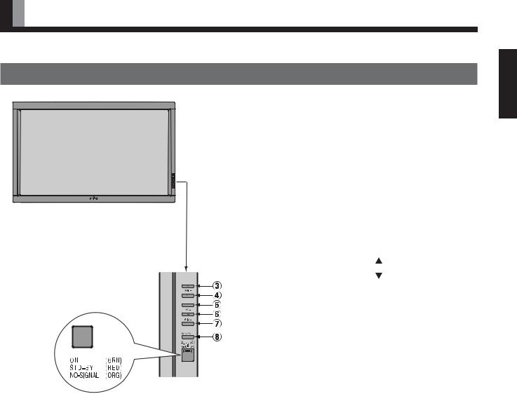
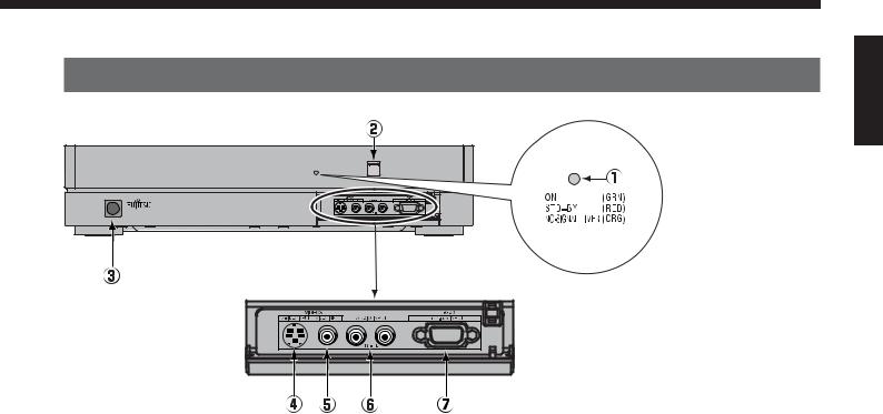
DISPLAY SECTION – FRONT
(Right section)


Control Panel (Right side of display)
1Power indicator lamp
This lamp shows the state of the power supply.
|
Lit (red): |
Stand-by |
|
|
Lit (green): |
Power ON |
|
|
Lit (orange): |
Power saving (DPMS: Power saving |
|
|
|
function) mode ON (See P. E-42.) |
|
|
Flashing (red): Malfunction (Flashes differently depending |
||
|
|
on the type of malfunction. See P. E-50 for |
|
|
|
more information.) |
|
2 |
Remote control signal receiver |
||
|
Receives signals from the remote |
. |
|
3 |
Input mode selector |
|
|
4 |
Input mode selector |
[MODE] |
|
|
Switches between picture input modes. |
||
5 |
VOL + button |
|
|
6VOL – button
Adjusts the sound volume.
7Wide screen selector button [WIDE]
Switches the screen over to a desired wide screen.
8ON/OFF button
Turns the power “ON” and “OFF (standby state)”.
Warning
If the power indicator lamp flashes red, this signifies that the display has developed a problem. When this happens, be sure to remove the power plug from the receptacle and contact your dealer. Leaving the display power ON can result in fire or electric shock.
E-7
English
PART NAMES AND FUNCTIONS (Continued)
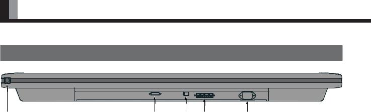
DISPLAY SECTION – LOWER PART
|
|
|
|
1 power switch
When pressed while in the “OFF” state, the power indicator lamp lights and the display is placed in the “ON  ” state, and the power can be turned “ON” or “OFF” by the remote control or on the control panel of the display. When pressed while in the “ON
  ” state, the power indicator lamp goes out and the display is placed in the “OFF” state.
2Display input (picture) terminal
Connect this terminal to the display output terminal on the tuner using the special cable provided.
3 Display input (audio) terminal
Connect this terminal to the display output terminal on the tuner using the special cable provided.
4 External speaker output terminal (EXT SP)
Connect this terminal to the optionally available speaker.
When connecting a cable, attach a ferrite core to the cable. (See P. E-15.) *See the speaker instruction manual for more information.
5Power input terminal
Connect this terminal to the power cable supplied with the display.
E-8
SELECTOR SECTION – FRONT
English
1Power indicator lamp
This lamp shows the state of the power supply.
Lit (red): |
Stand-by |
Lit (green): Power ON
Lit (orange): Power saving (DPMS: Power saving function) mode ON (See P. E-42.)
Flashing (red): Malfunction (Flashes differently depending on the type of malfunction. See P. E-50 for more information.)
2 Remote control signal receiver
Receives signals from the remote control.
3POWER button
Turns the power “ON” and “OFF”.
* Even when the power is “OFF”, some parts are still powered.
4Video3, S-video input terminal *
Connect this terminal to the S-video output terminal of your VCR, etc.
5 Video3, video input terminal *
Connect this terminal to the video output terminal of your VCR, etc.
6Audio input terminals (L/R)
These are the audio input terminals for the Video3 and RGB3 terminals.
Input the audio for the video to be seen here.
7RGB3 input terminal
Connect this terminal to your PC’s mD-sub output terminal.
* On selecting the video input format
(See “SETTING THE INPUT TERMINALS” on P. E-41.)
Warning
If the power indicator lamp flashes red, this signifies that the display has developed a problem. When this happens, be sure to remove the power plug from the receptacle and contact your dealer. Leaving the display power ON can result in fire or electric shock.
E-9
PART NAMES AND FUNCTIONS (Continued)
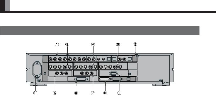
SELECTOR SECTION – REAR
|
|
VIDEO1 |
|
VIDEO2 |
|
VIDEO4 |
VIDEO5 |
|
VIDEO6 |
RGB1 |
RGB2 |
|
|
|
AUDIO |
|
|
|
|
|
|
|
|
|
|
|
|
|
AUDIO |
INPUT |
|
|
|
|
|
|
|
|
|
|
|
|
|
OUTPUT |
|
|
|
|
|
|
|
|
|
|
|
DIGITAL1 |
DIGITAL2 |
DIGITAL |
|
|
|
|
|
VIDEO1 |
|
|
VIDEO2 |
|
|
|
|
VIDEO4 |
|
|
|
|
COMPONENT VIDEO |
S |
|
|
COMPONENT VIDEO |
S |
|
|
COMPONENT VIDEO |
S |
|
||
PICTURE |
Y |
PB/CB |
PR/CR |
|
Y |
PB/CB PR/CR |
|
Y |
PB/CB |
PR/CR |
|
|
||
|
|
|
VIDEO5 |
|
|
VIDEO1 |
|
|
|
|
RGB2 |
|
||
INPUT |
COMPONENT VIDEO |
|
|
|
COMPONENT VIDEO |
|
|
|
mD-sub |
|
|
|||
|
|
Y |
|
PB/CB |
PR/CR |
RGB1 |
Y |
PB/CB |
PR/CR |
|
|
|
|
|
|
|
|
|
|
|
|
|
|
|
|
|
PICTURE |
AUDIO |
|
|
|
|
|
|
|
DVI |
|
|
|
|
|
|
||
|
|
|
|
|
|
|
|
|
DISPLAY OUTPUT |
|
|
|
||
|
|
|
|
|
|
|
|
|
|
|
|
|
||
1Audio input terminals
Input audio through the terminals corresponding to the used video input terminals.
* The digital input terminals can be matched as desired with the remote control. (See P. E-27.)
2 Audio output terminals
For use when the sound from an audio system (amplifier) is used.
3 Video1 input terminal
4 Video2 input terminal
5Video4 input terminal
Connect this terminal to the component video output terminal, S-video output terminal, or video output terminal of your VCR or DVD, etc.
* See “SETTING THE INPUT TERMINALS” on P. E-41.
6 Video5 input terminal
7 Video6 input terminal
Connect this terminal to the component video output terminal of your DVD, etc.
8 RGB1 input terminal
Connect this terminal to the monitor (DVI-D) output terminal of your PC.
9 RGB2 input terminal
Connect this terminal to the monitor (mD-sub) output terminal of your PC.
0Display output terminals (Picture/Audio)
Connect these terminals to the picture input terminal and audio input terminals on the display.
APower input terminal
Connect this terminal to the power cable supplied with the display.
E-10
Description of Input Terminals
DVI-D terminal (RGB 1 INPUT/DVI-D)
RGB2 input terminal (RGB2, 3 INPUT/mD-sub)
|
|
|
|
|
|
|
|
|
|
|
|
|
|
|
|
|
|
|
|
|
|
|
|
|
|
|
|
|
|
|
|
|
|
|
|
|
|
|
|
|
|
|
|
|
|
|
|
|
|
|
|
|
|
|
|
|
|
|
|
|
|
|
|
|
|
|
|
|
|
|
|
|
|
|
|
|
|
|
|
|
|
|
|
|
|
|
|
|
|
|
|
|
|
|
|
|
|
|
|
|
|
|
|
|
|
|
|
|
|
|
|
|
|
|
|
|
|
|
|
|
|
|
|
|
|
|
|
|
|
|
|
|
|
|
|
|
|
|
|
|
|
|
|
|
|
|
|
|
|
|
|
|
|
|
|
|
|
|
|
|
|
|
|
|
|
|
|
|
|
|
|
|
|
|
|
|
|
|
|
|
|
|
|
|
|
|
|
|
|
|
|
|
|
|
|
|
|
|
|
|
|
|
|
|
|
|
|
|
|
|
|
|
|
|
|
|
|
|
|
|
|
|
|
|
|
|
|
|
|
|
|
|
|
|
|
|
|
|
|
|
|
|
|
|
|
|
|
|
|
|
|
|
|
|
|
|
|
|
|
|
|
|
|
|
|
|
|
|
|
|
|
|
|
|
|
|
|
|
|
|
|
|
|
|
|
|
|
|
|
|
|
|
|
|
|
|
|
|
|
|
|
|
|
|
|
|
|
|
|
|
|
|
|
|
|
|
|
|
|
|
|
|
|
|
|
|
|
|
|
|
|
|
|
|
|
|
|
|
|
|
|
|
|
|
|
|
|
|
|
|
|
|
|
|
|
|
|
|
|
|
|
|
|
|
|
|
|
|
|
|
|
|
|
|
|
|
|
|
|
|
|
|
|
|
|
|
|
|
|
|
|
|
|
|
|
|
|
|
|
|
|
|
|
|
|
|
|
|
|
|
|
|
|
|
|
|
|
|
|
|
|
|
|
|
|
|
|
|
|
|
|
|
|
|
|
|
|
|
|
|
|
|
|
|
|
|
|
|
|
|
|
|
|
|
|
|
|
|
|
|
|
|
|
|
|
|
|
|
|
|
|
|
|
|
|
|
|
|
|
|
|
|
|
|
|
|
|
|
|
|
|
|
|
|
|
|
|
|
|
|
|
|
|
|
|
|
|
|
|
|
|
|
|
|
|
|
|
|
|
|
|
|
|
|
|
|
|
|
|
|
|
|
|
|
|
|
|
|
|
|
|
|
|
|
|
|
|
|
|
|
|
|
|
|
|
|
|
|
|
Pin No. |
Input signal |
Pin No. |
|
|
|
|
Input signal |
||||||||||||||||||||
1 |
|
|
Red |
9 |
|
|
|
— |
|||||||||||||||||||
|
|
|
|
|
|
|
|
|
|
|
|
|
|
|
|
|
|
|
|
|
|
|
|
|
|
|
|
2 |
|
|
Green |
10 |
|
|
Ground |
||||||||||||||||||||
|
|
|
|
|
|
|
|
|
|
|
|
|
|
|
|
|
|
|
|
|
|
|
|
|
|
|
|
3 |
|
|
Blue |
11 |
|
|
— |
||||||||||||||||||||
|
|
|
|
|
|
|
|
|
|
|
|
|
|
|
|
|
|
|
|
|
|
|
|
|
|
|
|
4 |
|
|
— |
12 |
|
|
— |
||||||||||||||||||||
|
|
|
|
|
|
|
|
|
|
|
|
|
|
|
|
|
|
|
|
|
|
|
|
|
|
|
|
5 |
|
|
Ground |
13 |
|
|
Horizontal synchronization |
||||||||||||||||||||
|
|
|
|
|
|
|
|
|
|
|
|
|
|
|
|
|
|
|
|
|
|
|
|
|
|
|
|
6 |
|
|
Ground |
14 |
|
|
Vertical synchronization |
||||||||||||||||||||
|
|
|
|
|
|
|
|
|
|
|
|
|
|
|
|
|
|
|
|
|
|
|
|
|
|
|
|
7 |
|
|
Ground |
15 |
|
|
— |
||||||||||||||||||||
|
|
|
|
|
|
|
|
|
|
|
|
|
|
|
|
|
|
|
|
|
|
|
|
|
|
|
|
8 |
|
|
Ground |
Frame |
Ground |
||||||||||||||||||||||
|
|
|
|
|
|
|
|
|
|
|
|
|
|
|
|
|
|
|
|
|
|
|
|
|
|
|
|
English
E-11
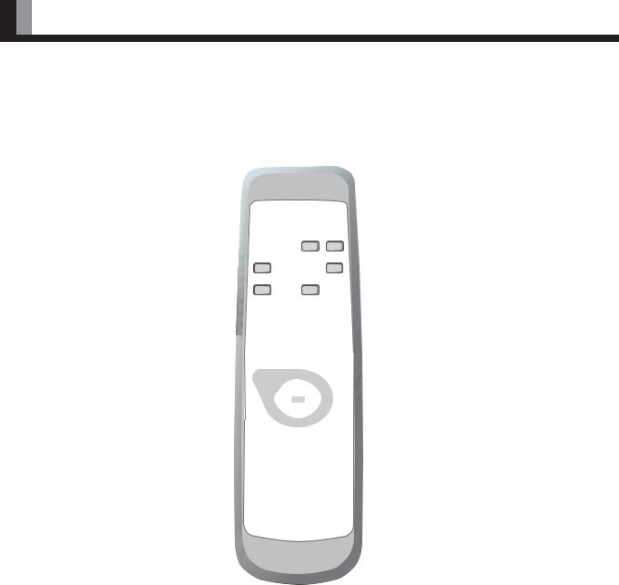
PART NAMES AND FUNCTIONS (Continued)
REMOTE CONTROL
For details, see page |
. |
1 button
Switches between power ON and standby state.
4 DISPLAY OFF button 
For showing on-screen-information.
5 PICTURE MODE button 
Switches the picture mode.
8 AUDIO IN button 
Selects the input audio.
0 Video input mode selector button
[VIDEO 1 – 6] 
Selects VIDEO 1 – 6
A RGB input mode selector button
[RGB 1 – 3] 
Selects RGB 1 – 3.
CMenu button [MENU]  –
– 
Use this button to display a desired menu for adjusting the picture.
D Enter button [ENTER]  –
– 
Press this button to finalize the selection of a desired menu or option within a menu.
2STILL button 
Displays a still picture during viewing.
3MUTE button 
Temporarily mutes the sound.
6 PICTURE MEMORY button 
Recalls the PICTURE MEMORY.
7 WIDE button 
Switches the screen over to a desired wide screen.
9 OFF-TIMER 
Sets when the power should be turned off.
BVolume adjustment buttons [VOL +/– ] 
Adjust the volume.
Press the + button to increase the volume. Press the – button to reduce the volume.
E Adjustment buttons [  /
/  /
/  /
/  ]
]
 –
– 
Use these buttons to scroll through options in a menu.
E-12
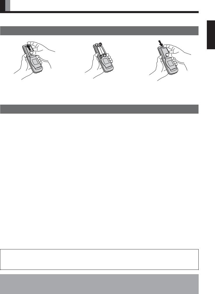
USING THE REMOTE CONTROL
PUTTING BATTERIES IN THE REMOTE CONTROL
English
1To remove the cover, slide it outwards while pressing it down.
2Place two AA batteries in the remote control. Make sure that the batteries are properly oriented.
3Close the cover until it snaps into place.
PRECAUTIONS
To prevent malfunction, be sure not to apply any form of severe shock to the remote control.
To prevent malfunction or deformation, be sure not to allow the remote control to become wet; also, keep it away from hot locations or heating equipment.
Be sure not to clean the remote control using a cloth dampened in any volatile solvent, such as benzene or thinner.
CAUTION: Be sure to use replacement batteries of the same type as the original ones.
When disposing of used batteries, please comply with governmental regulations or environmental public institution’s rules that apply in your country/area.
Note
The remote control will not function properly if the batteries are dead. Be sure to replace them as needed.
Do not use rechargeable batteries (Ni-Cd).
E-13
USING THE REMOTE CONTROL (Continued)
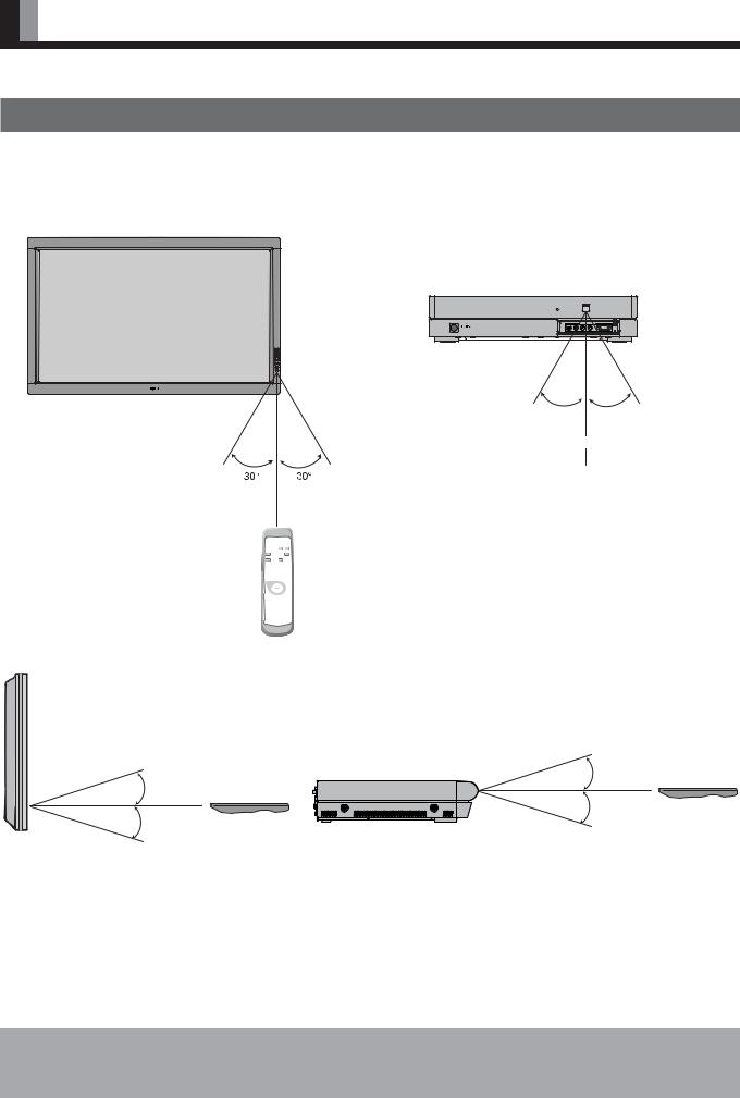
EFFECTIVE RANGE FOR THE REMOTE CONTROL
Point the remote control at the display’s signal receiver when using it.
Make sure that there are no obstacles between the remote control and the display’s signal receiver.
|
Left |
Right |
|
|
5 m (Front) |
Left |
Right |
|
|
5 m (Front) |
|
Display – front
Selector – front
Upper
Upper
Lower
Lower
Selector – side
Display – side
Information
The remote control may not function properly if you use a high-frequency fluorescent lamp. If you experience problems, move the lamp or use the remote control from a different position.
E-14
CONNECTING THE DISPLAY TO EXTERNAL EQUIPMENT
Be sure to turn OFF the power to the display and external equipment before making any connections.
No cables are supplied with the display for connection to external equipment. The type of cable to be used varies depending on the PC model. Contact your dealer for more information.
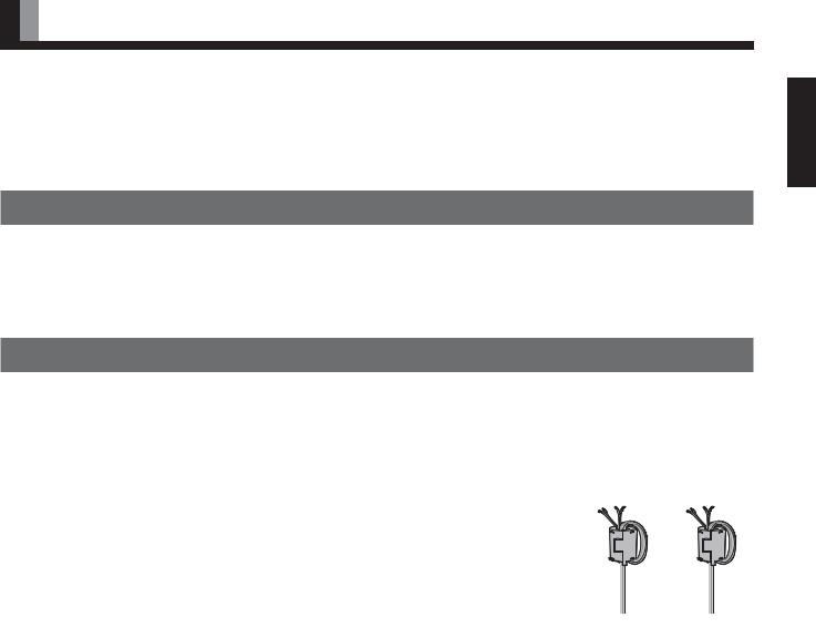
RECEPTACLE
Make sure that the power cable’s grounding wire is grounded.
The display comes with a 3-prong power plug; one prong is connected to the grounding wire. If you have only a 2-hole receptacle, you will need to have it replaced. Contact your dealer for more information.
CONNECTING THE DISPLAY TO EXTERNAL EQUIPMENT
Carefully check the terminals for position and type before making any connections.
Loose connectors can result in picture or color problems. Make sure that all connectors are securely inserted into their terminals.
Ferrite cores
These ferrite cores are used to attenuate undesired signals.
• 2 ferrite cores
When connecting a cable to the external speaker output terminal, attach a ferrite core to the cable near the terminal as illustrated on the right.
E-15
English
 Loading...