

Page 1

C156-E228-02EN
MCM3064SS, MCM3130SS
MCP3064SS, MCP3130SS
OPTICAL DISK DRIVES
PRODUCT MANUAL
Page 2

FOR SAFE OPERATION
Handling of This Manual
This manual contains important info rmat ion for usi ng this produc t. Read thoroughly befor e using
the product. Use this product only after thoroughly reading and understanding especially the
section "Important Alert Items" in this manual. Keep this manual handy, and keep it carefully.
FUJITSU makes every effort to prevent users and bystanders from being injured or from suffering
damage to their property. Use the product according to this manual.
This product is designed and manufactured for use in standard applications such as office work,
personal devices and household appliances. This product is not intended for special uses (atomic
controls, aeronautic or space systems, mass transport vehicle operating controls, medical devices for
life support, or weapons firing controls) where particularly high reliability requirements exist,
where the pertinent levels of safety are not guaranteed, or where a failure or operational error could
threaten a life or cause a physical injury (herea ft er ref e rred to as "miss ion -c ri tic al " use). Customers
considering the use of these products for mission-critical applications must have safety-assurance
measures in place beforehand. Moreover, they are requested to consult our sales representative
before embarking on such specialized use.
Fujitsu Limited assumes no liability for data loss or damage that might occur as a result of using
this product. To help prevent such loss or damage that might occur in rare cases, back up the data
as appropriate.
Second Edition January, 2004
The contents of this manual may be revised without prior notice.
The contents of this manual shall not be disclosed in any way or reproduced in any media without
the express written permission of Fujitsu Limited.
All Rights Reserved, Copyright FUJITSU LIMITED 2002, 2004
Page 3

Revision History
(1/1)
Edition Date
Revised section (*1)
(Added/Deleted/Altered)
Details
01 March, 2002 — —
02 January, 2004 — —
*1 Section(s) with asterisk (*) refer to the previous edition when those were deleted.
C156-E228-02EN
Page 4

This page is intentionally left blank.
Page 5

Preface
This manual describes the MCM3064SS, MCM3130SS, MCP3064SS and MCP3130SS
3.5-inch optical disk drives.
This manual provides an overview of the above optical disk drives, and explains their
specifications, the requirements and procedures for installing them in a system, and how to
clean them.
The manual is intended for users who have a basic understanding of optical disk drives and
their use in computer systems.
See "Manual Organization" for details of the organization of manuals related to optical
disk drives and the scope of this manual. Use the other manuals shown in "Manual
Organization" together with this manual when necessary.
The organization of this manual, related reference manual and conventions for alert
messages follow.
Overview of Manual
This manual consists of the following six chapters, glossary, and abbreviation:
Chapter 1 General Description
This chapter introduces the MCM3064SS, MCM3130SS, MCP3064SS and MCP3130SS
optical disk drives and describes their features, drive configuration, and system
configuration.
Chapter 2 Specifications
This chapter describes the specifications of the MCM3064SS, MCM3130SS, MCP3064SS
and MCP3130SS optical disk drives and the specifications of optical disk cartridges.
Chapter 3 Installation Requirements
This chapter describes the basic environmental, mounting, power supply, and connection
requirements for installing the MCM3064SS, MCM3130SS, MCP3064SS and
MCP3130SS optical disk drives in a user system.
Chapter 4 Installation
This chapter describes installation of the MCM3064SS, MCM3130SS, MCP3064SS and
MCP3130SS optical disk drive and includes:
• Notes on handling the drive
• Connection modes
• Settings
• Mounting
• Cable connections
• Operation, confirmation, and preparation for use after installation
C156-E228-02EN i
Page 6

Preface
• Notes on removing the installed drive
Chapter 5 Operation and Cleaning
This chapter describes how to operate and clean MCM3064SS, MCM3130SS,
MCP3064SS and MCP3130SS optical disk drives. This chapter also describes how to
operate and clean optical disk cartridges.
Chapter 6 Diagnostics and Maintenance
This chapter describes the self-diagnostics functions and maintenance of the MCM3064SS,
MCM3130SS, MCP3064SS and MCP3130SS optical disk drives.
Chapter 7 SCSI BUS
This chapter describes in detail the configuratio n, physical/electrical conditions, interface
protocol and operation of the SCSI (Small Computer System Interface), which is an
interface for connecting the MCM3064SS, MCM3130SS, MCP3064SS and MCP3130SS
optical disk drive and the user system to each other.
Glossary
The glossary describes the technical terms that need to be understood to read this manual.
Acronyms and Abbreviations
This manual contains a list of the abbreviations used in this manual and their meanings.
CONVENTIONS USED IN THIS MANUAL
Throughout this manual, the MCM3064SS, MCM3130SS, MCP3064SS and MCP3130SS
optical disk drives are described as an "ODD," "drive," "unit," "target (TARG)," or
"device."
Decimal values are indicated without any modifiers added.
Hexadecimal values are indicated as X'17B9', 17B9h, 17B9H, and 17B9H.
Binary values are indicated as "010" and 010b.
If "BUSY LED" is described in this manual, this re f ers to the LED that is located on the
front side (cartridge-loading side) and that indicates the BUSY state of the device. It is
described as "LED on the front panel."
ii C156-E228-02EN
Page 7

Preface
Conventions for Alert Messages
This manual uses the following conventions to show the alert messages. An alert message
consists of an alert signal and alert statements. The alert signal consists of an alert symbol
and a signal word or just a signal word.
The following are the alert signals and their meanings:
This indicates a hazardous situation likely to result in
serious personal injury if the user does not perform the
procedure correctly.
This indicates a hazardous situation could result in serious
personal injury if the user does not perform the procedure
correctly.
This indicates a hazardous situation could result in minor
or moderate personal injury if the user does not perform
the procedure correctly. This alert signal also indicates
that damages to the product or other property, may occur if
the user does not perform the product correctly.
This indicates information that could help the user use the
product more efficiently.
Attention
In the text, the alert signal is centered, followed below by the indented message. A wider
line space precedes and follows the alert message to show where the alert message begins
and ends. The following is an example:
(Example)
While the write cache feature is enabled, a write error is reported in the
completion status of another command that is subsequent to the concerned
write command. Note that, if the host performs only retry of an errorreporting command, data in the block in which the error has occurred is not
correctly written.
The main alert messages in the text are also listed in the “Important Alert Items.”
Please forward any comments you may have regarding this manual.
To make this manual easier for users to understand, opinions from readers are needed.
Please write your opinions or requests on the Comment at the back of this manual and
forward it to the address described in the sheet.
C156-E228-02EN iii
Page 8

This page is intentionally left blank
Page 9

Important Alert Items
Important Alert Messages
The important alert messages in this manual are as follows:
A hazardous situation could result in minor or moderate personal injury if the
user does not perform the procedure correctly. Also, damage to the product
or other property, may occur if the user does not perform the procedure
correctly.
Task Alert message Page
Installation
Data loss: Data is not guaranteed if a power failure occurs or the I/F
cable is pulled out while:
• Data is being written to a data block
• A disk is being initialized (formatted)
• Defect processing is in progress
Data is not guaranteed either if the drive is moved with the optical disk
cartridge inserted or the drive is exposed to excessive shock or
vibration.
Data loss: When the verify function is invalid, the write data quality is
not guaranteed. This mode should not be used for storing important
data. When using the mode for storing important data, a preventive
system measure such as file duplication is required.
1) Shock or vibration applied to the drive that exceeds the values
defined in the standard damage the drive. Use care when
unpacking.
2) Do not leave the drive in dirty or contaminated environments.
3) Since static discharge may destroy the CMOS devices in the drive,
pay attention to the following points after unpacking:
• Use an antistatic mat and wrist strap when handling the drive.
• Hold the mounting frame when handling th e drive. Do not
touch the PCA except when setting the switches.
2-6
3-23
4-1
4) When handling the drive, hold both sides of the mounting frame.
When touching other than both sides of the mounting frame, avoid
putting force.
5) Do not forcibly push up the end of the header pin of the printed
circuit board unit when handling or setting the drive.
C156-E228-02EN v
Page 10

Important Alert Items
Task Alert message Page
Installation
Before moving the drive, remove the optical disk cartridge. If the drive is
moved with the optical disk cartridge loaded in it, the head may move
back and forth in the drive to damage the head or disk and reading the
data may fail
1) The user must not change the settings of terminals not described in
this section. The terminals must remain as set when shipped.
2) Do not change terminal settings when the power is on.
3) To strap setting terminals, use the jumper shipped with the drive.
1) Make sure that the system power is off.
2) Do not connect or disconnect any cable when the power is on.
1) Be careful of the insertion directions of SCSI connectors. For a
system in which the terminating resistor power is supplied via the
SCSI cable, connecting connectors in the wrong direction may cause
the following:
The overcurrent protection fuse of the terminating resistor power
supply (SCSI device) may blow when power is turned on.
The cable may burn if overcurrent protection is not provided.
2) Be careful of cable connector positions when connecting more than
one SCSI device. The SCSI device having the terminating resistor
must be connected to the end of the cable.
3) The cables must be kept away from the rotating part of the spindle
motor.
4-2
4-5
4-13
4-14
Cleaning cartridge
Maintenance and Repair
Before demounting the optical disk drive, turn off the system power. Do
not remove screws securing the cables and drive when the power is on.
Device Damage: Be sure to use the dedicated head cleaner shown
above.
Disk damage: To clean a disk, use the cleaning solution and cleaning
cloth specified in Table 5.2.
Disk damage: Do not use this cleaning kit on a floppy disk or an
optical disk cartridge to be used on other optical disk drives.
Disk damage: Clean a cartridge in a dust-free environment.
Fujitsu recommends wearing disposable gloves during cleaning so that
no fingerprints are left on a disk.
Disk damage: Do not press hard or apply excessive shock to an optical
disk cartridge case while setting it in the settin g case.
Eye inflammation: If the cleaning so lution gets into your eyes,
immediately wash the solution away with water.
Data loss: For a repair request, you normally do not need to include
any optical disk cartridge with an optical disk drive. However, you do
need to include a cartridge if errors keep occurring with a specific
cartridge. In such a case, be sure to save data stored in the cartridge
before sending it in. Fujitsu shall bear no responsibility for any data lost
during service or repair.
4-17
5-6
5-10
5-11
5-11
5-12
5-13
6-3
vi C156-E228-02EN
Page 11

MANUAL ORGANIZATION
OPTICAL DISK DRIVES
1. GENERAL DESCRIPTION
PRODUCT MANUAL
(C156-E228)
<This manual>
OPTICAL DISK DRIVES
SCSI Logical Specifications
(C156-E092)
2. SPECIFICATIONS
3. INSTALLATION REQUIREMENTS
4. HOST INTERFACE
5. OPERATION AND CLEANING
6. DIAGNOSTICS AND MAINTENANCE
1. COMMAND PROCESSING
2. DATA BUFFER MANAGEMENT
3. COMMAND SPECIFICATIONS
4. SENSE DATA AND ERROR RECOVERY
5. SCSI MESSAGES
6. ERROR RECOVERY
C156-E228-02EN vii
Page 12

REFERENCED STANDARDS
The product specifications and functions described in this manual conform to the following
standards:
Specification
(document) number
ANSI X3.131-1986 American National Standard for Information
System - small ComputerSystem Interface (SCSI)
ANSI X3.131-1994 American National Standard for Information
System - small ComputerSystem Interface-2 (SCSI-2)
ISO/IEC 10090 90mm Optical Disk Cartridges, rewritable and read
only, for data interchange.
ISO/IEC 13963 Data Interchange on 90mm Optical Disk cartridges
Capacity: 230 megabytes per cartridges.
ISO/IEC 15041 Data Interchange on 90mm Optical Disk Cartridges
Capacity: 640 megabytes per cartridges.
Cherry Book Version
1.0
GIGAMO 1.3GB 90mm Magneto-Optical Disk
System.
Name Concerned organization
*1 ISO= International Organization for Standardization
IEC= International Electri cal fo r C omm is sion
JTC1= Joint Technical Committee 1
American National
Standards Institute (ANSI)
American National
Standards Institute (ANSI)
ISO/IEC (*1)
ISO/IEC (*1)
ISO/IEC JTC1 (*1)
FUJITSU LIMITED
SONY CORPORATION
viii C156-E228-02EN
Page 13

Contents
CHAPTER 1 General Description................................................................ 1-1
1.1 Features.....................................................................................................1-1
1.1.1 Performance and Functions................................................................. 1-1
1.1.2 Reliability............................................................................................1-3
1.1.3 Maintainability/operability .................................................................1-3
1.1.4 Adaptability......................................................................................... 1-3
1.1.5 Interface...............................................................................................1-4
1.2 Configuration of Optical Disk Drive........................................................1-6
1.2.1 Appearance.......................................................................................... 1-6
1.2.2 Configuration ...................................................................................... 1-7
1.2.3 Mechanical section.............................................................................. 1-7
1.2.4 Control circuit section......................................................................... 1-8
CHAPTER 2 Specifications ......................................................................... 2-1
2.1 Specifications of Optical Disk Drives...................................................... 2-1
2.1.1 Catalog and order numbers .................................................................2-1
2.1.2 Specifications of drives....................................................................... 2-2
2.1.3 Environmental and power requirements.............................................2-4
2.1.4 Error rate ............................................................................................. 2-5
2.1.5 Reliability............................................................................................2-6
2.2 Specifications of Optical Disk Cartridges................................................ 2-7
2.2.1 Recommended optical disk cartridges ................................................2-7
2.2.2 Appearance.......................................................................................... 2-8
2.2.3 Specifications of disk........................................................................2-10
2.3 Defect Management................................................................................2-11
2.3.1 Defect management schematic diagram ........................................... 2-11
CHAPTER 3 Installation Requirements...................................................... 3-1
3.1 Environmental Requirements...................................................................3-1
C156-E228-02EN ix
Page 14

Contents
3.1.1 Temperature measurement points........................................................3-1
3.1.2 Temperature requirements...................................................................3-2
3.1.3 Temperature rise..................................................................................3-3
3.1.4 Air flow ...............................................................................................3-4
3.1.5 Air cleanliness.....................................................................................3-4
3.2 Mounting Requirements ...........................................................................3-4
3.2.1 Outer dimensions.................................................................................3-4
3.2.2 Installation direction..........................................................................3-10
3.2.3 Center of gravity................................................................................3-11
3.2.4 Precautions on mounting...................................................................3-12
3.3 Power Supply Requirements...................................................................3-14
3.4 Connection Requirement ........................................................................3-17
3.4.1 Connectors and terminals..................................................................3-17
3.4.2 Cable connection requirements.........................................................3-19
3.4.3 External operator panel .....................................................................3-20
3.4.4 External operator panel settings (CNH2)..........................................3-23
CHAPTER 4 Installation ...............................................................................4-1
4.1 Notes on Drive Handling..........................................................................4-1
4.2 Connection Modes....................................................................................4-4
4.3 Settings......................................................................................................4-5
4.3.1 Setting switches (SW1).......................................................................4-7
4.3.2 Setting of supplying power to SCSI terminating resistor..................4-10
4.3.3 SCSI terminating resistor mode.........................................................4-11
4.4 Mounting.................................................................................................4-12
4.4.1 Checks before mounting the drive.....................................................4-12
4.4.2 Mounting procedure ..........................................................................4-13
4.5 Cable Connections..................................................................................4-13
4.6 Operation Confirmation and Preparation for Use after Installation.......4-14
4.6.1 Confirming initial operations............................................................4-14
4.6.2 SCSI connection check......................................................................4-15
4.7 Dismounting Drive..................................................................................4-17
x C156-E228-02EN
Page 15

Contents
CHAPTER 5 Operation and Cleaning ......................................................... 5-1
5.1 Operation of Optical Disk Drive ..............................................................5-1
5.1.1 Appearance of optical disk drive ........................................................5-1
5.1.2 Precautions..........................................................................................5-2
5.1.3 Inserting an optical disk cartridge.......................................................5-2
5.1.4 Removing an optical disk cartridge .................................................... 5-4
5.2 Cleaning of Optical Disk Drive................................................................5-5
5.3 Operation of Optical Disk Cartridge ........................................................5-6
5.3.1 Appearance.......................................................................................... 5-6
5.3.2 Write protect tab..................................................................................5-8
5.3.3 Precautions..........................................................................................5-9
5.4 Cleaning the Optical Disk Cartridge ......................................................5-10
5.4.1 Cleaning tool for optical disk cartridge ............................................5-10
5.4.2 Cleaning of optical disk cartridge.....................................................5-11
CHAPTER 6 Diagnostics and Maintenance ............................................... 6-1
6.1 Diagnostics ...............................................................................................6-1
6.1.1 Initial self-diagnostics......................................................................... 6-1
6.1.2 Diagnostic command........................................................................... 6-2
6.1.3 Test program ....................................................................................... 6-2
6.2 Maintenance Information .........................................................................6-2
6.2.1 Maintenance requirements..................................................................6-2
6.2.2 Revision number ................................................................................. 6-3
CHAPTER 7 SCSI BUS................................................................................. 7-1
7.1 System Configuration...............................................................................7-1
7.2 Interface Signal Definition.......................................................................7-3
7.3 Physical Requirements .............................................................................7-6
7.3.1 Interface connector.............................................................................. 7-6
7.3.2 Interface cable.....................................................................................7-9
C156-E228-02EN xi
Page 16

Contents
7.4 Electrical Requirements..........................................................................7-11
7.4.1 SCSI interface....................................................................................7-11
7.4.2 Power supply for terminating resistor...............................................7-12
7.4.3 Signal driving conditions...................................................................7-13
7.5 Timing Rule............................................................................................7-15
7.6 Bus Phases ..............................................................................................7-18
7.6.1 BUS FREE phase...............................................................................7-18
7.6.2 ARBITRATION phase......................................................................7-20
7.6.3 SELECTION phase ...........................................................................7-22
7.6.4 RESELECTION phase......................................................................7-24
7.6.5 INFORMATION TRANSFER phases..............................................7-26
7.6.6 COMMAND phase............................................................................7-33
7.6.7 DATA phase......................................................................................7-33
7.6.8 STATUS phase..................................................................................7-36
7.6.9 MESSAGE phase ..............................................................................7-36
7.6.10 Signal requirements concerning transition between bus phases.......7-37
7.6.11 Time monitoring feature....................................................................7-38
7.7 Bus Conditions........................................................................................7-40
7.7.1 ATTENTION condition ....................................................................7-40
7.7.2 RESET condition...............................................................................7-42
7.8 Bus Sequence..........................................................................................7-45
Glossary .......................................................................................................GL-1
Acronyms and Abbreviations.......................................................................AB-1
Index ............................................................................................................... IN-1
xii C156-E228-02EN
Page 17

Contents
Illustrations
FIGURES
Figure 1.1 The optical disk drive (with panel)............................................. 1-6
Figure 1.2 The optical disk drive (without panel)........................................1-6
Figure 1.3 Configuration of optical disk drive.............................................1-7
Figure 1.4 Block diagram of the control circuit section...............................1-9
Figure 2.1 Optical disk cartridge .................................................................2-8
Figure 2.2 Algorithms for alternate processing..........................................2-11
Figure 2.3 Example of alternate processing............................................... 2-12
Figure 3.1 Surface temperature measurement point ...................................3-1
Figure 3.2 Outer dimensions .......................................................................3-5
Figure 3.3 Outer dimensions .......................................................................3-7
Figure 3.4 Installation directions................................................................ 3-10
Figure 3.5 Center of gravity.......................................................................3-11
Figure 3.6 Mounting frame structure ......................................................... 3-12
Figure 3.7 Service areas ............................................................................. 3-13
Figure 3.8 MCM3130SS current waveform (+5 VDC) ............................. 3-14
Figure 3.9 Power on/off sequence (1)........................................................3-15
Figure 3.10 Power on/off sequence (2) ........................................................3-15
Figure 3.11 Power on/off sequence (3) ........................................................3-15
Figure 3.12 AC noise filter (recommended) ................................................ 3-16
Figure 3.13 Connector and terminal locations .............................................3-17
Figure 3.14 Power supply connector............................................................ 3-18
Figure 3.15 Cable connection mode.............................................................3-19
Figure 3.16 External operator panel circuit example...................................3-21
Figure 3.17 External operator panel interface connector.............................3-22
Figure 4.1 Individual packaging style..........................................................4-3
Figure 4.2 Gathered packaging style............................................................4-3
Figure 4.3 SCSI bus connection modes .......................................................4-4
Figure 4.4 Positions of setting terminals and switches................................4-6
Figure 4.5 Setting switch (SW1)..................................................................4-7
Figure 4.6 SCSI connection check .............................................................4-16
Figure 5.1 Optical disk drive front view (with panel).................................. 5-1
C156-E228-02EN xiii
Page 18

Contents
Figure 5.2 Inserting an optical disk cartridge...............................................5-3
Figure 5.3 Removing an optical disk cartridge ............................................5-5
Figure 5.4 Appearance of optical disk cartridge ..........................................5-7
Figure 5.5 Write protect tab..........................................................................5-8
Figure 5.6 Opening a shutter ......................................................................5-11
Figure 5.7 Setting an optical disk cartridge into the setting case...............5-12
Figure 5.8 Placing the setting case cover ...................................................5-12
Figure 5.9 Cleaning of disk surface............................................................5-13
Figure 6.1 Revision label..............................................................................6-3
Figure 6.2 Revision number indication ........................................................6-4
Figure 7.1 Example of SCSI configuration..................................................7-2
Figure 7.2 Interface signals ..........................................................................7-3
Figure 7.3 DATA BUS and SCSI ID............................................................7-4
Figure 7.4 SCSI interface connector (ODD side).........................................7-6
Figure 7.5 SCSI interface connector (cable side).........................................7-7
Figure 7.6 SCSI interface connector pin assignments (single-ended type)..7-8
Figure 7.7 Connection of interface cable....................................................7-10
Figure 7.8 SCSI termination circuit............................................................7-12
Figure 7.9 BUS FREE phase ......................................................................7-19
Figure 7.10 ARBITRATION phase..............................................................7-21
Figure 7.11 SELECTION phase...................................................................7-23
Figure 7.12 RESELECTION phase..............................................................7-25
Figure 7.13 INFORMATION TRANSFER phase (phase control) ..............7-27
Figure 7.14 Transfer in asynchronous mode ................................................7-29
Figure 7.15 Transfer in synchronous mode..................................................7-32
Figure 7.16 Data transfer rate in asynchronous mode..................................7-34
Figure 7.17 Data transfer rate in synchronous mode....................................7-35
Figure 7.18 Switching direction of transfer over the data bus .....................7-38
Figure 7.19 ATTENTION condition............................................................7-42
Figure 7.20 RESET condition.......................................................................7-44
Figure 7.21 Bus phase sequence...................................................................7-46
Figure 7.22 Example of bus phase transition on execution
of a single command ................................................................7-48
xiv C156-E228-02EN
Page 19

Contents
TABLES
Table 2.1 Representative model names and order numbers ....................... 2-1
Table 2.2 Specifications.............................................................................. 2-2
Table 2.3 Environmental and power requirements ....................................2-4
Table 2.4 Recommended optical disk cartridges........................................2-7
Table 2.5 Disk specifications....................................................................2-10
Table 3.1 Temperature requirements at measurement points..................... 3-2
Table 3.2 Temperatures at measuring points (Reference)..........................3-3
Table 3.3 Recommended components for connection.............................. 3-20
Table 3.4 External operator panel interface.............................................. 3-22
Table 3.5 Device type mode setting.......................................................... 3-23
Table 3.6 Write verify mode setting.........................................................3-23
Table 3.7 Logical specification type setting.............................................3-24
Table 4.1 SCSI ID setting (SW1)................................................................4-8
Table 4.2 SCSI data bus parity checking (SW1) ........................................ 4-8
Table 4.3 Write cache mode setting............................................................ 4-9
Table 4.4 Device type mode settings..........................................................4-9
Table 4.5 Spindle automatic stop mode setting........................................4-10
Table 4.6 SCSI terminating resistor power supply (CNH1).....................4-10
Table 4.7 SCSI terminating resistor mode (CNH1)..................................4-11
Table 4.8 Setting checklist........................................................................4-12
Table 5.1 Head cleaner................................................................................ 5-5
Table 5.2 Cleaning kit............................................................................... 5-10
Table 5.3 Packing list for cleaning kit ......................................................5-10
Table 6.1 Diagnostics function ................................................................... 6-1
Table 7.1 INFORMATION TRANSFER phase identification...................7-5
Table 7.2 Interface cable requirements....................................................... 7-9
Table 7.3 Requirements for terminating resistor power supply................7-12
Table 7.4 Signal status ..............................................................................7-13
Table 7.5 Signal driving method...............................................................7-13
Table 7.6 Bus phases and signal sources ..................................................7-14
Table 7.7 Timing specifications ............................................................... 7-15
Table 7.8 SCSI BUS Timing specifications..............................................7-17
Table 7.9 Parameters used for synchronous data transfer ........................7-35
Table 7.10 Setting value of SCSI time monitoring.....................................7-39
C156-E228-02EN xv
Page 20

This page is intentionally left blank.
Page 21

CHAPTER 1 General Description
1.1 Features
1.2 Configuration of Optical Disk Drive
This chapter describes the features and configuration of the MCM3064SS,
MCM3130SS, MCP3064SS and MCP3130SS optical disk drives.
As successors to the MCE3064SS and MCE3130SS optical disk drives, the
MCM3064SS, MCM3130SS, MCP3064SS and MCP3130SS optical disk drives
(hereafter called the optical disk drives) achieve high-speed operation while
maintaining compatibility with the MCE3064SS and MCE3130SS.
The flexibility and expandability realized through SCSI interfaces as well as the
high performance and command sets of the optical disk drives allow the user to
construct disk subsystems featuring advanced functions, high performance, largescale storage and high reliability.
1.1 Features
This section describes the features of the optical disk drives in terms of
performance, reliability, maintainability/operability, adaptability, and interface.
1.1.1 Performance and Functions
(1) Half-height standard 90mm(3.5-inch) size (25.4 mm height)
The optical disk drives can be directly connected to the system SCSI bus. The
drive employs the same form factor as that for the 90mm(3.5-inch) 25.4-mm
height hard disk drive.
(2) High-speed data transfer
The MCM3130SS and MCP3130SS rotate disks at 3,637 revolutions per minute
when 1.3 GB disks are used. When other media are used, the speed is 5,455
revolutions per minute.
The MCM3064SS and MCP3064SS rotate disks at 5,455 revolutions per minute.
In the disk drive, the MCM3130SS and MCP3130SS realize high-speed data
transfers at rates of 3.92 to 6.70 MB/s (1.3 GB) and the MCM3064SS and
MCP3064SS realize at rates of 3.52 to 5.87 MB/s (640 MB). The maximum
synchronous data transfer speed of the SCSI bus is 20 MB/s.
The data transfer capacity can be used effectively through a large capacity data
buffer of the optical disk drive.
C156-E228-02EN 1-1
Page 22

General Description
(3) High-speed mean seek time
This drive features a linear voice coil motor for high-speed head positioning.
The average seek time per 1,000 random seeks is 23 ms. (However, this does not
include command overhead or address check.)
(4) Compatibility with international standards (media interchangeability)
The MCM3130SS and MCP3130SS optical disk drives support the use of
90mm(3.5-inch) optical disks in the 1.3 GB format as well as in the 128-MB, 230MB, 540-MB and 640-MB formats compatible with ISO standards.
The MCM3064SS and MCP3064SS optical disk drives support the use of optical
disks in the 128-MB, 230-MB, 540-MB and 640-MB formats compatible with
ISO standards.
(5) Dust resistance
With this optical disk drive, the need for a cooling fan has been eliminated owing
to its low power consumption. The optical disk drive also has a simple sealed
structure. The device is sealed with a metal plate. The drive conforms to class 5
million or less particle level. (Class 5 million: This means there are 5 million
dust particles of 0.5 mm diameter or larger per cubic foot. This is equivalent to
0.15 mg/m3.)
(6) Lower power consumption
The power consumption of the MCM3064SS, MCM3130SS, MCP3064SS and
MCP3130SS optical disk drive is 6.1 W, eliminating the need for a cooling fan.
(These power consumption values are typical values during read and write
operation.)
The minimum power consumption in the power save modes are 1.2 W.
(7) Automatic spindle stop function
If the optical disk drive is not accessed for a certain duration, it stops disk rotation
to minimize dust accumulation on the disk. This duration can be specified using
the MODE SELECT command.
1-2 C156-E228-02EN
Page 23

1.1 Features
1.1.2 Reliability
(1) Mean time between failures (MTBF)
The mean time between failures (MTBF) for this optical disk drive is 120,000
hours or more.
(2) Enhanced error recovery
If an error occurs on the optical disk drive, the system executes appropriate retry
processing to recover from it. This drive features enhanced Reed-Solomon error
correction code (ECC) to assure error-free operation.
(3) Automatic allocation of alternate data blocks
This drive features a function which automatically allocates alternate data blocks
in cases where defective data blocks are detected while data is being written to an
optical disk.
1.1.3 Maintainability/operability
(1) Diagnostics function
This drive has a diagnostics function for checking optical disk drive operations.
The diagnostics function facilitates test and restoration.
(2) Five-year service life (no overhaul)
This drive will not require overhaul within the first five years of installation if
appropriately maintained (both disks and optical parts cleaned using cleaning
tools) and handled as recommended.
1.1.4 Adaptability
(1) Wide-ranging operating environments
This drive, requiring low power consumption because of LSIs adopted, can be
used in wide-ranging environments (5 to 45°C for drive's ambient environment
and a general office environment). The ambient cleanliness must be class 5
million or less particle level.
(2) Low noise
This drive operates quietly at 30 dB or less (A-character) during seek operations
and will not degrade the office environment (except when an optical disk is
ejected).
C156-E228-02EN 1-3
Page 24

General Description
(3) Safety standards
The optical disk drive is certified under the following standards:
• UL1950 (U.S. safety standard)
• CDRH (U.S. laser standard) (Class 1)
• CSA C22.2 No. 950 (Canada safety standard)
• EN60950 (European safety standard)
• EN60825-1 (European laser standard) (Class 1)
(4) Radio wave standards
This optical disk device, while installed, is certified under the following
standards:
EN55022 class B, EN55024 (European EMC standard)
AS/NZS3548 class B (Australian EMC standard)
CNS13438 class B (Taiwanese EMC standard)
1.1.5 Interface
(1) Conformation to SCSI-2
The optical disk drives conform to the basic specifications of SCSI-2.
SCSI commands specify data with logical block addresses, thus allowing data to
be manipulated independent of the physical characteristics of the optical disk
derives. This facilitates easy development of software whose functions can be
flexibly expanded in the future.
(2) Continuous block processing
Logical block addresses are used for data block addressing. Irrespective of the
physical attributes of track boundaries, you can have the initiator access data by
specifying a block number in logically continuous data space.
(3) High-capacity data buffer
This drive has a 2 MB data buffer. This data buffer is used to transfer data
between the SCSI bus and a disk. Since data is stored in this buffer, the host can
execute input-output processing effectively by using the data transfer capability of
the SCSI bus irrespective of the effective data transfer rate of the optical disk
drive.
1-4 C156-E228-02EN
Page 25

1.1 Features
(4) Read-ahead cache feature
The read-ahead cache feature enables high-speed sequential data access as
follows:
After executing a command to read data from the disk, the drive automatically
reads the next data block and stores it in the data buffer (pre-reading). If the next
command requests this data, the drive can transfer data from the buffer without
accessing the disk again.
(5) Write cache feature
When the host system issues the write command to the optical disk drive, this
drive would report completion of the command after completion of the write and
verify operations if the write cache feature were not used. If the write cache
feature is used, this drive reports completion of the command when data transfer
to buffer is completed, without waiting for completion of the write and verify
operations. This drive performs the write and verify operations asynchronously
with the interface operation. Therefore, enabling the write cache reduces the
apparent write command processing time recognized by the host system and
improves the I/O performance of the host system.
Enable or disable the write cache feature using the MODE SELECT command.
While the write cache feature is enabled, a write error is reported in
the completion status of another command that is subsequent to the
concerned write command. Note that, if the host performs only
retry of an error-reporting command, data in the block in which the
error has occurred is not correctly written.
(6) Defective block slipping
While initializing a disk, the optical disk drive slips defective data blocks to
reallocate logical data blocks so they are physically continuous. This enables
high-speed continuous data block processing without rotational delay due to
defective data blocks.
C156-E228-02EN 1-5
Page 26
General Description
1.2 Configuration of Optical Disk Drive
1.2.1 Appearance
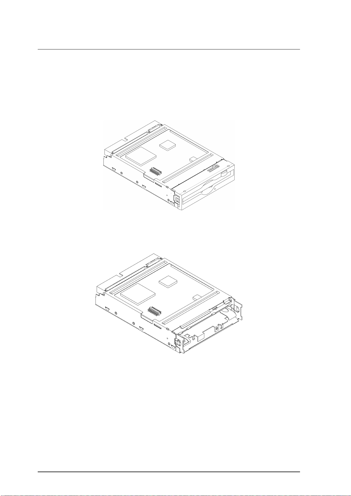
Figures 1.1 and 1.2 show the optical disk drive.
Figure 1.1 The optical disk drive (with panel)
Figure 1.2 The optical disk drive (without panel)
1-6 C156-E228-02EN
Page 27
1.2 Configuration of Optical Disk Drive
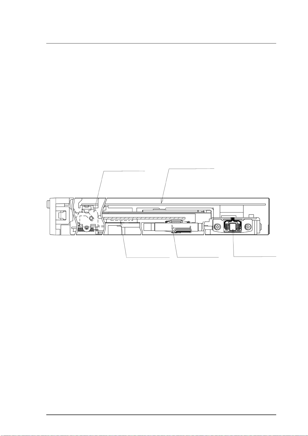
1.2.2 Configuration
Figure 1.3 shows the configuration of the optical disk drive.
The optical disk drive consists of a mechanical section, a fixed optics section, a
control circuit section, and an actuator.
The mechanical section includes the spindle motor, actuator section, bias magnet,
and cartridge holder vertical motion mechanism.
The fixed optics section consists of the optical components, position detector, and
LD controller.
The control circuit section includes the drive control circuit section and I/F circuit
section.
Mechanical section
Spindle motor Actuator
Figure 1.3 Configuration of optical disk drive
1.2.3 Mechanical section
(1) Loading and ejecting an optical disk cartridge
Control circuit section
Fixed optics section
The optical disk drive includes a cartridge load mechanism and an auto eject
mechanism. If an optical disk cartridge is manually inserted in the drive's slot as
far as it will go, the cartridge load mechanism automatically lowers the cartridge
and mounts it on the spindle motor. If the Eject button on the front panel is
pressed, the auto eject mechanism automatically ejects the cartridge.
(2) Spindle motor
An optical disk cartridge hub and the spindle motor shaft are magnetically
combined. Therefore, a disk rotates as fast as the spindle motor shaft rotates. The
spindle motor, a DC brushless motor, provides high-speed rotation at 5,455 rpm
and 3,637 rpm and high-accuracy rotation at ± 0.1%.
C156-E228-02EN 1-7
Page 28

General Description
(3) Actuator section
The actuator section consists of a focus actuator and a tracking actuator. The
former focuses a laser beam on the surface of an optical disk while the latter
moves the beam spot along the radius, on the surface of an optical disk (seek
operation).
The actuator section is directly driven by a linear voice coil motor. The tracking
actuator is based on the pulse-width modulation (PWM) system and realizes low
power consumption and high-speed access.
(4) Separate optical sections
The optical head section has a split structure in which the fixed optics section is
separated from the moving optics section to minimize seek time and positioning
error. This reduces the weight of the moving parts.
The fixed optics section consists of the laser diodes, collimator lens, separation
prism, condensing lens, and the optical detector.
A laser diode for recording and playback transmits one laser beam to the actuator
section.
(5) Panel
The central part of the panel is hollowed out to provide enough space to enable
the cartridge to be inserted by pushing it with a finger, thereby facilitating
insertion.
The panel is also simply designed using an eject button that also serves as LED
light emitting part.
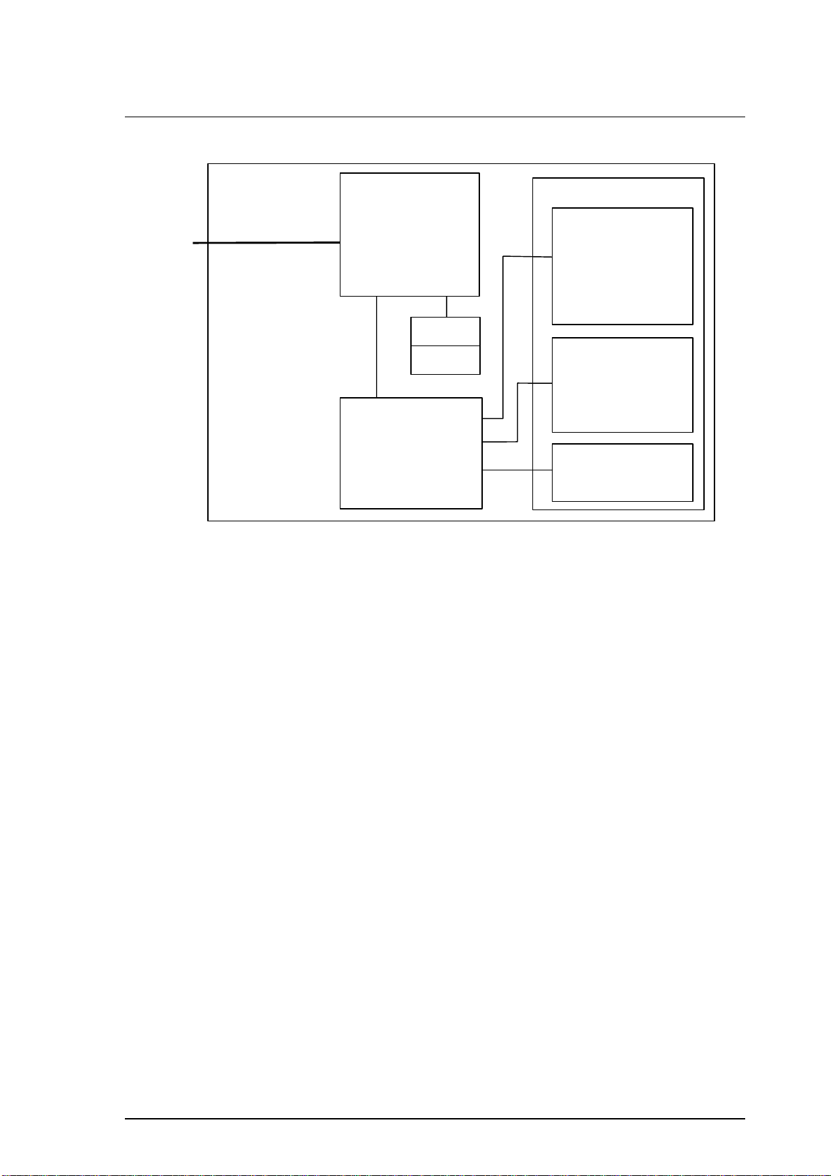
1.2.4 Control circuit section
Figure 1.4 is a block diagram of the control circuit section and the peripheral
sections.
1-8 C156-E228-02EN
Page 29
1.2 Configuration of Optical Disk Drive
B
A
H
SCSI I/F
SCSI controller circuit
section
MPU
ODC
DSP
User Logic
LSI i/f
F-ROM
D-RAM
Driver circuit section
Read Amp
Power Amp
Filter
Sensor
Motor Driver
ead section
Laser Diode
Photo Diode
APC Amp
LPC Amp
Head Amp
ctuator section
Focus Act.
Track Act.
Spindle Motor
Temperature Sensor
ias Coil
Eject Motor
Cartridge Sensor
Mecha section
Figure 1.4 Block diagram of the control circuit section
The control circuit consists of a SCSI controller, which controls operations
between the SCSI interface and the drive interface, and a device circuit section,
which controls the drive circuit.
(1) SCSI controller circuit section
The SCSI controller circuit, which uses an LSI for improved reliability, controls
the drive through SCSI interface control, read-write control, beam control, etc., by
using one high-speed microprocessor (MPU).
(2) Drive circuit section
The drive circuit section consists of the laser diode light emitting control circuit,
signal reproduction circuit, servo/seek control circuit, rotation control circuit, and
other control circuits. In particular, the servo/seek control circuit consists of a
DSP (digital signal processor) for circuit reduction and the realization of a simple
configuration.
The drive circuit section performs the seek, erase, record, and playback operations
while controlling the focus tracking of the beam.
C156-E228-02EN 1-9
Page 30

This page is intentionally left blank.
Page 31

CHAPTER 2 Specifications
2.1 Specifications of Optical Disk Drives
2.2 Specifications of Optical Disk Cartridges
2.3 Defect Management
This chapter provides the specifications of the optical disk drives and the optical
disk cartridge.
2.1 Specifications of Optical Disk Drives
2.1.1 Catalog and order numbers
Table 2.1 lists the model names (catalog numbers) and order numbers of optical
disk drives.
Table 2.1 Representative model names and order numbers
Model name
(catalog number)
MCM3064SS CA06086-B431 With panel Light gray Metric screws (M3)
MCM3130SS CA06123-B431 With panel Light gray Metric screws (M3)
MCP3064SS CA06298-B631 With panel Light gray Metric screws (M3)
MCP3130SS CA06363-B631 With panel Light gray Metric screws (M3)
Order No. Panel Panel color Mounting screws
C156-E228-02EN 2-1
Page 32

Specifications
c
2.1.2 Specifications of drives
Table 2.2 lists the specifications of MCM3064SS, MCM3130SS, MCP3064SS
and MCP3130SS optical disk drives.
Table 2.2 Specifications (1 of 2)
[MCM3064SS, MCM3130SS, MCP3064SS and MCP3130SS]
Item Specifications
Optical disk media 128 MB media 230 MB media 540 MB media 640 MB media 1.3 GB media (*7)
Storage capacity
(one side)
Formatted 128 MB 230 MB 538 MB 643 MB 1.283 GB
Capacity per
track
Formatted 12,800 bytes 12,800 bytes
Capacity per
sector
Formatted 512 bytes 512 bytes 512 bytes 2,048 bytes 2,048 bytes
Number of user tracks/side (*1) 10,000 17,940 42,042 18,480 36,855
Number of alternate sectors/side ≤1,024 ≤1,025 ≤2,250 ≤2,244 ≤4,437
Number of sectors/track 25 25 25 17 17
Data transfer rate 1.65 MB/s
Average seek time (*2) 23 ms (typ)
Average latency
Rotational speed
Heads
Positioner type
Servo tracking method
Recording density
Loading time (*3)
Unloading time (*4)
Load/unload life
Host interface
Data transfer rate (*5)
Unformatted 181 MB 325 MB 819 MB 818 MB 1.688 GB
Unformatted 18,100 bytes 18,100 bytes
Unformatted 725 bytes 725 bytes 778 bytes 2,584 bytes 2,631 bytes
(maximum)
0.39 MB/s
continuous writing
(execution)
1.16 MB/s
ontinuous reading
(execution)
5.5 ms 8.2 ms
5,455 rpm ±0.1% 3,637 rpm ±0.1%
Positioner + Separated optical components
1 (Linear voice coil motor)
ISO continuous servo method
24,424 bpi
(1.04µm/bit)
15,875 TPI
8 sec. (typ) 12 sec. (typ)
4 sec. (typ)
20,000
SCSI-2 (FAST20)
Synchronous mode: 20 MB/s (max.)
Asynchronous mode: 5 MB/s (max.)
(logical track
capacity)
(logical track
capacity)
2.00 to 3.16 MB/s
(maximum)
0.47 to 0.75 MB/s
continuous writing
(execution)
1.40 to 2.23 MB/s
continuous reading
(execution)
29,308 bpi
(0.87µm/bit)
18,275 TPI
19,450 bytes
(logical track
capacity)
12,800 bytes
(logical track
capacity)
3.54 to 5.94 MB/s
(maximum)
0.78 to 1.30 MB/s
continuous writing
(execution)
2.33 to 3.91 MB/s
continuous reading
(execution)
52,900 bpi
(0.48µm/bit)
23,090 TPI
43,928 bytes
(logical track
capacity)
34,816 bytes
(logical track
capacity)
3.52 to 5.87 MB/s
(maximum)
0.93 to 1.55 MB/s
continuous writing
(execution)
2.79 to 4.66 MB/s
continuous
reading
(execution)
45,798 bytes
(logical track
capacity)
34,816 bytes
(logical track
capacity)
3.92 to 6.70 MB/s
(maximum)
0.99 to 1.70 MB/s
continuous writing
(execution)
2.98 to 5.09 MB/s
continuous reading
(execution)
89,100 bpi
(0.285µm/bit)
28,200 TPI
2-2 C156-E228-02EN
Page 33

2.1 Specifications of Optical Disk Drives
Table 2.2 Specifications (2 of 2)
Item Specifications
Optical disk media 128 MB media 230 MB media 540 MB media 640 MB media 1.3 GB media (*7)
Data buffer
Error correction (*6)
2 MB
Correctable up to 8-byte/interleave
Bit error rate: 10
-12
or less
*1 The number of user tracks indicates the maximum user zone which includes
the spare area and slipping area.
*2 Mathematical average of 1,000 times of random seek, which does not
include command overhead or track address recognition time.
Furthermore, it may depend on the quality of the media and the drive
installation environment.
*3 Loading time is the time that elapses from the time an optical disk cartridge
is inserted, to the time the optical disk drive is ready for processing of an
access command.
*4 Unloading time is the time that elapses from the time the eject button is
pressed or the eject command is issued, to the time an optical disk cartridge
is ejected.
*5 The maximum SCSI data transfer rate may be limited by the initiator
response time, SCSI bus transfer characteristics, or transfer distance.
*6 The bit error rate must be 10
10
-4
or less.
-12
or less using a disk whose raw error rate is
*7 The MCM3064SS and MCP3064SS do not support 1.3-gigabyte MO disks.
Power save mode
Power save mode 1 2 3
Time for entering power save
mode (continuous time
without accessing from SCSI)
Power consumption (*8) 3.9 W 2.0 W 1.2 W
Returning time to normal
mode (*8)
2 sec. 5 min 33 min
100 ms 1.0 sec. 5.0 sec.
Power save mode 1: Read Amp., Bias off
Power save mode 2: Servo off, Clock frequency down
Power save mode 3: Spindle off, LD off
*8 Average values in case of environment of a temperature of 25-C, voltage of
5 V and without terminating resistor.
C156-E228-02EN 2-3
Page 34

Specifications
2.1.3 Environmental and power requirements
Table 2.3 lists the environmental and power requirements.
Table 2.3 Environmental and power requirements (1 of 2)
Item Specification
Power
requirements
Power Ready 3.9 W (typ) (*2)
consumption Random seek, read or write 6.1 W (typ) (*2)
(Average) Power save
Outer
dimensions
(W × D × H) Without panel 101.6×148.4×25.4 mm
Weight 410 g (with panel)
Environmental
requirements
Average +5 VDC±5% (*1), 1.2A (2.7A max)
Ripple requirement 100mV pp (DC-1 MHz)
Pre-idle mode
mode
With panel 101.6×150.0×25.4 mm
Operating Temperature: 5 to 45°C (gradient 15°C /h or less)
Idle mode
Standby mode
Sleep mode
3.9 W (typ) (*2)
2.0 W (typ) (*2)
1.2 W (typ) (*2)
1.2 W (typ) (*2)
(*3)
Relative humidity: 10 to 85% (No condensation)
Maximum wet bulb temperature: 29°C or lower
Idle Temperature: 0 to 50°C
Relative humidity: 10 to 85% (No condensation)
Maximum wet bulb temperature: 36°C or lower
Transport Temperature: –40 to 60°C (24 hours or less)
Temperature: –20 to 60°C (24 hours or more)
Relative humidity: 5 to 90% (No condensation)
Maximum wet bulb temperature: 41°C or lower
Installation Tilt angle –5° to +10° (*3)
2-4 C156-E228-02EN
Page 35

2.1 Specifications of Optical Disk Drives
Table 2.3 Environmental and power requirements (2 of 2)
Item Specification
Vibration/
shock
Altitude Operating 3,000 m (10,000 ft) or less
Idle 12,000 m (40,000 ft) or less
Ambient
cleanliness
Air purity General office environment or better
Operating 3.92 m/s2 {0.4 G} (5 to 500 Hz, Sine Sweep)
Shock 19.6 m/s
Idle
No cartridge, power ON
Transport Shock 980 m/s
Air flow Not required
9.8 m/s2 {1.0 G} (5 to 500 Hz, Sine Sweep)
Shock 49 m/s
Requirement: Packing specifications specified by Fujitsu
(dust particle level: Class 5 million o r less particle level)
2
{2 G} (10 ms, Half Sine Pulse)
2
{5 G} (10 ms, Half Sine Pulse)
2
{100 G} (10 ms, Half Sine Pulse)
*1 During random seek or read/write but excluding pulse waveform at 500 µs
or less
*2 Average value at an ambient temperature of 25°C and a voltage of 5 V
*3 The performance is specified at an ambient temperature of 25°C and level
placement at 0°.
Note:
1. The current limiter value on the power supply must not exceed 5 A.
2. The specifications for during transport are under the packaging conditions
specified by Fujitsu.
3. Note that, concerning the power requirements, a voltage drop may occur
depending on the power cable in use.
2.1.4 Error rate
Data blocks to be accessed should be evenly distributed on the disk. Errors due to
disk defects are not included.
(1) Bit error rate after ECC processing
The error rate after ECC processing must be 10
raw error rate is 10
(2) Positioning error rate
The positioning error rate must be 10
-4
or less should be used.
-12
or less. An optical disk whose
-6
or less (with retry).
C156-E228-02EN 2-5
Page 36

Specifications
2.1.5 Reliability
(1) Mean time between failures (MTBF)
The MTBF is 120,000 hours or more. Failures due to disk errors are not included.
Conditions
• Power-on time: 200 hours/month or less
• LD-on time: 20% or less of power-on time
• Ambient temperature: 25°C
Note: The MTBF is defined as follows:
Total operating time in all fields (hours)
MTBF =
Number of device failure in all fields
(2) Service Life
1) Operating time is the total time in which power is supplied.
2) Device failures include failures requiring repair, readjustment, or
replacement. However, they do not include failures that are not due to the
optical disk drive itself but to external factors such as careless device
handling, nonsupport of environmental requirements, power failures, host
system errors, and interface cable errors.
This drive will not require overhaul within the first five years of installation if
properly maintained (both disk media and optical parts cleaned) and handled as
recommended.
Data loss:
Data is not guaranteed if a power failure occurs or the I/F cable is
pulled out while:
• Data is being written to a data block
• A disk is being initialized (formatted)
• Defect processing is in progress
Data is not guaranteed either if the drive is moved with the optical
disk cartridge inserted or the drive is exposed to excessive shock or
vibration.
2-6 C156-E228-02EN
Page 37

2.2 Specifications of Optical Disk Cartridges
2.2 Specifications of Optical Disk Cartridges
2.2.1 Recommended optical disk cartridges
Optical disk cartridges basically comply with the ISO/IEC 10090 standard for 128
MB capacity, ISO/IEC 13963 standard for the 230 MB capacity, and ISO/IEC
15041 standard for the 540 and 640 MB capacity.
Table 2.4 shows the specifications of the optical disk cartridges recommended for
this optical disk drive. The specified drive performance may not be obtained if
other disk cartridges are used.
Table 2.4 Recommended optical disk cartridges
Model Drawing number
Optical disk cartridge (540 MB) with Media ID CA90002-C037
Optical disk cartridge (640 MB) with Media ID CA90002-C016
Optical disk cartridge (1.3 GB) with Media ID CA90002-C017
C156-E228-02EN 2-7
Page 38

Specifications
2.2.2 Appearance
Figure 2.1 shows an optical disk cartridge. The names of the components of an
optical disk cartridge are also shown.
(a) Shutter closed
(2) Shutter
(1) Cartridge case
(b) Shutter open
(3) Write protect tab
Figure 2.1 Optical disk cartridge (1 of 2)
(4) Disk
(5) Hub
Figure 2.1 Optical disk cartridge (2 of 2)
2-8 C156-E228-02EN
Page 39

2.2 Specifications of Optical Disk Cartridges
The following explains the components of the optical disk cartridge shown in
Figure 2.1.
1) Cartridge case
The disk housing is provided to protect the disk from damage when handling
it, and facilitates replacement of the disk.
The cartridge case has a label and a write protect tab on it.
2) Shutter
The shutter protects the disk from contamination. This metallic door opens
when the cartridge is inserted into the optical disk drive.
3) Write protect tab
Slide the write protect tab to enable or disable writing to the disk.
4) Disk
Stores data that can be read or written using a laser beam.
5) Hub
The hub is the central disk part to be connected to the spindle of the optical
disk drive.
The hub is used for radial centering and axial positioning.
C156-E228-02EN 2-9
Page 40

Specifications
2.2.3 Specifications of disk
Table 2.5 lists the disk specifications.
Table 2.5 Disk specifications
Item Specification
Reliability Read cycle >108
Erase/write/read cycle >106
Load/unload cycle 25,000
Archival life (in accordance with
acceleration test results)
Shelf life (in accordance with acceleration
test results)
Environmental
requirements
Operating relative humidity 3 to 85% RH (*3)
Storage temperature –20 to 55°C
Storage humidity 3 to 90% RH (*3)
(1) 128 MB media
Operating temperature 5 to 55°C
*1 Archival life indicates the maximum period during which recorded
information can be read from a disk.
*2 Shelf life indicates the maximum period during which information can be
written to an unrecorded disk.
*3 Maximum wet bulb temperature = 29°C.
Note: Non-recommended disks, if used, must be subject to a compatibility check
by the customer.
>10 years (*1)
>10 years (*2)
The ISO/IEC10090 defines 128-MB media specification.
(2) 230 MB media
The ISO/IEC13963 defines 230-MB media specification.
(3) 540 MB/640 MB media
The ISO/IEC15041 defines 540 MB/640 MB media specification.
(4) 1.3 GB media
The Cherry Book version 1.0 defines 1.3 GB media specification.
2-10 C156-E228-02EN
Page 41

2.3 Defect Management
2.3 Defect Management
2.3.1 Defect management schematic diagram
Defective sectors on the disk must be replaced with good sectors in accordance
with the defect management scheme as follows: Sectors found defective during
surface inspection are handled using a sector slipping algorithm. Sectors found
defective after initialization are replaced using a linear replacement algorithm.
Figure 2.2 shows the sector slipping and linear replacement algorithms.
(a) Sector slipping algorithm (b) Linear replacement algorithm
Figure 2.2 Algorithms for alternate processing
During initialization, the user area is divided into several groups. Each of the
groups contains data sectors and spare sectors. Spare sectors are used as
replacements for defective data sectors. During initialization, the surface
inspection over the user area can be performed.
Figure 2.3 shows an example of alternate processing.
C156-E228-02EN 2-11
Page 42

Specifications
Figure 2.3 Example of alternate processing
2-12 C156-E228-02EN
Page 43

CHAPTER 3 Installation Requirements
3.1 Environmental Requirements
3.2 Mounting Requirements
3.3 Power supply Requirements
3.4 Connection Requirement
This chapter describes environmental, mou nt ing, powe r supply, and connec tion
requirements.
3.1 Environmental Requirements
The optical disk drive must be installed in an environment complying with the
ambient environmental requirements defined in Section 2.1.3.
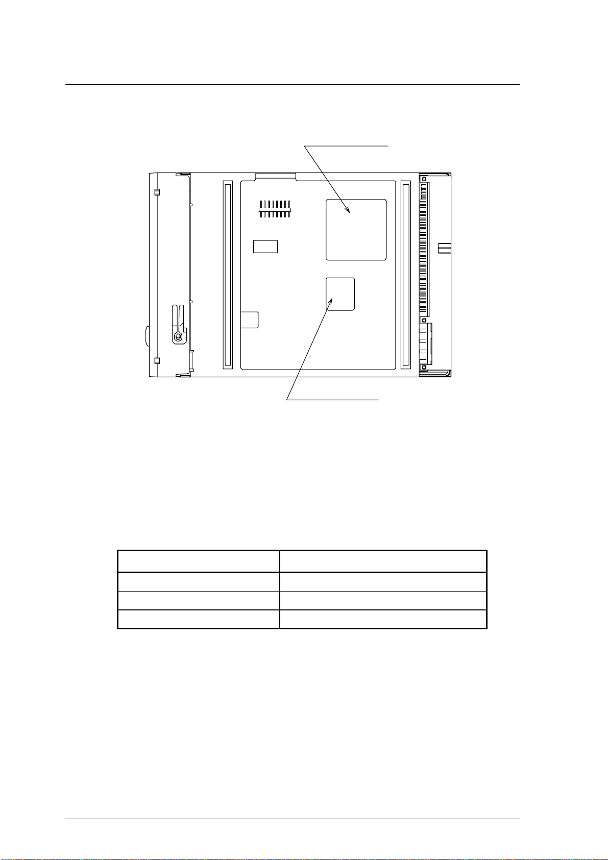
3.1.1 Temperature measurement points
While the drive is operating, the ambient temperatures measured 3 cm away from
the surfaces of the optical disk drive must satisfy the ambient environmental
requirements specified in Section 2.1.3. As for the surface temperatures during
operation, the contact temperatures measured at the points shown in Figure 3.1
must satisfy the temperature requirements specified in Section 3.1.2.
(a) Inside optical disk cartridge
Hole for inserting ther moco uple
Opening of disk outer wall
Tip of thermocouple
Figure 3.1 Surface temperature measurement point (1 of 2)
C156-E228-02EN 3-1
Page 44
Installation Requirements
(b) IC (controller, read Amp)
IC (controller)
Figure 3.1 Surface temperature measurement point (2 of 2)
3.1.2 Temperature requirements
Table 3.1 shows the temperature requirement at the measurement point shown in
Figure 3.1.
Table 3.1 Temperature requirements at measurement points
Measurement point Maximum allowable surface temperature
Inside the cartridge 55°C (*1)
IC (controller) surface 85°C
IC (read Amp.) surface 85°C
*1 60°C for the optical disk cartridges recommended by Fujitsu (except 1.3
GB).
The following describes a procedure for measuring the temperature inside a
cartridge.
IC (read Amp)
1) At the bottom of the cartridge, open a hole large enough for the thermocouple
to be inserted as shown in Figure 3.1.
2) Disassemble the cartridge.
3-2 C156-E228-02EN
Page 45

3.1 Environmental Requirements
3) Cut off part of the wall surrounding the optical disk (disk outer wall) as
shown in Figure 3.1.
At this point, cut off a section 5 to 10 mm in width from the disk outer wall.
4) Using an adhesive agent, affix the tip of the thermocouple to the opening of
the disk outer wall.
5) Pass the thermocouple through the hole in the cartridge and reassemble the
cartridge.
Using an adhesive agent, etc., fill any gap between the hole and the
thermocouple.
Note: The surface of the cartridge shown in Figure 3.1 has been cut away to
illustrate the elements inside the cartridge. Do not actually cut away the
surface.
If the external environ ment tem per atu re ri ses above the specif ied valu e,
the drive will take protective action to deal with the temperature increase
by automatically placing an interval between commands before
responding to a command.
3.1.3 Temperature rise
Table 3.2 Temperatures at measuring points (Reference)
[Ambient temperature of the optical disk drive: 45°C]
Measurement point Random seek Criteria
Inside cartridge 53°C 55°C
IC (controller) surface
IC (read Amp.) surface
Thermal sensor 51°C
Notes:
1. The above data was taken in a constant temperature chamber in which the
temperature around the optical disk drive was kept at 45°C. The data was not
taken with the drive installed in a box in which the drive is actually used.
2. Note that, when installed in a box, the ambient temperature around the drive
will differ depending on the air circulation conditions of the box, and the
temperature increase inside the cartridge will differ accordingly.
73°C 85°C
75°C 85°C
−
C156-E228-02EN 3-3
Page 46

Installation Requirements
3.1.4 Air flow
It is recommended that this optical disk drive be installed in a fanless cabinet.
However, if the power supply is included in the same cabinet, the “Temperature
Conditions” in 3.1.2 must be met. Furthermore, we recommend that the speed of
air drawing in by the device from the left side of the cartridge loading slot in the
front panel dose not exceed 0.3m/s for MCM3064SS or MCM3130SS, and dose
not exceed 0.1m/s for MCP3064SS or MCP3130SS. If this unit is to be used as a
built-in drive, the system fan (if one is supplied) must meet the same conditions.
3.1.5 Air cleanliness
The air cleanliness in the device environment is expressed by the number of dust
particles per unit area. Fujitsu recommends using the optical disk drive in the
environment of class 5 million or less particle level. (Class 5 million: This means
there are 5 million dust particles of 0.5 µm diameter or larger per cubic foot. This
is equivalent to 0.15 mg/m
3.2 Mounting Requirements
3
.)
3.2.1 Outer dimensions
Figures 3.2 to 3.3 show the outer dimensions of the optical disk drive and the
positions of the mounting holes.
3-4 C156-E228-02EN
Page 47

3.2 Mounting Requirements
Figure 3.2 Outer dimensions (1 of 2)
C156-E228-02EN 3-5
Page 48

Installation Requirements
B
Position after a cartridge is loaded
ottom of
the frame
Figure 3.2 Outer dimensions (2 of 2)
Panel
A-A Section
Below 3.3
Position when loading a cartridge
Center of a cartridge when loaded
Below 7.8
Notes
1. Fujitsu recommends using the dimensions indicated by asterisks in the above
figure for the size of the panel opening.
2. If the specified dimensions are not used, the MO disks might be damaged
when a cartridge is loaded.
3-6 C156-E228-02EN
Page 49

3.2 Mounting Requirements
Figure 3.3 Outer dimensions (1 of 3)
C156-E228-02EN 3-7
Page 50

Installation Requirements
Oblong hole: 2±0.1 (width)
× 2.5±0.1 (length)
(Width of C 0.5)
Details on D part
Figure 3.3 Outer dimensions (2 of 3)
Details of C part
(Stroke for the switch)
3-8 C156-E228-02EN
Page 51

3.2 Mounting Requirements
Figure 3.3 Outer dimensions (3 of 3)
C156-E228-02EN 3-9
Page 52

Installation Requirements
M
3.2.2 Installation direction
Figure 3.4 shows the permissible installation directions for the optical disk drive.
The mounting angle tolerance must be within -5° to 10° relative to the horizontal
plane.
(-) shows that the cartridge insertion slot faces downward.
Disk insertion slot
Horizontal
Vertical
(Two orientations)
Eject button/Busy LED
anual eject hole
Figure 3.4 Installation directions
3-10 C156-E228-02EN
Page 53

3.2 Mounting Requirements
3.2.3 Center of gravity
Figure 3.5 shows the center of gravity of the optical disk drive.
Figure 3.5 Center of gravity
C156-E228-02EN 3-11
Page 54

Installation Requirements
o
Mou
m
m
m
m
l
3.2.4 Precautions on mounting
(1) Mounting frame structure and clearance
a) For vibration resistance and heat dissipation, mount this optical disk drive
using a frame having an embossed structure shown in Figure 3.6 or a similar
structure providing an equivalent function.
b) A mounting screw must have an inward projection (entry depth) of 3 mm or
less from the outer surface of the mounting frame of the optical disk drive as
shown in Figure 3.6.
c) The upward-downward and left-right clearance between the external surface
of the mounting frame of the optical disk drive and the user's embossstructure frame must be at least 1.5 mm.
d) The floating clearance of the optical disk drive must be 1.5 mm or more.
e) When mounting the optical disk drive, the screw tightening torque must be
0.4 to 0.45Nm (4 to 4.6kgf-cm).
If the screw tightening torque exceeds the prescribed value, the unit fixture
tap may break, leading to degraded device performance.
f) When the optical disk drive (with a panel) is mounted in a cabinet, there
should be no distortion or deformation in the target housing or the mounting
fittings. Furthermore, the optical disk drive's panel must not be deformed.
If the drive is used with the panel deformed, ejection of the cartridge will
be faulty.
Make sure that the door closes from any position after mounting the optical
disk drive.
1.5 or
ore
1.5 or
ore
3 or less
1.5 or
more
1.5 or
more
1.5 or
more
Optical disk drive
φ15
or less
Mounted on the side
3 or
ess
φ15
r less
1.5 or
ore
1.5 or
ore
Optical disk drive
1.5 or
more
nted on the bottom
Figure 3.6 Mounting frame structure
(Unit: mm)
3-12 C156-E228-02EN
Page 55

3.2 Mounting Requirements
(2) Checking the panel function
There must not be any deformation in the panel after the optical disk drive is
installed in a cabinet. Make sure that the door of the disk insertion slot clos es
from any location with the drive installed in the cabinet.
(3) Service areas
Figure 3.7 shows the locations that need to be accessed for installation, and after
installation is carried out.
Figure 3.7 Service areas
(4) External magnetic fields
Mount the optical disk drive away from powerful magnetic materials (e.g., a
speaker) to avoid any adverse effects from extern al ma gnet ic fields.
(5) Leak magnetic field
The VCM drive magnetic circuit may leak a magnetic field (Up to 2.5 mT at a
distance of 4 mm from the drive surface).
Do not place any devices sensitive to a magnetic field near the
optical disk drive.
(6) External light source
Mount the optical disk drive away from strong light sources (e.g., camera flash).
(7) System ground (handling of SG and FG)
The optical disk drive must be grounded to the signal ground (SG) of the power
supply of the user's system. This SG line must be supplied with the system as well
as the power line.
C156-E228-02EN 3-13
Page 56

Installation Requirements
The optical disk drive can be mounted in a 120 mm (5 inch) device
bay of the PC chassis using either a metal frame or a plastic
(nonconductive material) frame.
If a plastic frame is used, the personal computer's FG and the optical
disk drive's FG are not shorted. Consequently, the static electricity
tolerance is inferior to that rea liz ed when a met al fra m e is used.
Fujitsu recommends using a metal frame. In particular, a metal
frame must be used especially when high static electricity tolerance
is required.
3.3 Power Supply Requirements
(1) Allowable input voltage and current
The DC power supply input voltage must satisfy the requirements described in
Section 2.1.3, "Environmental and power requirements" when measured at the
power supply connector pin (receiving end) of the optical disk drive (For other
requirements, see items (4) and (5) below).
(2) Current waveform (reference)
Figure 3.8 shows the current waveform while a disk is inserted.
Figure 3.8 MCM3130SS current waveform (+5 VDC)
(3) Power on/off sequence
a) In a system which uses the terminating resistor power supply signal
(TERMPWR) of the SCSI bus, the requirements for +5 VDC given in Figure
3.9 must be satisfied between the drive and at least one of the SCSI devices
supplying power to that signal.
3-14 C156-E228-02EN
Page 57

3.3 Power Supply Requirements
Figure 3.9 Power on/off sequence (1)
b) In a system which does not use the terminating resistor power supply signal
(TERMPWR) of the SCSI bus, the requirements for +5 VDC given in Figure
3.10 must be satisfied between the drive and the SCSI device with the
terminating resistor circu it.
4.75V
0.5V
0.5V
4.75V
Figure 3.10 Power on/off sequence (2)
c) Between the drive and other SCSI devices on the SCSI bus, the +5 VDC
power on/off sequence is as follows:
In a system with all its SCSI devices designed to prevent noise leakage to the
SCSI bus when the power is turned on or off, the power sequence does
not matter if the requirement in (a) or (b) is satisfied.
In a system containing an SCSI device which is not designed to prevent noise
leakage to the SCSI bus, the requirement given in Figure 3.11 must be
satisfied between the SCSI device and the drive.
Figure 3.11 Power on/off sequence (3)
C156-E228-02EN 3-15
Page 58

Installation Requirements
(4) Power supply to SCSI terminating resistor
If the power for the terminating resistor is supplied from the drive to other SCSI
devices through the SCSI bus, the current-carrying capacity of the +5 VDC power
supply line to the optical disk drive must be designed with consideration of an
increase of up to 900 mA.
Select a method of power supply to the drive in accordance with the setting
terminal of the optical disk drive. See Subsection 4.3.3.
(5) Noise filter
To eliminate AC line noise, a noise filter should be installed at the AC input
terminal on the power supply unit of the drive. The noise filter specifications are
as follows:
Attenuation: 40 dB or more at 10 MHz
Circuit configuration: The T-configuration shown in Figure 3.12.
Figure 3.12 AC noise filter (recommended)
3-16 C156-E228-02EN
Page 59

3.4 Connection Requirement
3.4 Connection Requirement
3.4.1 Connectors and terminals
This drive is equipped with the connectors and terminals shown below for external
connection. Figure 3.13 shows their locations.
Power supply connector
SCSI connector
External operator panel terminal (CNH2)
Figure 3.13 Connector and terminal locations
C156-E228-02EN 3-17
Page 60

Installation Requirements
(1) Power supply connector
Figure 3.14 shows the shape and pin assignment of the DC power supply input
connector.
1 +12 VDC or N.C.
2 +12 VDC RETURN (GND) or N.C.
3 +5 VDC RETURN (GND)
(2) SCSI connector
The connector for the SCSI bus is an unshielded standard connector with two rows
of 25 pins on 2.54 mm centers.
See Chapter 7 for details on the electrical requirements of the interface signals.
Figure 3.14 Power supply connector
4 +5 VDC
For cables using pin 01 as shield ground, note that the shield of the
connector on the drive is not connected to ground.
3-18 C156-E228-02EN
Page 61

3.4 Connection Requirement
3.4.2 Cable connection requirements
Figure 3.15 shows the cable connection mode between the drive, host system, and
power supply unit. Table 3.3 lists recommended components for the connection.
Figure 3.15 Cable connection mode
C156-E228-02EN 3-19
Page 62

Installation Requirements
Table 3.3 Recommended components for connection
Category Name Model Manufacturer Symbol in
Figure 3.15
SCSI cable
Power supply cable
External operator panel
(1) SCSI cable
A terminating resistor is mounted on the drive when the drive is shipped. A
terminating resistor must be disconne ct ed when the drive is not connect ed to an
end of the SCSI cable. Select a method of power supply to the terminating resistor
circuit according to the setting pins on the drive. See Section 4.2 for details.
Cable socket
(closed-end type)
Cable socket
(through-end type)
Signal cable
Housing for cable
socket
Contact 170121-4 AMP
Cable AWG18 — —
Housing for cable
socket
Receptacle LPC-F104N Honda-Tsushin
Cable AWG28 — —
FCN-707B050-AU/B Fujitsu Ltd.
FCN-707B050-AU/O Fujitsu Ltd.
UL20184LT25PX28AWG
455-248-50 SPECTRA-STRIP
1-480424-0 AMP
LPC-16F02 Honda-Tsushin
Hitachi Cable, Ltd.
S01
—
S2
SH2
(2) Power supply cable
The drive must be star-chain-connected to the DC power supply unit (one-to-one
connection) to reduce the influence of load variations.
3.4.3 External operator panel
Some set switch settings can be manipulated through the external operator panel
interface.
Figure 3.16 shows a recommended circuit for the external operator panel. Since
an external operator panel is not provided as an option, the user must design one
based on the system requirements and the recommended circuit.
3-20 C156-E228-02EN
Page 63

3.4 Connection Requirement
N
N
Provide switches and LEDs (required for the system) on the external
operator panel. See the recommended circuit shown in Figure 3.21.
A signal which is not set on the external operator panel connected to
CNH2 must be set using SW1. The SW1, and CNH1 corresponding
to the signal set on the external operator panel must be set to OFF
position.
For details, see Subsection 4.3.1.
Figure 3.17 shows the external operator panel connector and Table 3.4 shows the
specification of the external operator panel connector interface.
ot assigned
ot assigned
SCSI terminating register mode
*1: This signal indicates that the cartridge is in drive.
H; Exist L: None (TTL level signal)
*2: This signal is used for ejecting the cartridge from the host system
*3: For the LED, the following specification must be satisfied.
Format current: 20 mA or less
Note: The cable length must not exceed 30 cm.
Figure 3.16 External operator panel circuit example
C156-E228-02EN 3-21
Page 64

Installation Requirements
Figure 3.17 External operator panel interface connector
Table 3.4 External operator panel interface
Signal Pin Reference
Function
setting
signal
SCSI-ID 4 2 SW1-01 Equivalent to ON position of SW1-01 by
shorting with 0 V.
SCSI-ID 2 4 SW1-02 Equivalent to ON position of SW1-02 by
shorting with 0 V.
SCSI-ID 1 6 SW1-03 Equivalent to ON position of SW1-03 by
shorting with 0 V.
Device type mode 9 SW1-06 Equivalent to ON position of SW1-06 by
shorting with 0 V. See 3.4.4 (1)
Not assigned 10 – –
Verify mode 11 – See 3.4.4 (3)
Not assigned 13 – –
SCSI type-0 14 – See 3.4.4 (5)
SCSI terminating
resistor mode
15 CNH1(5-6) Equivalent to shorting CNH1 05-06 by shorting
with 0 V.
+LED 3 – LED+terminal for external connection
–LED 5 – LED–terminal for exter nal connec ti on
*EJSW 7 – External eject instruction input (TTL-IC level)
L level: Equivalent to pushing eject switch
H level: Equivalent to not pushing eject switch
CTRGIN 1 – External cartridge sensor output (TTL-IC level)
L level: No cartridge in drive
H level: Cartridge in drive
0 V (GND) 8, 12, 16 – 0 V
3-22 C156-E228-02EN
Page 65

3.4 Connection Requirement
3.4.4 External operator panel settings (CNH2)
(1) Device type mode
Table 3.5 shows the device type settings which are returned when the INQUIRY
command is issued to the optical disk drive.
Table 3.5 Device type mode setting
Device Type CNH 2/Pin 9 - GND
X'07' (Optical memory device) Short
X'00' (Direct access device) Open *
* Setting when shipped
(2) Verify mode
The default setting of the verify function is specified. When the verify mode is
invalid, verification is not performed when the WRITE command is issued. With
the verification invalid, the writing speed is increased by about 20% (depending
on the situation). Table 3.6 shows the verify mode settings. The verification can
also be specified as valid or invalid by the MODE SELECT command.
Table 3.6 Write verify mode setting
Write verify mode CNH 2/Pin 11 - GND
Does not perform verification for the WRITE
command (invalid)
Performs verification for the WRITE command
(valid).
* Setting when shipped
Data loss: When the verify function is invalid, the write data
quality is not guaranteed. This mode should not be used for storing
important data. When using the mode for storing important data, a
preventive system measure such as file duplication is required.
Short
Open*
C156-E228-02EN 3-23
Page 66

Installation Requirements
(3) SCSI type 0
The command specification and message specification are specified. The SCSI-1
specification is compatib le with tha t of the old unit (M2511A). Table 3.7 shows
the command and message specification settings.
Table 3.7 Logical specification type setting
Command specification and message specification CNH 2/Pin 14 - GND
* Setting when shipped
SCSI-2 specification Open*
SCSI-1 specification Short
3-24 C156-E228-02EN
Page 67

CHAPTER 4 Installation
4.1 Notes on Drive Handling
4.2 Connection Modes
4.3 Settings
4.4 Mounting
4.5 Cable Connections
4.6 Operation Confirmation and Preparation for Use after Installation
4.7 Dismounting Drive
This chapter describes notes on handling the drives, co nnection modes, settings,
mounting the drives, cable connections, and operation confirmation and
preparation for use after installation, and notes on demounting the drives.
4.1 Notes on Drive Handling
(1) General notes
Note the following points to maintain drive performance and reliability:
(2) Unpackaging
a) Make sure that the UP label on the package is pointing upward and start
1) Shock or vibration applied to the drive that exceeds the values
defined in the standard damage the drive. Use care when
unpacking.
2) Do not leave the drive in dirty or contaminated environments.
3) Since static discharge may destroy the CMOS devices in the
drive, pay attention to the following points after unpacking:
• Use an antistatic mat and wrist strap when handling the
drive.
• Hold the mounting frame when handling the drive. Do
not touch the PCA except when setting the switches.
4) When handling the drive, hold both sides of the mounting
frame. When touching other than both sides of the mounting
frame, avoid putting force.
5) Do not forcibly push up the end of the header pin of the printed
circuit board unit when handling or setting the drive.
unpacking on a level surface. Handle the drive on a soft surface such as a
rubber mat, not on a hard surface such as a desk.
C156-E228-02EN 4-1
Page 68

Installation
(3) Installation
b) Use care to avoid exerting excessive pressure on the unit when removing the
cushions.
c) Use care to avoid exerting excessive pressure on the PCA surface and
interface connectors when removing the drive from the antistatic bag.
d) If the temperature difference betwe en ins talla tion locations is 10 degrees or
more, leave the drive in the new location for at least two hours before
unpackaging it.
a) Do not connect or disconnect the connectors or change the terminal settings
when the power is on.
b) Do not move the drive with the power on.
c) Eject the optical disk cartridge, lock the carriage securing the head, turn off
the power, then move the drive.
Before moving the drive, remove the optical disk cartridge. If the
drive is moved with the optical disk cartridge loaded in it, the head
may move back and forth in the drive to damage the head or disk
and reading the data may fail.
(4) Packaging
a) Before packaging, remove the optical cartridge.
b) Store the drive in an antistatic plastic bag with desiccant (silica gel).
c) Use the same cushions and packaging supplied with the drive. If they are not
available, ensure that adequate shock abso rben t ma ter ia l is used. In this case,
some method of protecting the PCA surface and interface connectors must be
used.
d) Ap "UP" and "Handle With Care" labels to the outside of the package.
Figure 4.1 shows the individual packaging style and Figure 4.2 shows the gathered
packaging style. (The form and material of the cushion may be changed. )
4-2 C156-E228-02EN
Page 69

4.1 Notes on Drive Handling
Holder
Label
Drive
Desiccant
Ejecting Jig
Packing box for
each individual unit
Ejecting Jig
Desiccant
Drive
Holder
Carton of
Box
Label
packing boxes
Figure 4.1 Individual packaging style Figure 4.2 Gathered packaging style
(5) Transportation
a) Transport the package with the UP sign upward.
b) After unpacking, minimize the transportation distance and use cushions to
avoid shock and vibration. Transport the drive in one of the orientations
described in Subsection 3.2.2 after unpacking. (The horizontal direction is
recommended.)
(6) Storage
a) Use moistureproof packaging when storing the drive.
b) The storage environment must satisfy the requirements specified in
Subsection 2.1.3 when the drive is not operating.
c) To prevent condensation, avoid sharp changes in temperature.
C156-E228-02EN 4-3
Page 70

Installation
4.2 Connection Modes
Figure 4.3 shows examples of connections between the host system and the optical
disk drive. Up to eight devices including the host adapter, optical disk drive, and
other SCSI equipment can be connected to the SCSI bus in arbitrary combinations.
Install a terminating resistor on the SCSI devices connected to either end of the
SCSI cable.
See Section 3.4 for the cable connection requirements and power cable
connections.
(a) Connecting one optical disk drive
(b) Connecting more than one optical disk drive (single host)
Figure 4.3 SCSI bus connection modes (1 of 2)
4-4 C156-E228-02EN
Page 71

4.3 Settings
(c) Connecting more than one optical disk drive (multi-host)
4.3 Settings
Before installing the drive in the syste m, set the fol low ing set ting term ina l, setting
switches, and SCSI terminating resistors:
• Setting terminal : CNH1
• Setting switches : SW1
Figure 4.4 shows the positions of the setting terminal and switch.
Figure 4.3 SCSI bus connection modes (2 of 2)
1) The user must not change the settings of terminals not described
in this section. The terminals must remain as set when shipped.
2) Do not change terminal settings when the power is on.
3) To strap setting terminals, use the jumper shipped with the
drive.
C156-E228-02EN 4-5
Page 72

Installation
Figure 4.4 Positions of setting terminals and switches
Setting items are as follows:
• SW1
SCSI ID
SCSI data bus parity check
Write cache mode
Device type mode
Spindle automatic stop mode
Factory test mode (user setting inhibited)
• CNH1
SCSI terminating resistor power supply
SCSI terminating resistor mode
• CNH2
SCSI ID
Device type mode
Verify mode
SCSI type-0
• SCSI connector
SCSI signal
• Power connector
+5VDC
GND
4-6 C156-E228-02EN
Page 73

4.3 Settings
4.3.1 Setting switches (SW1)
Figure 4.5 shows the types of switches and their settings when the drive was
shipped.
• SW1
SCSI ID OFF
SCSI ID
SCSI ID
Setting
switch
Board
1
2
3
4
5
6
7
8
Switch number Signal name At shipment
SW1 01
02
03
SCSI ID OFF
OFF
OFF
04 SCSI data bus parity check ON
05 Write cache mode OFF
06 Device type mode ON
07 Spindle automatic stop mode ON
08 Factory test mode (user setting inhibited) OFF
Figure 4.5 Setting switch (SW1)
C156-E228-02EN 4-7
Page 74

Installation
(1) SCSI ID
Table 4.1 shows the SCSI ID settings of the drive.
Table 4.1 SCSI ID setting (SW1)
SCSI ID SW1-01 SW1-02 SW1-03
0 (*1) OFF OFF OFF
1 OFF OFF ON
2 OFF ON OFF
3 OFF ON ON
4 ON OFF OFF
5 ON OFF ON
6 ON ON OFF
7 ON ON ON
*1 Setting when shipped
1) Each SCSI device connected to the same SCSI bus must have a
unique SCSI ID.
2) If contention occurs in the ARBITRATION phase, the priority
of the SCSI use authority depends on SCSI IDs as follows:
7 > 6 > 5 > 4 > 3 > 2 > 1 > 0
(2) SCSI data bus parity checking
Table 4.2 shows the settings which determine whether to check the SCSI bus
parity bit. Regardless of the settings, the parity bit is ensured for data transmitted
by the drive.
Table 4.2 SCSI data bus parity checking (SW1)
SCSI data bus parity checking by drive SW1-04
Checked ON (*1)
Not checked OFF
*1 Setting when shipped
4-8 C156-E228-02EN
Page 75

4.3 Settings
(3) Write cache mode
The write cache mode can be set. The write cache mode can also be enabled or
disabled by the MODE SELECT command.
When the write cache mode is enabled, the cache control page is added to the code
page of the mode parameter even if the SCSI-1 is set. Table 4.3 shows the settings
of the write cache mode.
Table 4.3 Write cache mode setting
Write cache mode SW1-05
Write cache is enabled at executing the
WRITE/WRITE AND VERIFY command.
Write cache is disabled at executing the
WRITE/WRITE AND VERIFY command
*1 Setting when shipped
(4) Device type mode
The device type settings, which are returned when the INQUIRY command is
issued to the optical disk drive, are shown below.
X‘00’ (Direct access device) OFF
ON
OFF (*1)
When the write cache feature is enabled, a write error is reported at
the completion status of next command. At a system so that the
initiator retries the command, a retry process may be failed.
Table 4.4 Device type mode settings
Device type Setting terminal (SW1-06)
X‘07’ (Optical memory device) ON (*1)
*1 Setting when shipped
(5) Spindle automatic stop mode
Normally, with the cartridge loaded, the spindle rotation is maintained until the
spindle is instructed to stop by the START/STOP UNIT command. The spindle
auto stop function automatically stops the spindle after the command has not been
issued from the host for about 33 minutes (default value). When the co mmand is
issued from the host with the spindle automatically stopped, the optical disk derive
turns the spindle again and performs processing in the same manner as in a ready
state without posting a not ready state.
C156-E228-02EN 4-9
Page 76

Installation
The access supervision time from the host is about 33 minutes as the default.
However, it can be changed by the MODE SELECT command.
The spindle auto stop mode can also be changed by the MODE SELECT
command.
Table 4.5 shows spindle auto stop mode setting.
Table 4.5 Spindle automatic stop mode setting
Spindle auto stop SW1-07
The spindle motor automatically stops. ON (*1)
The spindle motor does not automatically stop. OFF
*1 Setting when shipped
The characteristic of the spindle auto stop function are as follows:
• Reduces the deposition of dust which could cause a cartridge error.
• Not suitable for a system requiring quick response because it takes a
few seconds to start the spindle.
4.3.2 Setting of supplying power to SCSI terminating resistor
Table 4.6 shows how to supply power to the SCSI terminating resistor module on
the drive and how to use TERMPWR lines on the SCSI bus.
Table 4.6 SCSI terminating resistor power supply (CNH1)
SCSI terminating resistor power supply CNH1 01-02 CNH1 03-04
Power is supplied from both of the drive and
TERMPWR pin.
Power is supplied from the drive only.
(TERMPWR pin is not used)
Power is supplied from TEMPWR pin only.
(Drive’s power supply is not used)
No power is supplied. Open Open
Short (*1) Short (*1)
Short Open
Open Short
*1 Setting when shipped
4-10 C156-E228-02EN
Page 77

4.3 Settings
4.3.3 SCSI terminating resistor mode
Enabling or disabling the SCSI terminating resistor, module on the PCA can be
set.
When the drive positions at other than the end of the SCSI bus, the SCSI
terminating resistor should be disabled. Table 4.7 shows the SCSI terminating
resistor mode setting.
Table 4.7 SCSI terminating resistor mode (CNH1)
SCSI terminating resistor mode CNH 1 05-06
SCSI terminating resistor module on the PCA is enabled. Short (*1)
SCSI terminating resistor module on the PCA is disabled. Open
*1 Setting when shipped
Note:
Open CNH1 5-6 pins when the SCSI terminating resistor set by CHN 2-15 pin.
C156-E228-02EN 4-11
Page 78

Installation
4.4 Mounting
4.4.1 Checks before mounting the drive
Before mounting the optical disk drive in the system cabinet, check whether the
setting switches and terminals are set correctly.
Table 4.8 shows the checklist.
Table 4.8 Setting checklist
Setting item Setting on: Default
1 SCSI ID
SW1-01
SW1-02
SW1-03
2 SCSI data bus parity check SW1-04 ON o OFF o ON
3 Write cache mode SW1-05 OFF o OFF o ON
Setting switch
4 Device type mode SW1-06 ON o OFF o ON
5 Spindle automatic stop mode SW1-07 ON o OFF o ON
6 Factory test mode
(user setting inhibited)
Setting item Setting on: Default
1 Supplied from both ODD and
TERMPWR pin.
2 Supplied from ODD CNH1 1-2
CNH1
SW1-08 OFF o OFF o ON
CNH1 1-2
CNH1 3-4
CNH1 3-4
OFF
OFF
OFF
Short
Short
Short
Short
Check
(SCSI ID= )
o OFF o ON
o OFF o ON
o OFF o ON
Check
o Short o Open
o Short o Open
o Short o Open
o Short o Open
3 Supplied from TERMPWR pin. CNH1 1-2
CNH1 3-4
Check item Check
1 Drive location on SCSI bus o Other o Either
resistor
2 SCSI terminating resistor mode (CNH1 5-6)
Terminating
4-12 C156-E228-02EN
Short
Short
than end end
o Open o Short
o Short o Open
o Short o Open
Page 79

4.5 Cable Connections
4.4.2 Mounting procedure
How the drive is mounted depends on the system cabinet structure. Determine the
mounting procedure in consideration of the requirements of each system. This
section contains the general mounting procedure and check items.
See Section 3.2 for details on mounting drive.
1) For a system with an external operator panel mounted, connect the external
operator panel cable before mounting the drive in the system cabinet because
it is difficult to access the connector after the drive is mounted.
2) Tighten four mounting screws to secure the drive in the system cabinet.
The drive has ten mounting holes (both sides: 3×2, bottom: 4). Secure the
drive using the four mounting holes on both sides or the bottom.
Use mounting screws whose lengths are 3 mm or less from the external wall
of the mounting frame of the drive when they are tightened. (See Figure
3.6)
When mounting with screws, the screw tightening torque should be 0.4 to
0.45Nm (4 to 4.6kgf-cm).
Be careful not to damage the parts on the PCA when mounting the drive.
3) After securing the drive, make sure that the drive does not touch the chassis of
the system cabinet. There must be at least 1.5 mm clearance between the
drive and chassis. (See Figure 3.6)
4.5 Cable Connections
Use the following cables to connect the drive to the system. See Subsection 3.4.2
for details on the connector positions and cable requirements.
• Power supply cable
• SCSI cable
• External operator panel cable (if required)
The general procedure for cable connection and notes on connecting cables are
given below. Pay attention to the insertion direction of each cable connector.
1) Make sure that the system power is off.
2) Do not connect or disconnect any cable when the power is on.
1) Connect the power cable.
2) Connect the external operator panel (only if required for the system).
3) Connect the SCSI cable.
C156-E228-02EN 4-13
Page 80

Installation
4) After each cable connector is connected, secure the cable so that the cable
does not touch the drive or the parts on the PCA or obstruct the flow of
cooling air in the system cabinet.
1) Be careful of the insertion directions of SCSI connectors. For a
system in which the terminating resistor power is supplied via
the SCSI cable, connecting connectors in the wrong direction
may cause the following:
The overcurrent protection fuse of the term ina ting resi stor
power supply (SCSI device) may blow when power is turned
on.
The cable may burn if overcurrent protection is not provided.
2) Be careful of cable connector positions when connecting more
than one SCSI device. The SCSI device having the terminating
resistor must be connected to the end of the cable.
3) The cables must be kept away from the rotating part of the
spindle motor.
4.6 Operation Confirmation and Preparation for Use after Installation
4.6.1 Confirming initial operations
This section provides the operation check procedures after the power is turned on.
(1) Initial operation when the power is turned on
• When the power is turned on, the drive starts initial self-diagnosis. The LED
on the front panel is on for 1 second during initial self-diagnosis.
• If an error is detected during initial self-diagnosis, the LED on the front panel
blinks.
• In case of not inserted the cartridge, when the power is turned on, the eject
motor automatically turns once.
(2) Checks if errors occur at initial self-diagnosis
• Make sure that the cables are connected correctly .
• Make sure that the supply voltage is correct. (Measure the volt age at the
power supply connector of the optical drive.)
• Make sure that the settings of all terminals are correc t.
• If the LED on the front panel blinks continuously, an error was detected
during initial self-diagnosis. In this case, issue the REQUEST SENSE
command from the initiator (host sy ste m) to obtain sen se da ta for error
analysis.
4-14 C156-E228-02EN
Page 81

4.6 Operation Confirmation and Preparation for Use after Installation
The BUSY LED is on while the optical disk drive is executing seek,
write, or read operations. The BUSY LED is on momentarily, so it
seems as if it blinked or is off.
The eject motor turns once when the power is turned on so that in
case the spindle motor position deviates due to shocks received by
the drive during transport the position is corrected to allow the
cartridge to be inserted normally. If the cartridge fails to be inserted,
remove the cartridge and turn on the drive power to turn the eject
motor once and reinsert the cartridge.
4.6.2 SCSI connection check
When initial operation checks out normally after the power is turned on, check
whether the drive is correctly connected to the SCSI bus from the host system.
Checking the SCSI connection depends on the host system configuration. This
section describes the general procedure.
(1) Procedure
Figure 4.6 shows the recommended checking procedure.
Note:
Steps a) to c) correspond to a) to c) in Figure 4.6.
a) Issue the TEST UNIT READY command and check that the drive is
connected correctly to the SCSI bus.
b) Use the WRITE BUFFER and READ BUFFER commands to check whether
the SCSI bus operates normally. Use data whose bits change to 0 or 1 at least
once. (Example: A X'00' to X'FF'increment pattern)
c) Check whether the settings are correct. Also, make sure that the controller
and drive operate normally.
C156-E228-02EN 4-15
Page 82

Installation
Figure 4.6 SCSI connection check
4-16 C156-E228-02EN
Page 83

4.7 Dismounting Drive
(2) If processing terminates abnormally:
a) If sense data has been obtained by the REQUEST SENSE command, analyze
the sense data. If the error is recoverable, retry the processing.
b) Check the following items for SCSI cable connection:
All connectors, including other SCSI devices, are connected correctly.
A terminating resistor is correctly mounted at both ends of the cable.
Power is supplied to the terminating resistors correctly.
c) Check the settings of all terminals are correct. Note that the procedure of
checking the SCSI connection depends on the setting of "spindle automatic
stop".
4.7 Dismounting Drive
How to demount an optical disk drive (for setting terminal checking, setting
change, or device replacement) depends on the system cabinet configuration.
Determine the demounting procedure in consideration of the requirements of each
system. This section describes the general demounting procedure and notes on
demounting drives.
Before demounting the optical disk drive, turn off the system power.
Do not remove screws securing the cables and drive when the power
is on.
1) Remove the power cable.
2) Remove the SCSI cable.
3) When an external operator panel is mounted, remove its cable. If it is difficult
to access the connector, remove the cable after step e).
4) Remove the DC ground cable.
5) Remove the four screws securing the drive, then remove the drive from the
system cabinet.
6) When storing or transporting the drive, put the drive into an antistatic bag.
(See Section 4.1.)
C156-E228-02EN 4-17
Page 84

This page is intentionally left blank.
Page 85

CHAPTER 5 Operation and Cleaning
5.1 Operation of Optical Disk Drive
5.2 Cleaning of Optical Disk Drive
5.3 Operation of Optical Disk Cartridge
5.4 Cleaning of Optical Disk Cartridge
This chapter describes how to operate and clean the optical disk drive and an
optical disk cartridge.
5.1 Operation of Optical Disk Drive
The optical disk drive has automatic load and eject functions. All of the operator
must do about the drive is to insert an optical disk cartridge and push the eject
button. This section explains loading and ejecting an optical disk cartridge,
assuming that the drive is mounted horizontally. You can operate the drive in the
same manner even when it is mounted vertically.
Figure 5.1 shows the front view of the optical disk drive. The following sections
explain the names and functions of parts that a user should know for operation as
well as methods of loading and ejecting an optical disk cartridge.
5.1.1 Appearance of optical disk drive
3) Manual eject hole
Figure 5.1 Optical disk drive front view (with panel)
The following explains the parts and functions of the optical disk drive (the
following numbers correspond to those in Figures 5.1):
2) Eject button/BUSY LED
C156-E228-02EN 5-1
Page 86

Operation and Cleaning
1) Disk insertion slot
Insert and eject an optical disk cartridge into and out of this slot.
2) Eject button & BUSY LED (indicator lamp)
On this optical disk drive, the eject button serves also as the BUSY LED
(indicator lamp). Eject an optical disk cartridge by pressing this button,
which also goes on in green during seeking and during erasing, writing or
reading of data. When ejection is disabled by an SCSI command, an optical
disk cartridge cannot be taken out.
3) Manual eject hole
Use this hole to eject an optical disk cartridge manually at power-off.
5.1.2 Precautions
To maintain the performance and reliability of the drive and to prevent data from
being damaged, observe the following instructions:
• Do not eject an optical disk cartridge while the drive is in the Busy state.
Particularly, do not manually eject the cartridge by force.
• Be extra careful not to insert the wrong media such as a floppy disk or foreign
matter, which causes a malfunction of the drive.
5.1.3 Inserting an optical disk cartridge
Insert an optical disk cartridge as follows (s ee Figur e 5.2):
(1) While the drive is powered on:
1) Make sure that there is no other optical disk cartridge in the drive.
2) Hold an optical disk cartridge with the printed shutter surface facing upward.
3) Press the opening section of the cartridge against the disk insertion slot.
4) Hold the center of the rear half of the cartridge to insert the cartridge straight
into the slot until the cartridge is lowered to the bottom (a little inside the
operator panel).
The cartridge starts to be loaded when it has been inserted. The BUSY LED
indicator lamp goes on immediately and goes off in a few seconds, indicating the
completion of loading.
Notes:
1. Insert a cartridge as far as it will go until the BUSY LED indicator lamp goes
on.
2. A cartridge may not be sufficiently inserted if you press only the left or right
edge of the rear half of the cartridge. Be sure to push the central part straight
into the slot as far as it will go.
5-2 C156-E228-02EN
Page 87

5.1 Operation of Optical Disk Drive
3. If the BUSY LED indicator lamp does not go on after a cartridge is inserted,
press the eject/BUSY LED button once to eject the cartridge and insert it
again.
4. Do not forcibly insert a cartridge if you have any difficulty inserting it. If you
do, the drive may be damaged. In such a case, be sure to remove the cartridge
once and check the insertion orientation and the face and back of the cartridge
before inserting it again.
(2) While the drive is powered off:
1) Make sure that there is no other optical disk cartridge in the drive.
2) Hold an optical disk cartridge with the printed shutter surface facing upward.
3) Press the opening section of the cartridge against the disk insertion slot.
4) Hold the center of the rear half of the cartridge to insert the cartridge straight
into the slot until the cartridge is lowered to the bottom (a little inside the
operator panel).
The cartridge remains where it has been inserted. If you power on the drive, the
BUSY LED indicator lamp goes on.
Notes:
1. If the BUSY LED indicator lamp does not go on when the power is turned on,
press the eject button to eject the cartridge and then insert it again until the
lamp goes on.
2. A cartridge may not be sufficiently inserted if you press only the left or right
edge of the rear half of the cartridge. Be sure to push the central part straight
into the slot as far as it will go.
3. Do not forcibly insert a cartridge if you have any difficulty inserting it. If you
do, the drive may be damaged. In such a case, be sure to remove the cartridge
once and check the insertion orientation and the face and back of the cartridge
before inserting it again.
Push on the back of the cartridge somewhere within the area extending 20 mm
from left of center to 20mm from right of center, up to the location shown on
the right.
Figure 5.2 Inserting an optical disk cartridge
C156-E228-02EN 5-3
Page 88

Operation and Cleaning
If you insert an optical disk cartridge with the printed shutter facing
upward by pressing on the rear of cartridge at the left edge, you may
hear an audible click but the drive may not become READY. In
such a case, press the cartridge further by pressing on the back of the
cartridge from the center (somewhe re nea r the notched section of th e
panel front) until the LED indication lamp goes on. If this happens,
the cartridge has been normally inserted.
5.1.4 Removing an optical disk cartridge
Remove an optical disk cartridge as described below.
(1) While the drive is powered on:
1) Press the eject switch to remove an optical disk cartridge (see Figure 5.3).
Notes:
1. No optical disk cartridge can be removed if the SCSI command inhibits
ejection.
2. Remove an optical disk cartridge after it is completely ejected.
3. Be careful not to let a cartridge drop out of the drive when it is ejected. This
may happen depending on the ambient environment and the cartridge's
condition even if the drive installation conditions are met.
(2) While the drive is powered off:
While the drive is powered off, you cannot remove an optical disk cartridge by
pressing the eject switch.
To remove a cartridge in such a case, insert an accessory eject jig or a pin about 1
mm in diameter into the manual eject hole (see Figure 5.1) and push on it.
Notes:
1. NEVER eject a cartridge while the BUSY LED lamp is on. The data may be
destroyed or the drive may be damaged.
2. Note that a cartridge may drop out of the drive when it is ejected.
3. Do not carry the optical disk drive around while a cartridge is loaded in it.
5-4 C156-E228-02EN
Page 89

5.2 Cleaning of Optical Disk Drive
Figure 5.3 Removing an optical disk cartridge
5.2 Cleaning of Optical Disk Drive
The drive performance may deteriorate if dust, particle or cigarette smoke deposits
accumulate on the lens actuator of the drive. Clean the lens actuator periodically
using following head cleaner (*1).
*1 How often the lens actuator should be cleaned varies depending on the
environment in which the optical disk drive has been installed. Usually, clean
the lens actuator once every three months.
Table 5.1 Head cleaner
Product name Product number Order number
Head cleaner 0240470 CA90002-C980
Clean the lens actuator using the head cleane r as follo w s:
1) Power on the optical disk drive.
2) Insert the head cleaner.
3) When the head cleaner is automatically loaded, the optical head positioner
moves back and forth to cause the head cleaner's cleaning brush to clean the
object lens.
4) When the cleaning is finished, the head cleaner is automatically ejected.
Note: The cleaning time is around 15 seconds.
C156-E228-02EN 5-5
Page 90

Operation and Cleaning
Device Damage:
Be sure to use the dedicated head cleaner shown above.
Check the state of the cleaning brush by opening the shutter of the
head cleaner. If the tips of the brush bristles are spread out, the lens
cannot be completely cleaned. In such a case, use a new head
cleaner.
5.3 Operation of Optical Disk Cartridge
5.3.1 Appearance
Figure 5.4 shows the appearance of an optical disk cartridge. It also shows the
names of components of an optical disk cartridge that you should be familiar with
for operation and cleaning.
See Section 2.3.2, "Appearance" for the functions of these components.
5-6 C156-E228-02EN
Page 91

5.3 Operation of Optical Disk Cartridge
(
(4) D
(a) Shutter closed
(2) Shutter
(1) Cartridge case
(3) Write protect tab
(b) Shutter open
isk
5) Hub
Figure 5.4 Appearance of optical disk cartridge
C156-E228-02EN 5-7
Page 92

Operation and Cleaning
5.3.2 Write protect tab
Move the write protect tab to enable or disable writing to an optical disk cartridge.
Use a fingernail or something similar to move the write protect tab (it must be
completely moved to one end because there is some play in the middle).
Figure 5.5 shows where the write protect tab is located on a optical disk cartrid ge
and how the write protect tab should be moved (see the Write Enabled and Write
Disabled indications printed on the label).
Write protect tab
Tab moved
to this end
Write enabled
Write disabled
Note: The write protect tab should be at each of the shaded portions.
Figure 5.5 Write protect tab
Tab moved
to this end
5-8 C156-E228-02EN
Page 93

5.3 Operation of Optical Disk Cartridge
5.3.3 Precautions
To maintain the performance and reliability of an optical disk cartridge, keep the
following points in mind when using, storing, or transporting an optical disk
cartridge:
(1) Using a cartridge
• Do not use a cartridge in an environment where it is exposed to direct sunlight
or sharp temperature changes, or high temperature or humidity.
• Do not press hard, drop, or otherwise apply excessive shock or vibration to a
cartridge case or shutter.
• Do not use a cartridge in an environment filled with dust, particle, or cigarette
smoke.
• Do not open the shutter or touch the surface of a disk with bare fingers.
(2) Storing a cartridge
• Do not place a heavy object on a cartridge.
• Do not store a cartridge in an environment where it is exposed to direct
sunlight or sharp temperature changes, or high temperature or humidity.
• Do not store a cartridge in an environment filled with dust, particle, or
cigarette smoke.
(3) Transporting a cartridge
• Transport a cartridge sealed in a nylon bag or the equivalent, to protect it from
moisture during transportation.
• Put a cartridge in a solid container and cover the cartridge with appropriate
cushioning materials to protect it from damage during transportation.
C156-E228-02EN 5-9
Page 94

Operation and Cleaning
5.4 Cleaning the Optical Disk Cartridge
You must periodically clean an optical disk cartridge because the accumulation of
dust, particle, or cigarette smoke deposi ts on the disk lowers the per forman ce o f
the cartridge. How often the cartridge should be cleaned varies depending on the
environment in which the optical disk drive has been installed. Usually, clean the
cartridge once every 300 hours of operation or once in two to three months.
5.4.1 Cleaning tool for optical disk cartridge
Use the following cleaning kit to clean an optical disk cartridge.
(1) Cleaning kit
This cleaning kit is for a 3.5-inch optical disk cartridge only. Read the attached
instruction manual and use the cleaning kit correctly. Table 5.2 shows the
specifications of the cleaning kit.
Table 5.2 Cleaning kit
Product name Product number Order number
Cleaning kit 0632440 CA90003-0702
Table 5.3 shows the packing list of the cleaning kit.
Table 5.3 Packing list for cleaning kit
Name Quantity
Setting case 1
Cleaning cloth
Cleaning solution 1 bottle (20ml)
The following refill kit is available for the cleaning solution and cloth.
• Product number 0632450
• Order number CA90002-D901
5 pieces (70mm × 70mm)
Disk damage: To clean a disk, use the cleaning solution and
cleaning cloth specified in Table 5.2.
If a cleaning solution or cleaning cloth other than the one specified is used, the
surface of a disk may be damaged.
5-10 C156-E228-02EN
Page 95

5.4 Cleaning the Optical Disk Cartridge
(2) Precautions on use and storage of cleaning kit
Keep the following in mind when using or storing the cleaning kit:
• Tighten the cap after using the cleaning solution.
• Do not insert a floppy disk or stack floppy disks in the setting case because a
magnet is used at the disk revolving knob of the setting case.
• Do not use or store the cleaning kit in an environment where it is exposed to
direct sunlight or near a flame.
• Keep the cleaning kit out of the reach of children.
Disk damage: Do not use this cleaning kit on a floppy disk or an
optical disk cartridge to be used on other optical disk drives.
5.4.2 Cleaning of optical disk cartridge
Clean an optical disk cartridge as follows:
Disk damage: Clean a cartridge in a dust-free environment.
Fujitsu recommends wearing disposable gloves during cleaning so
that no fingerprints are left on a disk.
1) Slide the cartridge shutter until it is completely open (see Figure 5.6).
Figure 5.6 Opening a shutter
2) Set the cartridge with the printed shutter surface facing downward and with
the shutter completely open, into the shutter stopper of the setting case as
shown in Figure 5.7.
C156-E228-02EN 5-11
Page 96

Operation and Cleaning
O
O
Cartridge
Shutter
Spindle
Setting case lid
Setting case
Optical disk
Shutter stopper
Figure 5.7 Setting an optical disk cartridge into the setting case
Disk damage: Do not press hard or apply excessive shock to an
optical disk cartridge case while setting it in the setting case.
3) Place the setting case cover over the cartridge while inserting the disk
revolving knob pin into the center hub of the cartridge (see Figure 5.8).
Disk revolving knob
Setting case cover
4) When wiping the disk, remove from the disk surface any fragments that may
5) Moisten the accessory cleaning cloth with a few drops of the cleaning
Figure 5.8 Placing the setting case cover
damage it.
solution.
ptical disk
Cartridge opening
ptical disk hub
5-12 C156-E228-02EN
Page 97

5.4 Cleaning the Optical Disk Cartridge
Eye inflammation: If the cleaning solution gets into your eyes,
immediately wash the solution away with water.
6) Gently wipe the disk surface, going from the center to the edge of the disk.
7) After wiping, turn the disk-revolving knob and then wipe the next section in
the same manner (see Figure 5.9).
Cleaning cloth
Figure 5.9 Cleaning of disk surface
8) Wipe off any excess cleaning solution remaining on the disk surface, using a
new portion of the cleaning cloth (where no cleaning solution is abso rbed ).
C156-E228-02EN 5-13
Page 98

This page is intentionally left blank.
Page 99

CHAPTER 6 Diagnostics and Maintenance
6.1 Diagnostics
6.2 Maintenance Information
This chapter provides diagnostics and maintenance information.
6.1 Diagnostics
Table 6.1 lists test items during diagnostics.
The optical disk drive has a self-diagnostics function. This function can check the
normality of basic operations of the drive.
To check the generation operations including the operations of the interface with
the host system, provide a test program that can run in the host system (see Section
6.1.3).
Table 6.1 Diagnostics function
Description of diagnostics Diagnostics item
Initial self-diagnostics Basic operations
Diagnostic command Basic operations
Test program General operations
6.1.1 Initial self-diagnostics
When the power is turned on, the optical disk drive executes initial selfdiagnostics. The initial self-diagnostics tests basic hardware operations.
The hardware function test checks the normality of the basic operations of the
controller. This test includes the normality check of the ROM that stores
microcodes, microprocessor (MPU) peripheral circuit test, memory (RAM) test,
and data buffer test.
The LED on the drive front panel blinks if an error is detected during initial selfdiagnostics.
(hardware function test)
C156-E228-02EN 6-1
Page 100

Diagnostics and Maintenance
6.1.2 Diagnostic command
The host system issues the EXECUTIVE DEVICE DIAGNOSTIC command to
cause the ODD to execute self-diagnostics.
See the description on the EXECUTIVE DEVICE DIAGNOSTIC command for
more information.
6.1.3 Test program
To check the operations of the interface with the host system and the general
operations in an environment that simulates an actual operation status, provide a
test program that can run in the host system.
The configuration and function of the test program depend on the requir em ent s of
the user system.
To comprehensively test the functions of the optical disk drive, the Fujitsu
recommends that the test progra m incl ude the follow in g test ite ms :
(1) Random/sequential read test
Use the READ or VERIFY command to test the positioning (seek) and read
operations in both random access mode and sequent ial access mode.
(2) Write/read test
Using a disk whose data may be erased, execute write/read test based on arbitrary
data patterns.
6.2 Maintenance Information
6.2.1 Maintenance requirements
(1) Preventive maintenance
No preventive maintenance is required.
(2) Service life
This drive will not require overhaul within the first five years of installation if it is
used in an appropriate environment and handled as recommended.
(3) Service system and repair
Fujitsu provides a service system and repair facility for its optical disk drives.
Submit to your Fujitsu representative information required to replace or repair a
drive. Normally, the information includes:
a) Optical disk drive model, product number (P/N), revision number, serial
number (S/N), and date of manufacture
6-2 C156-E228-02EN
 Loading...