


查询MB90548供应商
FUJITSU SEMICONDUCTOR
DATA SHEET
DS07-13703-5E
16-bit Proprietary Microcontroller
CMOS
F2MC-16LX MB90540/G/545/G Series
MB90F543/F549/V540
MB90F543G(S)/F546G(S)/F548G(S)/F549G(S)/549G(S)/V540G
MB90543G(S)/547G(S)/548G(S)/F548GL(S)
DESCRIPTION
■■■■
The MB90540/545 series with FULL-CAN*1 and FLASH ROM is specially designed for automotiv e and industrial
applications. Its main features are two on board CAN Interfaces (one for MB90V545 series) , which conform to
V2.0 Part A and Part B, supporting very flexible message buffer
normal full CAN approach. The instruction set by F
family with additional instruction sets for high-level languages, extended addressing mode, enhanced multiplication/division instructions, and enhanced bit manipulation instructions.The micro controller has a 32-bit accumulator
for processing long word data.The MB90540/545 series has peripheral resources of 8/10-bit A/D conver ters,
UAR T (SCI) , extended I/O serial interfaces, 8/16-bit timer, I/O timer (input capture (ICU) , output compare (OCU) ) .
2
MC-16LX CPU core inherits an AT architecture of the F2MC*
scheme and so offering more functions than a
2
*1 : Controller Area Network (CAN) -License of Robert Bosch GmbH.
2
*2 : F
MC stands for FUJITSU Flexible Microcontroller.
FEATURES
■■■■
•Clock
Embedded PLL clock multiplication circuit
Operating clock (PLL clock) can be selected from : divided-b y-2 of oscillation or one to f our times the oscillation
Minimum instruction ex ecution time : 62.5 ns (operation at oscillation of 4 MHz, four times the oscillation clock)
Subsystem Clock : 32 kHz
PACKAGES
■■■■
100-pin Plastic QFP 100-pin Plastic LQFP
(FPT-100P-M06) (FPT-100P-M05)
(Continued)
(Continued)

MB90540/540G/545/545G Series
• Instruction set to optimize controller applications
Rich data types (bit, byte, word, long word)
Rich addressing mode (23 types)
Enhanced signed multiplication/division instruction and RETI instruction functions
Enhanced precision calculation realized by the 32-bit accumulator
• Instruction set designed for high level language (C language) and multi-task operations
Adoption of system stack pointer
Enhanced pointer indirect instructions
Barrel shift instructions
• Program patch function (for two address pointers)
• Enhanced execution speed : 4-byte Instruction queue
• Enhanced interrupt function : 8 levels, 34 factors
• Automatic data transmission function independent of CPU operation
Extended intelligent I/O service function (EI
• Embedded ROM size and types
Mask ROM : 256 Kbytes / 64 Kbytes / 128 Kbytes
Flash ROM : 128 Kbytes/256 Kbytes
Embedded RAM size : 2 Kbytes/4 Kbytes/6 Kbytes/8 Kbytes (evaluation chip)
•Flash ROM
Supports automatic programming, Embedded Algorithm TM*
Write/Erase/Erase-Suspend/Resume commands
A flag indicating completion of the algorithm
Hard-wired reset vector available in order to point to a fixed boot sector in Flash Memory
Erase can be performed on each block
Block protection with external programming voltage
• Low-power consumption (stand-by) mode
Sleep mode (mode in which CPU operating clock is stopped)
Stop mode (mode in which oscillation is stopped)
CPU intermittent operation mode
Clock mode
Hardware stand-by mode
•Process
0.5 µm CMOS technology
• I/O port
General-purpose I/O ports : 81 ports
•Timer
Watchdog timer : 1 channel
8/16-bit PPG timer : 8/16-bit × 4 channels
16-bit re-load timer : 2 channels
• 16-bit I/O timer
16-bit free-run timer : 1 channel
Input capture : 8 channels
Output compare : 4 channels
• Extended I/O serial interface : 1 channel
•UART 0
With full-duplex double buffer (8-bit length)
Clock asynchronized or clock synchronized (with start/stop bit) transmission can be selectively used.
2
OS)
(Continued)
2

MB90540/540G/545/545G Series
(Continued)
•UART 1
With full-duplex double buffer (8-bit length)
Clock asynchronized or clock synchronized serial (extended I/O serial) can be used.
• External interrupt circuit (8 channels)
A module for starting an extended intelligent I/O service (EI
is triggered by an external input.
• Delayed interrupt generation module
Generates an interrupt request for switching tasks.
• 8/10-bit A/D converter (8 channels)
8/10-bit resolution can be selectively used.
Starting by an external trigger input.
Conversion time : 26.3 µs
• FULL-CAN interfaces
MB90540 series : 2 channel
MB90545 series : 1 channel
Conforming to Version 2.0 Part A and Part B
Flexible message buffering (mailbox and FIFO buffering can be mixed)
• External bus interface : Maximum address space 16 Mbytes
• Package: QFP-100, LQFP-100
2
OS) and generating an external interrupt which
* : Embedded Algorithm is a trade mark of Advanced Micro Devices Inc.
3

MB90540/540G/545/545G Series
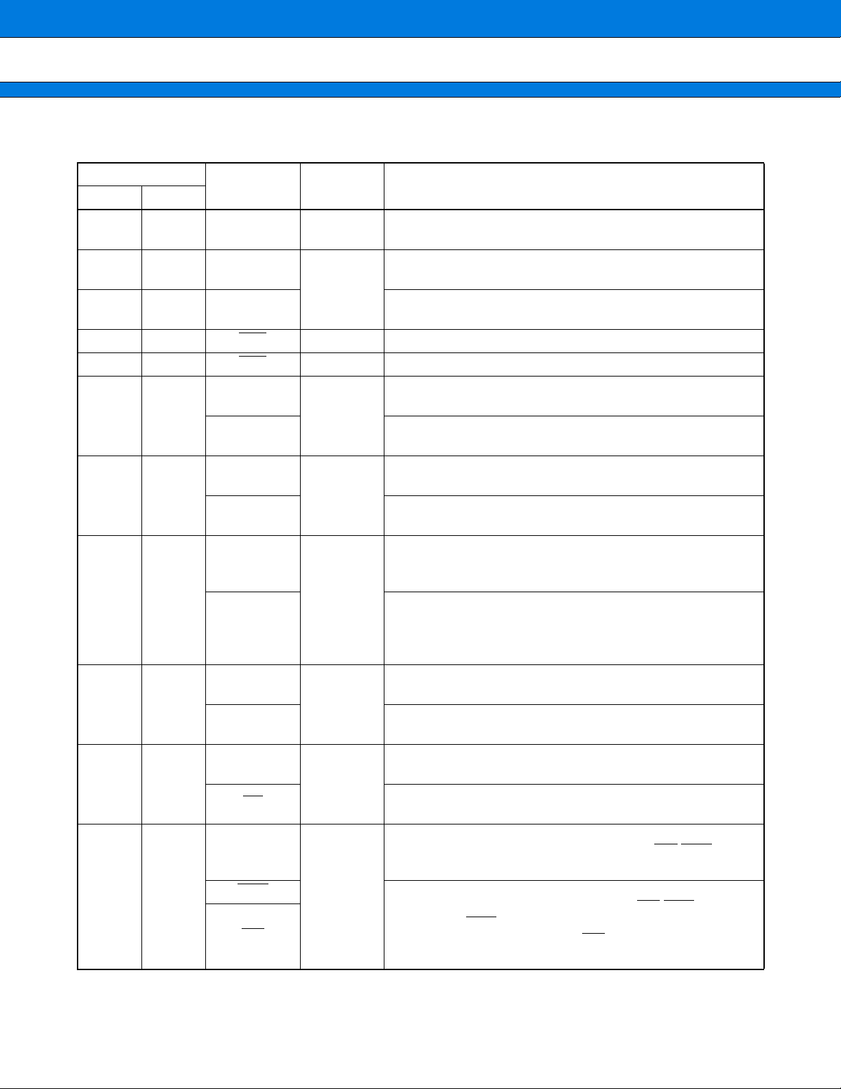
PRODUCT LINEUP
■■■■
MB90F543/F549
Features
MB90F543G (S) /F548G (S)
MB90F549G (S) /F546G (S)
MB90F548GL(S)
CPU F
System clock
ROM
RAM
Clocks
Flash memory
MB90F543/F543G(S)/
F548G(S) / F548GL(S) :
128 K
MB90F549/F549G(S)/
F546G(S) : 256 K
MB90F548G(S)/F548GL(S):
4 Kbytes
MB90F543/F549/F543G (S) /
F549G(S) : 6 Kbytes
MB90F546G(S) : 8 Kbytes
MB90F543/F549/F543G/
F548G/F549G/F546G/F548GL
: Two clocks system
MB90F543GS/F548GS/
F549GS/F546GS/F548GLS
: One clock system
On-chip PLL clock multiplier (×1, ×2, ×3, ×4, 1/2 when PLL stop)
Minimum instruction exection time : 62.5 ns (4 MHz osc. PLL × 4)
Mask ROM :
MB90547G(S): 64 K
MB90543G(S)/548G(S):
128 K
MB90549G(S): 256 K
MB90547G(S): 2 Kbytes
MB90548G(S): 4 Kbytes
MB90543G(S)/549G(S):
6 Kbytes
MB90543G/547G/548G/
549G : Two clocks system
MB90543GS/547GS/
548GS/549GS
: One clock system
Operating voltage
range
Temperature range
MB90F543/F549: −40 °C to 85 °C
Other than MB90F543/F549: −40 °C to 105 °C
MB90543G (S) *
MB90547G (S) *
MB90548G (S)
MB90549G (S)
2
MC-16LX CPU
*5
1
1
MB90V540/V540G
External
8 Kbytes
Two clocks system*
Package QFP100, LQFP100 PGA-256
Emulator-specify
power supply
*3
None
Full duplex double buffer
UART0
Support asynchronous/synchronous (with start/stop bit) transfer
Baud rate : 4808/5208/9615/10417/19230/38460/62500/500000 bps (asynchronous)
500 K/1 M/2 Mbps (synchronous) at System clock = 16 MHz
Full duplex double buffer
UART1
(SCI)
Asynchronous (start-stop synchronized) and CLK-synchronous communication
Baud rate : 1202/2404/4808/9615/19230/31250/38460/62500 bps (asynchronous)
62.5 K/125 K/250 K/500 K/1 M/2 Mbps (synchronous) at 6, 8, 10, 12, 16 MHz
Transfer can be started from MSB or LSB
Serial I/O
Supports internal clock synchronized transfer and external clock synchronized transfer
Supports positive-edge and nagative-edge clock synchronization
Baud rate : 31.25 K/62.5 K/125 K/500 K/1 Mbps at System clock = 16 MHz
10-bit or 8-bit resolution
A/D Converter
8 input channels
Conversion time : 26.3 µs (per one channel)
2
(Continued)
4

MB90540/540G/545/545G Series
(Continued)
MB90543G (S) *
MB90547G (S) *
MB90548G (S)
MB90549G (S)
1
, fsys/23, fsys/25 (fsys = System clock frequency)
2
, fsys/24, fsys/26, fsys/28 (fsys = System clock freq.)
Features
16-bit Reload Timer
(2 channels)
16-bit I/O Timer
16-bit Output Compare
(4 channels)
16-bit Input Capture
(8 channels)
MB90F543/F549
MB90F543G (S) /F548G (S)
MB90F549G (S) /F546G (S)
MB90F548GL(S)
Operation clock frequency : fsys/2
Supports External Event Count function
Signals an interrupt when overflow
Supports Timer Clear when a match with Output Compare (Channel 0)
Operation clock freq. : fsys/2
Signals an interrupt when a match with 16-bit I/O Timer
Four 16-bit compare registers
A pair of compare registers can be used to generate an output signal
Rising edge, falling edge or rising & falling edge sensitive
Four 16-bit Capture registers
Signals an interrupt upon external event
Supports 8-bit and 16-bit operation modes
Eight 8-bit reload counters
8/16-bit
Programmable
Pulse Generator
(4 channels)
Eight 8-bit reload registers for L pulse width
Eight 8-bit reload registers for H pulse width
A pair of 8-bit reload counters can be configured as one 16-bit reload counter or as 8-bit
prescaler plus 8-bit reload counter
4 output pins
Operation clock freq. : fsys, fsys/2
1
, fsys/22, fsys/23, fsys/24 or 128 µs@fosc = 4 MHz
(fsys = System clock frequency, fosc = Oscillation clock frequency)
Conforms to CAN Specification Version 2.0 Part A and B
CAN Interface
MB90540 series
: 2 channels
MB90545 series
: 1 channel
Automatic re-transmission in case of error
Automatic transmission responding to Remote Frame
Prioritized 16 massage buffers for data and ID’s supports multipe massages
Flexible configuration of acceptance filtering :
Full bit compare/Full bit mask/Two partial bit masks
Supports up to 1 Mbps
32 kHz Sub-clock Sub-clock for low power operation
External Interrupt
(8 channels)
External bus
interface
Can be programmed edge sensitive or level sensitive
External access using the selectable 8-bit or 16-bit bus is enabled
(external bus mode.)
Virtually all external pins can be used as general purpose I/O
I/O Ports
All push-pull outputs and schmitt trigger inputs
Bit-wise programmable as input/output or peripheral signal
Sub-clock for 32 kHz Sub clock low power operation
Supports automatic programming, Embeded Algorithm TM
Write/Erase/Erase-Suspend/Erase-Resume commands
A flag indicating completion of the algorithm
Flash Memory
Number of erase cycles : 10,000 times
Data retention time : 10 years
Boot block configuration
Erase can be performed on each block
Block protection by externally programmed voltage
*1 : Under development
*2 : If the one clock system is used, equip X0A and X1A with clocks from the tool side.
1
1
*4
MB90V540
MB90V540G
5

MB90540/540G/545/545G Series
*3 : It is setting of DIP switch S2 when Emulation pod (MB2145-507) is used.Please refer to the MB2145-507
hardware manual (2.7 Emulator-specific Power Pin) about details.
*4 : Embedded Algorithm is a trade mark of Advanced Micro Devices Inc.
*5 : OPERATING VOLTAGE RANGE
Products Operation guarantee range
MB90F543/F549/F543G(S)/F546G(S)/F548G(S)/
MB90549G(S)/F549G(S)/V540/V540G
MB90F548GL(S)/543G(S)*
1
/547G(S)*1/548G(S) 3.5 V to 5.5 V
4.5 V to 5.5 V
6

PIN ASSIGNMENT
■■■■
MB90540/540G/545/545G Series
(TOP VIEW)
P20/A16
P21/A17
P22/A18
P23/A19
P24/A20
P25/A21
P26/A22
P27/A23
P30/ALE
P31/RD
V
SS
P32/WRL/WR
P33/WRH
P34/HRQ
P35/HAK
P36/RDY
P37/CLK
P40/SOT0
P41/SCK0
P42/SIN0
P43/SIN1
P44/SCK1
V
CC
P45/SOT1
P46/SOT2
P47/SCK2
P50/SIN2
P51/INT4
P52/INT5
P17/AD15
P16/AD14
P15/AD13
P14/AD12
P13/AD11
P12/AD10
P11/AD09
P10/AD08
P07/AD07
P06/AD06
P05/AD05
P04/AD04
P03/AD03
P02/AD02
99989796959493929190898887868584838281
100
1
2
3
4
5
6
7
8
9
10
11
12
13
14
15
16
17
18
19
20
21
22
23
24
25
26
27
C
28
29
30
31323334353637383940414243444546474849
CC
P01/AD01
P00/AD00
V
X1X0V
SS
50
80
79
78
77
76
75
74
73
72
71
70
69
68
67
66
65
64
63
62
61
60
59
58
57
56
55
54
53
52
51
X0A
X1A
PA0
RST
P97/RX1
P96/TX1
P95/RX0
P94/TX0
P93/INT3
P92/INT2
P91/INT1
P90/INT0
P87/TOT1
P86/TIN1
P85/OUT1
P84/OUT0
P83/PPG3
P82/PPG2
P81/PPG1
P80/PPG0
P77/OUT3/IN7
P76/OUT2/IN6
P75/IN5
P74/IN4
P73/IN3
P72/IN2
P71/IN1
P70/IN0
HST
MD2
P53/INT6
P54/INT7
P55/ADTG
CC
AV
SS
AV
AVRL
AVRH
P60/AN0
P61/AN1
(FPT-100P-M06)
SS
V
P62/AN2
P63/AN3
P64/AN4
P65/AN5
P66/AN6
P67/AN7
P56/TIN0
P57/TOT0
MD0
MD1
7

MB90540/540G/545/545G Series
(TOP VIEW)
P21/A17
P20/A16
P17/AD15
P16/AD14
P15/AD13
P14/AD12
P13/AD11
P12/AD10
P11/AD09
P10/AD08
P07/AD07
P06/AD06
P05/AD05
P04/AD04
P03/AD03
P02/AD02
P01/AD01
100999897969594939291908988878685848382818079787776
CC
X1X0VSSX0A
P00/AD00
V
X1A
PA0
P22/A18
P23/A19
P24/A20
P25/A21
P26/A22
P27/A23
P30/ALE
P31/RD
V
P32/WRL/WR
P33/WRH
P34/HRQ
P35/HAK
P36/RDY
P37/CLK
P40/SOT0
P41/SCK0
P42/SIN0
P43/SIN1
P44/SCK1
V
P45/SOT1
P46/SOT2
P47/SCK2
SS
CC
1
2
3
4
5
6
7
8
9
10
11
12
13
14
15
16
17
18
19
20
21
22
23
24
25
C
26272829303132333435363738394041424344454647484950
P51/INT4
P52/INT5
P50/SIN2
P53/INT6
P54/INT7
P55/ADTG
CC
AV
AVRL
AVRH
SS
AV
P60/AN0
P61/AN1
SS
V
P62/AN2
P63/AN3
P64/AN4
P65/AN5
P66/AN6
P67/AN7
P56/TIN0
P57/TOT0
MD0
MD1
MD2
HST
75
RST
74
P97/RX1
73
P96/TX1
72
P95/RX0
71
P94/TX0
70
P93/INT3
69
P92/INT2
68
P91/INT1
67
P90/INT0
66
P87/TOT1
65
P86/TIN1
64
P85/OUT1
63
P84/OUT0
P83/PPG3
62
61
P82/PPG2
60
P81/PPG1
59
P80/PPG0
58
P77/OUT3/IN7
57
P76/OUT2/IN6
56
P75/IN5
55
P74/IN4
54
P73/IN3
53
P72/IN2
52
P71/IN1
51
P70/IN0
(FPT-100P-M05)
8
PIN DESCRIPTION
■■■■
MB90540/540G/545/545G Series
Pin No.
*2
LQFP
80
81
78 80 X0A
77 79 X1A
75 77 RST
50 52 HST
83 to 90 85 to 92
91 to 98 93 to 100
99 to 6 1 to 8
QFP
82
83
*1
P00 to P07
AD00 to AD07
P10 to P17
AD08 to AD15
P20 to P27
A16 to A23
Pin name Circuit type Function
X0
X1
A
(Oscillation)
A
(Oscillation)
B External reset request input pin
C Hardware standby input pin
I
I
I
High speed crystal oscillator input pins
Low speed crystal oscillator input pins. For the one clock sys-
tem parts, perfom external pull-down processing.
Low speed crystal oscillator input pins. For the one clock sys-
tem parts, leave it open.
General I/O port with programmable pullup. This function is
enabled in the single-chip mode.
I/O pins for 8 lower bits of the external address/data bus. This
function is enabled when the external bus is enabled.
General I/O port with programmable pullup. This function is
enabled in the single-chip mode.
I/O pins for 8 higher bits of the external address/data bus. This
function is enabled when the external bus is enabled.
General I/O port with programmable pullup. In external bus
mode, this function is valid when the corresponding bits in the
external address output control resister (HACR) are set to “1”.
8-bit I/O pins for A16 to A23 at the external address/data bus.
In external bus mode, this function is valid when the corresponding bits in the external address output control resister
(HACR) are set to “0”.
79
810
10 12
P30
ALE
P31
RD
P32
WRL
WR
General I/O port with programmable pullup. This function is
I
I
I
enabled in the single-chip mode.
Address latch enable output pin. This function is enabled
when the external bus is enabled.
General I/O port with programmable pullup. This function is
enabled in the single-chip mode.
Read strobe output pin for the data bus. This function is en-
abled when the external bus is enabled.
General I/O port with programmable pullup. This function is
enabled in the single-chip mode or when the WR
put is disabled.
Write strobe output pin for the data bus. This function is enabled when both the external bus and the WR
are enabled. WRL
of the data bus in 16-bit access. WR
for the 8 bits of the data bus in 8-bit access.
is write-strobe output pin for the lower 8 bits
is write-strobe output pin
/WRL pin out-
/WRL pin output
(Continued)
9

MB90540/540G/545/545G Series
Pin No.
*2
LQFP
11 13
12 14
13 15
14 16
15 17
QFP
*1
Pin name
P33
WRH
P34
HRQ
P35
HAK
P36
RDY
P37
CLK
Circuit
type
I
I
I
I
H
Function
General I/O port with programmable pullup. This function is
enabled in the single-chip mode, external bus 8-bit mode or
when WRH
Write strobe output pin for the 8 higher bits of the data bus.
This function is enabled when the external bus is enabled,
when the external bus 16-bit mode is selected, and when the
WRH
General I/O port with programmable pullup. This function is
enabled in the single-chip mode or when the hold function is
disabled.
Hold request input pin. This function is enabled when both the
external bus and the hold functions are enabled.
General I/O port with programmable pullup. This function is
enabled in the single-chip mode or when the hold function is
disabled.
Hold acknowledge output pin. This function is enabled when
both the external bus and the hold functions are enabled.
General I/O port with programmable pullup. This function is
enabled in the single-chip mode or when the external ready
function is disabled.
Ready input pin. This function is enabled when both the
external bus and the external ready functions are enabled.
General I/O port with programmable pullup. This function is
enabled in the single-chip mode or when the CLK output is disabled.
CLK output pin. This function is enabled when both the
external bus and CLK outputs are enabled.
pin output is disabled.
output pin is enabled.
10
16 18
17 19
18 20
19 21
P40
SOT0
P41
SCK0
P42
SIN0
P43
SIN1
General I/O port. This function is enabled when UART0
G
G
G
G
disables the serial data output.
Serial data output pin for UART0. This function is enabled
when UART0 enables the serial data output.
General I/O port. This function is enabled when UART0
disables serial clock output.
Serial clock I/O pin for UART0. This function is enabled when
UART0 enables the serial clock output.
General I/O port. This function is always enabled.
Serial data input pin for UART0. Set the corresponding Port
Direction Register to input if this function is used.
General I/O port. This function is always enabled.
Serial data input pin for UART1. Set the corresponding Port
Direction Register to input if this function is used.
(Continued)

MB90540/540G/545/545G Series
Pin No.
*2
LQFP
20 22
22 24
23 25
24 26
QFP
*1
Pin name
P44
SCK1
P45
SOT1
P46
SOT2
P47
SCK2
P50
Circuit
type
G
G
G
G
Function
General I/O port. This function is enabled when UART1
disables the clock output.
Serial clock pulse I/O pin for UART1. This function is
enabled when UART1 enables the serial clock output.
General I/O port. This function is enabled when UART1
disables the serial data output.
Serial data output pin for UART1. This function is enabled when
UART1 enables the serial data output.
General I/O port. This function is enabled when the Extended
I/O serial interface disables the serial data output.
Serial data output pin for the Extended I/O serial interface. This
function is enabled when the Extended I/O serial interface enables the serial data output.
General I/O port. This function is enabled when the Extended
I/O serial interface disables the clock output.
Serial clock pulse I/O pin for the Extended I/O serial interface .
This function is enabled when the Extended I/O serial interface
enables the Serial clock output.
General I/O port. This function is always enabled.
26 28
27 to 30 29 to 32
31 33
36 to 39 38 to 41
41 to 44 43 to 46
45 47
SIN2
P51 to P54
INT4 to INT7
P55
ADTG
P60 to P63
AN0 to AN3
P64 to P67
AN4 to AN7
P56
TIN0
D
D
D
E
E
D
Serial data input pin for the Extended I/O serial interface . Set
the corresponding Port Direction Register to input if this function is used.
General I/O port. This function is always enabled.
External interrupt request input pins for INT4 to INT7. Set the
corresponding Port Direction Register to input if this function is
used.
General I/O port. This function is always enabled.
Trigger input pin for the A/D converter. Set the corresponding
Port Direction Register to input if this function is used.
General I/O port. This function is enabled when the analog
input enable register specifies a port.
Analog input pins for the 8/10-bit A/D converter. This function is
enabled when the analog input enable register specifies A/D.
General I/O port. The function is enabled when the analog
input enable register specifies a port.
Analog input pins for the 8/10-bit A/D converter. This function is
enabled when the analog input enable register specifies A/D.
General I/O port. This function is always enabled.
Event input pin for the 16-bit reload timers 0. Set the
corresponding Port Direction Register to input if this function is
used.
(Continued)
11

MB90540/540G/545/545G Series
Pin No.
*2
LQFP
46 48
51 to 56 53 to 58
57 , 58 59 , 60
59 , 62 61 to 64
QFP
*1
Pin name
P57
TOT0
P70 to P75
IN0 to IN5
P76 , P77
OUT2 , OUT3
IN6 , IN7
P80 to P83
PPG0 to
PPG3
Circuit
type
D
D
D
D
Function
General I/O port. This function is enabled when the 16-bit
reload timers 0 disables the output.
Output pin for the 16-bit reload timers 0. This function is
enabled when the 16-bit reload timers 0 enables the output.
General I/O ports. This function is always enabled.
Trigger input pins for input captures ICU0 to ICU5. Set the cor-
responding Port Direction Register to input if this
function is used.
General I/O ports. This function is enabled when the OCU
disables the waveform output.
Event output pins for output compares OCU2 and OCU3. This
function is enabled when the OCU enables the waveform output.
Trigger input pins for input captures ICU6 and ICU7. Set the
corresponding Port Direction Register to input and disable the
OCU waveform output if this function is used.
General I/O ports. This function is enabled when 8/16-bit PPG
disables the waveform output.
Output pins for 8/16-bit PPGs. This function is enabled when
8/16-bit PPG enables the waveform output.
63 , 64 65 , 66
65 67
66 68
67 to 70 69 to 72
71 73
P84 , P85
OUT0 , OUT1
P86
TIN1
P87
TOT1
P90 to P93
INT0 to INT3
P94
TX0
General I/O ports. This function is enabled when the OCU
disables the waveform output.
D
D
D
D
D
Waveform output pins for output compares OCU0 and OCU1.
This function is enabled when the OCU enables the waveform
output.
General I/O port. This function is always enabled.
Input pin for the 16-bit reload timers 1. Set the
corresponding Port Direction Register to input if this function is
used.
General I/O port. This function is enabled when the 16-bit
reload timers 0 disables the output.
Output pin for the 16-bit reload timers 1.This function is
enabled when the 16-bit reload timers 1 enables the output.
General I/O port. This function is always enabled.
External interrupt request input pins for INT0 to INT3. Set the
corresponding Port Direction Register to input if this function is
used.
General I/O port. This function is enabled when CAN0 disables
the output.
TX output pin for CAN0. This function is enabled when CAN0
enables the output.
(Continued)
12

(Continued)
Pin No.
*2
LQFP
QFP
*1
Pin name
MB90540/540G/545/545G Series
Circuit
type
Function
72 74
73 75
74 76
P95
D
RX0
P96
D
TX1
P97
D
RX1
General I/O port. This function is always enabled.
RX input pin for CAN0 Interface. When the CAN function is
used, output from the other functions must be stopped.
General I/O port. This function is enabled when CAN1 disables
the output.
TX output pin for CAN1. This function is enabled when CAN1
enables the output (only MB90540 series) .
General I/O port. This function is always enabled.
RX input pin for CAN1 Interface. When the CAN function is
used, output from the other functions must be stopped (only
MB90540 series) .
76 78 PA0 D General I/O port. This function is always enabled.
Power supply pin for the A/D Converter. This power supply
must be turned on or off while a voltage higher than or equal to
AV
CC is applied to VCC.
Power supply pin for the A/D Converter.
External reference voltage input pin for the A/D Converter.
This power supply must be turned on or off while a voltage
higher than or equal to AVRH is applied to AV
CC.
32 34 AV
CC
35 37 AVSS
33 35 AVRH
Power
supply
Power
supply
Power
supply
34 36 AVRL
47
48
49
50
MD0
MD1
49 51 MD2 F
25 27 C
21, 82 23, 84 V
9, 40, 79
11, 42,
81
CC
V
SS
*1 : FPT-100P-M06
*2 : FPT-100P-M05
Power
supply
C
Power
supply
Power
supply
External reference voltage input pin for the A/D Converter.
Input pins for specifying the operating mode. The pins must be
directly connected to V
CC or VSS.
Input pin for specifying the operating mode. The pin must be
directly connected to V
CC or VSS.
Power supply stabilization capacitor pin. It should be connected externally to an 0.1 µF ceramic capacitor.
Input pin for power supply (5.0 V) .
Input pin for power supply (0.0 V) .
13

MB90540/540G/545/545G Series
I/O CIRCUIT TYPE
■■■■
Circuit type Diagram Remarks
• High-speed oscillation feedback resistor
X1, X1A
X0, X0A
A
Standby control signal
: 1 MΩ approx.
• Low-speed oscillation feedbac k resistor
: 10 MΩ approx.
• Hysteresis input
• Pull-up resistor : 50 kΩ approx.
B
R (Pull-up)
R
HYS input
• Hysteresis input
C
R
HYS input
• CMOS level output
VCC
P-ch
D
R
N-ch
HYS input
• CMOS Hysteresis input
(Continued)
14

MB90540/540G/545/545G Series
Circuit type Diagram Remarks
• CMOS level output
CC
V
P-ch
N-ch
E
P-ch
Analog input
N-ch
R
R
HYS input
HYS input
• CMOS Hysteresis input
• Analog input
• Hysteresis input
• Pull-down Resistor : 50 kΩ approx.
(except FLASH devices)
F
R (Pull-down)
• CMOS level output
• CMOS Hysteresis input
• TTL level input (FLASH devices in
CC
V
P-ch
N-ch
FLASH writer mode only)
G
R
R
T
HYS input
TTL level input
(Continued)
15

MB90540/540G/545/545G Series
(Continued)
Circuit type Diagram Remarks
• CMOS level output
• CMOS Hysteresis input
• Programmable pull-up resistor :
VCC
H
VCC
CNTL
P-chP-ch
N-ch
50 kΩ approx.
R
HYS input
• CMOS level output
• CMOS Hysteresis input
• TTL level input (FLASH devices in
VCC
P-ch
I
R
R
CNTL
CC
V
P-ch
N-ch
T
FLASH writer mode only)
• Programmable pullup resistor :
50 kΩ approx.
HYS input
TTL level input
16

MB90540/540G/545/545G Series
HANDLING DEVICES
■■■■
(1) Preventing latch-up
CMOS IC chips may suffer latch-up under the following conditions :
• A voltage higher than V
• A voltage higher than the rated voltage is applied between V
• The AVcc power supply is applied before the VCC voltage.
Latch-up may increase the power supply current drastically, causing thermal damage to the device.
For the same reason, care must also be tak en in not allowing the analog po wer-supply v oltage (AV
exceed the digital power-supply voltage.
(2) Handling unused pins
Leaving unused input pins open may result in misbehavior or latch up and possible permanent damage of the
device. Theref or the y m ust be pulled up or pulled down through resistors . In this case those resistors should be
more than 2 kΩ.
Unused bi-directional pins should be set to the output state and can be left open, or the input state with the
above described connection.
(3) Using external clock
To use external clock, drive X0 pin only and leave X1 pin unconnected.
Below is a diagram of how to use external clock.
CC or lower than VSS is applied to an input or output pin.
CC and VSS.
CC, A VRH) to
MB90540/545 Series
X0
Open
X1
(4) Use of the sub-clock
Use one clock system parts when the sub-clock is not used. In that case, pull-down the pin X0A and leave the
pin X1A open. When using two clock system parts, a 32 kHz oscillator has to be connected to the X0A and X1A
pins.
CC/VSS
(5) Power supply pins (V
In products with multiple V
)
CC or VSS pins, the pins of a same potential are internally connected in the device to
avoid abnormal operations including latch-up. However you must connect the pins to an external power and a
ground line to lower the electro-magnetic emission le vel to pre v ent abnormal operation of strobe signals caused
by the rise in the ground level, and to conform to the total current rating.
Make sure to connect V
It is recommended to provide a bypass capacitor of around 0.1 µF between V
CC and VSS pins via the lowest impedance to power lines.
CC and VSS pins near the device.
VCC
VSS
VCC
VSS
VSS
VCC
VSS
MB90540/545
Series
VCC
VCC
VSS
17

MB90540/540G/545/545G Series
(6) Pull-up/down resistors
The MB90540/545 Series does not support internal pull-up/down resistors (except Port0 − Port3 : pull-up resistors) . Use external components where needed.
(7) Crystal Oscillator Circuit
Noises around X0 or X1 pins may be possible causes of abnormal operations. Make sure to provide bypass
capacitors via the shortest distances from X0, X1 pins, crystal oscillator (or ceramic resonator) and ground lines,
and make sure, to the utmost effort, that lines of oscillation circuits do not cross the lines of other circuits.
It is highly recommended to provide a printed circuit board artwork surrounding X0 and X1 pins with a ground
area for stabilizing the operation.
(8) Turning-on Sequence of Power Supply to A/D Converter and Analog Inputs
Make sure to turn on the A/D converter power supply (A V
turning-on the digital power supply (V
CC) .
CC, A VRH, A VRL) and analog inputs (AN0 to AN7) after
Turn-off the digital power after turning off the A/D converter supply and analog inputs. In this case, make sure
that the voltage does not exceed AVRH or AV
CC (turning on/off the analog and digital power supplies simulta-
neously is acceptable) .
(9) Connection of Unused Pins of A/D Converter
Connect unused pins of A/D converter to AV
CC = VCC, AVSS = AVRH = VSS.
(10) N.C. Pin
The N.C. (internally connected) pin must be opened for use.
(11) Notes on Energization
To prevent the internal regulator circuit from malfunctioning, set the voltage rise time during energization at
50 µs or more (0.2 V to 2.7 V) .
18

MB90540/540G/545/545G Series
(12) Indeterminate outputs from ports 0 and 1 (MB90F543/F549/V540/V540G only)
During oscillation setting time of step-down circuit (during a power-on reset) after the power is turned on, the
outputs from ports 0 and 1 become following state.
•If RST
•If RST pin is “L”, the outputs become high-impedance.
Pay attention to the port output timing shown as follow.
•RST pin is “H”
pin is “H”, the outputs become indeterminate.
VCC (Power-supply pin)
PONR (power-on reset) signal
RST (external asynchronous reset) signal
RST (internal reset) signal
Oscillation clock signal
KA (internal operation clock A) signal
KB (internal operation clock B) signal
PORT (port output) signal
Oscillation setting time*
Power-on reset*
Period of indeterminated
2
1
*1 : Power-on reset time : Period of “clock frequency × 217” (Clock frequency of 16 MHz : 8.19 ms)
*2 : Oscillation setting time : Period of “clock frequency × 2
18
” (Clock frequency of 16 MHz : 16.38 ms)
19

MB90540/540G/545/545G Series
•RST pin is “L”
VCC (Power-supply pin)
PONR (power-on reset) signal
RST (external asynchronous reset) signal
RST (internal reset) signal
Oscillation clock signal
KA (internal operation clock A) signal
KB (internal operation clock B) signal
PORT (port output) signal
Oscillation setting time*
Power-on reset*
High-impedance
2
1
*1 : Power-on reset time : Period of “clock frequency × 217” (Clock frequency of 16 MHz : 8.19 ms)
*2 : Oscillation setting time : Period of “cloc k frequency × 2
18
” (Clock frequency of 16 MHz : 16.38 ms)
(13) Initialization
In the device, there are internal registers which are initialized only by a pow er-on reset. T o initialize these registers,
please turn on the power again.
(14) Directions of “DIV A, Ri” and “DIVW A, RWi” instructions
In the Signed multiplication and division instructions (“DIV A, Ri” and “DIVW A, RWi”) , the value of the corresponding bank register (DTB, ADB, USB, SSB) is set in “00
H”.
If the values of the corresponding bank registers (DTB, ADB, USB, SSB) are set to other than “00H”, the remainder
by the execution result of the instruction is not stored in the register of the instruction operand.
(15) Using REALOS
The use of EI
2
OS is not possible with the REALOS real time operating system.
(16) Caution on Operations during PLL Clock Mode
If the PLL clock mode is selected, the microcontroller attempt to be working with the self-oscillating circuit ev en
when there is no external oscillator or external clock input is stopped. Performance of this operation, however,
cannot be guaranteed.
20

BLOCK DIAGRAM
■■■■
X0, X1
X0A, X1A
RST
HST
Clock
Controller
MB90540/540G/545/545G Series
F2MC 16LX
CPU
SOT0
SCK0
SIN0
SOT1
SCK1
SIN1
SOT2
SCK2
SIN2
AV
CC
AVSS
AN0 to AN7
AVRH
AVRL
ADTG
RAM
2 K/4 K/6 K/8 K
ROM/Flash
128 K/256 K/
64K(ROM only)
Prescaler
UART0
Prescaler
UART1
(SCI)
Prescaler
Serial I/O
10-bit A/D
Converter
8 ch.
FMC-16 Bus
16-bit I/O
Timer
16-bit Input
Capture
8 ch.
16-bit Output
Compare
4 ch.
8/16-bit
PPG
4 ch.
CAN
Controller
16-bit Reload
Timer 2 ch.
External
Bus
Interface
IN0 to IN5
IN6/OUT2,
IN7/OUT3
OUT0, OUT1
PPG0 to PPG3
RX0, RX1 *
TX0, TX1 *
TIN0, TIN1
TOT0, TOT1
AD00 to AD15
A16 to A23
ALE
RD
WRL
WRH
HRQ
HAK
RDY
CLK
* : Only the MB90540 series has two channels
External
Interrupt
8 ch.
INT0 to INT7
21
 Loading...