

Page 1

Copyright
io
Address: 598 Gibraltar Drive
Milpitas,CA 95035
Telephone: (408) 935-8800
Declares that product: Model:LifeBook 420D
Complies with Part 15
of the FCC Rules.
This devi ce complies with Pa rt 15 of the FCC r
Opera ti ons is su bj ect to the fo ll owing two con d i t
(1) This devi ce must not be all owed to cause har
i n terferen ce , (2) This devi ce must accept any inte
en ce received , i n cluding interferen ce that may c
u n de s i red opera ti on .
D avid Woo Fu j i t su 2 / 1 8 / 9 7
full na m e co m pa n y dat e
Fu j i t su PC Corpora ti on has made every eVort to en su re
the acc u racy and com p l eteness of this doc u m en t .
However, as on going devel opm ent eVorts are con ti nua lly improving the capabi l i ties of our produ ct s , we
cannot guara n tee the acc u racy of the con tents of t h i s
doc u m en t .We disclaim liabi l i ty for errors , om i s s i on s ,
or futu re ch a n ge s .
LifeBook is a trademark of Fujitsu PC Corporation.
The following are registered trademarks of IBM
Corporation:IBM,IBM PC AT, IBM PS/2.
The following are registered trademarks of Microsoft
Corporation:MS,MS-DOS, Windows NT,Microsoft
Windows forWorkgroups, Windows 95.
PCMCIA is a trademark of the Personal Computer
Memory Card International Association.
Phoenix and the Phoenix logo are registered
trademarks of Phoenix Technologies,Ltd.
Intel Pentium is a trademark of Intel Corporation.
All Kensington Corporation products are registered
trademarks of Kensington Microware Limited.
PC-Doctor is a trademark of watergate.software.inc.
SoftPEG™ is a registered trademark of CompuCore
Multimedia Inc.
LapLink is regi s tered tradem a rk of Traveling Sof t w a re In c .
All other produ cts are tradem a rks or regi s tered
tradem a rks oft h eir re s pective com p a n i e s .
© Copyri ght 1996 Fu j i t su PC Corpora ti on .All ri gh t s
re s erved .No part of this publ i c a ti on may be cop i ed ,
reprodu ced ,or tra n s l a ted ,wi t h o ut pri or wri t ten
con s ent of Fu j i t su PC Corpora ti on .No part of t h i s
p u bl i c a ti on may be stored or tra n s m i t ted in any
el ectronic form wi t h o ut the wri t ten con s ent of
Fu j i t su PC Corpora ti on .
D E C LA RATION OF CONFORMITY
according to FCC Part 15
Responsible Party Name: Fujitsu PC Corporat
Page 2

C A U T I O N
Changes or modification not expressly appro v e d
by Fujitsu PC Corporation could void this user’s
authority to operate the equipment.
FCC Notices
Notice to Users of Radios and Television
These limits are de s i gn ed to provi de re a s on a ble pro tecti on against harmful interferen ce in a re s i den tial install a ti on . This equ i pm ent gen era te s ,u s e s ,and can rad i a te
radio frequ ency en er gy and,i f not install ed and used
in accord a n ce with the instru cti on s ,m ay cause harm f u l
i n terferen ce to radio com mu n i c a ti on s .However, t h ere
is no guara n tee that interferen ce wi ll not occur in a
p a rticular install a ti on .If this equ i pm ent does cause
h a rmful interferen ce to radio or tel evi s i on recepti on ,
wh i ch can be determ i n ed by tu rning the equ i pm ent
oV and on , the user is en co u ra ged to try to correct the
i n terferen ce by one or more of the fo ll owing measu re s :
■
Reori ent or rel oc a te the receiving anten n a .
■
In c rease the sep a ra ti on bet ween the equ i pm ent and
receiver.
■
Con n ect the equ i pm ent into an out l et that is on
a diVerent circuit than the receiver.
■
Consult the dealer or an experienced radio/TV
technician for help.
S h i el ded intercon n ect cables must be em p l oyed wi t h
this equ i pm ent to en su re com p l i a n ce with the pertin ent RF em i s s i on limits governing this devi ce .
If you experience trouble with this equipment please
contact your support representative, toll free at 1-8008FUJITSU (1-800-838-5487) or Fujitsu Computer
Products of America (FCPA),7300 NE Evergreen
Parkway, Hillsboro, OR 97124, telephone
503-681-7300.
DOC (Industry Canada) Notices
Notice to Users of Radios and Television
This Class B digital app a ra tus meets all requ i rem ents
of the Ca n adian In terferen ce - Causing Equ i pm en t
Reg u l a ti on s .
CET app a reil nu m é ri que de la class B re s pecte to utes
les ex i gen ce du Régl em ent sur le matérial bro u i ll eur
du Ca n ad a .
UL Notice(For Authorized Repair Technicians Only)
C AU T I O N : For con ti nu ed pro t ecti on against risk of fi re , rep l ace on ly
with the same type and ra ting fuse.
C AU T I O N :D a n ger of ex p l o s i on if CMOS battery is incorrect ly
rep l aced .Rep l ace on ly with the same or equ iva l ent type recom m en ded
by the manu f actu r er. Di s pose of u s ed batteries according to the
m a nu f actu rer ’ s instru cti on .
WA R N I N G : CMOS Ba t tery may ex p l ode if m i s tre a ted .Do not rech a r ge ,
d i s a s s em ble or dispose ofin fire .
Page 3

T a b l e o f C o n t e n t s
Page 4

T a b l e o f C o n t e n t s
ii
Preface . . . . . . . . . . . . . . . . . . . vi
Section One
Setting Up Your LifeBook 400 Series
Unpacking. . . . . . . . . . . . . . . . . . . . 2
Overview of Features . . . . . . . . . . . . . . 3
Component Identification . . . . . . . . . . . 4
Power Sources. . . . . . . . . . . . . . . . . . 9
Data Security . . . . . . . . . . . . . . . . . . 9
Starting Your Computer for the First Time . 10
User Registration . . . . . . . . . . . . . . . 13
Learning About Your Operating System
and Application Software. . . . . . . . . . 14
Section Two
Using Your LifeBook 400 Series
Using your LifeBook 400 Series
from Fujitsu . . . . . . . . . . . . . . . . 16
Status Indicator Panel. . . . . . . . . . . . . 17
Power Center by Fujitsu. . . . . . . . . . . . 20
Power On . . . . . . . . . . . . . . . . . . . 21
Special Operating System Features . . . 22
Power OV . . . . . . . . . . . . . . . . . . . 23
Restarting the System . . . . . . . . . . . . . 24
Batteries . . . . . . . . . . . . . . . . . . . . 25
Integrated TouchPad Pointing Device . . . . 27
Using the Keyboard . . . . . . . . . . . . . . 29
Floppy Disk Drive . . . . . . . . . . . . . . . 31
CD-ROM Drive . . . . . . . . . . . . . . . . 33
Hard Drive. . . . . . . . . . . . . . . . . . . 35
Power-Saving Modes . . . . . . . . . . . . . 36
Video and Audio Functions. . . . . . . . . . 40
File Transfers. . . . . . . . . . . . . . . . . . 41
Section Three
Configuring Your LifeBook 400 Series
Boot Sequence . . . . . . . . . . . . . . . . . 44
Identifying the Drives . . . . . . . . . . . . . 44
BIOS Setup Utility. . . . . . . . . . . . . . . 45
Navigating Through the Setup Utility . . . . 46
Main Menu – Setting System Parameters . . 48
Exiting from the Main Menu . . . . . . . . . 57
Advanced Menu – Setting Device Controls . 57
Exiting from the Advanced Menu . . . . . . 64
Security Menu . . . . . . . . . . . . . . . . . 65
Exiting from the Security Menu . . . . . . . 67
Power Savings Menu . . . . . . . . . . . . . 67
Exiting from the Power Savings Menu . . . . 69
Boot Menu – Selecting the
Operating System Source . . . . . . . . . 71
Exiting from the Boot Menu . . . . . . . . . 72
Exit Menu – Leaving the Setup Utility . . . . 72
Setting Up Your Save-To-Disk
File Allocation . . . . . . . . . . . . . . . 73
Page 5

T a b l e o f C o n t e n t s
j
Section Four
User Installable Features
RAM Module . . . . . . . . . . . . . . . . . 76
PCMCIA Cards . . . . . . . . . . . . . . . . 79
Installing a Theft Prevention Lock . . . . . . 82
Optional External Installation of
Floppy Disk Drive . . . . . . . . . . . . . 82
Nickel Metal Hydride Battery Pack. . . . . . 83
Multi-function Bay . . . . . . . . . . . . . . 84
CD-ROM Drive . . . . . . . . . . . . . . . . 85
Removable Floppy Disk Drive . . . . . . . . 86
Installing Devices on the LPT Port . . . . . . 86
Installing Devices on the COM Port . . . . . 86
Installing External Monitors . . . . . . . . . 86
Installing a Mouse or Keyboard . . . . . . . 86
Installing a Replicator Port or
Mini-Docking Station . . . . . . . . . . . 86
Installing Audio Input Devices . . . . . . . . 87
Installing Audio Output Devices . . . . . . . 87
Section Five
Troubleshooting
Identifying the Problem. . . . . . . . . . . . 90
Specific Problems . . . . . . . . . . . . . . . 91
Power On Self Test Messages . . . . . . . . 110
Emergency CD-ROM Tray Release . . . . . 113
Installing and Removing the
Internal Hard Drive . . . . . . . . . . . . 113
Restoring Your Pre-installed Software
from CD-ROM . . . . . . . . . . . . . . 114
Section Six
Care and Maintenance
Care and Maintenance. . . . . . . . . . . . 116
Caring for Your Notebook. . . . . . . . . . 116
Increasing Battery Life . . . . . . . . . . . . 116
Appendices
Appendix A Specifications. . . . . . . . . .
Warranty . . . . . . . . . . . . . . . . . . .
LifeBook 420D Specifications . . . . . . . .
Approvals. . . . . . . . . . . . . . . . . . .
Accessories . . . . . . . . . . . . . . . . . .
Appendix B Glossary. . . . . . . . . . . . .
Index . . . . . . . . . . . . . . . . . . . .
Li feB ook 400 Ser ie s fr o m F u
Page 6

P r e f a c e
Preface
The LifeBook 400 Series from Fujitsu PC
Corporation is a powerful notebook computer.
It is powered by an Intel Pentium microprocessor, has a built-in color display,a CD-ROM
drive and brings the computing power of
desktop personal computers (PCs) to a
portable environment.
This manual explains how to operate your
LifeBook 400 Series’hardware and built-in
system software. The LifeBook 400 Series is
compatible with the IBM PC AT.® Depending
on your model,it comes with Windows® 95,
Windows for Workgroups™ Version 3.11 and
MS-DOS Version 6.22 or only Windows 95
pre-installed.When you first start your notebook, you will be asked to select a single
operating system if both are present.
(See pages 11-13 for more information
on selecting your operating system.)
vi
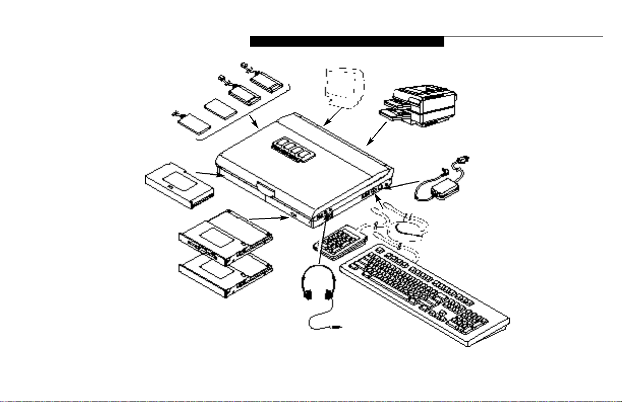
Your LifeBook 400 Series is a completely selfcontained unit with a passive-matrix (DSTN)
color LCD display. It has a powerful interface
that enables it to support a variety of optional
features.(Figure P-1.)
C A U T I O N
When you first turn on your LifeBook
400 Series the Windows 95 Setup screen
will appear. This is true even if you will
be using Windows for Workgroups.
Page 7
L i f e B o o k 4 0 0 S e r i e s f r o m F u j i t s u
j
e P-1 LifeBook 400 Se
with both Fujitsu
Third Party Opt
Life B ook 40 0 Ser ie s fr om F u
Figur
Page 8
P r e f a c e
Conventions Used in the Guide
In this manual, figures which show screens are
intended as examples only,and screen and file
names may diVer in actual use.
Messages displayed by your LifeBook 400 Series
appear in Courier type.
Example: Starting MS-DOS
Commands that you enter into your notebook
using the keyboard appear in Courier type.
Example: C : > D I R / P
Keyboard keys are shown in boldface
Helvetica type.
Example: Fn, F1, Esc, and Ctrl.
Pages with additional information about a specific topic are cross-referenced within the text.
Example: (See page xx.)
viii
P O I N T
The point icon highlights information
that will enhance your understanding of
the subject material.
C A U T I O N
The caution icon highlights information
that is important to your safety, to the
safe operation of your notebook, or to
the integrity of your files. Please read all
caution information carefully.
Page 9

Setting Up Your LifeBook 400 Series
Unpacking . . . . . . . . . . . . . . . . . . . 2
Overview of Features . . . . . . . . . . . . . 3
Component Identification . . . . . . . . . . . 4
Power Sources . . . . . . . . . . . . . . . . . 9
Data Security. . . . . . . . . . . . . . . . . . 9
Starting Your Notebook for the First Time . . 10
User Registration . . . . . . . . . . . . . . . 13
Learning About Your Operating System
and Application Software. . . . . . . . . . . 14
S e c t i o n
Page 10
S e c t i o n O n e
2
Section ONE
Setting Up Your LifeBook 400
Series from Fujitsu
This section describes how to set up your
LifeBook 400 Series from Fujitsu. We strongly
recommend that you read it before using your
notebook – even if you are already familiar with
notebook computers.
Unpacking
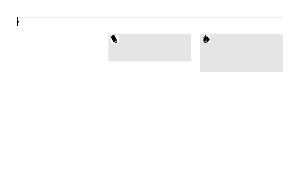
When you receive your notebook,unpack it
carefully, and compare the parts you have
received with the items listed below.
For a standard configuration you should have:
■
L i fe Book 400 Series from Fu j i t su .( F i g u re 1-1.)
■
ACAdapter with AC power cord (located in
the accessories box).(Figure 1-2.)
■
Modular 10-speed CD-ROM Drive (already
installed in your notebook).
■
Modular 3.5" Floppy Disk Drive (located in
the accessories box).(Figure 1-3.)
■
User’s Guide.
■
Registration card and customer
information pack.
■
Microsoft Windows 95 Manual.
■
Additional equipment and documentation
depending on the option package you
have purchased.
Figure 1-1 LifeBook 400 Series Notebook
Figure 1-2 AC Adapter Unit
Figure 1-3 Floppy Disk Drive
Page 11

S e t t i n g U p Y o u r L i f e B o o k 4 0 0 S e r i e s
j
Once you have checked and confirmed that
your notebook system is complete, connect
the AC Adapter and follow the instructions on
page 9 to accept the conditions for using the
LifeBook 400 Series and for selecting the operating system you will use. When you have completed that setup process please complete and
send in your registration card.
Overview of LifeBook 400
Series Features
The LifeBook 400 Series is a compact, yet
powerful notebook computer available with
standard features including:
(See Appendix A, pages 120–123, for detailed
information.)
■
120 MHz Intel Pentium™ processor.
■
8MB EDO RAM standard, expandable to
72MB.
■
11.3" passive-matrix (DSTN) color display
with 800 x 600 resolution.
■
1MB Video RAM.
■
Built-in 1.0GB hard drive.
■
Multi-function bay which supports
warm swapping of the following:
■
3.5" floppy disk drive (included with
all models).
■
10-speed CD-ROM drive (included with
all models).
■
Nickel Metal Hydride (NiMH) Battery Pack.
■
1 6 - bit Sound Bl a s ter™ - com p a ti ble sound ch i p.
■
Zoom Video port for full motion video
acceleration.
■
Built-in stereo speakers.
■
Two Type II or one Type III PCMCIA slot.
■
IrDA1.0 compatible infrared port for wireless data transfer.
■
Integrated TouchPad Pointing Device for easy
cursor control.
■
External monitor support.
■
Full size keyboard with three dedicated
Windows 95 keys.
■
Hot swap connection for an external
keyboard or an external mouse.
■
Stereo line input jack.
■
Stereo headphone/speaker jack.
■
Standard Pre-installed software:
■
Operating System.
■
LapLink 7.0 for file transfers via modem
cable or infrared port.
■
PC Doctor for system diagnostics.
■
SoftPEG from CompCore,a MPEG-1
video player.
■
Some models may include additional
software.
Li feB ook 400 Ser ie s fr o m F u
Page 12
S e c t i o n O n e
4
Component Identification
For detailed specifications refer to Appendix A
on pages 120–123.
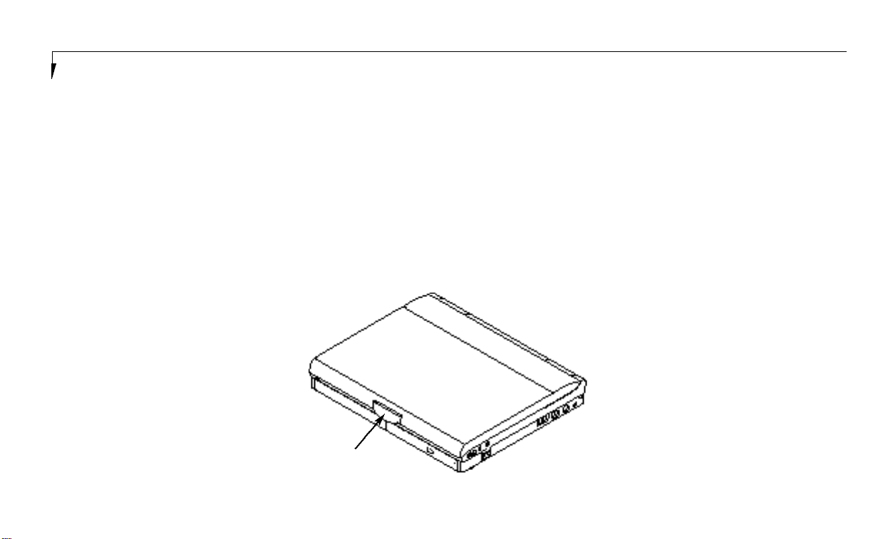
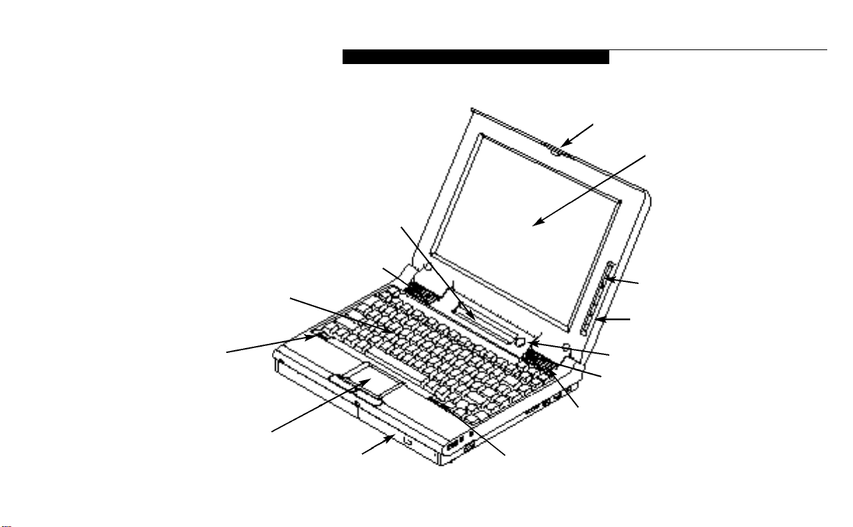
Display Panel Latch
This latch locks and releases the display panel.
LCD Display Panel
This is a color LCD panel with back lighting for
the display of text and graphics.
Brightness Control
The brightness control adjusts the overall intensity of the display screen back lighting.
Contrast Control
The contrast control adjusts the contrast of the
display screen. It is located just below the
brightness control.
Status Indicator Display
LCD display of the status of the power state and
source, Suspend Mode, battery charge, floppy
disk drive activity,hard drive activity,CD-ROM
drive activity,PCMCIA card activity, Caps
Lock, Num Lock and Scroll Lock.
Suspend/Resume Button
The Suspend/Resume Button allows you to
suspend computer activity without turning oV
your notebook power,and to return it to an
active state. This feature saves power,and is
particularly useful when your notebook is
running only on battery power.(See pages
20–21, 36–40,and 67–69 for more information
on Power Management.)
Display Latch
Figure 1-4 Top and Front Panel
Page 13
j
e 1-5 LifeBook 400 Series with Display O
Display Latch
LCD Display
Brightness Control
Contrast Control
Status Indicator Display
Suspend/Resume Button
Closed Cover Switch
Stereo Speaker
Keyboard Removal Tab
Stereo Speaker
Keyboard
Multi-function Bay
TouchPad Pointing Device
Keyboard Removal Tab
S e t t i n g U p Y o u r L i f e B o o k 4 0 0 S e r i e s
Li feB ook 400 Ser ie s fr o m F u
Figur
Page 14
S e c t i o n O n e
6
C A U T I O N
Be sure you know what settings are
active for your Suspend/Resume Button
before you use it because misuse can
result in data loss. (See the Power
Savings Menu of the BIOS Setup Utility
on page 68 for more information.)
Closed Cover Switch
This switch turns oV the LCD back lighting
when the display panel is closed,thus saving
power.
Speakers
The built-in dual speakers output stereo sound
from your notebook.
Keyboard
A full size keyboard with dedicated Windows 95
keys for input into your notebook.
Keyboard Removal Tabs
A pair of tabs which cover screws which hold
the front of the keyboard in place.Lifting the
tabs is only necessary to access the Memory
Expansion Chamber which is under the keyboard. (See pages 76–79 for more information.)
C A U T I O N
Do not attempt to install or remove a
RAM Module if your notebook has been
recently used. The surface area under
the keyboard can be very hot and may
injure you.
TouchPad Pointing Device
A touch sensitive cursor control system with
two click buttons.
Multi-function Bay
This bay accommodates:
■
10-speed CD-ROM drive.
■
3.5" floppy disk drive.
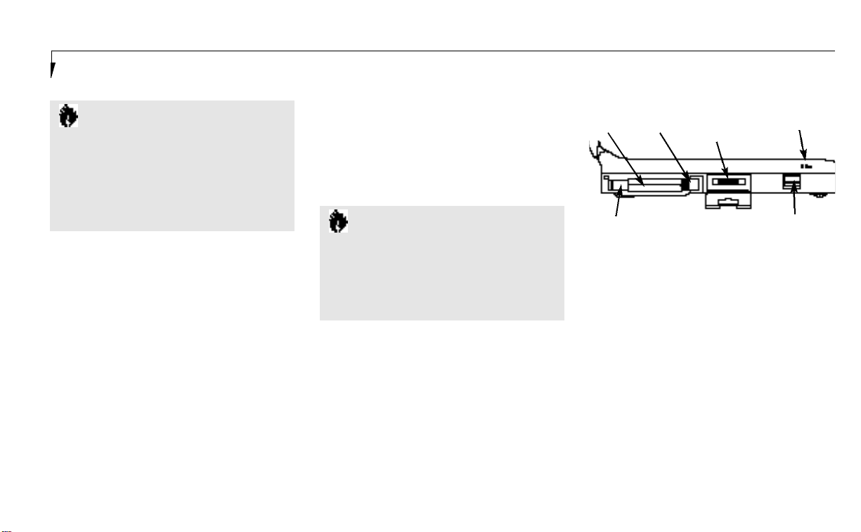
PCMCIA
Card Slot
Lock
Eject
Buttons
Figure 1-6 LifeBook 400 Series Left Side Panel
Optional External
Floppy Disk Drive
Adapter Connector
Built in
Microphone
Battery Eject Button
PCMCIA Card Slot, with Cover,
Lock and Eject Button
The PCMCIA Card Slot allows you to install
two type I or II PCMCIA cards or one type III
PCMCIA card.(See pages 79–81 for more
information on PCMCIA cards.) The button to
the left of the card slot locks the card in place,
and the buttons to the right of the slot ejects
the card(s) from the slot.
E x t e rnal Floppy Disk Drive Adapter Connector
A con n ector for attaching an opti onal ex tern a l
floppy disk drive ad a pter.The ad a pter all ows
you to use your modular floppy disk drive wh en
the mu l ti - f u n cti on bay is being used for another
p u rpo s e .
Page 15
S e t t i n g U p Y o u r L i f e B o o k 4 0 0 S e r i e s
j
Main Battery Eject Button
This releases the Removable Main Nickel
Metal Hydride Battery Pack for removal
and installation.
Built-in Microphone
The built-in microphone allows mono audio
input to your notebook.
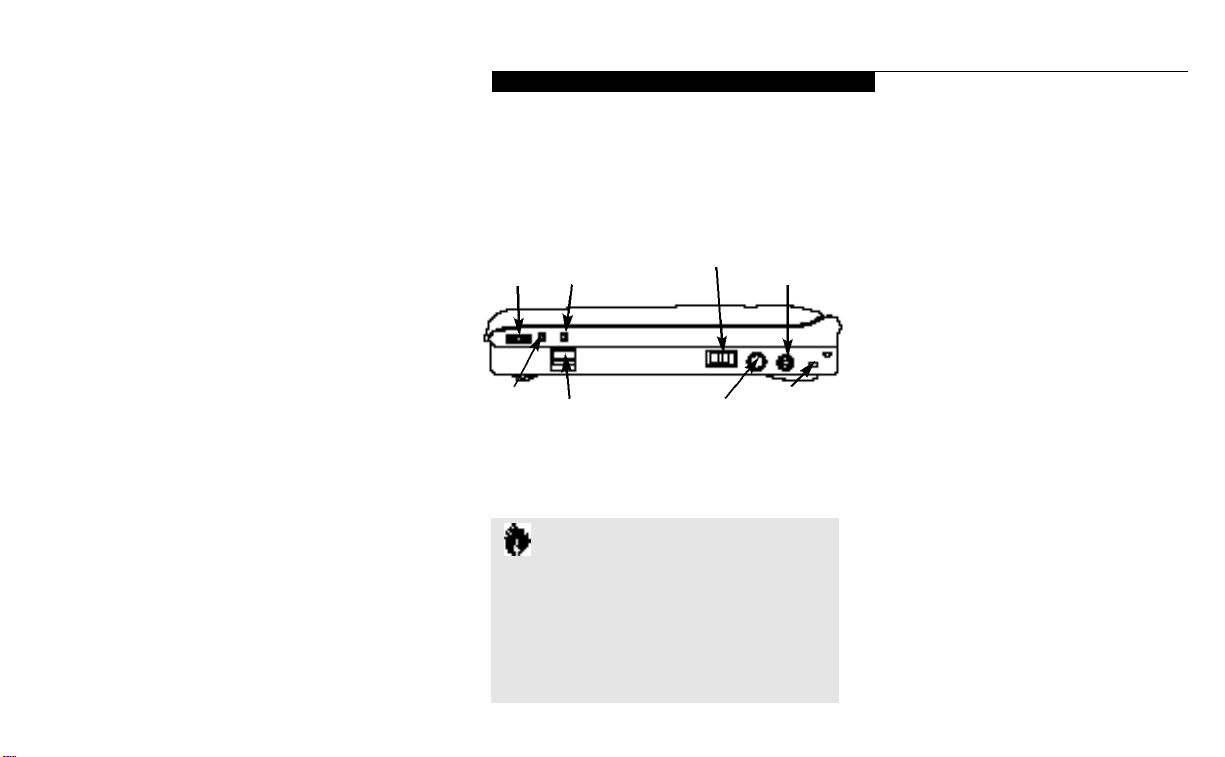
Volume Control
This knob provides hardware control of sound
level of audio outputs from your notebook.
Audio Input Jack
The Audio Input Jack allows you to connect an
external audio source to your notebook,like an
audio cassette player.This jack will not support
an external microphone.
Headphone Jack
You can install headphones or powered external
speakers in the Headphone Jack.
Multi-function Bay Release Button
This is the release to allow removal and installation of devices in the Multi-function Bay.
Power Switch
This switch is the main power switch for
your notebook.
PS/2 Connector
The connector allows you to connect an ext
nal PS/2 keyboard,mouse, or numeric keypa
DC Power Input Connector
The DC Power Input Connector allows you t
plug in the Fujitsu AC Adapter or the option
Fujitsu Auto Adapter.
Theft Prevention Lock Slot
This is a slot that allows you to attach a phy
lock down device.
Serial Interface Connector (COM Port)
The Serial Interface Connector allows you to
connect serial RS-232C devices, such as a se
printer or a serial scanner.
Expansion Bus Connector
This connector is for connection to an optio
port replicator or docking station. The conne
tor cover must be closed and the sliding pane
opened to reveal only the Expansion Bus
Connector when connecting a port replicato
or docking station.
Li feB ook 400 Ser ie s fr o m F u
Volume
Control
Audio
Input
Jack
Headphone
Jack
Multi-function Bay
Release Button
Figure 1-7 LifeBook 400 Series Right Side Panel
Power Switch DC Power
PS/2
Connector
C A U T I O N
There are software volume controls.
The knob setting and the software settings will interact. Software volume
Off will override the knob setting.
(See Volume Control on page 41 for
more information.)
Input Connector
Theft
Prevention
Lock Slot
Page 16
S e c t i o n O n e
8
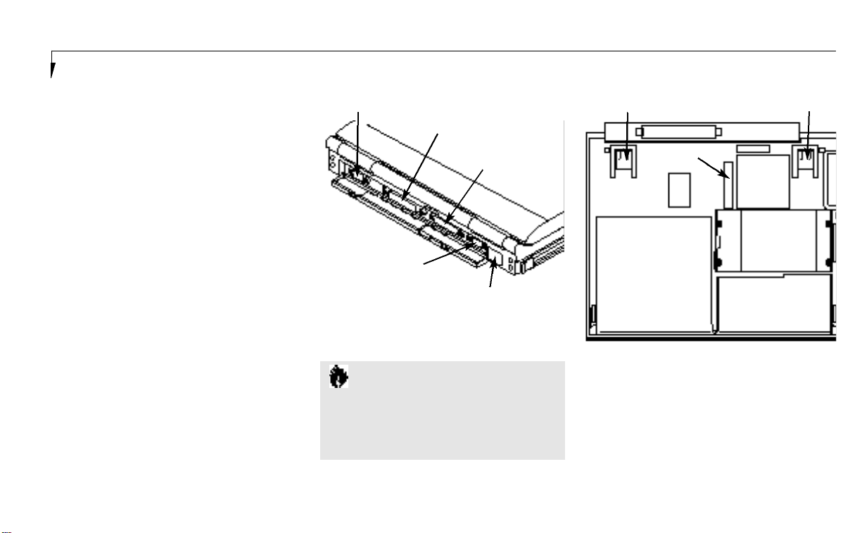
Parallel Interface Connector (LPT Port)
The Parallel Interface Connector allows you
to connect parallel devices, such as a parallel
printer to your notebook.
E x t e rnal SVGA or Hi Res Monitor Connector
This connector allows you to connect an external VGA or SVGA CRT or Hi-Res monitor.
I n f r a re d IrDA Compatible Communication Port
The IrDA compatible Communication Port
allows you to communicate with another IrDA
compatible device without a cable. (See page 41
for more information.)
Tilt Adjustment Feet
These are a pair of feet which flip down and
hold the back of the keyboard approximately
6° higher than the front when resting on a flat
surface.They are designed to make using your
notebook keyboard more comfortable.
Main Unit Label
This label has the model number, serial number
and other information about your notebook.
C A U T I O N
The cover which closes over the connectors on the rear of your notebook can be
damaged if it is left open when your
notebook is moved around.
COM Port
Expansion Bus Connector
LPT Port
Monitor Connector
Infrared Port
Figure 1-8 LifeBook 400 Series Back
Tilt Adjustment Foot Tilt Adjustment Foot
Configuration
Label
Multi-function Bay
Figure 1-9 LifeBook 400 Series Bottom
Main
Unit
Label
Internal
Hard Drive
Chamber
Battery Chamber
Configuration Label
This label has manufacturer information that
you will need to give your support representative so that he or she can help you.It exactly
identifies the version of various component
parts of your notebook.
Page 17

S e t t i n g U p Y o u r L i f e B o o k 4 0 0 S e r i e s
j
Internal Hard Drive Chamber
This chamber houses the internal hard drive.
It should only be accessed for maintenance
by an authorized maintenance provider.
Battery Chamber
This chamber houses the Nickel Metal Hydride
Battery Pack or the optional Lithium ion
Battery Pack.
Power Sources
Your notebook has three possible power
sources: the Nickel Metal Hydride Battery Pack,
the AC Adapter, or the optional Auto Adapter.
Connecting the Power Adapters
The AC Adapter or the AutoAdapter provides
power for operating your notebook and charging the battery pack.(Figure 1-10.)
To Connect the ACAdapter
1.Plug the DC output cable of the AC Adapter
into the DC Power Input Connector on the
right side panel of your notebook.
2.Plug the ACAdapter into an AC
electrical outlet.
To Connect the Optional Auto Adapter
1.Plug the DC output cable into the DC Power
Input Connector on the right side panel of
your notebook.
2. P lug the Auto Con n ector into the c i ga ret te
l i gh terof a car or other veh i cle with the ign iti on key in the On or the Acce s s ories po s i ti on .
Data Security
Your Life Book 400 Series has a built-in hardw
con trol password sec u ri ty fe a tu re that all ows
to pro tect the data stored in your notebook f
u n a ut h ori zed acce s s .Your opera ting sys tem a
s ome app l i c a ti ons have sof t w a re con trol p a s s
word s ec u ri ty fe a tu res that all ows you to pro t
a ll or porti ons of the data stored in your note
book from unaut h ori zed acce s s .
Hardware Data Security Features
When you are using your notebook built-in
hardware control password to gain access
to your notebook the actual password will
not appear on the screen. This is a safety
precaution. The hardware control security
parameters are set from the BIOS Setup Utili
(See Security Menu on pages 65–67 for more
information on setting and clearing passwords
and enabling and disabling built-in
security features.)
C A U T I O N
The Nickel Metal Hydride Battery Pack is
not charged when you purchase your notebook. Initially you will need to connect the
AC Adapter or the Auto Adapter to use it.
It can take up to 3 hours to charge a
B a t t e ry Pack if your notebook is Off or in
Suspend Mode. If your notebook is in use,
it can take up to 9 hours or more to charg e
a Battery Pack.
Li feB ook 400 Ser ie s fr o m F u
Page 18
S e c t i o n O n e
10
Software Data Security Features
The operating system and some applications
have security features that are independent of
the built-in hardware protection features that
are controlled from the BIOS. See your software
documentation for more information about
these features.
C A U T I O N
Software security feature passwords may
not be the same as the hardware security
passwords. Be sure you know which features are controlled from software and
which from hardware or you may lock
yourself out of your own data or lock
up your hardware and not be able to
operate your notebook.
C A U T I O N
Make sure you memorize your passwords, both hardware and software. If
you forget, you may not be able to use
your notebook, and you will have to
contact your service provider and arrange
to have them reset the hardware system
password. See your software manuals for
what to do if you forget your software
security password(s).
Starting Your Notebook for
the First Time
Booting the System
The first time that you turn on your notebook
you will need to attach your AC Adapter as the
battery is not charged when it arrives.We
strongly recommend that you do not attach any
other external devices and do not put any CD
or floppy disk in the drives until you have gone
through the initial power on sequence.
When you turn on your notebook for the first
time it will perform a power on self test and
display some status information on the screen
with a message
Press <F2> for Setup,
if you do nothing the system will read the hard
drive for the operating system software and
the Windows 95 Setup Screen will appear.
(See Power On on pages 21–22 for additional
help.) You will then be stepped through the
condition of use and operating system selection
process.You must complete this initial process
before you will be able to use your notebook.
C A U T I O N
If you have purchased a system which
allows you to use a choice of operating
systems, the Operating System selection
can only be made once. You cannot
change your mind, the option will never
be available again.
Page 19

S e t t i n g U p Y o u r L i f e B o o k 4 0 0 S e r i e s
j
Conditions of Use
The first time you start your notebook you mu s t
con firm your accept a n ce of the copyri ght limit a ti on s for your pre - i n s t a ll ed sof t w a re. If yo u
h ave purch a s ed a unit wh i ch all ows you to
use a ch oi ce of opera ting sys tems you mu s t
ch oose bet ween Wi n dows 95 and Wi n dows for
Work gro u p s.O n ce you have ch o s en your opera ting sys tem you cannot ch a n ge your mind,t h e
o t h er sys tem wi ll not be ava i l a ble to yo u .P l e a s e
dec i de caref u lly.Af ter your notebook com p l ete s
the install a ti on of the opera ting sys tem it wi ll
not ask you again for con firm a ti on of the con d iti ons of use nor to ch oose an opera ting sys tem.
Every LifeBook 400 Series Model has 10 screens
to read carefully and/or answer questions by
typing in information.If your notebook has a
choice to use Windows forWorkgroups there
will be three additional screens. All of the
screens are Windows 95 Setup screens.
You cannot use your notebook until this setup
process is completed. The bottom of each
screen has a < B a c k Button, a N e x t > Button
and a C a n c e l Button which are activated by
the Integrated Touchpad Pointing Device cursor
control and button click. The < B a c k Button
will return you to the previous screen. The
N e x t > Button activates any choices or information you have entered and takes you on to the
next screen. The C a n c e l Button allows you to
stop the setup process. If you stop the process
your notebook will come back to the place in
the Windows 95 Setup where you left oV the
next time you start your machine. The screens
you will be required to respond to are shown
with the required action.
Welcome to Windows Setup
Read and then click on the N e x t > Button.
Regional Settings
Select language, number format, date format
etc. for the operating system to use by movin
cursor up and down the list to the desired
world region shown in the table and then clic
on the N e x t > Button. Use the up arrow Õ
down arrow Ô keys to move down up and
down the text one line at a time.
Keyboard Layout
Select the keyboard language and format you
wish to use by moving cursor up and down t
list to the desired selection shown in the tab
and then click on the N e x t > Button. You can
scroll through the text using the up arrow Õ
and down arrow Ô keys to move down up an
down the text one line at a time.
User Information – Software Licensing
Fill in your name and your company name a
you would like to see it on the software licens
and then click on the N e x t > Button. You m
make an entry in order to continue.
C A U T I O N
When you first turn on your notebook
the Windows 95 Setup screen will
appear. This is true even if you will be
using Windows for Workgroups.
Li feB ook 400 Ser ie s fr o m F u
Page 20
S e c t i o n O n e
12
P O I N T
If your system comes with Windows 95
only, you will find a Recovery CD-ROM
packet in your accessories box. Please
store the packet in a safe place in case
there is a loss of data. (See Restoring
Your Pre-installed Software from CDROM on page 114.)
License of Windows 95
Read carefully and then click on the N e x t >
Button.
License Agreement
Read the agreement carefully.You can scroll
through the text using the Integrated TouchPad
Pointing Device to activate the scroll bar or use
the up arrow Õ and down arrow Ô keys to
move up and down the text one line at a time.
When you finish reading simply point and click
to accept or reject the terms of the agreement
and then click on the N e x t > Button.
P O I N T
If you reject the terms of the license
a g reement the operating system setup will
a b o rt and shutdown your notebook.
When you turn on the system the next
time, it will begin the Setup process again.
Certificate of Authenticity
Look in the box that your notebook came in and
you wi ll find a Wi n dows 95 Certi fic a te of
Aut h en ti c i ty and a Wi n dows 95 Us ers manu a l .O n
the certi fic a te and also on the back of the manu a l
you wi ll find a bar- code with a nu m ber above it.
These nu m bers should be the same.Th ey are yo u r
produ ct code and the nu m ber you should en ter
on the Certi fic a te of Aut h en ti c i ty screen .Wh en
you have en tered the nu m ber ex act ly as shown
t h en cl i ck on the Next> But ton .
C A U T I O N
If your system came with a choice of operating systems, you will need to make back
up disks. (See Create System Disks page
1 3 . )
*Windows Version
To sel ect Wi n dows for Work groups point and
cl i ck on the C h a n g e But ton . To sel ect Wi n dows
95 point and cl i ck on the N e x t > But ton .
( If you sel ect Wi n dows 95 you wi ll go direct ly
to the Con fig u ring the Com p uter Screen . )
*Operating System Choice
To selectWindows for Workgroups point and
click on the Windows for Workgroups selection
and then point and click on the N e x t > Button.
To select Windows 95 point and click on the
Windows 95 selection and then point and click
on the N e x t > Button.
Configuring the Computer
If you have a unit with only Windows 95 or
have selected Windows 95 this screen will
appear when Windows 95 is ready to install.
(If you purchased a LifeBook 400 Series which
only comes with Windows 95 this screen will
appear immediately after the Certificate of
Authenticity Screen.) You may be prompted for
time zone and printer.You do not need to select
a printer at this time.
Page 21

S e t t i n g U p Y o u r L i f e B o o k 4 0 0 S e r i e s
j
Installing Devices
This screen will appear while your notebook
loads the operating system and when it finishes
it will automatically go to the next screen.
C A U T I O N
If you have chosen Windows for
Workgroups please fill out the fulfillment
coupon that came in the box with your
notebook and send it, and the Windows
95 manual, to the address provided.
When the coupon and manual are
received, you will be sent a set of
Windows for Workgroups backup disks
and manual.
o
1. Mail-in Registration – Fill in the registrat
card provided in the box with your LifeBo
400 Series and mail it to Fujitsu.
2.On-line Electronic Registration – Fill out t
registration form behind the Fujitsu Icon o
your Desktop and send it by e-mail.
3. Internet Registration – Use the registratio
utility on the Fujitsu PC Service and Supp
Web Site at www.8fujitsu.com to register y
notebook.
P O I N T
If you do not have enough floppy disks
available during the setup process you
can create system backup disks at any
time. From the Start Menu, select
Accessories, then System Tools, then
Create System Disks.
Li feB ook 400 Ser ie s fr o m F u
*Create System Disks
If your system came with a choice of operating
systems,you will be prompted to create system
disks.We strongly recommend that you make a
system backup so you can restore your factory
installed software in case of data loss. If you
have chosen Windows 95 you will need to backup your operating system and your factory
installed applications and drivers. The backup
will require 40 floppy disks. If you have chosen
Windows forWorkgroups you only need to
backup the factory installed applications and
drivers.The backup will require 9 floppy disks.
Finishing Setup
Click on the Finish Button and your notebook
will restart with the selected Windows operating system ready for normal operation.
User Registration
There are three ways to register your noteb
Page 22

S e c t i o n O n e
14
Learning About Your Operating System
and Application Software
Tutorials
All operating systems and most application
software have tutorials built-in. We highly
recommend that you step through the tutorial
before you use an application, even if you
are familiar with the same application on a
diVerent machine, an earlier version of the
application, or with a similar product.
Manuals
In the accessories box you will find manuals for
Windows 95 and other pre-installed software.
Some software manuals are available on-line
and are not in the box.See the help screens of
your software.We recommend that you review
these manuals for general information on the
use of these applications and to get a basic
understanding of what is covered in the manual,and how it is organized,should questions
arise as you use the applications.
Page 23

Using Your LifeBook 400 Series from Fujitsu
Using Your LifeBook 400 Series from Fujitsu . 16
Status Indicator Panel. . . . . . . . . . . . . 17
Power Center by Fujitsu . . . . . . . . . . . 20
Power On . . . . . . . . . . . . . . . . . . 21
Special Operating System Features . . . . . . 22
Power Off . . . . . . . . . . . . . . . . . . 23
Restarting the System . . . . . . . . . . . . 24
Battery . . . . . . . . . . . . . . . . . . . . 25
Integrated TouchPad Pointing Device. . . . . 27
Using the Keyboard. . . . . . . . . . . . . . 29
Floppy Disk Drive . . . . . . . . . . . . . . . 31
CD-ROM Drive . . . . . . . . . . . . . . . . 33
Hard Drive . . . . . . . . . . . . . . . . . . 35
Power-Saving Modes . . . . . . . . . . . . . 36
Video and Audio Functions . . . . . . . . . . 40
S e c t i o n T w o
Page 24
S e c t i o n T w o
16
Section TWO
Using Your LifeBook
400 Series from Fujitsu
This section describes the indicators, buttons,
connections and operating modes of your
LifeBook 400 Series and their use.
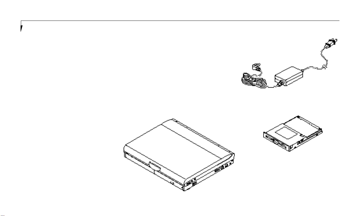
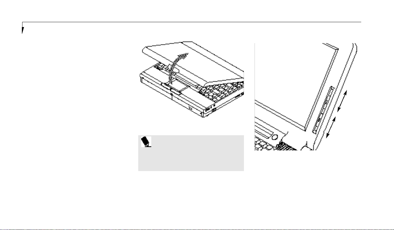
Opening the Unit
Lifting the latch releases the cover and allows
your notebook to be opened.Lift the display
backward until the screen is at a comfortable
viewing angle.(Figure 2-1.)
Adjusting the Built-in Display
Wh en you tu rn on your noteboo k ,you may want
to ad just the bri gh tness level of the screen for be s t
vi s i bi l i ty. To do this, ad just the bri gh tness slider on
the ri ght side ofthe built-in d i s p l ay screen.Yo u
m ay need to ad just the bri gh tness peri od i c a lly
for different opera ting envi ron m en t s .You wi ll
prob a bly want to ad just the con tra s tas well as
the bri gh tn e s s .To do this,use the con trast slider
on the ri ght side of the built-in display screen
just bel ow the bri gh tness con tro l . ( F i g u re 2-2.)
P O I N T
The higher the level of brightness, the
m o re power your notebook will consume,
and the faster the battery will d i s c h a rg e.
Figure 2-1 Opening the LCD Display
Brighter
Less Bright
More Contrast
Less Contrast
Adjusting the Keyboard Angle
On the bottom of your notebook,near the
back,are a pair of feet which flip down and
hold the back of the keyboard about 6° higher
than the front when resting on a flat surface.
Figure 2-2 Display Adjustments
They are designed to make using your notebook more comfortable when using the keyboard. The feet must be folded flat against the
bottom of your notebook when opening or
using a CD-ROM or it will not open or operate
properly. (Figure 1-9 on page 8.)
Page 25
17
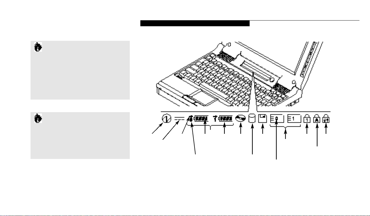
Status Indicator Panel
The Status Indicator LCD Display Panel is
located in the recess just above the keyboard.
(Figure 2-3.) The appropriate indicators
become visible when you use your notebook.
C A U T I O N
Do not operate the CD-ROM drive o r
attempt to open the tray unless your
notebook is sitting on a flat surface and
the adjustment feet are folded against the
bottom of your notebook. Using a CDROM drive when it is not level may damage the drive or prevent proper operation.
C A U T I O N
When you are not using the adjustment
feet be sure that they are folded flat
against the bottom of your notebook.
They could be broken off, or injure
someone, if not used properly.
U s i n g Y o u r L i f e B o o k 4 0 0 S e r i e s
P o w e r
A C
A d a p t e r
C h a rg i n g
I n i d c a t o r
B a t t e ry
L e v e l
B a t t e ry
I d e n t i fie r
U n u s e dB a t t e ry
C D - R O M
Drive
A c c e s s
I n d i c a t o r
H a rd
D r i v e
A c c e s s
I n d i c a t o r
L i fe B o ok 4 0 0 S e r i es f ro m F uj i t s u
F l o p p y
D i s k
D r i v e
A c c e s s
I n d i c a t o r
P C M C I A
C a rd Access
I n d i c a t o r s
P C M C I A
C a rd
I d e n t i fie r
N u m L o c k
I n d i c a t o r
S c roll Lock
I n d i c a t o r
CAP Lock
I n d i c a t o r
Figure 2-3 Status Indicators
Page 26
S e c t i o n T w o
18
Power Indicator
The Power In d i c a tor tells you wh en the sys tem is
opera ti on a l .It is on ste ady wh en there is power
to your noteboo k ,and blinks wh en the sys tem
is in Su s pend Mode.It goes off wh en the sys tem
has en tered Save - to - Disk Mode,has en tered the
Wi n dows 95 shutdown inactivi ty state ,or the
power is tu rn ed off f rom the Power Swi tch .
wh en ei t h er of the ad a pters is active and Off
wh en power comes from the battery alon e .If a
b a t tery is ch a r ging the power ad a pter is active
rega rdless of the set ting of the Power Swi tch .
The AC Ad a pter is also active in the Wi n dows
s hutdown state ,rega rdless of the battery statu s .
If t h ere is no battery ch a r gi n g, and the Power
Swi tch is Off,t h en the AC Ad a pter In d i c a tor and
the Ba t tery Con d i ti on In d i c a tor wi ll all be Off.
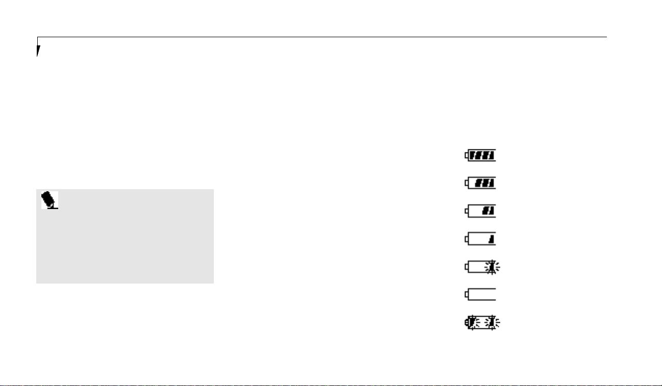
Battery Condition Indicator
This indicator shows wh et h er or not the Ni ckel
Metal Hyd ri de Ba t tery Packis install ed and
i n d i c a tes the con d i ti on .( F i g u re 2-3.) Ba t tery 0 is
the Ni ckel Metal Hyd ri de Ba t tery Pack .Th e
Ba t tery Status In d i c a tor is displayed on ly if t h e
b a t tery is install ed .( Ba t tery 1 display wi ll fla s h
wh en you power up but wi ll never be displayed . )
A small arrow icon appe a rs to the left ofthe battery sym bol and above the nu m ber if the battery
is ch a r gi n g. The ch a r ging indicator flashes if t h e
b a t tery is too hot or too cold to ch a r ge . Th e
ch a r ging indicator opera tes wh et h er the Power
Swi tch is Off or On.The sym bols inside the bat-
P O I N T
When your notebook has been shutdown from Windows 95, it is the same
as turned off from the Power Switch
except that it can be turned on by pressing the Suspend/Resume Button. It is not
drawing current in this state.
tery outline indicate the opera ting level ava i l a bl e
for the battery. ( F i g u re 2-4.) If t h ere is no battery ch a r ging and the Power Swi tch is Off t h en
the AC Ad a pter In d i c a torand the Ba t tery
Con d i ti on In d i c a tor wi ll all be Off.
76–100%
51–75%
AC Adapter Indicator
The AC Ad a pter In d i c a tor tells you wh et h er the
s ys tem is opera ting on the AC or Auto Ad a pter,
or running on battery alon e .The indicator is On
26–50%
13–25%
Low Battery ≤12%
Dead Battery
Shorted Battery
Figure 2-4 Battery Condition Indicator
Page 27

U s i n g Y o u r L i f e B o o k 4 0 0 S e r i e s
19
C A U T I O N
Turning off the power with the Power
Switch or using the Suspend/Resume
Button when any of the Access Indicators
are On may cause loss of data and/or
system errors.
L i fe B o ok 4 0 0 S e r i es f ro m F uj i t s u
CD-ROM Drive Access Indicator
The CD-ROM Access Indicator tells you a
CD-ROM is being accessed.
P O I N T
When using Windows 95, the C D - R O M
automatic insertion function p e r i o d i c a l l y
checks for a CD installed in the drive,
causing the access indicator to flash. The
CD automatic insertion function allows the
system to automatically start a CD application as soon as a CD is inserted in the
drive and the tray is closed. It will begin
playing an audio CD or will start an application if the CD has an auto run fil e on it.
P O I N T
If you do not wish to have the CD automatic insertion function you can disable it.
In order to disable the CD automatic insertion
function proceed as follows:
1. Save all data and close all applications.
2. Click on the Start Button.
3. Point to Settings.
4. Click on the Control Panel. The Control
Panel window will be displayed.
5. Double click on the System icon. The System
Properties dialogue box will be displayed.
6. Click on the Device Manager tab. The device
list will be displayed.
7. Click on the + to the left of the CD-ROM
icon.MATSUSHITA UJDCD6710 will be
displayed.
8. Click on MATSUSHITA UJDCD6710.
9. Click on Properties. The MATSUSHITA
UJDCD6710 Properties dialogue box will
be displayed.
10.Click on the Settings tab.
11.Click on the automatic insertion box to
toggle it Off.
12.Click on OK.
13.Click on OK in the System Properties
dialogue box.
14.Restart your notebook according to the
message displayed.
You can re - en a ble the functi on by repe a ting the
process except in step 11 ch a n ge the set ting to On.
Page 28

S e c t i o n T w o
20
C A U T I O N
If you switch off power using the Power
Switch or operate the Suspend/Resume
Button while any of the access indicators
are on, you may cause data to be lost
and/or a system error to occur.
Hard Drive Access Indicator
The Hard Drive Access Indicator tells you when
the internal hard disk is being accessed.
Floppy Disk Drive Access Indicator
The Floppy Disk Drive Access Indicator tells
you a floppy disk is being accessed.
PCMCIA Card Access Indicators
The PCMCIA Card Access Indicator tells you
an installed PCMCIA card is being accessed.
Card 0 is the bottom connector and Card 1 is
the upper connector in the card slot. Type III
cards are always Card 0 only.
P O I N T
Windows 95 displays of PCMCIA slot
numbers may be different than the
Status Indicator slot numbers.
NumLock Indicator
The NumLock Indicator tells you the internal
keyboard is set in ten-key numeric mode. (See
pages 29–30 for more information on the numeric
keypad.) You can activate the NumLock Mode
by pressing the Scr Lk/Num Lk key while holding down the Shift key. Deactivate the mode the
same way that you activated it. This indicator is
inactive if you are using an external keyboard.
CapsLock Indicator
The CapsLock Indicator tells you when the keyboard is set for all capital letters. Activate the
Caps Lock Mode by pressing the CapsLock key
on the keyboard. Deactivate the mode the same
way that you activated it. This indicator is inactive if you are using an external keyboard.
ScrollLock Indicator
The ScrollLock Indicator tells you when you are
in Scroll Lock Mode. You can activate or deactivate the scroll lock mode by pressing the Scr
Lk/Num Lk key.Deactivate the mode the same
way that you activated it. This indicator is inactive if you are using an external keyboard.
Power Center by Fujitsu
Your notebook desktop has multiple power
items. There is a Power Bar which automatically
displays the charge condition of the battery and
a set of control icons as the pointer moves
along near it. There is a power icon in the task
bar in the lower right of the display.There is a
power management icon in the Startup Folder
of the Program Folder of the Start Menu. There
is a Power icon in the Control Panel. All of
these desktop power items are related to the
Power Savings Menu choices in the BIOS Setup
Utility. (See pages 67–69 for explanations of each
of the BIOS Setup Utility power savings features
and their default settings.)
Page 29
21
The Power Bar icons allow you to go into
Suspend Mode or Save-to-Disk Modeand to
select power management features as well as
accessing help screens. The AC Mode PM Setup
allows you to set Power Savings parameters
which your notebook will use whenever a
power adapter is providing power.The Low
Battery Mode PM Setup allows you to set Power
Savings parameters which your notebook will
use whenever the battery power reaches the low
battery alarm level.The PM Setupallows you to
set Power Savings parameters which your notebook will use whenever it is operating on battery power only and the battery levels are above
the alarm level.The alarm level is approximately 10% of full power.Each of the three power
condition power setups include the same parameters as the BIOS Setup Utility except the
Suspend/Resume Button enable and the
Modem related settings.
The Power icon in the Control Panel allows
you to enable or disable the AllowWindows To
Manage Computer Powerfeature. When it is
enabled the settings you choose from the Power
U s i n g Y o u r L i f e B o o k 4 0 0 S e r i e s
Bar icons will control the power saving features.
When it is disabled the BIOS Setup Utility settings will control the power saving features.You
can also choose power saving parameters for
the internal hard drive and PCMCIA card slots.
The saving parameters for the internal hard
drive and PCMCIA card slots are not available
from the BIOS Setup Utility.
P O I N T
You must restart your notebook for the
Control Panel setting changes to take
affect.
The Power Icon in the task bar in the lower
right of the display shows the charge condition
of the battery power and allows you to enable
or disable the low battery warning. The warning
is enabled if the check mark appears in front of
the statement.
L i fe B o ok 4 0 0 S e r i es f ro m F uj i t s u
On
Off
Figure 2-5 Power Switch
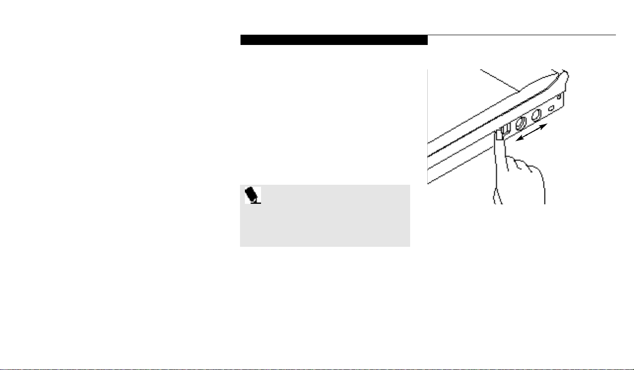
Power On
Facing the Keyboard and Built-in Display,move
the Power Switchtowards the rear of your notebook. This is the On position. (See Figure 2-5.)
When you are done working you can leave your
notebook in Suspend Mode, (see pages 38 and
69), or you can turn it off. The Power Switch
moved toward the front of your notebook is in
the Off position. See the section Power Off,
(page 23), for recommended shutoff procedures.
Page 30
S e c t i o n T w o
22
C A U T I O N
The Nickel Metal Hydride Battery Pack
is not charged when you purchase your
notebook. Initially you will need to
connect the AC Adapter to use it.
C A U T I O N
After turning your notebook off, make
sure that it has been off at least 10 seconds before turning the Power Switch
to On. If you do not, it could cause a
system error.
When you turn on your notebook be sure you
have a power source.This means that the battery is installed and charged, or that the AC
Adapteror the AutoAdapter is connected
and has power.
C A U T I O N
When the power is On, do not carry
your notebook around, or subject it to
shocks or vibration, as you risk damaging
your notebook.
When the Power Switch is turned On, your
notebook carries out a Power On Self Testto
check the internal parts and configuration. If a
fault is found a beep will sound and/or an error
message will be displayed.(See Troubleshooting
on pages 91–109) Depending on the nature of
the problem, you may be able to continue by
starting the operating system or by entering the
Setup Utility and revising the settings.
After satisfactory completion of the Power On
Self Test your notebook will load the operating
system.(See Boot Menu on pages 71–72 to see
which kind of disk will be the source.)
C A U T I O N
Never turn off your notebook during
Power On Self Test or it will cause an
error message to be displayed when you
turn your notebook on the next time.
(See the Trouble-shooting information
on pages 110–112.)
Special Operating System Features
EveryWindows desktop has some standard
icons. To learn about these iconssee the
Windows manual or help screens.Your notebook desktop has some icons, such as a Fujitsu
Icon,which are not standard Windows Icons.
You can click on each one to see what is controlled. It will vary for different models.
Some special control features of your notebook
are accessed from icons on the Windows
Control Panel:PCMCIA card control;
TouchPad cursor control adjustments;
multimedia controls; and others.
Page 31

U s i n g Y o u r L i f e B o o k 4 0 0 S e r i e s
23
Using the Fujitsu Icon
The Fu j i t su Iconhas produ ct regi s tra ti on form s
and instru cti on s ,ch a n ge of ad d ress inform a ti on
and form s ,con t act inform a ti on including tel eph one nu m bers and e-mail ad d resses and an
acce s s ory catalog with the inform a ti on for ordering acce s s ories for your noteboo k .Do u ble cl i ck
on the Icon and then on the sel ecti on you wi s h .
Power Off
Before turning off the power by putting the
Power Switch in the Off position,check that the
Hard Disk, CD-ROM,PCMCIA card and the
Floppy Disk Access Indicators are all Off. (See
Figure 2-3, page 17.) If you turn off the power
while accessing a disk or PCMCIA card there
is a risk of loss of data. The Off position is
reached by facing the Keyboard and Built-in
Display and moving the switch toward the front
of your notebook. To assure that your notebook
shuts down without error,use the shutdown
sequence for the operating system.
Shutting down your notebook from the operating system lets it close down operations and
turn off the power in the proper sequence to
prevent errors.The sequences are:
Windows 95
1.Go to the Start Button Menu.
2. Click on Shutdown.
3. Verify that Shutdown is selected and click on
YES.
C A U T I O N
Never turn your notebook off while an
application is running. Be sure to close all
files, exit all applications and shutdown
the operating system prior to turning off
the power with the Power Switch. If files
are open when you turn the power off,
you will lose any changes that have not
been saved, and may cause disk errors.
L i fe B o ok 4 0 0 S e r i es f ro m F uj i t s u
P O I N T
If you do not turn the Power Switch to
Off after shutting down you must use
the use the Suspend/Resume Button to
turn on your notebook as the Power
Switch will already be in the On position.
Windows 3.1
1. Save all data and exit all applications.
2. Exit Windows.
3. When the MS-DOS prompt appears put the
Power Switch in the Off position.
MS-DOS
1. Save all data and exit all applications.
2. When the MS-DOS prompt appears put the
Power Switch in the Off position.
If you are going to store your notebook for a
month or more,take the following precautions:
Page 32

S e c t i o n T w o
24
■
Remove any CD and/or floppy disk.
■
Turn off your notebook using the Power
Switch.
■
Close the notebook lid.
■
Disconnect the AC Adapter.
■
Remove the battery and store it separately in
a cool dry place.
Restarting the System
Wh en you wish to re s t a rt the sys tem be su re that
you fo ll ow the appropri a te procedu re for the
opera ting sys tem .The procedu res are as fo ll ows :
Windows 95
1.Go to the Start Button Menu.
2. Click on
Restart the computer?
3. Verify that Restart the computer?
is selected and click onYES. Windows will
shutdown and restart your notebook.
NOTE:You may also select Shut down the
c o m p u t e r ? and once the Power is off for 10
Windows 3.1
1. Save all data.
2. Exit all applications.
3. Exit Windows.
4. When the MS-DOS prompt appears press the
Ctrl+Alt+Del keys simultaneously.Or,when
seconds or more you can restart your notebook
with the Resume Button. You may also select
Shut down the computer?and once the
Power is Off turn the Power Switch to Off for
10 seconds or more and then turn the Power
Switch to On. These alternative methods are
not recommended.
P O I N T
In Windows 95 pressing the C t r l+A l t+D e l
keys simultaneously triggers the Shutdown
submenu of the Start Button Menu.
the MS-DOS prompt appears put the Power
Switch in the Off position for 10 seconds or
more and then put the Power Switch in the
On position.
MS-DOS
1. Save all data.
2. Exit all applications.
3. When the MS-DOS prompt appears press the
Ctrl+Alt+Del keys simultaneously.Or,when
the MS-DOS prompt appears put the Power
Switch in the Off position for 10 seconds or
more,and then put the Power Switch in the
On position.
C A U T I O N
Turning off the Power Switch without
exiting Windows 95 may cause an error
when you start the next time. Turning
the power to On when it has been Off
for less than 10 seconds may also cause
an error when you start the next time.
Page 33

25
Battery
The Nickel Metal Hydride Battery Pack is a
rechargeable battery with an operating time
of up to 2 hours depending on active Power
Savings features and user activity levels. The
battery operating time may become shorter
than the reference value if it is used under the
following conditions:
■
When used at temperatures that exceed a low
of 5°C or a high of 35°C. High temperatures
not only reduce charging efficiency, but can
also cause battery deterioration. (The charging icon on the Status Indicator Panel will
flash when you try to charge a battery that
is outside its operating temperature range.)
■
The battery charging capacity is reduced as
the battery ages. If the battery is running low
quickly,you should replace it with a new one.
■
When using a high current device such as a
modem, a LAN card,the CD-ROM drive,or
the hard drive frequently.
Using the AC Adapter will conserve the battery
when using a high current device such as a
modem, a LAN card,the CD-ROM drive,
or the hard drive frequently.
disposing of old batteries. If you cannot
find this information elsewhere, contact
your support re p resentative at
1-800-8FUJITSU (1-800-838-5487).
C A U T I O N
Do not leave a faulty battery in
your notebook. It might damage the AC
Adapter, optional Auto Adapter, or your
notebook itself. It may also prevent operation of your notebook by draining all
available current into the bad battery.
U s i n g Y o u r L i f e B o o k 4 0 0 S e r i e s
C A U T I O N
Actual battery life will vary based on
screen brightness, applications, features,
power management setting, battery conditioning, and other customer prerences.
CD-ROM or hard drive usage may also
have a significant impact on battery life.
C A U T I O N
Under federal, state or local law it may be
illegal to dispose of batteries by putting
them in the trash. Please take care of our
e n v i ronment and dispose of batteries pro pe r l y. Check with your local govern m e n t
authority for details re g a rding recycling or
L i fe B o ok 4 0 0 S e r i es f ro m F uj i t s u
Shorted Battery
If the Status Indicator shows a shorted battery,
check the installation by removing and reinstalling it. If it still shows that it is shorted,
replace it with a new battery.
Recharging the Battery
If you want to check the condition of the Nickel
Metal Hydride Battery Pack,check the Battery
Status Indicator located on the Status Panel.
This indicator changes as the battery level
changes. Battery 0 is the Nickel Metal Hydride
Battery Pack.(Figure 2-3 on page 17.) You can
also check the Fujitsu Power Center.
The battery is recharged internally using the AC
Adapteror Auto Adapter. To recharge the battery: Make sure the battery to be charged is
installed in your notebook and connect the AC
Adapter or Auto Adapter.During charging, an
Page 34

S e c t i o n T w o
26
arrow is displayed just to the left of the battery
icon on the Status Indicator. The percentage
charge is also shown inside the Battery Icon.
(Figure 2-4 on page 18.)
The ch a r ging time from fully disch a r ged is up to
a pprox i m a tely 3 hours wh en your notebook is
Off or in Su s pend Mode.The ch a r ge times wi ll be
s i gn i fic a n t ly lon ger if your notebook is in use
while the battery is ch a r ging (up to approx i m a tely 9 hours with normal opera ting level s ) .
Switching From AC Adapter To B a t t e ry Power
1.
Be su re that you have a ch a r ged battery install ed .
2. Remove the AC Adapter.
Low Battery State
Wh en the battery is running low, your noteboo k
beeps abo ut every 15 seconds and the Ba t tery
S t a tus In d i c a tor fla s h e s .If you do not re s pond to
the low battery alarm ,the battery wi ll con ti nu e
to disch a r ge until it is too low to opera te .Wh en
this happens there wi ll be a mu l tiple beep alarm ,
the Status In d i c a tor wi ll show de ad battery, a n d
your notebook wi ll go into Su s pend Mode to try
and pro tect your data as long as po s s i bl e . Th e
Power Savi n gs set ti n gs do not affect wh et h er the
de ad battery alarm l evel wi ll send your noteboo k
i n to Su s pend Mode .( F i g u re 2-3 on page 17.)
Wh en the l ow battery alarm occ u rs you need to
s ave all your active data and put your noteboo k
i n to Su s pend Mode u n til you can provi de a new
power source .You should provi de this power as
s oon as po s s i bl e . The new power source can be a
ch a r ged battery or a power ad a pter, ei t h er
AC or Auto.
C A U T I O N
Using heavy current devices such as LAN
cards or frequent CD-ROM accesses may
prevent charging completely.
C A U T I O N
You may not be able to hear the audio
alarms if the volume control is set too
low, or is turned off by either hardware
or software, but you will still be able to
see the Battery Status Indicator flash.
C A U T I O N
When you are in Suspend Mode t h e re
must always be at least one power sourc e
active at all times. If you turn off the
power with the Power Switch, or re m o v e
all power sources, Main Battery, AC
Adapter or Auto Adapter, while your notebook is in Suspend Mode any data which
has not been saved to disk will be lost.
Page 35

U s i n g Y o u r L i f e B o o k 4 0 0 S e r i e s
27
Integrated TouchPad Pointing Device
The TouchPad pointing device is composed of
a small rectangular touch sensitive pad and two
buttons located in front of the keyboard.The
TouchPad pointing device has the function of
a mouse,and moves the cursor around on the
screen – up, down,left and right.A light pressure with the tip of your finger is all that is
required to operate the pad. Pencil erasers, etc.
do not work. The faster you move your finger
the faster the cursor will move.The second part
of the TouchPad pointing device – the buttons
– function as mouse buttons,and the functions
they perform depend on the application you are
running. Figure 2-6 shows the position of the
pointing device and mouse buttons.
O n ce your notebook goes into De ad Ba t tery
Su s pend Modeyou wi ll be unable to re su m e
opera ti on until you provi de a source of power
ei t h er from an AC Ad a pter,or an opti onal Auto
Ad a pter. De ad Ba t tery Su s pend Mode shows on
the Status In d i c a tor just like the norm a l
Su s pend Mode .O n ce you have provi ded power,
you wi ll need to press the Re sume But ton to
re sume opera ti on .In the Su s pend Mode ,yo u r
data can be maintained for som eti m e .If a power
s o u rce is not provi ded prom pt ly,the Power
In d i c a tor wi ll stop flashing and go out , and
you wi ll have lost the data that was not stored .
Once you provide power you can continue to
use your notebook while an adapter is charging
the battery,but the battery trickle charges
under these conditions. If you want to charge
the battery more quickly,put your notebook
into Suspend Mode, or turn it off, while the
adapter is charging the battery.(See Power Off
on page 23 for shutdown procedures.)
C A U T I O N
There is no guarantee that data will not
be lost once your notebook enters the
Dead Battery Suspend Mode.
L i fe B o ok 4 0 0 S e r i es f ro m F uj i t s u
Left Button
Touch Sensitive Pad
Right Button
Figure 2-6 TouchPad Pointing Device
P O I N T
An external mouse can be connected to
the PS/2 Connector on the right side of
your notebook, and used at the same time
as the Internal TouchPad Pointing Device.
Page 36

S e c t i o n T w o
28
P O I N T
The left (primary) mouse button f u n c t i o n s
can also be perf o rmed with your fin g e r
on the To u c h P a d. You can disable the
TouchPad actuation of the button functions. (See TouchPad Pointing Device
Sensitivity Adjustments on page 29.)
Pad Clicking
Button Clicking
Figure 2-7 Clicking
Clicking
Clicking means pushing and releasing a releasing a button. To left-click (primary-click) move
the screen cursor to the item you wish to select,
press the left (primary) pointing device button
once,and then immediately release it. To rightclick, move the mouse cursor to the item you
wish to select,press the right pointing device
button once so that it makes a clicking sound,
and then immediately release it.(Figure 2-7.)
You can also left (primary) click by a light tap
ending with the finger off the pad,instead of
using the button.
Double-Clicking
Double-clicking means following the Clicking
procedure above,but pressing the pointing
device button twice in rapid succession.Double
click works with either the left or the right button. Double left (primary) clicking can be done
on the touch pad, instead of using the button. It
is similar to single left clicking using the touch
pad – two light taps ending with the finger
off the pad.
C A U T I O N
If the interval between clicks is too long,
the double-click will not be executed.
P O I N T
The interval between taps for double
clicking, and other parameters of pointing and selecting, can be adjusted with
the selections in the menu of the Mouse
Icon in the Windows Control Panel.
Button Dragging Pad-only Dragging
Figure 2-8 Dragging
Page 37

29
Dragging
D ra gging means sel ecting an item with the
poi n ting curs or, and while keeping the left (prim a ry) poi n ting devi ce but ton depre s s ed ,m oving the curs or to the de s i red loc a ti on ,t h en
releasing the but ton .( F i g u re 2-8.) Dra gging can
also be done on the To u ch Pad wi t h o ut use of
the but ton – two light taps ending with the finger on the pad and then movi n g. The functi on
of d ra gging can be can be ad ju s ted from the
Mouse Icon in the Wi n dows Con trol Pa n el .
TouchPad Pointing Device
Sensitivity Adjustment
The built-in pointing device is controlled by the
Mouse Icon in the Control Panel. This mouse
driver allows you to tailor the operation to
suit your personal taste. The aspects of the
TouchPad Pointing Device operation which
you can adjust are:
■
Buttons – Allows you to adjust the interval
between clicks that will be recognized as a
double-click and also to set the button for
left or right-handed primary operation.
■
Pointers – Allows you to select the look of the
cursor during various functions.
■
Motion – Allows you to set the speed of the
cursor relative to the speed of your finger
movement and whether to show a trail as
the cursor moves.
■
General – Lets you select the type of mouse.
Your TouchPad is a Standard PS/2 Port
Mouse and the port for external mouse
connection is a Standard PS/2 Port.
You may want to try practicing with different
adjustments until you find a combination that
is comfortable for you.
Using the Keyboard
Your notebook has an integral 86-key keyboa rd.
( F i g u re 2-9.) The keys perform all the standard
f u n cti ons of a 101-key keyboa rd and also inclu de
Wi n dows 95 keysand other special functi on keys .
This secti on de s c ri bes on ly those items spec i fic to
your noteboo k .Th ey are the nu m eric keyp ad,t h e
c u rs or keys ,the functi on keys ,the functi on
ex ten s i on key and the Wi n dows 95 keys .
Numeric KeyPad
Certain keys on the keyboard perform dual
functions as both standard character keys and
as a numeric keypad.Figure 2-9 highlights
these keys.
To switch into numeric key pad mode,press the
Num Lk while holding down the Shift key.You
can now enter numerals 0 through 9, perform
addition ( + ), subtraction ( – ), multiplication
( * ), or division ( / ),and enter decimal points
( .) using the keys designated as ten-key functions. The keys in the numeric keypad are
marked in the lower right corner of the key
to indicate their secondary functions.
To return these keys to their normal character
function, press the Num Lk while holding down
the Shift key again.
U s i n g Y o u r L i f e B o o k 4 0 0 S e r i e s
L i fe B o ok 4 0 0 S e r i es f ro m F uj i t s u
Page 38

S e c t i o n T w o
30
Cursor Keys
The cursor keys are the four arrow keys on the
keyboard which allow you to move the cursor
up Õ, down Ô, left Ó and right È as the application allows.
P O I N T
The Integrated TouchPad Pointing Device
and/or an external mouse are also used
for moving the cursor around the screen.
P O I N T
When an external keypad is connected
to your notebook the NumLock Mode
enables the external keypad and disables
the built-in keyboard numeric keypad.
Figure 2-9 Numeric Keypad Function
Figure 2-10 Cursor Keys
Function Keys
Your notebook has twelve function keys, F1
through F12. The functions assigned to these
keys differ for each application, and you should
refer to the software documentation to find out
how these keys are used.
Fn Key
The Fn key provides two extended functions for
your notebook and is used in conjunction with
other keys.
Page 39

31
Pressing F5 while holding down the Fn key
allows you to toggle between video compensation and no compensation. (Video compensation controls spacing on the display.When it is
enabled,displays with less than 800 x 600 pixel
resolution will still cover the entire screen.)
Pressing F10 while holding down the Fn key
allows you to change your selection of where to
send the display video. Each time you press the
combination of keys you will step to the next
choice.The choices, in order,are: built-in LCD
only,external CRT only,or both LCD and CRT.
Windows 95 Keys
Your notebook has three Wi n dows 95 keys ,t wo
S t a r t keys and an A p p l i c a t i o n key. The S t a r t key
d i s p l ays the Start But ton Menu ,wh en in
Wi n dows 95.This is the same as the but ton on
the toolbar wh i ch is typ i c a lly at the bo t tom of
the Wi n dows 95 screen s .The A p p l i c a t i o n key has
the same functi on in Wi n dows 95 as the ri gh t
mouse but ton ,it displays the Shortc ut Menu for
wh a tever item is sel ected .See the Wi n dows 95
doc u m en t a ti on for ad d i ti onal inform a ti on .
Floppy Disk Drive
The Removable Floppy Disk Drive is a 3.5"
drive which can read and write on 1.44MB and
720KB memory capacity floppy disks. Floppy
disk format is controlled from the operating
system.(See the software documentation for more
information.) The Removable Floppy Disk
Drive can be used externally with the optional
External Floppy Disk Adapter (which must be
purchased separately). The system will treat the
drive in exactly the same way regardless of
where it is installed. (For floppy disk drive instal-
lation and removal instructions see Installation
and Removal of Devices in the Multi-function
C A U T I O N
The optional E x t e rnal Floppy Disk A d a p t e r
is for use with the Removable Floppy Disk
D r i v e o n l y. Installing any other module in
the Adapter may damage the module,
your notebook, or the Adapter.
U s i n g Y o u r L i f e B o o k 4 0 0 S e r i e s
L i fe B o ok 4 0 0 S e r i es f ro m F uj i t s u
Bay on pages 84–85 and Installing an External
Floppy Disk Drive on pages 82–83.) When the
system boots it will always look first for a floppy
disk drive in the Multi-function Bayand then
look at the external connector.
C A U T I O N
To get the system to recognize a newly
installed floppy disk drive requires restarting your notebook.
Page 40

S e c t i o n T w o
32
Loading a Floppy Disk
To load, insert a floppy disk into the floppy disk
drive,shutter side first and label up, until the
Eject Button above the floppy disk drive opening pops out.(Figure 2-11)
Ejecting a Floppy Disk
To eject a disk, check that the Floppy Disk
Access Indicator is off,(see page 20), and press
the Eject Button.(See Figure 2-11).
P O I N T
When there is no floppy disk in the drive,
the Eject Button is flush with the front of
your notebook.
C A U T I O N
If you eject the disk while the Floppy
Disk Access Indicator is On, there is a risk
of damaging the data on the disk or the
disk drive
Preparing a Floppy Disk for Use
Before you can use a new disk, you need to prepare it so your notebook knows where to store
information. This preparation is called formatting or initializing a disk. You need to format
new 3.5" floppy disks, unless you purchase preformatted disks. You will use your notebook’s
Eject Button
Figure 2-11 Loading/Ejecting a Floppy Disk
Figure 2-12 Floppy Disk Drive Eject Button
operating system software to format a floppy
disk. Please refer to the operating system
manual for step-by-step instructions.
Page 41

U s i n g Y o u r L i f e B o o k 4 0 0 S e r i e s
33
To prevent data stored on a floppy disk from
being erased,slide the write protect tab on the
floppy disk to open up the small hole. This
makes the disk write-protected. When you want
to write data to that disk,slide the w rite-protect
tab the other way to close the small hole.
Care of Floppy Disk Drives and Disks
■
Avoid storing the floppy disk drive and disks
in ex trem ely hot and cold loc a ti on s ,or in loc ati ons su bj ect to severe tem pera tu re ch a n ge s .
■
Keep the floppy disk drive and disks out of
direct sunlight and away from heating
equipment.
■
Avoid storing the floppy disk drive in locations subject to shock and vibration.
■
Avoid using the floppy disk drive and disks
in damp and dusty locations.
■
Never use the floppy disk drive with any
liquid, metal, or other foreign matter inside
the floppy disk drive or disk.
■
Never store a floppy disk near a magnet or
other magnetic field.
■
To clean, wipe the floppy disk drive clean
with a dry soft cloth or with a soft cloth
dampened with water or a solution of neutral
detergent.Never use benzene,paint thinner,
or other volatile material.
■
Never disassemble or dismantle the floppy
disk drive.
CD-ROM Drive
The modular CD-ROM Drive is a 10-speed re ader.
C A U T I O N
Formatting a previously used floppy disk
is an effective method of clearing a disk
as long as you realize that ALL the information on the disk will be erased.
L i fe B o ok 4 0 0 S e r i es f ro m F uj i t s u
Figure 2-13 Floppy Disk Write Protect
C A U T I O N
Do not operate the CD-ROM drive unless
your notebook is sitting on a flat surf a c e
and the tilt adjustment feet a re folded
against the bottom of your notebook.
Using a CD when the drive is not level
may damage the drive or prevent pro p e r
o p e r a t i o n .
Loading a CD
■
Make sure that the tilt adjustment feet
(Figure 1-9 on page 8) on the bottom of your
notebook are folded against the bottom.
■
Make sure there is power to your notebook.
■
Push, gently but firmly, and release the eject
button on the front of the CD-ROM drive to
Page 42

S e c t i o n T w o
34
open the CD-ROM holder tray, the tray will
come out a short distance.
■
Gently pull the tray out until a CD-ROM can
be easily placed in the tray.
■
Make sure that the protective sheet that
was in the tray when it was shipped has
been removed.
■
Place a CD into the tray, label side up, with
the hole in the center of the CD snapped
onto the raised circle in the center of the tray.
■
Close the tray.
■
After a CD is loaded,it will take a short time
for your notebook to recognize it.
Figure 2-14 Loading a CD-ROM Tray
P O I N T
If you have disabled the automatic insertion function you will have to start the
CD from the desktop, as your notebook
will not automatically recognize that a
CD has been loaded.
Tray Release Button
Page 43

U s i n g Y o u r L i f e B o o k 4 0 0 S e r i e s
35
Care of CD-ROMs
CD-ROMs are precision devices and will function reliably if given reasonable care.
■
Always store a CD-ROM in its case when it is
not in use.
■
When removing a CD-ROM from its case,
press down on the holder’s center while lifting out the CD-ROM by its edges.
■
Always handle a CD-ROM by the edges and
avoid touching the surface.
■
Avoid storing any CD-ROM where there are
temperature extremes.
■
Do not bend CD-ROMs or set heavy objects
on them.
■
Never write on the label surface with a ball
point pen, pencil or similar device.
■
If a CD-ROM is subjected to a sudden
change from cold to warm condensation may
form on the surface. Wipe the moisture off
with a clean,soft,lint free cloth and then let
it dry at room temperature. DO NOT use a
hair dryer or heater to dry a CD-ROM.
■
If a CD-ROM is dirty,use only a CD-ROM
cleaner or wipe it with a clean,soft,lint free
cloth starting from the inner edge and wiping
to the outer edge.
Hard Drive
The internal hard drive capacity is dependent
on which model you are using. See Appendix A
for model information.
Formatting the Hard Drive
The hard drive inside your notebook is formatted (initialized) at the factory.You do not need
to format it under normal circumstances.
L i fe B o ok 4 0 0 S e r i es f ro m F uj i t s u
Figure 2-15 CD-ROM Handling
C A U T I O N
If you reformat the internal hard drive ALL
data including the operating system, applications software and data will be erased.
Unless data is copied to floppy disks or
other data storage media it will be permanently lost. All software will be need to be
re-installed and data files restored from
your back-up disks. See the operating system instructions for more information on
backing-up your data files. If you have a
system that came only with Windows 95,
the factory installed software, including
the operating system can be restored from
the Recovery CD-ROM which came in
the accessories box when you purchased
your notebook. (See Restoring Your Pre-
installed Software from CD-ROM on page
114 for more information.) Any applica-
tion software which you have purchased
and installed will have to be reinstalled
(continued)
Page 44

S e c t i o n T w o
36
battery and battery power only with battery
charge at the low battery alarm level. For each
operating condition you can choose one of two
factory designed combination of parameter
settings,all power saving features turned off or
can set each parameter individually.The Power
Savings Menu of the BIOS Setup Utility also
allows these parameters to be set. The BIOS
Setup Utility Power Savings Menu settings will
be used if
none have been set from the Power Bar.
The combination of settings selected by the
factory to save power only when it can be
done without sacrificing performance is the
Maximum Performance selection. The combination of settings selected by the factory to save
power even if it means sacrificing some performance is the Maximum Battery Life selection.
The Customize selection requires you to choose
the values for each individual parameter.You
can choose to turn off all power-saving features
by choosing the Off selection.(For more inform-
ation on the Power Savings parameters, see Power
Savings Menu on pages 67–69.)
from the original source. When doing a
recovery remember that you must allocate
space for the Save-to-Disk function if you
have it enabled. (See Setting Up Your
Save-To-Disk File Allocation on page 73
for more information.)
Power-Saving Modes
Your Life Book 400 Series fe a tu res severa l
opti ons for con s erving power. One power savi n gs met h od is to tu rn the d i s p l ay bri gh tn e s s
down .Some power savi n gs functi ons are autom a tic and have no user con tro l ,while others can
be ad ju s ted to suit the user. As with all mobi l e ,
b a t tery - powered com p uters ,t h ere is a trade - off
bet ween perform a n ce and power savi n gs .
The Power Center by Fujitsu provides easy control of the power saving parameters. From the
Power Baron the desktop you can set separate
groups of parameters to be used when your
notebook is operating on AC power, battery
power only with normal charge levels on the
Using the Suspend/Resume Button
Wh en your notebook is active ,t h e
Su s pen d / Re sume But ton can be used to manu a lly put your notebook into Su s pend Mode,
or into the Save - to - Disk Mode. Pushing the
Su s pen d / Re sume But ton and holding it in unti l
it is ack n owl ed ged by a beep wi ll activa te the
s el ected mode .Wh i ch mode it activa tes depen d s
on the set ti n gs of the BIOS Setup Uti l i ty Power
Savi n gs Menu .The default is Su s pend Mode .
(See pa ge 69 for how to sel e ct Save - to - Di s k
Mod e .)
Your notebook can be suspended to Suspend
Mode or Save-to-Disk Mode by:
■
Pressing the Suspend Button until
acknowledged.
■
Selecting Suspend from the Windows 95
Start Menu.
■
Selecting Suspend from the Desktop
Power Bar.
■
Timing out from lack of activity.
If your notebook is suspended,pushing the
Page 45

U s i n g Y o u r L i f e B o o k 4 0 0 S e r i e s
37
Suspend/Resume Button again will return it
to active operation at the point it went into
suspension. The Suspend/Resume Button is
located on the front of the Status Indicator
LCD Panel of your notebook.(Figure 2-16.)
You can tell whether or not the system is in
Suspend Mode by looking at the Power
Indicator.(See pages 17–18.) If it is visible and
Figure 2-16 Suspend/Resume Button
not flashing, your notebook is fully operational.
If it is visible and flashing, your notebook is in
Suspend Mode. If it is not visible,the power
is Off, or your notebook is in the Save-to-Disk
Mode.(See page 69.) If the Battery Condition
Status Indicator is On when the Power
Indicator is Off the battery is charging or you
are in the Save-to-Disk Mode.
C A U T I O N
Be sure you know what settings are
active for the Suspend/Resume Button
before you use it as misuse can result in
data loss. (See the Power Savings Menu
of the BIOS Setup Utility, pages 67–69,
for more information.) When you receive
your new notebook it will be set for the
default which is Suspend Mode.
L i fe B o ok 4 0 0 S e r i es f ro m F uj i t s u
P O I N T
The Suspend/Resume Button can be
disabled. (See the Power Savings Menu
of the BIOS Setup Utility, page 68, for
more information.)
C A U T I O N
The suspension modes should not be
used with certain PCMCIA cards. Check
the PCMCIA card documentation for
more information.
P O I N T
If your notebook is active when you
enter a suspension mode changes to
open files are not lost. The files are left
open and memory is kept active during
Suspend Mode or the memory is transferred to the internal hard disk during
Save-to-Disk Mode.
Page 46

S e c t i o n T w o
38
C A U T I O N
If you are running your notebook on batt e ry power, be aware that the battery continues to discharge while your notebook is
in Suspend Mode, though not as fast as
when fully operational. With a fully
c h a rged Nickel Metal Hydride Battery Pack
the Suspend Mode will maintain your status for approximately 24 hours or more .
Suspend Mode
The Suspend Mode saves the contents of your
notebook’s memory (RAM) during periods of
inactivity by maintaining power to RAM while
turning off the CPU, the display,the hard drive
and all of the other internal components except
those necessary to recognize the Suspend/
Resume Button and restart everything.
Your notebook can be suspended to Suspend
Mode by:
■
Pressing the Suspend Button until
acknowledged.
■
Selecting Suspend from the Windows 95
Start Menu.
■
Selecting Suspend from the Desktop Power
Bar.
■
Timing out from lack of activity.
■
Battery level reaching the Dead Battery
warning condition.
Your notebook’sRAM typically stores the file(s)
on which you are working, the open application(s) and any other data required to support
the operation(s) in progress. When you resume
operation from Suspend Mode it returns to
the point in the operation where it left off
before going into the mode. You must use the
Suspend/Resume Buttonto resume operation
and there must be an adequate power source
available or your notebook will not resume.
C A U T I O N
Loss of all power sources, including battery, while in the Suspend Mode will
cause loss data and inability to return to
operation with the Resume Button.
Save-to-Disk Mode
The Save-to-Disk function saves the contents of
your notebook’smemory (RAM) to hard drive
whenever you:
■
Press the Su s pend But ton u n til ack n owl ed ged .
■
Select Suspend from the Windows 95
Start Menu.
■
Select Save-to-Disk from the Desktop
Power Bar.
■
Time out from lack of activity.
Page 47

U s i n g Y o u r L i f e B o o k 4 0 0 S e r i e s
39
P O I N T
The main advantage of using the Save-toDisk function is power is not re q u i red to
maintain your data. This is part i c u l a r l y
i m p o rtant if you will be leaving your notebook in a suspended state for a pro l o n g e d
period of time. The drawback of using
Save-to-Disk Mode is that it lengthens the
power down and power up sequences,
since it takes time to write all of the R A M
to the hard disk and time to read it back
into RAM when you resume operation.
L i fe B o ok 4 0 0 S e r i es f ro m F uj i t s u
Your notebook’s RAM typically stores the file(s)
on which you are working, the open application(s) and any other data required to support
the operation(s) in progress. When the Save-toDisk function is activated your notebook saves
the contents of the RAM to a file on the internal hard disk,and then automatically shuts off
power to most of your notebook. Just enough
power is left on to recognize the Suspend/
Resume Button and restart the rest of your
notebook.When you resume operation it
returns to the point in the operation where it
left off before going into Save-to-Disk Mode.
P O I N T
If power is lost during Save-to-Disk
Mode the data will be retrieved automatically as soon as power is returned.
P O I N T
When PCMCIA cards or external devices
are in use, Save-to-Disk Mode cannot
return you to the exact state prior to
suspension because all of the peripheral
devices will be re-initialized when the
system restarts.
P O I N T
The Save-to-Disk Mode re q u i res allocating a significant amount of h a rd disk
capacity for saving all of R A M, which
reduces the usable disk space. When you
p u rchase your notebook it will have space
allocated for the memory installed. If you
upgrade the original system by adding
Expansion Memory without changing the
size of the Save-to-Disk allocation you
will get an error message when you try
to activate the Save-to-Disk Mode and it
will not work. Use the PHDISK Utility t o
i n c rease the size of the Save-to-Disk fil e ,
S AV E 2 D S K . B I N. (Refer to Setting Up Yo u r
Save-to-Disk File Allocation on page 73
for more inform a t i o n. )
Page 48

S e c t i o n T w o
40
activity will cause your notebook to return to
normal operation automatically. This feature is
independent of the Suspend/Resume Button.
Video Timeout
The Video Timeout is a parameter of the
Power-Saving feature which saves power by
turning off the display if there is no keyboard
or pointer activity for the user selected timeout
period. (See page 40.) Any keyboard or pointer
activity will cause the display to restart automatically.This feature is independent of the
Suspend/Resume Button.
Hard Disk Timeout
The Hard Disk Timeout is a parameter of the
Power-Saving feature which saves power by
turning off the hard drive if there is no hard
drive access for the timeout period which has
been set in the Setup Utility.(See page 68–70.)
Any attempt to access the hard drive will
cause the hard drive to restart automatically.
This feature is independent of the
Suspend/Resume Button.
P O I N T
Using the headphone jack will disable the
built-in speakers.
C A U T I O N
Save-to-Disk Mode cannot be used as
f a c t o ry config u red if a RAM Module h a s
been added because insufficient disk space
has been allocated for the added memory.
Use the PHDISK Utility to increase the size of
the Save-to-Disk file. (See the Setting Up Your
Save-To-Disk File Allocation on page 73 for more
information.) If you need help contact your
support representative for recommendations.
Standby Mode
The Standby Mode is one of the Power-Savings
parameters.When Standby Mode is activated,
your notebook puts the CPU in low-speed
operation,shuts off the display and turns off
the hard drive when there is no activity (keystroke,pointer action,sound generation, video
display change,modem transmission or reception, etc.) on your notebook for the user selected time-out period. (See pages 68–70.) Any
Video and Audio Functions
The LifeBook 400 Series has the following
audio and video functions:
■
A built-in 16-bit sound chip which is Sound
Blaster-compatible. When setting up an
application software select Sound Blaster 16.
■
A stereo audio input for connecting a line
level sound input device such as an audio
cassette player.
■
Built-in stereo speakers.
■
A stereo sound head ph one jack for con n ecting head ph ones or powered ex ternal spe a kers .
Page 49

41
■
Zoom Vi deo port (PCMCIA Slot 0) for full
m o ti on vi deo accel era ti on via a third party su pp l i er PCMCIA card.
Figure 1-5 on page 5, and Figure 1-7 on
page 7 show the positions of the external
audio features.
Your LifeBook 400 Series comes with installed
software for playing audio and video files of
various formats. The software includes the
Microsoft Media Player.
You start an application by double left-clicking
on the application name. The Microsoft Media
Player applications can be found with the Start
Menu under Accessories and then Multi-media.
See the Help screens for guidance if you need it.
Volume Control
All system and application functions have multiple volume controls which interact with each
other.There is the hardware volume control on
the right side panel of your notebook. There is
a master volume control in the operating system Sound Control Panel and an application
may also have a volume control.
Each setting source puts an upper limit on the
volume which can be set by the other sources.
For example if the hardware volume control is
turned all the way down,the software volume
P O I N T
If you are running applications, including
some games, that are MS-DOS based
you may need to adjust the Video
Features settings of your notebook in
order for the entire screen to be used by
the application. (See the BIOS Setup
Utility, Advanced Menu – Video Features
Submenu, the video compensation setting on page 64.)
P O I N T
You can modify the set up of certain
audio parameters in the BIOS Setup
Utility, Advanced Menu – Audio Features
Submenu. (See pages 62–63.)
U s i n g Y o u r L i f e B o o k 4 0 0 S e r i e s
L i fe B o ok 4 0 0 S e r i es f ro m F uj i t s u
controls will not make the sound loud no matter how high you make the settings. By the same
token,if the operating system Sound Control
Panel has the sound turned off,adjusting the
hardware or the application software volume
setting will not produce sound.
One easy opera ting met h od is to use the hardw a re and opera ting sys tem vo lume con trols to
s et an upper limit on sound level and then make
fine ad ju s tm ents at the app l i c a ti on sof t w a re .
File Transfers
Data transfers between your notebook and
other devices are controlled by the LapLink by
Traveling Software file transfer software, FAX
software and various Internet access applications.Data transfers can be via PCMCIA
modem or the IrDA-compatible port on the
back panel of your notebook.You select the
communication software for your current need
from the Start Button Menu in the Programs
Folder. For direct file transfers such as to other
computers use the LapLink program, for FAX
or Internet operations select the service for
which you are authorized.
Page 50

42
P O I N T
See the LapLink manual and application
help screens for operating instructions for
the LapLink application. The other applications will also have help screens.
C A U T I O N
Do not move either device during
communication as it may interrupt data
transmission.
Infrared Communication Port
Infrared IrDA-compatible communication is a
function that allows for wireless data transfer.
The following conditions may interfere with
infrared communications:
■
When the infrared communication ports are
not directly facing each other, or some obstacle is between them.
■
When the infrared communication ports are
too far apart.
■
When a television or radio remote control
unit,or a wireless headphone is being used
nearby.
■
When a strong light such as direct sunlight,
fluorescent light, or incandescent light shines
on the port.
Page 51

C o n f i g u ri ng You r L if eB o o k 4 0 0 S e r i es
Boot Sequence . . . . . . . . . . . . . . . . 44
Identifying the Drives . . . . . . . . . . . . . 44
BIOS Setup Utility . . . . . . . . . . . . . . 45
Navigating Through the Setup Utility . . . . . 46
Main Menu – Setting System Parameters. . . 48
Exiting from the Main Menu . . . . . . . . . 57
Advanced Menu – Setting Device Controls . . 57
Exiting from the Advanced Menu. . . . . . . 64
Security Menu . . . . . . . . . . . . . . . . 65
Exiting from the Security Menu . . . . . . . . 67
Power Savings Menu . . . . . . . . . . . . . 67
Exiting from the Power Savings Menu . . . . 69
Boot Menu – Selecting the Operating
System Source . . . . . . . . . . . . . . . 71
Exiting from the Boot Menu . . . . . . . . . 72
Exit Menu – Leaving the Setup Utility . . . . 72
Setting Up Your Save-To-Disk File Allocation . 73
S e c t i o n T h r e e
Page 52

S e c t i o n T h r e e
44
Section THREE
Configuring Your LifeBook
400 Series from Fujitsu
This section explains the built-in BIOS Setup
Utility. The BIOS Setup Utility is required to set
the date, time,power saving modes,data security passwords and other operating parameters of
your notebook.
Boot Sequence
Each time you power up or restart your
LifeBook 400 Series,it goes through a standard
boot sequence. This sequence includes the
Power On Self Test. When the boot sequence is
completed without a failure and without a
request for the Setup Utility by pressing the F2
key, the system displays the opening screen of
the operating system you selected when you
powered up your notebook for the first time
and you may proceed to the applications.
The boot sequence is executed when:
■
You turn on power to the system using the
Power Switch on the right side panel of your
notebook. (Figure 2-4 on page 18.)
Identifying the Drives
Your notebook uses drive letters (Example A:,
B:,C:,D:, E:) to identify internal and external
devices such as hard drives,floppy disk drives,
CD-ROM drives and PCMCIA cards. The most
commonly assigned drive designators are listed
below.If you add other devices, the drive designators may be different. See the operating system manual for setting drive designations.
Drive Designators
A: Floppy disk drive.
Installable in the Multi-function (right
front) Bay of your notebook, or in the
External Floppy Disk Drive Adapter.
B: Not used with your notebook.
C: Hard drive.
Installed in a chamber in the bottom of
your notebook.
D: CD-ROM drive.
Installable in the Multi-function (right
front) Bay of your notebook.
P O I N T
When error messages occur see Section
Five, pages 110–112, for help in understanding the meaning and required
actions to be taken.
■
You restart your notebook from the Windows
95 Shutdown Menu of the Start Menu.
■
The software initiates a system restart.
Example: When you install a new application.
■
You reset the system by pressing the three
keys Ctrl+Alt+Del at the same time. This
method is not recommended since it can
result in loss of data.
Page 53

C o n f i g u r i n g Y o u r L i f e B o o k 4 0 0 S e r i e s
45
C A U T I O N
Using the three keys C t r l+A l t+D el at the
same time to re s t a rt the system can re s u l t
in lost data if used with some applications.
L i fe B o ok 4 0 0 Se r ie s f rom F uj i t su
C A U T I O N
A bootable CD-ROM may have either a
floppy disk format or a hard disk form a t .
When using a bootable C D - R O M, d r i v e
d e s i g n a t i o ns will automatically change
a c c o rding to which format is used.
(See page 56 for more inform a t i o n .)
BIOS Setup Utility
The BIOS Setup Utility is a program that sets
the operating environment for your notebook.
It is referred to in this publication as the Setup
Utility. There is no need to set or change the
environment to operate as it is set at the factory
for normal operating conditions.
The Setup Utility configures:
■
Standard system parameters, such as date
and time.
■
Device control features parameters, such as
I/O addresses, and boot device.
■
Power Management parameters that help to
conserve your notebook’s battery.
■
System Data Security feature parameters,
such as passwords.
You will only have to change the utility settings
if you want to:
■
Change the date or time. (You can also do
this without entering the Setup Utility,
through the operating system. See the operating system manual.)
■
Change the primary boot device.
■
Change the power savings parameter settings.
(For a more convenient process, see the Power
Center by Fujitsu on page 20.)
■
Change a port address or other parameter.
■
Change an audio parameter setting.
■
Change the selection of whether to use the
built-in display,an external monitor or both.
(For a more convenient process, see the Fn key
on pages 30-31.)
■
Change the system data security settings.
Routinely Entering the Setup Utility
You can enter the Setup Utility whenever you
turn on or reset the system.To do this:
1.Allow the system to start booting.
2.As soon as the
Press <F2> to enter SETUP
message appears on the screen,
press the F2 key.
3. The Main Menu of the Setup Utility then
appears with the current settings of the
parameters displayed.
4. If you wish to go to one of the other setup
menus,press the Ó or the È key to find the
menu you require.
Page 54

S e c t i o n T h r e e
46
Entering the Setup Utility After a
Configuration Change or System Failure
If there has been a change in the system configuration that does not agree with the parameter
settings stored in the BIOS memory,or there is
a failure in the system,the system beeps and/or
displays an error message after the Power On
Self Test.If the failure is not too severe,it will
give you the opportunity to modify the settings
of the Setup Utility,as described in the following steps:
1. When you turn on or restart your notebook
there is a beep and/or the following message
appears on the screen:
Error message – please run SETUP
p r o g r a m
Press F1 key to continue, F2 to
run SETUP
2. If an error message is displayed on the
screen,and you want to continue with the
boot process and start the operating system
anyway, press the F1 key.
3. If an error message is displayed on the screen,
and you want to enter the Setup Utility,press
the F2 key.
4. When the Setup Utility starts with a fault
present,the system displays the following
message:
W a r n i n g !
Error message
[ C o n t i n u e ]
5. Press any key to enter the Setup Utility.The
system will then display the Main Menu with
current parameters values.
Navigating Through the Setup Utility
The BIOS Setup Utility consists of 6 menus;
MAIN,ADVANCED,SECURITY, POWER
SAVINGS, BOOT and EXIT.The remainder of
Section Three explains each menu in turn
including all submenus and setting items.
P O I N T
If the data security settings require it,
you may be asked for a password before
the Main Menu will appear.
C A U T I O N
If your notebook beeps a series of beeps
that sounds like a code and the display is
blank, please refer to the Troubleshooting
Section. (See pages 91–112.) The
Trouble-shooting Section includes a list of
error messages and their meanings.
P O I N T
If the data security settings require it,
you may be asked for a password before
the operating system will be opened.
Page 55

C o n f i g u r i n g Y o u r L i f e B o o k 4 0 0 S e r i e s
47
The following procedures allow you to navigate
the Setup Utility menus:
1. To select a menu,use the cursor keys: Ó, È.
2. To select a field within a menu or a submenu,
use the cursor keys: Õ, Ô.
6. To go to the Exit Menu from any other menu,
press the Esc key.
7. Pressing the F9 key resets all items in the
current menu to the default values.
8. Pressing the F10 key resets all items in the
current menu to the value which was set
when the Setup Utility parameters were
last saved.
9. Pressing the F1 key will give you a general
help screen.
P O I N T
Selecting a field causes a help message
about that field to be displayed on the
right-hand side of the screen.
L i fe B o ok 4 0 0 Se r ie s f rom F uj i t su
3. To select the different values for each field,
press the Spacebar or + to change to the next
higher selection and F5 or – to go to the next
lower selection.
4. To activate a submenu press the Enter key.
5. To return to a menu from a submenu, press
the Esc key.
Page 56

S e c t i o n T h r e e
48
Main Menu – Setting Standard
System Parameters
The Main Menu allows you to set or view the
current System Parameters. Follow the preceding instructions for Navigating Through The
Setup Utility to make any changes.
Menu Fields:
System Time: Sets the time.
System Date: Sets the date.
DisketteA: Sets what kind of floppy disk drive,
if any is installed.
IDE Adapter 0 Master – allows you to select this
submenu,(Figure 3-2), but displays the designator and capacity of the hard disk drive or
CD-ROM drive connected to this interface.
IDE Adapter 0 Slave – allows you to select this
submenu,(Figure 3-2), but displays the designator and capacity of the hard disk drive or
CD-ROM drive connected to this interface.
Mem ory Cach e:E n a bles or disables the mem ory
c ache fe a tu re s .
Figure 3-1 Main Menu
Page 57

C o n f i g u r i n g Y o u r L i f e B o o k 4 0 0 S e r i e s
49
System Memory:Your notebook automatically
finds and displays the system memory
capacity.
Extended Memory: Your notebook automa-
tically finds and displays the extended
memory capacity.
See Table 3-1 for default settings and available
options.
Setting the System Time
The sys tem cl ock is a 24-hour cl ock .It shows
h o u rs ,m i nute s ,and secon d s .Ex a m p l e : 1 6 : 4 5 : 5 7 .
The Sys tem Ti m eF i eld all ows you to ch a n ge
e ach segm ent of the time sep a ra tely. Move
bet ween the segm ents with the Ta bkey and/or
S h i f t + Ta b keys .
Setting the System Date
The system calendar shows the month,day,and
year.Example: 03/20/1996. The System Date
Field allows you to change each segment of the
date separately.Move between the segments
with the Tab key and/or Shift + Tab keys.
Defining the Floppy Disk Drive Format
The Diskette A: Field allows you to define the
format of the floppy disk drive.
See Table 3-1 for the options and standard configurations for the floppy disk drive.
P O I N T
System Ti m e and D a t e can also be set fro m
the operating system without using the
Setup Utility. Use the calendar and time
icons on the Control Panel for Windows or
type time or date for MS-DOS.
L i fe B o ok 4 0 0 Se r ie s f rom F uj i t su
C A U T I O N
If the time and date are not updating,
open the Power Control Panel i n
Windows 95 and set Power Management
to Advanced to start the clock.
Page 58

S e c t i o n T h r e e
50
Table 3-1 Options and Defaults for the Main Menu
Parameter Options Default Description
System Time Sets and displays the current time. Time is in a 24
hour format of hours:minutes:seconds with 2 digits
for each.(HH:MM:SS)
System Date Sets and displays the current date.Date is in a
month/day/year numeric format with 2 digits each for
month and day and 4 digits for year.(MM/DD/YYYY)
DisketteA 1.44MB, 3½"; 1.44MB,3½"
Sets the format for Floppy Disk Drive A if it is install ed .
Not Installed
IDE Adapter 0 Selects the IDE Adapter 0 C: 1081 MB Displays the designator and capacity of the hard drive
Master Master Sub-Menu. on this interface and when selected allows you to
ch a n ge the interf ace spec i fic a ti ons to suit the particular
disk drive. (This is the internal hard drive controller.)
IDE Adapter 0 Slave Selects the IDE Adapter 0 CD-ROM Displays the designator and capacity of the drive on
Slave Sub-Menu this interface and when selected allows you to change
the interface specifications to suit the particular disk
drive.(This is the CD-ROM Drive which can be
installed in the Multi-function Bay.)
Page 59

L i fe B o ok 4 0 0 Se r ie s f rom F uj i t su
51
Table 3-1 Options and Defaults for the Main Menu
Parameter Options Default Description
Memory Cache [Disabled];[Enabled] [Enabled] Enables/Disables the Memory Cache.
System Memory 640KB Displays size of system memory, which is detected
automatically and cannot be changed by the
Setup Utility.
Extended Memory 7MB (This depends on the model of Displays size of extended memory which is detected
LifeBook 400 Series Notebook which you automatically and cannot be changed by the
are using and whether you have installed Setup Utility.
an expansion RAM Module.)
C o n f i g u r i n g Y o u r L i f e B o o k 4 0 0 S e r i e s
Page 60

S e c t i o n T h r e e
52
IDE Adapter – Submenu
The IDE Ad a pter Su bm enus are iden tical and
h ave the disk de s i gn a tor and capac i ty displayed
at the top of the screen as well as on Main Menu.
The fields of the submenu are:
Autotype Fixed Disk: Allows you to activate a
notebook effort to detect the type of disk drive
connected to the interface.
Type: Allows you to configure the interface for
almost any hard disk drive by letting you select,
CD-ROM,None,Auto or among 39 preset
combinations of parameters or User for setting
each parameter individually. The total storage
capacity is displayed to the right of the
selected option.
These parameters are controlled by the selection made for Type:
Cylinders: Sets the number of cylinders for the
hard disk drive. This is a number up to five digits which can be set by incrementing or typing
in the number.
Figure 3-2 IDE Adapter Submenu
Page 61

C o n f i g u r i n g Y o u r L i f e B o o k 4 0 0 S e r i e s
53
Head: Sets the number of heads on the hard
disk drive. This is a number between 1 and 16
which can be set by incrementing or typing
in the number.
Sectors/Track: Sets the number of sectors on the
hard disk. This is a number between 0 and 63
which can be set by incrementing or typing
in the number.
Write Precomp: Sets the amount of write compression to be used in storing data on the hard
disk. This is None or a number up to four digits
which can be set by incrementing or typing
in the number.
Multi-Sector Transfers: Sets the number of sectors allowed in a block transfer. This is Disabled
or 2,4,6,8 or 16 sectors.
LBA Mode Control: Enables or disables Block
Addressing in place of Cylinder,Head, Sector
addressing.
Transfer Mode: Selects the data movement
method for the hard disk. The options are
Standard or Fast PIO 1 - Fast PIO 4.
This parameter is not controlled by the selec-
tion made for Type:
32 Bit I/O: This allows you to enable or disable
32 bit data transfers.
Enabling Memory Cache:
The Memory Cache Field lets you enable or dis-
able the memory cache feature. The options are
Enabled or Disabled. The default is Enabled.
L i fe B o ok 4 0 0 Se r ie s f rom F uj i t su
Page 62

S e c t i o n T h r e e
54
Table 3-2 Options and Defaults for the IDE Adapter Submenu
Parameter Options Default Description
Autotype Fixed Disk: [Press Enter] Allows you to activate a computer effort to detect the
type of disk drive connected to the interface.
Type: Auto, None, 1-14,Rsrv, Auto 1081 MB Allows you to configure the interface for almost any
16-39, User hard drive.The numbers are 39 preset combinations
of parameters. Selecting User lets you set each parameter marked with * individually.Otherwise these
fields display the settings determined by the Type
Selection.The total memory capacity associated
with that selection is displayed to the right of
the option selected.
*Cylinders: A number up to five digits. When one of the preset combinations Sets the number of cylinders for the hard drive. This
is selected the value set is displayed but field can be changed by incrementing or by typing in
cannot be changed from the screen.This the number followed by the Enter key.
field can only be changed from the screen
when Type: is selected as User.
*Head: A number between When one of the preset combinations Sets the number of heads on the hard drive. This field
1 and 16. is selected the value set is displayed but can be changed by incrementing or by typing in the
cannot be changed from the screen.This number followed by the Enter key.
field can only be changed from the screen
when Type: is selected as User.
Page 63

L i fe B o ok 4 0 0 Se r ie s f rom F uj i t su
55
Table 3-2 Options and Defaults for the IDE Adapter Submenu
Parameter Options Default Description
*Sectors/Track: A number between When one of the preset combinations Sets the number of sectors on the hard disk. This field
0 and 63. is selected the value set is displayed but can be changed by incrementing or by typing in the
cannot be changed from the screen. This number followed by the Enter key.
field can only be changed from the screen
when Type: is selected as User.
*Write Precomp: None or a four When one of the preset combinations Sets the amount of write compression to be used
digit number. is selected the value set is displayed but in storing data on the hard disk. This field can be
cannot be changed from the screen. This changed by incrementing or by typing in the number
field can only be changed from the screen followed by the Enter key.
when Type: is selected as User.
*Multi-Sector Disabled; 2;4; 6; 8; 16. When one of the preset combinations Sets the number of sectors allowed in a block transfer.
Transfers: is selected the value set is displayed but
cannot be changed from the screen.Only
when Type selected is User can
this field be set from the screen.
*LBA Mode Control: Enabled; Disabled. When one of the preset combinations Enables or disables Block Addressingin place of
is selected the value set is displayed but Cylinder,Head, Sector addressing.
cannot be changed from the screen.This
field can only be changed from the screen
when Type: is selected as User.
C o n f i g u r i n g Y o u r L i f e B o o k 4 0 0 S e r i e s
Page 64

S e c t i o n T h r e e
56
Table 3-2 Options and Defaults for the IDE Adapter Submenu
Parameter Options Default Description
*Transfer Mode: Standard, Fast PIO 1 – When one of the preset combinations is Selects the data movement method for
the hard disk.
Fast PIO 4. selected the value set is displayed but cannot
be changed from the screen. This field can
only be changed from the screen when Type:
is selected as User.
32 Bit I/O: Enabled; Disabled. Enabled Enables or disables 32 bit data transfers.
C A U T I O N
A bootable CD-ROM may have either a
floppy disk form a t or a h a rd drive form a t.
When the bootable CD-ROM is used the
drive allocations change automatically, this
does not re q u i re changing the BIOS setup. If
a floppy disk format CD-ROM is used the
CD-ROM becomes Drive A. If a hard drive
f o rmat CD-ROM is used the internal hard
drive becomes Drive D and the CD-ROM
becomes Drive C and all other drive designations shift as necessary. The boot sequence
then follows the changed allocations.
C A U T I O N
Be careful of the operating environment
when booting from a CD-ROM or you
may overwrite files by mistake.
Page 65

57
Exiting from the Main Menu
Wh en you have fin i s h ed set ting the para m eters
on this menu ,you can ei t h er exit from the Setu p
Uti l i ty,or move to another menu .If you wish to
exit from the Setup Uti l i ty, press the E s c key or
use the curs or keys to go to the Exit Menu .If
you wish to move to another menu , use the curs or keys . See Navi ga ting Th ro u gh The Setu p
Uti l i ty on page 46 for more inform a ti on .
Advanced Menu – Setting
Device Feature Controls
The Advanced Menu allows you to:
■
Set the I/O addresses for the serial port
and the parallel port.
■
Set the communication mode for the
parallel port.
■
Set audio function I/O addresses,interrupt
levels and DMA channel.
■
Select between the internal LCD display and
an external CRT display.
■
E n a ble or disable com pen s a ti on for the display.
■
Set the I/O address for PCIC.
C o n f i g u r i n g Y o u r L i f e B o o k 4 0 0 S e r i e s
Advanced Menu Fields
The Advanced Menu fields are:
L i fe B o ok 4 0 0 Se r ie s f rom F uj i t su
■
Integrated Peripherals
■
Audio Features
■
Video Features
Figure 3-3 Advanced Menu
Page 66

S e c t i o n T h r e e
58
The Integrated Peripherals is a submenu which
allows changing of addresses,etc. The Audio
Features is a submenu which allows the hardware address and interrupt levels of audio functions to be set. The Video Features is a submenu
which allows setting of the display parameters,
including routing of video signals to
different displays.
Figure 3-4 Integrated Peripherals Submenu
C A U T I O N
No matter how the settings are entere d ,
your notebook will not function normally if
any two ports or devices, serial or parallel,
have the same I/O address assigned. Some
settings will be entered via the BIOS Setup
U t i l i t y, some from the control software for
the I/O device, some maybe set in the
h a rd w a re. See the hard w a re and software
documentation as well as the Setup Utility
to determine settings, limitations, etc.
Page 67

C o n f i g u r i n g Y o u r L i f e B o o k 4 0 0 S e r i e s
59
Integrated Peripherals
Submenu of the Advanced Menu
The Integrated Peripheral Submenu fields are:
Serial Port:
Sets the serial port A,the back panel COM
connector,address and interrupt level.
SIR Port:
Sets the serial infrared port address and
interrupt level.
Parallel Port:
Sets the parallel port, the back panel LPT
connector, address and interrupt level.
Parallel Port Mode:
Sets the parallel port communication mode.
*DMA
Sets the DMA channel number when ECP
mode is selected.
*When ECP Mode is not selected this
option does not appear on the screen
Diskette Controller:
Enables or disables the floppy disk drive
controller.
PCIC I/O Address:
Sets the PCMCIA Card Interface Controller
I/O address.
P O I N T
All I/O addresses in this table are in
hexadecimal.
L i fe B o ok 4 0 0 Se r ie s f rom F uj i t su
Page 68

S e c t i o n T h r e e
60
Table 3-3 Default Settings for the Integrated Peripherals Submenu of the Advanced Menu.
Parameter Options Default Description
Serial Port 3F8, IRQ 4; 2F8, IRQ 3; 03F8,IRQ 4 Sets the I/O address and interrupt level for the serial
3E8,IRQ 4; 2E8, IRQ 3; port on the back panel of your notebook.
Auto;Disabled
SIR Port 3F8,IRQ 4; 2F8, IRQ 3; 2F8, IRQ 3 Sets the I/O address and interrupt level for the
3E8,IRQ 4; 2E8, IRQ 3; internal serial infrared port.
Auto;Disabled
Parallel Port 278,IRQ 7; 378,IRQ 7; 378,IRQ 7 Sets the I/O addresses and interrupt level for the
3BC, IRQ 7; 278,IRQ 5; parallel port on the back panel of your notebook.
378, IRQ 5; 3BC,IRQ 5;
Auto;Disabled
Page 69

C o n f i g u r i n g Y o u r L i f e B o o k 4 0 0 S e r i e s
61
Table 3-3 Default Settings for the Integrated Peripherals Submenu of the Advanced Menu.
Parameter Options Default Description
Parallel Port Mode ECP Mode; Normal Mode; ECP Mode
Sets the com mu n i c a ti on mode ofthe Pa ra ll el Port : E C P
Bi-Directional; EPP Mode
Mode all ows data tra n s m i s s i on with the ECP class of
p a ra ll el I/O devi ce s ;Normal Mode (Ha l fDu p l ex) all ows
i n form a ti on to be tra n s ferred in on ly one directi on ,f rom
your notebook to the pri n ter or similar devi ce ; Bi - d i rec ti onal (Fu ll Du p l ex) all ows two - w ay tra n s fer of i n form a ti on bet ween your notebook and a con n ected para ll el
devi ce . Ex a m p l e : i f your notebook is con n ected to a para ll el pri n ter, it can tra n s fer data and con trol inform a ti on
to the pri n ter,and the pri n ter can tra n s fer back status
and error inform a ti on to your noteboo k ; EPP Mode
a ll ows data tra n s m i s s i on with the EPP class of p a ra ll el
I/O devi ce s .
DMA DMA 0; DMA 3; Disabled DMA 3 Selects the DMA channel that ECP will use. This item
is not displayed if ECP Mode is not selected.
Diskette Controller Enabled; Disabled Enabled Activates or deactivates the floppy disk controller for
the Multi-function Bay
PCIC I/O Address: Fixed(3E0); Disabled Fixed(3E0) Sets the PCMCIA Card Interface Controller
I/O address.
L i fe B o ok 4 0 0 Se r ie s f rom F uj i t su
Page 70

S e c t i o n T h r e e
62
Audio Features Submenu
The Audio Features Submenu allows you to set
the address and interrupt features of the builtin audio functions.The fields are:
Audio Control Interface I/O:
Sets the Audio Control Interface I/O address.
Audio:
Enables or disables the ESS1878 sound chip.
I/O Base Address:
Sets the base address for the internal audio
function.
IRQ Channel:
Sets the internal audio interrupt level.
1st DMA Channel:
Sets the 1st DMA channel to be used by the
internal audio function.
2nd DMA Channel:
Sets the 2nd DMA channel to be used by the
internal audio function.
FM I/O Base Address:
Sets the FM synthesizer base address.
MPU I/O Base Address:
Sets the MIDI interface base address.
The options and defaults for these fields are
shown in Table 3-4.
Figure 3-5 Audio Features Submenu
P O I N T
All I/O addresses in Table 3-4 are in
hexadecimal.
Page 71

L i fe B o ok 4 0 0 Se r ie s f rom F uj i t su
63
Table 3-4 Default Settings for the Audio Features Submenu of the Advanced Menu.
Parameter Options Default Description
Audio Control 800; 808;810; 818 800 Sets the Audio Control .
Interface I/O: Interface I/O address.
Audio Enabled; Disabled Enabled When enabled the Audio is reported as a dynamic
device in Windoow 95.When disabled the sub-items
of Audio will not be displayed.
I/O Base Address 220; 240;260; 280 220 Sets the internal audio I/O address.
IRQ Channel 5; 7;9; 10; 11 5 Sets the interrupt request (IRQ) level for the internal
audio channel.
1st DMA Channel 0; 1; 3 0 Selects the DMA (direct memory access) channel for
the internal audio function.
2nd DMA Channel 0; 1; 3 1 Selects the DMA (direct memory access) channel for
the MIDI functions.
FM I/O Base B88; B90; B98; BA0 388 Sets the base address for the FM synthesizer.
Address
MPU I/O Base 300;330; B10; B20; 330 Sets the base address for the MIDI Interface.
Address Disabled
C o n f i g u r i n g Y o u r L i f e B o o k 4 0 0 S e r i e s
Page 72

S e c t i o n T h r e e
64
Video Features Submenu
The Video Features Submenu fields are:
Display:
Selects where the video signal will be routed.
The options are Simultaneous; Flat-Panel
(built-in); CRT (external) and the default
is Flat-Panel.
Compensation:
Enables or disables compensation which controls spacing on the display.When enabled
displays with less than 800 x 600 pixel resolution will still cover the entire screen. The
default is Disabled.
Exiting from the Advanced Menu
When you have finished setting the parameters
on the Advanced Menu,you can either exit
from Setup Utility or move to another menu.
If you wish to exit from Setup Utility,press the
Esc key to go to the Exit Menu. If you wish to
move to another menu,use the cursor keys.
Figure 3-6 Video Features Submenu
Page 73

65
Security Menu
The Sec u ri ty Menu all ows you to set up the data
s ec u ri ty fe a tu res of your notebook to fit yo u r
opera ting needs and to vi ew the current data
s ec u ri ty con fig u ra ti on . The default con d i ti on is
no p a s s words requ i red and no wri te pro tecti on .
P O I N T
If you set a password, write it down and
keep it in a safe place. If you forget the
password you will have to contact your
support representative to regain access
to the secured functions and data.
C A U T I O N
Entering a password incorrectly 3 times in
a row will cause the keyboard and mouse
to be locked out and the warning [System
Disabled] to be displayed. If this happens
re s t a rt your notebook by turning off and
on the power with the Power Switch and
use the correct password on re b o o t .
L i fe B o ok 4 0 0 Se r ie s f rom F uj i t su
C o n f i g u r i n g Y o u r L i f e B o o k 4 0 0 S e r i e s
Figure 3-7 Security Menu
Page 74

S e c t i o n T h r e e
66
Supervisor Password is:
Su pervi s or Pa s s word is a display - on ly fiel d .
E n a bl ed is displayed wh en the sys tem su pervis or password is set and Di s a bl ed wh en it is not.
User Password is:
User Password is a display-only field.Enabled
is displayed when the general user password
is set,and Disabled when it is not.
Set Supervisor Password:
This field allows you to set, change or cancel
the Supervisor Password. The Supervisor
Password must be seven characters long and
must include only lower-case letters or numbers. To cancel a password press the Enter key
instead of entering characters in the Enter
New Password field and in the Re-enter New
Password field.
DisketteAccess:
This field allows the floppy disk access to be
secured by a Supervisor Password or a User
Password as you choose. If the chosen type of
password is set,it must be used to access data
on the floppy disk drive.If no password is set
for the selected type None will be required.
The default is User when the Superviser password is set.
Set User Password:
This field all ows you to set , ch a n ge or cancel the
Us er Pa s s word if the Su pervi s or Pa s s word is set .
The User Password must be seven characters
long and must include only lower-case letters or
numbers. To cancel a password press the Enter
key instead of entering characters in the Enter
New Password field and in the Re-enter New
Password field.
Password on Boot:
When this field is set to Enable a password
(user or supervisor) is required after the
Power On Self Test before the Operating
System will be read from disk. When set
to Disabled no password is required. If
no Supervisor Password is set this feature
is not available and no password is required.
Password on Resume
Wh en this field is set to Enabl ed you wi ll not
be able to re sume opera ti on from the Su s pen d
or Save - to - Disk Modewi t h o ut en tering the
same password that was used wh en your
n o tebook power was tu rn ed on .Wh en it is
Di s a bl ed no password is requ i red .If n o
Su pervi s or Pa s s word is set , this fe a tu re is not
ava i l a bl e ,the menu item is not vi s i ble and no
p a s s word is requ i red .
P O I N T
If you make an error when re-entering the
p a s s w o rd a [Wa rning] will be displayed on
the screen. To try again press the E n t e r k e y
and then retype the password. Press the E s c
key to abort the password setting pro c e s s .
C A U T I O N
If the Password on Resume is Enabled
and the password on boot is Disabled you
will not be able to resume operation fro m
the Suspend or Save-to-Disk Modes.
Page 75

67
Fixed Disk Boot Sector:
The Fixed Disk Boot Sector Field is used to
set write protection for the sector of the boot
disk which contains the operating system.
When set to Write ProtectBIOS will prevent
any application from writing into the sector
of the disk containing the operating system.
When set to Normal there is no BIOS protection of the operating system. This feature
provides some virus protection.
P O I N T
Boot Sector Protection must be set to
Normal to load or upgrade an operating
system.
Exiting from the Security Menu
When you have finished setting the parameters
on the Security Menu, you can either exit from
Setup Utility or move to another menu. If you
wish to exit from Setup Utility,press the Esc
key to go to the Exit Menu.If you wish to move
to another menu,use the cursor keys.
L i fe B o ok 4 0 0 Se r ie s f rom F uj i t su
C o n f i g u r i n g Y o u r L i f e B o o k 4 0 0 S e r i e s
Figure 3-8 Power Savings Menu
Power Savings Menu, Setting Power
Management Feature Controls
The Power Savings Menu allows you to set and
change the Power Management parameters.
Page 76

S e c t i o n T h r e e
68
The Power Savings Menu fields are:
SUS/RES Switch:
Smart Power Savings:
Power Savings:
Hard Disk Time-out:
Video Time-out:
Standby Time-out:
Auto Suspend Time-out:
Suspend Mode:
Resume on Modem Ring:
Resume on Time:
Resume Time:
SUS/RES Switch:
You may choose to Enable or Disable the
suspend function of the Suspend/Resume
Button.The resume function cannot
be disabled.
Smart Power Savings:
Smart Power Savings enables or disables the
ability of the power source to control the
power savings parameters. When the smart
function is enabled the power savings
features will not be active when a power
adapter is active.
Power Savings:
Power Savings sets the power savings parameters.You may choose to have no power
savings features, select a factory combination
of parameters for Maximum Performance,
select a factory combination of parameters
for Maximum Battery Life or you may choose
to customize the parameters to suit your
special operating needs. Settings for each set
of parameters are shown in Table 3-5.
Hard Disk Time-out:
The hard disk timeout parameter is the
length of time that the hard disk can be
inactive before your notebook automatically
turns off the power to the hard drive controller and drive motor.If you choose a fac-
P O I N T
Power Savings parameters can also be set
without entering the Setup Utility,
through the Power Center Software.
tory combination of parameters this field will
display the setting. If you choose to customize the parameters you will be able to set
this yourself. The options available vary from
Off, which has no inactivity shutoff, to times
from 30 seconds to 20 minutes.
Video Time-out:
The video timeout parameter is the length of
time without any user input device activity
before the display is turned off.If you choose
a factory combination of parameters,this
field will display the setting. If you choose to
customize the parameters, you will be able to
set this yourself. The options available vary
from Off, which has no inactivity shutoff, to
times from 30 seconds to 20 minutes.
Standby Time-out:
The standby timeout parameter is the length
of time without any user input device activity
before the processor clock is slowed to halfspeed putting the CPU in a lowered power
consumption condition and turning off the
display and the hard disk. If you choose a
factory combination of parameters this field
Page 77

C o n f i g u r i n g Y o u r L i f e B o o k 4 0 0 S e r i e s
69
C A U T I O N
In the Save-to-Disk Mode there is no indication on the Status Indicator to let you know
you are suspended rather than shut off fro m
the Power Switch. You may want to make a
practice of always trying the Resume Button
b e f o re using the Power Switch.
L i fe B o ok 4 0 0 Se r ie s f rom F uj i t su
will display the setting.If you choose to customize the parameters you will be able to set
this yourself. The options available vary from
Off, which has no inactivity shutoff, to times
from 1 minute to 16 minutes.
Auto Suspend Time-out:
The auto-suspend time-out parameter is the
length of time without any I/O activity before
your notebook goes into Suspend Mode. If
you choose a factory combination of parameters this field will display that setting. If you
choose to customize the parameters you will
be able to set this yourself. The options available vary from Off, which has no inactivity
suspension, to times from 5 to 60 minutes.
Suspend Mode:
The Su s pend Mode field all ows you to ch oo s e
the form of su s pend state you wi s h . If yo u
ch oose Su s pen d ,you wi ll su s pend opera ti on
with power to RA M ,and everything else powered down or in a very low power state . If yo u
ch oose Save - to - Disk Mode your noteboo k
wi ll save all of RAM to the hard disk before
going to Su s pend Mode and tu rn off power to
the RAM while in the su s pen ded state .
P O I N T
When resuming from a Save-to-Disk
suspension there will be a delay while
the contents of RAM are loaded from
the hard disk.
Resume On Modem Ring:
Resume On Modem Ring sets whether or
not to Resume from the Suspend state when
a message is received by telephone line. This
feature is not available if the Save-to-Disk
Mode is enabled. This feature applies to
internal, external and PCMCIA modems.
Resume On Time:
The Resume On Time field sets whether or
not to Resume from the Suspend state at
a designated time. This feature is available
from either the Suspend Mode or the
Save-to-Disk Mode.
Resume Time:
The Resume Time Sets the designated time,
on a 24-hour clock, when your notebook is
to automatically resume operation from the
Suspend state. The format of the clock setting
is hours:minutes:seconds.Each segment of
the time is set separately, either by incrementing or by typing in the numbers.You
move between the segments with the Tabkey
or the Shift+Tab keys.This field does not
appear if Resume On Time is set to Off.
Exiting from the Power Savings Menu
When you have finished setting the parameters
on the Power Savings Menu, you can either exit
from the Setup Utility or move to another
menu.If you wish to exit from Setup Utility
press the Esc key to go to the Exit Menu. If you
wish to move to another menu,use the cursor
keys.
Page 78

S e c t i o n T h r e e
70
Table 3-5 Power Savings Default Settings
Parameter Maximum Battery Life Maximum Performance Custom None
Video Time-out 30 sec Off Off Off
Hard Disk Time-out 30 sec Off Off Off
Standby Time-out 1 min Off Off Off
Auto Suspend Time-out 5 min 15 min 15 min Off
Page 79

71
Boot Sequ en ce :
The Boot Sequ en ce po s s i ble sources are the i n ternal hard drive , ex ternal floppy disk drive ,a n d
wh a tever kind of d rive is in the Mu l ti - f u n cti on
Bay.The default order is floppy disk drive , h a rd
d rive and then CD-RO M .This is the order in
wh i ch the BIOS wi ll search for an opera ting sys tem
unless you ch a n ge the nu m bers by using the curs or
keys to sel ect item and then press the +or – key to
ch a n ge the order.
Su m m a ry Screen :
The Su m m a ry Screen F i eld all ows you to en a bl e
and disable the display of a screen containing a
su m m a ry of the con fig u ra ti on of the sys tem . Wh en
en a bl ed this screen appe a rs after the com p l eti on of
Power On Sel f Te s t( P O S T) and before the opera ting sys tem is loaded .The default is Enabl ed .
SETUP prom pt :
The SETUP prom pt field all ows you to en a ble the
d i s p l ay of a prom pt to press the key to activa te
the BIOS Setup Uti l i ty. The key alw ays work s
wh et h er the prom pt is displayed or not.
P O S T E rrors :
The POST Errors field all ows you to disable the
Boot Menu – Selecting the
Operating System Source:
The Boot Menu all ows you to de s i gn a te the order
in wh i ch your notebook searches for an opera ti n g
s ys tem wh en it boots up and to sel ect wh i ch para-
C o n f i g u r i n g Y o u r L i f e B o o k 4 0 0 S e r i e s
Figure 3-9 Boot Menu
m eters wi ll be displayed du ring boot as well as
wh et h er to do autom a tic ch ecks for the pre s en ce of
a floppy disk drive .
The Boot Menu fields are :
L i fe B o ok 4 0 0 Se r ie s f rom F uj i t su
Page 80

S e c t i o n T h r e e
72
d i s p l ay of error messages wh en the Power On Sel f
Test finds probl em s .
F l oppy Ch eck :
The F l oppy Ch eckF i eld en try en a bles or disabl e s
the sys tem from ch ecking what kind of floppy disk
is install ed every time it boots up.Di s a bling this
m a kes the boot a little bit faster. The default is
Di s a bl ed .
Exiting from the Boot Menu
When you have finished setting the parameters
on the Boot Menu,you can either exit from the
Setup Utility or move to another menu. If you
wish to exit from Setup Utility press the Esc key
to go to the Exit Menu. If you wish to move to
another menu,use the cursor keys.
Exit Menu – Leaving the Setup Utility
The Exit Menu is used to leave the Setup Utility.
The Exit Menu options are:
Save Changes and Exit:
Sel ecting Save Ch a n ges and Exit wi ll store all
the en tries on every menu of the Setup Uti l i ty
to the BIOS mem ory and then exit the Setu p
Uti l i ty. Wh en saving is com p l ete the message
Changes have been saved
[Continue] wi ll be displayed .Pressing any
key wi ll reboot your noteboo k .
Figure 3-10 Exit Menu
Discard Changes and Exit:
Sel ecting Di s c a rd Ch a n ges and Exit wi ll exit the
Setup Uti l i ty wi t h o ut wri ting to the BIOS memory.Wh en BIOS recogn i zes this sel ecti on it wi ll
l oad the opera ting sys tem and begin opera ti on .
Page 81

C o n f i g u r i n g Y o u r L i f e B o o k 4 0 0 S e r i e s
73
Get Default Values:
Sel ecting G et Default Va lu e s wi ll load the factory
pre s et default va lues for all menu fiel d s .Wh en
the load is com p l ete the Setup Uti l i ty wi ll disp l ay the message Default values have
been loaded.[Continue] .Wh en any key is
pre s s ed the Setup Uti l i ty wi ll retu rn to the Ex i t
Menu.To retu rn to another menu fo ll ow the
d i recti ons in the Navi ga ting Th ro u gh The Setu p
Uti l i ty Secti on .(See pa ge 46.)
Load Previous Values:
Sel ecting Load Previous Va lues wi ll load the
BIOS mem ory va lues for all menu fiel d s .Wh en
the load is com p l ete , the Setup Uti l i ty wi ll disp l ay the message Previous values have
been loaded [Continue] . Wh en any key is
pre s s ed the Setup Uti l i ty wi ll retu rn to the Ex i t
Menu . To retu rn to another menu ,fo ll ow the
d i recti ons in the Navi ga ting Th ro u gh The Setu p
Uti l i ty Secti on .(See pa ge 46. )
Save Changes:
Selecting Save Changes will cause the new
settings in all menus to be written to the
BIOS memory.When saving is complete the
message Changes have been saved
[Continue] will be displayed. Pressing a
key will return the Setup Utility to the Exit
Menu.To return to another menu, follow the
directions in the Navigating Through The
Setup Utility Section.(See page 46.)
Setting Up Your Save-To-Disk
File Allocation
Your notebook comes with an allocation o f
space on the internal hard drive adequate to
operate the Save-to-Disk function for the
amount of memory installed at the factory.
If you add a RAM Module or do not use the
Save-to-Disk function and wish to free up the
disk space you will need to change the allocation. The utility to change the allocations is
PHDISK.EXE and is activated from the
MS-DOS prompt.
PHDISK allows you to perform five different
functions related to the Save-to-Disk space on
the internal hard drive. They are:
1. All oc a te a space for the Save - to - Disk functi on .
2. Remove all space allocation for the Save-toDisk function.
3.Find out details about the hard drive and the
current Save-to-Disk space allocation.
4. Re-allocate space and mark bad blocks in the
space allocated to the Save-to-Disk function
when a disk error has occurred.
5.
Find out how mu ch space is needed to perform
the Save - to - Disk functi on with the curren t
m em ory con fig u ra ti on and how mu ch unu s ed
s p ace is ava i l a ble on the internal hard drive .
To find out how much space is needed to perform the Save-to-Disk function with the current memory configuration and how much
unused space is available on the internal hard
drive,do the following:
1.Go to the MS-DOS prompt.
(In Windows 95 go to the Start Menu and
select MS-DOS Prompt.)
2. Type CD C:\Fujitsu
L i fe B o ok 4 0 0 Se r ie s f rom F uj i t su
Page 82

S e c t i o n T h r e e
74
3. Type PHDISK.
4. Press the Enter key.
5. The screen will display the amount disk space
needed to perform the Save-to-Disk function
with the current memory configuration and
how much unused space is available on the
internal hard drive.
To find out details about the hard drive and
the current Save-to-Disk space allocation,
do the following:
1.Go to the MS-DOS prompt.
(In Windows 95 go to the Start Menu and
select MS-DOS Prompt.)
2. Type CD C:\Fujitsu
3. Type P H D I S K / I N F O .
4. Press the Enter key.
5. The screen will display the size of the space
currently allocated to the Save-to-Disk function and other parameters about the space
and the hard drive.
To remove all space allocation for the Save-toDisk function, do the following:
1.Go to the MS-DOS prompt.
(In Windows 95 go to the Start Menu and
select MS-DOS Prompt.)
2. Type CD C:\Fujitsu
3. Type P H D I S K / D E L E T E / F I L E .
4. Press the Enter key.
5. The utility will remove the space allocation
for the Save-to-Disk function and free that
space for other use.
To create a space allocation for the Save-to-Disk
function, do the following:
1.Go to the MS-DOS prompt.
2. Type P H D I S K / C R E A T E / F I L E .
3. Press the Enter key.
4. The utility will create a Save-to-Disk file
called SAVE2DSK.BINin the root directory.
It will be of the minimum size needed to
support the Save-to-Disk function with the
current memory configuration.
If you have had a read or write error when you
tried to perform a Save-to-Disk operation you
can re-allocate space to compensate for bad
blocks on the drive. To do this:
1.Go to the MS-DOS prompt.
2. Type P H D I S K / R E F O R M A T / F I L E .
3. Press the Enter key.
4. The utility will re-create the Save-to-Disk file
called SAVE2DSK.BIN with the same usable
size and any bad blocksmarked.
C A U T I O N
Never use PA RTITION instead of FILE with
the PHDISK Utility or you will re f o rmat the
i n t e rnal hard drive and all data, applications
and operating system will be destro y e d .
Page 83

U s e r I n s t a l l a b l e F e a t u r e s
RAM Module . . . . . . . . . . . . . . . . . 76
PCMCIA Cards . . . . . . . . . . . . . . . . 79
Installing a Theft Prevention Lock . . . . . . 82
Optional External Installation
of a Floppy Disk Drive . . . . . . . . . . 82
Nickel Metal Hydride Battery Pack . . . . . . 83
Multi-function Bay . . . . . . . . . . . . . . 84
CD-ROM Drive . . . . . . . . . . . . . . . . 85
Removable Floppy Disk Drive. . . . . . . . . 86
Installing Devices on the LPT Port . . . . . . 86
Installing Devices on the COM Port . . . . . 86
Installing External Monitors . . . . . . . . . . 86
Installing a Mouse or Keyboard. . . . . . . . 86
Installing a Replicator Port or
Mini-Docking Station . . . . . . . . . . . . . 86
Installing Audio Input Devices . . . . . . . . 87
Installing Audio Output Devices . . . . . . . 87
S e c t i o n F o u r
Page 84

S e c t i o n F o u r
76
Section FOUR
User Installable Features
Your LifeBook 400 Series has a number of user
installable features:
■
PCMCIA slots in the left side panel of your
notebook allows you to install PCMCIA cards
or IC memory cards (SRAM card) or Zoom
Video cards (Slot 0).
■
A Mu l ti - f u n cti on Bay in the ri ght front of
your notebook all ows you to install a modu l a r
C D - ROM drive,or a modular F l oppy Di s k
D rive.
■
A card slot under the keyboard allows you to
install a RAM Module.
■
An LPT (parallel) Port in the back of your
notebook allows you to connect a printer,
a photo or text scanner,etc.
■
A COM (serial) Port in the back of your
notebook allows you to connect any RS232C
devices such as an external modem, a serial
interface bar-code scanner,etc.
■
A connector in the back of your notebook
allows you to connect an external VGA/SVGA
or Hi Res monitor.
■
A connector on the back of your notebook
allows the connection of a port replicator or
docking station.
■
An Audio Input Jack on the right side of
your notebook allows you to connect a
sound source.
■
An Audio Output Jack on the right side of
your notebook allows you to connect headphones or powered speakers.
■
A PS/2 Connector on the right side of your
notebook allows you to connect an external
mouse, keyboard or numeric keypad.
■
A Floppy Disk Con n ector on the left side of
your notebook all ows you to con n ect an
opti onal Ex ternal Floppy Disk Drive Ad a pter
i f the Mu l ti - f u n cti on Bayis in use for
s om ething el s e .
This secti on de s c ri bes how to install and rem ove
equ i pm ent for each of the ex p a n s i on fe a tu re s .
The secti on is or ga n i zed in the same order as
RAM Module
Your notebook has 8MB of installed RAM. To
increase the memory capacity, you may install
a RAM Module in the socket in the RAM compartment under the keyboard of your notebook. The RAM Module is a dual-in-line memory module (DIMM). You may add modules of
different capacity.
Installing the RAM Module
To install the RAM Module:
1. Turn off power to your notebook using the
Power Switch, (see Power Off on page 23), and
remove any power adapter (AC or Auto).
2.Lift the front of the two tabs at the bottom
of the keyboard and tilt them back about
90 degrees. (See Figure 4-1.)
3. Remove the screw under each tab.
4. Use the tabs to gently lift the keyboard and
pull it slightly forward until the three tabs at
the top of the keyboard disengage.
5. Tilt the keyboard back against the display.
6. Remove the RAM Module from the static
guarded sleeve.
Page 85

U s e r I n s t a l l a b l e F e a t u r e s
77
C A U T I O N
Do not use the keys to lift the keyboard.
They could be damaged.
L i fe B o o k 4 0 0 Se r ie s f r o m F uj i ts u
Keyboard Removal
Tabs
Figure 4-1 Raising the Keyboard
C A U T I O N
Be careful not to pinch the flat cable.
C A U T I O N
Do not attempt to install or remove a
RAM Module if the notebook has been
recently used. The surface areas under
the keyboard can be very hot, and may
injure you.
C A U T I O N
The RAM Expansion Module can be
severely damaged by electro-static discharge (ESD). Be sure you are properly
grounded when installing the module.
Figure 4-2 Installing the RAM Module
7. Align the connector edge of the RAM
Module with the connector slot in the compartment. The notch on the module should
be on the right with the part side up and the
connector pointing towards the back of the
notebook and aligned with the notch in the
connector. (Figure 4-2.)
Page 86

S e c t i o n F o u r
78
8. Insert the RAM Module at a 45° angle.
(Figure 4-2.) Press the connector edge of the
module firmly down and into the connector.
9. Press the RAM Module down into the compartment until it lodges under the retaining
clip.You will hear a click when it is properly
in place.
10.Replace the keyboard by aligning the tabs at
the top of the keyboard with the holes in the
notebook body and closing the keyboard
down until it fits flat and the top of the
keyboard is tight against the body of
the notebook.
11.Replace the two screws.
12.Close the tabs at the bottom of the keyboard
and push firmly until they snap.
Removing the RAM Module
The RAM Module is not something you routinely remove from your notebook.Once it is
installed, you can leave it in place unless you
want to increase RAM capacity.
C A U T I O N
Do not attempt to install or remove a RAM
Module if he notebook has been re c e n t l y
used. The surface areas under the keyb o a rd can be very hot, and may injure you.
instructions for Installing the RAM Module.
Figure 4-3 Removing the RAM Module
C A U T I O N
Before you install or remove the RAM
Module, save changes and close all
files. Turn power off to your notebook.
(See Power Off on Page 23.)
To Remove the RAM Module:
1. Perform steps 1 through 5 of Installing the
RAM Module.
2. Pull clips sideways from each side of the
RAM Module.(Figure 4-3).
3. While holding clips out, remove the module
from the slot by lifting it up and pulling
towards the front edge of the notebook.
4.Store the RAM Module in a static guarded
sleeve.
5. Replace the keyboard by following the
instructions in steps 10 through 12 of the
instructions for Installing the RAM Module,
or install a new RAM Module and then
replace the keyboard by following the
instructions in steps 6 through 12 of the
Page 87

U s e r I n s t a l l a b l e F e a t u r e s
79
Checking the Computer Recognition of
New Memory Capacity
When you have changed RAM capacity by
adding or removing a RAM Module, be sure to
check that your notebook has recognized all of
the memory.When you turn the power on to
your notebook for the first time after making
the change check the display while the system
is booting. Memory size and extended memory
size is displayed briefly on the screen. Example:
A system with the basic 8MB of RAM displays
the following:
640K System Memory, 7168K Extended
M e m o r y
When you have installed additional memory,
the display should change. For example for:
Total RAM System Extended
Installed Memory Memory
16 MB 640 KB 15360K
24 MB 640 KB 23552K
32 MB 640 KB 31744K
40 MB 640 KB 39936K
48 MB 640 KB 48128K
72 MB 640 KB 72704K
You can also ch eck RAM capac i ty more lei su rely
by looking at the Main Menu of the Setup Uti l i ty.
To do this:
1. Turn on notebook power using the Power
Switch.
2.Enter the Setup Utility by pressing the F2 key
as soon as the
Press <F2> to enter SETUP
message appears on the screen.(See page 45.)
3. The Sys tem Mem ory and the Ex ten ded
Mem oryc a p ac i ty as detected by the noteboo k
du ring the Power On Sel f Te s t, a re displayed
at the bo t tom of the Main Menus c reen .
If the total memory displayed is not what you
believe it should be, check that your RAM
Module is properly installed. If it is properly
installed and the capacity is not all recognized,
see the Trouble Shooting Section starting on
page 91.
PCMCIA Cards
PCMCIA (Personal Computer Memory Card
International Association) cards, also referred
to as PC cards, perform a wide variety of functions,and are ideal for mobile computers.
Some available PCMCIA cards:
■
Fax/data modem cards (Type II).
■
Local area network (LAN) cards (Type II).
■
Wireless LAN cards (Type II).
■
1MB and 2MB static RAM (SRAM) cards
(Type I).
■
SunDisk IDE solid-state disk cards (Type II).
■
SCSI card (Type II).
■
Zoom Video cards (Type II, Slot 0 only).
■
ATA card (Type III).
■
Other PC cards that conform to PCMCIA
2.1 standards.
For further information, refer to the instructions supplied with the PCMCIA card.
L i fe B o o k 4 0 0 Se r ie s f r o m F uj i ts u
Page 88

S e c t i o n F o u r
80
Caring for PCMCIA Cards
PCMCIA cardsare durable; however, you must
treat them with care. The documentation supplied with the PCMCIA card will provide specific information; however,you should pay
attention to the following points:
■
To keep out dust and dirt,store PCMCIA
cards in their protective sleeves when they are
not installed in your notebook.
■
Avoid prolonged exposure to direct sunlight
or excessive heat.
■
Keep the cards dry.
■
Do not flex or bend the cards, and do not
place heavy objects on top of them.
■
Do not force cards into the slot.
■
Avoid dropping cards, or subjecting them
to excessive vibration.
C A U T I O N
Do not insert a PCMCIA card into a slot if
t h e re is water or any other substance on
the card. If you do, you may perm a n e n t l y
damage the card, your notebook, or both.
P O I N T
Zoom Video support is in Slot 0 only
Installing PCMCIA Cards in Your Notebook
PCMCIA cards are installed in the PCMCIA
card slot in the left side panel of your notebook.
To install a PCMCIA card:
1. See the PCMCIA card manual for instructions on installation of that specific card.
2 . Ma ke su re that there is not alre ady a PCMCIA
c a rd in the slot.If t h ere is,ej ect it,as de s c ri bed
in Rem oving PCMCIA Ca rds on page 81.
C A U T I O N
Some PCMCIA cards can only be
installed or removed with the power in
Suspend Mode or Off. Please check the
card documentation for correct usage.
Unlock
Flip Out
Eject Button
Product Label
Press
Eject Button
Figure 4-4 Installing and Removing a PCMCIA Card
Page 89

U s e r I n s t a l l a b l e F e a t u r e s
81
C A U T I O N
Installing or removing a card while your
notebook is in the process of going
through the power on or power off
sequence may damage the card and/or
your notebook
L i fe B o o k 4 0 0 Se r ie s f r o m F uj i ts u
3. Insert the PCMCIA card in the card slot,
with the product name label facing up.
(Figure 4-4.)
4. When the PCMCIA card is fully inserted,
the Eject Button will pop out.
5.Flip this button toward the front of the notebook to fold it out of the way.
6. When the card is installed,lock it in place
by sliding the Lock Button to the right.
(Figure 4-4.)
C A U T I O N
Windows 95 has a shutdown pro c e d u re for
PCMCIA cards that must be followed before
beginning to remove a card.
Removing PCMCIA Cards from your
Notebook
If you wish to remove or replace the PCMCIA
card, use the following procedure:
Shutdown operation of the card by
Windows 95
1. Click on the PC Card Indicator on the
task bar.
2. Select the card to be removed and click on it.
3. Verify that the
device cannot be removed
message does not appear and click on OK.
4. If the device cannot be removed
message appears,save all files, close all
applications,and exit Windows 95 and then
shutoff the power with the Power Switch. (See
Power Off on page 23.)
Other Operating Systems
1. Save all files, close all applications,then
shutoff the power with the Power Switch.
(See Power Off on page 23.)
2. Slide the PCMCIA card lock toward the back
of your notebook to unlock the card.
3.Flip the Eject Button toward the back of the
notebook.
4. Press the Eject Button to eject the card.
(Figure 4-4.)
5. Grasp the body of the card firmly and pull it
out of the slot.
C A U T I O N
If the PCMCIA card has an external connector and cable, do not pull on this
cable when removing the card.
Page 90

S e c t i o n F o u r
82
Installing a Theft Prevention Lock
A physical security system lock can be installed
on the right side of your notebook. (See Figure
1-7 on page 7 for the location of the lock slot.)
Simply insert the key end of the security system
in the slot, rotate 90 degrees and lock.
Optional External Installation of
The Floppy Disk Drive
To connect the floppy disk drive externally,via
the connector on the left side of your notebook:
1. Close all files and exit all applications
2. Turn off power to your notebook, close the
display and remove the AC Adapter.
(See page 9 for more information.)
To Install
3. Insert the Floppy Disk Drive into the
optional External Floppy Disk Drive Adapter
4. Open the External Floppy Disk Drive Adapter
Connector cover, (see Figure 1-6 on page 6),
by gently pulling on the top of the cover and
tilting it down.
5. Align the connector of the Floppy Disk
Adapter with the connector towards your
notebook with the wide side down.
6. Insert the connector of the adapter into the
connector on your notebook and push in
firmly until it clicks.
Figure 4-5 Optional External Floppy Disk Drive Adapter
Wide side of
Connector down
Connector
Release Buttons
Adapter
Floppy Disk Drive
Figure 4-6 Installing an External Floppy Disk Drive
C A U T I O N
Be careful aligning and seating the
Floppy Disk Drive in the Adapter. If the
fit is incorrect you may damage the
Floppy Disk Drive or the External Floppy
Disk Adapter. If the Drive does not move
easily, remove it and check for dirt or foreign objects. It will require a firm push to
latch the drive in place.
Page 91

U s e r I n s t a l l a b l e F e a t u r e s
83
To Remove
3. Press firmly on the sides of the adapter connector next to the body of your notebook.
4. Pull the connector free.
5. Close the connector cover by tilting up and
pressing until it latches.
6. Slide the release latch on the side of the
Adapter toward the bottom of the Adapter.
Note:Finger ridges are on the bottom of the
Floppy Disk Drive module.
7. Slide the Floppy Disk Drive out of the
Adapter.
Nickel Metal Hydride Battery Pack
There is a chamber in the bottom of the your
notebook which contains the Nickel Metal
Hydride Battery Pack. Additional Nickel Metal
Hydride Battery Packs or Lithium ion Battery
Packs are available as options.A charged
Battery Pack can be exchanged for a discharged
one for additional operating time.
In addition,any battery should be removed if
your notebook is not going to be used for an
extended period of time.
To Remove the Battery Pack
1. Save all files and close all applications.
2. Turn off the Power Switch and remove the
ACAdapter.
3. Slide the Battery Eject Button on the left side
of the notebook toward the bottom of the
notebook.(Figure 4-7.)
4. Slide the battery towards the front of your
notebook until it clears the chamber.
C A U T I O N
This adapter is designed only for use with
a floppy disk drive. Do not connect any
other device or you could damage the
device or your notebook.
L i fe B o o k 4 0 0 Se r ie s f r o m F uj i ts u
C A U T I O N
Removing or installing the Battery Pack
with the power on may cause data loss,
electric shock and/or damage to the
notebook or the battery.
Finger Ridge
Release
Figure 4-7 Removing the Battery Pack
Page 92

S e c t i o n F o u r
84
To Install the Battery Pack
1. Save all files and close all applications.
2. Turn off the Power Switch and remove the
ACAdapter.
3.
With the battery con n ector tow a rd the back of
the notebook align the tracks on the side oft h e
b a t tery with the groves in the side of the bay.
4. Slide the battery toward the back of your
notebook until it clicks into place.
5. P lug in the AC Ad a pter and ch a r ge the battery.
C A U T I O N
If the Battery Connector is not fully seated, you may not be able to use your
notebook or to charge the battery.
C A U T I O N
Under federal, state or local law it may be
illegal to dispose of batteries by putting
them in the trash. Please take care of our
e n v i ronment and dispose of batteries
p ro p e r l y. Check with your local government authority for details re g a rding re c ycling or disposing of the old battery, or
contact your support re p resentative at
1-800-8FUJITSU. (1-800-838-5487)
Multi-function Bay
The bay on the ri ght front panel of your notebook accom m od a tes the rem ova ble modular C D ROM Drive,or the rem ova ble modular F l oppy
Disk Drive.
P O I N T
The Multi-function Bay devices can be
w a rm swapped, i.e. installed with the power
On and the system in Suspend Mode.
Release
Floppy Disk Drive
CD-ROM
Drive
Figure 4-8 Multi-function Bay Modules
Finger Ridge
Figure 4-9 Removing a Device from
the Multi-function Bay
Page 93

85
To Install or Remove a Device
in the Multi-function Bay
1. Put your notebook into Suspend Mode.
To Remove
2. Slide the release latch on the right side
toward the bottom of your notebook.
3. Slide the module forward until the unit is
clear of the chamber.
To Install
2.Orient the item to be installed with the finger
ridge away from the body of your notebook
and the connector toward the body of your
notebook.
3. With the module connector toward the back
of your notebook align the grooves on the
side of the device with the tracks in the side
of the bay. (Figure 4-9.)
4. Slide the module toward the back of your
notebook until it clicks into place.
C A U T I O N
Be careful aligning and seating modules
in the bay. If the fit is incorrect you may
damage the bay or the module. If the
module does not move easily, remove
it, and check for dirt or foreign objects.
It will require a firm push to latch the
module in place.
U s e r I n s t a l l a b l e F e a t u r e s
CD-ROM Drive
The removable,modular CD-ROM drive is
durable, however, you must treat it with care.
Please pay attention to the following points:
■
The drive rotates the compact disk at very
high speed. Do not carry it around or subject
it to shock or vibration with the power on.
■
Avoid using or storing the drive or CDs wh ere
t h ey wi ll be ex po s ed to ex treme tem pera tu re s .
■
Avoid using or storing the drive or CDs
where it is damp or dusty.
L i fe B o o k 4 0 0 Se r ie s f r o m F uj i ts u
■
Avoid using or storing the drive near magnets
or devices that generate strong magnetic
fields.
■
Avoid storing the drive where it will be subjected to shock or vibration.
■
Do not disassem ble or dismantle the
C D - ROM drive .
Loading a CD
■
Make sure that the tilt adjustment feet on the
bottom of the notebook are folded flat
against the bottom of your notebook.
■
Make sure there is power to your notebook.
■
Push and rel e a s e ,gen t ly but firm ly, on the
ej ect but tonon the front of the CD-RO M
d rive to open the drive . The tray wi ll come out
a short distance .(See Fi g u re 2-14 on pa ge 34. )
■
Gently pull the tray out until a CD-ROM can
be easily placed in the tray.
■
Ma ke su re that the pro tective sheet that was in
the tray wh en it was shipped has been rem oved .
Page 94

S e c t i o n F o u r
86
■
Place the CD-ROM label side up with the
hole in the center of the CD-ROM fitted onto
the raised circle in the center of the tray. (See
Figure 2-11 on page 32.)
■
Close the tray.
■
After the CD-ROM is loaded it will take a
short time for your notebook to recognize it.
Installing Devices on the LPT Port
When installing a device on the LPT Port, be
sure that the connector is the right size,aligned,
and fully seated. Tighten the hold-down screw
on each end of the connector.
Installing Devices on the COM Port
When installing a device on the COM Port, be
sure that the connector is the right size,aligned,
and fully seated. Tighten the hold-down screw
on each end of the connector.
P O I N T
The modular CD-ROM Drive maybe
installed or removed with the notebook
in Suspend Mode or the power Off.
Figure 4-10 Optional Hard Drive
Removable Floppy Disk Drive
For information on the care and use of the
floppy disk drive see Floppy Disk Drive in
Section Two on pages 31-33.
P O I N T
The Removable Floppy Disk Drive maybe
installed or removed with the notebook
in Suspend Mode or the power Offf .
Installing External Monitors
When installing an external monitor,be sure
that the connector is the right size, aligned,and
fully seated. Tighten the hold down screw on
each end of the connector.
Installing a Mouse or Keyboard
Make sure the connector on the device is the
correct size. Align the arrow on the connector
to point to the bottom of your notebook and
push in until the connector seats.A mouse or
keyboard or keypad may be installed and will
be automatically recognized by your notebook
without restarting or changing setups.
Installing a Replicator Port or
Mini-Docking Station
1. To use a docking device with your notebook
they both must be on a flat surface.
2. Make sure that the tilt adjustment feet are flat
against the bottom of the notebook and the
covers of the connectors, both rear panel and
left side panel,are closed.
3. Make sure that the slide cover in the rear
panel is completely open.
Page 95

87
4. Push the levers on the side of the docking
device toward the back so that the ejector
guides extend.
5. Carefully set the notebook on to the docking
device so that the guides gently push into the
holes in the bottom of the notebook.
(See Figure 1-9 on page 8.)
6. Pull the levers forward until the notebook is
firmly latched in place.
7. Verify that the docking device connectors are
operational.Plugging in an external mouse to
the docking device and trying to move the
cursor with it is an easy test.
Installing Audio Input Devices
Make sure that the audio device,a cassette
recorder, for example,is equipped with an ⅛"
(3.5 mm) stereo mini-plug. Make sure the plug
is aligned and push in until fully seated.
C A U T I O N
This input is not designed for use with
microphones.
L i fe B o o k 4 0 0 Se r ie s f r o m F uj i ts u
U s e r I n s t a l l a b l e F e a t u r e s
Figure 4-11 Sample Docking Device
Installing Audio Output Devices
Make sure that the audio device,stereo headphones for example, is equipped with an ⅛"
(3.5 mm) stereo mini-plug. Make sure the plug
is aligned and push in until fully seated.
Page 96

U s e r I n s t a l l a b l e F e a t u r e s
RAM Module . . . . . . . . . . . . . . . . . 76
PCMCIA Cards . . . . . . . . . . . . . . . . 79
Installing a Theft Prevention Lock . . . . . . 82
Optional External Installation
of a Floppy Disk Drive . . . . . . . . . . 82
Nickel Metal Hydride Battery Pack . . . . . . 83
Multi-function Bay . . . . . . . . . . . . . . 84
CD-ROM Drive . . . . . . . . . . . . . . . . 85
Removable Floppy Disk Drive. . . . . . . . . 86
Installing Devices on the LPT Port . . . . . . 86
Installing Devices on the COM Port . . . . . 86
Installing External Monitors . . . . . . . . . . 86
Installing a Mouse or Keyboard. . . . . . . . 86
Installing a Replicator Port or
Mini-Docking Station . . . . . . . . . . . . . 86
Installing Audio Input Devices . . . . . . . . 87
Installing Audio Output Devices . . . . . . . 87
S e c t i o n F o u r
Page 97

S e c t i o n F o u r
76
Section FOUR
User Installable Features
Your LifeBook 400 Series has a number of user
installable features:
■
PCMCIA slots in the left side panel of your
notebook allows you to install PCMCIA cards
or IC memory cards (SRAM card) or Zoom
Video cards (Slot 0).
■
A Mu l ti - f u n cti on Bay in the ri ght front of
your notebook all ows you to install a modu l a r
C D - ROM drive,or a modular F l oppy Di s k
D rive.
■
A card slot under the keyboard allows you to
install a RAM Module.
■
An LPT (parallel) Port in the back of your
notebook allows you to connect a printer,
a photo or text scanner,etc.
■
A COM (serial) Port in the back of your
notebook allows you to connect any RS232C
devices such as an external modem, a serial
interface bar-code scanner,etc.
■
A connector in the back of your notebook
allows you to connect an external VGA/SVGA
or Hi Res monitor.
■
A connector on the back of your notebook
allows the connection of a port replicator or
docking station.
■
An Audio Input Jack on the right side of
your notebook allows you to connect a
sound source.
■
An Audio Output Jack on the right side of
your notebook allows you to connect headphones or powered speakers.
■
A PS/2 Connector on the right side of your
notebook allows you to connect an external
mouse, keyboard or numeric keypad.
■
A Floppy Disk Con n ector on the left side of
your notebook all ows you to con n ect an
opti onal Ex ternal Floppy Disk Drive Ad a pter
i f the Mu l ti - f u n cti on Bayis in use for
s om ething el s e .
This secti on de s c ri bes how to install and rem ove
equ i pm ent for each of the ex p a n s i on fe a tu re s .
The secti on is or ga n i zed in the same order as
RAM Module
Your notebook has 8MB of installed RAM. To
increase the memory capacity, you may install
a RAM Module in the socket in the RAM compartment under the keyboard of your notebook. The RAM Module is a dual-in-line memory module (DIMM). You may add modules of
different capacity.
Installing the RAM Module
To install the RAM Module:
1. Turn off power to your notebook using the
Power Switch, (see Power Off on page 23), and
remove any power adapter (AC or Auto).
2.Lift the front of the two tabs at the bottom
of the keyboard and tilt them back about
90 degrees. (See Figure 4-1.)
3. Remove the screw under each tab.
4. Use the tabs to gently lift the keyboard and
pull it slightly forward until the three tabs at
the top of the keyboard disengage.
5. Tilt the keyboard back against the display.
6. Remove the RAM Module from the static
guarded sleeve.
Page 98

U s e r I n s t a l l a b l e F e a t u r e s
77
C A U T I O N
Do not use the keys to lift the keyboard.
They could be damaged.
L i fe B o o k 4 0 0 Se r ie s f r o m F uj i ts u
Keyboard Removal
Tabs
Figure 4-1 Raising the Keyboard
C A U T I O N
Be careful not to pinch the flat cable.
C A U T I O N
Do not attempt to install or remove a
RAM Module if the notebook has been
recently used. The surface areas under
the keyboard can be very hot, and may
injure you.
C A U T I O N
The RAM Expansion Module can be
severely damaged by electro-static discharge (ESD). Be sure you are properly
grounded when installing the module.
Figure 4-2 Installing the RAM Module
7. Align the connector edge of the RAM
Module with the connector slot in the compartment. The notch on the module should
be on the right with the part side up and the
connector pointing towards the back of the
notebook and aligned with the notch in the
connector. (Figure 4-2.)
Page 99

S e c t i o n F o u r
78
8. Insert the RAM Module at a 45° angle.
(Figure 4-2.) Press the connector edge of the
module firmly down and into the connector.
9. Press the RAM Module down into the compartment until it lodges under the retaining
clip.You will hear a click when it is properly
in place.
10.Replace the keyboard by aligning the tabs at
the top of the keyboard with the holes in the
notebook body and closing the keyboard
down until it fits flat and the top of the
keyboard is tight against the body of
the notebook.
11.Replace the two screws.
12.Close the tabs at the bottom of the keyboard
and push firmly until they snap.
Removing the RAM Module
The RAM Module is not something you routinely remove from your notebook.Once it is
installed, you can leave it in place unless you
want to increase RAM capacity.
C A U T I O N
Do not attempt to install or remove a RAM
Module if he notebook has been re c e n t l y
used. The surface areas under the keyb o a rd can be very hot, and may injure you.
instructions for Installing the RAM Module.
Figure 4-3 Removing the RAM Module
C A U T I O N
Before you install or remove the RAM
Module, save changes and close all
files. Turn power off to your notebook.
(See Power Off on Page 23.)
To Remove the RAM Module:
1. Perform steps 1 through 5 of Installing the
RAM Module.
2. Pull clips sideways from each side of the
RAM Module.(Figure 4-3).
3. While holding clips out, remove the module
from the slot by lifting it up and pulling
towards the front edge of the notebook.
4.Store the RAM Module in a static guarded
sleeve.
5. Replace the keyboard by following the
instructions in steps 10 through 12 of the
instructions for Installing the RAM Module,
or install a new RAM Module and then
replace the keyboard by following the
instructions in steps 6 through 12 of the
Page 100

U s e r I n s t a l l a b l e F e a t u r e s
79
Checking the Computer Recognition of
New Memory Capacity
When you have changed RAM capacity by
adding or removing a RAM Module, be sure to
check that your notebook has recognized all of
the memory.When you turn the power on to
your notebook for the first time after making
the change check the display while the system
is booting. Memory size and extended memory
size is displayed briefly on the screen. Example:
A system with the basic 8MB of RAM displays
the following:
640K System Memory, 7168K Extended
M e m o r y
When you have installed additional memory,
the display should change. For example for:
Total RAM System Extended
Installed Memory Memory
16 MB 640 KB 15360K
24 MB 640 KB 23552K
32 MB 640 KB 31744K
40 MB 640 KB 39936K
48 MB 640 KB 48128K
72 MB 640 KB 72704K
You can also ch eck RAM capac i ty more lei su rely
by looking at the Main Menu of the Setup Uti l i ty.
To do this:
1. Turn on notebook power using the Power
Switch.
2.Enter the Setup Utility by pressing the F2 key
as soon as the
Press <F2> to enter SETUP
message appears on the screen.(See page 45.)
3. The Sys tem Mem ory and the Ex ten ded
Mem oryc a p ac i ty as detected by the noteboo k
du ring the Power On Sel f Te s t, a re displayed
at the bo t tom of the Main Menus c reen .
If the total memory displayed is not what you
believe it should be, check that your RAM
Module is properly installed. If it is properly
installed and the capacity is not all recognized,
see the Trouble Shooting Section starting on
page 91.
PCMCIA Cards
PCMCIA (Personal Computer Memory Card
International Association) cards, also referred
to as PC cards, perform a wide variety of functions,and are ideal for mobile computers.
Some available PCMCIA cards:
■
Fax/data modem cards (Type II).
■
Local area network (LAN) cards (Type II).
■
Wireless LAN cards (Type II).
■
1MB and 2MB static RAM (SRAM) cards
(Type I).
■
SunDisk IDE solid-state disk cards (Type II).
■
SCSI card (Type II).
■
Zoom Video cards (Type II, Slot 0 only).
■
ATA card (Type III).
■
Other PC cards that conform to PCMCIA
2.1 standards.
For further information, refer to the instructions supplied with the PCMCIA card.
L i fe B o o k 4 0 0 Se r ie s f r o m F uj i ts u
 Loading...