

Page 1

control
User Guide / Bedienungsanleitung
KVM series3-Client
Client Software for Keyboard/Video/Mouse Switch English / Deutsch
3
Page 2

Page 3

KVM s3 Client
Installer/User Guide
Edition January 2006
Page 4

Comments... Suggestions... Corrections
The User Documentation Department would like to know your opinion of this manual.
Your feedback helps us optimize our documentation to suit your individual needs. Fax
forms for sending us your comments are included in the back of the manual. There you
will also find the addresses of the relevant User Documentation Department.
Certified documentation
according to DIN EN ISO 9001:2000
To ensure a consistently high quality standard and user-friendliness, this documentation
was created to meet the regulations of a quality management system which complies
with the requirements of the standard DIN EN ISO 9001:2000.
Copyright and Trademarks
Copyright © 2006 Fujitsu Siemens Computers GmbH.
All rights reserved.
Delivery subject to availability; right of technical modifications reserved.
All hardware and software names used are trademarks of their respective
manufacturers.
This manual is printed on
paper treated with
chlorine-free bleach.
Page 5

Contents
1 Overview of the Product.........................................................................1
1.1 About the KVM s3 Client ........................................................................... 1
1.2 Glossary .................................................................................................... 1
1.3 Notational Conventions .............................................................................2
1.4 Features and benefits................................................................................2
1.4.1 Easy to install and configure .....................................................................2
1.4.2 Powerful customization capabilities...........................................................2
1.4.3 Extensive remote appliance management ................................................2
1.4.4 Authentication and authorization...............................................................3
1.5 System components..................................................................................3
1.5.1 KVM s3 Client Explorer .............................................................................3
1.5.2 Video Viewer .............................................................................................4
1.5.3 Appliance Management Panels (AMPs).................................................... 4
1.6 Operating features.....................................................................................4
1.6.1 target device naming .................................................................................4
1.6.1.1 target device name displays...................................................................... 4
1.6.1.2 Sorting....................................................................................................... 5
2 Installation and startup...........................................................................7
2.1 Getting started........................................................................................... 7
2.1.1 Supplied with the KVM s3 Client ...............................................................7
2.1.2 Supported operating systems....................................................................7
2.1.3 PC hardware configuration requirements.................................................. 7
2.1.4 Sun hardware configuration requirements................................................. 8
2.1.5 Browser requirements ...............................................................................8
2.2 Installing the software................................................................................8
2.2.1 Installing on Microsoft Windows................................................................ 8
2.2.2 Installing on Linux......................................................................................8
2.2.3 During installation...................................................................................... 9
2.3 Uninstalling the software ......................................................................... 10
2.3.1 Uninstalling the software on Microsoft Windows from the Control Panel 10
2.3.2 Uninstalling from a Microsoft Windows command window...................... 10
2.3.3 Uninstalling the software on Linux...........................................................10
2.4 Opening the software ..............................................................................10
2.4.1 Opening the software on Microsoft Windows..........................................10
2.4.2 Opening the software on Linux................................................................ 11
2.5 Setting up the software............................................................................ 11
2.5.1 Setting up the software............................................................................ 11
2.5.2 Setting up a KVM appliance ....................................................................12
590-590-609A
Page 6

Contents
3 KVM s3 Client Explorer.........................................................................13
3.1 About the KVM s3 Client Explorer...........................................................13
3.1.1 Window features......................................................................................13
3.1.2 Customizing the window display.............................................................. 14
3.2 Adding an appliance................................................................................15
3.2.1 Adding an appliance with an assigned IP address..................................15
3.2.2 Installing a new appliance with no assigned IP address .........................16
3.2.3 Discovering an appliance by IP address .................................................17
3.3 Accessing appliances..............................................................................17
3.3.1 Clearing login credentials........................................................................ 18
3.3.2 Logging in to an appliance ......................................................................18
3.4 Accessing target devices.........................................................................19
3.4.1 Accessing a target device ....................................................................... 20
3.4.2 Searching for a target device in the local database................................. 21
3.5 Customizing properties............................................................................21
3.5.1 Viewing and changing general properties ...............................................21
3.5.2 Viewing or changing general properties.................................................. 22
3.5.3 Viewing and changing network properties.............................................. 23
3.5.4 Viewing and changing information properties.......................................... 24
3.5.5 Viewing connections properties...............................................................24
3.6 Customizing options................................................................................ 25
3.6.1 Viewing and changing general options....................................................25
3.6.1.1 Changing custom field names ................................................................. 25
3.6.1.2 Viewing or changing the selected view on startup................................... 26
3.6.1.3 Viewing or changing the default browser................................................. 26
3.6.1.4 Viewing or changing DirectDraw support (Windows only)....................... 27
3.7 Creating and managing folders ...............................................................28
3.8 Assigning units ........................................................................................ 29
3.8.1 Assigning a unit using the Properties window.........................................29
3.8.2 Assigning a unit using the Assign function.............................................. 29
3.8.3 Assigning a unit using drag and drop...................................................... 30
3.9 Deleting ................................................................................................... 30
3.9.1 Deleting a unit ......................................................................................... 30
3.9.2 Deleting a target device Type, Site, Department, or Folder ....................31
3.10 Renaming................................................................................................ 31
3.10.1 Renaming a unit Type, Site, Department, or Folder................................31
3.11 Managing the software database ............................................................ 32
3.11.1 Saving and loading a database ............................................................... 32
3.11.1.1 Saving a database...................................................................................32
3.11.1.2 Loading a database................................................................................. 32
590-590-609A
Page 7

Contents
3.11.2 Exporting a database .............................................................................. 32
3.11.2.1 Exporting a database .............................................................................. 33
4 Video Viewer.......................................................................................... 35
4.1 Accessing the Video Viewer....................................................................36
4.1.1 Closing a Video Viewer session .............................................................. 36
4.2 Video session types ................................................................................36
4.3 Using preemption ....................................................................................38
4.3.1 Preemption of a user by an administrator................................................ 39
4.3.2 Preemption of a local user/administrator by an administrator .................39
4.4 Using exclusive mode ............................................................................. 40
4.4.1 Enabling exclusive KVM sessions on an appliance.................................40
4.4.2 Accessing the Video Viewer in exclusive mode ......................................41
4.5 Using digital share mode.........................................................................41
4.5.1 Configuring an appliance to share KVM sessions...................................41
4.6 Using stealth mode..................................................................................43
4.6.1 Enabling stealth KVM sessions on an appliance.....................................43
4.6.2 Monitoring a target device in stealth mode..............................................43
4.7 Using scan mode.....................................................................................44
4.7.1 Accessing scan mode ............................................................................. 45
4.7.2 Setting scan options................................................................................46
4.7.3 Changing the thumbnail size ................................................................... 46
4.7.4 Managing the scan sequence .................................................................46
4.7.4.1 Pausing or restarting a scan sequence................................................... 46
4.7.4.2 Disabling a target device thumbnail in the scan sequence......................46
4.7.4.3 Enabling a target device thumbnail in the scan sequence ...................... 46
4.7.5 Using the Thumbnail Viewer to open a session to a target device.......... 46
4.7.5.1 Setting target device credentials from the Thumbnail Viewer ................. 47
4.8 Window features......................................................................................47
4.9 Adjusting the view ................................................................................... 48
4.9.1 Aligning the mouse cursors .....................................................................48
4.9.2 Refreshing the screen .............................................................................49
4.9.3 Enabling or disabling full screen mode....................................................49
4.9.4 Enabling automatic or manual scaling.....................................................49
4.9.5 Additional video adjustment .................................................................... 49
4.9.5.1 Manually adjusting the video quality of the window................................49
4.10 Adjusting mouse options ......................................................................... 51
4.10.1 Changing the mouse cursor setting.........................................................51
4.10.2 Setting mouse scaling .............................................................................51
4.10.3 Changing the terminating keystroke for single cursor mode ................... 52
4.11 Adjusting general options ........................................................................52
590-590-609A
Page 8

Contents
4.12 Adding Buttons to the Video Viewer toolbar............................................53
4.12.1 Setting or changing the Toolbar Hide Delay time....................................54
4.13 Using macros .......................................................................................... 55
4.13.1 Sending macros ...................................................................................... 55
4.13.2 Selecting the macro group to display ...................................................... 55
4.14 Using virtual media..................................................................................56
4.14.0.1 Requirements.......................................................................................... 56
4.14.0.2 Sharing and preemption considerations.................................................. 56
4.14.1 Virtual Media window .............................................................................. 56
4.14.2 Virtual media session settings.................................................................58
4.14.3 Virtual media sessions ............................................................................ 58
4.14.3.1 Opening a virtual media session ............................................................. 58
4.14.3.2 Mapping virtual media drives...................................................................59
4.14.3.3 Unmapping a virtual media drive.............................................................59
4.14.3.4 Displaying virtual media drive details ...................................................... 59
4.14.4 Resetting USB media devices.................................................................60
4.14.5 Closing a virtual media session............................................................... 60
5 Appliance Management Panel.............................................................. 61
5.1 About the Appliance Management Panel................................................ 61
5.1.1 Accessing the AMP .................................................................................61
5.1.2 Exiting the AMP.......................................................................................62
5.2 Managing Global settings........................................................................ 62
5.2.1 Configuring Global Network settings....................................................... 62
5.2.1.1 Changing global network values ............................................................. 62
5.2.2 Configuring Global Session settings........................................................ 64
5.2.3 Configuring Global Virtual Media settings ...............................................66
5.2.4 Configuring Global Authentication settings.............................................. 68
5.2.4.1 Changing authentication settings ............................................................ 68
5.3 Configuring LDAP....................................................................................70
5.3.1 LDAP authentication configuration parameters.......................................70
5.3.2 LDAP server parameters.........................................................................71
5.3.3 LDAP search parameters........................................................................72
5.3.4 LDAP Query Parameters......................................................................... 73
5.3.5 Appliance and device query modes ........................................................ 75
5.3.6 Setting up Active Directory for performing queries..................................77
5.4 Managing local user accounts.................................................................78
5.4.1 Access levels...........................................................................................78
5.4.1.1 Adding or modifying a user......................................................................79
5.4.1.2 Deleting a user ........................................................................................80
5.4.2 Locking and unlocking user accounts .....................................................81
590-590-609A
Page 9

Contents
5.4.2.1 Enabling or disabling security lock-out.................................................... 81
5.4.2.2 Unlocking an account..............................................................................81
5.5 Managing user sessions..........................................................................82
5.5.0.1 Disconnecting a user session..................................................................83
5.6 Viewing and changing KVM-IA settings...................................................83
5.6.1 Displaying KVM-IA information................................................................ 83
5.6.2 Removing offline KVM-IAs from the list...................................................84
5.6.3 Changing the language reported by USB and Sun KVM-IAs ..................84
5.7 Using SNMP............................................................................................84
5.7.1 Configuring general SNMP settings ........................................................85
5.7.2 Managing SNMP traps ............................................................................87
5.7.2.1 Enabling or disabling SNMP traps........................................................... 87
5.8 Viewing target device connection information .........................................88
5.8.1 Modifying target device names................................................................88
5.8.2 Resynchronizing the target device list.....................................................90
5.9 Configuring cascade switch connections................................................. 91
5.10 Viewing appliance and KVM-IA version information................................ 92
5.11 Upgrading firmware................................................................................. 92
5.11.1 Automatic firmware upgrades.................................................................. 92
5.11.1.1 Enable automatic KVM-IA firmware upgrades.........................................92
5.11.2 Upgrading appliance firmware................................................................. 94
5.11.3 Upgrading KVM-IA firmware.................................................................... 95
5.11.3.1 Simultaneously upgrade the firmware of multiple KVM-IAs..................... 95
5.11.3.2 Upgrading KVM-IA firmware individually.................................................95
5.12 Rebooting the appliance..........................................................................96
5.13 Managing the appliance configuration database..................................... 96
5.13.1 Saving an appliance configuration database...........................................96
5.13.2 Restoring an appliance configuration database ...................................... 97
5.14 Managing the appliance user database ..................................................97
5.14.1 Saving an appliance user database ........................................................97
5.14.2 Restoring an appliance user database....................................................98
6 Appendixes............................................................................................ 99
6.1 Updating the KVM s3 Client .................................................................... 99
6.2 Virtual media ........................................................................................... 99
6.2.1 Virtual media and USB 2.0 constraints.................................................... 99
6.2.2 Booting a computer using virtual memory............................................. 100
6.2.2.1 Determining if your computer can be booted from virtual media........... 100
6.2.3 Virtual media restrictions ....................................................................... 100
6.3 Keyboard and mouse shortcuts.............................................................101
6.4 Ports used by the software....................................................................104
590-590-609A
Page 10

Contents
6.5 Technical Support ................................................................................. 104
590-590-609A
Page 11

1 Overview of the Product
1.1 About the KVM s3 Client
With the KVM s3 Client, a cross-platform management application, you can view and
control the new KVM series3 appliances and the legacy KVM series2-1611 (KVM s2-
1611) appliance and attached target devices. The cross-platform design offers
compatibility with most commonly-used operating systems and hardware platforms.
Each appliance handles authentication and access control individually, placing system
control at the point of need.
The software uses browser-like navigation with a split-screen interface, providing you
with a single point of access for all target devices. Use the software to manage existing
target devices, install a new target device, or open a session to a target device. Built-in
groupings such as Devices, Sites, and Folders provide a way to select the units to view.
Use the search and sort capabilities to find any unit.
1.2 Glossary
The following words are used throughout this documentation:
• ACI Port - ACI stands for “analog console interface”. This is a port on some Fujitsu
Siemens KVM switches that acts as an integrated KVM-IA adapter for tiering
purposes.
• ACI port connection - a Cat 5 cable connection between the ARI port of the KVM
appliance to an ACI-enabled KVM appliance, allowing for integration of that KVM
appliance with the KVM s3 Client
• ARI Port - ARI stands for “analog rack interface”. The ARI Port is used to connect
computers and KVM switches to KVM series2 and series3 KVM switches via a
KVM-IA adapter.
• switch - equipment that provides KVM-over-IP connectivity to attached
target devices. The term appliance is used in this manual to refer to a KVM switch
managed by the KVM s3 Client.
• cascade or tier (these terms are used interchangeably) - connection between
multiple KVM appliances that allows full keyboard and mouse input control and
target device management from a single KVM appliance
For example, the tiering of an analog KVM appliance under a digital KVM appliance
will allow keyboard and mouse input control to all target devices attached to that
analog KVM appliance via the KVM s3 Client interface. This can either be
connected through a cascade switch or an ACI port connection.
• KVM-IA (Keyboard/Video/Mouse-Interface Adapter) - adapter that, when attached
to the appliance and a target device, provides additional functionality, such as KVM
or virtual media sessions
• switching system - a set of appliances and attached target devices and KVM-IAs
• target device - equipment such as a server or router that is attached to
an appliance
590-590-609A
1
Page 12
Notational Conventions Overview of the Product
• unit - includes appliances and target devices; this term is used when the procedure
is referring to either or both
• user - an account in the local appliance user database or on a centralized Active
Directory server. This account is used to provide management access to an
appliance and its attached devices.
1.3 Notational Conventions
The following notational conventions are used in this manual:
Bold This indicates emphasis in the text.
Key
Italics
Title
This indicates a step that you have to perform.
- and • These characters symbolize itemized lists.
Bold
monospace
font
This indicates keys or key combinations in continuous text.
This indicates commands, file names, menu names and inputs in
continuous text.
This indicates additional information and tips.
This indicates information, which if not heeded, may jeopardize your
health, the functioning of your system or the security of your data.
This indicates user inputs in examples.
1.4 Features and benefits
1.4.1 Easy to install and configure
Wizard-based installation and online help simplify initial system configuration. You can
use the graphical interface to manage and update appliances, target devices, and KVM
Interface Adapters (KVM-IA).
1.4.2 Powerful customization capabilities
You can tailor the software to fit specific system needs, using built-in groups or creating
your own. You can customize unit names, field names, and icons for maximum flexibility
and convenience. Use names that are meaningful to you to quickly find any
target devices.
1.4.3 Extensive remote appliance management
Add and manage multiple appliances in one system with the KVM s3 Client. After a new
appliance is added, you can configure operating parameters; control, share, and
preempt user sessions to target devices; and execute numerous control functions, such
as rebooting and upgrading the appliance. From the Appliance Management Panel
2
590-590-609A
Page 13

Overview of the Product Authentication and authorization
(AMP), you can enable Simple Network Management Protocol (SNMP) traps, configure
target devices, and manage user databases.
You can use the KVM s3 Client to manage the following FSC appliances:
• KVM s2-0411
• KVM s2-1611
• KVM s3-1621
• KVM s3-1641
The KVM s2-0411 appliance supports one digital user for KVM-over-IP access, 1
analog user for KVM access, and four analog rack interface ports for connecting KVMIAs and target devices.
The KVM s2-1611 appliance supports one digital user for KVM-over-IP access, 1
analog user for KVM access, 16 analog rack interface ports for connecting
KVM-IAs and target devices, and the capability for up to three concurrent virtual media
sessions.
The KVM s3-1621 appliance supports two digital users for KVM-over-IP access, 1
analog user for KVM access, 16 analog rack interface ports for connecting KVM-IAs and
target devices, and the capability for up to two virtual media sessions.
The KVM s3-1641 appliance supports four digital users for KVM-over-IP access, 1
analog user for KVM access, 16 analog rack interface ports for connecting KVM-IAs and
target devices, and the capability for up to four virtual media sessions.
For a complete list of features supported by each appliance, refer to the corresponding
Installation and User’s Guide
.
1.4.4 Authentication and authorization
Depending on how each appliance is configured, you can authenticate and authorize
users by using either the appliance database or the Lightweight Directory Assistance
Protocol (LDAP). LDAP is a vendor-independent protocol standard used for accessing,
querying, and updating a directory using TCP/IP. Based on the X.500 directory services
model, LDAP is a global directory structure that supports strong security features
including authentication, privacy, and integrity. For more information on using LDAP
authentication see “Configuring Global Authentication settings” on page 68.
After users log in to an appliance, the software caches their credentials (user name and
password) for the duration of the KVM s3 Client session.
1.5 System components
The software contains the following major components.
1.5.1 KVM s3 Client Explorer
The KVM s3 Client Explorer is the primary point of control for accessing the software
features and functionality. It is the main Graphic User Interface (GUI) that displays on
screen when the software is opened. From the Explorer, you can easily view the
appliances and target devices defined in the local database. Built-in groupings such as
Appliances and Devices provide a way to list units. You can create custom groups of
590-590-609A
3
Page 14

Video Viewer Overview of the Product
units by adding and naming folders. Other groupings are also available, based on
custom fields that you can assign to units.
From the KVM s3 Client Explorer, you can select a target device from a Unit list, then
click an icon to open a session to it. You can also select an appliance, then click an icon
to start management and control functions.
1.5.2 Video Viewer
Control the keyboard, monitor, and mouse functions of individual target devices with the
Video Viewer. You can use predefined macros and choose which macro group is
displayed on the Video Viewer Macros menu. You can open the Video Viewer for target
devices on the Fujitsu Siemens KVM appliances.
1.5.3 Appliance Management Panels (AMPs)
Each AMP is implemented as a network management module that supports a target
device type, such as keyboard, video, and mouse (KVM). An AMP contains a tabbed
pane; each tab represents a top-level function category for the appliance. For example,
the AMP tabs can be Settings, Status, and Tools. The number and content of tabbed
panes differs for each appliance type and version.
1.6 Operating features
The “Keyboard and mouse shortcuts” section in the Appendix lists the Explorer
navigation shortcuts. Other components also support full keyboard navigation in
addition to mouse operations.
1.6.1 target device naming
If a name conflict occurs during background operations between the appliance and
target device, the software generates a unique name for each target device in the
database.
During background operations (such as an automated operation that adds or modifies a
name or connection), if a name conflict occurs, the conflicting name is automatically
made unique. This is done by appending a tilde (~) followed by an optional set of digits.
The digits are added in cases where adding the tilde alone does not make the name
unique. The digits start with a value of one and are incremented until a unique name is
created.
During operations, if you or another user specifies a non-unique name, a message
informs the corresponding user that a unique name is required.
1.6.1.1 target device name displays
When an appliance is added, the target device names retrieved from the appliance are
stored in the software database. The operator can then rename a target device in the
Explorer. The new name is stored in the database and used in various component
screens. This new target device name is not communicated to the appliance.
You can change target device names on both the appliance and the database by using
the Modify Device Name window in the AMP. For more information see “Modifying
target device names” on page 88.
4
590-590-609A
Page 15

Overview of the Product target device naming
Because the software is a decentralized management system, you can change the
name assigned to a target device on the appliance at any time without updating the
software database. Each operator can customize a particular view of the list of target
devices being managed.
Because you can associate more than one name with a single target device - one on the
appliance and one in the software - the software uses the following rules to determine
which name is used:
• The Explorer only shows the target devices listed in its database, with the name
specified in the database. In other words, the Explorer does not talk to the
appliance to obtain target device information.
• The AMP displays information retrieved from the appliance, except where noted.
• The Resync Wizard (which is used to resynchronize target device lists in the AMP)
overwrites locally-defined target device names only if the target device on the
appliance has been changed from the default value. Non-default target device
names that are read from the appliance during a resynchronization override the
locally-defined names.
1.6.1.2 Sorting
In certain displays, the software component displays a list of items with columns of
information about each item. If a column header contains an arrow, you can sort the list
by that column in ascending or descending order.
To sort a display by a column header, click the arrow in a column header. The items in
the list are sorted according to that column. An upward-pointing arrow indicates the list
is sorted by that column header in ascending order. A downward-pointing arrow
indicates the list is sorted by that column header in descending order.
590-590-609A
5
Page 16

target device naming Overview of the Product
6
590-590-609A
Page 17

2 Installation and startup
2.1 Getting started
Before you install the software, make sure that you have all the required items.
2.1.1 Supplied with the KVM s3 Client
The following items come with the KVM s3 Client:
• Documentation CD
• Software CD
• Download instructions
2.1.2 Supported operating systems
The following operating systems are supported by the KVM s3 Client:
• Microsoft® Windows® 2000 Workstation Service Pack 4
• Microsoft Windows 2000 Server Service Pack 4
• Microsoft Windows XP (Home and Professional) Service Pack 2
• Microsoft Windows Server 2003 Service Pack 1
• Red Hat Enterprise Linux 3.0 WS
• Red Hat Enterprise Linux 4.0 WS
• SUSE Linux Enterprise Server 8
• SUSE Linux Enterprise Server 9
• SUSE Linux 9.2
• SUSE Linux 9.3
2.1.3 PC hardware configuration requirements
The following list contains the PC hardware configuration requirements for running the
KVM s3 Client on the supported operating systems. Configurations with less than the
recommended requirements are not supported.
• 500 MHz Pentium III
• 256 MB RAM
• 10BASE-T or 100BASE-T NIC
• XGA video with graphics accelerator
• Desktop size must be a minimum of 800 x 600
• Color palette must be a minimum of 65,536 (16-bit) colors
590-590-609A
7
Page 18

Sun hardware configuration requirements Installation and startup
2.1.4 Sun hardware configuration requirements
The following list contains the minimum hardware configuration requirements for
running the KVM s3 Client on Sun hardware systems. Configurations with less than the
recommended requirements are not supported.
• 333 MHz Pentium Ultra SPARC-IIi
• 128 MB RAM
• 10 or 100 BaseT NIC
• Video card with graphics accelerator
• Desktop size must be a minimum of 800 x 600
• Color palette must be a minimum of 65,536 (16-bit) colors
2.1.5 Browser requirements
You will need one of the following browsers installed on the computer to run the KVM s3
Client:
• Internet Explorer 5.0 or later (Windows only)
• Netscape 6.0 or later
• Mozilla™ 1.4 or later
• Firefox 1.0 or later
2.2 Installing the software
The KVM s3 Client can be installed on Microsoft Windows and Linux platforms. Follow
these instructions to install the KVM s3 Client on the desired platform.
2.2.1 Installing on Microsoft Windows
Insert the KVM s3 Client CD into the CD drive. Complete one of the following steps:
• If AutoPlay is supported and enabled, the setup program starts automatically.
-or-
• If the computer does not support AutoPlay, set the default drive to the CD drive
letter and execute the following command to start the install program (replace
“drive” with the CD drive letter on the system):
drive:\win32\setup.exe
Follow the on-screen instructions.
2.2.2 Installing on Linux
Insert the KVM s3 Client CD into the CD drive. Complete one of the following steps:
• When using Red Hat and SUSE Linux distributions, the CD will usually be
mounted automatically.
Continue with step 2 if the CD mounts automatically.
-or-
• If the CD does not mount automatically, you might need to issue the mount
command manually. The following is an example of a typical mount command:
mount -t iso9660 device_file mount_point
8
590-590-609A
Page 19

Installation and startup During installation
where
device_file
mount_point
and
CD after it is mounted. Typical default values include "/mnt/cdrom" and "/
media/cdrom".
See the Linux operating system documentation for the specific mount
command syntax to use.
Open a command window and navigate to the CD mount point. For example:
cd /mnt/cdrom
Enter the following command to start the install program:
sh ./linux/setup.bin
Follow the on-screen instructions.
is the system-dependent device file associated with the CD
is the directory that will be used to access the contents of the
2.2.3 During installation
You are prompted to select the destination location where the application will be
installed. You can select an existing path or type a directory path. The default path for
Windows 2000, NT, and XP systems is the program files directory. The default path for
Linux systems is the usr/lib directory.
If you enter a path that does not exist, the installation program automatically creates it
during installation.
You can also indicate if you want a KVM s3 Client icon installed on the desktop
(Windows and Linux only).
590-590-609A
9
Page 20

Uninstalling the software Installation and startup
2.3 Uninstalling the software
2.3.1 Uninstalling the software on Microsoft Windows
from the Control Panel
Open the Control Panel and select Add/Remove Programs. A sorted list of
currently installed programs opens.
Select the KVM s3 Client entry.
Click the Change/Remove button. The uninstall wizard starts.
Click the Uninstall button and follow the on-screen instructions.
2.3.2 Uninstalling from a Microsoft Windows command
window
Open a command window and change to the KVM s3 Client install directory used
during installation. The default path for win32 systems is the program files directory.
Change to the UninstallerData subdirectory and enter the following command (the
quotation marks are required):
“Uninstall KVM s3 Client.exe”
The uninstall wizard starts. Follow the on-screen instructions.
2.3.3 Uninstalling the software on Linux
Open a command window and change to the KVM s3 Client install directory used
during installation. The default path for Linux systems is the usr/lib directory.
Change to the UninstallerData subdirectory and enter the following command:
sh ./Uninstall_KVM_s3_Client
The uninstall wizard starts. Follow the on-screen instructions.
2.4 Opening the software
2.4.1 Opening the software on Microsoft Windows
Complete one of the following steps:
Select Start - Programs - KVM s3 Client.
-or-
Double-click the KVM s3 Client desktop icon.
10
590-590-609A
Page 21

Installation and startup Opening the software on Linux
2.4.2 Opening the software on Linux
From the default application folder
(/usr/lib/Fujitsu_Siemens/KVM_s3_Client), complete one of the following steps:
Enter the command: ./KVM_s3_Client
-or-
Complete one of the following steps:
• From (/user/bin), enter the following link:
./Fujitsu_Siemens_KVM_s3_Client
-or-
• If a desktop shortcut was created on installation, double-click the shortcut
(Linux only).
2.5 Setting up the software
This section provides an overview of setup and configuration steps. Details are provided
in other chapters. For device-specific information, see the
for the appliance.
2.5.1 Setting up the software
Install the software on each computer.
From each user computer, open the software.
Complete one of the following steps:
• Click the New Appliance button to add a appliance to the software database.
The New Appliance Wizard opens.
-or-
•Select Tools - Discover from the software menu to search for all Fujitsu
Siemens appliances.
Use the Explorer to set unit properties, options, and other customization as needed.
Select an appliance and click the Manage Appliance button to configure the
appliance for access through the appliance AMP.
From the AMP Devices category, set the names of all target devices.
Repeat steps 3 through 6 for each KVM appliance you want to manage.
After one KVM s3 Client environment is set up, select File - Database - Save to
save a copy of the local database with all the settings.
From the software on a second computer, select File - Database - Load and
browse the file you have saved. Select the file and then click Load. Repeat this
step for each client computer that you want to setup.
To access a target device attached to an appliance, select the target device in the
Explorer and click the Connect Video or Browse button to open a session (only
the corresponding button for the selected target device is visible).
For information about creating user accounts on an LDAP directory service, see
“Configuring LDAP” on page 70.
Installation and User’s Guide
590-590-609A
11
Page 22

Setting up a KVM appliance Installation and startup
2.5.2 Setting up a KVM appliance
Adjust the mouse acceleration on each target device to Slow or None.
Install the appliance hardware, connect the KVM-IAs, and connect the keyboard,
monitor, and mouse to the analog port.
Connect a terminal to the serial configuration port on the rear panel of the appliance
and set up the network configuration (network speed and address type).
At the local analog computer, input all target device names using the OSCAR
interface. You can also input target device names using the KVM s3 Client.
12
590-590-609A
Page 23
3 KVM s3 Client Explorer
3.1 About the KVM s3 Client Explorer
The KVM s3 Client Explorer is the main GUI interface for the software. You can view,
access, manage, and create custom groupings for all supported units.
When you start the software, the main Explorer window opens.
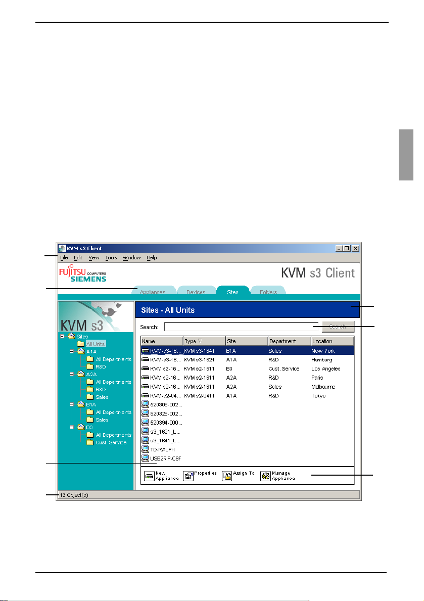
3.1.1 Window features
The Explorer window is divided into several areas: the View Selector buttons, the Group
Selector pane, and the Unit Selector pane. The content of these areas changes, based
on whether a target device or an appliance is selected or what task is to be completed.
Figure 1 shows the window areas; descriptions follow in Table 1 on page 14.
Click one of the View Selector tabs to view the switching system organized by
categories: Appliances, Devices, Sites, or Folders. The Explorer’s default display is
user-configurable. For more information, see “Customizing the window display” on
page 14.
A
B
E
F
C
D
Figure 1: Explorer window areas
590-590-609A
G
13
Page 24

Customizing the window display KVM s3 Client Explorer
Area Description
A Menu bar: Provides access to many of the features in the software.
B View Selector pane: Contains View Selector buttons for choosing the Explorer
view. Clicking a button shows the switching system organized by the button
category: Appliances, Devices, Sites, or Folders. You can configure which
button is visible by default.
C Unit list: Displays a list of target devices, appliances, and other selectable
units contained in the currently selected group, or the results of the search
executed from the Search bar.
D Status bar: Displays the number of units shown in the Unit list.
E Unit Selector pane: Contains the Search bar, Unit list, and Task buttons that
correspond to the selected view or group.
F Search bar: Gives you the ability to search the database for the text entered in
the Search field.
G Task buttons: Represent tasks that can be executed. Some buttons are
dynamic, based on the unit selected in the Unit list, while other buttons are
fixed and always present.
Table 1: Explorer window areas
3.1.2 Customizing the window display
You can resize the Explorer window at any time. Each time you start the application, the
Explorer window opens to its default size and location.
A split-pane divider that runs from top to bottom separates the Group Selector pane and
the Unit Selector pane. You can move the divider left and right to change the viewing
area of these two panes. Each time the Explorer is opened, the divider returns to its
default location.
You can specify which view (Appliances, Devices, Sites, or Folders) is visible on startup
or you can let the Explorer determine it. For more information, see “Viewing or changing
the selected view on startup” on page 26.
You can change the order and sorting of the Unit list by clicking the sort bar above the
column. An upward-pointing arrow in a column header indicates that the list is sorted by
that field name in ascending order. A downward-pointing arrow indicates the list is
sorted by that field name in descending order.
14
590-590-609A
Page 25
KVM s3 Client Explorer Adding an appliance
3.2 Adding an appliance
Before you can access the appliance through the software, you must add it to the
software database. After an appliance is added, it is visible in the Unit list. You can
either manually add or discover an appliance.
3.2.1 Adding an appliance with an assigned IP address
Complete one of the following steps:
•Select File - New - Appliance from the Explorer menu.
-or-
• Click the New Appliance button.
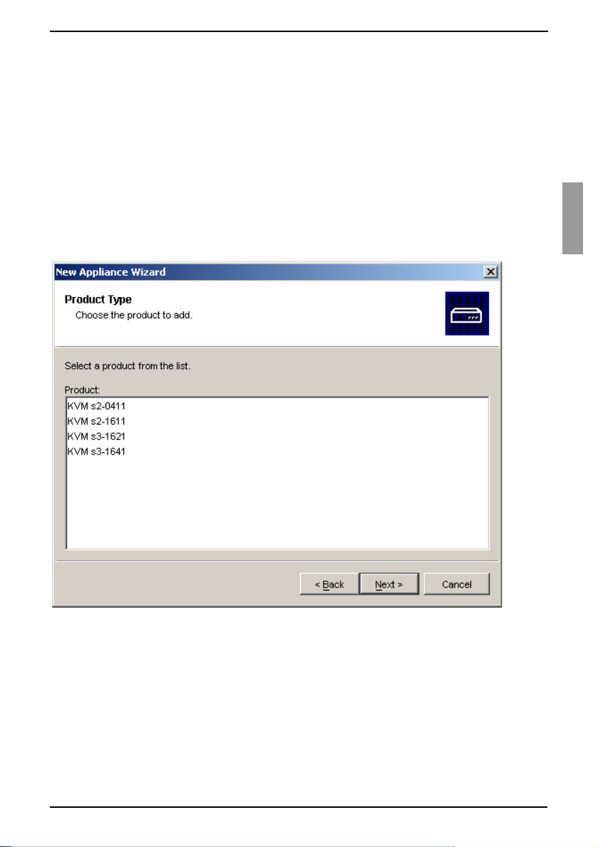
The New Appliance Wizard opens. Click Next.
Figure 2: New Appliance Wizard
Select the type of appliance you are adding. Click Next.
Click Yes to indicate that the appliance has an assigned IP address, then click
Next.
Type the IP address and click Next.
The software searches for the appliance.
The software searches for the indicated unit as well as all the powered KVM-IAs
and target device names you associated with it in OSCAR, if any. To search for
unpowered KVM-IAs, you can access the resync feature in the Devices category of
the AMP and select the Include Offline KVM-IA check box.
590-590-609A
15
Page 26

Installing a new appliance with no assigned IP address KVM s3 Client Explorer
The Enter Cascade Switch Information window opens if the software detects an
attached cascade switch. This window contains a list of all ports and KVM-IA EIDs
(Electronic Identification Numbers) retrieved from the appliance and the cascaded
switch types to which they are connected, if any. When this window first opens, all
cascade switch names are set to None. Detected cascade switches have an icon
next to the pull-down menu.
a. The Existing Cascaded Switches field contains all the current cascade
switch types defined in the database. Click Add, Delete, or Modify to alter the
list.
b. Associate the applicable cascade switch types from the pull-down menus for
each KVM-IA that has a cascade switch attached.
When you reach the final page of the Wizard, click Finish to exit the Wizard and
return to the main window. The appliance is now included in the Unit list.
3.2.2 Installing a new appliance with no assigned IP
address
Complete one of the following steps:
•Select File - New - Appliance from the Explorer menu
-or-
• Click the New Appliance button.
The New Appliance Wizard opens. Click Next.
Click No to indicate that the appliance does not have an assigned IP address, then
click Next.
The Network Address window opens. Type the IP address, subnet mask, and gate-
way you want to assign to the appliance and then click Next.
The software searches for any appliances that do not have assigned IP addresses.
Select the unit to add from the list of new appliances that were found and then
click Next.
The Configuring Appliance window indicates whether the IP information was config-
ured. If the configuration is complete, the software searches for the new appliance.
Click Next.
The software also searches for all KVM-IAs and target device names associated
with the appliance.
The Enter Cascade Switch Information window opens if the software detects an
attached cascade switch. This window contains a list of all ports and KVM-IA EIDs
retrieved from the appliance and the cascade switch types to which they are
connected, if any.
a. The Existing Cascaded Switches field contains all the current cascade switch
types defined in the database. Click Add, Delete, or Modify to alter the list.
b. Associate the applicable cascade switch type from the pull-down menus for
each KVM-IA that has a cascade switch attached.
When complete, click Finish to exit the Wizard and return to the main window. The
appliance is now included in the Unit list.
16
590-590-609A
Page 27

KVM s3 Client Explorer Discovering an appliance by IP address
3.2.3 Discovering an appliance by IP address
Select Tools - Discover from the Explorer menu. The Discover Wizard opens.
Click Next. The Address Range page opens.
Type the range of IP addresses to search on the network in the To and From boxes.
Use IP address dot notation.
Click Next.
Complete one of the following steps:
• The Searching Network progress window opens. Progress text indicates how
many addresses have been probed from the total number specified by the
range, and the number of appliances found (for example, 21 of 100 addresses
probed: 3 appliances found). If one or more new appliances are discovered,
the Wizard shows the Select Appliances to Add page. From this page, you can
select the appliances to add to the local database.
-or-
• If no new appliances were found (or if you clicked Stop), the Wizard shows the
No New Appliances Found page. You can try entering a different range to
search or add the appliances manually.
Select one or more appliances to add and click the Add (>) icon to move the selec-
tion or selections to the Appliances to Add list. When the Appliances to Add list contains all the appliances you want to add, click Next.
The Adding Appliances progress bar window opens. Once all of the appliances
have been added to the local database, the Discover Wizard Completed page
opens. Click Finish to exit the Wizard and return to the main window. The new
appliance is now visible in the Unit list.
If one or more appliances cannot be added to the local database for any reason,
the Discover Wizard Not All Appliances Added page opens. This page lists all of the
appliances that you selected and the status for each. The status indicates if an
appliance was added to the local database and if not, why the process failed. Click
Done when you are finished reviewing the list.
If an appliance already exists in the database with the same IP address as a discovered
unit, then the discovered unit is ignored and is not listed on the next Wizard page.
The Discover Wizard automatically finds target devices attached to the appliance. After
running the Discover Wizard, access the applicable AMP and click the Resync button
on the Devices category to find target devices attached to the appliance.
3.3 Accessing appliances
Clicking the Appliances tab opens a list of the appliances currently defined in the
local database. The Group Selector pane is visible if two or more appliance types are
defined. Click All Appliances or click on a folder to view all appliances of a particular
type.
A user name and password prompt opens if this is the first unit access attempt during
the KVM s3 Client session. After a unit is accessed, subsequent access attempts for
any unit that uses the same user name and password credentials during this KVM s3
Client session do not require a user name and password. The software provides
590-590-609A
17
Page 28
Clearing login credentials KVM s3 Client Explorer
credential caching that captures credentials upon first use and automates the
authentication of subsequent unit connections.
3.3.1 Clearing login credentials
Open the Explorer and go to Tool s - Clear Login Credentials.
Accessing the appliance opens the AMP for that appliance. For more information,
see the See Chapter 5, “Appliance Management Panel”, beginning on page 61 for
more information..
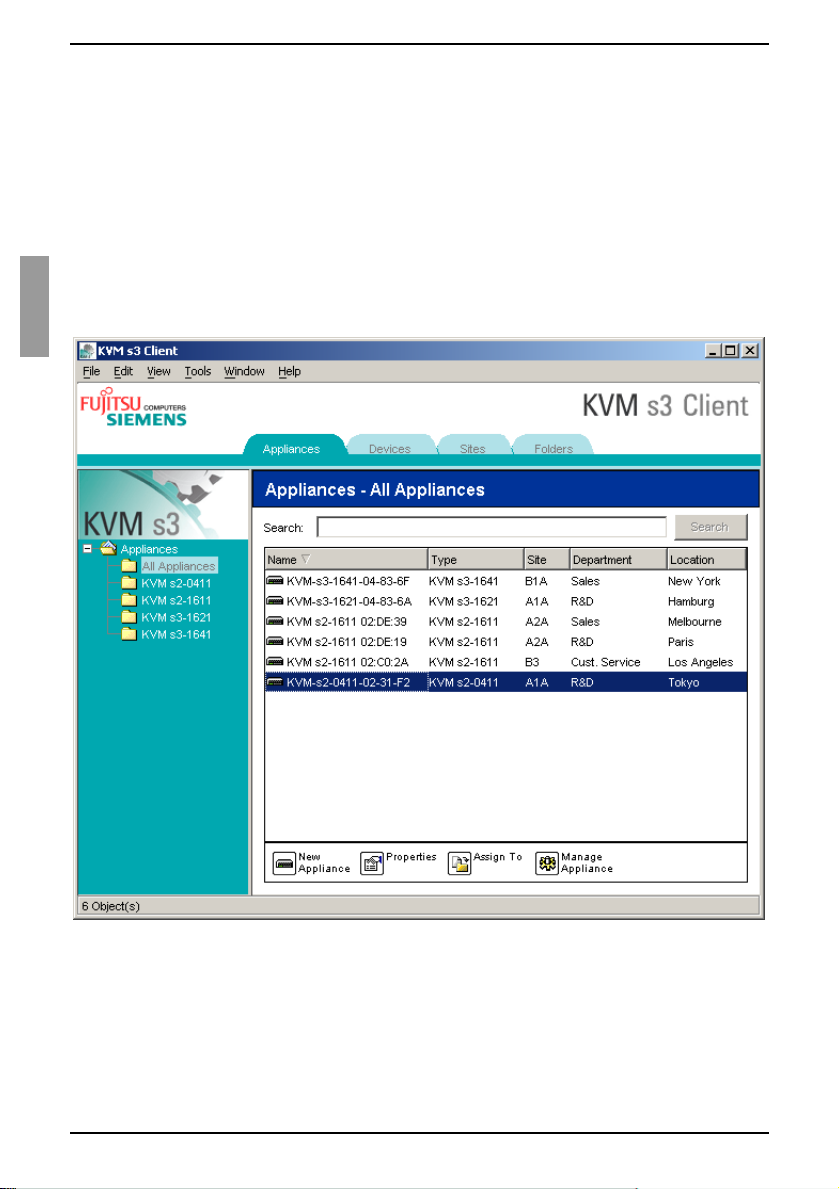
3.3.2 Logging in to an appliance
Click the Appliances tab in the Explorer.
Figure 3: Appliances in the Explorer
Complete one of the following steps:
• Double-click on an appliance in the Unit list.
-or-
• Select an appliance, and then click the Manage Appliance button.
-or-
18
590-590-609A
Page 29

KVM s3 Client Explorer Accessing target devices
• Right-click on an appliance. A pop-up menu opens. Select Manage Appliance
from the pop-up menu.
-or-
• Select an appliance in the Unit list and press Enter.
If a user name and password prompt opens, type the user name and password. If
this is the first appliance access since initialization or reinitialization, the
default user name is Admin (case sensitive) with no password.
Complete one of the following steps:
•Click OK to access the appliance. This opens the AMP for the appliance. For
more information about the AMP, see See Chapter 5, “Appliance Management
Panel”, beginning on page 61 for more information.
-or-
•Click Cancel to exit without logging in.
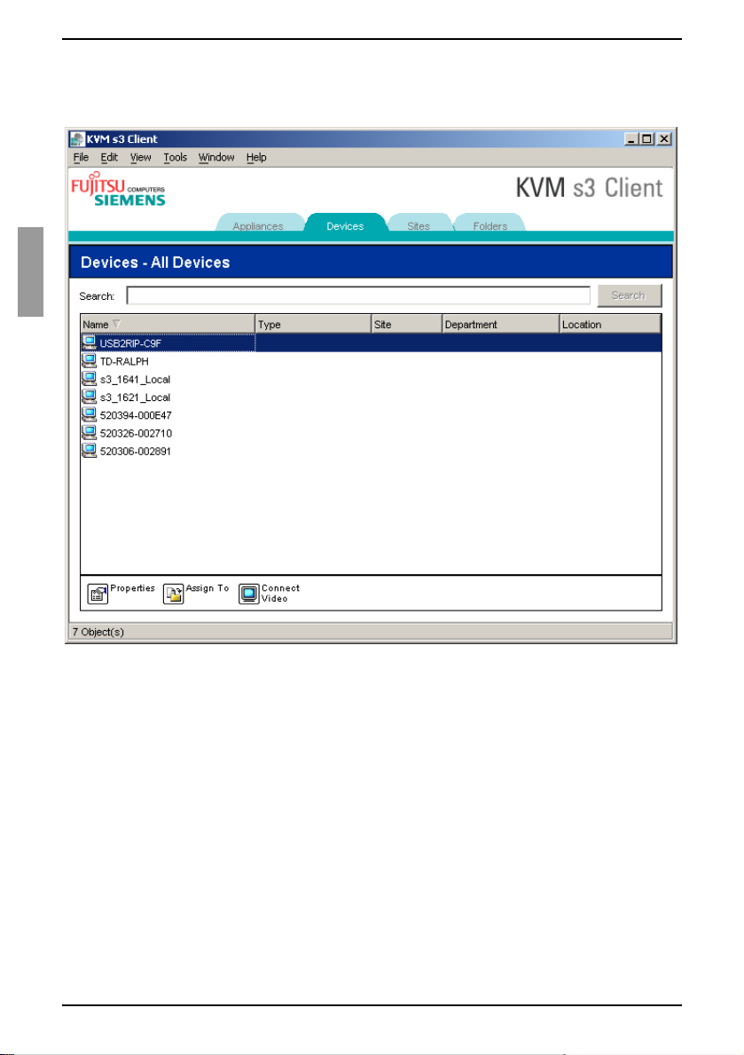
3.4 Accessing target devices
Clicking the Devices tab opens a list of target devices such as servers, routers, and
other managed equipment that is defined in the local database. The Group Selector
pane is visible if two or more device types are defined. Click All Devices or click on a
folder to view all target devices of a particular type.
A user name and password prompt opens if this is the first unit access attempt during
the KVM s3 Client session. After a unit is accessed, subsequent access attempts for
any unit that uses the same user name and password credentials during this KVM s3
Client session do not require a user name and password. The software provides
credential caching that captures credentials upon first use and automates the
authentication of subsequent unit connections.
To clear login credentials, in the Explorer go to Tools - Clear Login Credentials.
When you select a device and click the Connect Video button, the Video Viewer
launches. The Video Viewer allows you full keyboard, video and mouse control over a
device. If a URL has been defined for a given device, then the Browse button will also
be available. The Browse button will launch the configured Web browser, if any, or
default browser to the defined URL for that device.
For more information, see “Customizing properties” on page 21 and “Customizing
options” on page 25.
You can also scan through a customized list of devices using the Thumbnail Viewer.
This view contains a series of thumbnail frames, each containing a small, scaled, noninteractive version of a device screen image. For more information, see “Using scan
mode” on page 44.
590-590-609A
19
Page 30
Accessing a target device KVM s3 Client Explorer
3.4.1 Accessing a target device
Click the Devices tab in the Explorer.
Figure 4: Devices in the Explorer
Complete one of the following steps:
• Double-click on a target device in the Unit list.
-or-
• Select a target device, and then click Connect Video or Browse if an URL is
configured. Only the applicable button or buttons for the selected target device
are visible.
-or-
• Right-click on the target device. Select the connection entry from the pop-up
menu and then click Connect Video or Browse if an URL is configured. Only
the applicable entry for the selected target device is visible.
-or-
• Select a target device in the Unit list and press Enter.
20
590-590-609A
Page 31

KVM s3 Client Explorer Searching for a target device in the local database
If a browser is used for access, no user name and password prompt opens.
If the Video Viewer is used for access, a user name and password prompt opens if
this is the first access attempt during the KVM s3 Client session.
After a unit is accessed, subsequent access attempts for any unit that uses the
same user name and password credentials during this KVM s3 Client session do
not require a user name and password.
The configured access method for that target device opens in a new window.
3.4.2 Searching for a target device in the local database
Click the Devices tab and insert the cursor in the Search field.
Type the search information. This could be a target device name or a property such
as type or location.
Click the Search button. The results are included in the Unit list.
Complete one of the following steps:
• Review the results of the search.
-or-
• Click the Clear Results button to open the entire list again.
Auto-searching by typing in the Unit list
Click the Devices tab, then click on any item in the Unit list.
Begin typing the first few characters of a target device name. The highlight moves
to the first target device name beginning with those characters. To reset the search
so you can find another target device, pause for a few seconds and then type the
first few characters of the next target device.
If the target device you are attempting to access is currently being viewed by another
user, you can preempt the user so you can have access to that target device, or request
a shared session with that user (KVM sharing is available only on KVM s2-0411, KVM
s3-1621, and KVM s3-1641 appliances). For more information, see “Using preemption”
on page 38 and “Using digital share mode” on page 41.
3.5 Customizing properties
The Properties window in the Explorer contains the following tabs: General, Network,
Information, and, if the selected unit is a device, Connections. Use these tabs to view
and change properties for the selected unit.
3.5.1 Viewing and changing general properties
In general properties, you can specify a unit Name, Type (target device only), Icon, Site,
Department, and Location. (To customize the Site, Department, and Location field
labels, see “Changing custom field names” on page 25.)
590-590-609A
21
Page 32

Viewing or changing general properties KVM s3 Client Explorer
3.5.2 Viewing or changing general properties
Select a unit in the Unit list.
Complete one of the following steps:
•Select View - Properties from the Explorer menu.
-or-
• Click the Properties button.
-or-
• Right-click on the unit. Select Properties from the pop-up menu.
The General Properties window opens.
Figure 5: Device General Properties window
In the Name field, type a 1- to 32-character unique name. (This name is local to the
software database; the appliance database might contain a different name for this
unit.)
The Typ e field is read-only for appliances. For a target device, select a type from
the pull-down menu or enter a 1 to 32 character type in the text field.
In the Icon field, select an icon from the pull-down menu.
22
590-590-609A
Page 33

KVM s3 Client Explorer Viewing and changing network properties
In the Site, Department, and Location fields, select an entry from the pull-down
menu or enter a 1 to 32 character Site, Department, or Location in the corresponding text field.
Complete one of the following steps:
• Click another tab to change additional properties.
-or
• If finished, click OK to save the new settings.
-or-
•Click Cancel to exit without saving the new settings.
3.5.3 Viewing and changing network properties
For an appliance, network properties include the address of the appliance.
For a target device, network properties specify the URL to use when establishing a
browser connection to the target device. When this field contains a value, the Browse
button is visible in the Explorer task bar.
Select a unit in the Unit list.
Complete one of the following steps:
•Select View - Properties from the Explorer menu.
-or-
• Click the Properties button.
-or-
• Right-click on the unit. Select Properties from the pop-up menu.
The Properties window opens.
Click the Network tab.
In the Address field (appliances only), enter the appliance address in IP dot nota-
tion or 1 to 128 character host name. The address cannot be blank, a loopback
address, or all zeros. You cannot enter duplicate addresses.
In the Browser URL field (devices only), enter a 1 to 256 character URL for estab-
lishing a browser connection.
Complete one of the following steps:
• Click another tab to change additional properties.
-or-
• If finished, click OK to save the new settings.
-or-
•Click Cancel to exit without saving the new settings.
590-590-609A
23
Page 34

Viewing and changing information properties KVM s3 Client Explorer
3.5.4 Viewing and changing information properties
Information properties include description, contact phone number, and comment
information; you can use these fields to store any information you require.
Select a unit in the Unit list.
Complete one of the following steps:
•Select View - Properties from the Explorer menu.
-or-
• Click the Properties button.
-or-
• Right-click on the unit. Select Properties from the pop-up menu.
The Properties window opens.
Click the Information tab. You can enter any information in the following fields.
a. In the Description field, enter 0 to 128 characters.
b. In the Contact field, enter 0 to 128 characters.
c. In the Contact Phone Number field, enter 0 to 64 characters.
d. In the Comment field, enter 0 to 256 characters.
Complete one of the following steps:
• Click another tab to change additional properties.
-or-
• If finished, click OK to save the new settings.
-or-
•Click Cancel to exit without saving the new settings.
3.5.5 Viewing connections properties
Connections properties are available only for target devices and are read-only. The
display indicates the physical connection path that is used to access this target device
and the connection type, such as video.
Select a target device in the Unit list.
Complete one of the following steps:
•Select View - Properties from the Explorer menu.
-or-
• Click the Properties button.
-or-
• Right-click on the unit. Select Properties from the pop-up menu.
The Properties window opens.
Click the Connections tab.
24
590-590-609A
Page 35

KVM s3 Client Explorer Customizing options
3.6 Customizing options
Set general options for the Explorer in the Options window. General options include
custom field names, selected view on startup, browser application, and DirectDraw
support.
3.6.1 Viewing and changing general options
You can customize options for the Explorer, including custom name fields, default view,
and default browser.
3.6.1.1 Changing custom field names
In the Custom field labels area, you can change the Site, Department, and Location
headings that are visible in the Group and Unit Selector panes. You can group units in
ways that are meaningful to you. The Department field is a subset of Site.
Select Tools - Options from the Explorer menu. The General Options window opens.
Figure 6: General Options window
590-590-609A
25
Page 36

Viewing and changing general options KVM s3 Client Explorer
In the Custom field labels area, select a field label to modify and click the Modify
button. The Modify Custom Field Label window opens. Remember that the Depart-
ment field is a subset of the Site field, even if it is renamed. Type the 1 to 32 character singular and plural versions of the new field label. You can use embedded
spaces but not leading or trailing spaces. You cannot use blank field labels.
Complete one of the following steps:
• If finished, click OK to save the new settings.
•Click Cancel to exit without saving the new settings.
3.6.1.2 Viewing or changing the selected view on startup
The “Selected view on startup option” specifies the view that is visible when the software
opens, either Appliances, Devices, Sites, or Folders. You can select a view or let the
Explorer determine the view. When you let the Explorer determine the view, the Devices
view is visible if you have one or more target devices defined. If you do not, the
Appliances view is visible.
Select Tools - Options from the Explorer menu. The General Options window
opens.
Complete one of the following steps:
• If you want the Explorer to determine the best view on startup, select the
Default check box.
-or-
• If you want to specify which view opens on startup, clear the Default check box
and select Appliances, Devices, Sites, or Folders from the pull-down menu.
Complete one of the following steps:
• If finished, click OK to save the new settings.
-or-
•Click Cancel to exit without saving the new settings.
3.6.1.3 Viewing or changing the default browser
The Browser option specifies the browser application that opens when you click the
Browse button for a target device that has URL defined, or when the KVM s3 Client
online help is opened. You can either enable the default browser application of the
current computer or select among other available browsers.
Select Tools - Options from the Explorer menu. The General Options window
opens.
Complete one of the following steps:
•In the Browser field, select the Launch Default Browser check box to specify
the default system browser.
-or-
• Clear the Launch Default Browser check box. Click the Browse button and
select a browser executable on the computer. You can also enter the full path
name of the browser executable.
Complete one of the following steps:
• If finished, click OK to save the new settings.
-or-
•Click Cancel to exit without saving the new settings.
26
590-590-609A
Page 37

KVM s3 Client Explorer Viewing and changing general options
3.6.1.4 Viewing or changing DirectDraw support (Windows only)
The DirectDraw option affects operation of the Video Viewer when running on Windows
operating systems. The software supports DirectDraw, a standard that you can use to
directly manipulate video display memory, hardware blitting, hardware overlays, and
page flipping without the intervention of the Graphical Device Interface (GDI). This can
result in smoother animation and improvement in the performance of display-intensive
software.
However, if the machine has a software cursor or pointer shadow enabled, or if the
video driver does not support DirectDraw, you can experience a flicker in the mouse
cursor when over the title bar of the Video Viewer. You can either disable the software
cursor or pointer shadow, load a new target device driver for the video card, or disable
DirectDraw.
Select Tools - Options from the Explorer menu. The General Options window
opens.
In the DirectDraw field, select or clear the DirectDraw check box.
Complete one of the following steps:
• If finished, click OK to save the new settings.
-or-
•Click Cancel to exit without saving the new settings.
590-590-609A
27
Page 38

Creating and managing folders KVM s3 Client Explorer
3.7 Creating and managing folders
Use folders to create a customized organizational system for groups of units. For
example, you might create a folder for critical target devices or for remote target
devices. Folders are listed under the Folders tab in the Explorer. You can name and
structure folders in any way you choose.
Select the Folders tab.
Figure 7: Folders in the Explorer
Complete one of the following steps:
• Click on the top-level Folders node and select File - New - Folder.
-or-
• To create a nested folder, click on an existing folder and select File - New -
Folder in the Explorer menu. The New Folder window opens.
Type a 1 to 32 character name. Folder names are not case sensitive. You can use
embedded spaces but not leading or trailing spaces. You cannot use duplicate
folder names at the same level, but you can use duplicate folder names on different
levels.
Click OK. The new folder is listed in the Group Selector pane.
28
590-590-609A
Page 39

KVM s3 Client Explorer Assigning units
To assign a unit to a folder, see “Assigning units” on page 29. To rename or delete a
folder, see “Renaming” on page 31 and “Deleting” on page 30.
3.8 Assigning units
After you have created a new Site, Location, or Folder, you can assign a unit to that
organization. The Assign menu item is only enabled when a single unit is selected in
the Unit list (the custom assignment targets are defined in the General Properties
window).
There are three ways to assign a unit to a Site, Location, or Folder: editing the unit
Properties window, using the Assign function, or dragging and dropping.
3.8.1 Assigning a unit using the Properties window
Select a unit in the Unit list.
Complete one of the following steps:
•Select View - Properties from the Explorer menu.
-or-
• Click the Properties button. The Properties window opens.
Click the General tab. Select the Site, Department, or Location to which you want
to assign the unit.
Complete one of the following steps:
•Click OK to save the assignment.
-or-
•Click Cancel to exit without saving the assignment.
3.8.2 Assigning a unit using the Assign function
Select a unit in the Unit list.
Complete one of the following steps:
•Select Edit - Assign from the Explorer menu.
-or-
• Click the Assign To button.
-or-
• Right-click on a unit and select Assign To from the pop-up menu.
The Assign To window opens.
In the Category pull-down menu, select Site, Location, or Folder.
In the Target list, select the assignment you want to designate. The target list is
empty if no Site, Location, or Folder has been defined in the local database.
Complete one of the following steps:
•Click OK to save the assignment.
-or-
•Click Cancel to exit without saving the assignment.
590-590-609A
29
Page 40

Assigning a unit using drag and drop KVM s3 Client Explorer
3.8.3 Assigning a unit using drag and drop
To use drag and drop, click and hold on a unit in the Unit list.
Drag the item on top of a folder icon (node) in the tree view of the Group Selector
pane. Release the mouse button.
The item is now visible in the Unit list when you click that node.
A unit cannot be moved to All Departments, All Units, or the root Sites node. Units can
only be moved one at a time.
3.9 Deleting
The delete function works according to what is currently selected in the Group and Unit
Selector panes. When you select and delete a unit in the Unit list, it is removed from the
local database. When you select and delete an item in the tree view of the Group
Selector pane, you can delete Devices, Sites, Departments, or Folders; however, none
of the actions result in units being deleted from the local database.
3.9.1 Deleting a unit
Select the unit or units to delete from the Unit list.
Complete one of the following steps:
•Select Edit - Delete from the Explorer menu.
-or-
• Right-click on a unit and select Delete from the pop-up menu.
-or-
• Press the Delete key on the keyboard.
A window prompts you to confirm the number of units you want to delete. If you are
deleting an appliance, the window includes a Delete Associated Devices check
box. Select or clear the check box as needed. If you do not delete the associated
target devices, they are still visible in the target devices list but you cannot connect
to them unless they have a URL assigned, in which case you can connect to the
target device using a browser.
Complete one of the following steps:
•Click Yes to confirm the deletion. You might receive additional message
prompts, depending on the configuration. Respond as needed. The units are
deleted.
-or-
•Click No to cancel the deletion.
30
590-590-609A
Page 41

KVM s3 Client Explorer Deleting a target device Type, Site, Department, or Folder
3.9.2 Deleting a target device Type, Site, Department, or
Folder
Select the target device Type, Site, Department, or Folder to delete from the Group
Selector pane.
Complete one of the following steps:
•Select Edit - Delete from the Explorer menu.
-or-
• Press the Delete key on the keyboard.
You are prompted to confirm the number of units that are affected by this deletion.
Complete one of the following steps:
•Click Yes to confirm the deletion. You might receive additional message
prompts, depending on the configuration. Respond as needed. The element is
deleted.
-or-
•Click No to cancel the deletion.
3.10 Renaming
The rename function works according to what is currently selected. You might select
and rename an appliance or a target device from the Unit list. You can select and
rename unit Types, Sites, Departments, and Folder names in the tree view of the Group
Selector pane.
3.10.1 Renaming a unit Type, Site, Department, or Folder
Complete one of the following steps:
• Select a unit from the Unit list.
-or-
• In the Group Selector pane, select the unit Type, Site, Department, or Folder
to rename.
Complete one of the following steps:
•Select Edit - Rename from the Explorer menu.
-or-
• Right-click on the unit Type, Site, Department, or Folder in the Unit list and
select Rename from the pop-up menu. The Rename window opens.
Type a 1 to 32 character name. You can use embedded spaces but not leading or
trailing spaces. (This name is local to the software database; the appliance database might contain a different name for this unit.)
Complete one of the following steps:
•Click OK to save the new name.
-or-
•Click Cancel to exit without saving changes.
590-590-609A
31
Page 42

Managing the software database KVM s3 Client Explorer
For a unit Type, Site, Department, or Folder, you cannot use duplicate names, including
the same name with different cases, with two exceptions: department names can be
duplicated on different sites and folder names can be duplicated on different levels.
3.11 Managing the software database
Each computer running the software contains a local database that records the
information that you enter about the units. If you have multiple computers, you can
configure one computer and then save a copy of this database and load it into the other
computers to avoid unnecessarily reconfiguring each computer. You can also export the
database for use in another application.
3.11.1 Saving and loading a database
You can save a copy of the local database and then load it back to the same computer
where it was created, or onto another computer running the software. The saved
database is compressed into a single Zip file.
While the database is being saved or loaded, you cannot use or modify the database.
You must close all other windows, including target device session windows and AMP
windows. If other windows are open, a message prompts you to either continue and
close all open windows or quit and cancel the database save process.
3.11.1.1 Saving a database
Select File - Database - Save from the Explorer menu. The Database Save window
opens.
Enter a file name and select a location to save the file.
Click Save. A progress bar is visible during the save. When finished, a message
indicates that the save is complete and you are returned to the main window.
3.11.1.2 Loading a database
Select File - Database - Load from the Explorer menu. The Database Load window
opens.
Browse to select a database to load.
Click Load. A progress bar is visible during the load. When finished, a message
indicates that the load is complete, and you are returned to the main window.
3.11.2 Exporting a database
You can export fields from the local database to a Comma Separated Value (CSV) file
or Tab Separated Value (TSV) file. The following database fields are exported:
Appliance flag Type Name
Address Custom Field 1 Custom Field 2
Custom Field 3 Description Contact Name
Contact Phone Comments Browser URL
The first line of the exported file contains the column names for the field data. Each
additional line contains the field data for a unit. The file contains a line for each unit
defined in the local database.
32
590-590-609A
Page 43

KVM s3 Client Explorer Exporting a database
3.11.2.1 Exporting a database
Select File - Database - Export from the Explorer menu. The Database Export win-
dow opens.
Type a file name and browse to the location to save the exported file.
Click Export. A progress bar is visible during the export. When finished, a message
indicates that the export is complete, and you are returned to the main window.
590-590-609A
33
Page 44

Exporting a database KVM s3 Client Explorer
34
590-590-609A
Page 45

4 Video Viewer
About the Video Viewer
When you connect to a target device using the Video Viewer, the desktop of the target
device is visible in a separate Video Viewer window. You can see both the local cursor
and the target device cursor.
From this window, you can access all the normal functions of this target device as if you
were sitting in front of it. You can also perform viewer-specific tasks such as sending
macro commands to the target device.
You can open the Video Viewer for target devices on all FSC KVM appliances.
If the target device you are attempting to access is currently being viewed by another
user, you have several options depending on the appliance model and your access
rights. If you are an administrator, you can share the session, preempt the session, or
observe the session in stealth mode.
Only the KVM s2-0411, KVM s3-1621, and the KVM s3-1641 appliances
support
For more information about access rights and session types, see “Video session types”
on page 36 and “Managing local user accounts” on page 78.
For a detailed description of the Video Viewer window and its designated elements, see
Figure 10 on this page and Table 4 on page 48.
advanced features, such as sharing and stealth mode.
Figure 8: Video Viewer window (as shown in the Windows XP operating system)
590-590-609A
35
Page 46

Accessing the Video Viewer Video Viewer
4.1 Accessing the Video Viewer
Click the Devices tab in the Explorer.
Complete one of the following steps:
• Double-click on the target device in the Unit list.
-or-
• Select the target device, then click the Connect Video button.
-or-
• Right-click on the target device. Select Connect Video from the pop-up menu.
-or-
• Select the target device and press Enter
If the target device is not being viewed by another user, the Video Viewer opens in a
new window. If the target device is being accessed by another user, you might have the
option to preempt the session, share the session, or observe the session in stealth
mode, depending on your access rights.
If this is the first unit access of the KVM s3 Client session, a user name and password is
required.
Important: A user name and password is not required for any subsequent access
attempts during the same KVM s3 Client session unless you clear the current cached
credentials.
4.1.1 Closing a Video Viewer session
.
•Select File - Exit from the Video Viewer menu.
•Click X to close the Video Viewer session.
4.2 Video session types
When using the Video Viewer with the KVM s2-0411, KVM s3-1621, and KVM s3-1641
appliances, you can choose which type of session you want to operate. In addition to
operating a normal KVM session, administrators and users with certain access rights
can also operate a session in an exclusive mode, share the session with one or more
users, observe a session in stealth mode, or scan multiple devices. The current type of
session is indicated by an icon on the right side of the Video Viewer toolbar.
Video session types are outlined in Table 2 on page 37.
36
590-590-609A
Page 47

Video Viewer Video session types
Session
Icons Description
types
Active (normal) You are conducting a normal KVM session that is not
exclusive, but is not currently shared. An active session
icon is visible.
Locked (normal) Your administrator has configured the appliance to lock
KVM and Virtual Media (VM) sessions together. You have
a normal KVM session and have opened a VM session.
Your KVM session cannot be shared or preempted, and it
is not subject to inactivity time-out. It can be terminated by
an administrator. For more information, see “Using virtual
media” on page 56.
Exclusive You have exclusive control over the targets. During this
KVM session the connection to the target device cannot be
shared, but it can be preempted or observed in stealth
mode by an administrator.
Active sharing:
(primary)
Active sharing:
(secondary)
Passive sharing You can view the video ouput of the target device, but you
You are the first user to connect to the target device, and
you have allowed other users to share the KVM session.
You can view and interact with the target device while
sharing the KVM session with a primary user and, possibly,
other secondary users.
are not allowed to have keyboard and mouse control over
the target device.
Stealth You can view the video output of the target device without
the permission or knowledge of the primary user. You
cannot have keyboard and mouse control over the target
device. This session type is available for administrators
only.
Scanning (No
status
Icon)
Table 2: Video session types
590-590-609A
You can monitor up to 16 target devices in thumbnail view.
No status indicator icon is visible when in scan mode.
37
Page 48

Using preemption Video Viewer
4.3 Using preemption
Preemption provides a means for users with sufficient privilege to take control of a target
device from another user with lesser or equal privilege.
If preemption warnings are enabled, all users sharing the connection that is being
preempted are warned, unless the target device is connected to a KVM s3-1621 or
KVM s3-1641 appliance. If the primary user has the corresponding access rights, they
can reject the preemption.
Table 3 outlines the preemption scenarios and detailed scenarios in which preemption
requests can be rejected.
Current user Preempted by Preemption can be
rejected
User Local user No
User User administrator No
User Appliance administrator No
Appliance administrator Local user Yes
Appliance administrator Appliance administrator Yes
User administrator Local user No
User administrator User administrator Yes
User administrator Appliance administrator No
Local user User administrator Yes
Local user Appliance administrator Yes
Table 3: Preemption scenarios
38
590-590-609A
Page 49

Video Viewer Preemption of a user by an administrator
4.3.1 Preemption of a user by an administrator
If an administrator attempts to access a target device that is being accessed by a user,
a message requests that the administrator wait while the user is informed that their
session will be preempted. The user cannot reject the preemption request and will be
disconnected.
If the target device is attached to a KVM s2-1611 appliance, the
user will not be warned.
The time period given before disconnection is defined by the Video session preemption
timeout setting in the Global - Sessions category. For information, see “Configuring
Global Network settings” on page 62 and “Configuring Global Session settings” on
page 64.
4.3.2 Preemption of a local user/administrator by an
administrator
If an administrator attempts to access a target device that is being accessed by the local
user or by another administrator with equal privileges, the currently connected user can
accept or reject the preemption request. A message asks the connected local user or
administrator whether they want to accept the preemption request.
If the target device is attached to a KVM s2-1611 appliance, the
user will not be given the option to accept or reject preemption.
If the preemption request is rejected, a message is displayed informing the administrator
that their request has been rejected and that they cannot access the target device.
In scenarios where a preemption request can be rejected, the Session Preemption
Request window opens. Use this window to accept the preemption request by clicking
the Accept button, or reject the preemption request by clicking the Reject button or by
closing the window.
To preempt the current user, complete the following steps:
Click the Devices tab in the Explorer.
Complete one of the following steps:
• Double-click on the target device in the Unit list.
-or-
• Select the target device, then click the Connect Video button.
-or-
• Right-click on the target device. Select Connect Video from the pop-up menu.
-or-
• Select the target device and press Enter
When another user is viewing this target device, a message indicates that the target
device is already involved in a KVM session.
590-590-609A
.
39
Page 50

Using exclusive mode Video Viewer
If the appliance has connection sharing enabled, you are given the option to share
the session. For information about connection sharing, see “Using digital share
mode” on page 41. If your access rights (as compared with those of the primary
user) allow it, you are prompted to either share or preempt the existing session. If
the option is available, select Preempt.
Complete one of the following steps:
•Click OK or Yes. A preemption notification is sent to the primary user.
Depending on your access rights, the primary user might be able to reject the
preemption.
-or-
•Click No to let the primary user retain the connection.
If the preemption completes, the Video Viewer of the target device session opens.
For more information about access levels, see “Managing local user accounts” on
page 78.
4.4 Using exclusive mode
When operating a video session in exclusive mode, you cannot receive any share
requests from other users. However, administrators can choose to preempt (or
terminate) the session or monitor the session in stealth mode.
You cannot use exclusive mode when connecting to a target device on a
KVM s2-1611 appliance.
4.4.1 Enabling exclusive KVM sessions on an appliance
Click the Appliances tab in the Explorer.
Complete one of the following steps:
• Double-click on an appliance in the Unit list.
-or-
• Select an appliance from the Unit list, then click the Manage Appliance button.
• Right-click on an appliance in the Unit list. Select Manage Appliance from the
pop-up menu.
-or-
• Select an appliance in the Unit list and press Enter
Click the Settings tab in the AMP.
Select the Global - Sessions subcategory.
Select the Enable Share Mode check box in the Connection Sharing area.
40
.
590-590-609A
Page 51

Video Viewer Accessing the Video Viewer in exclusive mode
Select Exclusive Connections in the Connection Sharing area.
Complete one of the following steps:
•Click Apply to save any changes without exiting the AMP.
-or-
•Click OK to save any changes and exit the AMP.
-or-
•Click Cancel to exit the AMP without saving any changes.
4.4.2 Accessing the Video Viewer in exclusive mode
Only the primary user of a shared connection or the only user of a non-shared session
can access the Video Viewer in exclusive mode.
Open a KVM session to a target device.
Select Too ls - Exclusive Mode from the Video Viewer toolbar.
If the KVM session is currently shared, only the primary user can designate the
session as exclusive. A message warns the primary user that secondary sessions
will be terminated if an exclusive session is invoked.
Complete one of the following steps:
•Select Yes to terminate the sessions of the secondary users.
-or-
•Select No to cancel the exclusive mode action.
Secondary users cannot share the exclusive KVM session. However, administrators can
still terminate the session, or users with certain access rights can preempt the session.
4.5 Using digital share mode
Multiple users can view and interact with a target device using digital share mode. When
a session is shared, the secondary user can be an active user with keyboard and mouse
control or a passive user that does not have keyboard and mouse control.
You cannot use digital share mode when connecting to a target device on
a KVM s2-1611 appliance.
4.5.1 Configuring an appliance to share KVM sessions
Click the Appliances tab in the Explorer.
Complete one of the following steps:
• Double-click on an appliance in the Unit list.
-or-
• Select an appliance from the Unit list, then click the Manage Appliance button.
-or-
• Right-click on an appliance in the Unit list. Select Manage Appliance from the
pop-up menu.
-or-
• Select an appliance in the Unit list and press Enter
590-590-609A
.
41
Page 52

Configuring an appliance to share KVM sessions Video Viewer
Click the Settings tab in the AMP.
Select the Global - Sessions subcategory.
Select Enable Share Mode in the Connection Sharing area.
You can choose to select Automatic Sharing. This enables secondary users to
automatically share a KVM session without first requesting permission from the
primary user.
Complete one of the following steps:
•Click Apply to save any changes without exiting the AMP.
-or-
•Click OK to save any changes and exit the AMP.
-or-
•Click Cancel to exit the AMP without saving any changes.
To share a digital connection, complete the following steps:
Click the Devices tab in the Explorer.
Complete one of the following steps:
• Double-click on the target device in the Unit list.
-or-
• Select the target device, then click the Connect Video button.
-or-
• Right-click on the target device. Select Connect Video from the pop-up menu.
-or-
• Select the target device and press Enter
.
When another user is viewing this target device, a message indicates that the target
device is already involved in a KVM session.
If connection sharing is enabled on the appliance and your access rights (as
compared with those of the primary user) allow it, you are prompted to either share
or preempt the existing session. If the option is available, select Share.
Complete one of the following steps:
•Click OK or Yes. If Automatic Sharing is not enabled, a share request is sent to
the primary user, who can accept the share request as either an active or
passive (read-only) session, or reject the share request entirely.
-or-
•Click No to cancel the share request.
If the primary user accepts the share request, or if Automatic Sharing is enabled, a KVM
session to the target device session opens, and the session type icon within the new
Video Viewer window indicates if the session status is active or passive. If the request is
rejected, a message indicates that the request was denied. Administrators have several
options at this point. They can either try to connect again and preempt the session or
connect in stealth mode, or they can terminate the session entirely from the AMP Status
tab; see “Managing user sessions” on page 82.
42
590-590-609A
Page 53

Video Viewer Using stealth mode
If you are not prompted to connect in share mode, either the appliance to which the
target device is connected is not configured to allow digital share mode sessions or it is
not a KVM-0411, KVM s3-1621, or KVM s3-1641 appliance.
4.6 Using stealth mode
Administrators can connect to a target device in stealth mode, viewing the video output
of a remote user undetected. When in stealth mode, the administrator does not have
keyboard or mouse control over the target device.
You cannot use stealth mode when connecting to a target device on a
KVM s2-1611 appliance.
4.6.1 Enabling stealth KVM sessions on an appliance
Click the Appliances tab in the Explorer.
Complete one of the following steps:
• Double-click on an appliance in the Unit list.
-or-
• Select an appliance from the Unit list, then click the Manage Appliance button.
-or-
• Right-click on an appliance in the Unit list. Select Manage Appliance from the
pop-up menu.
-or-
• Select an appliance in the Unit list and press Enter
Click the Settings tab in the AMP.
Select the Global - Sessions subcategory.
Select the Enable Share Mode checkbox in the Connection Sharing area.
Select Stealth Connections in the Connection Sharing area.
Complete one of the following steps:
•Click Apply to save any changes without exiting the AMP.
-or-
•Click OK to save any changes and exit the AMP.
-or-
•Click Cancel to exit the AMP without saving any changes.
.
4.6.2 Monitoring a target device in stealth mode
Click the Devices tab in the Explorer.
Complete one of the following steps:
• Double-click on the target device in the Unit list.
-or-
• Select the target device, then click the Connect Video button.
-or-
590-590-609A
43
Page 54

Using scan mode Video Viewer
• Right-click on the target device. Select Connect Video from the pop-up menu.
-or-
• Select the target device and press Enter
If another user is already viewing this target device, a message indicates that the
target device is already involved in a KVM session.
If connection sharing and stealth connections are enabled on the appliance and
your access rights (as compared with those of the primary user) allow it, you are
prompted to either share or preempt the existing session. If the option is available,
select Stealth.
Complete one of the following steps:
•Click OK or Yes.
-or-
•Click No to cancel the stealth request.
A KVM session to the target device opens, and the administrator can view all video
output of the target device while remaining undetected.
If Stealth is not listed as an option, one of the following conditions exists:
• The appliance to which the target device is connected is not configured to allow
Stealth Connections.
-or-
• You do not have the necessary access rights (Stealth permissions follow
Preemption permissions).
-or-
• The appliance to which the target device is connected is not a KVM s2-0411,
KVM s3-1621, or KVM s3-1641 appliance.
.
4.7 Using scan mode
You can view multiple target devices using the scan mode Thumbnail Viewer. This view
contains a series of thumbnail frames, each containing a small, scaled, non-interactive
version of a target device screen image. The target device name and status indicator
are visible below each thumbnail as follows:
• A green circle icon indicates that a target device is currently being scanned.
• A red X icon indicates that the last scan of the target device failed. The scan can
have failed due to a credential or path failure (for example, the target device path on
the appliance was not available). The tool tip for the icon indicates the reason for
the failure.
You can set up a scan sequence of up to 16 target devices to monitor. The scan mode
moves from one thumbnail image to the next, logging into a target device and displaying
an updated target device image for a specified length of time (View Time Per Device),
before logging out of that target device and moving on to the next thumbnail image. You
can also specify a scan delay between thumbnails (Time Between Devices). During the
delay, you can see the last thumbnail image for all target devices in the scan sequence,
but you won’t be logged into any target devices.
44
590-590-609A
Page 55

Video Viewer Accessing scan mode
When you first open the Thumbnail Viewer, each frame is filled with a black background
until a target device image is visible. An indicator icon at the bottom of each frame
displays the target device status. The default thumbnail size is based on the number of
target devices in the scan list.
Scan mode has a lower priority than an active connection. If a user is connected to a
target device, that target device is skipped in the scan sequence, and scan mode
proceeds to the next target device. No login error messages are visible. After the
interactive session is closed, the thumbnail is included in the scan sequence again.
You can disable a target device thumbnail from the scan sequence. The thumbnail
image remains, but it is not updated until it is once again enabled.
4.7.1 Accessing scan mode
Select the Appliance, Devices, Sites, or Folders tab in the Explorer window.
Select two or more target devices in the Unit list by pressing the Shift or Control key.
The Scan Mode button is visible.
Click the Scan Mode button. The Thumbnail Viewer window opens.
Figure 9: Video Viewer - Thumbnail Viewer
590-590-609A
45
Page 56

Setting scan options Video Viewer
4.7.2 Setting scan options
To set scan preferences, complete the following steps:
Select Options - Preferences from the Thumbnail Viewer menu. The
Preferences window opens.
In the View Time Per Device field, enter the time each thumbnail is active during
the scan, in the range of 10 to 60 seconds.
In the Time Between Devices field, enter the time the scan stops between each
target device, in the range of 5 to 60 seconds.
Click OK.
4.7.3 Changing the thumbnail size
Select Options - Thumbnail Size from the Thumbnail Viewer menu.
Select a thumbnail size from the cascaded menu.
4.7.4 Managing the scan sequence
4.7.4.1 Pausing or restarting a scan sequence
Select Options - Pause Scan from the Thumbnail Viewer menu.
The scan sequence pauses at the current thumbnail if the Thumbnail Viewer has a
scan in progress or restarts the scan if currently paused.
4.7.4.2 Disabling a target device thumbnail in the scan sequence
Select a target device thumbnail. Select Thumbnail - “target device name” -
Enable from the Thumbnail Viewer menu. (The Enable menu item state can be tog-
gled from checked (enabled) to unchecked (disabled) each time it is selected).
Right-click on a target device thumbnail and select Disable from the pop-up menu.
Updating of that thumbnail image stops until it is enabled again.
4.7.4.3 Enabling a target device thumbnail in the scan sequence
Select a target device thumbnail. Select Thumbnail - “target device name” -
Enable from the Thumbnail Viewer menu. (The Enable menu item state can be tog-
gled from checked (enabled) to unchecked (disabled) each time it is selected).
Right-click on a target device thumbnail and select Enable from the pop-up menu.
Updating of that thumbnail image resumes.
If a target device is currently being accessed by a user, the Enable Scan menu is
disabled for that target device thumbnail.
4.7.5 Using the Thumbnail Viewer to open a session to a
target device
Select a target device thumbnail. Select Thumbnail - “target device name” - View
Interactive Session from the Thumbnail Viewer menu.
Right-click on a target device thumbnail and select View Interactive Session from
the Thumbnail Viewer menu.
Double-click on a target device thumbnail.
That target device desktop opens in a Video Viewer window.
46
590-590-609A
Page 57

Video Viewer Window features
4.7.5.1 Setting target device credentials from the Thumbnail Viewer
Complete one of the following steps:
• Select a target device thumbnail. Select Thumbnail - “target device name” -
Credentials from the Thumbnail Viewer menu.
-or-
• Right-click on a target device thumbnail and select Credentials from the pop-
up menu. The Login window opens.
-or-
• Double-click the thumbnail window.
Enter a user name and password for the target device.
4.8 Window features
Figure 10 shows the Video Viewer window areas; descriptions follow in Table 4. The
following figure shows one way of arranging buttons on the toolbar. You can customize
the buttons and display position.
C DE F H
A
B
Figure 10: Video Viewer window
G
590-590-609A
47
Page 58

Adjusting the view Video Viewer
Area Description
A Menu and toolbar: Provides access to many of the features in the Video
Viewer.
B Accessed target device desktop: Interact with the target device through
this window.
C Thumbtack button: Determines toolbar position. When locked, the toolbar
remains fixed on screen. When unlocked, the toolbar is visible only when the
mouse hovers over the top of the window.
D Single Cursor Mode button: Hides the local cursor and displays only the
target device cursor.
E Refresh Video button: Regenerates the digitized video image of the target
device desktop.
F Align Local Cursor button: Re-establishes true tracking of the local cursor
to the target device cursor.
G User-selected buttons: You can choose to display additional buttons and
macro commands on the toolbar.
H Connection Status indicator: Icons indicate the status of the KVM session.
See Table 2 for more information.
Table 4: Video Viewer window areas
4.9 Adjusting the view
Using menus or buttons in the Video Viewer window, you can:
• Align the mouse cursors.
• Refresh the screen.
• Enable or disable full screen mode.
• Enable automatic or manual scaling of the session image. With automatic scaling,
the desktop window remains fixed and the target device image is scaled to fit the
window. With manual scaling, a drop-down menu of supported image scaling
resolutions is visible.
4.9.1 Aligning the mouse cursors
Click the Align Local Cursor button in the Video Viewer toolbar. The local cursor
aligns with the cursor on the target device.
If cursors drift out of alignment, turn off mouse acceleration on the target device.
48
590-590-609A
Page 59

Video Viewer Refreshing the screen
4.9.2 Refreshing the screen
Click the Refresh Image button in the Video Viewer toolbar.
Select View - Refresh from the Video Viewer menu. The digitized video image
is regenerated.
4.9.3 Enabling or disabling full screen mode
Complete one of the following steps:
• If you are using Windows, click the Maximize button in the upper right corner
of the window.
-or-
•Select View - Full Screen from the Video Viewer menu.
The desktop window is hidden and only the accessed target device desktop is
visible. The screen is resized up to a maximum of 1024 x 768. If the desktop
has a higher resolution, then a black background surrounds the full screen
image. The floating toolbar is visible.
Complete one of the following steps:
• To disable full screen mode, click the Full Screen Mode button on the floating
toolbar to return to the desktop window.
-or-
•Select View - Full Screen from the Video Viewer menu.
4.9.4 Enabling automatic or manual scaling
Complete one of the following steps:
• To enable automatic scaling, select View - Scaling - Auto Scale from the
Video Viewer menu. The target device image is scaled automatically.
-or-
• To enable manual scaling, select View - Scaling from the Video Viewer menu,
then select the dimension to scale the window.
4.9.5 Additional video adjustment
Generally, the Video Viewer automatic adjustment features optimizes the video for the
best possible view. However, you can fine tune the video with the help of technical
support. Video adjustment is a global setting and applies to each target device
you access.
The following video adjustments should be made only on the advice
and with the help of technical support.
4.9.5.1 Manually adjusting the video quality of the window
Select Tools - Manual Video Adjust from the Video Viewer menu. The Manual
Video Adjust window opens. See Figure 11; descriptions follow the figure in Table 5.
Click the icon corresponding to the feature you want to adjust.
590-590-609A
49
Page 60

Additional video adjustment Video Viewer
Move the slider bar and then fine tune the setting by clicking the Min (-) or Max (+)
buttons to adjust the parameter for each icon pressed. The adjustments take effect
immediately in the Video Viewer window.
When finished, click Close to exit the Manual Video Adjust window.
A B C D E F G H
I
J
K
L
M
N
O
Figure 11: Manual Video Adjust window
Area Description Area Description
A Image capture width I Automatic video adjustment
B Pixel sampling fine adjust J Refresh image
C Image capture horizontal
position
D Image capture vertical position L Video test pattern
E Contrast M Help button
F Brightness N Performance monitor
G Noise threshold O Close button
H Priority threshold
Table 5: Manual Video Adjust window areas
50
K Adjustment bar
590-590-609A
Page 61

Video Viewer Adjusting mouse options
4.10 Adjusting mouse options
The Video Viewer mouse options affect cursor type, scaling, alignment, and resetting.
Mouse settings are device-specific; that is, they can be set differently for each
target device.
Figure 12: Viewer Mouse Session Options window
4.10.1 Changing the mouse cursor setting
The Video Viewer offers five display choices for the local mouse cursor. You can also
select no cursor or the default cursor.
Select Tools - Session Options from the Video Viewer menu. The Session
Options window opens.
Click the Mouse tab.
Select a mouse cursor type in the Local Cursor area.
Click OK.
4.10.2 Setting mouse scaling
You can select any of three preconfigured mouse scaling options or set custom scaling.
The preconfigured settings are: Default (1:1), High (2:1) or Low (1:2), as follows:
• In a 1:1 scaling ratio, every mouse movement on the desktop window sends an
equivalent mouse movement to the target device.
• In a 2:1 scaling ratio, the same mouse movement sends a 2X mouse movement.
• In a 1:2 scaling ratio, the value is 1/2X.
590-590-609A
51
Page 62

Changing the terminating keystroke for single cursor mode Video Viewer
Set mouse scaling by doing the following:
Select Tools - Session Options from the Video Viewer menu. The Session
Options window opens.
Click the Mouse tab.
To use one of the preconfigured settings, check the corresponding radio button in
the Mouse Scaling area.
To set custom scaling, click the Custom radio button. The X and Y fields become
enabled. Type a mouse scaling value in the X and Y fields. For every mouse input,
the mouse movements are multiplied by the corresponding X and Y scaling factors.
Valid input ranges are 0.25 to 3.00.
4.10.3 Changing the terminating keystroke for single
cursor mode
When using single cursor mode, the Video Viewer title bar will show the keystroke that
should be pressed to exit this mode.
Select Tools - Session Options from the Video Viewer menu. The Session
Options window opens.
Click the Mouse tab.
Select the desired terminating keystroke from the drop down list in the Single
Cursor Mode area.
Click OK.
4.11 Adjusting general options
The General tab in the Session Options window allows you to control Keyboard Passthrough in non-full screen mode, Menu Activation Keystroke, and Background Refresh.
Select Tools - Session Options from the Video Viewer menu. The Session
Options window opens.
Click the General tab.
Select the Keyboard Pass-through check box to enable Keyboard Pass-through,
or clear the check box to disable Keyboard Pass-through. The Keyboard Passthrough check box is not selected by default. When Keyboard Pass-through is
selected, all keystrokes except for Control-Alt-Delete are sent directly to the target
device instead of the client computer.
Select a keystroke to use to activate the Video Viewer toolbar from the list in the
Menu Activation Keystroke area.
If you want the Video Viewer to receive a constant stream of video data from the
target device, select the Background Refresh check box. If you want the Video
Viewer to receive data only when a change has occurred on the target device, clear
the Background Refresh check box.
When Background Refresh is enabled, the View - Color menu is
automatically fixed at Best Color, and cannot be changed until
Background Refresh is disabled.
52
590-590-609A
Page 63

Video Viewer Adding Buttons to the Video Viewer toolbar
Figure 13: Session Options - General tab
4.12 Adding Buttons to the Video Viewer toolbar
You may add up to 10 buttons to the toolbar. Use these buttons to provide easy access
to defined function and keyboard macros. By default, the Align Local Cursor, Refresh
Image, and Single Cursor Mode buttons are visible on the toolbar.
Select Tools - Session Options from the Video Viewer toolbar. The Session
Options window opens.
Click the Toolbar tab.
Select the items you want to add to the Video Viewer toolbar.
Complete one of the following steps:
•Click OK to accept the changes and return to the Video Viewer main window.
•Click X or Cancel to return to Video Viewer main window without making
changes.
590-590-609A
53
Page 64

Setting or changing the Toolbar Hide Delay time Video Viewer
Figure 14: Session Options Window - Toolbar tab
4.12.1 Setting or changing the Toolbar Hide Delay time
The toolbar disappears when you remove the mouse cursor unless the Thumbtack
button has been clicked. You can change the interval between the removal of the mouse
cursor and the disappearance of the toolbar by adjusting the Toolbar Hide Delay time.
Select Tools - Session Options from the Video Viewer toolbar. The Session
Options window opens.
Click the Toolbar tab.
Complete one of the following steps:
• In the Toolbar Hide Delay field, type the number of seconds you want the
toolbar to be visible after the mouse cursor is removed.
-or-
• Using the Up and Down buttons, click to increase or decrease the number of
seconds you want the toolbar to be visible after the mouse cursor is removed.
Complete one of the following steps:
•Click OK to accept the changes and return to the Video Viewer.
-or-
•Click X or Cancel to return to Video Viewer without making changes.
54
590-590-609A
Page 65

Video Viewer Using macros
4.13 Using macros
Use the Video Viewer macro function to:
• Send a macro from a predefined macro group. Macro groups for Windows and
Sun are already defined. Selecting from the available categories and keystrokes
saves time and eliminates the risk of typographical errors.
• Change the macro group that is listed by default. This causes the macros in the
specified group to be available in the Video Viewer Macros menu.
Macro group selection are device-specific; that is, it can be set differently for each
target device.
Figure 15: Video Viewer Macros menu expanded
4.13.1 Sending macros
Select Macros from the Video Viewer menu and choose a macro from the list.
4.13.2 Selecting the macro group to display
You can select the macro group applicable to the operating system of the target device.
Select Macros - Display on Menu from the Video Viewer menu.
Select the macro group you want to list on the Video Viewer Macro menu.
The macro group you select will be displayed in the Video Viewer Macros menu the
next time you open the Macros menu.
590-590-609A
55
Page 66

Using virtual media Video Viewer
4.14 Using virtual media
With virtual media you can map a physical drive on the local client machine as a virtual
drive on a target device. You can also add and map an ISO or diskette image file on the
local client as a virtual drive on the target device.
You can have one CD drive and one mass storage device mapped concurrently.
• A CD drive, DVD drive, or ISO disk image file is mapped as a virtual CD drive.
• A diskette drive, diskette image file, USB memory device, or other media type is
mapped as a virtual mass storage device.
4.14.0.1 Requirements
Virtual media is supported only on the KVM s3-1621 and KVM s3-1641 appliances.
The target device must be connected to the KVM s3-1621 or KVM s3-1641 appliance
with a USB2 KVM-IA.
The target device must support the types of USB2-compatible media that you virtually
map. In other words, if the target device does not support a portable USB memory
device, you cannot map the local device as a virtual media drive on the target device.
You (or the user group to which you belong) must have permission to establish virtual
media sessions or reserved virtual media sessions to the target device.
A KVM s3-1621 will support up to three concurrent virtual media sessions (one local and
two remote). A KVM s3-1641 will support up to four concurrent virtual media sessions
(including local and remote). Only one virtual media session can be active to a target
device at one time.
4.14.0.2 Sharing and preemption considerations
The KVM and virtual media sessions are separate; therefore, there are many options for
sharing, reserving or preempting sessions.
For example, the KVM and virtual media sessions can be locked together. In this mode,
when a KVM session is disconnected, so is the associated virtual media session. If the
sessions are not locked together, the KVM session can be closed but the virtual media
session remains active.
After a target device has an active virtual media session without an associated active
KVM session, either the original user (User A) can reconnect or a different user (User B)
can connect to that channel. You can set an option in the Virtual Media window
(Reserved) that lets only User A access the associated target device with a KVM
session.
If User B has access to that KVM session (the Reserved option is not enabled), User B
could control the media that is being used in the virtual media session. In some
environments, this might not be desirable.
Preemption levels offer additional flexibility of combinations.
4.14.1 Virtual Media window
Use the Virtual Media window to manage the mapping and unmapping of virtual media.
The window displays all the physical drives on the client computer that can be mapped
as virtual drives (non-USB hard drives are not available for mapping). You can also add
ISO and diskette image files and then map them using the Virtual Media window.
56
590-590-609A
Page 67

Video Viewer Virtual Media window
After a target device is mapped, the Details View of the Virtual Media window displays
information about the amount of data transferred and the time elapsed since the target
device was mapped.
You can specify that the virtual media session is reserved. When a session is reserved,
and the associated KVM session is closed, another user cannot open a KVM session to
that target device. If a session is not reserved, another KVM session can be opened.
Reserving the session can also be used to make sure that a critical update is not
interrupted by another user attempting to preempt the KVM session or by inactivity timeouts on the KVM session.
You can also reset the KVM s3-Adapter USB2 KVM-IA from the Virtual Media window.
This action resets every form of USB media on the target device, and should therefore
be used with caution, and only when the target device is not responding.
Figure 16: Virtual Media window - Settings tab selected
590-590-609A
57
Page 68

Virtual media session settings Video Viewer
4.14.2 Virtual media session settings
Virtual media session settings include locking, mapped drives access mode, and
encryption level. See “Configuring Global Virtual Media settings” on page 66 to specify
these settings for the supported KVM s3-1621 and KVM s3-1641 appliances.
Table 6 lists and describes the virtual media session settings.
Setting Description
Locked The Locked setting specifies whether a virtual media session is locked
to the KVM session on the target device. When locking is enabled
(which is the default) and the KVM session is closed, the virtual media
session also closes. When locking is disabled and the KVM session is
closed, the virtual media session remains active.
Mapped
drives access
mode
Encryption
level
Table 6: Virtual media session settings
You can set the access mode for mapped drives to read-only. When
the access mode is read-only, you cannot write data to the mapped
drive on the client computer. When the access mode is not set as
read-only, you can read and write data from or to the mapped drive.
If the mapped drive is read-only by design (for example, certain CD
drives, DVD drives, or ISO images), the configured read-write access
mode is ignored.
Setting the read-only mode can be helpful when a read-write drive
such as a mass storage device or a USB removable media is mapped,
and you want to prevent the user from writing data to it.
You can configure up to three encryption levels for virtual media
sessions. Any combination is valid. The choices are: DES, 3DES and
128-bit SSL. The highest level selected is used. The default is no
encryption (no encryption levels selected).
4.14.3 Virtual media sessions
The following procedures are valid only on KVM s3-1621 or KVM s3-1641 appliances
that are connected with USB2 KVM-IAs.
4.14.3.1 Opening a virtual media session
Open a Video Viewer session to the target device.
From the Video Viewer toolbar, select Tools - Virtual Media. The Virtual Media
window opens.
If you want to make this a reserved session, on the Virtual Media window click
Details, then select the Reserved check box.
58
590-590-609A
Page 69

Video Viewer Virtual media sessions
4.14.3.2 Mapping virtual media drives
Open a virtual media session from the Video Viewer toolbar by selecting Tools -
Virtual Media.
To map a physical drive as a virtual media drive, complete the following steps:
a. In the Virtual Media window, select the Mapped check box next to the drive or
drives you want to map.
b. If you want to limit the mapped drive to read-only access, select the Read Only
check box next to the drive prior to mapping the drive. If the virtual media
session settings were previously configured so that all mapped drives must be
read-only, this check box is already enabled and cannot be changed.
You might want to select the Read Only check box if the session settings
enabled read and write access, but you want to limit the access of a particular
drive to read-only.
To add and map an ISO or diskette image as a virtual media drive, complete the
following steps:
a. In the Virtual Media window, click Add Image.
b. The Common File Chooser window opens, with the directory containing disk
image files (ending in .iso or .img) visible. Select an ISO or diskette image file
and click Open.
c. The file header is checked to make sure it is correct. If it is, the Common File
Chooser window closes and the chosen image file opens in the Virtual Media
window, where it can be mapped by selecting the Mapped check box.
d. Repeat steps a through c for any additional ISO or diskette images you want to
add. You can add any number of image files (up to the limits imposed by
memory), but you can only have one virtual CD or virtual mass storage
mapped concurrently.
If you attempt to map too many drives (one CD and one mass storage device) or
too many drives of a particular type (more than one CD or mass storage device), a
message is displayed. If you still want to map a new drive, you must first unmap an
existing mapped drive, then map the new drive.
After a physical drive or image is mapped, it can be used on the target device.
4.14.3.3 Unmapping a virtual media drive
Eject the mapped drive from the target device.
Clear the Mapped check box.
4.14.3.4 Displaying virtual media drive details
In the Virtual Media window, click Details. The window expands to display the
Details table. Each row indicates:
• Target Drive - Name used for the mapped drive, such as Virtual CD 1.
• Mapped to - Identical to Drive information listed in the Client View Drive
column.
• Read Bytes and Write Bytes - Amount of data transferred since the mapping.
• Duration - Elapsed time since the drive was mapped.
To close the Details view, click Details again.
590-590-609A
59
Page 70

Resetting USB media devices Video Viewer
4.14.4 Resetting USB media devices
Important: The USB reset feature resets every USB device on the target
device, including the mouse and keyboard. It should only be used when the
target device is not responding.
In the Virtual Media window, click Details.
The Details View is visible. Click USB Reset.
A warning message indicates the possible effects of the reset. Click Yes to confirm
the reset or No to cancel the reset.
To close the Details view, click Details again.
4.14.5 Closing a virtual media session
Click Exit or X to close the window.
If you have any mapped drives, a message indicates that the drives will be
unmapped. Click Yes to confirm and close the window or click No to cancel the
close.
If you attempt to disconnect an active KVM session that has an associated locked virtual
media session, a confirmation message indicates that any virtual media mappings will
be lost.
See “Sharing and preemption considerations” on page 56 for information about other
factors that can affect virtual media session closings.
60
590-590-609A
Page 71

5 Appliance Management Panel
5.1 About the Appliance Management Panel
After you add an appliance in the software, you can view and configure unit parameters,
view and control active video sessions, and execute a variety of control functions. These
operations are accomplished through the Appliance Management Panel (AMP).
The AMP has three tabs: Settings, Status, and Tools, as follows:
•The Settings tab contains categories in the left portion of the tab. Categories with a
preceding plus sign (+) have subcategories. The content of the remaining area of
the panel changes according to the category or subcategory that is selected.
Settings categories include general appliance information, user accounts, SNMP,
and other unit configuration information.
•The Status tab displays information about currently active Video Viewer and virtual
media sessions. As an administrator, you can disconnect sessions from this tab.
•The Tool s tab can be used to execute control functions on the appliance, such as
rebooting, saving and restoring databases, and upgrading firmware.
Some operations that you perform through the AMP trigger a message indicating that a
reboot is required in order for the change to take effect. In such cases, you can choose
to reboot immediately or wait to reboot later.
You can use the AMP to manage any FSC KVM appliance. Certain features are not
suported by the KVM series2 appliance and are noted in this section.
References to the local user refer to an OSCAR user connected to the
appliance at the local user port.
For more information about the appliance and its operations, see the corresponding
Installation and User’s Guide
.
5.1.1 Accessing the AMP
Click the Appliances tab in the Explorer.
Complete one of the following steps
• Double-click on an appliance in the Unit list.
-or-
• Select an appliance from the Unit list, then click the Manage Appliance button.
-or-
• Right-click on an appliance in the Unit list. Select Manage Appliance from the
pop-up menu.
-or-
• Select an appliance in the Unit list and press Enter.
590-590-609A
61
Page 72

Exiting the AMP Appliance Management Panel
If this is the first time a unit has been accessed since the KVM s3 Client was
started, a user name and password prompt opens.
a. Type in your user name and password. [If this is the first appliance access
since initialization or reinitialization, the default user name is Admin (case
sensitive) with no password.]
b. Click OK to log in, or click Cancel to exit without logging in.
The AMP opens.
5.1.2 Exiting the AMP
Complete one of the following steps
Click OK to save any changes and exit the AMP.
-or-
Click Cancel to exit the AMP without saving any changes.
5.2 Managing Global settings
The Global category lists the appliance product type, its serial number, and the
language the appliance is currently using. Use the Global category to configure network
settings, session settings, virtual media settings, and authentication settings.
5.2.1 Configuring Global Network settings
The Global - Network subcategory enables you to view and configure the IP address,
subnet mask and gateway DNS servers (all read-only if DHCP is enabled), MAC
address (read-only), LAN interface speed, and DHCP state (enabled or disabled) of the
appliance. The appliance name is also listed. The name is read-only in this subcategory; you can change the appliance name in the SNMP category.
5.2.1.1 Changing global network values
Click the Settings tab in the AMP.
Select the Global - Network subcategory.
62
590-590-609A
Page 73

Appliance Management Panel Configuring Global Network settings
Figure 17: AMP Global Network settings
In the IP Address field, enter the appliance address in IP dot notation. The value
cannot be a loopback address or all zeros. This field can be modified only if DCHP
is disabled.
In the Subnet Mask field, enter the appliance subnet mask in IP address dot
notation. The value cannot be a loopback address or all zeros. This field can be
modified only if DCHP is disabled.
In the Gateway field, enter the appliance gateway address in IP address dot
notation. The value cannot be a loopback address. If there is no gateway address,
enter 0.0.0.0. This field can only be modified if DCHP is disabled.
In the LAN Speed field, select a value from the pull-down menu.
590-590-609A
63
Page 74

Configuring Global Session settings Appliance Management Panel
Complete one of the following steps:
• In the DCHP field, select Disabled or Enabled from the pull-down menu.
When enabled, the appliance gets its IP address dynamically at boot time from
a DCHP server so the IP Address, Subnet Mask, and Gateway fields are dis-
abled.
-or-
• If BootP is supported (as for the KVM s2-1611 appliance), it is visible instead of
DCHP. Select Disabled or Enabled from the pull-down menu.
You can enter the IP address for up to three DNS target devices.
DNS is not available on the KVM s2-1611 appliance.
Complete one of the following steps:
•Click Apply to save any changes without exiting the AMP.
-or-
•Click OK to save any changes and exit the AMP.
-or-
•Click Cancel to exit the AMP without saving any changes.
5.2.2 Configuring Global Session settings
Use the Global - Sessions subcategory to designate video session settings for the
appliance, including Inactivity Time-out, Preemption Time-out, Encryption Levels, and
Connection Sharing settings.
Click the Settings tab in the AMP.
Select the Global - Sessions subcategory.
64
590-590-609A
Page 75
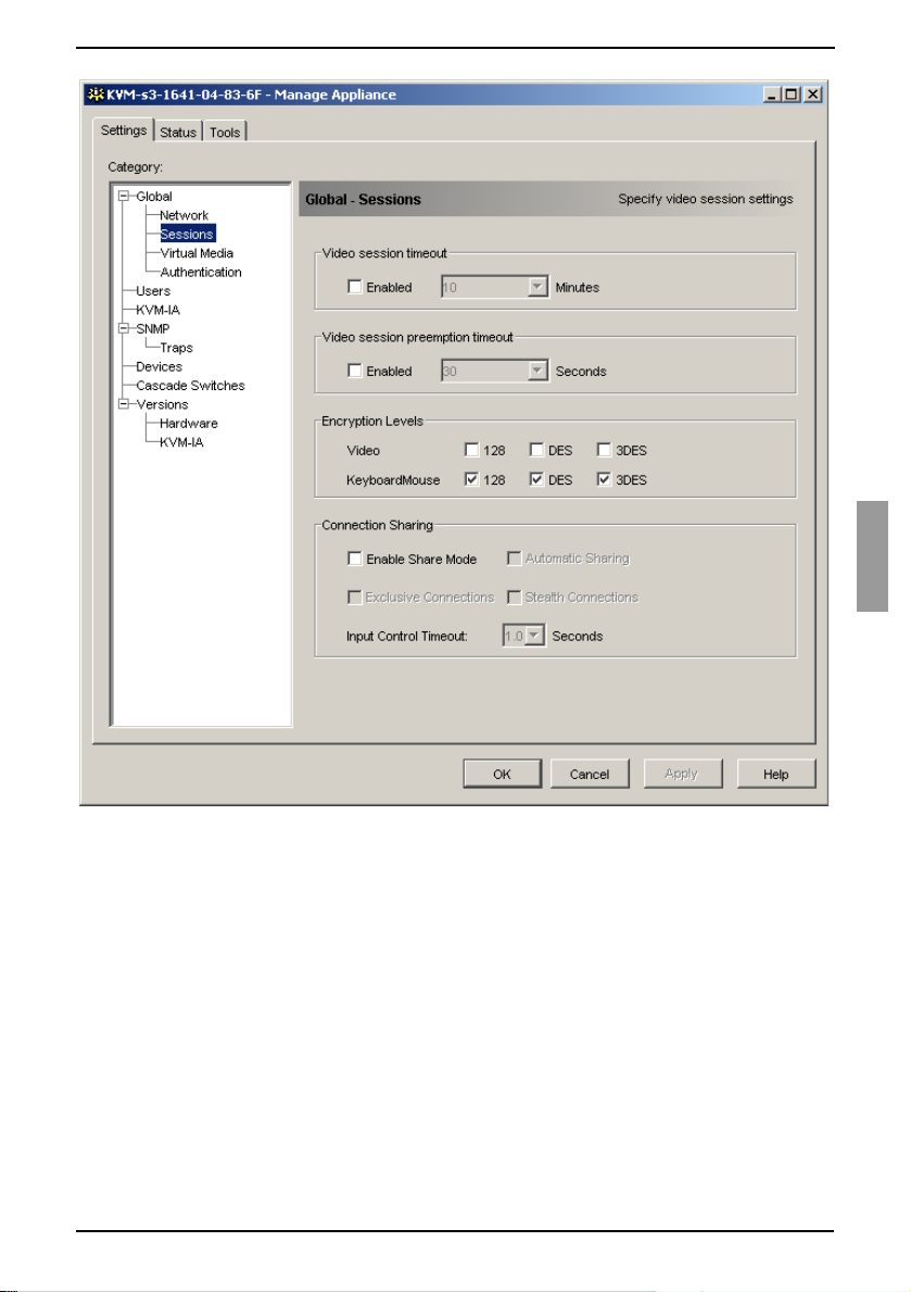
Appliance Management Panel Configuring Global Session settings
Figure 18: AMP Global Sessions settings
In the Video Session Timeout area, select or clear the Enabled check box. If you
enable the video session time-out, specify the time-out value in the Minutes list.
This value indicates the number of minutes the appliance will wait to close an
inactive video session. You can select a value from the list or enter a value in the
range of 1 to 60 minutes.
In the Video session preemption timeout area, select or clear the Enabled check
box. If you enable the video session preemption timeout, specify the time-out value
in the Seconds list. This value indicates the number of seconds the appliance will
wait for a user to respond to a preemption warning. You can select a value from the
list or enter a value in the range of 5 to 120 seconds.
In the Encryption Levels area, select one or more levels of encryption to encode
keyboard and mouse data sent over a video session to the appliance. The highest
level enabled is used. Repeat this step for the Video encryption level. Video
590-590-609A
65
Page 76

Configuring Global Virtual Media settings Appliance Management Panel
encryption is optional, but at least one Keyboard/Mouse encryption level must
be selected.
In the Connection Sharing area, select sharing options as needed. If you select
Enable Share Mode, users can share KVM sessions for the same target device. If
you select Automatic Sharing, secondary users can share KVM sessions without
first requesting permission from the primary user. If you select Exclusvie
Connections, primary users can designate a KVM session as exclusive (exclusive
sessions cannot be shared). Selecting Stealth Connections enables
administrators to monitor a target device undetected. You can also specify in the
Input Control Timeout field the number of seconds the appliance will wait for
activity before transferring keyboard and mouse control from the primary user to the
secondary user.
Video Session Time-out, Video Encryption and Connection Sharing are not
available for the KVM s2-1611 appliance (and will not be displayed).
Complete one of the following steps:
•Click Apply to save any changes without exiting the AMP.
-or-
•Click OK to save any changes and exit the AMP.
-or-
•Click Cancel to exit the AMP without saving any changes.
5.2.3 Configuring Global Virtual Media settings
Use the Global - Virtual Media subcategory to specify the settings for Virtual Media
sessions.
Available only for the KVM s3-1621 and KVM s3-1641 appliances.
Click the Settings tab in the AMP.
Select the Global - Virtual Media subcategory.
66
590-590-609A
Page 77

Appliance Management Panel Configuring Global Virtual Media settings
Figure 19: AMP Global Virtual Media settings
In the Session Control area, select or clear the check boxes as needed. If you
clear Lock to KVM Session, virtual media sessions can remain after the Video
Session that starts it closes. If you select Allow Reserved Sessions, then the
owner of the virtual media session can choose to prevent other users from
establishing a KVM session to the same target device. Also when the virtual media
session is reserved, the corresponding KVM session is not subject to inactivity
time-outs and cannot be preempted. If you select Read-Only Access, write access
to Virtual Media sessions is prevented.
In the Encryption Levels area, select zero or more levels of encryption to encode
Virtual Media data sent over a video session to the appliance. The highest level
enabled is used.
590-590-609A
67
Page 78

Configuring Global Authentication settings Appliance Management Panel
Complete one of the following steps:
•Click Apply to save any changes without exiting the AMP.
-or-
•Click OK to save any changes and exit the AMP.
-or-
•Click Cancel to exit the AMP without saving any changes.
5.2.4 Configuring Global Authentication settings
There are two types of user accounts: internal and external. Internal (local) user
accounts reside within the appliance itself, while external user accounts are stored on
an external authentication server. The Users category provides methods for managing
internal user accounts.
The Global - Authentication category specifies the type and order of any
authentication methods used. If a method fails or is unavailable, the software uses the
next enabled authentication method.
Local authentication is always available as the primary or backup authentication
method, and cannot be disabled.
LDAP is supported by the KVM s2-0411, KVM s3-1621, and
KVM s3-1641 appliances.
5.2.4.1 Changing authentication settings
Click the Settings tab in the AMP.
Select the Global - Authentication subcategory.
68
590-590-609A
Page 79

Appliance Management Panel Configuring Global Authentication settings
Figure 20: AMP Global Authentication settings
To specify an authentication method, select the check box next to the method in the
Authentication Settings area.
When you specify more than one authentication method, you can control the order
in which they are tried by changing the order in the list. Select a method and then
click one of the Reorder Authentication Methods buttons. Click the up button to
shift the selected method up; click the down button to shift the selected
method down.
You can choose to use LDAP for authentication only, not for authorization, when
using the local user database for authorization. Select or clear the check box next
to Use LDAP for Authentication Only as needed.
You can choose to validate the values entered by the user for LDAP-related fields in
either the Search Parameters or Query Parameters tab. Select or clear the check
box next to LDAP Syntax Validation as needed.
590-590-609A
69
Page 80

Configuring LDAP Appliance Management Panel
Complete one of the following steps:
•Click Apply to save any changes without exiting the AMP.
-or-
•Click OK to save any changes and exit the AMP.
-or-
•Click Cancel to exit the AMP without saving any changes.
For example, if LDAP is enabled as the first authentication method, followed by Local,
the following process occurs:
• The appliance attempts LDAP authentication by querying its Management
Information Base (MIB) to obtain the LDAP parameters specified in the LDAP
Parameters field, which are then sent to and verified on the LDAP directory
service.
• If LDAP authentication fails, the appliance attempts local authentication.
• If local authentication also fails, an error code is returned for the highest priority
authentication method attempted, which in this case is LDAP.
5.3 Configuring LDAP
LDAP is a vendor-independent protocol standard used for accessing, querying, and
updating a directory using TCP/IP. Based on the X.500 Directory Services model, LDAP
is a global directory structure that supports strong security features including
authentication, privacy, and integrity.
5.3.1 LDAP authentication configuration parameters
If individual user accounts are stored on an LDAP-enabled directory service, such as
Active Directory, you can use the directory service to authenticate users.
The default values given for the LDAP search and query parameters are defined for use
with Active Directory.
The settings made in the Global - Authentication subcategory of the AMP Settings
tab let you configure your authentication configuration parameters. The software sends
the KVM s3 Client user name, password, and other information to the appliance, which
then determines whether the KVM s3 Client user has permission to view or change
configuration parameters for the appliance in the AMP.
Important: Unless otherwise specified, the LDAP default values should be used unless
Active Directory has been reconfigured. Modifying the default values may cause LDAP
authentication server communication errors.
70
590-590-609A
Page 81

Appliance Management Panel LDAP server parameters
5.3.2 LDAP server parameters
Clicking the Server Parameters tab displays the parameters that define LDAP server
connection information.
Figure 21: LDAP Server Parameters tab
The IP Address fields specify the host names or IP addresses of the primary and
secondary LDAP servers. These values cannot be loopback addresses or all zeros.
The second LDAP server is optional.
The Port ID fields specify the User Datagram Protocol (UDP) port numbers that are
used to communicate with the LDAP servers. The default value is 389 for non-secure
LDAP and 636 for secure LDAP. The default Port ID is automatically entered by the
software when an access type is specified.
The Access Type radio buttons specify how a query is sent to each LDAP server. Click
LDAP to send a query as clear text (non-secure LDAP) or LDAPS to send a query using
a Secure Socket Layer (SSL) (secure LDAP).
590-590-609A
71
Page 82

LDAP search parameters Appliance Management Panel
When using LDAP, all user names, passwords, etc. sent between an
appliance and LDAP server are sent as non-secure, clear text. Use LDAPS
for secure, encrypted communication between an appliance and
LDAP server.
5.3.3 LDAP search parameters
Clicking the Search Parameters tab displays the parameters used when searching for
LDAP directory service users.
Figure 22: LDAP Search Parameters tab
Use the Search DN field to define an administrator-level user that the appliance uses to
log into the directory service. Once the appliance is authenticated, the directory service
grants it access to the directory to perform the user authentication queries specified on
the Query Parameters tab. The default values are
dc=yourDomainName,
72
and
dc=com
and may be modified. For example, to define an
cn=Administrator, cn=Users
590-590-609A
,
Page 83

Appliance Management Panel LDAP Query Parameters
administrator Distinguished Name (DN) for test.view.com, type
cn=Users, dc=test, dc=view
service has been configured to enable anonymous search, which is not the default.
Each Search DN value must be separated by a comma. The Search Password field is
used to authenticate the administrator or user specified in the Search DN field.
Use the Search Base field to define a starting point from which LDAP searches begin.
The default values are
example, to define a search base for test.com, type
Base value must be separated by a comma.
The UID Mask field specifies the search criteria for User ID searches of LDAP target
devices. The format should be in the form
sAMAccountName=%1
required for LDAP searches.
, and
dc=com
dc=yourDomainName, dc=com
. This is a required field unless the directory
, and may be modified. For
dc=test, dc=com
<name>=<%1>
, which is correct for use with Active Directory. This field is
cn=Administrator
. Each Search
. The default value is
,
5.3.4 LDAP Query Parameters
Clicking the Query Parameters tab displays the parameters used when performing
user authentication queries.
The appliance performs two different types of queries. Query mode (appliance) is used
to authenticate administrators attempting to access the appliance itself. Query mode
(device) is used to authenticate users that are attempting to access attached target
devices.
Additionally, each type of query has three modes that utilize certain types of information
to determine whether or not a KVM s3 Client user has access to an appliance or
connected target devices.
590-590-609A
73
Page 84

LDAP Query Parameters Appliance Management Panel
Figure 23: LDAP Query Parameters tab
You can configure the following settings in the Query Parameters tab:
•The Query Mode (Appliance) parameters determine whether or not a KVM s3
Client user has access to the appliance.
•The Query Mode (Device) parameters determine whether or not a KVM s3 Client
user has user access to target devices connected to an appliance. The user does
not have access to the appliance.
•The Group Container, Group Container Mask, and Target Mask fields are only
used for group query modes and are required when performing an appliance query.
•The Group Container field specifies the organizational unit (ou) created in Active
Directory by the administrator as the location for group objects. Group objects are
Active Directory objects that can contain users, computers, contacts, and other
groups. Group Container is used when Query Mode is set to Group. Each group
object, in turn, is assigned members to associate with a particular access level for
member objects (users, appliances, and target devices). The access level
74
590-590-609A
Page 85

Appliance Management Panel Appliance and device query modes
associated with a group is configured by setting the value of an attribute in the
group object. For example, if the Notes property in the group object is used to
implement the access control attribute, the Access Control Attribute field in the
info
Query Parameters tab should be set to
User Admin causes the members of that group to have user administration access
to the appliances and target devices that are also members of that same group.
The Notes property is used to implement the access control attribute. The value of
the Notes property, available in group and user objects shown in Active Directory
Users and Computers (ADUC), is stored internally in the directory, in the value of
info
attribute. ADUC is a Microsoft Management Console snap-in for configuring
the
Active Directory. It is started by selecting Start - Programs - Administrative Tools
- Active Directory Users and Computers. This tool is used to create, configure
and delete objects such as users, computers and groups. See Figure 24 on page
76 for more information.
•The Group Container Mask field defines the object type of the Group Container,
which is normally an organizational unit. The default value is “ou=%1”.
•The Target Mask field defines a search filter for the target device. The default value
is “cn=%1”.
•The Access Control Attribute field specifies the name of the attribute that are
used when the query modes are set to Attribute. The default value is
. Setting the Notes property to KVM
info
.
5.3.5 Appliance and device query modes
One of three different modes can each be used for Query Mode (Appliance) and
Query Mode (Device):
• Basic – A user name and password query for the KVM s3 Client user is made to
the directory service. If they are verified, the KVM s3 Client user is given
administrator access to the appliance and any attached target devices for Query
Mode (Appliance), or to any selected target device for Query Mode (Device).
• Attribute – A user name, password, and Access Control Attribute query for the
appliance user is made to the directory service. The Access Control Attribute is
read from the user object (the user account) in Active Directory.
If the value “KVM Appliance Admin” is found, the KVM s3 Client user is given
appliance administrator access to the appliance and any attached target devices for
Query Mode (Appliance), or to any selected target device for Query Mode
(Device). If the value “KVM User Admin” is found, the KVM s3 Client user is given
User administrator access to the appliance and attached target devices for Query
Mode (Appliance), or to any selected target device for Query Mode (Device).
The following are examples showing how the KVM Appliance Admin and KVM
User Admin attribute modes are defined in Active Directory for a user named John
Smith, stored in the ADUC. You can access the ADUC by selecting Start Programs - Administrative Tools - Active Directory Users and Computers.
590-590-609A
75
Page 86

Appliance and device query modes Appliance Management Panel
Figure 24: Active Directory - KVM user
• Group – A user name, password, and group query is made to the directory service
for an appliance and attached target devices when using Query Mode
(Appliance), or for a selected target device when using Query Mode (Device). If a
group is found containing the user and the appliance name, the KVM s3 Client user
is given access to the appliance or attached target devices, depending on the group
contents, when using Query Mode (Appliance). If a group is found containing the
user and target device IDs, the KVM s3 Client user is given access to the selected
target device connected to the appliance when using Query Mode (Device).
Groups can be nested to a maximum of 16 levels in depth. Use nesting to create
groups within other groups. For example, you may have a top-level group named
Computers that contains a member named R&D, which is a group. The R&D group
may contain a member named Domestic, which is a group, and so on.
The following is an example of groups defined in Active Directory.
76
590-590-609A
Page 87

Appliance Management Panel Setting up Active Directory for performing queries
Figure 25: Active Directory - Define groups
5.3.6 Setting up Active Directory for performing queries
Before you can use any of the querying modes for units, you must first make changes to
Active Directory so that the selected querying mode can assign the applicable
authorization level for the KVM s3 Client user.
To set up group queries, complete the following steps:
Log into Windows with administrator privileges.
Open Active Directory software.
Create an organizational unit to be used as a group container.
Create an object in Active Directory with a name identical to the switching system
name for querying appliances (specified in the Name field in the SNMP category of
the AMP), or identical to the names of the attached target devices for querying
target devices (specified in the Devices category of the AMP). The name must
match exactly, including case.
590-590-609A
77
Page 88

Managing local user accounts Appliance Management Panel
The appliance names and target device names used for group queries are stored in
the appliance. The appliance name and target device names specified in the SNMP
and Devices categories of the AMP must identically match the object names in
Active Directory. Each appliance name and target device name may be comprised
of any combination of upper-case and lower-case letters (a-z, A-Z), digits (0-9) and
hyphens (-). You cannot use spaces and periods (.) or create a name that consists
entirely of digits. These are Active Directory constraints.
Create one or more groups under the group container organizational unit.
Add the user names and target device and appliance to the groups you created in
step 5.
Specify the value of any attribute being used to implement the access control
info
attribute. For example, if you are using
Attribute field and using the Notes property in the group object to implement the
access control attribute, the value of the Notes attribute in Active Directory may be
set to one of the three available access levels (KVM User, KVM User Admin, or
KVM Appliance Admin) for the group object. The members of the group may then
access the appliances and target devices at the specified access level.
as the attribute in the Access Control
5.4 Managing local user accounts
The Users category lists user names in the appliance user database and their access
levels. You can add, modify, or delete a user account from this category. The security
lock-out feature is also controlled from this category.
The fields in this category are disabled if LDAP is being used for both Authentication
and Authorization. If LDAP is being used only for Authentication, then users can be
added and modified in this category, but only to set the access control lists for the users
(the password fields are disabled in this mode).
5.4.1 Access levels
You can assign users one of three access levels: user, user administrator, or appliance
administrator. Use the user access level to assign individual target device access rights
to a user.
Table 7 on page 79 indicates the types of appliance operations that can be performed in
the three access levels.
78
590-590-609A
Page 89

Appliance Management Panel Access levels
Operations Appliance
administrator
Preempt other users All Equal and lesser No
Set network and global
values
Reboot and upgrade
firmware
Manage user accounts Yes Yes No
Monitor target device
status
Access target devices Yes Yes Assigned by Admin
Table 7: Appliance access levels
5.4.1.1 Adding or modifying a user
Click the Settings tab in the AMP.
Select the Users category.
Yes No No
Yes No No
Yes Yes No
User
administrator
User
Figure 26: AMP User settings
590-590-609A
79
Page 90

Access levels Appliance Management Panel
Complete one of the following steps:
• To add a new user, click the Add button. The Add User window opens.
-or-
• To modify a user, select a user name and click the Modify button. The Modify
User window opens.
Complete one of the following steps:
• When adding a user, enter the user name and password to assign to the user
and then verify the password by typing it in the Verify Password field.
-or-
• When modifying a user, change the password, if needed.
When Use LDAP for Authentication only is selected in the Global -
Authentication category, the password field is disabled and only the access rights
of the user are used.
Select the needed access level for this user from the pull-down menu. If you select
the User option, the Access Rights button is visible.
a. To select individual target device access for the user, click the Access Rights
button. The User Access Rights window opens.
b. To add access to target devices, select one or more target devices in the left
(No access to) column. Click the Add button.
c. To remove access to target devices, select one or more target devices in the
right (Allow access to) column. Click the Remove button.
d. Repeat steps b and c until the right (Allow access to) column represents the
applicable target device access for this user, and then click OK.
Complete one of the following steps:
•Click Apply to save any changes without exiting the AMP.
-or-
•Click OK to save any changes and exit the AMP.
-or-
•Click Cancel to exit the AMP without saving any changes.
5.4.1.2 Deleting a user
Click the Settings tab in the AMP.
Select the Users category.
Select the user or users to delete.
Click the Delete button. You are prompted to confirm the deletion.
Click Yes to confirm the deletion.
Complete one of the following steps:
•Click Apply to save any changes without exiting the AMP.
-or-
•Click OK to save any changes and exit the AMP.
-or-
•Click Cancel to exit the AMP without saving any changes.
80
590-590-609A
Page 91

Appliance Management Panel Locking and unlocking user accounts
Add, Modify and Delete user operations may be combined and saved at the
same time by pressing the Apply or OK buttons on the AMP when done with
the changes.
5.4.2 Locking and unlocking user accounts
When the security lock-out feature is enabled, and a user enters an invalid password
five consecutive times, that user account is disabled for a specified number of hours, or
until it is unlocked or the appliance is rebooted. If a locked-out user tries to log in during
the lock-out period, an error message is displayed. A closed-lock icon is visible next to
the names of locked-out users on the AMP Users category. Security lock-out, when
enabled, applies to all local user accounts on the appliance, but not to LDAP users.
An appliance administrator can specify the lock-out period. A user administrator can
unlock only user accounts; an appliance administrator can unlock any type of account.
When the security lock-out feature is disabled, no users are locked-out. Disabling
security lock-out has no effect on users who are already locked-out.
5.4.2.1 Enabling or disabling security lock-out
Click the Settings tab in the AMP.
Select the Users category.
Complete one of the following steps:
• Select the Enable Lock-outs check box. Enter the number of hours (1 to 99) in
the lock-out period in the Duration field.
-or-
• Clear the Enable Lock-outs check box.
Complete one of the following steps:
•Click Apply to save any changes without exiting the AMP.
-or-
•Click OK to save any changes and exit the AMP.
-or-
•Click Cancel to exit the AMP without saving any changes.
5.4.2.2 Unlocking an account
Click the Settings tab in the AMP.
Select the Users category.
Select the user to unlock.
Click the Unlock button.
Complete one of the following steps:
•Click Apply to save any changes without exiting the AMP.
-or-
•Click OK to save any changes and exit the AMP.
-or-
•Click Cancel to exit the AMP without saving any changes.
A locked-out user is unlocked if the appliance is rebooted or when the configured lockout duration expires.
590-590-609A
81
Page 92

Managing user sessions Appliance Management Panel
5.5 Managing user sessions
The Status tab displays information about currently active Video Viewer and virtual
media sessions. Each line of session information includes:
• The status of the session. A Locked icon is shown for KVM sessions that are locked
to virtual media sessions, and a Reserved icon is shown for reserved virtual media
sessions.
• The name of the user who is logged in to the session.
• The length of time this session has been active, in the form hours:minutes:seconds.
If the session has been active for more than 24 hours, the number of days precedes
the other time information. For example, a session that has been active for two
days, three hours, seven minutes, and 52 seconds shows 2d 3:07:52.
• The type of session, including both virtual media sessions and KVM sessions. The
session status also displays the video session type, such as KVM (Stealth). For
more information on session types see Table 4.1.
• The name of the target device to which this session is connected. If the session is
connected to a KVM-IA with no target device name specified in the database, the
KVM-IA EID is listed. If the session is connected to a cascade switch, the KVM-IA
EID, target device name, and channel number are listed.
• The IP address of the remote client connected to this session.
.
Figure 27: AMP Status tab
82
590-590-609A
Page 93

Appliance Management Panel Viewing and changing KVM-IA settings
5.5.0.1 Disconnecting a user session
Click the Status tab in the AMP.
Select one or more users sessions to disconnect. Use the Shift or Ctrl key to select
multiple user sessions.
Click the Disconnect Session button. A message prompts you to confirm the
disconnect request.
Complete one of the following steps:
•Click Yes to disconnect the user sessions.
-or-
•Click No to cancel the disconnect.
5.6 Viewing and changing KVM-IA settings
The Conversion Options category displays information about each KVM Intelligent
Adapter, including its input port number, ID, type, language, and status. The possible
status values are:
• Green circle = the KVM-IA is online
• Yellow circle = the KVM-IA is upgrading
• Red X = the KVM-IA is offline
5.6.1 Displaying KVM-IA information
Click the Settings tab in the AMP.
Select the KVM-IA category.
Figure 28: AMP KVM-IA settings
590-590-609A
83
Page 94

Removing offline KVM-IAs from the list Appliance Management Panel
5.6.2 Removing offline KVM-IAs from the list
Click the Settings tab in the AMP.
Select the KVM-IAs category.
Click Clear Offline.
5.6.3 Changing the language reported by USB and Sun
KVM-IAs
Click the Settings tab in the AMP.
Select the KVM-IAs category.
Click Language.
Select the keyboard layout from the list.
Complete one of the following steps:
•Click OK to select the keyboard layout.
-or-
•Click Cancel to return to the AMP without changing the language.
Complete one of the following steps:
•Click Apply to save any changes without exiting the AMP.
-or-
•Click OK to save any changes and exit the AMP.
-or-
•Click Cancel to exit the AMP without saving any changes.
All USB and Sun KVM-IAs report in the new language.
5.7 Using SNMP
The SNMP category specifies general SNMP configuration information. The SNMP Traps subcategory indicates which traps are enabled and disabled.
SNMP (Simple Network Management Protocol) is a protocol used to communicate
management information between network management applications and appliances.
SNMP managers (such as Tivoli and HP OpenView) can communicate with the
appliance by accessing MIB-II (Management Information Base) and the public portion of
the enterprise MIB. MIB-II is a standard MIB that many SNMP managers support. You
can
• Enable or disable SNMP operations.
• Enter appliance information and community strings.
• Indicate which computers can manage the appliance. If you enter one or more
allowable managers, only those IP addresses can monitor the appliance using
SNMP. If you do not enter any allowable managers, then the appliance can be
monitored using SNMP from any IP address.
• Indicate which computers receive SNMP traps from the appliance. If you do not
specify any trap destinations, no traps are sent.
When you enable SNMP, the unit responds to SNMP requests over UDP port 161. Port
161 is the standard UDP port used to send and receive SNMP messages.
84
590-590-609A
Page 95

Appliance Management Panel Configuring general SNMP settings
The AMP uses SNMP within a secure tunnel to manage appliances. For this reason,
UDP port 161 does not need to be exposed on firewalls. You must expose UDP port 161
to monitor appliances using third party SNMP-based management software.
5.7.1 Configuring general SNMP settings
Click the Settings tab in the AMP.
Select the SNMP category.
Figure 29: AMP SNMP category
Select or clear the Enable SNMP check box.
In the Name field, enter the 0 to 255 character fully qualified domain name of the
appliance. In the Contact field, enter 0 to 255 characters of contact information.
In the Community Names area, enter the 1 to 64 character Read, Write, and Trap
community names. These specify the community strings that must be used in
SNMP actions. The Read and Write strings apply only to SNMP over UDP port 161
and act as passwords that protect access to the appliance.
In the Allowable Managers area, specify up to four SNMP management entities to
monitor the appliance, or leave this area blank to let any computer to monitor the
appliance.
To add an allowable manager, complete the following steps:
590-590-609A
85
Page 96

Configuring general SNMP settings Appliance Management Panel
a. Click the Add button. The Allowable Manager window opens.
b. Enter the IP address of the management computer.
c. Click OK to add the management computer.
To modify an allowable manager, complete the following steps:
a. Select an entry in the Allowable Managers list, then click the Modify button.
The Allowable Manager window opens.
b. Modify the entry as needed.
c. Click OK to save the change.
To delete an allowable manager, complete the following steps:
a. Select one or more entries in the Allowable Mangers list, then click the Delete
button. You are prompted to confirm the deletion.
b. Click Yes to confirm the deletion.
In the Trap Destinations area, specify up to four destinations to which this
appliance sends traps.
To add a trap destination, complete the following steps:
a. Click the Add button. The Trap Destination window opens.
b. Enter the IP address of the trap destination.
c. Click OK to add the trap destination.
To modify a trap destination, complete the following steps:
a. Select one or more entries in the Trap Destinations list, then click the Modify
button. The Trap Destination window opens.
b. Modify the entry as needed.
c. Click OK to save the change.
To delete a trap destination, complete the following steps:
a. Select an entry in the Trap Destinations list, then click the Delete button. You
are prompted to confirm the deletion.
b. Click Yes to confirm the deletion.
Complete one of the following steps:
•Click Apply to save any changes without exiting the AMP.
-or-
•Click OK to save any changes and exit the AMP.
-or-
•Click Cancel to exit the AMP without saving any changes.
If you clicked Apply or OK, you are prompted to confirm a reboot. The new settings
are not used until the appliance reboots. Complete one of the following steps:
•Click Yes to reboot the appliance. The AMP displays the status and indicates
when the reboot is complete.
-or-
•Click No to reboot at a later time.
86
590-590-609A
Page 97

Appliance Management Panel Managing SNMP traps
5.7.2 Managing SNMP traps
An SNMP trap is a notification sent by the appliance to a management computer,
indicating that an event has occurred in the appliance that can require further attention.
You can specify which individual SNMP traps are sent to the management computers
by selecting the corresponding check boxes, or you can enable or disable all traps. All of
the FSC KVM appliances have enterprise traps. To interpret these traps correctly,
download the corresponding trap MIB from the Fujitsu Siemens Web site.
5.7.2.1 Enabling or disabling SNMP traps
Click the Settings tab in the AMP.
Select the SNMP - Traps subcategory. A list of traps is displayed. Traps that are
currently enabled are selected; disabled traps are not selected.
Figure 30: AMP SNMP - Traps subcategory
Complete one of the following steps:
• Select or clear the individual trap check boxes.
590-590-609A
87
Page 98

Viewing target device connection information Appliance Management Panel
-or-
• To enable all traps, click the Enable All button.
-or-
• To disable all traps, click the Disable All button.
Complete one of the following steps:
•Click Apply to save any changes without exiting the AMP.
-or-
•Click OK to save any changes and exit the AMP.
-or-
•Click Cancel to exit the AMP without saving any changes.
5.8 Viewing target device connection
information
The Devices category displays connection information for each target device, as
follows:
• KVM-IA - The display shows the EID of the KVM-IA.
• Cascaded switch - The display shows the cascade switch and all of its channels.
• No device connection - The display indicates “None”.
When you select the Devices category for the first time, the AMP retrieves the target
devices that exist in the software database as well as information on how the target
devices are connected to the selected appliance. The Connections column lists the
current target device connection. This can be to either a KVM-IA or a cascade switch. If
connected to a KVM-IA, the KVM-IA EID is visible in the Connections column. If
connected to a cascade switch, the cascade switch and all of its channels are visible. If
no unit is currently connected to the path, then this field displays “None”.
Clicking on a hyperlink of a target device entry opens the Video Viewer.
You can resynchronize the database on the computer with the database on the
appliance from this category. See Figure 31 on page 89.
5.8.1 Modifying target device names
The Devices category can be used to modify the target device name on both the
appliance and in the client database.
Click the Settings tab in the AMP.
Select the Devices category.
88
590-590-609A
Page 99

Appliance Management Panel Modifying target device names
Figure 31: AMP Settings - Devices
Select the target device from the list that you want to modify. You can only modify
one target remote console switch at a time.
Click Modify.
The pop-up window lists the current name of the target device as stored in both the
appliance and the client database (not necessarily the same).
Type the new name of the target device in the New Name field.
Complete one of the following steps:
•Click OK to change the target device name.
-or-
•Click Cancel to keep the target device name as is.
Repeat the steps 3 through 7 for each target device name that you want to change.
590-590-609A
89
Page 100

Resynchronizing the target device list Appliance Management Panel
Complete one of the following steps:
•Click Apply to save any changes without exiting the AMP.
-or-
•Click OK to save any changes and exit the AMP.
-or-
•Click Cancel to exit the AMP without saving any changes.
5.8.2 Resynchronizing the target device list
You might need to resynchronize the target device list if the local user has changed
target device names on the appliance using the OSCAR interface or if KVM-IAs have
been added or moved.
Prior to starting the resynchronization process, a warning message indicates that the
database will be updated to match the current configuration in the appliance. This
warning contains a check box that indicates whether offline KVM-IAs will be included.
When enabled, target devices associated with KVM-IAs that are offline are included.
When disabled, offline KVM-IAs are not included and any existing target devices
associated with them in the database are removed.
This procedure only resynchronizes your own KVM s3 Client client. To keep databases
consistent when you have multiple computers using the software, save your
resynchronized local database and restore it to the other computers.
Click the Settings tab in the AMP.
Select the Devices category.
Click the Resync button. The Resync Wizard opens. Click Next.
A warning message indicates that the database will be updated to match the
current configuration in the appliance. Select or clear the Include Offline KVM-IAs
check box. Click Next.
A Polling Appliance message is displayed with a progress bar indicating that
appliance information is being retrieved.
Complete one of the following steps:
• If no changes were detected in the appliance, a completion window opens with
this information. Click OK.
-or-
• If target device changes were detected, the Detected Changes window opens.
Click Next to update the database.
-or-
• If a cascade switch was detected, the Enter Cascaded Switch Information win-
dow opens. Select the type of cascade switch connected to the appliance from
the pull-down menu. If the type you are looking for is not available, you can add
it using the Add button. For more information, see “Configuring cascade switch
connections” on page 91. Click Next.
The completion window opens. Click Finish to exit.
90
590-590-609A
 Loading...