

Page 1

control
User Guide
KVM series2-1611
Keyboard/Video/Mouse Switch
English
2
Page 2

Page 3

KVM series2-1611
Installer/User Guide
Edition October 2005
Page 4

Comments... Suggestions... Corrections
The User Documentation Department would like to know your
opinion of this manual. Your feedback helps us optimize our
documentation to suit your individual needs.
Fax forms for sending us your comments are included in the
back of the manual.
There you will also nd the addresses of the relevant User
Documentation Department.
Certied documentation
according to DIN EN ISO 9001:2000
To ensure a consistently high quality standard and user-friendliness, this documentation was created to meet the regulations of
a quality management system which complies with the requirements of the standard DIN EN ISO 9001:2000.
Copyright and Trademarks
Copyright © 2005 Fujitsu Siemens Computers GmbH.
All rights reserved.
Delivery subject to availability; right of technical modications reserved.
All hardware and software names used are trademarks of their respective manufacturers.
This manual is printed on
paper treated with
chlorine-free bleach.
Page 5

Contents
1 Preface. . . . . . . . . . . . . . . . . . . . . . . . . . . . . . . . . . . . . . . . . . . . . . . . . 1
1.2 Summary of contents . . . . . . . . . . . . . . . . . . . . . . . . . . . . . . . . . . . . . . 2
1.3 Notational Conventions . . . . . . . . . . . . . . . . . . . . . . . . . . . . . . . . . . . . 2
2 Safety notes . . . . . . . . . . . . . . . . . . . . . . . . . . . . . . . . . . . . . . . . . . . . 3
2.1 Radio frequency information . . . . . . . . . . . . . . . . . . . . . . . . . . . . . . . . 3
2.2 Precautions and rack mount safety . . . . . . . . . . . . . . . . . . . . . . . . . . . 4
3 KVM series2-1611. . . . . . . . . . . . . . . . . . . . . . . . . . . . . . . . . . . . . . . . 5
3.1 Preinstallation. . . . . . . . . . . . . . . . . . . . . . . . . . . . . . . . . . . . . . . . . . . . 5
3.1.1 Getting started . . . . . . . . . . . . . . . . . . . . . . . . . . . . . . . . . . . . . . . . . . . 5
3.1.1.1 Supplied with the KVM series2-1611 . . . . . . . . . . . . . . . . . . . . . . . . . . 5
3.1.1.2 Additional items needed . . . . . . . . . . . . . . . . . . . . . . . . . . . . . . . . . . . . 5
3.1.4 Setting up your network . . . . . . . . . . . . . . . . . . . . . . . . . . . . . . . . . . . . 5
3.1.3 Rack mounting your appliance . . . . . . . . . . . . . . . . . . . . . . . . . . . . . . . 6
3.1.3.1 Installing the rack mount brackets . . . . . . . . . . . . . . . . . . . . . . . . . . . . 6
3.2 KVM series2-1611 hardware . . . . . . . . . . . . . . . . . . . . . . . . . . . . . . . . 7
3.2.1 Power ratings . . . . . . . . . . . . . . . . . . . . . . . . . . . . . . . . . . . . . . . . . . . . 8
3.2.2 Dimensions and environmental conditions. . . . . . . . . . . . . . . . . . . . . . 8
3.2.3 Standards . . . . . . . . . . . . . . . . . . . . . . . . . . . . . . . . . . . . . . . . . . . . . . . 8
3.3 Installing the KVM series2-1611. . . . . . . . . . . . . . . . . . . . . . . . . . . . . . 9
3.3.1 Installing the KVM series2-1611 hardware. . . . . . . . . . . . . . . . . . . . . 10
3.3.2 Configuring the KVM series2-1611 hardware. . . . . . . . . . . . . . . . . . . 10
3.3.3 Adjusting the mouse acceleration. . . . . . . . . . . . . . . . . . . . . . . . . . . . 11
3.3.3.1 Adjusting the mouse using Microsoft Windows NT® . . . . . . . . . . . . . 11
3.3.3.2 Adjusting the mouse using Microsoft Windows 2000/XP . . . . . . . . . . 11
3.3.3.3 Adjusting the mouse using Solaris . . . . . . . . . . . . . . . . . . . . . . . . . . . 11
3.3.4 Connecting a KVM s2-Adapter to each server . . . . . . . . . . . . . . . . . . 11
3.3.5 Adding a KVM switch . . . . . . . . . . . . . . . . . . . . . . . . . . . . . . . . . . . . . 12
3.3.6 Connecting/turning on your KVM s2-1611 . . . . . . . . . . . . . . . . . . . . . 13
590-332-501E
Page 6

Contents
3.4 Setting Up the KVM s2-1611/Client System. . . . . . . . . . . . . . . . . . . . 13
4 Operations. . . . . . . . . . . . . . . . . . . . . . . . . . . . . . . . . . . . . . . . . . . . . 15
4.1 Controlling Your System at the Analog Port. . . . . . . . . . . . . . . . . . . . 15
4.2 Viewing and Selecting Ports and Servers . . . . . . . . . . . . . . . . . . . . . 15
4.2.1 Accessing the Main dialog box. . . . . . . . . . . . . . . . . . . . . . . . . . . . . . 15
4.2.2 Viewing the status of your appliance . . . . . . . . . . . . . . . . . . . . . . . . . 16
4.2.3 Selecting servers . . . . . . . . . . . . . . . . . . . . . . . . . . . . . . . . . . . . . . . . 16
4.2.3.1 Selecting the previous server . . . . . . . . . . . . . . . . . . . . . . . . . . . . . . . 16
4.2.3.2 Disengaging the user from a server . . . . . . . . . . . . . . . . . . . . . . . . . . 16
4.2.4 Soft switching . . . . . . . . . . . . . . . . . . . . . . . . . . . . . . . . . . . . . . . . . . . 17
4.2.4.1 Configuring servers for soft switching. . . . . . . . . . . . . . . . . . . . . . . . . 17
4.2.4.2 Soft switching to a server . . . . . . . . . . . . . . . . . . . . . . . . . . . . . . . . . . 17
4.3 Navigating OSCAR. . . . . . . . . . . . . . . . . . . . . . . . . . . . . . . . . . . . . . . 17
4.4 Configuring OSCAR . . . . . . . . . . . . . . . . . . . . . . . . . . . . . . . . . . . . . . 19
4.4.1 Accessing the Setup menu. . . . . . . . . . . . . . . . . . . . . . . . . . . . . . . . . 19
4.4.2 Assigning server names . . . . . . . . . . . . . . . . . . . . . . . . . . . . . . . . . . . 20
4.4.2.1 Accessing the Names dialog box . . . . . . . . . . . . . . . . . . . . . . . . . . . 20
4.4.2.2 Assigning names to servers . . . . . . . . . . . . . . . . . . . . . . . . . . . . . . . 21
4.4.3 Assigning device types. . . . . . . . . . . . . . . . . . . . . . . . . . . . . . . . . . . . 21
4.4.3.1 Accessing the Devices dialog box . . . . . . . . . . . . . . . . . . . . . . . . . . . 22
4.4.3.2 Assigning a device type . . . . . . . . . . . . . . . . . . . . . . . . . . . . . . . . . . . 22
4.4.4 Changing the display behavior . . . . . . . . . . . . . . . . . . . . . . . . . . . . . . 23
4.4.4.1 Accessing the Menu dialog box . . . . . . . . . . . . . . . . . . . . . . . . . . . . . 23
4.4.4.2 Choosing the default display order of servers . . . . . . . . . . . . . . . . . . 24
4.4.4.3 Setting a Screen Delay Time for OSCAR. . . . . . . . . . . . . . . . . . . . . . 24
4.4.5 Controlling the status flag. . . . . . . . . . . . . . . . . . . . . . . . . . . . . . . . . . 24
4.4.5.1 Accessing the Flag dialog box . . . . . . . . . . . . . . . . . . . . . . . . . . . . . . 25
4.4.5.2 Determining how the status flag is displayed . . . . . . . . . . . . . . . . . . . 25
4.4.6 Setting console security . . . . . . . . . . . . . . . . . . . . . . . . . . . . . . . . . . . 26
4.4.6.1 Accessing the Security dialog box . . . . . . . . . . . . . . . . . . . . . . . . . . . 26
4.4.6.2 Setting or changing the password . . . . . . . . . . . . . . . . . . . . . . . . . . . 27
590-332-501E
Page 7

Contents
4.4.6.3 Password protecting your console . . . . . . . . . . . . . . . . . . . . . . . . . . . 27
4.4.6.4 Logging in to your console . . . . . . . . . . . . . . . . . . . . . . . . . . . . . . . . . 28
4.4.6.5 Removing password protection from your console: . . . . . . . . . . . . . . 28
4.4.6.6 Enabling the screen saver mode with no password protection . . . . . 28
4.4.6.7 Exiting the screen saver mode . . . . . . . . . . . . . . . . . . . . . . . . . . . . . . 29
4.4.6.8 Turning off the screen saver. . . . . . . . . . . . . . . . . . . . . . . . . . . . . . . . 29
4.4.6.9 Immediately turning on the screen saver . . . . . . . . . . . . . . . . . . . . . . 29
4.5 Viewing/Disconnecting User Connections . . . . . . . . . . . . . . . . . . . . . 29
4.5.1 Viewing current user connections. . . . . . . . . . . . . . . . . . . . . . . . . . . . 29
4.5.1.1 Disconnecting a user . . . . . . . . . . . . . . . . . . . . . . . . . . . . . . . . . . . . . 29
4.6 Resetting Your Keyboard and Mouse. . . . . . . . . . . . . . . . . . . . . . . . . 30
4.6.1 Resetting the mouse and keyboard values . . . . . . . . . . . . . . . . . . . . 30
4.7 Displaying Version Information. . . . . . . . . . . . . . . . . . . . . . . . . . . . . . 30
4.8 Scanning Your System. . . . . . . . . . . . . . . . . . . . . . . . . . . . . . . . . . . . 32
4.8.1 Adding servers to the scan list . . . . . . . . . . . . . . . . . . . . . . . . . . . . . . 33
4.8.2 Removing a server from the scan list . . . . . . . . . . . . . . . . . . . . . . . . . 34
4.8.3 Starting the scan mode. . . . . . . . . . . . . . . . . . . . . . . . . . . . . . . . . . . . 34
4.8.4 Cancelling scan mode . . . . . . . . . . . . . . . . . . . . . . . . . . . . . . . . . . . . 35
4.9 Broadcasting to Servers . . . . . . . . . . . . . . . . . . . . . . . . . . . . . . . . . . . 35
4.9.1 Accessing the Broadcast dialog box. . . . . . . . . . . . . . . . . . . . . . . . . . 35
4.9.1.1 Broadcasting to selected servers: . . . . . . . . . . . . . . . . . . . . . . . . . . . 36
4.9.1.2 Turning broadcasting off. . . . . . . . . . . . . . . . . . . . . . . . . . . . . . . . . . . 36
4.10 Terminal Operations . . . . . . . . . . . . . . . . . . . . . . . . . . . . . . . . . . . . . 36
4.10.1 Configuring the Terminal menu . . . . . . . . . . . . . . . . . . . . . . . . . . . . . 36
4.10.1.1 Accessing the Terminal menu . . . . . . . . . . . . . . . . . . . . . . . . . . . . . . 37
4.10.2 Network Configuration . . . . . . . . . . . . . . . . . . . . . . . . . . . . . . . . . . . . 37
4.10.2.1 Firmware Management. . . . . . . . . . . . . . . . . . . . . . . . . . . . . . . . . . . . 37
4.10.2.2 Enable Debug Messages . . . . . . . . . . . . . . . . . . . . . . . . . . . . . . . . . . 37
4.10.2.3 Set/Change Password . . . . . . . . . . . . . . . . . . . . . . . . . . . . . . . . . . . . 37
4.10.2.3.1 Activating security. . . . . . . . . . . . . . . . . . . . . . . . . . . . . . . . . . . . . . . 38
4.10.2.3.2 Changing the password . . . . . . . . . . . . . . . . . . . . . . . . . . . . . . . . . . 38
590-332-501E
Page 8

Contents
4.10.2.4 Exit . . . . . . . . . . . . . . . . . . . . . . . . . . . . . . . . . . . . . . . . . . . . . . . . . . . 39
5 Appendices . . . . . . . . . . . . . . . . . . . . . . . . . . . . . . . . . . . . . . . . . . . . 39
5.1 FLASH Upgrades . . . . . . . . . . . . . . . . . . . . . . . . . . . . . . . . . . . . . . . . 39
5.1.1 Uploading a new FLASH file. . . . . . . . . . . . . . . . . . . . . . . . . . . . . . . . 39
5.1.2 Upgrading the KVM s2-Adapter firmware. . . . . . . . . . . . . . . . . . . . . . 40
5.1.2.1 Simultaneously upgrading multiple KVM s2-Adapters . . . . . . . . . . . . 40
5.1.2.2 Upgrading KVM s2-Adapter firmware individually . . . . . . . . . . . . . . . 41
5.2 Sun Advanced Key Emulation . . . . . . . . . . . . . . . . . . . . . . . . . . . . . . 43
5.3 Technical Support. . . . . . . . . . . . . . . . . . . . . . . . . . . . . . . . . . . . . . . . 45
590-332-501E
Page 9

1 Preface
The Fujitsu Siemens KVM series2-1611 (KVM s2-1611) switches combine analog
and digital technology to provide exible, centralized control of data center servers. This solution delivers secure digital access and exible server management
from anywhere at any time.
Throughout the documentation you will see the word “appliance” used
generically to describe the KVM s2-1611 switch.
The KVM s2-1611 consists of a rack mountable keyboard, video and mouse
(KVM) switch congurable for analog or digital connectivity. Each KVM s2-1611
has 16 Fujitsu Siemens Rack Interface (RI) ports for connecting devices and operates over standard LAN connections. Access servers across a 100BaseT Ethernet
connection or directly through an analog port on the KVM s2-1611 for analog KVM
connectivity and administration. Video resolutions through the analog port can be
up to 1600 x 1280 with an end-to-end cable length of up to 15 meters (50 feet).
Digital users can achieve video resolution of up to 1280 x 1024 with a cable length
of up to 10 meters (32 feet) between the KVM s2-1611 and the server.
KVM series2-Adapter
The Fujitsu Siemens KVM series2-Adapters (KVM s2-Adapters) with CAT 5 design
dramatically reduce cable clutter, while providing optimal digital display resolution
and video settings. The built-in memory of the KVM s2-Adapter simplies
conguration by assigning and retaining unique server names or Electronic ID
(EID) numbers for each attached server. This integrated intelligence enhances
security and prevents unauthorized access to a server through cable manipulation.
The KVM s2-Adapter is powered directly from the server and provides Keep Alive
functionality even if the KVM s2-1611 is not powered.
Access via network connection
No special software or drivers are required on the attached computers. Digital
users access the KVM s2-1611 and all attached systems via Ethernet from a PC
running the KVM series2-Client (KVM s2-Client or Client) software. This software
resides on the user’s PC only. User PCs can be located anywhere a valid network
connection exists. The KVM s2-1611 can be congured on a separate network
from your data network, allowing access to your servers even if your applications
network is down.
Point and click control with KVM s2-Client software
The KVM s2-Client software is a cross-platform management application that
allows you to view and control the KVM s2-1611 and all attached servers.
The Client software provides secure authentication, data transfers and username/
590-332-501E 1
Page 10
Summary and Notational Conventions
password storage. By utilizing a browser interface for navigation with an intuitive
split-screen interface, this software provides you with a single point of access
for your entire system. From here, you can manage the KVM s2-1611, install a
new KVM s2-1611 or launch a video session to a system server. Multiple servers
can be accessed by one user; each additional computer’s video will appear in a
separate program window.
Throughout the documentation and KVM s2-Client user interface, you will
see the word “appliance” used generically to describe the
KVM s2-1611 switch.
Preface
1.2 Summary of contents
Safety notes
It is essential to read the following “Safety notes” chapter before
starting to work with the KVM s2-1611. That chapter contains essential
information for proper installation and handling of the
KVM s2-1611 device.
This manual describes how to install the KVM s2-1611 and explains how to congure and operate the appliance.
1.3 Notational Conventions
The following notational conventions are used in this manual:
Bold This indicates emphasis in the text.
Key This indicates keys or key combinations in continuous text.
Italics This indicates commands, le names, menu names and inputs in con-
tinuous text.
This indicates additional information and tips.
This indicates information, which if not heeded, may jeopardize your
Title
health, the functioning of your system or the security of your data.
This indicates a step that you have to perform.
- and • These characters symbolize itemized lists.
2 590-332-501E
Page 11
2 Safety notes
This chapter provides radio frequency and safety information for your appliance.
2.1 Radio frequency information
United States radio frequency information
Warning: Changes or modications to this unit not expressly approved
by the party responsible for compliance could void the user's authority
to operate the equipment.
This equipment has been tested and found to comply with the limits for a
Class A digital device, pursuant to Part 15 of the FCC Rules. These limits
are designed to provide reasonable protection against harmful interference
when the equipment is operated in a commercial environment. This
equipment generates, uses and can radiate radio frequency energy and,
if not installed and used in accordance with the instruction manual, may
cause harmful interference to radio communications. Operation of this
equipment in a residential area is likely to cause harmful interference in
which case the user will be required to correct the interference at his own
expense.
Canadian radio frequency information
This digital apparatus does not exceed the Class A limits for radio
noise emissions from digital apparatus set out in the Radio Interference
Regulations of the Canadian Department
of Communications.
Le présent appareil numérique n’émet pas de bruits radioélectriques
dépassant les limites applicables aux appareils numériques de la
classe A prescrites dans le Règlement sur le brouillage radioélectrique
édicté par le Ministère des Communications du Canada.
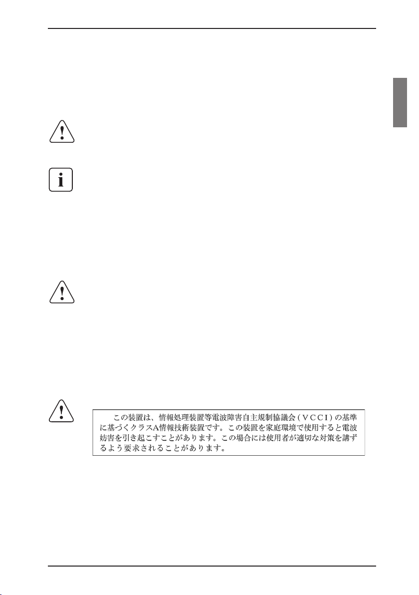
Japanese radio frequency information
590-332-501E 3
Page 12
2.2 Precautions and rack mount safety
Avoiding potential video and/or keyboard problems when using
the KVM s2-1611
• If the building has 3-phase AC power, ensure that the computer
and monitor are on the same phase. For best results, they should
be on the same circuit.
• Use only Fujitsu Siemens-supplied cable to connect computers and
KVM switches. Fujitsu Siemens warranties do not apply to damage
resulting from user-supplied cable.
Avoiding potentially fatal shock hazard and possible damage
to equipment
• Do not use a 2-wire extension cord in any of the Fujitsu Siemens
product congurations.
• Test AC outlets at the computer and monitor for proper polarity and
grounding.
• Use only with grounded outlets at both the computer and monitor.
When using an Uninterruptible Power Supply (UPS), power the
computer, the monitor and the appliance off the supply.
The AC inlet is the main disconnect.
Safety notesPrecautions and rack mount safety
Rack mount safety considerations
• Elevated Ambient Temperature: If installed in a closed rack assembly, the operation temperature of the rack environment may
be greater than room ambient. Use care not to exceed the rated
maximum ambient temperature of the unit.
• Reduced Air Flow: Installation of the equipment in a rack should be
such that the amount of airow required for safe operation of the
equipment is not compromised.
• Mechanical Loading: Mounting of the equipment in the rack should
be such that a hazardous condition is not achieved due to uneven
mechanical loading.
• Circuit Overloading: Consideration should be given to the
connection of the equipment to the supply circuit and the effect that
overloading of circuits might have on overcurrent protection and
supply wiring. Consider equipment nameplate ratings for maximum
current.
• Reliable Earthing: Reliable earthing of rack mounted equipment
should be maintained. Pay particular attention to supply
connections other than direct connections to the branch circuit (for
example, use of power strips).
4 590-332-501E
Page 13

3 KVM series2-1611
3.1 Preinstallation
The KVM s2-1611 system requires that the KVM s2-Client software be installed
prior to use. The KVM s2-Client software allows you to view and control a server
attached to the appliance system, congure and maintain the system and prevent
unauthorized access to the appliance via IP connection.
The analog port does not require the Client software for operation. The analog port
uses the On-Screen Conguration and Activity Reporting interface (OSCAR®).
The KVM s2-1611 system uses Ethernet networking infrastructure and TCP/IP
protocol to transmit keyboard, video and mouse information between operators
and connected computers. Although 10BaseT Ethernet may be used, a dedicated,
switched 100BaseT network provides improved performance.
3.1.1 Getting started
Before installing your KVM s2-1611 appliance, refer to the following list to ensure
you have all items that shipped with the appliance as well as other items necessary for proper installation.
3.1.1.1 Supplied with the KVM series2-1611
• KVM s2-1611 unit
• Power cord
• Rack mounting kit
• One straight-through null modem serial cable
• KVM series2-1611 Installer/User Guide
• KVM series2-Client software Installer/User Guide
• KVM series2-1611 Quick Installation Guide
3.1.1.2 Additional items needed
• One KVM s2-Adapter per attached server or switch
3.1.2 Setting up your network
The KVM s2-1611 system uses IP addresses to uniquely identify the appliances
and the computers running Client software. The KVM s2-1611 appliance supports
both BootP (a subset of DHCP) and static IP addressing.
Fujitsu Siemens recommends that IP addresses be reserved for each unit and that
they remain static while the appliances are connected to the network.
590-332-501E 5
Page 14
Rack mounting your appliance
KVM series2-1611
3.1.3 Rack mounting your appliance
Your KVM s2-1611 appliance ships with rack mounting brackets for easy integration into your rack. Before installing the appliance and other components in the
rack cabinet (if not already installed), stabilize the rack in a permanent location.
Install your equipment starting at the bottom of the rack cabinet, then work to the
top. Avoid uneven loading or overloading of rack cabinets.
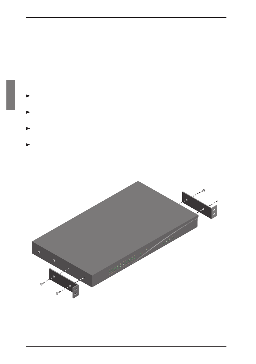
3.1.3.1 Installing the rack mount brackets
Line up the holes in the “long side” of the kit’s side brackets with the screw
holes in the switch.
With a Phillips screwdriver, fasten the mounting brackets to the switch using
two 8/32” x 1/2” pan head screws on each side.
Attach the four cage nuts or clip nuts to the rack mounting ange of the rack
cabinet so that the nut is positioned on the inside of the rack.
Mount the switch assembly to the rack cabinet by matching the holes in the
“short side” of each bracket to an appropriate set of matching holes on your
rack cabinet. Next, insert the combination hex head screws through the slots
in the bracket and the holes in the mounting rail, then into the cage nuts or clip
nuts.
Figure 1: KVM s2-1611 Horizontal Installation
6 590-332-501E
Page 15

KVM series2-1611
KVM s2-1611 hardware
3.2 KVM series2-1611 hardware
The following table lists the port and connection information for your appliance.
Server Ports
Number 16
Types PS/2, Sun and USB KVM s2-Adapters
Connectors RJ45
Sync Types Separate horizontal and vertical
Plug and Play DDC2B
Video Resolution Analog Port Maximum: 1600 x 1280 @ 75 Hz
Digital Port Maximum 1280 x 1024 @ 75 Hz
Conguration Port
Number 1
Type Serial RS232 with terminal set to 9600 baud, 8
bits, 1 stop bit, no parity and no ow control
Connector DB9 Male
Network Connection
Number 1
Type Ethernet: IEEE 802.3, 10BaseT,
Fast Ethernet: IEEE 802.3U, 100BaseT
Connector RJ45
Analog Port
Number 1
Type PS/2 and VGA
Connectors PS/2 MiniDIN and 15-pin D
Table 1: KVM s2-1611 Ports and Connections
590-332-501E 7
Page 16

Power, Dimensions and Standards
KVM series2-1611
3.2.1 Power ratings
Heat Dissipation 92 BTU/Hr
Airow 8 cfm
Power Consumption 25 W
AC-input power 40 W maximum
AC-input voltage rating 100 to 240 VAC Autosensing
AC-input voltage rating 100 to 240 VAC Autosensing
AC-input current rating 1A
AC-input cable 18 AWG three-wire cable, with a three-lead
IEC-320 receptacle on the power supply end
and a country or region dependent plug on the
power resource end
AC-frequency 50/60 Hz
Table 2: KVM s2-1611 Power Ratings
3.2.2 Dimensions and environmental conditions
Dimensions
(H x W x D) 4.45 x 43.18 x 27.94 cm 1U form factor
(1.75 x 17.00 x 11.00 in)
Weight 3.6 kg (8 lb) without cables
Environmental
Temperature 10º to 50º Celsius( 50º to 122º Fahrenheit)
operating
-20º to 60º Celsius (-4º to 140º Fahrenheit)
nonoperating
Humidity 20 to 80% noncondensing operating
5 to 95% noncondensing nonoperating
Table 3: KVM s2-1611 Dimensions and Environmental Information
3.2.3 Standards
Agency Approvals
Table 4: KVM s2-1611 Standard Information
8 590-332-501E
EN55022 Class A, EN55024, EN61000-3-3,
FCC15 Class A, VCCI Class A,
IEC950, EN60950, UL 1950/60950 third edition,
CSA C22.2 No. 950
Page 17
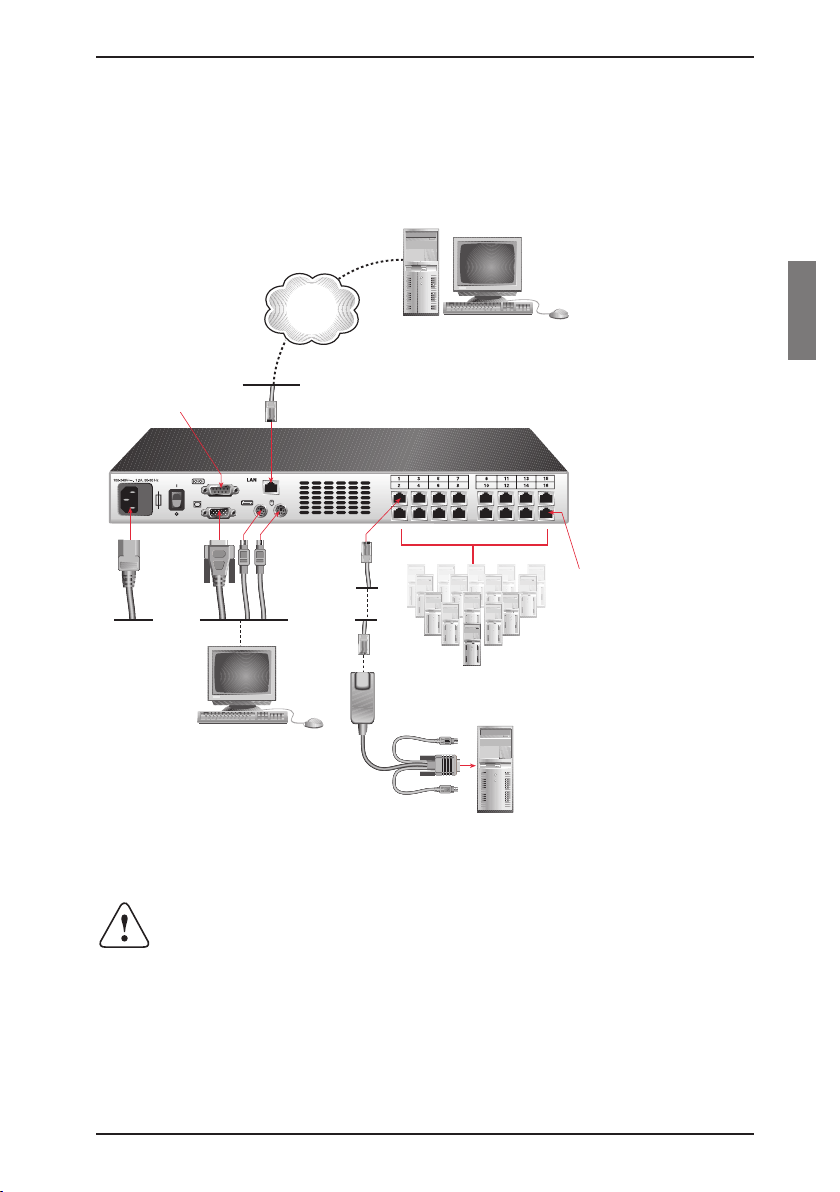
KVM series2-1611
KVM s2-1611 Appliance
Digital User
Server 1
Local Analog
User
Servers 2-16
Configuration Port
for updating firmware
KVM s2-Adapter
PS/2, USB and
Sun cables are
available
RI
Port
Power Cord
Network
Installing the KVM s2-1611
3.3 Installing the KVM series2-1611
Figure 2 illustrates one possible conguration for your KVM s2-1611 appliance.
Follow the detailed set of procedures following Figure 2 to successfully install your
appliance.
Figure 2: Basic KVM s2-1611 Conguration
Reducing the risk of electric shock or damage to your equipment
• Do not disable the power cord grounding plug. The grounding plug
is an important safety feature.
• Plug the power cord into a grounded (earthed) outlet that is easily
accessible at all times.
• Disconnect the power from the unit by unplugging the power cord
590-332-501E 9
from either the electrical outlet or the unit.
Page 18
Installing/Conguring the KVM s2-1611
KVM series2-1611
3.3.1 Installing the KVM series2-1611 hardware
Connect a terminal or PC running terminal emulation software (such as
HyperTerminal) to the conguration port on the back panel of the appliance
using a RS232 DB9 null modem cable. The terminal should be set to 9600
baud, 8 bits, 1 stop bit, no parity and no ow control.
Plug the supplied power cord into the back of the appliance and then into an
appropriate power source.
When you turn on the power, the Power indicator on the front of the unit will
blink for 30 seconds while performing a self-test. Approximately 10 seconds
after it stops blinking, press the Enter key to access the main menu.
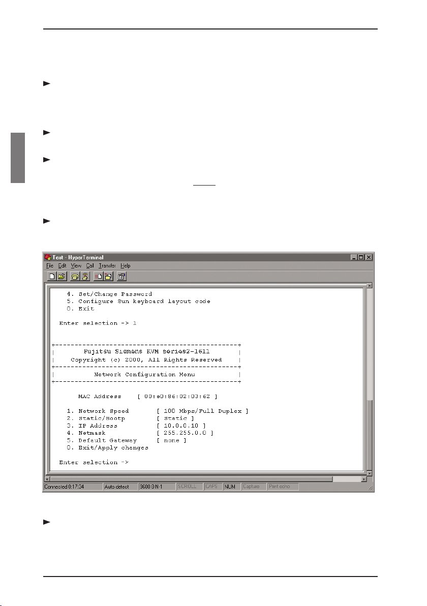
3.3.2 Conguring the KVM series2-1611 hardware
You will see the Terminal Applications menu with six options. Select option 1,
Network Conguration.
Figure 3: Network Conguration Menu
Select option 1 to set your network speed. When possible, you should set
your connection manually without relying on the auto negotiate feature. Once
10 590-332-501E
Page 19

KVM series2-1611
you enter your selection, you will be returned to the Network Conguration
menu.
Select option 2 and specify if you are using a static or BootP IP address. Use
a static IP address for ease of conguration. If you are using a BootP address,
please congure your BootP server to provide an IP address to the appliance,
skip step 4 and continue to the next procedure.
Select options 3-5 from the Terminal Applications menu, in turn, to nish
conguring your appliance for IP address, Netmask and Default Gateway.
Once this is completed, type a Ø (zero) to return to the main menu.
Adjusting the mouse acceleration
3.3.3 Adjusting the mouse acceleration
Before a server can be connected to the KVM s2-1611, an adjustment to mouse
acceleration must be made. Use the default Microsoft® Windows® PS/2 mouse
driver for all attached Microsoft Windows systems attached to the appliance.
3.3.3.1 Adjusting the mouse using Microsoft Windows NT®
(using default drivers)
From the desktop, select Start - Settings - Control Panel - Mouse.
Click on the Motion tab.
Set the pointer speed to Slow. You will need to set this for any Windows NT
user account that will be accessing the Windows NT system through
the appliance.
3.3.3.2 Adjusting the mouse using Microsoft Windows 2000/Windows XP
From the desktop, select Start - Settings - Control Panel - Mouse.
Click on the Motion tab.
Set the Acceleration setting to None and the speed setting to the default of
50%.
3.3.3.3 Adjusting the mouse using Solaris
Open the Workspace menu on your desktop.
Select Applications - Application Manager - Desktop_Controls.
Open the Mouse Style Manager and set the Acceleration to 1.0.
3.3.4 Connecting a KVM s2-Adapter to each server
Locate the KVM s2-Adapters for your KVM s2-1611 unit.
Attach the appropriately color-coded cable ends to the keyboard, monitor and
mouse ports on the rst server you will be connecting to the unit.
590-332-501E 11
Page 20

Connecting an Adapter to each server
1 3 5 7 9 11 13 15
2 4 6 8 10 12 14 16
KVM series2-1611
Attach one end of the CAT 5 cabling that will run between your KVM s2-Adapt-
er and unit to the RJ45 connector on the KVM s2-Adapter.
Connect the other end of the CAT 5 cable to the desired Rack Interface (RI)
port on the back of your KVM s2-1611 unit.
Repeat steps 2-4 for all servers you wish to attach.
When connecting a Sun KVM s2-Adapter, you must use a multi-sync monitor
to accommodate Sun computers that support both VGA and sync-on-green
or composite sync.
3.3.5 Adding a KVM switch
You can add your cascade switches to the KVM s2-1611 system for better inte-
gration into your existing conguration. In a cascaded system, each RI port will
accommodate up to 24 servers.
KVM s2-1611
Appliance
Tiered KVM s2 Appliance
KVM s2-Adapter
PS/2, USB and Sun cables
are available
Cascade to a KVM s2-1611, 1602
or 0801 via a CAT 5 cable connected from an RI port to the ACI
port on the KVM s2-1602
Cascaded
Local Analog
User
Server 1
KVM Switch
KVM s2-Adapter
Server 1
KVM s2-1602 Appliance
Figure 4: KVM s2-1611 Conguration with a Cascaded KVM Switch
12 590-332-501E
Page 21

KVM series2-1611
Mount the KVM switch into your rack cabinet. Locate a length of CAT 5
cabling to connect your appliance to the KVM s2-Adapter for your switch.
Attach one end of the CAT 5 cabling to the RJ45 connector on the KVM s2-
Adapter.
Connect the other end of the CAT 5 cable to a port on the back of your KVM
s2-1611.
Attach the keyboard, monitor and mouse connectors of the KVM s2-Adapter
to a user port on your cascade switch.
Connect the servers to your Fujitsu Siemens cascade switch according to the
instructions included with the device.
Power cycle the switch to enable the cascade code.
Repeat steps 2-5 for all cascade switches you want to attach to your system.
You can also cascade a KVM s2-1611 off of a KVM s2-1602/0801. To do
this, attach one end of a CAT 5 cable to the ACI port on the main KVM
s2-1602/0801. Attach the other end of the CAT 5 cable to an RI port on the
cascaded KVM s2-1611. Note that only one level of tiering is supported in
this type of conguration and the local port OSCAR is disabled when the
main KVM s2-1602/0801 is cascaded below the KVM s2-1611. See the
KVM series2-1602/0801 User Guide for more information on this process.
Connecting/turning on your KVM s2-1611
3.3.6 Connecting the network and turning on your
KVM s2-1611
Connect your network cable from the LAN port on the rear of the KVM s2-
1611 appliance to your network.
The components in the KVM s2-1611 system may be turned on in any order.
However, since the KVM s2-Adapters are powered by the servers, turn on
the servers rst and then turn on all attached systems for the most efcient
startup.
3.4 Setting Up the KVM s2-1611/Client System
See the KVM series2-Client Installer/User Guide that ships with your appliance.
The KVM s2-1611 system has an analog port that allows you to attach a monitor
and a PS/2 keyboard and mouse to the back of the unit. First, set up your servers
at the analog port via OSCAR before proceeding to the Client software to nish
conguring your system. Proceed to the “Operations” chapter in this installer/user
guide for detailed instructions on OSCAR setup and conguration. Once your
servers are named, you will want to use a digital station to congure the Client
590-332-501E 13
Page 22

Setting up the System
software. See the KVM series2-1611 Quick Installation Guide for an overview of
the hardware and software installation procedure.
KVM series2-1611
14 590-332-501E
Page 23

4 Operations
4.1 Controlling Your System at the Analog Port
The KVM s2-1611 includes an analog port on the back of the unit that allows you
to connect a monitor and a PS/2 keyboard and mouse for direct analog access.
The appliance uses OSCAR®, the On-Screen Conguration and Activity Reporting interface, which utilizes intuitive menus to congure your system and select
computers.
4.2 Viewing and Selecting Ports and Servers
Use the OSCAR Main dialog box to view, congure and control servers in the KVM
s2-1611 system. View your servers by name, port or by the unique Electronic ID
number (EID) embedded in each KVM s2-Adapter. You will see an OSCAR-gener-
ated port list by default when you rst launch OSCAR.
The Port column indicates the RI port to which a server is connected. If you connect a legacy KVM switch to the appliance, the port numbering displays the RI port
rst, then the switch port to which the server is connected. For example, in Figure
5, servers 06-03 and 01-02 are connected to switches.
4.2.1 Accessing the Main dialog box
Press Print Screen to launch OSCAR. The Main dialog box appears.
Figure 5: Example of Congured Main Dialog Box
590-332-501E 15
Page 24

Selecting servers
You can also press the Control key twice within one second to launch
OSCAR. You can use this key sequence in any place you see Print Screen
throughout this installer/user guide.
Operations
4.2.2 Viewing the status of your appliance
The status of the servers in your system is indicated in the right columns of the
Main dialog box. The following table describes the status symbols.
OSCAR Symbol Description
KVM s2-Adapter is online.
KVM s2-Adapter is ofine or is not operating properly.
KVM s2-Adapter is being accessed by the indicated user channel.
KVM s2-Adapter is blocked by the indicated user channel. For
instance, in Figure 5, user B is viewing Forester, but is blocking access
to Acton, Barrett and Edie which are connected to the same KVM s2Adapter chain.
Table 5: OSCAR Status Symbols
4.2.3 Selecting servers
Use the Main dialog box to select servers. When you select a server, the
appliance recongures the keyboard and mouse to the proper settings for that
server.
Double-click the server name, EID or port number.
-orIf the display order of your server list is by port (Port button is depressed),
type the port number and press Enter .
-orIf the display order of your server list is by name or EID number (Name or EID
button is depressed), type the rst few characters of the name of the server or
the EID number to establish it as unique and press Enter .
4.2.3.1 Selecting the previous server
Press Print Screen and then Backspace. This key combination toggles you
between the previous and current connections.
4.2.3.2 Disengaging the user from a server
Press Print Screen and then Alt+Ø . This leaves the user in a free state, with
no server selected. The status ag on your desktop displays Free.
16 590-332-501E
Page 25

Operations
Navigating OSCAR
4.2.4 Soft switching
Soft switching is the ability to switch servers using a hot key sequence. You can
soft switch to a server by pressing Print Screen and then typing the rst few characters of its name or number. If you have set a Screen Delay Time and you press
the key sequences before that time has elapsed, OSCAR will not display.
4.2.4.1 Conguring servers for soft switching
Press Print Screen to launch OSCAR. The Main dialog box appears.
Click Setup - Menu. The Menu dialog box appears.
For Screen Delay Time, type the number of seconds of delay desired before
the Main dialog box is displayed after Print Screen is pressed.
Click OK.
4.2.4.2 Soft switching to a server
To select a server, press Print Screen. If the display order of your server list is
by port (Port button is depressed), type the port number and
press Enter .
-orIf the display order of your server list is by name or EID number (Name or EID
button is depressed), type the rst few characters of the name of the server or
the EID number to establish it as unique and press Enter .
To switch back to the previous server, press Print Screen then Backspace.
4.3 Navigating OSCAR
This table describes how to navigate OSCAR using the keyboard and mouse.
This Keystroke Does This
Print Screen Opens OSCAR. Press Print Screen twice
to send the Print Screen keystroke to the
currently selected device.
F1 Opens the Help screen for the current
dialog box.
Escape Closes the current dialog box without saving
changes and returns to the previous one.
In the Main dialog box, it closes OSCAR
and returns to the ag. In a message box,
it closes the pop-up box and returns to the
current dialog box.
590-332-501E 17
Page 26

Navigating OSCAR
Operations
This Keystroke Does This
Alt Opens dialog boxes, selects or checks
options and executes actions when used with
underlined or other designated letters.
Alt+X Closes the current dialog box and returns to
the previous one.
Alt+O Selects the OK button, then returns to the
previous dialog box.
Single-click, Enter In a text box, it selects the text for editing
and enables the Left and Right Arrow keys
to move the cursor. Press Enter again to quit
the edit mode.
Enter Completes a switch in the Main dialog box
and exits OSCAR.
Print Screen, Backspace Toggles back to previous selection.
Print Screen, Alt+ Ø Immediately disengages user from a server;
no server is selected. Status ag displays
Free. (This only applies to the Ø on the
keyboard and not the keypad.)
Print Screen, Pause Immediately turns on screen saver mode and
prevents access to that particular console, if
it is password protected.
Up/Down Arrows Moves the cursor from line to line in lists.
Right/Left Arrows Moves the cursor between columns. When
editing a text box, these keys move the
cursor within the column.
Page Up/Page Down Pages up and down through Name and Port
lists and Help pages.
Home/End Moves the cursor to the top or bottom of
a list.
Backspace Erases characters in a text box.
Delete Deletes current selection in the scan list or
characters in a text box.
Shift-Del Deletes from the current selection to the end
of the list when editing a scan list.
Numbers Type from the keyboard or keypad.
Caps Lock Disabled. Use the Shift key to change case.
Table 6: OSCAR Navigation Basics
18 590-332-501E
Page 27

Operations
Conguring OSCAR
4.4 Conguring OSCAR
You can congure your KVM s2-1611 system from the Setup menu within OSCAR.
Select the Names button when initially setting up your appliance to identify servers
by unique names. Select the other setup features to manage routine tasks for your
servers from the OSCAR menu.
Setup Feature Purpose
Menu Change the server listing between
numerically by port or EID number and
alphabetically by name. Change the Screen
Delay Time before OSCAR displays after
pressing Print Screen .
Flag Change display, timing, color or location of
the status ag.
Broadcast Set up to simultaneously control
multiple servers through keyboard and
mouse actions.
Scan Set up a custom scan pattern for up to
16 servers.
Security Set passwords to restrict server access.
Enable the screen saver.
Devices Identify the appropriate number of ports on
an attached cascade switch.
Names Identify servers by unique names.
Table 7: OSCAR Navigation Basics
4.4.1 Accessing the Setup menu
Press Print Screen to launch OSCAR. The Main dialog box appears.
Click Setup. The Setup dialog box appears.
590-332-501E 19
Page 28

Accessing the Setup menu
Figure 6: Setup Dialog Box
Operations
4.4.2 Assigning server names
Use the Names dialog box to identify individual servers by name rather than by
port number. The Names list is always sorted by port order. Names are stored in
the KVM s2-Adapter, so even if you move the cable/server to another RI port, the
name and conguration will be recognized by the appliance.
If a server is turned off, its respective KVM s2-Adapter will not appear in
the Names list.
4.4.2.1 Accessing the Names dialog box
Press Print Screen . The Main dialog box will appear.
Click Setup - Names. The Names dialog box appears.
Figure 7: Names Dialog Box
20 590-332-501E
Page 29

Operations
If the server list changes, the mouse cursor will turn into an hourglass as
the list is automatically updated. No mouse or keyboard input will be accepted until the list update is complete.
4.4.2.2 Assigning names to servers
In the Names dialog box, select a server name or port number and click
Modify. The Name Modify dialog box appears.
Assigning names to servers
Figure 8: Name Modify Dialog Box
Type a name in the New Name box. Names of servers may be up to 15
characters long. Legal characters include: A-Z, a-z, Ø-9, space and hyphen.
Click OK to transfer the new name to the Names dialog box. Your selection is
not saved until you click OK in the Names dialog box.
Repeat steps 1-3 for each server in the system.
Click OK in the Names dialog box to save your changes.
-orClick X or press Escape to exit the dialog box without saving changes.
If a KVM s2-Adapter has not been assigned a name, the EID is used as
the default name.
4.4.3 Assigning device types
While the appliance automatically discovers cascade switches attached to your
unit, you will need to specify the number of ports on the cascade switch through
the Devices dialog box. The appliance recognizes KVM switches. You will see an
Sw-8 or Sw-24 appear in the Type category. When you select that switch from the
list, the Modify button appears, allowing you to assign the appropriate number of
ports to it.
590-332-501E 21
Page 30

Assigning device types
4.4.3.1 Accessing the Devices dialog box
Press Print Screen. The Main dialog box will appear.
Click Setup - Devices. The Devices dialog box appears.
The Modify button will only be available if a congurable switch
is selected.
Figure 9: Devices Dialog Box
Operations
When the KVM s2-1611 appliance discovers a cascade switch, you will notice the
port numbering change to accommodate each server under that switch. For example, if the switch is connected to RI port 6, the switch port would be listed as 06
and each server under it would be numbered sequentially 06-01, 06-02 and so on.
4.4.3.2 Assigning a device type
In the Devices dialog box, select the desired port number.
Click Modify. The Device Modify dialog box appears.
22 590-332-501E
Page 31

Operations
Figure 10: Device Modify Dialog Box
Choose the number of ports supported by your switch and click OK.
This appliance does not support 24 port switches at this time.
Repeat steps 1–3 for each port that needs a device type assigned.
Click OK in the Devices dialog box to save settings.
Changes made in the Device Modify dialog box are not saved until you
click OK in the Devices dialog box.
Changing the display behavior
4.4.4 Changing the display behavior
Use the Menu dialog box to change the display order of servers and set a Screen
Delay Time for OSCAR. The display order setting alters how servers will display in
several screens including the Main, Devices and Broadcast dialog boxes.
4.4.4.1 Accessing the Menu dialog box
Press Print Screen to launch OSCAR. The Main dialog box appears.
Click Setup - Menu in the Main dialog box. The Menu dialog box appears.
590-332-501E 23
Page 32

Setting a Screen Delay Time
Figure 11: Menu Dialog Box
4.4.4.2 Choosing the default display order of servers
Select Name to display servers alphabetically by name.
-orSelect EID to display servers numerically by EID number.
-orSelect Port to display servers numerically by port number.
Click OK.
4.4.4.3 Setting a Screen Delay Time for OSCAR
Type in the number of seconds (Ø-9) to delay OSCAR display after you press
Print Screen. Entering Ø will instantly launch OSCAR with no delay.
Click OK.
Setting a Screen Delay Time allows you to complete a soft switch without OSCAR
displaying. To perform a soft switch, see Soft switching in this chapter.
Operations
4.4.5 Controlling the status ag
The status ag displays on your desktop and shows the name or EID number of
the selected server or the status of the selected port. Use the Flag dialog box to
congure the ag to display by server name or EID number, or to change the ag
color, opacity, display time and location on the desktop.
24 590-332-501E
Page 33

Operations
Controlling the status ag
OSCAR Flag Description
Flag type by name
Flag type by EID number
Flag indicating that the user has
been disconnected from
all systems
Flag indicating that Broadcast mode
is enabled
Table 8: OSCAR Status Flags
4.4.5.1 Accessing the Flag dialog box
Press Print Screen . The Main dialog box will appear.
Click Setup - Flag. The Flag dialog box appears.
Figure 12: Flag Dialog Box
4.4.5.2 Determining how the status ag is displayed
Select Name or EID to determine what information will be displayed.
Select Displayed to show the ag all the time or select Timed to display the
ag for only ve seconds after switching.
Select a ag color in Display Color.
In Display mode, select Opaque for a solid color ag or select Transparent to
see the desktop through the ag.
590-332-501E 25
Page 34

Seting console security
To position the status ag on the desktop:
a. Click Set Position to gain access to the Position Flag screen.
b. Left-click on the title bar and drag to the desired location.
c. Right-click to return to the Flag dialog box.
Figure 13: Position Flag
Changes made to the ag position are not saved until you click OK in the
Flag dialog box.
Click OK to save settings.
-orClick X to exit without saving changes.
Operations
4.4.6 Setting console security
OSCAR enables you to set security on your analog port console. You can establish a screen saver mode that engages after your console remains unused for a
specied Inactivity Time. Once engaged, your console will remain locked until you
press any key or move the mouse. You will then need to type in your password to
continue.
Use the Security dialog box to lock your console with password protection, set or
change your password and enable the screen saver.
If a password has been previously set, you will have to enter the password
before you can access the Security dialog box.
4.4.6.1 Accessing the Security dialog box
Press Print Screen . The Main dialog box will appear.
Click Setup - Security. The Security dialog box appears.
26 590-332-501E
Page 35

Operations
Figure 14: Security Dialog Box
4.4.6.2 Setting or changing the password
Single-click and press Enter or double-click in the New text box.
Type the new password in the New text box and press Enter .
Passwords must contain both alpha and numeric characters, are case sensitive and may be up to 12 characters long. Legal characters are: A-Z, a-z, Ø-9,
space and hyphen.
In the Repeat box, type the password again and press Enter .
Click OK to change only your password, and then close the dialog box.
If you should lose or forget your password, you must return your switch.
See theTechnical Support section for contact information.
Setting or changing the password
4.4.6.3 Password protecting your console
Set your password as described in the previous procedure.
Select Enable Screen Saver.
Type the number of minutes for Inactivity Time (from 1 to 99) to delay activa-
tion of password protection and the screen saver feature.
For Mode, select Energy if your monitor is Energy Star®compliant; otherwise
select Screen.
Monitor Damage
Monitor damage can result from the use of Energy mode with monitors
not compliant with Energy Star®.
(Optional) Click Test to activate the screen saver test which lasts 10 seconds
590-332-501E 27
Page 36

Enabling/exiting Screen saver mode
then returns you to the Security dialog box.
Click OK.
4.4.6.4 Logging in to your console
Press any key or move the mouse.
The Password dialog box appears. Type your password, then click OK.
The Main dialog box appears if the password was entered properly.
4.4.6.5 Removing password protection from your console:
From the Main dialog box, click Setup - Security; the Password dialog box ap-
pears. Type your password, then click OK.
In the Security dialog box, single-click and press Enter or double-click in the
New box. Leave the box blank. Press Enter .
Single-click and press Enter or double-click in the Repeat box. Leave the box
blank. Press Enter .
Click OK to eliminate your password.
4.4.6.6 Enabling the screen saver mode with no password protection
If your console does not require a password to gain access to the Security
dialog box, proceed to step 2.
-orIf your console is password protected, see the previous procedure, then go to
step 2.
Operations
Select Enable Screen Saver.
Type the number of minutes for Inactivity Time (from 1–99) to delay activation
of the screen saver.
Choose Energy if your monitor is Energy Star® compliant; otherwise select
Screen.
Monitor Damage
Monitor damage can result from the use of Energy mode with monitors
not compliant with Energy Star®.
(Optional) Click Test to activate the screen saver test which lasts 10 seconds
then returns you to the Security dialog box.
Click OK.
28 590-332-501E
Page 37

Operations
Activation of the screen saver mode disconnects the user from a server; no
server is selected. The status ag displays Free.
4.4.6.7 Exiting the screen saver mode
Press any key or move your mouse. The Main dialog box appears and any previous server connection will be restored.
4.4.6.8 Turning off the screen saver
In the Security dialog box, clear Enable Screen Saver.
Click OK.
4.4.6.9 Immediately turning on the screen saver
Press Print Screen, then press Pause .
Viewing/Disconnecting Connections
4.5 Viewing/Disconnecting User Connections
You can view and disconnect users through the User Status dialog box. The user
name (U) will always be displayed; however, you can display either the server
name or EID number to which a user is connected. If there is no user currently
connected to a channel, the user eld will be blank and the server eld will display
Free.
4.5.1 Viewing current user connections
Press Print Screen . The Main dialog box will appear.
Click Commands - User Status. The User Status dialog box appears.
4.5.1.1 Disconnecting a user
Press Print Screen . The Main dialog box will appear.
Click Commands - User Status. The User Status dialog box appears.
Click the letter of a user to disconnect. The Disconnect dialog box will appear.
590-332-501E 29
Page 38

Resetting Your Keyboard/Mouse
Figure 15: User Status Dialog Box Figure 16: Disconnect Dialog Box
Click OK to disconnect the user and return to the User Status dialog box.
-orClick X or press Escape to exit the dialog box without disconnecting a user.
If the User Status list has changed since it was last displayed, the mouse
cursor will turn into an hourglass as the list is automatically updated. No
mouse or keyboard input will be accepted until the list update is complete.
Operations
4.6 Resetting Your Keyboard and Mouse
If your keyboard or mouse locks up, you may be able to re-establish operation of
these peripherals by issuing a reset command. The reset command sends a key
sequence to the server which causes the mouse and keyboard settings to be sent
to the appliance. With communication re-established between the server and the
appliance, functionality is restored to the user.
4.6.1 Resetting the mouse and keyboard values
Press Print Screen . The Main dialog box will appear.
Click Commands - Reset PS/2. A message box displays indicating that the
mouse and keyboard have been reset.
Click X to close the message box.
4.7 Displaying Version Information
OSCAR enables you to display the KVM s2-1611 and KVM s2-Adapter rmware
versions. For optimum performance, keep your rmware current. For more infor-
mation, see Chapter 5.
30 590-332-501E
Page 39

Operations
Press Print Screen . The Main dialog box will appear.
Click Commands - Display Versions. The Version dialog box appears. The top
half of the box lists the subsystem versions in the appliance.
Figure 17: Version Dialog Box
Click Digital to view the Digitizer unit rmware versions. The Digital Version
dialog box appears. The top section identies the Digitizer subsystem versions. The center section identies the current network settings. Click X or
press Escape to return to the Version dialog box.
Displaying Version Information
Figure 18: Digital Version Dialog Box
Click KVMS2 (see Figure 17) to view individual KVM s2-Adapter version infor-
mation. The KVM s2-Adapter Selection dialog box appears.
590-332-501E 31
Page 40

Scanning Your System
Figure 19: KVM s2-Adapter Selection Dialog Box
Select a KVM s2-Adapter to view and click the Version button. The KVM s2-
Adapter Version dialog box appears. For more information on loading rmware, see Chapter 5.
Operations
Figure 20: KVM s2-Adapter Version Dialog Box
Click X to close the Version dialog box.
4.8 Scanning Your System
In scan mode, the appliance automatically scans from port to port (server to
server). You can scan up to 16 servers, specifying which servers to scan and the
number of seconds that each server will display. The scanning order is determined
by placement of the server in the list. The list is always shown in scanning order.
You can, however, choose to display the server’s name or EID number by pressing the appropriate button.
32 590-332-501E
Page 41

Operations
Scanning is only available to the analog user.
Adding servers to the scan list
4.8.1 Adding servers to the scan list
Press Print Screen . The Main dialog box will appear.
Click Setup - Scan. The Scan dialog box appears.
Figure 21: Scan Dialog Box
Determine the order within the list to add the server. If there are no servers in
the scan list, your cursor will appear in a blank line at the top of the list.
-or-
To add a server to the end of the list, place your cursor in the last server entry
and press the Down Arrow key.
-orTo add a server in the midst of an existing list, place your cursor in the line
below where you want to insert a new server and press Insert .
Type the rst few characters of a server name or port number to scan. The
rst matching server will appear in the line.
-orTo move through the list, press the following keyboard commands in the
Name, Port or Sec column to move through the list of servers available
to scan.
a. Press Alt+Down Arrow to move the cursor down through the list
of servers.
b. Press Alt+Up Arrow to move the cursor up through the list of servers.
c. Press Alt+Home to move the cursor to the rst server in the list.
590-332-501E 33
Page 42
Starting the scan mode
d. Press Alt+End to move the cursor to the last server in the list.
In the Sec column, type the number of seconds (from 3 to 255) of desired time
before the scan moves to the next server in the sequence.
Move the cursor to the next line or press the Down Arrow and repeat steps 2-5
for each of the remaining servers to be included in the
scan pattern.
Click OK.
Operations
4.8.2 Removing a server from the scan list
In the Scan dialog box, click the server to be removed.
Press Delete .
-orPress Shift+Delete to remove the selected server and all entries below it.
Click OK.
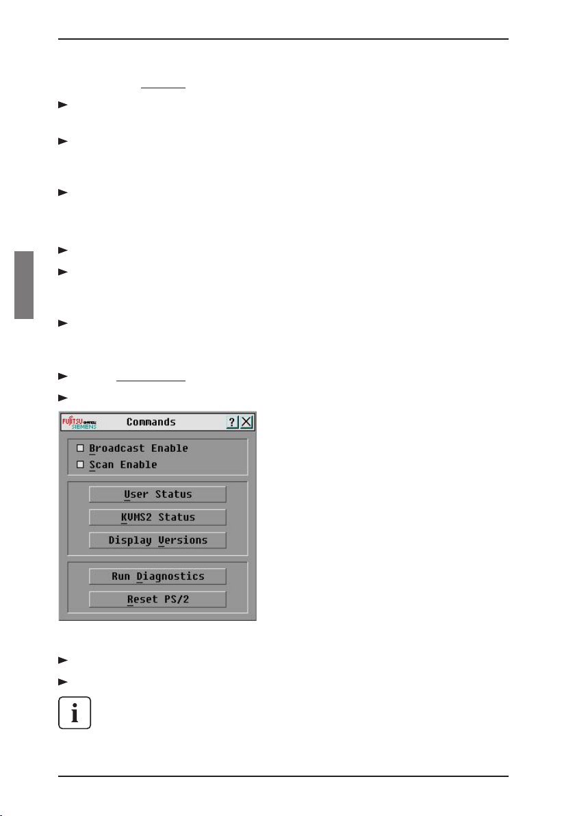
4.8.3 Starting the scan mode
Press Print Screen . The Main dialog box will appear.
Click Commands. The Commands dialog box appears.
Figure 22: Commands Dialog Box
Select Scan Enable in the Commands dialog box.
Click X to close the Commands dialog box.
Scanning will commence when the Main dialog box or ag is displayed.
Scanning is inhibited in any other OSCAR dialog box.
34 590-332-501E
Page 43
Operations
Accessing the Broadcast dialog box
4.8.4 Cancelling scan mode
Select a server if OSCAR is open.
-orMove the mouse or press any key on the keyboard if OSCAR is not open.
Scanning will stop at the currently selected server.
-orPress Print Screen . The Main dialog box will appear.
Click Commands. The Commands dialog box appears.
Clear Scan Enable.
4.9 Broadcasting to Servers
The analog user can simultaneously control more than one server in a system, to
ensure that all selected servers receive identical input. You can choose to broadcast keystrokes and/or mouse movements independently.
You can broadcast to up to 16 servers at a time, one server per RI port.
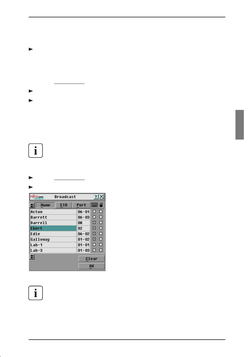
4.9.1 Accessing the Broadcast dialog box
Press Print Screen . The Main dialog box will appear.
Click Setup - Broadcast. The Broadcast dialog box appears.
Figure 23: Broadcast Dialog Box
When broadcasting keystrokes, the keyboard state must be identical for all
servers receiving a broadcast to interpret keystrokes identically. Specically, the Caps Lock and Num Lock modes must be the same on all keyboards. While the appliance attempts to send keystrokes to the selected
servers simultaneously, some servers may inhibit and thereby delay the
transmission.
590-332-501E 35
Page 44

Terminal Operations
When broadcasting mouse movements, all systems must have identical
mouse drivers, desktops (such as identically placed icons) and video resolutions for the mouse to work accurately. In addition, the mouse must be in exactly the same place on all screens. Because these conditions are extremely
difcult to achieve, broadcasting mouse movements to multiple systems may
have unpredictable results.
4.9.1.1 Broadcasting to selected servers:
From the Broadcast dialog box, select the mouse and/or keyboard checkbox-
es for the servers that are to receive the broadcast commands.
-orPress the Up or Down Arrow keys to move the cursor to the target server.
Then press Alt+K to select the keyboard checkbox and/or Alt+M to select the
mouse checkbox. Repeat for additional servers.
Click OK to save the settings and return to the Setup dialog box. Click X or
press Escape to return to the Main dialog box.
Click Commands. The Commands dialog box appears.
Click the Broadcast Enable checkbox to activate broadcasting.
From the user station, type the information and/or perform the mouse move-
ments you want to broadcast.
4.9.1.2 Turning broadcasting off
From the Commands dialog box, clear the Broadcast Enable checkbox.
Operations
4.10 Terminal Operations
Each individual KVM s2-1611 may be congured at the unit level through the
conguration port on the back of the unit. All Terminal commands are accessed
through a terminal or PC running terminal emulation software.
4.10.1 Conguring the Terminal menu
The KVM s2-1611 Terminal Applications menu features ve selections: Network
Conguration, Firmware Management, Enable Debug Messages, Set/Change
Password and Exit.
36 590-332-501E
Page 45

Operations
Figure 24: Network Conguration Menu
4.10.1.1 Accessing the Terminal menu
Connect a terminal or PC running terminal emulation software (such as
HyperTerminal) to the conguration port on the back panel of the KVM s2-
1611 using a RS232 DB9 null modem cable. The terminal should be set to
9600 baud, 8 bits, 1 stop bit, no parity and no ow control. The terminal may
be connected at any time, even when the unit is powered.
Press any key to access the main menu.
Network Conguration
4.10.2 Network Conguration
The KVM s2-1611 is congured for network access through the Network
Conguration option. When it is selected, you will have access to the addressing
that allows the KVM s2-1611 to be positioned in your network. For more
information, see Installing the KVM s2-1611 in Chapter 3.
4.10.2.1 Firmware Management
This menu option contains the FLASH Download command. The FLASH Download selection allows you to keep your KVM s2-1611 rmware current with upgrades available from Fujitsu Siemens. For more information, see Chapter 5.
4.10.2.2 Enable Debug Messages
This menu option allows you to congure the KVM s2-1611 to display messages
regarding the status of the KVM s2-1611. Once you select the level of detail to receive,
the KVM s2-1611 will begin to display information on your terminal screen. When you
are nished viewing, press any key to exit this mode.
4.10.2.3 Set/Change Password
The KVM s2-1611 can be set to a secure mode where the Terminal menu cannot
590-332-501E 37
Page 46

Exit
be accessed without rst entering a password.
4.10.2.3.1 Activating security
Select the Set/Change Password menu option. You will be prompted with the
option to continue. Enter a Y .
Type a password for this KVM s2-1611 and press Enter. This password must
be a minimum of 5 characters and can be up to a maximum of 12 characters
(10 are visible). The password must consist of a combination of alpha and
numeric characters.
You will be prompted to re-type the password. Once you complete this step,
security will be active and you will not be able to access KVM s2-1611 terminal operations without the password.
4.10.2.3.2 Changing the password
Select the Set/Change Password menu option.
You will be prompted to type the old password and a new one.
Re-enter the new password to verify.
This password places your KVM s2-1611 terminal in a secure mode. This password should be guarded like any network password and care should be taken to
avoid forgetting or misplacing it. There are no means for recovering a lost password.
4.10.2.4 Exit
This menu selection will return you to the ready prompt.
Operations
38 590-332-501E
Page 47

5 Appendices
5.1 FLASH Upgrades
The KVM s2-1611 FLASH upgrade feature allows you to upgrade your unit with
the latest rmware available. To perform this update you will need a TFTP server.
If you don’t already have a TFTP server, there are several you can download from
the internet.
If you upgrade the appliance rmware, please verify the individual rmware of
the KVM s2-Adapters. The upgrade of the adapters requires a separate upgrade
procedure which is found in Chapter 4.
Next, you will need to copy the FLASH upgrade le (. le extension) from the CD.
Save the FLASH upgrade le to the appropriate directory on the TFTP server. Once
this is complete, the following steps will upload the new FLASH le.
When upgrading your switch rmware, ensure that the keyboard country codes with your system correspond with the rmware loaded in your
switch. Contact Fujitsu SiemensTechnical Support for more information. Technical Support contact information is available at the end of this
manual.
5.1.1. Uploading a new FLASH le
Connect a terminal or PC running terminal emulation software (such as
HyperTerminal) to the conguration port on the back panel of the KVM s2-1611
using a straight-through null modem cable. The terminal should be set to 9600
baud, 8 bits, 1 stop bit, no parity and no ow control.
Connect the LAN port on the KVM s2-1611 to an Ethernet hub that is also
connected to the PC being used as the TFTP server.
Launch both the server software and the terminal emulation software.
Verify that the KVM s2-1611 is turned on. After approximately 40 seconds, the
KVM s2-1611 will send out a message, Fujitsu Siemens KVM series2-1611
Ready__Press any key to continue. Press any key to access the main menu.
The KVM s2-1611 main menu appears.
Get the IP address of the TFTP server: If using the SolarWinds TFTP server, it
appears in the lower right-hand corner of the server’s pane. Otherwise, extract
it from the OS tools (may be OS-dependent):
a. Right-click on Network Neighborhood.
b. Select Properties.
c. Select the Protocols tab.
d. Select TCP/IP protocol.
e. Select Properties and note the IP address.
590-332-501E 39
Page 48

Upgrading the rmware Appendices
Assign the IP address in the KVM s2-1611, if needed:
a. In the HyperTerminal window, type 1 to select Network Conguration.
b. Note the KVM s2-1611 IP address. The rst three numbers must be the
same as in the server’s IP address from step 5 above. The last number
must be different.
If the KVM s2-1611 IP address is not correct, change it as follows: type 3
to select IP address, then enter the correct address.
c. Type Ø to exit the Network Conguration menu. If you changed the IP
address, wait per the directions on the screen.
From the main menu, type 2 to select Firmware Management. The current
version of your rmware displays in the Firmware Management screen.
From the Firmware Management menu, type 1 to select FLASH Download.
Type the IP address of the TFTP server and press Enter .
Type the name of the FLASH le and press Enter .
Conrm the TFTP download by typing y or yes and pressing Enter .
The KVM series2-1611 will verify the le you downloaded is valid. Next you
will be prompted to conrm the upgrade. Type y or yes and Enter .
The KVM series2-1611 will begin the FLASH upgrade process. On-screen indi-
cators will display the upgrade process. When the upload is complete, the KVM
series2-1611 will reset and upgrade the internal subsystems.
Power Loss
Do not cycle power to the KVM s2-1611 during this process. A loss of
power might render the appliance inoperable and require the unit be returned to the factory for repair. This upgrade may take up to 10 minutes
to complete.
Once the upgrade is complete, the startup message from step 4 will appear
on the terminal screen.
5.1.2 Upgrading the KVM s2-Adapter rmware
The KVM s2-Adapters can be upgraded individually or simultaneously.
Do not cycle power to the server or disconnect the KVM s2-Adapter during
this process. A loss of power will render the KVM s2-Adapter inoperable and
require the switch to be returned to the factory for repair.
5.1.2.1 Simultaneously upgrading multiple KVM s2-Adapters
Press Print Screen . The Main dialog box will appear.
Click Commands - KVM s2-Adapter Status. The KVM s2-Adapter Status
dialog box appears.
40 590-332-501E
Page 49

Upgrading rmwareAppendices
Figure 25: KVM s2-Adapter Status Dialog Box
Click one or more types of adapters to upgrade. Click Upgrade.
Figure 26: KVM s2-Adapter Upgrade Dialog Box
The KVM s2-Adapter Upgrade dialog box appears. Click OK to initiate the
upgrade and return to the KVM s2-Adapter Status dialog box.
5.1.2.2 Upgrading KVM s2-Adapter rmware individually
Press Print Screen . The Main dialog box will appear.
Click Commands - Display Versions. The Version dialog box appears.
590-332-501E 41
Page 50

Upgrading rmware individually Appendices
Figure 27: Version Dialog Box
Click KVMS2 to view individual cable version information.
Figure 28: KVM s2-Adapter Selection Dialog Box
Select a KVM s2-Adapter to upgrade and click the Version button. The KVM
s2-Adapter Version dialog box appears.
42 590-332-501E
Page 51

Upgrading rmware individuallyAppendices
Figure 29: KVM s2-Adapter Version Dialog Box
Click the Load Firmware button. The Load dialog box appears.
Figure 30: KVM s2-Adapter Load Dialog Box
Click OK to initiate the upgrade and return to the Status dialog box.
During an upgrade, the KVM s2-Adapter status indicator in the Main dialog
box will be yellow. The KVM s2-Adapter is unavailable while an upgrade
is in progress. When an upgrade is initiated, any current connection to the
server via the KVM s2-Adapter will be terminated.
5.2 Sun Advanced Key Emulation
Certain keys on a standard Type 5 (US) Sun keyboard may be emulated by key
press sequences on a PS/2 keyboard. To enable Advanced Sun Key Emulation
mode and use they keys, press and hold Ctrl+Shift+Alt and then press the Scroll
590-332-501E 43
Page 52

AppendicesSun Advanced Key Emulation
Lock key. The Scroll Lock LED blinks. Use the indicated key in the following table
as you would use the advanced keys on a Sun keyboard.
Sun Key (US) PS/2 Key Combination
Compose Application
Compose keypad *
Power F11
Open F7
Help Num Lock
Props F3
Front F5
Stop F1
Again F2
Undo F4
Cut F10
Copy F6
Paste F8
Find F9
Mute keypad /
Vol. + keypad +
Vol. - keypad -
Command (left)
Command (left)
Command (right)
(1) Windows 95 104-key keyboard
(2) The Command key is the Sun Meta (diamond) key
For example: For Stop + A, press and hold Ctrl+Shift+Alt and press Scroll Lock,
then F1 + A .
These key combinations will work with the USB KVM series2-Adapters (if your
Sun system comes with a USB port) as well as the Sun KVM series2- Adapters.
With the exception of Scroll Lock+F12, these key combinations are not recognized
by Microsoft Windows. The Scroll Lock+F12 combination performs a Windows key
press.
(2)
(2)
(2)
F12
Win (GUI) left
Win (GUI) right
(1)
(1)
44 590-332-501E
Page 53

Appendices
Technical Support
5.3 Technical Support
Our Technical Support staff is ready to assist you with any installation or operating issues you encounter with your Fujitsu Siemens product. If an issue should
develop, follow the steps below for the fastest possible service:
Check the pertinent section of this manual to see if the issue can be resolved
by following the procedures outlined.
Check our web site at www.fujitsu-siemens.com/support and click on Services
& Support. Click helpdesk on the left side of the page for a listing of technical
support phone numbers in your area.
590-332-501E 45
Page 54

46 590-332-501E
Page 55

Fujitsu Siemens Computers GmbH
User Documentation
33094 Paderborn
Germany
email: manuals@fujitsu-siemens.com
http://manuals.fujitsu-siemens.com
Submitted by
Comments on KVM series2-1611
Comments
Suggestions
Corrections
Page 56

Page 57

 Loading...