

Page 1

User's Guide - English
Analog KVM Switch
User's Guide
CA92344-1926
November 2017
Page 2

Page 3

Safety and Usage environment
i
CAUTION
Please follow the safety notes and other important information in "Safety Notes and Regulations".
For your Safety
This manual contains important information for safely and correctly using this product.
Carefully read the manual before using this product. Pay particular attention to the accompanying
manual "Safety Notes and Regulations" and ensure these safety notes are understood before using the
product. Keep this manual and the manual "Safety Notes and Regulations" in a safe place for easy
reference while using this product.
Information on handling consumables
Please dispose of printer consumables and batteries in accordance with the applicable national
regulations.
In accordance with EU directives, batteries must not be disposed of with unsorted domestic waste.
They can be returned free of charge to the manufacturer, dealer or an authorized agent for recycling or
disposal.
All batteries containing pollutants are marked with a symbol (a crossed-out garbage can). They are
also marked with the chemical symbol for the heavy metal that causes them to be categorized as
containing pollutants:
Cd Cadmium
Hg
Pb
Mercury
Lead
Labels on plastic casing parts
Please avoid sticking your own labels on plastic parts wherever possible, since this makes it difficult to
recycle them.
Returns, recycling and disposal
Please handle returns, recycling and disposal in accordance with local regulations.
The device must not be disposed of with domestic waste. This device is labeled in
compliance with European directive 2012/19/EU on waste electrical and electronic
equipment (WEEE).
This directive sets the framework for returning and recycling used equipment and is valid across
the EU. When returning your used device, please use the return and collection systems
available to you. Further information can be found at: http://ts.fujitsu.com/recycling
Details regarding the return and recycling of devices and consumables within Europe can also be found in the
"Returning used devices" manual, via your local Fujitsu branch, or at: http://ts.fujitsu.com/recycling
Page 4

Radio interference
ii
This product is a "Class A" ITE (Information Technology Equipment). In a domestic environment
this product may cause radio interference, in which case the user may be required to
take appropriate measures. VCCI-A
Harmonic Current Standards
This product conforms to harmonic current standard JIS C 61000-3-2.
High safety use
This product has been designed and manufactured to be used in commercial and/or industrial areas as a
server.
When used as visual display workplace, it must not be placed in the direct field of view to avoid
incommoding reflections (applies only to TX server systems).
The device has not been designed or manufactured for uses which demand an extremely high level of
safety and carry a direct and serious risk of life or body if such safety cannot be assured.
These uses include control of nuclear reactions in nuclear power plants, automatic airplane flight control,
air traffic control, traffic control in mass transport systems, medical devices for life support, and missile
guidance control in weapons systems (hereafter, "high safety use").
Customers should not use this product for high safety use unless measures are in place for ensuring the
level of safety demanded of such use. Please consult the sales staff of Fujitsu if intending to use this
product for high safety use.
Technology controlled by the Foreign Exchange and Foreign Trade Control Law of Japan.
Documents produced by Fujitsu may contain technology controlled by the Foreign Exchange and Foreign
Trade Control Law of Japan. Documents which contain such technology should not be exported from
Japan or transferred to non-residents of Japan without first obtaining authorization in accordance with the
above law.
Page 5

Contents
iii
General Information........................................................ 1
Overview . . . . . . . . . . . . . . . . . . . . . . . . . . . . . . . . . . . . . . . . . . . . . . . . 1
Features . . . . . . . . . . . . . . . . . . . . . . . . . . . . . . . . . . . . . . . . . . . . . . . . 1
Safety . . . . . . . . . . . . . . . . . . . . . . . . . . . . . . . . . . . . . . . . . . . . . . . . . . . 2
Accessory Inventory . . . . . . . . . . . . . . . . . . . . . . . . . . . . . . . . . . . . . . 3
Requirements . . . . . . . . . . . . . . . . . . . . . . . . . . . . . . . . . . . . . . . . . . . . 4
Console . . . . . . . . . . . . . . . . . . . . . . . . . . . . . . . . . . . . . . . . . . . . . . . . 4
Computers . . . . . . . . . . . . . . . . . . . . . . . . . . . . . . . . . . . . . . . . . . . . . . 4
KVM Server Modules (KVM Adapter Cable) and LAN cables . 4
Maximum server connections . . . . . . . . . . . . . . . . . . . . . . . . . . . . . . 4
Component Identification. . . . . . . . . . . . . . . . . . . . . . . . . . . . . . . . . . . 5
Front . . . . . . . . . . . . . . . . . . . . . . . . . . . . . . . . . . . . . . . . . . . . . . . . . . . 5
Rear . . . . . . . . . . . . . . . . . . . . . . . . . . . . . . . . . . . . . . . . . . . . . . . . . . . 6
Installation ....................................................................... 7
Overview . . . . . . . . . . . . . . . . . . . . . . . . . . . . . . . . . . . . . . . . . . . . . . . . 7
Rack Mounting . . . . . . . . . . . . . . . . . . . . . . . . . . . . . . . . . . . . . . . . . . . 7
Rack mounting . . . . . . . . . . . . . . . . . . . . . . . . . . . . . . . . . . . . . . . . . . 7
Rack Mounting - Rear . . . . . . . . . . . . . . . . . . . . . . . . . . . . . . . . . . . . . 8
Optional KVM switch to Rack Console Mounting - Rear . . . . . . . . . 8
Single Level KVM Switch Installation . . . . . . . . . . . . . . . . . . . . . . . . . 9
Single level installation diagram . . . . . . . . . . . . . . . . . . . . . . . . . . . . 9
Tiering multiple KVM switches . . . . . . . . . . . . . . . . . . . . . . . . . . . . . . 9
To set up a Chained tiering installation: . . . . . . . . . . . . . . . . . . . . . 10
Chained Tiering Installation Diagram . . . . . . . . . . . . . . . . . . . . . . . 10
Hardware Setup. . . . . . . . . . . . . . . . . . . . . . . . . . . . . . . . . . . . . . . . . . 11
Cable Length Considerations . . . . . . . . . . . . . . . . . . . . . . . . . . . . . 11
Hot Plugging . . . . . . . . . . . . . . . . . . . . . . . . . . . . . . . . . . . . . . . . . . . 11
Powering Off and Restarting . . . . . . . . . . . . . . . . . . . . . . . . . . . . . . 12
Port ID Numbering . . . . . . . . . . . . . . . . . . . . . . . . . . . . . . . . . . . . . . 12
Page 6

iv
Replacement procedure for analog KVM switch ....... 13
On Screen Display (OSD) Operation ........................... 14
Overview . . . . . . . . . . . . . . . . . . . . . . . . . . . . . . . . . . . . . . . . . . . . . . . 14
OSD Navigation . . . . . . . . . . . . . . . . . . . . . . . . . . . . . . . . . . . . . . . . . . 15
OSD Main Screen Headings. . . . . . . . . . . . . . . . . . . . . . . . . . . . . . . . 16
OSD Functions . . . . . . . . . . . . . . . . . . . . . . . . . . . . . . . . . . . . . . . . . . 16
F1: GOTO . . . . . . . . . . . . . . . . .
F2: LIST . . . . . . . . . . . . . . . . . . . . . . . . . . . . . . . . .
F3: SET . . . . . . . . . . . . . . . . . . . . . . . . . . . . . . . . . . . . . . . .
F4: ADM . . . . . . . . . . . . . . . . . . . . . . . . . . . . . . . . . . . . . . . . . . . . . . .
F5: SKP . . . . . . . . . . . . . . . . . . . . . . . . . . . . . . . . . . . . . . . . . . . . . . . 21
F6: BRC . . . . . . . . . . . . . . . . . . . . . . . . . . . . . . . . . . . . . . . . . . . . . . . 21
F7: SCAN . . . . . . . . . . . . . . . . . . . . . . . . .
F8: LOGOUT . . . . . . . . . . . . . . . . . . . . . . . . . . . . . . . . . . . . . . . . . . . 22
. . . . . . . . . . . . . . . . . . . . . . . . . . . . 16
. . . . . . . . . . . . . . 17
. . . . . . . 17
19
. . . . . . . . . . . . . . . . . . . . . 22
Hotkey Operation .......................................................... 23
Hotkey Port Control . . . . . . . . . . . . . . . . . . . . . . . . . . . . . . . . . . . . . . 23
Invoking Hotkey Mode . . . . . . . . . . . . . . . . . . . . . . . . . . . . . . . . . . . . 23
[NUM LOCK] + [-] .
[CTRL] + [F12] . . . . .
Hotkey mode environment . . . . . . .
Exiting hotkey mode . . . . . . . . .
Selecting the Active Port .
. . . . . . . . . . . . . . . . . . . . . . . . . . . . . . . . . . . . . . . 23
. . . . . . . . . . . . . . . . . . . . . . . . . . . . . . . . . . . . . . 23
. . . . . . . . . . . . . . . . . . . . . . . . . 23
. . . . . . . . . . . . . . . . . . . . . . . . . . . . 23
. . . . . . . . . . . . . . . . . . . . . . . . . . . . . . . . . 24
Auto Scan Mode Switching . . . . . . . . . . . . . . . . . . . . . . . . . . . . . . . . 24
Setting the scan interval . . . .
Invoking Auto Scan . . . . . . . . . . . . .
Exiting Auto Scan . . . . . . . . . . . . . . . . . . . . . . . . . . . . . . . . . . . . . . . 24
. . . . . . . . . . . . . . . . . . . . . . . . . . . . . 24
. . . . . . . . . . . . . . . . . . . . . . . . 24
Skip Mode Switching . . . . . . . . . . . . . . . . . . . . . . . . . . . . . . . . . . . . . 25
Entering skip mode . . . . . . . . .
Exiting skip mode . . . . . . . . . . . . . . . . . . . . . . . . . . . . . . . . . . . . . . . 25
. . . . . . . . . . . . . . . . . . . . . . . . . . . . 25
Setting the Hotkey Beeper ON/OFF. . . . . . . . . . . . . . . . . . . . . . . . . . 25
Page 7

Setting the Hotkey Key Combination . . . . . . . . . . . . . . . . . . . . . . . . 26
v
Setting the OSD Hotkey combination . . . . . . . . . . . . . . . . . . . . . . . . 26
Setting the Port Operating System . . . . . . . . . . . . . . . . . . . . . . . . . . 26
Restore the Default Values. . . . . . . . . . . . . . . . . . . . . . . . . . . . . . . . . 26
Hotkey Summary Table . . . . . . . . . . . . . . . . . . . . . . . . . . . . . . . . . . . 27
Keyboard Emulation ..................................................... 28
Mac Keyboard . . . . . . . . . . . . . . . . . . . . . . . . . . . . . . . . . . . . . . . . . . 28
Sun Keyboard . . . . . . . . . . . . . . . . . . . . . . . . . . . . . . . . . . . . . . . . . . 29
Troubleshooting............................................................ 30
Overview . . . . . . . . . . . . . . . . . . . . . . . . . . . . . . . . . . . . . . . . . . . . . . . 30
OSD Factory Default Settings . . . . . . . . . . . . . . . . . . . . . . . . . . . . . . 30
Connection Tables . . . . . . . . . . . . . . . . . . . . . . . . . . . . . . . . . . . . . . . 31
KVM0108A . . . . . . . . . . . . . . . . . . . . . . . . . . . . . . . . . . . . . . . . . . . . 31
KVM0116A . . . . . . . . . . . . . . . . . . . . . . . . . . . . . . . . . . . . . . . . . . . . 31
Specifications................................................................ 32
Radio Frequency Interference...................................... 33
Page 8

Material declaration of BSMI
設備名稱:類比KVM切換器 8埠;類比KVM切換器 16埠,型號(型式):KVM0108A; KVM0116A
限用物質及其化學符號
單元Unit
電纜線 Cable
印刷電路部件 PCBA -
電源模組
Switching Power module
塑膠/其他部件
Plastic /Others parts
金屬部件 Metal parts -
備考1.〝超出0.1 wt %〞及〝超出0.01 wt %〞係指限用物質之百分比含量超出百分比含量基準值。
備考2.〝○〞係指該項限用物質之百分比含量未超出百分比含量基準值。
備考3.〝-〞係指該項限用物質為排除項目。
鉛Lead
(Pb)
○ ○ ○ ○ ○ ○
○ ○
○ ○ ○ ○ ○ ○
汞Mercury
(Hg)
○ ○ ○ ○ ○
○ ○ ○ ○ ○
鎘
Cadmium
(Cd)
-
六價鉻
Hexavalent
chromium
(Cr+6)
○ ○ ○
多溴聯苯
Polybrominate
d biphenyls
(PBB)
多溴二苯醚
Polybrominate
d diphenyl
ethers (PBDE)
Caution / Warning
Page 9

General Information
1
Overview
KVM0108A and KVM0116A KVM Switches
The KVM switches allow administrators to access and control multiple servers from a single USB
KVM (keyboard, Video, and mouse) console. There is no software to configure.
SKU Local Connection Remote Connection KVM Ports
KVM0108A 1 0 8
KVM0116A
• An auto-sensing function recognizes the position of each station on the installation, eliminating
the need to manually set the position, and a front panel LED displays each station's position.
Features
• Simple installation and operation: Plug-and-play installation. No software required. Station
positions are automatically recognized. Computer selection is done using hotkeys or multilanguage On Screen Display (OSD) menus.
1 0 16
• Single console control: Access and control up to 8 (KVM0108A) or 16 (KVM0116A) servers
from a single USB KVM (keyboard, Video, and mouse) console.
• Scalability: Connect up to 31 switches. Control up to 512 servers (KVM0116A) from the KVM
console.
• Easy installation: Plug cables into their appropriate ports. No software to configure.
• Hardware independent cross-platform support.
• RJ-45 connectors and cat 5e/6 cabling: The KVM0108A or KVM0116A can be installed in a
1U system rack. Take advantage of internal network wiring in most modern commercial
buildings.
• KVM adapter cables connect to servers. Mix PS/2 and USB interfaces connecting the KVM
switch to the devices.
• Strong password protection prevents unauthorized access.
• Multiple user accounts: Supports up to 10 user and 1 administrator accounts.
• Auto scanning and broadcast mode: Auto scanning provides hands-free monitoring of selected
devices at variable rates. Broadcast Mode sends commands from the console to all computers.
Performs software installation, upgrades, and shutdowns simultaneously.
• Superior video quality: Supports the video resolutions up to 1600x1200@60hz for up to 40
meters, and 1280x1024@75hz for up to 50 meters with the KVM Cable Adapter.
• Hot pluggable: Add or remove components without powering off the KVM switch.
• Server modules (Adapter cables) with ID: The KVM switch automatically recognizes the new
KVM Cable Adapter. Device ID and attributes are stored in the adapter cables allowing you to
hot-swap port connections without having to reconfigure attributes.
Page 10

Safety
2
Read all of these instructions. Save them for future reference. Follow all warnings and instructions
marked on the device.
DANGER
HAZARD OF ELECTRIC SHOCK
• Do not use the device near water, Never spill liquid of any kind on the device.
• Unplug the device from the wall outlet before cleaning. Do not use liquid or aerosol
cleaners. Use a damp cloth for cleaning.
• The device should be operated from the type of power source indicated on the
marking label. If you are not sure of the type of power available, consult your
dealer or local power company.
• To prevent damage to your installation it is important that all devices are properly
grounded. The device is equipped with a 3-wire grounding type plug. This is a
safety feature. If you are unable to insert the plug into the outlet, contact your
electrician to replace the outlet. Do not attempt to defeat the purpose of the
grounding-type plug. Always follow local/national wiring codes.
• If an extension cord is used with this device make sure that the total of the ampere
ratings of all products used on this cord does not exceed the extension cord
ampere rating. Make sure that the total of all products plugged into the wall outlet
does not exceed 15 amperes.
• To help protect your system from sudden, transient increases and decreases in
electrical power, use a surge suppressor, line conditioner, or uninterruptible power
supply (UPS).
• Position system cables and power cables carefully; Be sure that nothing rests on
any cables.
• Never push objects of any kind into or through cabinet slots. They may touch
dangerous voltage points or short out parts resulting in a risk of fire or electrical
shock.
• Use the power cord(s) supplied with this package. If it becomes necessary to
replace the cords supplied with this package, be sure to use cords of at least the
same standard as the ones provided. Contact your dealer for information about
power cords
• Do not attempt to service the device yourself. Refer all servicing to qualified service
personnel.
Failure to follow these instructions can result in death or serious injury.
Page 11

CAUTION
3
INJURY OR EQUIPMENT DAMAGE
• Do not connect the RJ-11 connector marked “UPGRADE” to a public
telecommunication network.
• Before working on the rack, make sure that the stabilizers are secured to the rack,
extended to the floor, and that the full weight of the rack rests on the floor. Install
front and side stabilizers on a single rack or front stabilizers for joined multiple
racks before working on the rack.
• Always load the rack from the bottom up, and load the heaviest item in the rack
first.
• Make sure that the rack is level and stable before extending a device from the rack.
• Use caution when pressing the device rail release latches and sliding a device into
or out of a rack; the slide rails can pinch your fingers.
• After a device is inserted into the rack, carefully extend the rail into a locking
position, and then slide the device into the rack.
• Do not overload the AC supply branch circuit that provides power to the rack. The
total rack load should not exceed 80 percent of the branch circuit rating.
• Make sure that all equipment used on the rack, including power strips and other
electrical connectors, is properly grounded.
• Ensure that proper airflow is provided to devices in the rack.
• Ensure that the operating ambient temperature of the rack environment does not
exceed the maximum ambient temperature specified for the equipment by the
manufacturer
• Do not step on or stand on any device when servicing other devices in a rack.
• Do not place the device on an unstable surface. If the device falls, serious damage
will result.
• Do not block ventilation openings. Overheating of internal components may occur.
• Route the power cord and cables so that they cannot be stepped on or tripped
over.
Failure to follow these instructions can result in injury or equipment damage.
Accessory Inventory
• KVM0108A or KVM0116A KVM switch x1
• Firmware upgrade cable x1
• Rack mount bracket x1
• M5 Screw and Nut x4
• Literature Kit: First information, Quick Start Guide, Safety Notes, and China ROHS.
Page 12

Requirements
4
Console
• VGA, SVGA, or multi-sync monitor capable of the highest resolution that you will be using on
any server in the installation
• USB mouse/keyboard
Computers
The following equipment must be installed on the servers that connect to the KVM switch ports:
• VGA, SVGA, or multi-sync port
• Type A USB port and USB host controller
KVM Server Modules (KVM Adapter Cable) and LAN cables
• The Cat 5e/6 cable is required to connect the KVM switch to one of the KVM adapter cables.
• The following KVM adapter cables are required for use with the KVM switch:
Module Function
PY-CBKAU11
PY-CBKCC1 KVM Cable (cascade connection - 1.8 m)
USB KVM Adapter Cable
Maximum server connections
Parent
KVM Model
KVM0108A
KVM0116A
Ports Child
KVM0108A
8
KVM0116A
16
Tiered KVM
Ports Max Connections
(Tiered)
8
16 512 32
6 32
25
Chained
Connections
Page 13

Component Identification
aem0465a
Power
1 2 3 4 5 6 7 8 910111213141516
Power
12345678
F/W Upgrade
Normal-Recover
F/W Upgrade
Station ID
Reset
F/W Upgrade
Normal-Recover
F/W Upgrade
Station ID
Reset
5
Front
KVM0116A
KVM0116A
KVM0108A
KVM0108A
No. Component Description
Power LED Lights to indicate that the KVM switch is powered and ready to operate.
1
Port LEDs The Port LEDs provide status information about their corresponding KVM Ports
2
• GREEN: The server attached to the port is On Line.
• RED: The server attached to the port is Selected (has KVM focus). (Server is offline)
• GREEN + RED (ORANGE): The server attached to the port is On Line and Selected. The
LEDs are continuously ON under normal conditions. An LED will flash at half second
intervals when its corresponding port is accessed under Auto Scan Mode or Skip Mode
Firmware Upgrade
3
Recovery Switch
Reset Switch The switch is recessed and must be pushed with a small object, such as the end of a paper clip
4
Station ID LED The KVM switch's Station ID is displayed here. If this is a single station installation or the
5
Firmware Upgrade
6
Port
Console Port
7
During normal operation and while performing a firmware upgrade, this switch should be in
the “normal (left) ” position.
or a ballpoint pen. To perform a system reset, press and release when the unit is running.
Note: This does not clear User Account information.
first station on the installation, the KVM switch ID is “01.”
On a tiered installation, the KVM switch auto-senses its position and displays the station ID
that corresponds to its place in the installation (see “Port ID Numbering” on page 12).
The Firmware Upgrade Cable that transfers the firmware upgrade data from the
administrator's computer to the KVM switch, plugs into this RJ-11 connector.
(This function dose not operate in this device.)
This function dose not operate in this device.
Page 14

Rear
aem0464a
6
Item Component Description
Power Socket The power cord to the AC source plugs in here.
1
Chain In/Out Ports When cascading KVM switches, the cables plug in here (see “Tiering multiple KVM
2
switches” on page 9).
The port on the left is the Chain In port; the port on the right is the Chain Out port.
KVM Port Section The Cat 5e/6 cables that link to the KVM adapter cables (which link to the computers)
3
plug in here.
Console Ports
4
If this is a single station installation,
or if this is the first
the keyboard, monitor, and mouse that make up the Local Console plug in here. Any
combination of USB keyboards and mice for the console may be used.
KVM0116A
KVM0108A
station
a tiered installation,
of
Page 15

Installation
7
Overview
KVM adapter cables connect the KVM switch to the connected devices. A separate KVM adapter cable
is required for each computer or device connection.
See “KVM Server Modules and cables” on page 4
Note: 1. See “Safety” on page 2 before installing the KVM switch.
2. Power to any device must be turned off before connecting. Unplug the power cords of any
computers that have the Keyboard Power On function.
.
Rack Mounting
Note: Allow at least 2 inches (5.1 cm) on each side for adequate ventilation and 5 inches
(12.7 cm) at the rear for power cord and cable clearance.
The switch can be mounted in a 19" (1U) rack. The mounting brackets can screw into the front or the
back of the unit so that it can be attached to the front or back of the rack.
Rack mounting
1. Position the KVM switch in the front of
the rack. Align the mounting bracket holes
with the holes in the rack.
2. Secure the mounting brackets to the rack
with the screws.
aem0372a
Page 16

Rack Mounting - Rear
8
1. Remove the brackets from the front of the
KVM switch.
2. Install the smaller bracket from the front of
the KVM switch to the back. Install the rack
mounting bracket from the inventory to the
other side of the rear of the KVM switch.
aem0440a
3. Slide the KVM switch into the rack. Align
the mounting
rack.
the
4. Secure the mounting
bracket
holes with the holes in
brackets to the rear of
the rack.
aem0441a
Optional KVM switch to Rack Console Mounting - Rear
The KVM switch can be mounted to a Rack Console (not included). See the installation sheet for the
Rack Console KVM switch bracket kit for more information.
Page 17

Single Level KVM Switch Installation
aem0467a
9
In a single level installation, there are no additional KVM switches tiered from the KVM switch. See
“Cable Length Considerations” on page 11 for cable length requirements.
1. Plug the console keyboards, monitors and mice into the switch's console ports. The ports are
color
coded and marked with icons for easy identification.
2. Use Cat 5e/6 cable to connect any available KVM port to a KVM server module (KVM
Adapter Cable) that is appropriate for the computer you are installing (see“KVM Server
Modules (KVM Adapter Cable) and cables” on page 4).
3. Plug the connectors on the KVM Adapter Cable into the appropriate server ports.
4. Plug the supplied power cords into the switch's power sockets, then into an AC power source.
5. Turn on the servers.
Single level installation diagram
KVM0116A
Tiering multiple KVM switches
To control even more computers, up to 31 additional KVM switches can be tiered from the original
KVM switch. As many as 512 computers can be controlled from a single console in a complete
installation.
See “Connection Tables” on page 31 for a
installation and to see the relationship between the number of computers and the number of
KVM switches needed to control them.
list of switches that can be installed on a tiered
Page 18

To set up a Chained tiering installation:
aem0468a
IN OUT
IN
OUT
10
1. Use a cable set to connect the Chain Out port of the parent KVM switch to the Chain In port of
the child KVM switch (first level out to second level in, second level out to third level in, etc.).
Note: 1. You cannot use the Chain In port of the First Level, since it is the highest
level (parent) switch.
2. Cable sets for chained tiering are purchased separately.
2. Connect the KVM Adapter cables to the server and the switch according to Single Level
Installation (see “Single Level KVM Switch Installation” on page 9).
3. Repeat the above steps for any other KVM switches you want to add to the chain.
4. Power up the installation as follows:
a. Plug in the power cord for the first level KVM switch. Wait for the KVM switch to
ascertain its Station ID and display it on the Station ID LED (the Station ID for the first
level is 01, the ID for the second level is 02, the ID for the third level is 03, etc.).
b. Power on each level on the installation in turn (second level, then third level, etc.). In each
case, wait for the Station ID to be ascertained and displayed before powering on the next
level switch.
c. After all the KVM switches are up, power on the computers.
Chained Tiering Installation Diagram
KVM0116A
KVM0116A
KVM0108A
Page 19

Hardware Setup
11
Cable Length Considerations
Note: KVM server modules are also referred to as KVM adapter cables.
• Do not exceed 66 feet (20m) between the KVM switch and the local monitor.
• To support a resolution of 1280x1024, the recommended maximum distance between the
switch and the KVM server module is 164 feet (50m).
Hot Plugging
KVM Adapter Cable can be removed and added to the installation by unplugging and re-plugging their
cables without the need to shut down KVM switch.
Change KVM Switch positions by unplugging from the old parent KVM switch and plugging into a
new parent KVM switch. Afterwards, in order for the OSD menus to correspond to the change, reset
the station ID. See “Reset Station IDs” on page 20.
Hot plugging KVM ports. After switching KVM ports, in order for the OSD menus to correspond to
the change, you may need to reconfigure the OSD information for the new port information. The settings
of the port name, operating system, and keyboard language will be restored to the KVM switch from
any previously used adapter cables after they are plugged in. See “F3: SET” on page 17 and see “F4:
ADM” on page 19 for port setting selections.
Note: 1. If a server operating system doesn't support hot plugging, this function may not
work properly.
2. Empty ports that previously were connected to an KVM Adapter Cable will retain their
prior configuration data.
Hot plugging console ports. The keyboard, monitor, and mouse can be hot plugged. When hot
plugging the mouse, however, be aware of the following:
KVM
• If you unplug the mouse (to reset the mouse, for example), you must use the same mouse when
you plug back in.
• If you plug in a different mouse, all the KVM switches
be shut down for 10 seconds, then restarted (see “Powering Off and Restarting” on page 12).
• Some older operating systems may not support hot-plugging.
Note: If, after hot plugging or normal operation, there is no response to
keyboard and/or mouse input, perform a keyboard and mouse reset by pressing
in the Reset switch. See “Reset Switch” on page 5.
and all the server on the installation must
Page 20

Powering Off and Restarting
12
If it becomes necessary to power off the KVM switch, or if the KVM switch loses power and
needs to be restarted, before starting it back up, follow these procedures to prevent possible
equipment issues:
1. Disconnect the Cat 5e/6 cable adapters (connecting the servers) from the back of the KVM
switch.
2. Wait 10 seconds then power the KVM switch on. If you have shut down more than one KVM
switch, power up the highest level first and work your way down to the lowest level. Wait for
each KVM switch to display its station ID on the front panel LED before powering on the next
one.
3. After power is on to all KVM switches, plug in the Cat 5e/6 cables or power the computers on.
Port ID Numbering
Each server on the installation is assigned a unique port ID. The port ID is a one or two segment
numbe
r that is
determined by the level and port number of the switch that is connected to the server.
The first segment represents the level of the switch, the second segment represents the number of the
port that the server is plugged into. For example, if a server is connected to KVM port 3 of a switch
that is in the 12th position of the tier, it would have a port ID of 12-03.
Note: Single digit numbers (1-9) have a preceding zero (0).
Page 21

13
Replacement procedure for analog KVM switch
(working time: 30 minutes)
Tools Required (not provided)
Phillips Screwdriver
*After replacement work of KVM switch, System administrator will need to reconfigure.
Refer to "On Screen Display (OSD) Operation (Page 14)" for setting method.
1. Remove the cables other than the power cord connected to the KVM switch to be replaced.
There is no need to power off on the server.
(To disconnect and reconnect the KVM adapter cable on the server, it is necessary to power
off.)
2. Remove the power cord connected to the KVM switch to be replaced.
3. Remove the two screws on each side of the mounting bracket and remove it from the rack.
*Note:Please remove screws while supporting firmly so as not to drop at the time of removal.
4. If mounting on the back of the rack, remove the mounting bracket from the KVM switch.
5. Install the replacement KVM switch in the rack.
For mounting on the front of the rack, refer to "Rack mounting (page 7)".
For mounting on the back of the rack, refer to "Rack mounting - Rear (page 8)" .
For the mounting bracket, use the bracket removed in [Procedure 4].
6. Connect the cable removed in [Procedure 1] to the KVM switch.
7. Connect the power cord to the KVM switch and boot up the KVM switch.
(For the power cord is connected, the power turns on automatically and boot up the KVM switch.)
8. Confirm that the connected server can be referred to from the OSD of the KVM switch.
Initial user name : admin
Initial password : admin
9. In case of multiple hierarchical structure, reset the station ID.
∟Top view of OSD
∟F4:ADM
∟Select "RESET STATION IDS"
∟Execution
For details, please refer to "Reset Station IDs (page 20)".
10. For changing the setting of the KVM switch from the initial value, set the KVM switch.
(System administrator work) Please refer to "On screen display (OSD) operation (page 14)" for
setting method.
Page 22

On Screen Display (OSD) Operation
14
Overview
The On Screen Display (OSD) is menu driven to handle server control and switching operations. All
procedures st
default hotkey is [
“OSD Hotkey” on page 17).
art from the OSD Main Screen. To display the Main Screen, tap the OSD hotkey twice. The
SCROLL LOCK]. The hotkey can be changed to the [CTRL] key or the [ALT] key (see
Note: 1. If the [
both times.
2. The number lock and caps lock will always be on when the OSD is running.
The OSD uses a two-level (administrator/user) password system. A valid username and password is
required before the OSD Main Screen opens. The default username (admin) and password (a
used the first time that the OSD is accessed. For security purposes, change these to something unique
after you log in the first time.
CTRL] or [ALT] key is used, the same [CTRL] or [ALT] key must be pressed
dmin) is
The OSD Main Screen opens in “administrator” mode after logging in with the default username and
password. The administrator has access to all administrator and user functions, and can set up operations
(including password authorization for the future).
Page 23

OSD Main Screen “Administrator” mode
15
Note: 1. The User Main Screen does not show the F4 and F6 functions, since these are
reserved
2. Only ports that the Administrator has set to “accessible” are visible on the User Main
Screen. See “Set Accessible Ports” on page 20.
for the administrator and cannot be accessed by
standard users.
OSD Navigation
• To close the OSD, press “X” (Close) at the upper right corner of the OSD Window or press [ESC].
• To Logout, press F8 or click the “ZZZ” symbol at the top of the Main Screen.
• To see the ports for a particular station, press the plus sign [+] in front of the station number. The
port number list opens. To close the list, press the circle minus sign [-] in front of the station
number.
• To move up or down through the list one line at a time, press the up and down triangle symbols
or use the up and down arrow keys. If there are more list entries than room on the Main Screen,
the list will scroll.
• To move up or down the list one screen at a time, press the up and down arrow symbols or use the
[PAGE UP] and [PAGE DOWN] keys. If there are more list entries than room on the Main Screen, the
screen will scroll.
• To focus on a port, double-click it, or move the highlight bar to it and then press [ENTER].
Page 24

OSD Main Screen Headings
16
Heading Explanation
SN-PN This column lists the port ID numbers (station number-port number) for all the
KVM ports on the installation. The simplest method to access a particular
computer is to click it, or move the highlight bar to it, and then press [
QV If a port has been selected for Quick View scanning, an arrowhead displays in
this column.
Sun Symbol The computers that are powered on and are online have a sun symbol in this
column.
Name If a port has been given a name, its name appears in this column.
OSD Functions
OSD functions are used for control and configuration. To access an OSD function:
1. Click on a function key at the top of the Main Screen, or press a function key on the keyboard.
2. Double-click or move the highlight bar over the choice in the submenu that opens and press
[
ENTER].
ENTER].
3. Press [
ESC] to return to the previous menu level.
F1: GOTO
Use the GOTO function to switch directly to a port by entering the port's name or its port ID.
• To use the Name method, enter “1”, the port's name, and then press [
• To use the Port ID method, enter “2”, the port ID, and then press [
ENTER].
Note: You can enter a partial name or port ID. The screen will show all the computers to
which the user has View rights that match the name or port ID pattern, regardless of the
current List settings.
• To return to the OSD Main Menu without making a choice, press [
ESC].
ENTER].
Page 25

F2: LIST
17
Many of the KVM switch's OSD functions only operate on the server currently selected for listing on
the Main Screen. Use this function to broaden or narrow the scope of ports that are listed.
List Meaning
All Lists all of the ports on the installation
Quick View Lists only the ports that have been selected as Quick View Ports
Powered On Lists only the ports that have attached computers Powered On
Quick View + Powered
On
Lists only the ports that have been selected as Quick View Ports and that
have their attached Powered On server
Move the highlight bar to the desired list, then press [
ENTER]. An icon appears before the list to indicate
that it is currently selected.
F3: SET
The administrator and each user can set up an individual working environment. A separate profile for
each operator is stored by the OSD and is activated according to the username provided during login.
Page 26

To change a setting:
18
1. Double-click or move the highlight bar to the setting, then press [
ENTER].
2. After you select an item, a submenu with further choices opens. To make a selection, doubleclick it or move the highlight bar to it, then press [
ENTER]. An icon appears before the selected
choice.
Setting Function
OSD Hotkey
Port ID Display
Position
Port ID Display
Duration
Port ID Display
Mode
Scan Duration Determines how long the focus dwells on each port as it cycles through the selected ports in Auto
Scan/Skip Mode
Screenblanker If there is no input from the console for the amount of time set with this function, the screen
Hotkey Command
Mode
Hotkey
Set OSD Language Sets the language for the OSD display. The default is English.
Set Console
Keyboard
Set Logout
Timeout
Selects which hotkey activates the OSD function: [
SCROLL LOCK] [SCROLL LOCK]; [
CTRL] [CTRL]
or [ALT] [ALT].
Since the [CTRl] or [ALT] key combinations may conflict with programs running on the server, the
default is the [SCROLL LOCK] combination.
Location of the port ID on the monitor. The default is the upper left corner. To change the
location: Use the mouse or the arrow keys plus PAGE UP, PAGE DOWN, HOME, END, and 5 (on the
numeric keypad with NUM LOCK off), to position the port ID display, then press [ENTER] to lock
the position and return to
the Set submenu.
Determines how long a port ID displays on the monitor after a port change has taken place. There
are two choices: 3 seconds and Off.
Selects how the port ID is displayed: the port number alone (PORT NUMBER), the port name alone
(PORT NAME), or the port number plus the port name (PORT NUMBER + PORT NAME).
The default is PORT NUMBER + PORT NAME.
Scan mode. Enter a value from 1-255 seconds, then press [
ENTER].
The default is 5 seconds. A setting of 0 (zero) disables the Scan function.
Selects which server will be accessed under Skip mode, and Auto Scan mode. Choices are:
• ALL - All the ports which have been set Accessible
• QUICK VIEW - Only those ports which have been set Accessible and selected as Quick View
Ports
• POWERED ON - Only ports which have been set Accessible and are Powered On;
• QUICK VIEW + POWERED ON - Only those ports which have been set Accessible, selected as
Quick View Ports, are Powered On.
The default is ALL.
becomes blank. Enter a value from 1-30 minutes, then press [
ENTER]. A setting of 0 (zero) disables
the function. The default is OFF.
Enables / Disables the Hotkey function (see “Hotkey Operation” o
n page 23), in case a conflict with
programs running on the computers occurs. The default is ON.
Selects the Hotkey invocation keys (see“Hotkey Operat
+ [-],
OR [CTRL] + [F12].
The default is
[NUM LOCK] + [-].
ion” on page 23). Choices are [NUM LOCK]
Sets the keyboard language mapping of the console keyboard. The default is Auto.
If there is no input from the console for the amount of time set with this function, the operator is
automatically logged out. A login is necessary before the console can be used again. This enables
other operators to gain access to the server when the original operator is no longer accessing
them, but has forgotten to log out. To set the timeout value, enter a number from 1-180 minutes,
then press [ENTER]. If the number is 0 (zero), this function is disabled. Default is Off.
Note: This feature does not function if Set Login Mode is disabled (see page 20).
Page 27

Activate Beeper Choices are [Y] (Yes), or [N] (No). When activated, the beeper sounds when a port is changed, when
19
activating the Auto Scan function, or an invalid entry is made on an OSD menu. The default is ON.
Set Quick View
Ports
The administrator can select which ports to include as Quick View ports.
To select/deselect a port as a Quick View Port, use the navigation keys to move the highlight bar to
the selection, then press the [
arrowhead displays in the QV column of the List on the Main Screen to indicate selection. When a
port is deselected, the arrowhead disappears. If one of the Quick View options is chosen for the List
view, only a port that has been selected here will display on the List. If one of the Quick View
options is chosen for Auto Scanning, only a port that has been selected here will be Auto Scanned.
The default is for no ports to be selected.
SPACEBAR]. When a port has been selected as a Quick View Port, an
F4: ADM
F4 is an administrator only function. Accessing this function allows the administrator to configure and
control the overall operation of the OSD. To change a setting double-click it; or use the up and down
arrow keys to move the highlight bar to the setting, then press [
ENTER].
After you select an item, a submenu with further choices opens. Double-click the choice, or move the
highlight bar to it, then press [
Setting Function
Set User Account This function is used to set usernames and passwords for the administrator and users: one
Administrator account and ten user accounts can be set.
After the administrator field or one of the user fields is selected, a screen that allows you to
enter your username and password opens.
For each user, enter the username and password, then press [ENTER].To abort the change,
press [ESC].
The username and password may be up to 16 characters long.
The following characters are allowed : A-Z 0-9 ():+-/:?,.[ ]
The Sun icon indicates data is stored in the account.
To modify or delete a previous username and/or password, use the backspace key to erase
the letters or numbers. Can't delete user accounts.
ENTER]. An icon appears before the selected choice.
Page 28

Set Accessible Ports This function allows the administrator to define user access to the servers on the installation on
20
a port-by-port basis.
For each user, select the target port, then press the [Spacebar] to cycle through the choices: F
(Full Access), V (View Only), or N (No Access). Repeat until all access rights have been set,
then press [
ESC]. The default is F for all users on all ports.
Note: An “N” setting means that no access rights are granted. The port will not show up on the
user's list on the Main Screen.
Edit Port Names
To identify which server is attached to a particular port, every port can be assigned a name.
This function allows the administrator to create, modify, or delete port names.
To assign a port name: Click on the port, or use the navigation keys to move the highlight bar
to it, then press [ENTER].
When you have finished editing, press [ENTER] to have the change take effect. To abort the
change, press [ESC].
The username and password may be up to 15 characters long.
The following characters are allowed : A-Z 0-9 ():+-/:?,.[ ]
Restore Default Values
This function will undo all changes and return the setup to the original factory default
settings except for the account and port names settings that were assigned to the ports.
Clear the Name List This function clears the port name list.
Reset Station IDs
This function directs the OSD to re-scan the station positions of the entire installation and
updates the OSD so that the OSD station information corresponds to the new physical layout.
Set Operating System
OS of the server attached to each port. You must configure each port on the installation. For
each port, press the [SPACEBAR] to cycle through the choices (WIN, Mac or Sun). Repeat
until all the ports have been set, then press [ESC]. The default is WIN. (WIN:Windows OS)
Note: A Sun or Mac computer may not boot when you run it for the first time unless the
correct operating system is set for the port to which it is connected.
Set Cat 5 Length Lets you specify how long the Cat 5e/6 cable between the port and the KVM adapter cable is.
Press [
SPACEBAR] to cycle through the cable length settings:
• S: Short - for up to 25 m
• M: Medium - for between 20 and 35 m
• L: Long - for above 35 m
An S, M, or L appears next to the port to indicate the choice.
Set Keyboard Language
Sets the keyboard language layout for the server attached to each port. Press [SPACEBAR] to
cycle through the choices. The default is English (US).
Firmware Upgrade
Unused in this device.
If Firmware Upgrade Utility is enable, press reset switch to reboot the derive. In case
of chained tiering connections. it is necessary to reboot all device.
Adapter Upgrade
Unused in this device.
If Firmware Upgrade Utility is enable, press reset switch to reboot the derive. In case
of chained tiering connections. it is necessary to reboot all device.
Set Login Mode This function allows the administrator to request users to login or not. When the login dialog
box is disabled, the system disables the login/ logout function. If the system is re-started, the
login/logout function remains disabled.
Page 29

F5: SKP
21
Skip backward or forward, switching the console focus from the currently active KVM Port to the
previous or next available port.
• The selection of servers to be available for Skip mode switching is made with the Scan/Skip
mode setting under the F3: SET function.
• When you are in Skip mode, press:
– Left arrow to skip to the previous accessible port
– Right arrow to skip to the next accessible port
– Up arrow to skip to the last accessible port of the each hierarchy station
– Down arrow to skip to the first accessible port of the each hierarchy station
Note: When you skip, you only skip to the previous or next available server that is in
the Scan/Skip mode selection (see “Scan/Skip Mode” on page 18).
• If a port has been selected for Scan/Skip mode, when the focus switches to that port a left/right
triangle symbol appears before its port ID display.
• To exit Skip mode, press the [SPACEBAR] or
[ESC].
F6: BRC
F6 is an administrator only function. When this function is in effect, commands sent from the console
are broadcast to all available server on the installation.
This function is particularly useful for operations that need to be performed on multiple servers (such as
performing a system wide shutdown, installing or upgrading software, etc.).
BRC works in conjunction with the F2: LIST function. The List function (see “F2: LIST” on page 17),
is used to broaden or narrow the focus of which ports appear on the OSD Main Screen. When you
broadcast a command, it is to the ports currently displayed on the OSD Main Screen.
• While BRC mode is in effect, a speaker symbol appears before the port ID display of the port that
currently has the console focus.
• While BRC mode is in effect, the mouse will not function normally. Exit BRC mode in order to
regain control of the mouse.
• To exit BRC mode, invoke the OSD (with the OSD Hotkey), then click the F6 field, or press
[F6].
Page 30

F7: SCAN
22
This function automatically switches among the available server at regular intervals so that their
activity can be monitored without switching manually.
• The selection of server to be included for Auto Scanning is made with the Scan/Skip mode
setting under the F3: SET function (see “F3: SET” on page 17).
• The amount of time that each port displays is set with the Scan Duration setting under the F3: SET
function (see “F3: SET” on page 17).
• As each server is accessed, an “S” appears in front of the port ID display to indicate that it is
being accessed under Auto Scan mode.
• While you are in Auto Scan mode, you can pause the scanning in order to keep the focus on a
particular server either by pressing [P], or with a left-click of the mouse. To resume scanning,
press any key or left-click again.
• While Auto Scan mode is in effect, the console will not function normally. Exit Auto Scan mode
in order to regain control of the console.
• To exit Auto Scan mode, press the [SPACEBAR] or [ESC].
F8: LOGOUT
Click in the F8 field, or press [F8] to log out of the OSD and blank the console screen. This is different
from deactivating the OSD when from the Main Screen by pressing [
ESC].
With this function you must log in all over again to regain access to the OSD. (When [
you just tap the OSD Hotkey a to re-enter the OSD.)
Note: 1. When you reenter the OSD after logging out, the screen stays blank except for the
login dialog box. Before continuing, enter your username and password (see “On Screen
Display (OSD) Operation” on page 13). If your login has been disabled by the administrator,
the F8 function is also disabled.
2. If you re-enter the OSD after logging out, and immediately use [
ESC] to deactivate the OSD
without selecting a port from the OSD menu, a Null Port message displays on the screen. The
OSD hotkey will open the OSD Main Screen.
ESC] is pressed,
Page 31

Hotkey Operation
23
Hotkey Port Control
Hotkey port control allows you to provide KVM focus to a particular server directly from the
keyboard. The KVM switch has the following Hotkey port control features:
• Selecting the Active Port
• Auto Scan Mode Switching
• Skip Mode Switching
The following settings can also be controlled in Hotkey mode:
• Setting the Beeper
• Setting the Quick Hotkey
•
Setting the OSD Hotkey
• Setting the Port Operating System
• Restoring the OSD Default Values
Invoking Hotkey Mode
All Hotkey operations begin by invoking Hotkey mode (see “Hotkey Command Mode” on page 18).
To invoke Hotkey mode two possible keystroke sequences shown below can be used (see “Hotkey” on
page 18). Only one of the key sequences below can be operational.
[NUM LOCK] + [-]
1. Hold down the [NUM LOCK] key.
2. Press and release the [
3. Release the [
CTRL] + [F12]
[
1. Hold down the [
2. Press and release the [
3. Release the [
NUM LOCK] key.
CTRL] key.
Hotkey mode environment
When Hotkey mode is active:
• A command line appears on the monitor screen. The command line prompt is the word Hotkey in
white text on a blue background, and displays the subsequent Hotkey information that you enter.
MINUS] key.
CTRL] key.
F12] key.
• Ordinary keyboard and mouse functions are suspended. Only Hotkey compliant keystrokes can be
input.
Exiting hotkey mode
Press [ESC] to exit Hotkey mode.
Page 32

Selecting the Active Port
24
Each server port is assigned a port ID (see “Port ID Numbering” on page 12). Any server can be
directly accessed with a Hotkey combination that specifies the port ID that the server is connected to. To
select the active port:
1. Invoke Hotkey mode:
2. Enter the port ID. The port ID numbers display on the command line as you enter them. Use
[
BACKSPACE] to erase any mistakes.
3. Press [
ENTER] to focus the KVM switches to the designated computer and automatically exits
Hotkey mode.
Note: In Hotkey mode, the KVM focus will not switch to a port if an invalid switch or port
number is entered. The Hotkey command line will continue to display until a valid switch and
port number combination is entered, or Hotkey mode is exited.
[NUM LOCK] + [-] OR [CTRL] + [F12].
Auto Scan Mode Switching
Auto Scan automatically switches at regular intervals through all the active computer ports accessible to
the currently logged on user. This allows activity to be monitored automatically. See “F7: SCAN” on
page 22 for more information.
Setting the scan interval
The amount of time Auto Scan stays focused on each port is set with the “Scan Duration” setting of the
OSD F3: SET function (see “F3: SET” on page 17). The scan interval can be changed before
activating Hotkey Auto Scanning by entering the following Hotkey combination:
1. Invoke Hotkey mode: [NUM LOCK] + [-] or [CTRL] + [F12].
2. Enter [A][N]: Where [A] is the letter A, and [N] is a number from 1-255 that represents the length
of the focus time in seconds.
3. Press [ENTER
] to exit Hotkey mode. Auto Scanning can now be started.
Invoking Auto Scan
To invoke Auto Scanning mode, enter the following Hotkey combination:
1. Invoke Hotkey mode: [NUM LOCK] + [-] or [CTRL] + [F12].
2. Press [A] + [ENTER]: To start Auto Scanning mood.
Exiting Auto Scan
To exit Auto Scan press [ESC] or [SPACEBAR]. Scanning stops when Auto Scan is exited.
Page 33

Skip Mode Switching
25
Switch between servers to manually monitor them. Focus on a particular port for as long as you like,
as opposed to auto-scanning, which automatically switches the port focus after a fixed interval.
See “F5: SKIP” on page 21 for more information.
Entering skip mode
To enter Skip mode, enter the following Hotkey combination:
1. Invoke Hotkey mode: [NUM LOCK] + [-] or [CTRL] + [F12].
2. You press the arrow keys, Hotkey mode is automatically exited and Skip mode entered. Switch
ports as follows:
– Left arrow to skip to the previous accessible port
– Right arrow to skip to the next accessible port
– Up arrow to skip to the last accessible port of the each hierarchy station
– Down arrow to skip to the first accessible port of the each hierarchy station
3. Once in Skip mode, continue skipping by pressing the arrow keys. The [NUM LOCK] + [-]
combination does not have to be used again.
4. While Skip mode is engaged, ordinary keyboard and mouse functions are suspended. Only Skip
mode compliant keystrokes can be input. Exit Skip mode to regain normal control of the console.
Exiting skip mode
To exit Skip mode, press [ESC] or [SPACEBAR].
Setting the Hotkey Beeper ON/OFF
Turn the beeper (s
1. Invoke Hotkey mode: [
2. Press
for one second; then the message disappears Hotkey mode is automatically exited.
ee “Activate Beeper” on page 19) on and off with Hotkeys:
NUM LOCK] + [-] or [CTRL] + [F12].
[B] to turn the beeper on or off. The command line displays “Beeper On” or “Beeper Off”
Page 34

Setting the Hotkey Key Combination
26
Switch the keys used to enter the Hotkey Mode (see “Hotkey Operation” on page 23)
1. Invoke Hotkey mode:
2. Press
[H] to display the command line “Hotkey has Been Changed” for one second, then the
message closes and Hotkey mode is automatically exited.
[NUM LOCK] + [-] or [CTRL] + [F12].
Setting the OSD Hotkey combination
Hotkeys used to access the OSD (see “OSD Hotkey” on page 18) can be switched between [SCROLL
LOCK], [SCROLL LOCK], [CTRL], [CTRL], and [ALT], [ALT].
1. Invoke Hotkey mode: [
2. Press
[T] to display the command line “Hotkey has Been Changed” for one second then the
message closes and Hotkey mode is automatically exited.
NUM LOCK] + [-] or [CTRL] + [F12].
Setting the Port Operating System
Match a port's operating system configuration to that of the computer attached to the port.
1. Invoke Hotkey mode: [
2. Press one of the following function keys:
NUM LOCK] + [-] or [CTRL] + [F12].
Key Description
F1
Sets the Port OS to Windows
F2
Sets the Port OS to Mac
F3
Sets the Port OS to Sun
After pressing a function key, Hotkey mode is automatically exited.
Restore the Default Values
re the KVM switch default values (see “Restore Default Values” on page 20) using this
Resto
administrator-only Hotkey.
1. Invoke Hotkey mode: [
2. Press
3. Press [
[R].
ENTER] to display the command line “Reset to Default Setting” for three seconds, then the
message closes and Hotkey mode is automatically exited.
NUM LOCK] + [-] or [CTRL] + [F12].
Page 35

Hotkey Summary Table
27
[NUM LOCK] + [-] OR
[CTRL] + [F12]
[A] [N] [ENTER]
[N] is a scan interval:
1-255 (Omissible)
[B] Toggles the Beeper On or Off.
[
ESC] or [SPACEBAR] Exits hotkey mode.
[F1] Sets the Operating System to Windows
[F2] Sets the Operating System to Mac
[F3] Sets the Operating System to Sun
[H] Toggles the Hotkey invocation keys.
[Port ID] [
[R] [
ENTER] Switches access to the computer that corresponds to the Port ID.
ENTER] Administrator-only Hotkey. It returns the switch's settings to their
[T] Toggles the OSD Hotkey between
Invokes Auto Scan mode.
When Auto Scan mode is in effect, [P] or left-click pauses autoscanning.
When auto-scanning is paused, pressing any key or another leftclick resumes auto-scanning
default values.
L
OCK] [SCROLL LOCK].
Invokes Skip Mode and skips from the current port to the first
accessible port previous to it.
Invokes Skip Mode and skips from the current port to the next
accessible port.
Invokes Skip Mode and skips from the current port to the last
accessible port of the previous Station.
Invokes Skip Mode and skips from the current port to the first
accessible port of the next Station.
[CTRL] [CTRL] and [SCROLL
Page 36
Keyboard Emulation
28
Mac Keyboard
The PC compatible (101/104 key) keyboard can emulate the functions of the Mac keyboard. The
emulation mappings are listed in the table below.
PC Keyboard Mac Keyboard
[SHIFT]SHIFT
[CTRL]CTRL
[CTRL] [1]
TRL] [2]
[C
TRL] [3]
[C
[C
TRL] [4]
LT]ALT
[A
[PRINT SCREEN]F13
[SCROLL LOCK]F14
=
[ENTER]RETURN
[BACKSPACE]DELETE
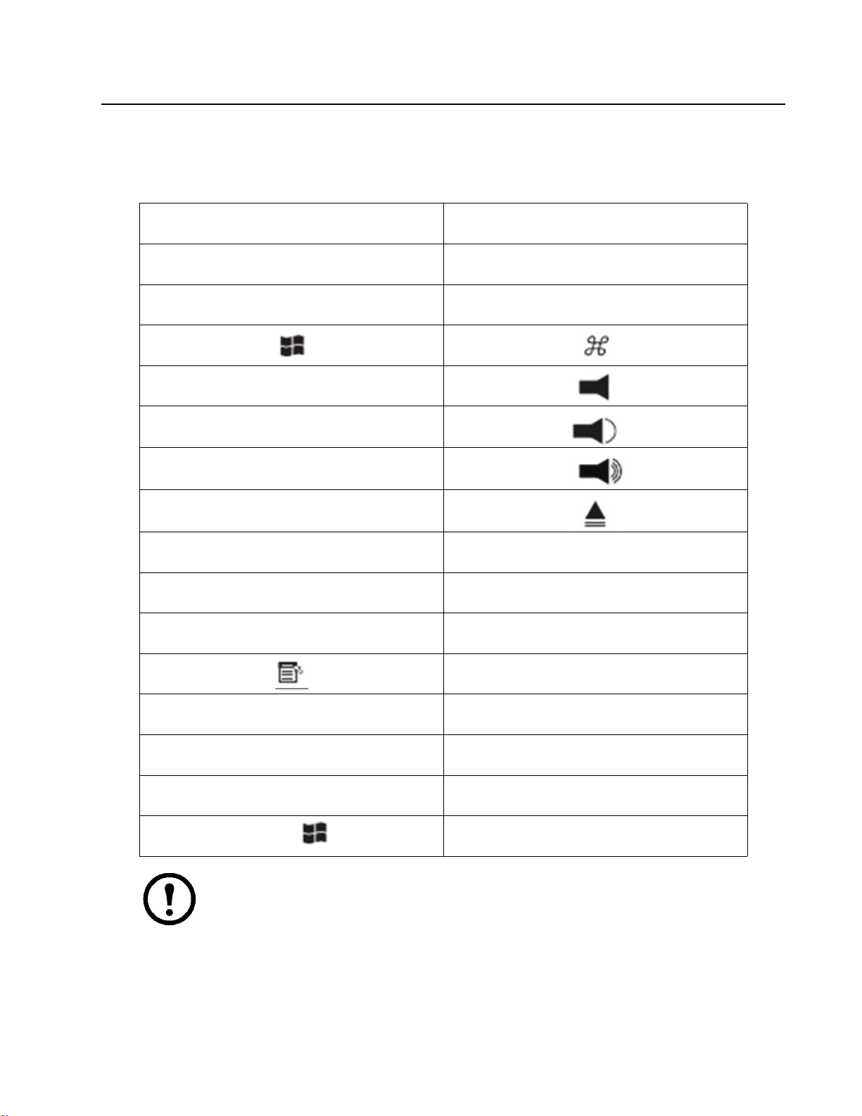
[INSERT]HELP
[CTRL]
Note: When using key combinations, press and release the first key
F15
[CTRL], then press and
release the activation key.
Page 37

Sun Keyboard
29
The PC compatible (101/104 key) keyboard can emulate the functions of the Sun keyboard when the
Control key [
CTRL] is used in conjunction with other keys. The corresponding functions are shown
below.
PC Keyboard Sun Keyboard
[CTRL] [T]
[CTRL] [F2]
[CTRL] [F3]
[CTRL] [F4]
[CTRL] [F5]
[CTRL] [F6]
[CTRL] [F7]
[CTRL] [F8]
[CTRL] [F9]
[CTRL] [F10]
[CTRL] [1]
Stop
Again
Props
Undo
Front
Copy
Open
Paste
Find
Cut
[C
TRL] [2]
TRL] [3]
[C
[CTRL] [4]
TRL] [H]
[C
Help
Compose
Meta
Note: When using key combinations, press and release the first key (
release the activation key.
CTRL), then press and
Page 38

Troubleshooting
30
Overview
Operation problems can be due to a variety of causes. The first step in solving them is to make sure that
all cables are securely attached
Symptom Action
and seated completely in their sockets.
Mouse and/or Keyboard not
responding
All Station IDs display as 01 Station 1 suddenly lost power. Wait a few seconds for the system to
Unplug the cable from the console port, then plug it back in.
re-initialize the station sequence and display the proper IDs.
• Perform a reset on station ID (see “Reset Station IDs” on page 20).
• Unplug the chaining cable, then plug it
OSD Factory Default Settings
Setting Default
OSD Hotkey
Port ID Display Position Upper Left Corner
Port ID Display Duration 3 Seconds
Port ID Display Mode The Port Number plus the Port Name
Scan Duration 5 Seconds
Scan/Skip Mode All
Screen Blanker OFF
Hotkey Command Mode ON
Hotkey
Logout Timeout OFF
Beeper ON
Accessible Ports F (Full Access) For all Users on all Ports
Operation Mode Share
OSD Language English
[SCROLL LOCK] [SCROLL LOCK]
[NUM LOCK] + [-]
back in.
Page 39

Connection Tables
31
The following table indicates the relationship between the number of KVM0108A / KVM0116A units
and the number of computers that they control
KVM0108A
No. Server No. Server No. Server No. Server
1 1-8 9 65 - 72 17 129 - 136 25 193 - 200
2 9 - 16 10 73 - 80 18 137 - 144 26 201- 208
3 17 - 24 11 81 - 88 19 145 - 152 27 209 - 216
4 25 - 32 12 89 - 96 20 153 - 160 28 217 - 224
5 33 - 40 13 97 - 104 21 161 - 168 29 225 - 232
6 41 - 48 14 105 - 112 22 169 - 176 30 233 - 240
7 49- 56 15 113 - 120 23 177- 184 31 241 - 248
8 57 - 64 16 121 - 128 24 185 - 192 32 249 - 256
KVM0116A
No.
1 1 - 16 9 129 - 144 17
2 17 - 32 10 145 - 160 18 273 - 288 26 401 - 416
3 33 - 48 11 161 - 176 19 289 - 304 27 417 - 432
4 49 - 64 12 177 - 192 20 305 - 320 28 433 - 448
5 65 - 80 13 193 - 208 21 321 - 336 29 449 - 464
6 81 - 96 14 209 - 224 22 337 - 352 30 465 - 480
7 97- 112 15 225 - 240 23 353 - 368 31 481 - 496
8 113 - 128 16 241 - 256 24 369 - 384 32 497 - 512
Server No. Server No. Server No. Server
257 - 272
25 385 - 400
Page 40

Specifications
32
Function KVM0108A KVM0116A
Computer
Connections
Connectors Console Ports
Switches Reset 1 x Recessed Pushbutton 1 x Recessed Pushbutton
LEDs Port 16 (Green/Red/Orange) 16 (Green/Red/Orange)
Video 1600x1200 @ 60Hz 1600x1200 @ 60Hz
I/P Rating 100-240VAC, 50/60Hz; 1.0A 100-240VAC, 50/60Hz; 1.0A
Power Consumption 20.6 W Max. 20.6 W Max.
Environment Operating Temp. 32°F - 122°F (0 - 50°C) 32°F - 122°F (0 - 50°C)
Physical
Properties
Direct 8 16
Max 256 512
Keyboard 2 x 6-pin Mini-DIN Female (Purple)
(back)
Video 2 x HDB-15 Female (Blue) 2 x HDB-15 Female (Blue)
Mouse 2 x 6-pin Mini-DIN Female (Green)
Console Ports
(front)
KVM Port 8 x RJ-45 (Black) 16 x RJ-45 (Black)
Power 1 x IEC C14 1 x IEC C14
Chain In/Out Serial Female Serial Female
Power 1 (Blue) 1 (Blue)
Station ID 1 (Orange) 1 (Orange)
Storage Temp. -4°F - 140°F (-20°C to 60°C) -4°F - 140°F (-20°C to 60°C)
Humidity 0 - 80% RH, Non-condensing 0 - 80% RH, Non-condensing
Housing Metal Metal
Weight / Shipping Weight 7 lbs. (3.2 kg) / 10.4 lbs. (4.7 kg) 7 lbs. (3.2 kg) / 10.4 lbs. (4.7 kg)
Dimensions L x W x H 16.6 in (42.4cm) x 9.4 in (23.8cm) x
Rack LCD
Console
2 x USB (Black)
2 x USB (Black)
15 pin DIN Female 15 pin DIN Female
1.67 in (4.25 cm)
(19” 1U)
2 x 6-pin Mini-DIN Female (Purple)
2 x USB T (Black)
2 x 6-pin Mini-DIN Female (Green)
2 x USB (Black)
16.6 in (42.4cm) x 9.4 in (23.8cm) x
1.67 in (4.25 cm)
(19” 1U)
Page 41

Radio Frequency Interference
33
Changes or modifications to this unit not expressly approved by the party responsible
for compliance could void the user’s authority to operate this equipment.
USA—FCC
This equipment has been tested and found to comply with the limits for a Class A digital device,
pursuant to part 15 of the FCC Rules. These limits are designed to provide reasonable protection
against harmful interference when the equipment is operated in a commercial environment. This
equipment generates, uses, and can radiate radio frequency energy and, if not installed and used in
accordance with this user manual, may cause harmful interference to radio communications. Operation
of this equipment in a residential area is likely to cause harmful interference. The user will bear sole
responsibility for correcting such interference.
Canada—ICES
This Class A digital apparatus complies with Canadian ICES-003.
Cet appareil numérique de la classe A est conforme à la norme NMB-003 du Canada.
Japan— VCCI
This is a Class A product based on the standard of the Voluntary Control Council for Interference by
Information Technology Equipment (VCCI). If this equipment is used in a domestic environment,
radio disturbance may occur, in which case, the user may be required to take corrective actions.
この装置は、情報処理装置等電波障害自主規制協議会(VCCI)の基準に基づくクラス A 情報技
装置です。この装置を家庭環境で使用すると、電波妨害を引き起こすことがあります。この場合
術
には、使用者が適切な対策を講ずるように要求されることがあります。
Taiwan—BSMI
警告使用者 :
這是甲類的資訊產品 , 在居住的
環境中使用時 , 可能會造成射頻
干擾 , 在這種情況下 , 使用者會
被要求採取某些適當的對策。
Korean 한국
A 급 기기 ( 업무용 방송통신기기 )
이 기기는 업무용 (A 급 ) 으로 전자파적합등록을 한 기기이오니판매자 또는 사용자는 이 점을 주의하시
기 바라며 , 가정외의지역에서 사용하는 것을 목적으로 합니다 .
Page 42

Australia and New Zealand
34
Warning: This is a Class A product. In a domestic environment this product may cause radio
interference, in which case the user may be required to take adequate measures.
European Union
This product is in conformity with the protection requirements of EU Council Directive 2014/
30/EU on the approximation of the laws of the Member States relating to
compatibility.
This product has been tested and found to comply with the limits for Class A Information
Technology Equipment according to CISPR 32/European Standard EN 55032. The limits for Class A
equipment were derived for commercial and industrial environments to provide a reasonable
protection against interference with licensed communication equipment.
Warning: This is a Class A product. In a domestic environment this product may cause radio
interference, in which case the user may be required to take adequate measures.
electromagnetic
 Loading...