

Page 1

Warranty
• Refer to the online warranty registration reminder guide and complete the online warranty registration.
• Be certain to have the warranty available when requesting repair work.
• Any defects that occur under normal operating conditions during the warranty period will be repaired free of charge.
• Any defects that occur as a result of a natural disaster or inappropriate use, or if the warranty is not presented, the defects will be repaired at cost even
during the warranty per
iod. (See the warranty disclaimer clauses for details.)
• Data stored on your PC may be altered or lost completely following repair. Important data should be backed up on storage media, such as floppy disks
or CD/DVD.
License Agreement
Fujitsu Limited ("Fujitsu") grants you the right to use the software installed on or bundled with this product on the condition that you consent to the
"Conditions of Use" below.
By using the software, you consent to this agreement. Be sure to read the "Software Usage Conditions" below p
rior to using the software. If a software
program bundled with the software includes separate Usage Conditions or a separate License Agreement, these supercede this agreement.
Conditions of Use
1. Software use and copyrights
You may only use the software with this product. In purchasing this product, you only obtain the rights to use the software. The copyrights for the
software belong either to Fujitsu or to the software developer.
2. Backup copies
You are permitted to make a single backup copy of the software.
3. Integration of this software with other software
In the case of products that are intended to be used by integrating this software with other software, you may use part or all of this software by
integrating it with other software in accordance with the instructions described in the relevant manual.
4. Duplication
(1) Duplication of this software is restricted to the conditions in 2 and 3 above. Unless Fujitsu grants duplication rights in a manual or elsewhere,
other software int
egrated with this software may not be copied, except for backup.
Note that duplication may not be possible if the software is copy-protected.
(2) If the software is copied in accordance with the previous clause, the copyright must not be changed, deleted or hidden.
5. Transference to a third party
When transferring the software (including any media and manuals included with this product, as well as backup copies) to a third party, you must
transfer all of the software together with the PC on which the software is in
stalled. You cannot transfer media included with this product to a
third-party separately to the product.
6. Modifications
You may not modify, decompile, disassemble, or otherwise reverse engineer the software.
7. Wallpaper use
You may not modify the logo, or distribute it to a third-party.
8. Scope of warranty
Fujitsu assumes no responsibility for any damage (including, but not limited to, loss of earnings, business disruption, loss of business information
and any other monetary
losses) that occurs due to the use or inability to use the software, except as described in the preceding clause. The same
applies even if Fujitsu is aware of the potential for such losses.
9. Safety-control applications
This software is intended for general applications, including office use, personal use and home use. It was not designed or manufactured for use in
safety-control applications. You must not use this software to implement measures to ensure safety required for safety-control applications.
Safety-control appli
cations refer to applications that require extreme safety, such as the examples below, and are accompanied with the potential for
serious physical risk or direct risk to life if safety is not maintained.
Examples
Nuclear reactor control, flight control systems, airport traffic control, heavy transport logistics, life support, missile launch control
Fujitsu Limited
Microsoft service packs
Microsoft provides service packs to improve the stability of the Microsoft® Windows® operating systems (http://www.microsoft.com).
Using the latest service packs ensures that the stability of the Microsoft
®
Windows® operating system is optimized at the time the service packs are
provided by Microsoft. Consequently, we generally recommend using the latest service packs. However, depending on your environment, service packs
may cause unexpected problems. Therefore, be sure to read the "Readme.txt" file included with the service pack prior to use.
We also recommend backing up your system to protect against installation failur
es.
Page 2

Data backup
Please take the necessary measures for maintaining the data (including the operating system and applications) stored on your co mputer by creating
backups, etc. We do not guarantee the integrity of your data in the event of repair work. Therefore, please back up your data prior to requesting repair
work. We take no responsibility whatever for data maintenance or recovery, or for any damages that occur as a result of the loss of data, expect as
described in the warranty.
Store CD-ROMs and DVD-ROMs included with this product carefully
These disks are necessary for restoring the software installed on this computer to its original condition at the time of purchase.
Liquid crystal display characteristics
• Although liquid crystal displays are manufactured using high-precision technology, dead (black) pixels and constantly-lit (white) pixels may be
visible. This is normal. Be aware that such displays will not be accepted for replacement or return.
• The color tone of the liquid cr
ystal displays used with this product may vary depending on the product and the manufacturing process. Also, slight
color shading may occur as a result of temperature changes and so on. Be aware that this is normal.
• Although ghosting may occur after displaying the same image for long periods, this is not a defect. The ghosting will disappear after a short time. To
prevent this phenomenon, we recommend using the power management feature to automatically turn the display off, or using a screen saver.
• Unevenness
or a small number of dots may become apparent depending on the display conditions. This is normal.
Use of this product in safety-control applications
This product is intended for general applications, including office use, personal use and home use. It was not designed or manufactured for use in
safety-control applications. You must not use this product to implement measures to ensure safety required for applicable safet y-control applications.
Safety-control applications refer to applications that require extreme
safety, such as the examples below, and are accompanied with the potential for
serious physical risk or direct risk to life if safety is not maintained.
• Control of nuclear reactions at nuclear power stations, automatic flight control systems, airport traffic control, heavy transport logistics, medical
equipment for life support, missile launch control in weapons systems, etc.
• Components with a limited lifetime (e.g., LCD display and hard drive).
The life of these components varies according to the frequency
and conditions of use. Replacement of limited-life components is estimated to be
approximately five years when used for about eight hours per day. This is only a guide, and does not guarantee that defects will not occur or that
repairs will be implemented free of charge. Parts may need to be replaced more quickly depending on usage conditions, such as continuous use for a
long period of time.
Continued use of the aluminum electrolytic capacitor used in this product after its life has expired may result in the leakage o
r draining of electrolytes,
or the emission of offensive odors or smoke. Therefore, we recommend replacing it early on. (The customer is responsible for replacing consumable
items, such as battery packs and batteries, with new products.)
• This product is not designed for continuous use of more than 24 hours.
This product should be operated under the following conditions. (During operation) temperature: 10-35°C; relative humidity: 20-80%. (When not in use)
10-60°C & 20-90%. (Condensation should be avoided at all
times.)
This product contains parts specified in the Foreign Exchange and Foreign Trade Control Law. Consequently, it may be necessary to obtain permission to
export this product based on this law.
This product may be damaged by an instantaneous drop in voltage due to lightning, etc. We recommend using an uninterruptible power supply system to
prevent instantaneous drops in voltage.
This product has built-in copyright protection technology that is protected by intellectual property rights and US patents held by Macro
vision Corporation
and other rights holders. The use of this copyright protection technology requires permission from Macrovision Corporation. However, permission has
been obtained for households and other restricted viewer ship. Reverse-engineering and disassembly are prohibited.
The components in this product (e.g., printed wiring boards, CD/DVD drive, hard disk and LCD display) contain trace amounts of heavy metals (lead,
chrome and mercury) and chemicals (antimony and cyanogen).
Page 3

Table of Contents
Information for safe use . . . . . . . . . . . . . . . . . . . . . . . . . . . . . . . . . . . . . . . . . . 4
Regarding the notations in this manual . . . . . . . . . . . . . . . . . . . . . . . . . . . . . . . 4
Chapter 1 Name and function of each of the parts
1 Front of the PC 8
2Side of the PC 9
Left side of the PC . . . . . . . . . . . . . . . . . . . . . . . . . . . . . . . . . . . . . . . . . . . . . 9
Right side of the PC . . . . . . . . . . . . . . . . . . . . . . . . . . . . . . . . . . . . . . . . . . . . 10
3 Back of the PC 11
4 Inside the PC 12
5 Keyboard 13
Chapter 2 Handling your PC
1 Turning the power ON/OFF 16
Check the connections . . . . . . . . . . . . . . . . . . . . . . . . . . . . . . . . . . . . . . . . . . 16
Turning the power on . . . . . . . . . . . . . . . . . . . . . . . . . . . . . . . . . . . . . . . . . . . 17
Turning the power off . . . . . . . . . . . . . . . . . . . . . . . . . . . . . . . . . . . . . . . . . . . 19
Putting the PC in Sleep mode / Resuming . . . . . . . . . . . . . . . . . . . . . . . . . . . . . 22
2 Adjust the volume 24
3 Adjust the brightness of the screen 25
4 Using the One-touch buttons 26
5 Using CD/DVD 27
Disks that can and cannot be used with this PC . . . . . . . . . . . . . . . . . . . . . . . . . 27
Inserting and ejecting disks from the PC . . . . . . . . . . . . . . . . . . . . . . . . . . . . . . 29
6 Using the mouse 33
Regarding the optical mouse . . . . . . . . . . . . . . . . . . . . . . . . . . . . . . . . . . . . . . 33
7 Using the LAN (cable LAN) function 34
This PC’s LAN function . . . . . . . . . . . . . . . . . . . . . . . . . . . . . . . . . . . . . . . . . . 34
An example of connecting when using the Internet . . . . . . . . . . . . . . . . . . . . . . . 34
When using the LAN (cable LAN) . . . . . . . . . . . . . . . . . . . . . . . . . . . . . . . . . . . 35
Chapter 3 Installing/setting up/adding peripherals
1 Using peripherals 38
Peripherals? . . . . . . . . . . . . . . . . . . . . . . . . . . . . . . . . . . . . . . . . . . . . . . . . . 38
Attaching peripherals . . . . . . . . . . . . . . . . . . . . . . . . . . . . . . . . . . . . . . . . . . . 38
Cautions regarding handling peripherals . . . . . . . . . . . . . . . . . . . . . . . . . . . . . . 39
2 Removing and atta ching the connector cover 40
Removing the connector cover . . . . . . . . . . . . . . . . . . . . . . . . . . . . . . . . . . . . . 40
Attaching the connector cover . . . . . . . . . . . . . . . . . . . . . . . . . . . . . . . . . . . . . 41
3 Increasing/replacing the memory 42
Memory insertion location . . . . . . . . . . . . . . . . . . . . . . . . . . . . . . . . . . . . . . . . 42
Memory configuration chart . . . . . . . . . . . . . . . . . . . . . . . . . . . . . . . . . . . . . . . 43
Cautions regarding handling memory . . . . . . . . . . . . . . . . . . . . . . . . . . . . . . . . 44
Increasing the memory . . . . . . . . . . . . . . . . . . . . . . . . . . . . . . . . . . . . . . . . . . 45
Confirming the amount of memory . . . . . . . . . . . . . . . . . . . . . . . . . . . . . . . . . . 51
4 Connecting a USB device 53
Connecting a USB device to the PC unit . . . . . . . . . . . . . . . . . . . . . . . . . . . . . . 53
Removing a USB device . . . . . . . . . . . . . . . . . . . . . . . . . . . . . . . . . . . . . . . . . 54
Chapter 4 Proper care
1 Proper care of your Deskpower 58
Proper care of your PC and attachments . . . . . . . . . . . . . . . . . . . . . . . . . . . . . . 58
Proper care of your LCD display . . . . . . . . . . . . . . . . . . . . . . . . . . . . . . . . . . . . 59
Proper care of your CD/DVD drive . . . . . . . . . . . . . . . . . . . . . . . . . . . . . . . . . . 59
2
Page 4

3
Page 5

Information for safe use
Note
This manual provides information that is important for the safe and proper use of this product.
Please read this manual carefully before using this product. In particular, please carefully read and
understand the “Cautions regarding safety” in “Using this product” prior to using this product.
Also, please be sure to keep this manual handy so that you can refer to it when you are using this
product.
Regarding the notations in this manual
Regarding screen shots and illustrations
The screens and illustrations shown are an example. There may be some differences from the screens
and illustrations depending on the device you are using. Also, the illustrations shown in this manual are
for purposes of explanation and there may be fewer cables shown as connected.
Regarding the symbols for safe usage
There are various illustrations that are used in this manual. The following marks in this manual are
presented for the safe and proper use of this product by you and other people and regarding things that
are to protect you from injury or harm. Those displays and meanings are as follows. Please read and
understand the content
Caution
Also, the following symbols are also used the same as with the display of the pictures above to indicate
the details of what can result in injury or harm.
This indicates that there is the possibility of death or serious personal injury if these
indications are ignored or if it is handled by mistake.
This indicates that there is the possibility of cutting oneself or material damage alone
may result if these indications are ignored or if it is handled by mistake.
The content indicated with a informs you of warnings or urges you to take precaution s.
Items in the symbol or beside it basically display warning details.
The content indicated with a are things which should not be done (prohibited actions).
Items in the symbol or beside it basically display prohibited action details.
The content indicated with a informs you of things that you must definitely f ollow. Items
in the symbol or beside it basically display instruction details.
4
Page 6

Regarding the symbols in this document
Importance
ReferenceReference
The meanings of the symbols used in this manual are as follows.
Importance
Describes things you should be careful of then using this or things you should not do.
Be sure to read this.
Describes operation related items. Please read these as necessary.
Describes where to find references.
Describes a manual you should refer to.
Represents the CD-ROM/DVD-ROM.
Product names
The names of products, etc. in this manual will be displayed abbreviated as follows.
Product name Expressions used in this manual
Windows Vista
Windows Vista
Windows
Laws regarding the movement towards energy savings for
information processing devices
Super multi drive CD/DVD drive
PS/2 keyboard (with one touch buttons, 105 keys) Keyboard or PS/2 keyboard
USB mouse with side scroll functions (optical) Mouse or USB mouse
®
Ultimate Windows or
Windows Vista or
Windows Vista Ultimate
®
Home Premium Windows or
Windows Vista or
Windows Vista Home Premium
®
Internet Explorer® 7 Internet Explorer
Energy saving laws
5
Page 7

Regarding trademarks and copyrights
Microsoft, Windows, Windows Vis ta, Aero, and Internet Explorer are registered trademarks and trademarks of Microsof t Corporation in th e U S
and other countries.
Intel, Intel Core and Celeron are registered trademarks and trademarks of Intel Corporation or its subsidiaries in the US and other countries.
Each of the other product names is the registered trademark of their respective companies.
Other products are the work of each company.
All Rights Reserved, Copyright© FUJITSU LIMITED 2008
Dolby, AC-3, Pro Logic and the Double D symbol are registered trademarks of Dolby Laboratories Inc.
6
Page 8

Chapter 1
Name and function of each
of the parts
This chapter gives details on the name and function of each of
the parts.
Here we will describe you the typical functions of them.
1
Front of the PC
2
Side of the PC
3
Back of the PC
4
Inside the PC
5
Keyboard
. . . . . . . . . . . . . . . . . . . . . . . . . . . . . . . . . . . . . . . . . . 8
. . . . . . . . . . . . . . . . . . . . . . . . . . . . . . . . . . . . . . . . . . . 9
. . . . . . . . . . . . . . . . . . . . . . . . . . . . . . . . . . . . . . . . . . 11
. . . . . . . . . . . . . . . . . . . . . . . . . . . . . . . . . . . . . . . . . . . 12
. . . . . . . . . . . . . . . . . . . . . . . . . . . . . . . . . . . . . . . . . . . . . . 13
7
Page 9
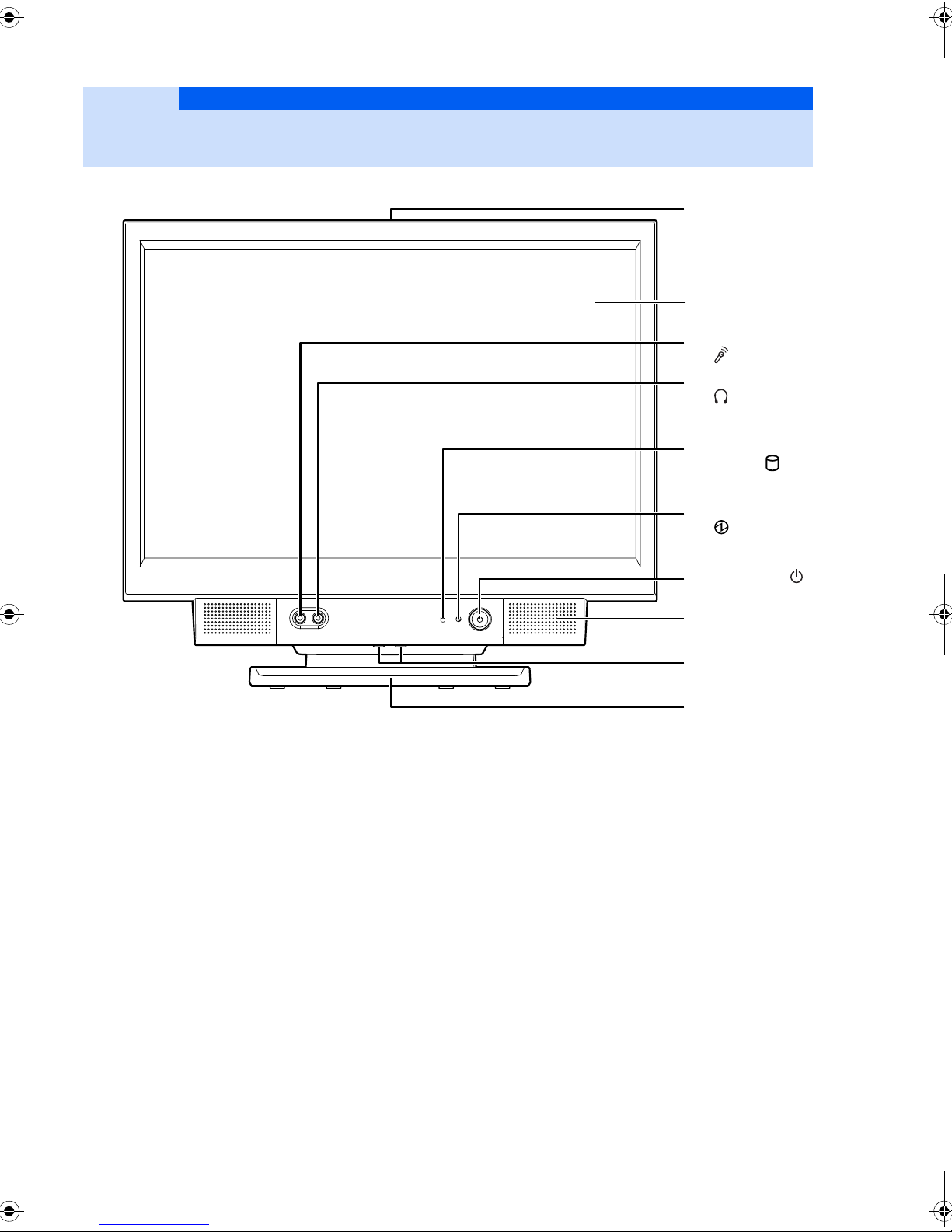
Name and function of each of the parts
5. Disk drive access
indicator ( )
6. Power indicator
()
2. Liquid crystal
display
7. Power switch ( )
8. Speakers
1. Ventilation holes
3. Microphone jack
()
4. Headphone jack
()
9. Brightness
adjustment
button
10. Swivel
1
Front of the PC
1. Ventilation holes
The air vents allow the inside air to exchange with the
outside air to let the heat escape.
2. Liquid crystal display
Displays the PC image.
3. Microphone jack
For connecting a commercial plug in power type
microphone.
4. Headphone jack
For connecting commercial headphones.
5. Disk drive access indicator
This illuminates when data is being read from or written to
the hard disk.
6. Power indicator
This is lighted green when the PC power is turned on and
orange when in sleep mode.
7. Power switch
Press this button to turn the power to the PC on or off.
8. Speakers
Outputs the sound from the PC.
9. Brightness adjustment button
Adjust the brightness of the PC.
10.Swivel
Rotates the PC body left and right to adjust it to an easy to
view angle.
8
Page 10

Name and function of each of the parts
1. Power Inlet
4. Disk drive access indicator
5. CD/DVD eject button
3. Super Multidrive
2. ON/OFF switch
2
Side of the PC
Left side of the PC
1. Power Inlet
This is where you connect the power cable to the main
unit.
2. ON/OFF switch
Switch this to “OFF” to totally shut off th e power to the PC.
“|” is “ON” and “O” is “OFF”.
3. Super Multidrive
You can read and write data to CDs or DVDs and listen to
music CDs.
4. Disk drive access indicator
This light when data is being read from or written to the CD
or DVD.
5. CD/DVD eject button
Press this button to set a disk in the Super multi drive or
eject a disk.
Side of the PC 9
Page 11

Right side of the PC
6. PS/ 2 Keyboard port ( )
4. USB 2.0 port ( )
1. LINE OUT ( )
2. LI NE IN ( )
5. LAN port ( )
3. External VGA port
7. Ventilation holes
1. LINE OUT
This connector is for connecting an audio-in jack of an
audio device.
2. LINE IN
This connector is for connecting an audio-out jack of an
audio device.
3. External VGA port
This connector is for connecting an external display such
as an analog display, etc. sold separately.
4. USB 2.0 port
This connector is for connecting a peripheral device that
uses the USB standard such as a printe r or digit a l camera,
etc.
5. LAN port
This is for connecting a LAN cable.
6. PS/2 Keyboard port
This is for connecting a PS/2 keyboard.
7. Ventilation holes
The air vents allow the inside air to exchange with the
outside air to let the heat escape.
10
Page 12

Name and function of each of the parts
6. Anti-theft lock
installation slot
7. Ventilation holes
3. Ventilation holes
2. Cable hole
8. Cable hole
4. Connector cover
5. Lock button
1. Ventilation holes
3
Back of the PC
1. Ventilation holes
The air vents allow the inside air to exchange with the
outside air to let the heat escape.
2. Cable hole
The cable hole is the hole that allows the USB cables, the
LAN cable and the display cables to pass to the outside.
3. Connector cover
4. Lock button
Press this button when you want to remove the connector
cover.
5. Anti-theft lock installation slot
This is for connecting an anti-theft cable.
Back of the PC 11
Page 13

Name and function of each of the parts
1. Memory slot
4
Inside the PC
1. Memory slot
For installing additional memory.
12
Page 14
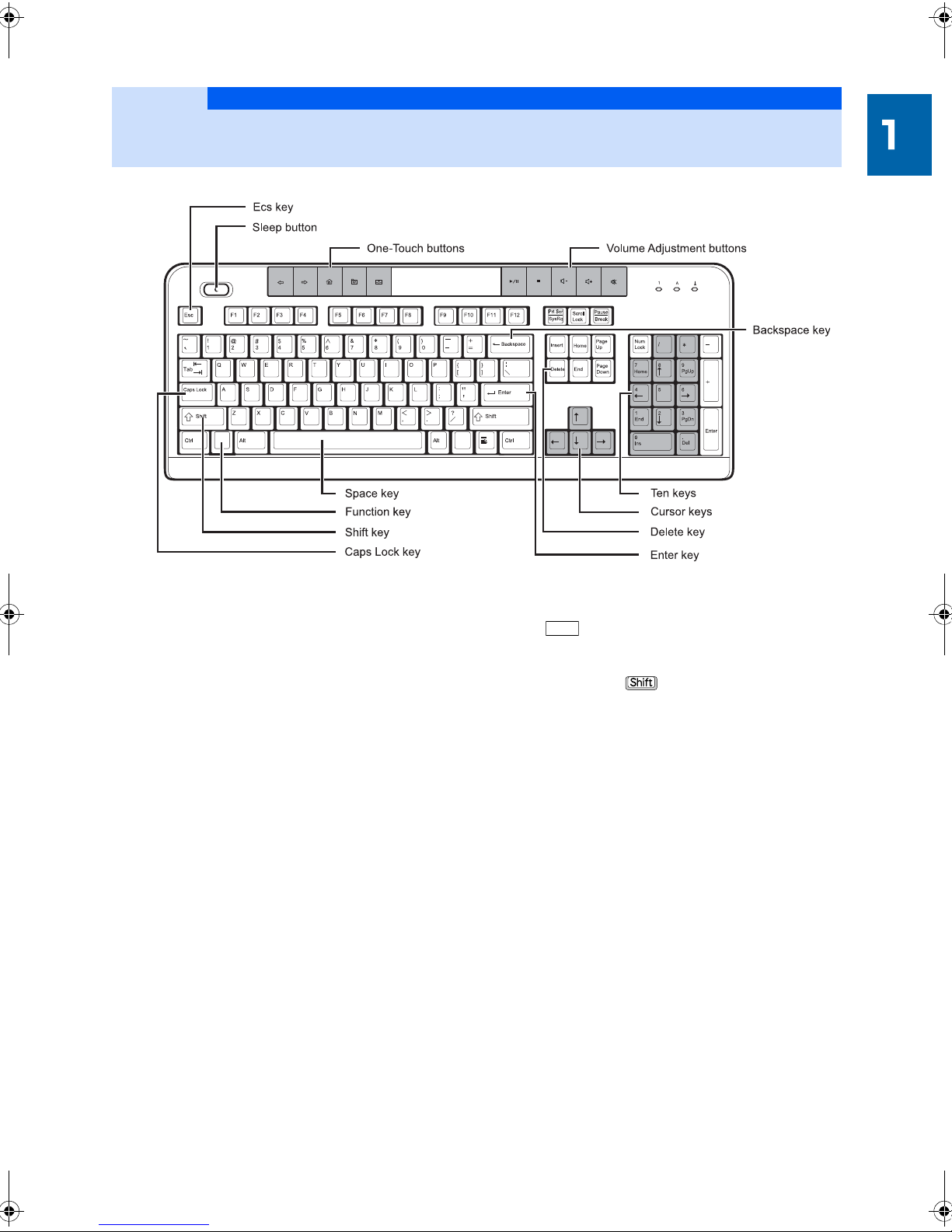
Name and function of each of the parts
5
Keyboard
1. Esc key
This will cancel the current operation.
2. Volume Adjustment buttons
These are used to adjust the PC volume.
3. One-touch buttons
For connecting to the internet, etc.
4. Sleep button
Press this to put the PC in an energy saving state.
5. Delete key
Use this to delete 1 character to the right of the cursor.
Also, this key is used to delete the selected file or icon and
the character string.
6. Backspace key
Deletes the character to the left of the cursor.
7. Space Key
Enters a space.
8. Function key
When you press this key along with a key surr ounded wit h
a , you can move the cursor to the st art of the row or
the beginning of the document.
9. Shift key
When you press along with another character key,
the capital letter or the symbol at the top of the key are
entered.
10.Caps Lock key
This switches between the upper case (capital) and lower
case alphabet.
11.Ten Keys
You can enter numbers or symbols.
12.Enter key
This is used to confirm the text that was entered, etc.
This is also called the Return key.
13.Cursor keys
These move the cursor up and down and left and right.
Keyboard 13
Page 15

Memo
14
Page 16

Chapter 2
Handling your PC
This explains cautionary items that should be confirmed at the
start, and when using.
1
Turning the power ON/OFF
2
Adjust the volume
3
Adjust the brightness of the screen
4
Using the One-touch buttons
5
Using CD/DVD
6
Using the mouse
7
Using the LAN (cable LAN) function
. . . . . . . . . . . . . . . . . . . . . . . . . . . . . . . . . . . . . . . . 24
. . . . . . . . . . . . . . . . . . . . . . . . . . . . . . . . . . . . . . . . . . 27
. . . . . . . . . . . . . . . . . . . . . . . . . . . . . . . . . . . . . . . . . 33
. . . . . . . . . . . . . . . . . . . . . . . . . . . . . . . . . 16
. . . . . . . . . . . . . . . . . . . . . . . . . . . . 25
. . . . . . . . . . . . . . . . . . . . . . . . . . . . . . . . 26
. . . . . . . . . . . . . . . . . . . . . . . . . . . 34
15
Page 17

Note
Handling your PC
Electric outlet
Power supply
cable
Keyboard
USB mouse
1
The method of turning the power ON and OFF is important. Please remember the proper
method.
Turning the power ON/OFF
●
Please do not put your fingers, etc. into the CD/DVD drive tray wh en setting or ejec ting a dis k, etc.
This could result in injury.
●
Please be careful not to cause vibrations or shock when carrying it around when the power is
turned on.
This may result in damage.
Check the connections
Please confirm that the right cables are connected before turning the power on.
16
Page 18
Turning the power on
ImportanceImportance
ON/OFF switch
(The following may differ from your device or condition)
This section gives details on the method for turning on the power along with starting Windows.
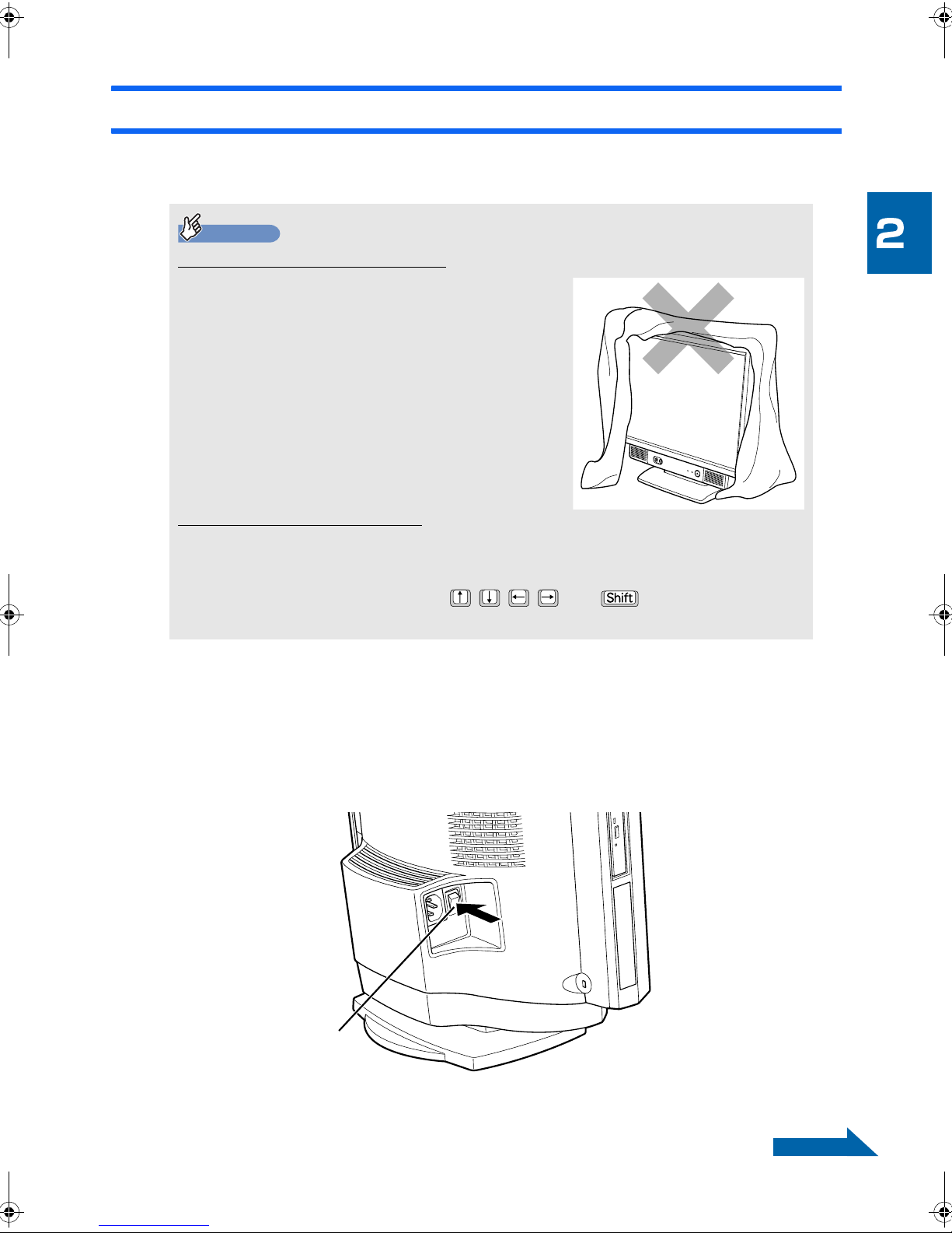
Cautions when turning on the power
●
Please wait at least 10 seconds after turning off the
power before turning it on again.
●
If you are using a cover such as cloth for your PC,
always remember to completely remove it before
turning the power on. The inside of the computer will
heat up which may result in operation problems and
the case may become deformed if you use it with a
cover such as cloth blocking the air vents.
●
Once you have turned the power on, please don’t turn
off the power until the Step5 screen is displayed. I f you
turn off the power bef ore the S tep5 screen i s displayed,
then the PC operation may become unstable.
If you leave the computer running
for a while (about 5 minutes) without doing anything, an animation (screensaver) may be
displayed or the screen may go dark. However, the power is not turned off. The PC is just
operating in an energy saving mode.
If you move the mouse or press any of and on the keyboard, the
screen will return to its original state.
1 Turn on the power to devices connected to the PC.
2 If the Power supply cable is not connected to the Electric outlet, then
plug the Power supply cable into the Electric outlet.
3 Move the ON/OFF switch on the left side of the PC to the “|” position.
■ Left side of the PC
Go to the next page
Turning the power ON/OFF 17
Page 19

Importance
Importance
Power switch
Power indicator
(The screen may differ from your device or condition)
Switch off the Power switch
and then plug the Power supply cable into the outlet. Move the switch to the “|”
position and then the Power indicator will glow for a few seconds and it appears
that the power is on, but this is not a failure.
4 Press the Power switch.
The Power indicator will glow and various characters will appear on the screen. Please wait.
5 Confirm that a screen like this is displayed.
18
Page 20

Turning the power off
CD/DVD eject button
(The following may dif fer from your device or con dition)
Go to the next page
This section gives details on the method for turning the power off along with shutting down Windows.
If you don’t shut down Windows and don’t use your computer, it may enter “Sleep” mode. Please see
“Putting the PC in Sleep mode / Resuming” for information on putting your PC in sleep mode.
1 Finish the work you have been doing.
If you are working on something, save the data you are working on a and quit the software.
For example, if you are working with a word processor then save the text document and quit the
word processor.
If you don’t quit the software
You can proceed with the following operation while the software is running, but a
confirmation message will appear asking if you want to save the data for the work you
are doing. This could be the cause of malfunctions so please quit the software after
you have saved your data.
2 If there is a CD or DVD inserted, pres the CD/DVD eject button on the
left side of the PC and eject it.
■ Left side of the PC
If there is a CD or DVD inserted
You will not be able to eject the CD or DVD once the power is turned off.
Turning the power ON/OFF 19
Page 21

3 Press the Power switch.
Importance
Power Switch
If you wait a little while, Windows will shut down and the power will automatically turn off (the
screen will go dark and the Power indicator will go out). It may take a while for Windows to shut
down (about 20 seconds) so please be patient.
Importance
Please don’t continue to press the Power Switch.
If you press and hold the Power Switch for more than 4 seconds you can force the
power off when Windows will not shut down with the normal method.
20
Page 22

You can also turn off the PC from the “Start” menu.
1. Click (Start) on “Shutdown”.
The PC will turn off (the screen will go dark and the Power indicator will go out).
It may take a while for Windows to shut down (about 20 seconds) so please be
patient.
When the PC power will not turn off.
If the PC stops responding (the mou se and keyboard will not respond, etc.) and won't
turn off, please refer to the following manual.
If it will still not turn off then press and hold the power button for more than 4 seconds
to the force it to turn off.
Please confirm that the Power indicator is of f (the power is of f) once the p ower is o ff. If
the Power/standby lamp is glowing orange it means that the PC is in sleep mode and
the power is not turned off. Press and hol d the power but ton once a gain for more than
4 seconds to turn off the power.
If you won’t be using your PC for a long time
If you won’t be using your PC for a long time then move the Power switch on the left
side of the PC to the “O” position.
4 Turn off the power to devices connected to the PC.
Turning the power ON/OFF 21
Page 23

Putting the PC in Sleep mode / Resuming
(The screen may differ from your device or condition)
If you put your PC in sleep mode instead of turning the power off when you are not going to be using it
for a while then you will be able to start using it very quickly next time you want to use it.
Sleep mode includes sleep and hibernate states. We will explain how to put your PC to sleep and how
to resume from sleep here.
Turn off your computer in the following cases
●
When you will not be using the PC for a long time
●
When the PC is operating slowly or it is not operating normally.
Please turn off the PC and restart it again.
The PC will enter Sleep mode
1 Click (Start) .
The PC will go to sleep. The Power indicator will glow orange when the PC is sleeping.
22
Page 24

Resuming from sleep
1 Press the Power Switch on the main unit.
The PC will resume from the sleep state. Please don’t continue to press the Power Switch for
more than 4 seconds. The PC power will turn off.
Regarding sleep
●
The PC power is not off but the current work data is saved in the memory and the PC is in a
standby state. Only a little power is used to save the data that has been saved in the memory
when in sleep mode.
●
Do not try and resume immediately after the PC goes to sleep.
Please always wait at least 10 seconds before resuming.
Turning the power ON/OFF 23
Page 25

Handling your PC
(The illustration may differ from your device or condition)
2
This section gives details on the method for adjusting the volume using the volume
adjustment buttons on the keyboard.
The volume adjustment buttons on the keyboard will operate when Windows is running.
Adjust the volume
1 Press the volume adjustment buttons on the top of the keyboard and
adjust the volume to an appropriate level.
Pressing the volume (-) button will reduce the volume and pressing the volume (+) button will
increase the volume.
Pressing the Mute button will mute the sound and the taskbar notification display in the lower
right of the screen will change to . Pressing it again will return to the previous volume and the
display will also change back to .
Play/Pause
Play file in the current track. Press again to puase.
Stop
Stop the playing.
Volume down(-)
Lower the volume.
24
Volume up(+)
Raise the volume.
Mute
Mute or resume sound output.
Page 26

Handling your PC
Brightness adjustment button (-)
(The illustration may differ from your device or condition)
Brightness adjustment button (+)
Dark
Bright
(The screen may differ from your device or condition)
3
This section gives details on the method for adjusting the brightness of the LCD display.
Press the brightness adjustment buttons the front of the PC and you can change the
brightness of the LCD display.
Adjust the brightness of the screen
1 Press the brightness adjustment buttons on the front of the PC and
adjust the brightness to an appropriate level.
Pressing the brightness (+) button will make it brighter and pressing the brightness (-) button will
make it darker.
An indicator will be displayed at the bottom of the screen when the brightness is being adjusted.
Adjust the brightness of the screen 25
Page 27

One-touch buttons are used to call the variou s PC functions. You can run software or receive e -mails simply by pushin g the One-touch buttons.
Handling your PC
4
Back
To return to the last page you viewed.
Forward
To view the next page you viewed before.
Web/Home
To start your Microsoft Internet Expl orer 5.0 and bring up
Using the One-touch buttons
the home page you set.
My Favorites
To select a web page from your list of favorites.
Email
To open the default program you use for mail.
Sleep
To put your system to sleep (power-saving) mode.
If the “User account control” window is displayed
If the “User account control” window is dis pla yed when you press a One-t ouch butt on, plea se cli ck
on “Continue”. Enter the pas sword for that account an d click “OK” if “Conti nue” is not display ed and
“Administrator account” is displayed.
26
Page 28

Handling your PC
5
Using CD/DVD
This section gives details on the method for setting a usable disk in the PC or ejecting it.
Disks that can and cannot be used with this PC
Usable disks
This PC can use 8cm CDs as well as 12cm CDs and DVDs.
Still, there are various types of CDs and DVDs. The CDs and DVDs that can be used in this PC are
listed below.
Type Pronunciation example
CD CD-ROM
CD-DA (Music CD)
Photo-CD
Video CD
CD-R
CD-RW
DVD DVD-ROM
DVD-VIDEO
DVD+R
DVD+RW
DVD+R DL
DVD-R
DVD-RW
DVD-R DL
DVD-RAM (Note)
CD-ROM
CD-DA
Photo-CD
Video CD
CD-R
CD-RW
CD-Rewritable
DVD-ROM
DVD-Video
DVD plus R
DVD plus RW
DVD plus R Double Layer
DVD-R
DVD Minus R
DVD RW
DVD minus RW
DVD-R double layer
DVD minus R double layer
DVD-RAM
Note: FIt is necessary to format a DVD-RAM if it is to be used.
Using CD/DVD 27
Page 29

ImportanceImportance
Regarding DVD-RAM
●
Please purchase the cartridge-less type or the type where the disk can be ejected from the
cartridge. The type that is used while in the cartridge (Type 1) can’t be used. Also, please
don’t force eject it and use it.
●
You can’t use 2.6GB or 5.2GB disks.
●
DVD-RAM2 (12X/16X) can’t be used.
Unusable disks
Please do not use the following disks.
●
Disks that are not round (shaped disks such as star shaped or card shaped)
This PC can only use round disks.
Using shaped disks that are not round may cause damage.
Damage caused by using shaped disks will not be covered by the warranty.
●
Extra thick DVD media
DVD standards require that the media thickness be between 1.14mm and 1.5mm.
Damage may result if the recording side is too thin, etc. or if any part of the media is thicker than the
standards.
Damage caused by using disks that do not meet standards will not be covered by the warranty.
●
Commercial cleaning disks, lens cleaners
Please do not use commercial cleaning disks or lens cleaners because they can actually gather the dirt
and can make the lens in the CD/DVD drive dirty and make it unusable.
●
Disks that do not have a hole in the center.
●
Scratched or cracked disks
Damage to the inside of the drive may result from using a scratched or cracked disk.
28
Page 30

Inserting and ejecting disks from the PC
Note
CD/DVD eject button
(The following may differ from your device or condition)
Set the disk
Disks can be set in the PC when the power is turned on.
●
Please do not put your fingers, etc. into the CD/DVD drive t ray when setting or ej ecting a disk, et c.
This could result in injury.
1 Press the CD/DVD eject button on the left side of the PC.
The disk tray will eject.
■ Left side of the PC
Using CD/DVD 29
Page 31

2 Pull out the tray by hand.
Tray
Tray
Spindle
Grab the tray with your hand and pull it out.
■ Left side of the PC
3 Set the disk in the PC
With the disk label facing you (in the case of a double sided DVD-RAM, have the side that the
data is read from/written to away from you) line up t he spind le i n the t ray wit h t he hole in t he disk
and press the disk on until you hear a “click”. Please support the tray with your hand so that this
does not tip over the PC.
The disk may not play and you may not be able to eject the disk if this is not done properly.
■ Left side of the PC
30
Page 32

4 Press the tray in by hand until you hear a “click”.
CD access lamp
(The screen may differ from your device or condition)
Go to the next page
Slide the tray into the PC. The CD access lamp will light when the disk is set. Proceed to the
following operation once you have confirmed that the CD access lamp is no longer lit.
The disk may run automatically depending on the disk.
■ Left side of the PC
If the “Auto play” window is displayed
Please click if the “Auto play” window is displayed after the disk is set.
Using CD/DVD 31
Page 33

Note
Remove the disc
Disks can be ejected from the PC when the power is turned on.
●
Please do not put your fingers, etc. into t he CD/DVD drive tray wh en setting or eject ing a disk, e tc.
This could result in injury.
1 Quit any software that is using the disk.
2 Confirm that the CD access lamp is not lighted and the press the CD/
DVD eject button on the left side of the PC.
The disk tray will with the set CD will pop out a bit.
3 Pull out the tray by hand.
Grab the tray with your hand and pull it out.
4 Remove the disc.
5 Press the tray in by hand until you hear a “click”.
32
Page 34

Handling your PC
Reading
Sensor
6
Using the mouse
This section gives details on the USB mouse (optical).
Regarding the optical mouse
Mouse layout
The optical mouse has an optical sensor located on the bottom. The sensor on the bottom of the mouse
detects the shadows in the optical beam output from the bottom of the mouse when it is used on a desk,
which causes the on-screen mouse pointer to move.
Important points when using an optical mouse
The optical mouse works not only on top of a desk, but you can also use it on top of paper, however,
it may not move properly if used on the following surfaces.
●
A reflective surface such as a mirror or glass
●
A glossy surface
●
A surface with alternating light and dark areas such as stripes or a pattern (such as wood grain)
●
An item printed in halftones, or a repetition of a similar pattern
The mouse movement is recognized even if the optical sensor is not touching the desk so a mouse pad
is not required, but the mouse itself is touching the desk so it is recommended that you use a mouse
pad on a desk that could be scratched easily.
It is recommended that you use a bright solid color mouse pad if you are going to use a mouse pad.
There are mouse pads on the market that are for an optical mouse.
Using the mouse 33
Page 35

Handling your PC
Internet
Broadband modems such as
ADSL modem or cable modem
LAN cable
7
This section introduces the LAN connector that is used for the LAN (cable LAN) function will
be explained.
Here we will take the example of connecting primarily to the internet.
Using the LAN (cable LAN) function
This PC’ s LAN function
The following are standard on this PC.
●
LAN connector (for LAN cable)
1000BASE-T/100BASE-TX/10BASE-T compliant
An example of connecting when using the Internet
The following illustration shows an example the PC is connected to a broadband modem using a LAN
cable. The device you will use will differ depending on the structure of the network so please purchase
the item that is suitable for your network.
34
Page 36

When using the LAN (cable LAN)
This section tells you what is required when using a LAN (cable LAN).
Here we will take the example of connecting the PC to the broadband internet.
Prepare what is necessary
The following items will be required in addition to the PC.
●
Broadband Modem
ADSL modem, cable modem, etc. which will be diffe rent depending on your internet line and provider.
●
Router
This is a device that is set up as an intermediary between dif ferent networks and works to make sure that
the data that is flowing across the network arrives at the target location (a PC or printer).
Generally this is used to connect a LAN and an outside network (Internet).
It is required to connect multiple PCs. It may also be equipped with a broadband modem.
Furthermore, please use a device that supports 1000BASE-T to do 1000BASE-T communications.
●
Hub
This is a device that is used to relay cables on the network.
It is required to connect multiple PCs. It may also be built in to a router.
Please use a device that supports 1000BASE-T to do 1000BASE-T communications.
●
LAN cable (straight type)
It is necessary that these match the speed of your network. Please read the manuals for the devices on
the network you will connect to and prepare the required items.
Please use enhanced category 5 cable (Cat5E) or better cable for 1000BASDE-T communications.
Settings for using the LAN
Connect the LAN cable to the required device and set up the network in order to use the LAN. Please
follow the manual provided by your provider in order to set up the device and connect to the Internet.
Using the LAN (cable LAN) function 35
Page 37

36
Page 38

Chapter 3
Installing/setting up/adding
peripherals
Cautions regarding using peripherals and adding memory will be
explained. Please read the parts you need.
1
Using peripherals
2
Removing and attaching the connector cover
3
Increasing/replacing the memory
4
Connecting a USB device
. . . . . . . . . . . . . . . . . . . . . . . . . . . . . . . . . . . . . . . . 38
. . . . . . . . . . . . . . . . . . . . 40
. . . . . . . . . . . . . . . . . . . . . . . . . . . . . 42
. . . . . . . . . . . . . . . . . . . . . . . . . . . . . . . . . . 53
37
Page 39

Caution
Installing/setting u p/adding p eripheral s
1
This section gives details on wha t you should know about usin g peripherals such as memo ry etc.
Using peripherals
●
Please turn off the PC and the devices that are connected to it and unplug the power cord from
the outlet before attaching or removing any peripherals.
Failure to follow this procedure may result in electric shock, fire or injury.
●
Please read this manual and properly connect the peripheral cable.
Electric shock or fire may result if it is used with the cables connected improperly. Also, this may
result in a breakdown of the PC or the peripheral.
Peripherals?
These are memory, printers, digital cameras or other device. These can be installed in the PC or be
connected to the PC using one of the various connectors.
It will be necessary to remove the connector cover if the peripherals are to be installed inside the PC or
connected to the right side. Please see “Removing and attaching the connector cover” for the method of
removing and attaching the connector cover.
Attaching peripherals
You can do more with your computer, such as increasing the processing power by adding memory or
printing by connecting a printer.
Also, you can read the photos you have taken with a digital camera into the PC or send them by e-mail.
38
Page 40

Cautions regarding handling peripherals
Please be careful of the following when adding peripherals.
●
We recommend using peripherals that are produced by our company.
If you connect peripherals not made by our comp any when peripherals made by our company are
available and they do not work properly or damage your PC then it will not be covered by the warranty.
If our company does not make the periph erals then pl ease confirm with the maker of t hat peripheral that it
will work with this PC.
●
Please confirm that the drivers that come with the peripheral and will be used are compatible
with Windows.
You will not be able to use that peripheral if the drivers used by that peripheral are not supported by
Windows. Please be sure to prepare items that are supported by Windows.
●
If the drivers, etc. are supplied on a floppy disk
Depending on the peripheral, the drivers may be provided on a floppy disk. In that case, you can
purchase the optional FDD unit (USB) and install the drivers.
●
Please use peripherals that support ACPI
This PC performs power management using ACPI (1 of the control standards for sa ving energy) so it is
necessary that any peripherals also support ACPI.
If you use a peripheral that does not support ACPI then additional devices or the PC may stop operating
correctly. Please contact the pe ripheral maker to confirm if it supports ACPI.
Also, the ACPI mode of this PC is set as sleep (ACPI S3).
●
Please only connect one peripheral at a time.
If you install more than 1 peripheral at the same time then the installation of the drivers may not proceed
properly. Please confirm proper operation after one peripheral has been attached and then attach the
other peripheral.
●
Turn off the power to the connected devices and the PC.
Please always unplug the power cord from the outlet for safety. There may be an electrical charge flowing
in the computer even when the power has been di sco nnected . Refer to “Turning the power of f” for d et a ils
on how to turn the power off.
●
Please do not perform the operation immediately after turning off the power.
The equipment inside the PC may be hot immediately after the power is turned off. Please start the
operation after waiting 10 minutes from the time the power is turned off and the power cord is unplugged
from the outlet.
●
Please do not disassemble the power supply.
The power supply is the box shaped part on the bottom inside the PC.
●
Please be careful handling the equipment and various cables inside the PC.
Please don’t damage or work it. Also, please don’t twist it or bend it extremely.
●
Please do the job on a soft cloth.
If you work directly on a hard surface, the PC body may get scratched.
●
Please be careful of static electricity.
The internal peripherals may have the circuit board or devices exposed. These part s may be damaged by
static electricity occurring from a human body. Before handling, please discharge any static electricity by
touching your hand once to a large metallic object.
●
Please don’t touch your hand to the surface of the circuit board or the solder portion and
connected components.
Please hold it using the edge of the board or using a metal part.
●
Regarding the peripheral’s power
In general, the peripherals will receive power before the PC recei ves power, however there are some that
will receive power after the PC. Refer to the peripheral manual.
Using peripherals 39
Page 41

Installing/setting u p/adding p eripheral s
ImportanceImportance
Connector cover
Lock button
(The following may differ from your device or condition)
Removing and attaching the
2
connector cover
This section gives details on the method for removing peripherals.
Please print the process for attaching peripherals.
“It is convenient to print this page” is mentioned at the top of the corresponding page in the
“On-line manual” if there are peripherals that will require the power to be turned off during the
process. Please print the corresponding pages from the “On-line manual” before starting the
process and review them.
Please see “Increasing/replacing the memory” for information on memory.
Removing the connector cover
1 Press the lock button while pressing on the connector cover on the
right side of the PC.
Remove the connector cover.
40
Page 42

Attaching the connector cover
ImportanceImportance
1 Align the pins (8 places) on the connector cover that correspond to
8 holes in the PC body and attach it by sliding up.
Please align the pins with the holes when attaching the connector cover.
Please confirm that all of the pins on the connector cover are going into the holes in the PC body.
The areas that are enclosed in the dotted lines in the following illustration are the pins and holes.
Removing and attaching the connector cover 41
Page 43

Installing/setting u p/adding p eripheral s
Memory
Slot 2
Memory
Slot 1
(The illustration may differ from your device or condition)
3
You can increase the processing power of the PC by increasing the memory that can be
added to the PC. This section gives details on the method for increasing the memory.
Increasing/replacing the memory
Memory insertion location
The memory is installed in the memory slots inside the PC.
42
Page 44

Memory configuration chart
Please confirm the memory amount and the memory slot configuration on the following chart.
The PC may not operate properly if you use a configuration other than that listed in the chart.
■ If 2GB of memory is selected using K50Y
Total amount Memory slot 1 Memory slot 2
2GB (When purchased/maximum) 1GB 1GB
■ If 1GB of memory is selected using K50Y
Total amount Memory slot 1 Memory slot 2
1GB (When purchased) 512MB 512MB
2GB (Maximum) 1GB [Note 1] [Note 2] 1GB [Note 1] [Note 2]
Note 1: The memory that was previously installed will be exchanged.
Note 2 : Please install a set of 2 pieces of the same size memory that is made by our company.
Increasing/replacing the memory 43
Page 45

Cautions regarding handling memory
Caution
Note
Do not touch this part.
Memory
●
Please turn off the PC and the devices that are connected to it and unplug the power cord from
the outlet before installing or exchanging memory .
Failure to follow this procedure may result in electric shock, fire or injury.
●
Please do not remove screws from any locations other than those indicated when installing or
exchanging the memory.
There is a risk of injury if you remove screws from places other than those indicated.
Also, this may result in damage.
●
Please do not touch anything sticking up from the surface of the circuit board with your hand.
There is a risk of injury. Also, this may result in damage.
●
Please do not leave the removed memory in a place where small children can play with it.
There is a risk of injury if a small child were to play with it and put it in their mouth.
Also, this may result in damage.
Cautions when installing memory
●
Please be sure to insert the memory after confirming the insertion direction when installing memory .
The memory will not seat completely if it is mistakenly inserted in the wrong direction or it is inserted
incompletely which can result in a failure.
●
Memory is structured in such a way that it is very weak with regards to static electricity and it can be
destroyed by the static electricity from a human body. Before handling the memory, please
discharge any static electricity by touching your hand once to a metallic object.
●
Please do not insert the memory multiple times. This may result in damage.
●
Please do not touch the connectors or the IC portion of the memory. Also, do not use a strong force
with the memory.
●
If you cannot install the memory well, try once again to install the memory after removing it rather
than forcefully trying to install the memory.
●
Please hold the memory with both hands as indicated in the illustration below. Please be sure to
never touch the terminals which are the parts with the gold colored lines.
●
There may be an electrical charge flowing in the computer even when the power has been
disconnected. Please always confirm that the power cord has been unplugged fro m the outlet.
44
Page 46

Increasing the memory
ImportanceImportance
(The following may differ from your devic e or condition)
Caution
●
When taking the PC cover off such as when installing or removing memory, make sure that the
power is turned off to the PC and to any con nected devices and once the power cord is unplugged
from the outlet and remove the cover after a short time has passed. There is a chance of electric
shock when lightning occurs.
The method for increasing memory is described below.
1 Turn off the power to the PC and any connected peripherals and
unplug the power cord from the outlet.
2 Place the PC body so that the display is upright.
3 Place the PC flat so that the back of the PC is facing up.
Place it so that the top of the PC is closest to you.
Please work with a thick soft cloth spread out u nder t he uni t. Plea se b e esp eciall y c arefu l tha t no
sharp object contacts the LCD display.
The PC is heavy
Please take sufficient care that not to drop or cause an impact when laying the PC down flat.
Increasing/replacing the memory 45
Page 47

4 Please refer to “Removing the connector cover” and remove the
connector cover from the right side of the PC.
5 Remove the upper cover.
Please slide the parts that have “PULL” printed on t hem to the right and pull them toward you.
6 Remove the main cover.
Remove the screws (2 places) from the top of the PC, press on the bottom and slide the main
cover towards you.
Depending on the equipment you are using, it may feel difficult when removing the main cover.
46
Page 48

7 Please confirm the location for installing the memory and the memory
ImportanceImportance
Notch
Long
Go to the next page
amount and configuration.
Refer to “Memory insertion location” for detai ls on where to inst al l the memory. Refer to “Memory
configuration chart” for details on the capacity and configuration of the memory.
8 Remove the memory.
The memory will slant up slightly when you push out the clips on both sides of the memory right
and left. Grab the memory with both hands on the edges and pull it up slantingly to remove it from
the slot.
Cautions when removing the memory
●
Please be careful to not pinch your fingers when pressing the clip s on both sid es
of the memory slot to the outside.
●
Please be careful because if you press the clips to the outside too forcefully the
memory can fly out which can result in damage.
9 Install the memory into the memory slot.
Install the memory first in Slot 1 and then in Slot 2.
Insert the memory with the long side from the edge to th e notch cut in the termina l side fa cing the
bottom and press straight down starting from the fr ont of the memory slot.
Increasing/replacing the memory 47
Page 49

10 Press down until you hear a “click”.
Importance
Clip
Please confirm that the clips on both sides fit firmly when pressing on the memory.
Importance
When installing the memory
●
Please install the memory holding it on the edges wit h both han ds, bein g careful
not to touch the terminals or IC components.
●
Please do not touch the connectors or the IC portion of the memory. Also, do not
use a strong force with the memory.
●
If you cannot install the memory well, try once again to install the memory after
removing it rather than forcefully trying to install the memory. If you try to force
the memory when installing it you may damage the memory or the connectors.
Regarding the direction of the memory
Please be careful to confirm the direction an d install it properly. You may damage it
if you force it when installing.
11 Attach the main cover.
Align the unit cover with the lines and lower it straight down. Then slide it toward the PC till the
PC cover and the pins on the PC meet.
48
Page 50

12 Replace the screws (2 places) that you removed in Step 6
Go to the next page
13 Install the upper cover.
Line up the line in the middle of the cover with the line in the middle of the PC and lower it and
slide it to the left.
14 Please refer to “Attaching the connector cover” and remove the
connector cover from the right side of the PC.
Increasing/replacing the memory 49
Page 51

15 Stand up the PC unit.
Importance
Once the PC is standing up, adjust the display to a viewing angle that is easy to see.
Importance
The PC is heavy
Please take sufficient care that not to drop or cause an impact when standing the
PC up.
Next, check the amount of memory to make sure that the memory is installed correctly.
50
Page 52

Confirming the amount of memory
Amount of
memory
(The screen may differ from your device or condition)
Once the memory is installed, please confirm that the memory that was added is able to be used.
Please always perform this confirmation operation after the cover has been attached.
1 Connecting power to the computer.
Please see “Turning the power on” for information on memory.
When nothing is displayed on the screen
If the memory is not installed correctly nothing may be displayed on the screen when
the power is turned on to the PC.
In this case, press and hold the power but ton for at least 4 second to turn of f the power
to the PC, unplug the power cord then reinstall the memory.
2 Click on (Start) “Control Panel” “System and Maintenance”
“System” in that order.
3 Please confirm that the value indicated in the circled area has
increased by the amount of memory you added.
The amount of memory displayed will differ depending on the PC used.
Increasing/replacing the memory 51
Page 53

4 Click .
Please confirm the following items if the amount of memory has not increased.
●
Is the type of memory installed a type that this computer can use?
Refer to “Memory configuration chart”
●
Is the memory securely seated in the memory slot?
Refer to “Increasing the memory”
●
Is it installed in the proper slot?
Refer to “Memory insertion location”
●
Is the memory in the proper configuration?
Refer to “Memory configuration chart”
52
Page 54

Installing/setting up/add ing periphera ls
USB cable
USB connector
(The illustration may differ from your device or condition)
4
This section gives details on what attentions should be paid when using USB devices and
how to connect them.
Connecting a USB device
Connecting a USB device to the PC unit
Cautions when connecting a USB device
●
Depending on the USB device, you may need to turn off t he power to the PC when you are
connecting or removing them. Please refer to the USB device manual for details.
●
If you are using an optional FDD unit (USB) you wil l need to t urn of f th e power when conne cting
or removing it.
●
If you will be inserting or removing a USB device without turning of f the power, please leave it for
about 5 seconds.
●
Depending on the USB device, the light on the USB device may continue to glow or flash even
after the power for the PC is turned off.
1 Connect the USB cable to the USB device.
Please refer to the USB device manual regarding the method for con necting the USB cable.
2 Please refer to “Removing the connector cover” and remove the
connector cover from the right side of the PC.
3 Connect the cable from the USB device to the USB connector on the
right side of the PC.
Insert the USB cable with the side of the connector facing right.
Once the cable is connected, if the “Hardware installation” window appears, click “Con ti nue ” and
continue installing the drivers.
■ Right side of the PC
Connecting a USB device 53
Page 55

4 Please refer to “Attaching the connector cover” and remove the
connector cover from the right side of the PC.
5 Install the drivers.
There are some USB devices that do not require drivers and may work by just connecting t hem to
the PC. Please refer to the USB device manual for details.
If they don’t operate normally
Remove the USB device if it does not operate properly once you have turned the power
on to the PC. Then, try connecting it again once you have turn the PC power off.
Removing a USB device
The operation may be different depending on the condition of the PC.
●
Please follow Step 1 if the power is on.
●
Please follow Step 3 if the power is off.
If the power is turned on
Please refer to the USB device manual for the step s to be followed when removing a powered USB
device.
1 Click on (Safely Remove Hardware) in the taskbar notification area
in the lower right of the screen.
2 Click on “Safely remove [the USB device you are using]”.
The message “Safe to remove hardware” will be displayed.
3 Remove the cable from the USB device from the USB connector.
54
Page 56

Connecting a USB device 55
Page 57

Memo
56
Page 58

Proper care
1
Proper care of your Deskpower
Chapter 4
. . . . . . . . . . . . . . . . . . . . . . . . . . . . . . 58
57
Page 59

Caution
Proper care
ImportanceImportance
1
Here we will give details on the daily maintenance so that you can enjoy using your
Deskpower without any trouble.
Proper care of your Deskpower
●
Please turn off the PC and the devices that are connected to it and unplug the power cord from
the outlet before maintaining it.
Failure to follow this procedure may result in electric shock, fire or injury.
Proper care of your PC and attachments
Please do not use the following:
Never use various strong and volatile cleaners such as thinner and benzene or chemically
treated cleaning cloths.
Please do not use commercial cleaners that use alcohol as one of the ingred ients.
Please clean regularly to make sure the PC air vents don’t become clogged with dust.
Please lightly wipe off the PC unit, the mouse and the keyboard, etc. with a clean dry cloth when dirty.
If they are really dirty, please clean them with a cloth with water or mild detergent after it has been
thoroughly wrung out. If you are cleaning with a detergent, please follow up and wipe off all of the
detergent with a wet cloth that has been thoroughly wrung out. Please also be careful that no water
gets into the PC unit, the keyboard or the mouse when cleaning.
When the keyboard or the space between the keys gets dirty, don’t blow it off, but instead use a soft
brush to remove the dirt. If you blow it off then the dirt will get inside the keyboard which can result in
failures. Also, don’t use a vacuum cleaner and use strong suction on the keys.
58
Page 60

Proper care of your LCD display
ImportanceImportance
Soft cloth
Cleaner
Cleaners that contains alkal i
Thinner
Benzine
Alcohol
Please do not use the following:
Commercial cleaners that contain the following ingredients may damage the surface coating or
the cover and using them must be avoided.
Cleaners that contain alkaline substance.
Cleaners that contain surfactant
Cleaners that contain alcohol
Strong volatile compo unds such as thinner or benzene
Cleaners that contain abrasive
Chemical cloths
etc.
Please wipe your LCD with a soft cloth such as gauze.
Proper care of your CD/DVD drive
Please do not use commercial cleaning disks or lens cleaners because they can actually gather the dirt
and can make the lens in the CD/DVD drive dirty. This can cause breakdowns so be absolutely sure not
to use them.
Wiping off fingerprints or dust on the bottom of the disk can remedy the problem when you are not able
to read well from a disk.
The cleaning method will vary depending on the type of disk. Please see the disk manual or label, etc.
for more details.
Proper care of your Deskpower 59
Page 61

Memo
60
 Loading...