

Page 1
USER'S GUIDE
imageRAID® Series
STORAGE SYSTEMS
Page 2

Page 3

USER'S GUIDE
imageRAID® Series
STORAGE SYSTEMS
Page 4

Fujitsu Europe Limited
Restricted Rights and Liability
No part of this manual may be reproduced, stored in a retrieval system, or transmitted, in any form or by any
means, electronic, mechanical, recording, or otherwise, in whole or part, without prior written permission from
Fujitsu Europe Limited.
Fujitsu Europe Limited shall not be liable for any damages or for the loss of any information resulting from the
performance or use of the information contained herein. Your rights to the software are governed by the license
agreement included with any accompanying software. Fujitsu Europe Limited reserves the right to periodically
revise this manual without notice. Product features and specifications described are subject to change without
notice.
Copyright
Fujitsu Europe Limited
Hayes Park Central
Hayes End Road
Hayes, Middlesex, England UB4 8FE
Copyright © 2003 Fujitsu Europe Limited. All rights reserved.
imageRAID and the imageRAID logo are registered trademarks of Fujitsu Europe Limited, Fujitsu is a registered
trademark of Fujitsu Limited.
Other company and product names herein may be trademarks or registered trademarks of their respective
companies.
Agency Notes
WARNING: Drives and controller/adapter cards described in this manual should only be installed in UL-listed and CSA
certified computers that give specific instructions on the installation and removal of accessory cards (refer to your
computer installation manual for proper instructions).
ATTENTION: Les lecteurs et cartes contrôleurs décrits ici ne doivent être montés que sur des ordinateurs homologués (UL et
CSA) et livrés avec des manuels contenant les instructions d’installation et de retrait des accessoires. Reportezvous au manuel d’installation de votre ordinateur.
SERVICE NOTE: Remove the power cables prior to servicing this equipment.
!
Page 5

Contents
About this Manual . . . . . . . . . . . . . . . . . . . . . . . . . . . . . . . . . . . . . v
Welcome . . . . . . . . . . . . . . . . . . . . . . . . . . . . . . . . . . . . . . . . . . v
Typographical Conventions . . . . . . . . . . . . . . . . . . . . . . . . . . . . vi
Features . . . . . . . . . . . . . . . . . . . . . . . . . . . . . . . . . . . . . . . . . . vii
1 Getting Started . . . . . . . . . . . . . . . . . . . . . . . . . . . . . . . . . . . . . . . . 1
At a Glance . . . . . . . . . . . . . . . . . . . . . . . . . . . . . . . . . . . . . . . . 2
Components . . . . . . . . . . . . . . . . . . . . . . . . . . . . . . . . . . . . . . . 3
Front Bezel . . . . . . . . . . . . . . . . . . . . . . . . . . . . . . . . . . . . . . . . 3
AC Power . . . . . . . . . . . . . . . . . . . . . . . . . . . . . . . . . . . . . . . . . 4
Cooling Fan Module . . . . . . . . . . . . . . . . . . . . . . . . . . . . . . . . . 5
SES Controller Card . . . . . . . . . . . . . . . . . . . . . . . . . . . . . . . . . . 7
Disk I/O Card . . . . . . . . . . . . . . . . . . . . . . . . . . . . . . . . . . . . . . 10
Host I/O Card . . . . . . . . . . . . . . . . . . . . . . . . . . . . . . . . . . . . . . 11
RAID Controllers . . . . . . . . . . . . . . . . . . . . . . . . . . . . . . . . . . . . 14
Control and Monitoring . . . . . . . . . . . . . . . . . . . . . . . . . . . . . . . 18
Status Indicator LEDs . . . . . . . . . . . . . . . . . . . . . . . . . . . . . . . . . 19
Drive LEDs . . . . . . . . . . . . . . . . . . . . . . . . . . . . . . . . . . . . . . . . 20
Audible Alarm . . . . . . . . . . . . . . . . . . . . . . . . . . . . . . . . . . . . . . 20
2 Topologies and Operating Modes . . . . . . . . . . . . . . . . . . . . . . . . . 21
Operating Mode Overview . . . . . . . . . . . . . . . . . . . . . . . . . . . . . 21
Simplex Mode . . . . . . . . . . . . . . . . . . . . . . . . . . . . . . . . . . . . . . 22
Duplex Mode . . . . . . . . . . . . . . . . . . . . . . . . . . . . . . . . . . . . . . 26
Daisy-Chain JBOD Enclosures . . . . . . . . . . . . . . . . . . . . . . . . . . 34
LUN Mapping . . . . . . . . . . . . . . . . . . . . . . . . . . . . . . . . . . . . . . 35
Alternate Path Software . . . . . . . . . . . . . . . . . . . . . . . . . . . . . . . 36
Fibre Channel Media Types . . . . . . . . . . . . . . . . . . . . . . . . . . . . 36
A Word about Clustering . . . . . . . . . . . . . . . . . . . . . . . . . . . . . . 37
Minimizing Downtime for Maximum Data Availability . . . . . . . . . 37
How Available are Clusters? . . . . . . . . . . . . . . . . . . . . . . . . . . . . 39
Application of Availability . . . . . . . . . . . . . . . . . . . . . . . . . . . . . 39
i
Page 6

Table of Contents
3 Setup and Installation . . . . . . . . . . . . . . . . . . . . . . . . . . . . . . . . . . . 41
Overview . . . . . . . . . . . . . . . . . . . . . . . . . . . . . . . . . . . . . . . . . 41
Storage System Detailed Installation . . . . . . . . . . . . . . . . . . . . . . 42
Installing the Storage System Enclosure into the Rack Cabinet . . 42
Installing the Storage System into the Tower Stand . . . . . . . . . . 45
Completing the Installation . . . . . . . . . . . . . . . . . . . . . . . . . . . . 48
Special Note for Microsoft Windows 2000 Installations . . . . . . . . 51
Operating Mode Configuration and Cabling . . . . . . . . . . . . . . . . 52
Upgrades . . . . . . . . . . . . . . . . . . . . . . . . . . . . . . . . . . . . . . . . . 106
Powering On the Storage System . . . . . . . . . . . . . . . . . . . . . . . . 107
Powering Off the Storage System . . . . . . . . . . . . . . . . . . . . . . . . 107
4 Managing and Monitoring . . . . . . . . . . . . . . . . . . . . . . . . . . . . . . . . 109
Enclosure Component Monitoring . . . . . . . . . . . . . . . . . . . . . . . 109
Status Indicator LEDs . . . . . . . . . . . . . . . . . . . . . . . . . . . . . . . . 110
Drive LEDs . . . . . . . . . . . . . . . . . . . . . . . . . . . . . . . . . . . . . . . . 110
Audible Alarm . . . . . . . . . . . . . . . . . . . . . . . . . . . . . . . . . . . . . 112
One-Touch Annunciation Configuration Display . . . . . . . . . . . . 115
VT-100 Interface Enclosure Monitoring . . . . . . . . . . . . . . . . . . . 116
SES Commands Debug . . . . . . . . . . . . . . . . . . . . . . . . . . . . . . . 118
Uploading SES Controller Card Firmware . . . . . . . . . . . . . . . . . . 119
Enclosure Fan Speed Control . . . . . . . . . . . . . . . . . . . . . . . . . . 122
Updating the Controller Firmware . . . . . . . . . . . . . . . . . . . . . . . 124
5 Troubleshooting . . . . . . . . . . . . . . . . . . . . . . . . . . . . . . . . . . . . . . . 127
General Enclosure Problems . . . . . . . . . . . . . . . . . . . . . . . . . . . 127
Common Fibre Loop/Bus Problems . . . . . . . . . . . . . . . . . . . . . . 128
Common Problems and Interpreting the LEDs . . . . . . . . . . . . . . 130
Terminal and COM Port Problems . . . . . . . . . . . . . . . . . . . . . . . 131
Problems During Bootup . . . . . . . . . . . . . . . . . . . . . . . . . . . . . 132
6 Maintenance . . . . . . . . . . . . . . . . . . . . . . . . . . . . . . . . . . . . . . . . . . 133
Removing the Front Bezel . . . . . . . . . . . . . . . . . . . . . . . . . . . . . 133
Replacing the Cooling Fans . . . . . . . . . . . . . . . . . . . . . . . . . . . . 135
Replacing a Power Supply . . . . . . . . . . . . . . . . . . . . . . . . . . . . . 137
Replacing a Disk Drive . . . . . . . . . . . . . . . . . . . . . . . . . . . . . . . 139
Replacing the Disk I/O Card . . . . . . . . . . . . . . . . . . . . . . . . . . . 141
Replacing the Host I/O Card . . . . . . . . . . . . . . . . . . . . . . . . . . . 144
Replacing the SES Controller Card . . . . . . . . . . . . . . . . . . . . . . . 147
Replacing a RAID Controller . . . . . . . . . . . . . . . . . . . . . . . . . . . 148
ii
Page 7

Table of Contents
Replacing the Enclosure . . . . . . . . . . . . . . . . . . . . . . . . . . . . . . . 150
A Technical Information . . . . . . . . . . . . . . . . . . . . . . . . . . . . . . . . . . . 153
Specifications . . . . . . . . . . . . . . . . . . . . . . . . . . . . . . . . . . . . . . 153
B Port Information . . . . . . . . . . . . . . . . . . . . . . . . . . . . . . . . . . . . . . . 157
Connectors . . . . . . . . . . . . . . . . . . . . . . . . . . . . . . . . . . . . . . . . 157
Optical SFP Transceiver . . . . . . . . . . . . . . . . . . . . . . . . . . . . . . . 157
SES Controller Card RS-232 Service Port . . . . . . . . . . . . . . . . . . . 158
Null-Modem Cable Specifications . . . . . . . . . . . . . . . . . . . . . . . . 159
C Regulatory Information . . . . . . . . . . . . . . . . . . . . . . . . . . . . . . . . . . 161
Compliance Information Statement . . . . . . . . . . . . . . . . . . . . . . . 161
FCC Class A Radio Frequency Interference Statement . . . . . . . . . 162
Class A Taiwanese Statement . . . . . . . . . . . . . . . . . . . . . . . . . . . 163
Class A Japanese Statement . . . . . . . . . . . . . . . . . . . . . . . . . . . . 163
CE Notice . . . . . . . . . . . . . . . . . . . . . . . . . . . . . . . . . . . . . . . . . 163
Power Cord Selection . . . . . . . . . . . . . . . . . . . . . . . . . . . . . . . . 164
Index . . . . . . . . . . . . . . . . . . . . . . . . . . . . . . . . . . . . . . . . . . . . . . . 165
iii
Page 8

Table of Contents
iv
Page 9

Preface
About this Manual
Welcome
Congratulations on the purchase of your new imageRAID® Storage System from
Fujitsu Europe Limited. This imageRAID series is a very high-performance, fully
fault-tolerant 2 Gb Fibre Channel-to-Fibre Channel RAID storage system. It’s
unique 2U design is optimized to fit in the compact space of today’s data centers
rack environments and as a deskside tower system.
At its core is a Fibre Channel IRF-JBOD storage enclosure which supports up to
twelve hot pluggable 1-inch high Fibre Channel disk drives all in a 2U (3.47-inch)
form factor enclosure. Full component redundancy is provided through hot
pluggable Disk I/O cards, Host I/O cards, cooling fan module, and independent
power supplies. RAID functionality is provided through one or two embedded
imageRAID
for Stand-Alone topologies or dual Controllers for Active-Active topologies.
Controller(s). Available as a single Controller configuration designed
Product Identification
Storage Enclosure Number of Controllers Model of Controller
IRF-JBOD
IRF-1Sxx-xx
IRF-2Sxx-xx
IRF-1Dxx-xx
IRF-2Dxx-xx
0 JBOD
1 imageRAID
2 imageRAID
1 imageRAIDXP
2 imageRAIDXP
v
Page 10

About this Manual
The imageRAID IRF-1Sxx-xx/2Sxx-xx is a 12-Bay 3.5" (2U) rackmount storage
solution with one or two 2 Gbit imageRAID FC-to-FC RAID Controllers. Each
controller has 512 MB of cache memory and a battery-backup unit. The storage
enclosure includes dual Host I/O cards, dual Disk I/O cards, eight optical
transceivers, dual power supplies, dual AC power cords, SES card, and a
removable cooling fan module. It also includes configuration software, DB-9 null
modem cable, and a rackmount rail kit. It is upgradeable to either a imageRAID
IRF-1Dxx-xx or 2Dxx-xx model.
The imageRAID IRF-1Dxx-xx/2Dxx-xx is a 12-Bay 3.5" (2U) rackmount storage
solution with one or two 2 Gbit imageRAIDXP FC-to-FC RAID Controllers. Each
controller has 512 MB of cache memory for each processor providing a total of
1 GB of cache memory and a battery-backup unit. The storage enclosure includes
dual Host I/O cards, dual Disk I/O cards, eight optical transceivers, dual power
supplies, dual AC power cords, SES card, and a removable cooling fan module. It
also includes configuration software, DB-9 null modem cable, and a rackmount
rail kit.
This user’s guide is your complete documentation to set up the storage system
hardware, add components, cable the storage system components, replace parts,
and diagnose/repair your system.
vi
Typographical Conventions
For information on software configuration and management, refer to the software
guide included with your system. Your system includes two VT-100 interfaces
(text-based and menu-based), and one GUI interface, StorView.
Typographical Conventions
The following typographical conventions are used in the user’s guide:
■
Menu items are displayed in the format: “Array Configuration menu,
choose
■
Code font
■
Italic code font
■
Italic
■
Key strokes are enclosed in brackets, e.g., <Esc>, <K>, or <Enter>.
View Unused Drives.”
will indicate literal text used in examples.
indicates a replaceable or variable item in code.
text indicates the item that is selected or chosen.
Page 11

About this Manual
Features
The
imageRAID
requiring the highest performance with uncompromised data reliability, such as
mid-range and enterprise server storage, while maintaining exceptionally high
throughput. The storage system is ideally suited for high bandwidth data intensive
applications, such as electronic commerce, digital video, CAD, seismic research,
digital pre-press, 3-D imaging, and SAN environments.
The following are major features of the imageRAID Series Storage Systems:
■
2 Gb Fibre Channel-to-Fibre Channel storage system enclosure.
■
Hot pluggable disk drives, 12 per enclosure.
■
Hot pluggable cooling fan module and power supplies.
■
SES Enclosure management includes onboard environmental monitoring.
■
Designed to fit standard 19-inch rack enclosures and a deskside tower.
■
Front panel LEDs provide notifications of system component status, and
logical and physical drive status.
■
Support for 16 drives per array and 64 arrays.
Series Storage Systems are designed for mission critical applications
■
RAID Controller uses an Intel XScale 600MHz RISC processor.
■
Transparent failover/failback RAID Controllers in duplex operations.
■
On-board controller-to-host LUN mapping.
■
Mirrored Cache for write-through and write-back operations with a “Save
to Disk” feature for unlimited backup protection.
Operating system independence – no special software or drivers required.
■
Dual 2 Gb/sec (gigabit per second) Fibre Channel ports. Fabric ports are
■
optimized with full duplex operations and auto-negotiate features.
■
Dual 2 Gb/sec disk side ports for high performance, failure resilient paths
to the drives. Full duplex operations optimize disk channels.
■
Capable of sustaining 350 MB/sec sequential RAID 5 reads and up to
100,000 IOPs in active-active configurations.
The base controller installed in the imageRAID has 512 MB cache memory
■
and a total of 1 GB cache memory for the coprocessor models. The
memory is standard PC-100 compatible SDRAM.
■
Support for up to 512 Host LUNs.
Features
vii
Page 12

About this Manual
Support for RAID levels 0, 1, 5, 10, and 50.
■
Online capacity expansion allowing reconfiguration without interruptions.
■
Dynamic Drive Addressing where the drives do not require hard
■
addressing, allowing for increased flexibility in configurations.
■
Built-in support for drive firmware updates, allowing one or several disk
drives to be updated in parallel.
■
VT-100 interface for configuration and monitoring.
■
StorView module support for a GUI-based interface providing a robust and
easy-to-use configuration and monitoring tool.
Controller firmware updates can be accomplished through a VT-100
■
terminal or StorView Storage Management Software.
■
Host clustering support for maximum data availability.
■
Intel XScale 600MHz RISC co-processor.
■
Dual XOR engines for increased throughput processing (imageRAIDXP).
■
Additional 512 MB cache memory for the coprocessor (imageRAIDXP).
viii
Features
Page 13
Chapter 1
Getting Started
This chapter provides a description of the enclosure components and its onboard
monitoring systems.
The Components section identifies and gives a complete description of each
major component. The Monitoring section describes the enclosure’s LEDs, and
the manner in which the normal and abnormal conditions are presented.
M
R
A
L
A
T
E
S
E
R
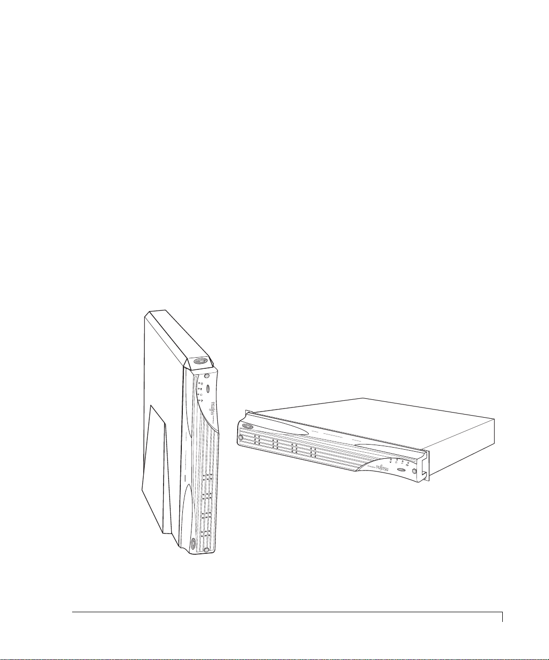
Tower Model
Rack-Mount Model
imageRAID® Series Storage System
R
E
S
E
T
A
L
A
R
M
1
Page 14
Chapter 1 - Getting Started
At a Glance
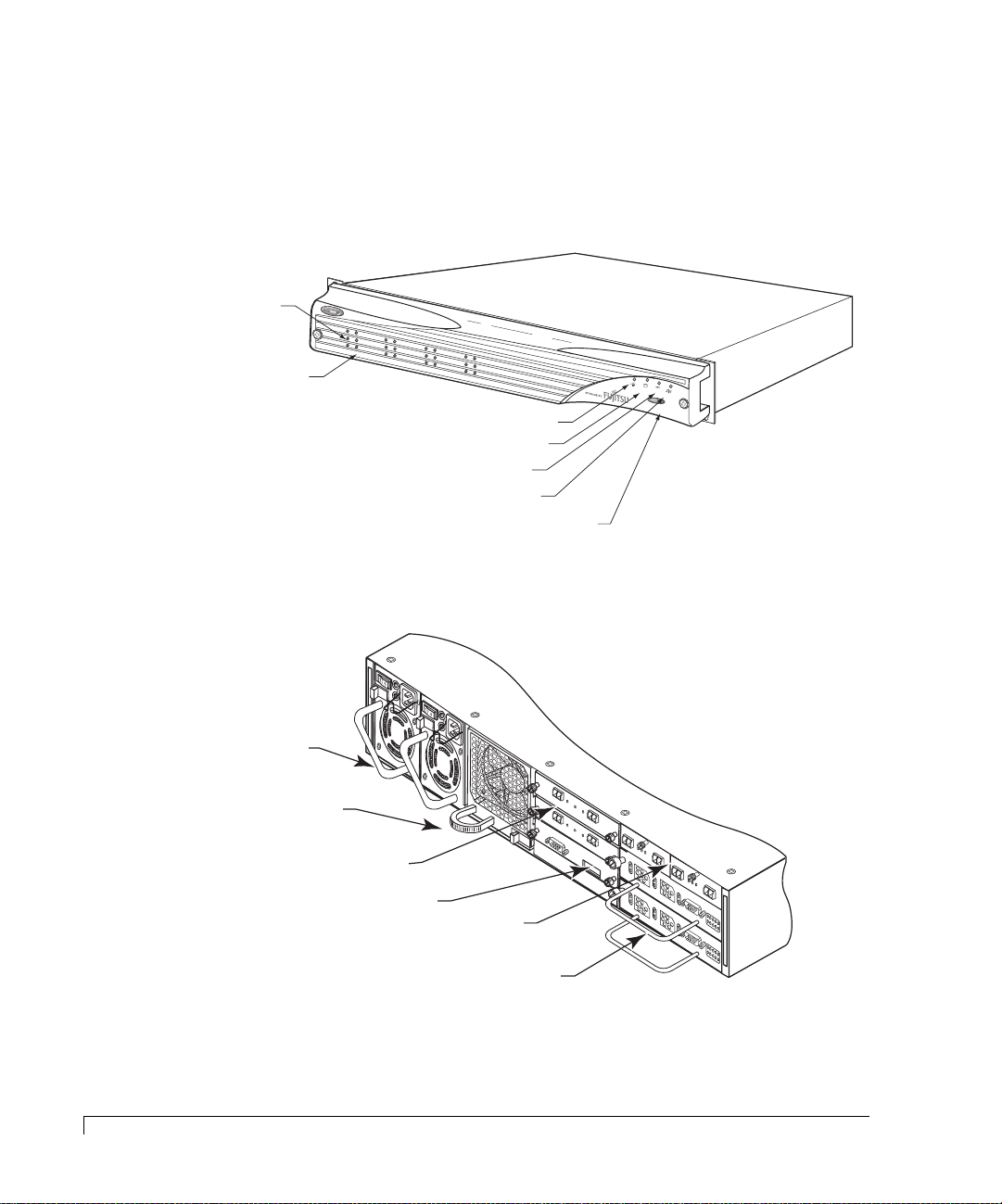
The following illustrations show the featured components of the imageRAID
Series Storage System. Familiarize yourself with its components prior to installing
and using the storage system.
Drive Status LEDs
(left column of LEDs)
Drive Activity LEDs
(right column of LEDs)
Power On LED
Channel Status LED
Power Supply Status LED
Fan Status LED
Alarm Reset Button
R
E
SE
T A
LAR
M
2
At a Glance
350-watt hot-pluggable
independent power supplies
Dual in-line 80-CFM hot
swappable cooling fans
Disk I/O Cards
SES Controller Card
Host I/O Cards
imageRAID Controllers
DISK I/O
D
1
T
x
T
x
T
x
D
I
D
S
D
K
1
T
I
x
/
O
T
x
R
S
-
2
T
3
x
2
D
S
E
S
A
A
A
D
D
D
0
1
Component Views
A
/W
P
R
/N
ev-1
08-9-96318001
Fibre D
FA
I
LU
FO
R
R
IN
E
H
D
S
A
TA
E
R
TE
DW
LL JU
CT
A
R
M
E
P
ER
S
1 &
2
JP
1
F
A
I
L
F
U
O
R
R
E
IN
H
D
S
A
E
T
R
T
A
E
D
L
C
W
L
T
J
A
U
R
M
E
JP
P
E
2
R
S
1
&
2
J
P
1
A
R
T
P
W
A
RT
O
S
R
E
N
K
S
R
U
C
M
E
O
B
V
N
E
IS
T
R
IO
R
0
O
N
8
L
-1
-9
L
E
-9
R
6
J
P
3
2
2
2
0
0
1
2
H
1
OK
2
2G
H
O
S
S
S
T
B
I/O
P
D
1K
P
R
2
D
1
L
2
M
R
Y
T
10/100
1K
10/100
SP
isk IO
LIT BU
A
D
D
LR
JU
S
C
M
M
PE
O
JP
D
R F
E
O
R
1G
O
A
D
PER
D
JU
ATIO
M
P
N
ER FO
R
A
/W
R
P
/N
e
v
J
0
-
F
P
1
8
ib
1
-
re
9
-9
D
6
is
3
S
1
k
P
IO
8
L
0
IT
0
A
L
1
D
B
R
D
C
U
JP
J
S
U
M
2
M
O
P
D
E
E
R
J
P
F
3
O
R
1
G
O
A
P
D
E
D
R
J
A
U
T
M
IO
P
N
E
R
F
O
R
J
P
2
OK
H
0
H
1
1K
O
K
O
H
K
2
H
0
G
O
O
VR
S
10/100
T
CUR
I/O
1K
PR
D
TNR
R
H
T
1
H
A
RS-232 DTE
0
A
O
VR
10/100
CUR
P
W
H
R
1
H
L
0
D
L
1
L
PR
D
TNR
R
H
T
1
H
A
RS-232 DTE
0
A
P
W
H
R
1
H
L
0
D
L
1
L
A/W REV-1
3
D
1
D
A
0
A
D
0
L
D
1
D
A
0
A
D
0
L
P/N 08-9-96319001
FIBRE HOST IO
PIN 8 - VCC
PIN 7 - VCC
PIN 6 - VCC
PIN 5 - C0CH0CH1_ENB
PIN 4 - C0C1_ENB
J
PIN 3 - HUB F
P
2
PIN 2 W
PIN 1 - 1G/2G
AHOO
SWITCH CONNECTIOONS
AILO
VER
A
/W
P
R
/N
E
F
0
V
IB
8
-1
-9
R
E
-9
H
6
3
O
1
S
9
T
0
0
IO
1
P
I
N
8
P
I
-
N
V
7
C
P
I
C
-
N
V
6
C
P
I
C
-
N
V
5
C
P
I
C
-
N
C
4
P
0
C
I
-
N
H
C
3
P
0
0
C
C
I
-
N
H
1
H
_
2
P
1
U
E
_
I
B
N
W
N
E
F
N
B
A
1
S
A
B
H
W
-
I
L
O
1
I
O
T
G
O
V
C
/
2
E
H
G
R
C
O
N
N
E
C
T
I
O
O
N
S
Page 15
Chapter 1 - Getting Started
Components
This section provides a description of each of the major components that
comprise the imageRAID Series Storage System.
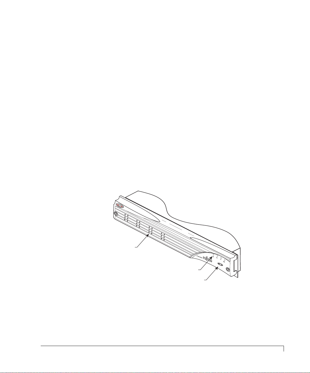
Front Bezel
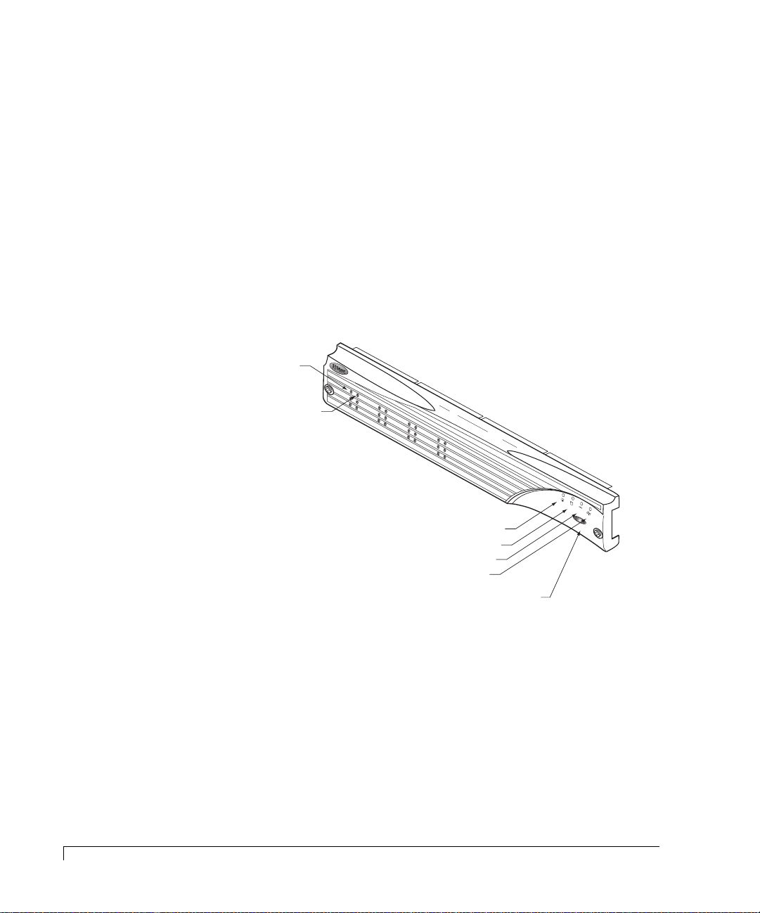
The front bezel houses the Status LEDs, Drive LEDs, and alarm reset button. When
removed, the user has access to the disk drives. The front bezel can be installed or
removed without interruption to system activities.
Embedded within the front bezel is the electronic package that provides the
communication with the SES controller. The SES controller manages the signals to
the front panel through a smart interface. Power is applied to the front bezel
through the interface edge connector, where a control circuit monitors the bezel
for proper connection. When the bezel is properly installed and power is applied
to the enclosure, the bezel is immediately energized.
Refer to “Control and Monitoring” on page 18 for details on the monitoring
functions.
Drive LEDs
R
e
s
e
t A
la
r
Status LEDs
Alarm Reset Button
m
Removable Front Bezel
To remove the bezel and gain access to the disk drives, use a Phillips screwdriver
to release both bezel fasteners, then grasp and remove the bezel. The fasteners
rotate one-quarter turn clockwise to lock and counter-clockwise to unlock.
Components
3
Page 16
Chapter 1 - Getting Started
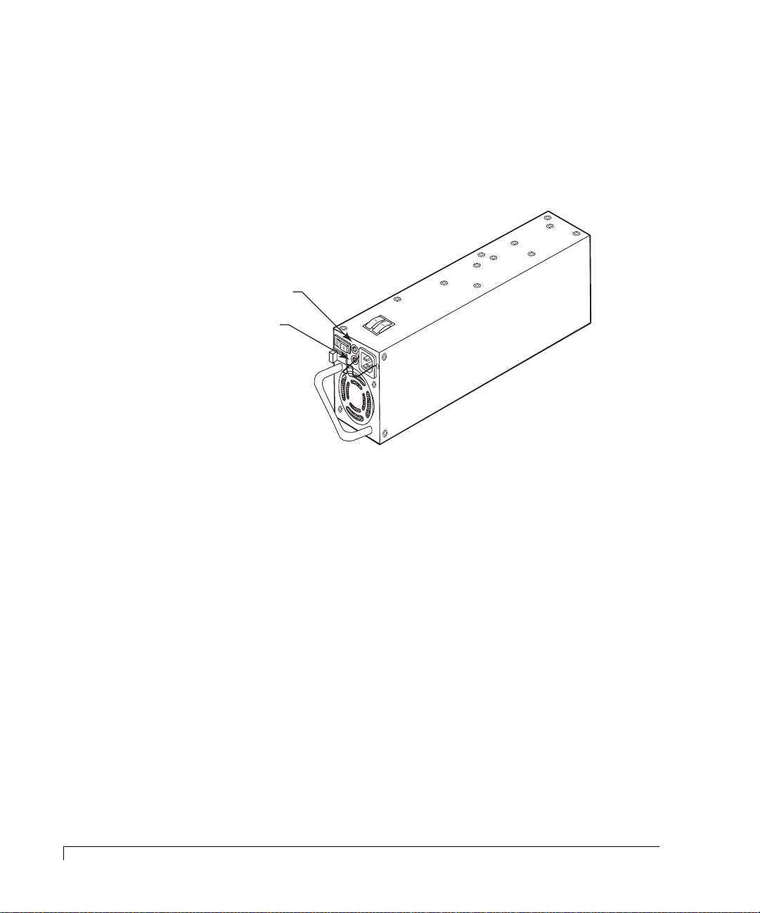
AC Power
The power system consists of two 350-watt hot-pluggable power supplies, each
with independent AC power cords and cooling fans. This power system provides
the enclosure with “N+1” redundant power. Each power supply has auto-switching
circuitry for use with either 100V or 240V AC systems.
Power On LED
(green)
Fault LED
(amber)
Power Supply
Power is applied to the enclosure by pressing each of the two power supply
On/Off switches to their “On” position. A Power On LED located on each power
supply will be illuminated indicating that AC power has been applied. The front
bezels’ Power On LED will also be illuminated indicating that power has been
applied.
Each power supply also incorporates an amber general Fault LED. If the power
supply is installed and power is not applied to the power supply or the power
supply cooling fan fails, the Fault LED will illuminate, along with an audible alarm.
The front bezels’ Power Supply Status LED will illuminate green when both
power supplies are on and operating normally. If only one power supply is
operational, the Power Supply Status LED will be illuminated amber.
Each power supply has an AC Power Cord Module. The module has a power
cord bale incorporated into the design to secure the power cord once it has been
properly inserted. The bale prevents inadvertent disconnects.
4
AC Power
Page 17
Chapter 1 - Getting Started
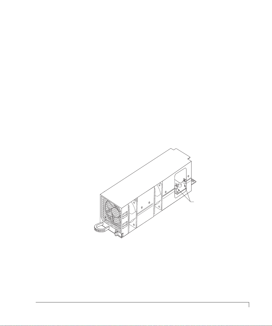
Cooling Fan Module
The cooling system consists of two high-performance (80-CFM) cooling fans
mounted in a single fan module which slides into a bay at the rear of the
enclosure. The design of the fan module provides for an easy-to-install user-
replaceable component in a live environment without interruption of service.
If any one fan should fail, cooling redundancy and efficiency are degraded. The
cooling fans and enclosure temperature are constantly monitored by the SES
processor for fault conditions. In the event of a fault condition the front panel Fan
Status LED will change from a green state to a solid amber state in the case of a fan
failure, or to a blinking amber green state in the case of an over-temperature
condition. In both cases an audible alarm sounds. The SES processor will also
provide notification data to monitoring software, such as StorView.
WARNING:
Do not operate the enclosure for extended periods of time (greater
than 5 minutes) with the cooling fan module removed.
Fan Speed Override Control
Jumpers JP1 (Fan 0)
and JP2 (Fan 1)
Cooling Fan Module
The enclosure has temperature sensors in three different areas, the drive bay, the
imageRAID Controllers, and the power supplies. There are several steps the storage
system performs to prevent component damage due to over temperature
conditions.
Cooling Fan Module
5
Page 18

Chapter 1 - Getting Started
If the drive bay area reaches a temperature of 50°C (122°F) an audible alarm will
sound, the front panel Fan Status LED will toggle amber green, and the monitoring
software will post a warning message. These notifications give the user a warning
that some condition is causing the enclosure temperature to exceed the preset
value, and an action is required by the user to determine the cause and take
corrective measures. It may be due to a blockage of air flow or a low fan speed.
If any controller reaches a temperature of 65°C (149°F) an audible alarm will
sound, the front panel Fan Status LED will alternate amber and green, and the
monitoring software will post a warning message. If the temperature on any
controller continues to rise and reaches 71°C (159°F), the controller will flush its
cache and shutdown. If it is the only controller (Simplex mode) or the only
remaining controller (surviving controller from a failed over operation) then the
controller will also spin down the disk drives at this temperature.
If any power supply reaches 85°C (185°F) the power supply will shut down.
The SES Controller card has a firmware-based VT-100 interface which provides an
option to manage fan speed. This option provides a whisper mode fan operation
for noise sensitive environments. When enabled (default), and based on a set of
conditions, the software will manage the cooling fans RPM speed to maintain the
enclosure temperature while minimizing noise levels. Refer to “Enclosure Fan
Speed Control” on page 122 for more details on using this option.
6
Cooling Fan Module
A manual override of the fan speed control is available for special circumstance
environments. Referring to the illustration on the preceding page, two jumpers are
provided on the fan module printed circuit board to override the software control
of the fan speeds. This hardware setting routes full power voltage to the fans for
maximum operational speed, which is greater than the maximum speed set by the
automatic software control. This configuration is normally used when fan speed
noises are not an issue, and the ambient operating temperature is at or above 30°C
(86°F), thus ensuring that maximum available cooling is being provided.
The jumpers JP1 and JP2 by default are offset, which enables the automatic fan
speed control. The jumper JP1 controls Fan 0 and JP2 controls Fan 1. Placing the
jumper on both pins for each jumper will override the automatic setting and
configure the fans to maximum power.
Page 19
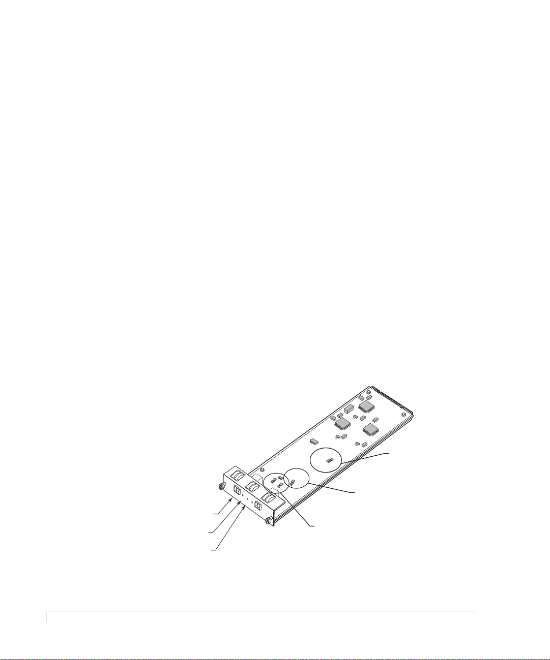
SES Controller Card
Chapter 1 - Getting Started
WARNING:
The SES Controller card is NOT HOT SWAPPABLE. You must POWER
DOWN the enclosure prior to removing or inserting this card.
The
SES Controller
card provides the built-in environmental and system status
monitoring. It also houses the switches for setting the drive spin up options. This
card is installed at the rear of the enclosure in the lowest slot below the two Disk
I/O cards.
The SES processors continuously monitor the enclosure for temperature status,
fan status, power supply status, and FC loop status. The processors are
responsible for reporting environmental and system status to the front bezel
LEDs/audible alarms, SES Monitoring software (VT-100), and external monitoring
software such as StorView.
J
P
2
A
R
T
P
W
A
R
O
S
T
R
E
N
S
K
C
U
R
M
O
E
B
V
N
E
I
T
S
R
R
I
O
08
O
N
L
-
-
L
9
E
1
-9
R
6
3
2
2
001
RS-232 Service Port
RS-232
SES
A
A
A
D
S
D
S
B
D
0
P
D
1
P
R
D
2
1
L
2
M
R
Y
T
SES Switches
SES Controller Card
At power up, the SES processors will read the switch settings and execute a
self-test. The cards’ firmware also contains software functions for enclosure
monitoring and management. This firmware is flash upgradeable using the SES
RS-232 Service port located on the card face plate. Refer to “Uploading SES
Controller Card Firmware” on page 119 for more details.
The SES protocol uses the drives installed in slots 1 and 7 to maintain its
communication link. You must install drives in both of these slots to ensure fault
tolerance for the SES communications link.
SES Controller Card
7
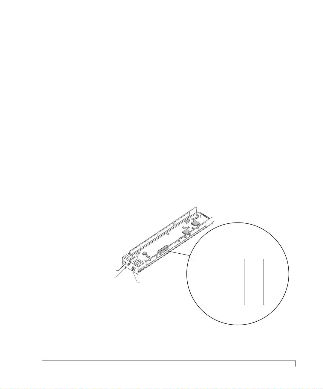
Page 20
Chapter 1 - Getting Started
Below is an illustration depicting the drive slot identification. Drive slot numbers
are not the drive device IDs. Drive slots appearing in gray are the SES
communication slots.
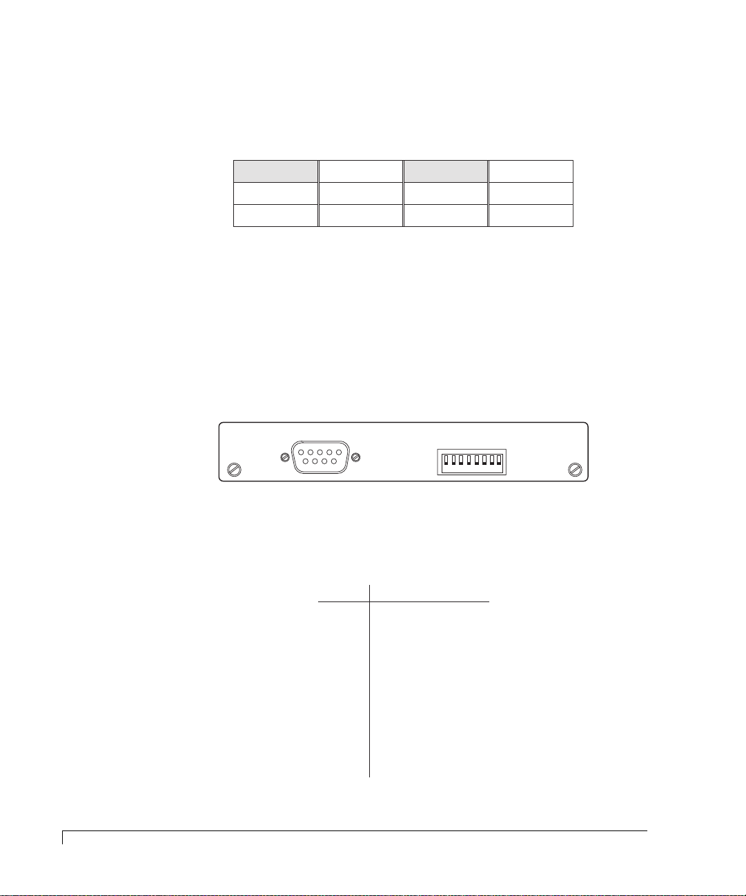
Drive Device ID Settings
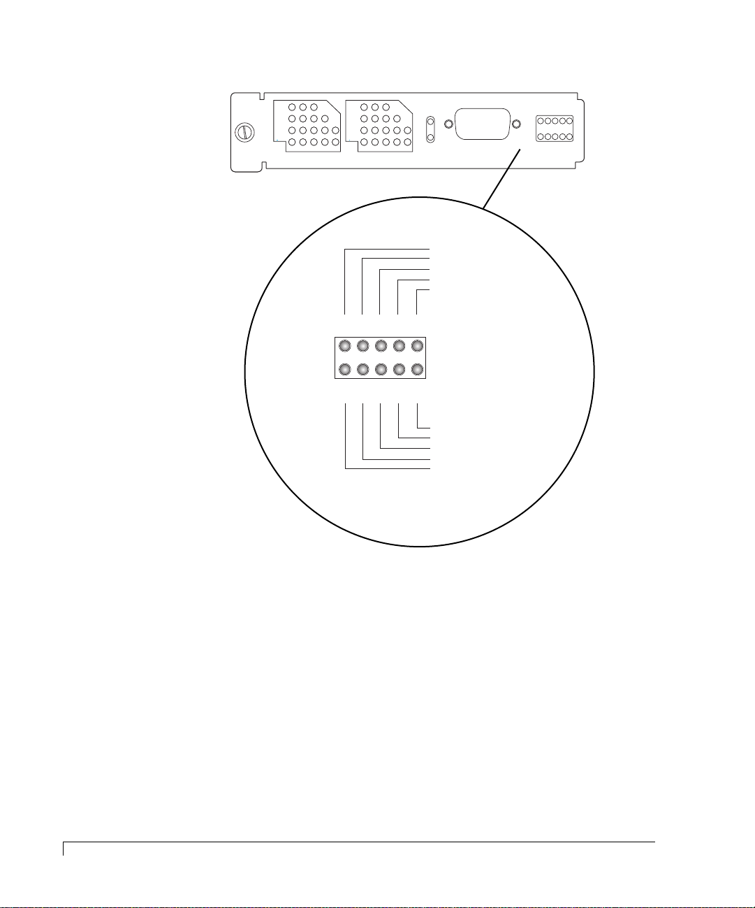
Located on the SES Controller card face plate are a set of switches. These
switches will configure the enclosure base Fibre address which configures the
disk drives in each drive slot with a device ID, as well as drive delay spin-up and
remote spin-up options. The default settings is all switches are set to their DOWN
position.
Viewed from the front of the enclosure
Slot 1 Slot 4 Slot 7 Slot 10
Slot 2 Slot 5 Slot 8 Slot 11
Slot 3 Slot 6 Slot 9 Slot 12
Drive Slot Location
S
A
A
A
S
B
D
RS-232
SES
D
0
12
D
1
P
D
P
D
L
1
2
2
R
Y
345678
R
M
T
Up position
Down position
8
Drive Device ID Settings
SES Controller Card Switches
The left three switches (AD0, AD1 and AD2) will configure drive slots with a
series of pre-determined device IDs. Refer to the table below:
A
A
D
Switch
Ranges
IDs 0-11
IDs 16-27
IDs 32-43
IDs 48-59
IDs 64-75
IDs 80-91
IDs 96-107
IDs 112-123
0
Down
Down Down
Down
Up Down
Down
Up Up
Down
Down
UpUp Up
Disk Device ID Switch Settings
A
D
D
1
2
DownUp
Down
UpDown
UpUp Down
UpUp
Page 21

Chapter 1 - Getting Started
For example, if the setting for switches 1 through 3 are “Down.” the device ID
addresses for the drive slots 1 - 12 would be 0 - 11 respectively.
NOTE:
If a hard address ID conflict occurs during Fibre Channel loop
initialization, the Fibre Channel protocol will dynamically set the drive
IDs. This could cause problems with some software products.
Switches 4, 5, and 6 are not used.
Spin-Up Settings
Switches 7 and 8 control the drive spin-up functions. The switches are directly
attached to all of the drive slot start signals. Switch 7 controls the “Start_1” signal
(Delay Spin-up) and switch 8 controls the “Start_2” signal (Remote Spin-up).
The table below describes the function of each switch.
“DL” Switch 7 “RM” Switch 8 Drive Spin-up Mode
Down (0)* Down (0)* Drive motor spins up at DC power on.
Down (0) Up (1) Drive motor spins up only on SCSI “start”
commands.
Up (1) Down (0) Drive motor spins up after a delay of 12
(may vary depending on drive type) seconds
times the numeric ID setting of the
associated drive.
Up (1) Up (1) Drive motor will not spin-up.
* Default setting for proper operation.
Spin-Up Settings
9
Page 22
Chapter 1 - Getting Started
Disk I/O Card
The Disk I/O card is provided for drive channel expansion. By connecting daisy
chained IRF-JBOD enclosures to the Disk I/O cards additional enclosures and
drives can be added to your system. This card’s design incorporates an active
hub, and provides automatic loop regeneration (LRC) and port bypass. The loop
regeneration function will “heal” the FC-AL (Fibre Channel-Arbitrated Loop)
when components become disconnected or faulty.
There are two Disk I/O cards installed at the rear of the enclosure adjacent to the
cooling fan bay. The upper Disk I/O card provides the connection to the “Loop
0” side of the disk drives, and the lower Disk I/O card provides the connection to
the “Loop 1” side of the disk drives.
Each Disk I/O card supports Small Form-Factor Pluggable (SFP) cages to accept
either optical or copper transceivers. They are designed to support NCITS T11
Fibre Channel compliant devices at speeds of 1.0625 Gb per sec or 2.125 Gb per
second. The speed is set through a hardware jumper (JP4) located on the Disk
I/O card. Set the jumper on one pin only or offset for 2Gb mode. If you need to
configure the system for 1Gb mode, position the jumper to both pins. An LED on
the card’s faceplate will illuminate to indicate the 2 Gb mode.
10
Disk I/O Card
FC-AL Loop Port
Loop Status LED
2 Gb/1 Gb Mode LED
P1
DISK I/O
OK
2G
OK
P2
A/W Rev-1
P/N 08-9-96318001
FAILURE DETECT
FOR HARDWARE
INSTALL JUMPERS 1 & 2
1G OPERATION
JP2
ADD JUMPER FOR
JP4
JP1
Disk I/O Card
SPLIT BUS MODE
ADD JUMPER FOR
Fibre Disk IO LRC
JP3
Jumpers JP1 and JP2
must be installed on
both pins .
Jumper JP3 must be offset
or installed on one pin only.
This enables Single Bus mode.
Jumper JP4 must be set
to one pin only for 2Gb mode.
Position it on both pins for
1Gb mode.
Page 23
Chapter 1 - Getting Started
The jumper, (JP3), must be set to one pin only or offset. This configures the bus
to single bus mode.
The jumpers JP1 and JP2 must be installed on both pins. They provide hardware
failure detect signals.
NOTE: The Disk I/O cards are universal and can be interchanged.
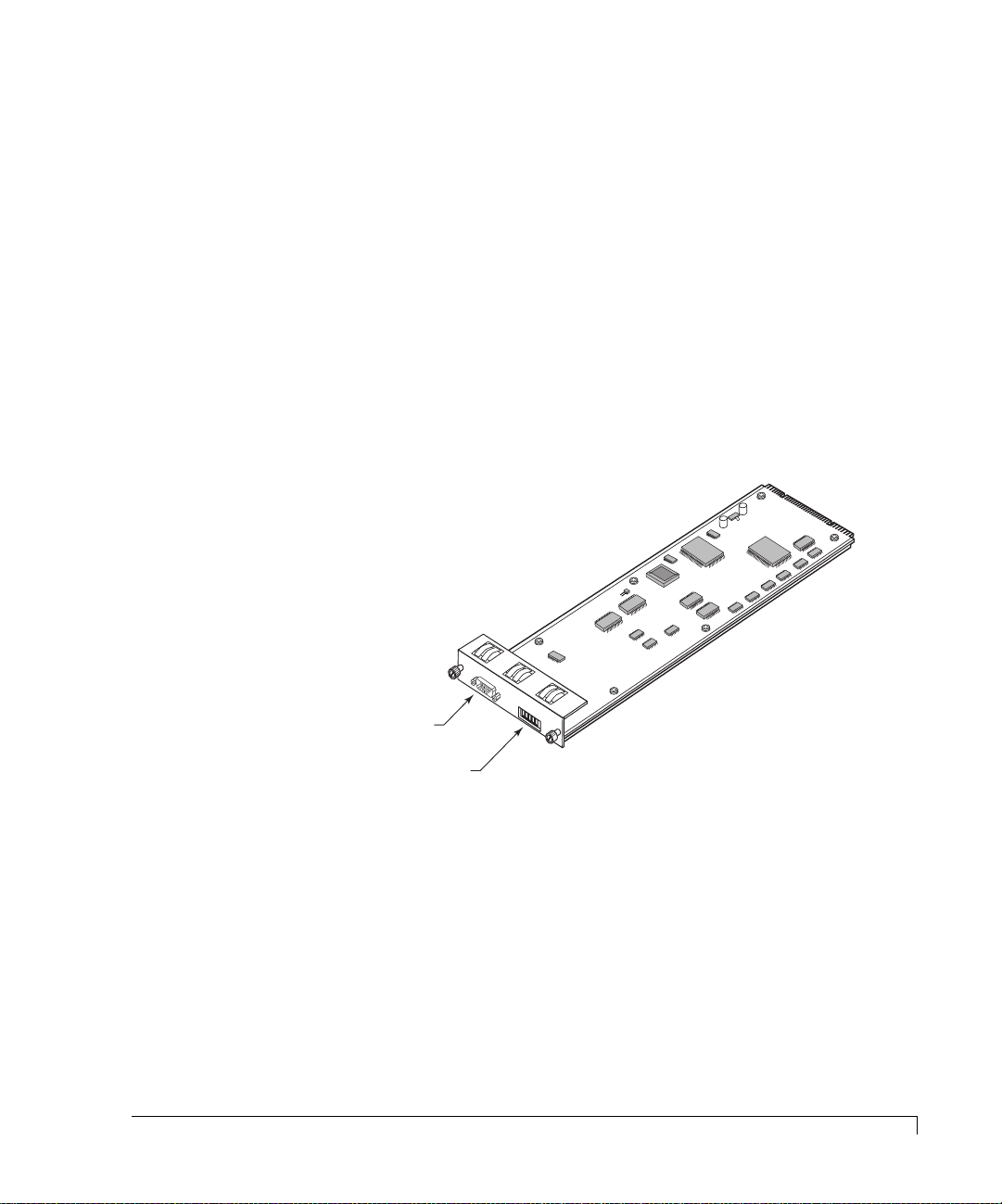
Host I/O Card
The Host I/O card provides the fibre connectivity from the host computer(s) to
the Fibre Channel controller ports. This hot swappable card is designed to
support NCITS T11 Fibre Channel compliant devices at speeds of 1.0625 Gb per
sec or 2.125 Gb per sec. Each card has two SFP cages that house optical or
copper SFP transceivers. They are labeled “H0” and “H1.”
The Host I/O cards are installed at the rear of the enclosure, above the controller
slots. The right Host I/O card provides connectivity to controller’s port 0 (C0P0 and
C1P0) of both controllers, and the left card provides connectivity to controller’s
port 1 (C0P1 and C1P1) of both controllers.
LEDs on the card’s face plate will illuminate to indicate 2 Gb speed mode, host
link status, and activity.
FC Host Ports
Link Status LED
H0
O
K
H1
2
H
G
O
O
S
K
T
I/O
A/W
P/N 08-9-96319003
R
EV-1
E H
OST IO
S
W
I
T
H
C
O
H
S
P
T
C
O
T
S
S
R
P
I
T
L
E
H
I
E
M
O
U
D
N
O
B
D
H
F
E
O
A
O
I
N
S
L
O
/
T
C
O
V
T
H
1
F
E
L
G
0
F
R
R
H
/
D
2
D
0
1
G
U
I
P
L
S
A
0
I
/
L
N
E
P
D
K
N
A
1
I
S
C
A
/
T
E
D
I
N
V
I
S
E
A
/
E
D
N
I
S
A
/
E
D
N
I
S
A
G
/
E
N
N
D
A
G
/
V
N
C
D
C
/
V
C
C
2 Gb/1 Gb Mode LED
FIBR
Host I/O Card
Switch Name
1
HOST SPEED 1G/2G
2
CTRL MODE DIS/ENA
3
HUB FAILOVER DIS/ENA
4
HOST H0H1 LINK DIS/ENA
5
CTRL0 P0P1 LINK DIS/ENA
6
DUAL ACTIVE DIS/ENA
7
GND/VCC
8
GND/VCC
Switch Settings
2 Gb
imageRAID
Enabled
Enabled
Not Used
Enabled
Not Used
Not Used
Function
UP (ON) DOWN (OFF)
1 Gb
Not Used
Disabled
Disabled
Not Used
Disabled
Not Used
Not Used
Host I/O Card
11
Page 24

Chapter 1 - Getting Started
The following table defines the function of each switch:
Switch Name Function
1 HOST SPEED Sets the FC Loop speed to 1 Gb or 2 Gb. An LED on the
card will illuminate to indicate 2 Gb mode. The “up”
position sets 2 Gb mode and the “down” position will set
the loop to 1 Gb mode.
2 CTRL MODE Sets the enclosure for a specific controller model. This
switch must be set to the “up” position for the
“imageRAID” Controller. The “down” position is not
applicable.
3 HUB FAILOVER This switch is not used.
4 HOST H0H1 LINK This switch when enabled, “up” position, provides the
link between the Host I/O card H0 and H1 ports. This
switch should be set to the “down” position when Switch
6 is enabled (‘up’ position).
5 CTRL0 P0P1 LINK This switch is not used.
6 DUAL ACTIVE This switch is enabled (up position) when dual
controllers are installed. It is used to enable automatic
internal hub failover during a controller failure.
7 GND/VCC This switch is not used.
8 GND/VCC This switch is not used.
12
SFP Transceiver
Each card contains Port Bypass Circuits (PBC) that allows for hot swapping,
improved signal quality and valid FC signal detection. An onboard Clock
Recovery Units (CRU) is provided to improve the signal quality, determine
whether the input is a valid FC signal, and amplification and jitter removal for
optimum quality signals.
Cabling diagrams are provided in the Installation chapter for each supported
topology. To ensure proper connectivity, failover and failback operations, and
LUN presentation, follow the cabling diagram for your selected topology.
SFP Transceiver
The Host I/O and Disk I/O cards incorporate SFP cages which support optical
hot-swappable Small Form-Factor Pluggable (SFP) transceivers.
The optical SFP transceiver is Class 1 Laser safety compliant and conforms to
Class 1 eye safety standards.
CAUTION:
Do not look into the laser light beam for any extended period of time.
Page 25
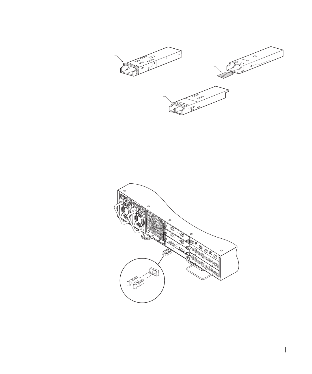
Chapter 1 - Getting Started
Ejector Release Lever
Ejector Release Tab
Ejector Release Lever
SFP Optical Transceiver Models
NOTE: Refer to the Installation chapter for transceiver installation procedures.
Dust covers are provided to protect the transceivers’ optics. It is highly recommend
that the dust covers be installed when a connector is not in place.
A
/W
P
R
/N
e
08
Fibre D
v-1
-9-9
F
A
I
L
F
U
O
R
R
E
H
D
A
T
E
R
A
TE
D
L
L JU
W
C
A
T
R
M
E
P
E
R
S
1
&
2
JP
1
FA
I
LU
FO
R
R HA
E
IN
D
S
E
TA
R
TE
DW
LL JU
C
T
A
R
M
E
JP
P
E
2
R
S
1 &
D
2
I
S
D
K
1
JP1
T
I
x
T
x
DISK I/O
D1
T
x
T
x
RS-232
S
E
A
/
R
O
T
P
W
A
R
O
T
R
N
K
S
R
U
C
M
E
O
B
V
N
E
IS
T
T
R
IO
RO
x
0
N
8
L
-1
-9
LE
-9
R
6
JP
32
2
2
0
0
D
1
2
H
1
T
x
O
K
D2
S
A
A
H
A
OST
D
S
D
S
D
B
0
P
D
1
1
P
K
R
2
D
1
L
2
M
R
Y
T
1
0
/
1
0
0
1
K
1
0
/1
0
0
S
P
6318
isk IO
L
A
IT
D
B
0
D
IN
L
01
U
JU
R
S
S
C
M
M
P
O
JP
E
D
R
E
F
O
R
1
G
O
A
D
P
E
D
R
JU
A
TIO
M
P
N
E
R
F
O
R
A
/W
R
P
/N
ev-1
J
08-9-9
Fibre
P
1
D
6318001
isk IO
S
P
LIT
AD
LR
BU
D
C
JP
JU
S
M
2
M
O
P
D
E
E
R
F
O
R
1G
O
A
P
D
E
D
R
JU
ATIO
M
PE
N
R
F
O
R
S
E
JP
2
O
H
K
2
0
G
I/O
H
1
1
K
O
K
O
K
2
H
G
O
O
S
V
R
T
1
0
C
/
I/O
1
U
0
0
R
1
K
P
D
R
T
N
R
R
T
RS-232 DTE
O
V
R
1
0
C
/
1
U
0
0
R
P
W
R
P
D
R
T
N
R
R
T
RS-232 DTE
P
W
R
A
3
/W
P
R
/N
E
F
0
V
IB
8
-1
-
R
9
E
-
9
H
6
3
O
1
S
9
T
0
IO
0
1
P
I
N
8
P
I
-
N
V
7
P
C
JP
I
C
-
N
V
3
6
P
C
I
C
-
N
V
5
P
C
I
C
-
N
C
J
4
P
0
P
I
C
-
N
C
2
H
3
P
0
0
I
C
C
-
N
H
1
H
2
P
_
U
1
E
I
_
B
N
W
N
E
F
1
A
S
B
N
A
H
W
B
-
I
L
O
1
I
T
O
G
O
C
V
/
2
H
E
G
R
C
O
N
N
E
C
T
I
O
O
N
S
P
I
N
8
P
I
-
N
V
7
C
I
C
-
N
V
6
C
C
-
V
C
C
-
C
0
C
H
0
C
H
1
_
1
E
_
N
E
N
B
B
I
L
O
V
E
R
H
0
H
1
H
A
0
D
A
1
D
A
0
A
H
1
H
L
0
D
L
1
D
L
0
L
H
1
H
A
0
D
A
1
D
A
0
A
H
1
H
L
0
D
L
1
D
L
0
L
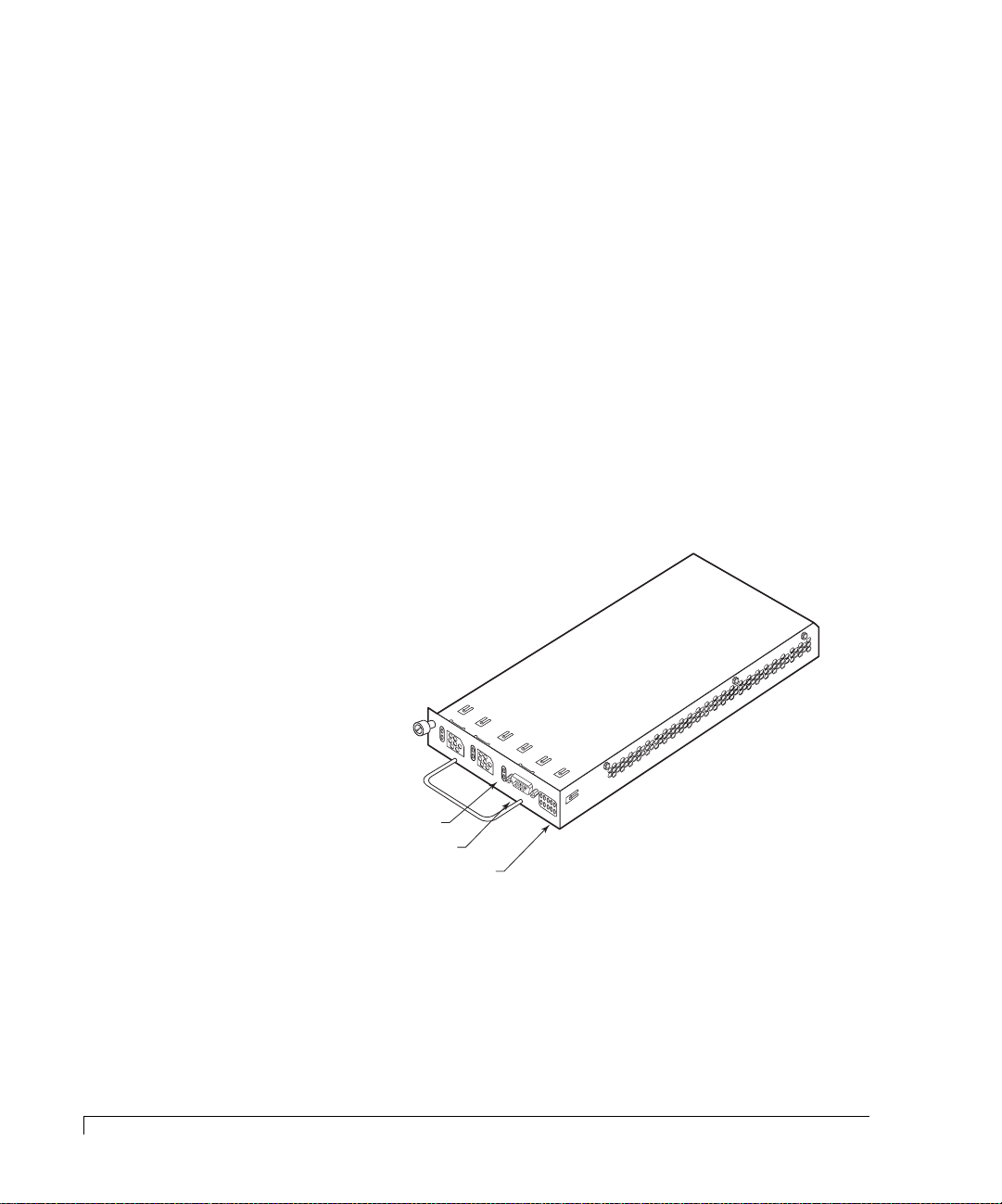
Install the Dust Covers
when the optical transceiver
port is not in use.
Installing and Removing Optical Transceiver Dust Covers
E
V
-1
6
3
1
90
01
P
P
I
N
5
P
I
N
4
P
I
-
N
C
3
P
0
C
I
-
N
H
2
P
U
I
B
N
W
F
A
1
S
A
H
W
-
O
1
I
T
G
O
C
/
2
H
G
C
O
N
N
E
C
T
I
O
O
N
S
A
/W
P
R
/N
FIB
0
8
-9
R
E
-9
H
O
S
T
IO
SFP Transceiver
13
Page 26
Chapter 1 - Getting Started
RAID Controllers
The imageRAID Series Storage System is designed to house one or two hot
pluggable imageRAID Controllers. They are next generation dual port
high-performance 2 Gb/second Fibre Channel-to-Fibre Channel RAID controllers
supporting RAID levels 0, 1, 5, 10, and 50.
There are two models of the
a FC-FC RAID Controller with a single RISC processor. The
imageRAID
Controller. The base
imageRAID
imageRAID
XP model is
model is
the base controller plus a co-processor.
The controllers are
designed for “I/O Intensive” and “Bandwidth Intensive”
applications, providing simplex (stand-alone) and duplex (active-active)
configurations designed for existing and future Fibre Channel topologies.
simplex operations, the controller operates autonomously. In
duplex
In
configurations, the two controllers operate as a pair. In the event one controller
fails, fault tolerance is maintained via hardware failover allowing either controller to
take over the operations of the other controller.
1K
1
10
K
/10
0
Over Current & Partner Controller Status
RS-232 Service Port
Controller Status LEDs
O
V
R
10
C
/100
U
R
P
DRT
R
T
N
R
H1A
H0A
R
D1A
S-232
D0A
DTE
PWR
H1L
H0L
D1L
D0L
14
Fibre Channel-Fibre Channel imageRAID Controller
Each controller has two Fibre Channel ports and two Fibre Channel disk ports for
a “2x2” configuration (dual host-dual drive). In duplex configurations, it can
process up to 80,000 I/O’s per second (IOPS). The active-active pair of RAID
controllers can feed data to SAN nodes at a sustained rate of 320 MB/sec, and
process RAID 5 write operations at 220 MB/sec.
RAID Controllers
Page 27

Chapter 1 - Getting Started
The core processor of the controller is based on an Intel XScale™ RISC processor
running at 600 MHz. The processor has integrated instructions and data caches
that allow for the most frequent instructions to be executed without having to
access external memory. Coupled with the micro kernel, it processes commands
and I/O’s at extremely high rates.
The processor’s companion chip implements dual independent 64-bit 66MHz PCI
busses. Devices on these busses have independent access to the shared 512 MB
of SDRAM. Also, an integrated XOR accelerator is included for RAID 5 or 50
parity generation.
The imageRAID Controller disk drive interface uses QLogic ISP 2312 dual Fibre
Channel controllers which takes full advantage of the dual fibre loops on each
disk drive. The controller’s host interface also uses QLogic ISP 2312 dual Fibre
Channel controllers which provides two independent ports for host connectivity.
Each port can operate at either 1 Gb/sec or 2 Gb/sec, and the controller will
automatically detect the correct rate. The ports are sometimes referred to as “Host
Loops.”
Located on the controller face plate are Activity, Link and Status LEDs. Refer to
the table below and the illustration on the following page for descriptions for
each LED.
NOTE: The “TXRX-LNK” and “1K-10/100” LEDs are provisions for future options.
RAID Controller Face Plate LEDs
PWR
OVR CUR
PRTNR
TXRX - LNK
1K - 10/100
Indicates power is applied.
Indicates controller over current condition exceeds +5V.
If on, it will indicate that the partner controller has failed.
Option for future enhancement.
Option for future enhancement.
RAID Controllers
15
Page 28
Chapter 1 - Getting Started
Amber LEDs
D0A
D1A
H0A
H1A
O
VR
C
UR
RS-232 DTE
P
RTNR
DRT = Cache Dirty
H1A = Host Loop 1 Activity
H0A = Host Loop 0 Activity
D1A = Drive Loop 1 Activity
D0A = Drive Loop 0 Activity
On = Activity Sensed
DRT
H1A
H0A
D1A
D0A
Off = No Activity
DRT
PWR
H1L
H0L
D1L
D0L
Green LEDs
PWR
H1L
H0L
D1L
D0L
D0L = Drive Loop 0 Link Status
D1L = Drive Loop 1 Link Status
H0L = Host Loop 0 Link Status
H1L = Host Loop 1 Link Status
PWR = Power Applied
On = Link Valid
Off = Link Invalid
imageRAID Controller Face Plate LEDs and Descriptions
Battery Backup Unit
The main board of the imageRAID Controller includes battery control circuitry for
a single cell Lithium Ion battery along with a battery pack mating connector. The
main purpose of battery backup is to maintain the cache memory during brief
power interruptions, but is capable of maintaining the memory content for
several hours, depending on the type and size of the memory.
16
Battery Backup Unit
Page 29

Chapter 1 - Getting Started
The battery control circuitry has constant current, constant voltage (CCCV) charger.
The battery charger provides a maximum 250mA charge current. When the charge
current falls below 16mA, the charger determines that the end of charge has been
reached, generates an end of charge indication and shuts itself off. If the battery
voltage drops below 3.0V, a complete battery discharge is indicated.
The battery control circuitry includes a battery safety circuit. The safety circuit
protects the battery by limiting the over-voltage to 4.3V, the maximum discharge
current to 3A for catastrophic events, and the minimum battery voltage to 2.35V. If
any of these conditions exist, the safety circuit disconnects the battery. These
conditions will only exist if there is a hardware fault present, and would never be
seen under normal operating conditions. In addition, the battery pack utilized, part
number 44-9-95611001, includes a resettable polyfuse that trips when the current
exceeds 700mA at room temperature. This protects the 1 amp rated connector
when for example a partial short exists caused by aa component failure.
Lithium Ion batteries have no requirement for conditioning, even after partial
discharges. The current battery pack utilizes a Renata ICP883448A-SC cell, with a
nominal capacity of 1150mAh. For a completely discharged battery, the charge time
is approximately 5 hours. Under lab conditions, current draw was measured for
different configurations of memory. The table below shows the results of those
tests, and the expected backup time is indicated for the specified memory
configuration. The table shows the absolute maximum backup time calculated from
the current draw measurements. The “Expected Safe Backup Time” is the absolute
maximum de-rated by 50% to account for different operating temperatures and
capacity reduction due to battery charge/discharge cycles. This is the time that
should be used when developing a system level power backup plan.
BBU Battery Hold-Up Times
Configuration
Main board
only w/512 MB
Main board
w/512 MB and
Coprocessor
w/512 MB
Memory Vendor and
Part Number
Kingston
KVR100X72C2/512
Kingston
KVR100X72C2/512
Measured
Current Draw
27.9mA 41.2 hours 20.6 hours
48.3mA 23.8 hours 11.9 hours
Absolute Maximum
Backup Time
Expected Safe
Backup Time
Battery Backup Unit
17
Page 30
Chapter 1 - Getting Started
Control and Monitoring
An integral part of the imageRAID Series Storage System is its control and monitor
capabilities.
The SES processors provide monitoring data for the enclosure environmental
conditions such as enclosure temperature, cooling fans, power supplies, and FC
Loop status. This data is reported to the monitoring system to provide LED and
audible alarm notifications. This monitored information is also communicated to
external monitoring software.
Refer to “VT-100 Interface Enclosure Monitoring” on page 116 for complete
details.
Drive Status LEDs
(left column of LEDs)
Drive Activity LEDs
(right column of LEDs)
18
Control and Monitoring
R
e
se
t A
la
Power On LED
Channel Status LED
Power Supply Status LED
Fan Status LED
Alarm Reset Button
rm
Front Bezel LEDs and Reset Button Identification
The imageRAID Controllers provide monitoring data for its environmental
condition and logical arrays. They communicate that data to the front bezel LEDs,
third-party configuration and monitoring software such as StorView, and the
VT-100 firmware-based interface for management and monitoring. (Refer to the
software user’s guide for configuration, management, and monitoring of the
controllers and logical arrays.)
Page 31

Chapter 1 - Getting Started
The
imageRAID
Display” which provides LED readout of the fan control, Host I/O and Disk I/O
speed modes, Disk I/O and Host I/O card presence and controller presence. Refer
to “One-Touch Annunciation Configuration Display” on page 115 for more details.
Series incorporates a “One-Touch Annunciation Configuration
Status Indicator LEDs
The Status Indicator LEDs comprise the Power-On LED, Channel Status LED,
Power Supply Status LED, and Fan Status LED. These series of LEDs are grouped
on the right side of the front bezel directly above the Alarm Reset button. The
following is a description of each of these LEDs.
Power-On LED
The Power-On LED signifies that the enclosure is powered on and will be
illuminated green when power has been applied.
Channel Status LED
The Channel Status LED will illuminate green to indicate a valid status of the FC
loop or a logical array. Should an error occur, the LED will change to amber.
Power Supply Status
The Power Supply Status LED indicates the condition of the power supplies. The
LED will illuminate steady green when both power supplies are functioning
normally and will change to amber if one of the power supply should fail or is
turned off.
Fan Status
The Fan Status LED indicates the condition of the cooling fans. The LED will
illuminate green when both fans are functioning normally and will change to
amber if any of the fans fail.
Status Indicator LEDs
19
Page 32

Chapter 1 - Getting Started
Drive LEDs
The Drive LEDs are located on the left side of the front bezel in between the
ventilation ribs, and comprise the Drive Status LEDs and Drive Activity LEDs. The
Drive LEDs are grouped in pairs and are in the general location of the disk drive
slot. There are 12 Drive Status and 12 Drive Activity LEDs, one group for each
disk drive.
Refer to “Drive LEDs” on page 110 for detailed information.
Audible Alarm
An audible alarm will sound when any of the enclosure’s component status
changes to an abnormal state. To silence the alarm, press the Alarm Reset button
located on the front bezel. The corresponding alarm’s LED will remain
illuminated until the condition returns to a normal state.
20
Drive LEDs
Page 33

Chapter 2
Topologies and Operating Modes
This chapter provides an overview of the supported operating modes and
topologies. This information should provide you with an understanding to make
the best choices for the optimum configuration that compliments your storage
system solution.
Essentially there are two operating modes available: Simplex and Duplex. The
IRF-1Sxx-xx or IRF-1Dxx-xx models with their single RAID controller support the
simplex operating mode, and the IRF-2Sxx-xx or IRF-2Dxx-xx models with their
dual RAID controllers support the duplex operating mode.
Operating Mode Overview
These operating modes allow you to configure the enclosure’s drives and RAID
controller(s) to support a variety of host environments topologies.
■ Simplex – In this operating mode, the enclosure is configured as a RAID
storage system with its single RAID controller operating in a stand-alone
configuration. This operating mode supports dual port topologies.
■ Duplex – In this operating mode, the enclosure is configured as a RAID
storage system with dual RAID controllers operating in an active-active or
redundant fault-tolerant configuration. This operating mode supports
Multiple Port Mirrored topologies.
21
Page 34

Chapter 2 - Topologies and Operating Modes
Simplex Mode
The simplex operating mode uses a single RAID controller solution that provides
a limited level of redundancy. With its dual port topology, the controller also
provides dual active ports that increases the bandwidth capabilities. Essentially,
there are four supported topologies for this operating mode:
■ “Dual Port Single Host Connection” on page 22
■ “Dual Port Single Host Dual Connection” on page 23
■ “Dual Port Multi-Host Single Connection” on page 24
■ “Dual Port Multi-Host Dual Connection” on page 25
Dual Port Single Host Connection
This topology provides an entry-level RAID storage solution for single ported HBA
host system. It offers the following advantages:
deploy
multiple points of failure (host server, host HBA, controller, and data cable), and it
has limited bandwidth capabilities due to its single Fibre loop (200 MB/sec).
and is a simple direct attached solution. It has several disadvantages:
an initially lower cost system to
22
Simplex Mode
Right Host I/O Card
Simplex Mode Logical View - Dual Port Single Host Connection
Host/Server (Node A)
FC HBA 1
H1
SW 4
H0
Port 0 (P0)
Active
Controller 0 (C0)
Port 1 (P1)
Active
H0H1
SW 4
Left Host I/O Card
Page 35

Chapter 2 - Topologies and Operating Modes
In this topology the Host I/O card switches 1, 2, and 4 are set to the “Up”
position.
Switch 1 sets the bus speed mode on the Host I/O card to 2 GB/sec.
Switch 2 configures the enclosure for the imageRAID Controller.
Switch 4 provides the link between the Host I/O card “H0” and “H1” ports to
the same Fibre loop.
Dual Port Single Host Dual Connection
This topology provides an entry-level RAID storage solution for dual ported host
systems with multiple paths to the storage. It offers the following advantages: an
initially lower cost system to deploy, multiple paths from host which can
maximize controller bandwidth, and it provides multiple paths for optional
upstream failover. It has several disadvantages: the RAID Controller is a single
point of failure, it requires two single ported HBAs or a dual ported HBA, and if
upstream path failover is implemented then additional software is required.
Host/Server (Node A)
FC HBA 1
Right Host I/O Card
H1
SW 4
FC HBA 2
H0
Port 0 (P0)
Active
Port 1 (P1)
Controller 0 (C0)
Active
SW 4
H0H1
Left Host I/O Card
Simplex Mode Logical View - Dual Port Single Host Dual Connection
In this topology the Host I/O card switches 1, 2, and 4 are set to the “Up”
position.
Switch 1 sets the bus speed mode on the Host I/O card to 2 GB/sec.
Dual Port Single Host Dual Connection
23
Page 36

Chapter 2 - Topologies and Operating Modes
Switch 2 configures the enclosure for the imageRAID Controller.
Switch 4 provides the link between the Host I/O card “H0” and “H1” ports to
the same Fibre loop.
Dual Port Multi-Host Single Connection
This topology provides a base shared RAID storage solution for up to four host
systems. It offers the following advantage: clustered storage between multiple
host system (no requirement for external hubs or switches). It has a few
disadvantages: the controller and the single fibre loop are single points of failure,
for clustering operations third-party clustering software is required and it also has
limited bandwidth performance due to a singe Fibre loop (200 MB/sec).
Host/Server (Node A) Host/Server (Node B)
FC HBA 1
Right Host I/O Card
H1
SW 4
H0
Port 0 (P0)
Active
Controller 0 (C0)
Port 1 (P1)
Active
H0H1
SW 4
FC HBA 1
Left Host I/O Card
Simplex Operating Mode Logical View - Dual Port Multi-Host Single Connection
In this topology the Host I/O card switches 1, 2, and 4 are set to the “Up”
position.
Switch 1 sets the bus speed mode on the Host I/O card to 2 GB/sec.
Switch 2 configures the enclosure for the imageRAID Controller.
Switch 4 provides the link between the Host I/O card “H0” and “H1” ports to
the same Fibre loop.
24
Dual Port Multi-Host Single Connection
Page 37

Chapter 2 - Topologies and Operating Modes
Dual Port Multi-Host Dual Connection
This topology provides a base shared RAID storage solution for up to four host
systems. It offers the following advantages: clustered storage between multiple
host system (no requirement for external hubs or switches). It has a few
disadvantages: the controller and the single fibre loop are single points of failure,
for clustering operations third-party clustering software is required and it also has
limited bandwidth performance due to a singe Fibre loop (200 MB/sec).
Host/Server (Node A) Host/Server (Node B)
FC HBA 1
Right Host I/O Card
H1
FC HBA 2 FC HBA 1 FC HBA 2
H0
SW 4
Port 0 (P0)
Active
Controller 0 (C0)
Port 1 (P1)
Active
SW 4
H0H1
Left Host I/O Card
Simplex Operating Mode Logical View - Dual Port Multi-Host Dual Connection
In this topology the Host I/O card switches 1, 2, and 4 are set to the “Up”
position.
Switch 1 sets the bus speed mode on the Host I/O card to 2 GB/sec.
Switch 2 configures the enclosure for the imageRAID Controller.
Switch 4 provides the link between the Host I/O card “H0” and “H1” ports to
the same Fibre loop.
Dual Port Multi-Host Dual Connection
25
Page 38

Chapter 2 - Topologies and Operating Modes
Duplex Mode
The duplex operating mode is a dual RAID controller solution providing a
redundant controller or an active-active RAID storage solution. Beginning with a
minimum level redundancy solution it can be configured to provide the most
robust redundant RAID storage solution. This operating mode supports the
Multiple Port Mirrored topology.
In a Multi-Port topology, all ports are active and provide transparent hardware
failover and failback operations. It provides for higher host bandwidth
capabilities with each port connected to an individual fibre loop.
During controller failure, internal HUB circuitry on the Host I/O cards
automatically detect a failure and connects the incoming Fibre loops together so
that the surviving controller immediately starts processing host commands.
There are essentially five supported topologies available for the Duplex mode:
■ “Multi-Port Mirrored Single Host-Single Connection” on page 27.
26
■ “Multi-Port Mirrored Single Host-Dual Connection” on page 28.
■ “Multi-Port Mirrored Dual Host System-Quad Connection” on page 31.
■ “Multi-Port Mirrored SAN Attach Single Switch Connection” on page 32.
■ “Multi-Port Mirrored SAN Attach Dual Switch Connection” on page 33.
NOTE: Some Operating Systems, such as HP-UX, when connected to a fabric
require that you set the Controller Parameter option “Host Different
Node Name” to enabled. This will cause the controller to present a
different Configuration WWN for each controller port. Otherwise if the
same WWN is reported on both ports, one port would be blocked by the
OS. Refer to the VT-100 or StorView Software Guide for specific
information on this option.
Duplex Mode
Page 39

Chapter 2 - Topologies and Operating Modes
Multi-Port Mirrored Single Host-Single Connection
This topology provides an redundant RAID storage solution for single host systems
with one fibre port where a fault-tolerant disk subsystem storage is required. It has
the following advantages: initial lower costs, redundant RAID controllers, and
transparent failover and failback operations. It has several disadvantages:
performance limited bandwidth capabilities due to the single Fibre loop, and the
host system, host HBA and the single fibre loop are single points of failure.
Host/Server (Node A)
FC HBA 1
Right Host I/O Card
Port 0 (P0)
H1
Active
Controller 0 (C0) Controller 1 (C1)
Failover
Circuit
H0
Port 1 (P1)
Active
Port 0 (P0)
Active
H0H1
Failover
Circuit
Port 1 (P1)
Left Host I/O Card
Active
Duplex Mode Logical View - Multi-Port Mirrored Single Host-Single Connection
In this topology the Host I/O card switches 1, 2, and 6 are set to the “Up”
position.
Switch 1 sets the bus speed mode on the Host I/O card to 2 GB/sec.
Switch 2 configures the enclosure for the imageRAID Controller.
Switch 6 enables automatic internal hub failover during a controller failure.
Multi-Port Mirrored Single Host-Single Connection
27
Page 40

Chapter 2 - Topologies and Operating Modes
Multi-Port Mirrored Single Host-Dual Connection
This Multi-Port Mirrored topology provides an active-active RAID storage solution
for single host systems with dual Fibre ports where fault-tolerant RAID disk
subsystem storage is required. It has several advantages: redundant active-active
controllers, and transparent failover and failback operations, LUN isolation (LUNs
appear only once to the host OS), and dual connections for higher performance
independent access to assigned LUNs.
It has two disadvantages which are the host HBA and the single fibre loop which
are single points of failure.
Host/Server (Node A)
FC HBA 1
Right Host I/O Card
Port 0 (P0)
Active
Controller 0 (C0) Controller 1 (C1)
H1
Failover
Circuit
FC HBA 2
H0
Port 1 (P1)
Active
Port 0 (P0)
Active
Failover
Circuit
H0H1
Port 1 (P1)
Active
Left Host I/O Card
Duplex Mode Logical View - Multi-Port Mirrored Single Host-Dual Connection
In this topology the Host I/O card switch 1, 2, and 6 are set to the “Up” position.
Switch 1 sets the bus speed mode on the Host I/O card to 2 GB/sec.
Switch 2 configures the enclosure for the imageRAID Controller.
Switch 6 enables automatic internal hub failover during a controller failure.
28
Multi-Port Mirrored Single Host-Dual Connection
Page 41

Chapter 2 - Topologies and Operating Modes
Example of Multi-Port Mirrored in Fail-Over Mode
The following illustration demonstrates how the ports failover in the Multi-Port
Mirrored topology.
Switch 6 which enables automatic internal hub failover when a controller failure
is detected and also controls the logical function of switch 4. When a controller
failure is detected, the logic circuit will close connecting the “H0” and “H1” ports
on the Host I/O card, regardless of the physical position of switch 4.
As shown below even though switch 4 is disabled (down position) when the
controller failed, switch 6 logically enabled that circuit providing alternate paths
to the surviving controller ports.
Host/Server (Node A)
FC HBA 1
Right Host I/O Card
Port 0 (P0)
Controller 0 (C0) - Failed
Failed
H1
Failover
Circuit
FC HBA 2
H0
Port 1 (P1)
Failed
Port 0 (P0)
Active
Controller 1 (C1)
Failover
Circuit
H0H1
Port 1 (P1)
Active
Left Host I/O Card
Duplex Mode Logical View - Multi-Port Mirrored Single Host-Dual Connection (Failover)
Multi-Port Mirrored Single Host-Dual Connection
29
Page 42

Chapter 2 - Topologies and Operating Modes
Multi-Port Mirrored Dual Host System-Single Connection
This topology provides one of the more robust active-active RAID storage
solution for dual host systems with single Fibre ports. It has the following
advantages: high availability and high-performance where each host requires
access to all LUNs, redundant active-active RAID controllers, transparent failover
and failback, and shared storage between two host systems.
Its disadvantage is the single fibre loop which becomes a single point of failure.
Host/Server (Node A) Host/Server (Node B)
FC HBA 1
Right Host I/O Card
Port 0 (P0)
H1
Failover
Active
Controller 0 (C0) Controller 1 (C1)
Circuit
H0
Port 1 (P1)
Active
FC HBA 1
Port 0 (P0)
Active
Failover
Circuit
H0H1
Port 1 (P1)
Active
Left Host I/O Card
Duplex Mode Logical View - Multi-Port Mirrored Dual Host System-Single Connection
In this topology the Host I/O card switch 1, 2, and 6 are set to the “Up” position.
Switch 1 sets the bus speed mode on the Host I/O card to 2 GB/sec.
Switch 2 configures the enclosure for the imageRAID Controller.
Switch 6 enables automatic internal hub failover during a controller failure.
30
Multi-Port Mirrored Dual Host System-Single Connection
Page 43

Chapter 2 - Topologies and Operating Modes
Multi-Port Mirrored Dual Host System-Quad Connection
This topology provides one of the more robust active-active RAID storage
solution for dual host systems with dual fibre ports. It has the following
advantages: high availability and high-performance where each host requires
access to all LUNs, redundant active-active RAID controllers, transparent failover
and failback, and shared storage between two host systems.
Its disadvantages are the requirement for dual ported HBA’s and multiple cables.
Host/Server (Node A) Host/Server (Node B)
FC HBA 1
Right Host I/O Card
Port 0 (P0)
Active
Controller 0 (C0) Controller 1 (C1)
FC HBA 2 FC HBA 1 FC HBA 2
H1
Failover
Circuit
H0
Port 1 (P1)
Active
Port 0 (P0)
Active
H0H1
Failover
Circuit
Port 1 (P1)
Left Host I/O Card
Active
Duplex Mode Logical View - Multi-Port Mirrored Dual Host System-Quad Connection
In this topology the Host I/O card switch 1, 2, and 6 are set to the “Up” position.
Switch 1 sets the bus speed mode on the Host I/O card to 2 GB/sec.
Switch 2 configures the enclosure for the imageRAID Controller.
Switch 6 enables automatic internal hub failover during a controller failure.
Multi-Port Mirrored Dual Host System-Quad Connection
31
Page 44

Chapter 2 - Topologies and Operating Modes
Multi-Port Mirrored SAN Attach Single Switch Connection
This SAN topology provides another robust high-performance active-active RAID
storage solution for multiple host systems with dual fibre ports.
It has the following advantages: system level fault-tolerance, high access,
high-performance, shared storage, and a lower cost to deploy then the multiple
switch configuration.
Its disadvantages are a SAN heterogeneous environment software or volume
management for homogenous environment software to effectively manage it.
Host/Server (Node A) Host/Server (Node B)
FC HBA 1
Right Host I/O Card
Port 0 (P0)
Switch
H1
Failover
Active
Controller 0 (C0) Controller 1 (C1)
Circuit
H0
Port 1 (P1)
Active
FC HBA 1
Port 0 (P0)
Active
H0H1
Failover
Circuit
Port 1 (P1)
Left Host I/O Card
Active
Duplex Mode Logical View - Multi-Port Mirrored SAN Attach Single Switch Connection
In this topology the Host I/O card switch 1, 2, and 6 are set to the “Up” position.
Switch 1 sets the bus speed mode on the Host I/O card to 2 GB/sec.
Switch 2 configures the enclosure for the imageRAID Controller.
Switch 6 enables automatic internal hub failover during a controller failure.
32
Multi-Port Mirrored SAN Attach Single Switch Connection
Page 45

Chapter 2 - Topologies and Operating Modes
Multi-Port Mirrored SAN Attach Dual Switch Connection
This SAN topology provides the most robust high-performance active-active RAID
storage solution for multiple host systems with dual Fibre ports.
It has the following advantages: full solution level fault-tolerance, high access,
high-performance, redundant switches, supports upstream path failover, no
single point of failure when using clustering and path failover software, and it
provides shared storage.
Its disadvantages are the requirement for third party failover software when
upstream path failover is implemented, and it requires dual HBA’s in each host
and dual switches.
Host/Server (Node A) Host/Server (Node B)
FC HBA 1 FC HBA 2
Right Host I/O Card
Port 0 (P0)
Switch
H1
Active
Controller 0 (C0) Controller 1 (C1)
Failover
Circuit
H0
Port 1 (P1)
Active
FC HBA 1 FC HBA 2
Switch
Port 0 (P0)
Active
Failover
Circuit
H0H1
Port 1 (P1)
Active
Left Host I/O Card
Duplex Mode Logical View - Multi-Port Mirrored SAN Attach Dual Switch Connection
In this topology the Host I/O card switch 1, 2, and 6 are set to the “Up” position.
Switch 1 sets the bus speed mode on the Host I/O card to 2 GB/sec.
Switch 2 configures the enclosure for the imageRAID Controller.
Switch 6 enables automatic internal hub failover during a controller failure.
Multi-Port Mirrored SAN Attach Dual Switch Connection
33
Page 46

Chapter 2 - Topologies and Operating Modes
Daisy-Chain JBOD Enclosures
Single Bus Dual-Loop Mode
The IRF-BOD enclosure is used as the daisy-chain enclosures to expand the
number of drives available to the
drives. The JBOD enclosure is configured as a Single Bus Dual-Loop system, where
the drive plane is a continuous 12 (twelve) drive single bus dual-loop
configuration.
position) or installed on one pin only which enables this option. When enabled,
it also activates the internal hubs and provides the continuous FC loop.
P1
The jumper, (JP3) on the Disk I/O card, should be offset (default
Disk I/O Card
(Upper - Drive Loop 0)
PBC
imageRAID
systems up to the limit of 96 disk
FC-AL
Drive Slots 7 - 12
Loop 0
P2
P1
P2
(Lower - Drive Loop 1)
PBC
Drive Slots 1 - 6
PBC
PBC
Disk I/O Card
Single Bus Dual-Loop JBOD Logical View - Daisy Chain Enclosures
Loop 1
Loop 0
Loop 1
34
Daisy-Chain JBOD Enclosures
Page 47

Chapter 2 - Topologies and Operating Modes
LUN Mapping
The RAID Controller has extensive support for LUN Mapping or SAN LUN
Mapping (SLAM). A LUN can be mapped to particular host HBA or to a particular
host HBA port. Up to 512 LUN mappings can be created, with a 2 TB per LUN
limitation. Online LUN addition and deletion is supported.
LUN Mapping allows multiple hosts and operating systems with exclusive access
to certain areas of the storage, without requiring host software for management.
Additionally, an internal LUN can be presented to a host system as a different
LUN number, simplifying multiple systems setup.
Controller 0
LUN 3:0 700 GB
Port 0
Array 1
RAID 50
2400 GB
LUN 2:0 400 GB
LUN 1:0 1000 GB
LUN 0:0 300 GB
Example of LUN Assignment
Port 1
Controller 1
Port 0
Port 1
LUN Mapping
35
Page 48

Chapter 2 - Topologies and Operating Modes
Alternate Path Software
This is a software tool that manages multiple paths between the host operating
system and LUNs. The software manages the multiple paths by detecting
duplicate disk objects that represent a single LUN. It then designates one disk
object as the primary disk object with a primary path, while the other is
designated the secondary disk object with an alternate path. If the primary path
becomes inaccessible, the software redirects the data to the secondary disk object
through the alternate path, preserving the LUN.
This redirection is known as path failover. The software continuously tries to
access the failed path by issuing a SCSI Test Unit Ready command. A good status
returned indicates the path is repaired and restored to operational status. The
software automatically redirects data back to the primary path and primary disk
object. This restoration of data transfer is known as path failback.
Fibre Channel Media Types
Optical transceivers are provided with the enclosure. Fibre optical transceivers
provides a more reliable media and supports distances up to 300 meters between
nodes.
36
Alternate Path Software
Page 49

Chapter 2 - Topologies and Operating Modes
A Word about Clustering
Minimizing Downtime for Maximum Data Availability
So-called open systems, such as Windows servers, just don’t provide the level of
availability that IS managers are familiar with on mainframes. A partial solution to
this problem is server clustering.
Clusters consist of two or more loosely coupled systems with a shared-disk
subsystem and software that handles failover in the case of a node (host) failure.
In most cases, hardware/software failover is performed automatically and is
transparent to users, although users will experience performance degradation as
processing is shifted to another cluster node. In some cases this failover can
occur in a matter of seconds.
High availability of data and applications is by far the most compelling reason to
go with clustering technology. For example, the accepted rule is that stand-alone
UNIX systems can provide 99.5% uptime. Adding a RAID subsystem can increase
the uptime to 99.9%. The goal of clustering is 99.99% availability.
Beyond clustering, fault-tolerant systems can provide 99.9999% uptime. At the
high end, continuous-processing systems offer virtually 100% uptime.
Although the increase from 99.5% to 99.99% availability may seem insignificantly
small, it adds up in terms of minutes per year of downtime. For example,
assuming a 7x24 operation, 99.5% uptime translates into 2,628 minutes — or
more than 43 hours of downtime per year. In contrast, 99.99% uptime translates
into less than one hour (52 minutes) of downtime per year.
Availability figures relate primarily to unplanned downtime. But the advantages
of clusters in terms of planned or scheduled downtime are even more significant.
If you figure two to sixteen hours per month for a server in a large shop.
Planned downtime requires shutting down stand-alone systems entirely. Result:
100% loss of processing for the duration of the downtime. But, with cluster, you
can shut down one node and off-load the processing to other nodes in the cluster
with no interruption of processing.
A Word about Clustering
37
Page 50

Chapter 2 - Topologies and Operating Modes
High availability is not the only benefit of clustering. In some cases, users may
see advantages in the areas of performance, scalability, and manageability. In
reality, you can expect a 1.6x (80% efficiency) to 1.8x (90% efficiency)
performance increase as you go from one node to two nodes. Going from one
node to a four node cluster generally yields a 2.5x or 3x performance boost.
However, the cluster performance is application dependent. For example, READ
operations may yield a 1.8x performance increase going from one to two nodes,
but in a WRITE intensive application, you may only see a 1.4-1.6x improvement.
Although clusters seem to be relatively simple, they involve complex technology
that can be implemented in a variety of ways. The number of nodes supported
and type of interconnection used, and a number of other features differentiate
cluster implementations. One area of implementation is the manner in which
distributed lock manager is implemented. Some perform this at the user level and
others in the kernel, with the latter enhancing performance.
In addition to the differences of features you should consider the following:
Does the cluster:
• have the ability to hot load new nodes without bringing down the
whole cluster?
• provide automatic or manual failover?
• load balance?
• use a journalized file system?
• provide a fast cluster failover?
• allow for the nodes to be geographically located?
38
Minimizing Downtime for Maximum Data Availability
Page 51

Chapter 2 - Topologies and Operating Modes
How Available are Clusters?
This table outlines the maximum availability per downtime in the different
architectures:
Architecture Maximum Availability Downtime per Failure Downtime per Year
(in minutes)
Continuous Processing 100.00% None 0
Fault-Tolerant 99.9999% Cycles 0.5 - 5
Clusters 99.9 - 99.999% Seconds to
minutes
High Availability 99.9% Minutes 500 - 10,000 (disk
Stand Alone System 99.5% Hours 2,600 - 10, 000
5 - 500
mirroring)
(without disk
mirroring)
Application of Availability
The imageRAID Series Storage Systems implementation of availability within its
supported topologies are as follows:
Architecture Corresponding Topology
Continuous Processing Not Available
Fault-Tolerant Duplex Multi-Port
Cluster Duplex Multi-Port
High Availability Duplex Multi-Port
Stand Alone System Simplex Dual Port
How Available are Clusters?
39
Page 52

Chapter 2 - Topologies and Operating Modes
40
Application of Availability
Page 53

Chapter 3
Setup and Installation
Overview
This chapter describes the procedures to install and setup the imageRAID Series
Storage System. Each section will step you through the hardware installation,
cabling and topology configurations.
It is important to thoroughly review this information and perform the steps of
procedures in each applicable section in the order in which they are presented.
This will ensure a smooth and trouble-free installation.
The installation is divided into two sections. The first section describes installing
the enclosure(s) into the rack cabinet or installing the enclosure chassis into the
tower stand. The second section describes the topology operating mode
configuration and cabling the enclosure(s).
You should review the “Topologies and Operating Modes” on page 21 to ensure
a complete understanding of the options available.
41
Page 54

Chapter 3 - Setup and Installation
Storage System Detailed Installation
This section describes preparing and installing the enclosure(s) into the rack
cabinet or the enclosure into its tower stand “Installing the Storage System into
the Tower Stand” on page 45.
After installing the hardware components, go to the “Operating Mode
Configuration and Cabling” section, and set the
described and cable the enclosure(s) for your selected topology.
Installing the Storage System Enclosure into the Rack Cabinet
1 Install the storage enclosure(s) into the rack cabinet.
Select an appropriate location within your rack cabinet. You should consider
the location of the enclosure(s) in relationship to each other to ensure that the
cables will easily reach between enclosures when installing multiple
enclosures.
SES
Controller card switches as
CAUTION:
2 Remove each enclosure from its shipping carton and inspect for obvious
damage. Place the enclosure on a flat surface to work from.
3 Remove the front bezel from the accessory box and store it in a location
where it will not be damaged. It will be installed later in the installation
procedures.
4 Remove the power supplies.
From the rear of the enclosure, remove a power supply by grasping its
handle and pressing in on the release latch with your thumb as you pull the
power supply from the enclosure. Repeat for the other power supply.
5 Locate the mounting hardware in the accessory kit (mounting rails, screws,
and nuts – on some rack installations you will use cage nuts and on some
racks they will be standard nuts).
NOTE:
6 Lift and secure the enclosure into the rack cabinet.
The power supplies should be removed prior to installing the
enclosure. The enclosure chassis could be damaged during
installation due to the added weight of the power supplies.
It will be helpful to have an assistant available during the installation.
42
Storage System Detailed Installation
Page 55

Chapter 3 - Setup and Installation
a Position the enclosure in the cabinet at the desired location.
b Secure the left and right front chassis ears to the rack cabinet’s front
vertical members using the supplied screws and nuts. Ensure that they
are aligned horizontally.
Front Rack Vertical
Member
Mounting
Screw
Mounting
Screw
Nut
Nut
Chassis Mounting
Flange
Attaching the Chassis Ears
c Install the rear mounting rails using the supplied screws and nuts.
From the rear of the rack cabinet, slide one of the mounting rails into the
slot provided on the left side of the enclosure.
Push the rail in the slot until it fits the depth of the rack cabinet drawing
the enclosure level and tight. It should mate with the rear rack cabinet
vertical member.
Installing the Storage System Enclosure into the Rack Cabinet
43
Page 56

Chapter 3 - Setup and Installation
NOTE:
Be sure that the enclosure is level. Verify that the same height
mounting location slots are being used on both the front and rear
rack cabinet vertical members.
d Secure the left side rail to the vertical member using the screws and nuts.
e Repeat substeps 6(c) and 6(d) for the right side rail.
Rail Slot
A
/
W
P
/
R
N
F
e
0
ib
v
8
-
r
1
-
e
Rear Rack Vertical Member
Nut
Nut
Mounting
Screws
F
A
I
L
O
U
R
R
E
H
T
D
A
A
R
E
L
T
D
L
E
W
J
C
U
A
T
R
M
E
P
E
R
S
1
&
2
J
P
1
F
A
IL
F
U
O
R
R
E
H
D
S
A
T
E
R
A
T
L
D
E
L
W
C
J
A
T
J
U
R
P
M
E
2
P
E
R
DISK I/O
S
1
&
2
D1
J
P
T
1
x
DISK I/O
D1
T
x
R
S
-
2
3
2
SES
ARTWOR
T
x
K REVISION -1
UMBER 08-9-9632
T
x
J
P
2
D2
2001
H0
T
x
T
x
O
K
D2
A
A
H
A
OST
D
S
D
S
D
B
0
P
D
1K
1
P
R
2
D
1
L
2
M
R
Y
T
1
0
/1
0
0
1
K
1
0/1
0
0
Rail Slot
F
I
N
S
1
E
R
A
T
I
O
E
N
R
F
O
R
IN
0
0
1
2
P
E
R
A
T
M
IO
P
N
E
R
F
PART N
O
R
SES CONTROLLER
J
P
2
O
K
2
G
I/O
1
10
/1
1K
10
/1
S
9
D
-
P
9
is
L
A
6
IT
k
3
D
1
D
IO
B
8
J
0
U
L
0
U
S
R
M
M
C
J
P
O
E
D
R
E
F
O
1
R
G
A
O
D
P
D
J
U
M
P
A
/
W
P
R
/N
e
JP1
F
0
v
ib
-
8
1
r
-
e
9
D
-
9
S
6
is
P
3
k
1
L
IO
A
8
IT
D
D
B
L
J
R
U
J
P
C
S
U
M
M
P
O
E
D
R
E
F
1
O
G
R
O
A
D
D
J
U
H1
H0
K
O
K
O
K
2G
H
OST
O
V
R
C
I/O
U
00
R
P
R
T
N
R
RS-232 DTE
O
V
R
C
U
0
0
R
P
R
T
N
R
R
S-232 DT
E
A
P
/W
3
P
R
/N
F
E
0
IB
V
8
R
-1
-9
E
-9
H
6
O
3
1
S
9
T
0
IO
0
1
P
IN
P
8
IN
-
V
P
7
J
IN
C
- V
P
C
P
6
3
IN
C
- V
C
P
5
IN
C
- C
JP2
C
P
4
IN
0
-
C
C
P
3
H0
IN
0
- H
C
P
2
C
1
IN
W
U
H1
_E
B
S
1
_
FA
W
N
A
-
E
H
B
1
IT
N
O
IL
G
C
B
O
O
/2
H
V
C
G
E
O
R
NNE
C
T
IO
O
N
S
P
I
N
P
8
I
N
-
P
V
7
I
C
N
-
C
P
V
6
I
C
N
-
C
P
V
5
I
C
N
-
C
P
C
4
I
0
N
-
C
P
C
3
H
I
0
N
-
0
C
C
H
2
1
I
H
U
N
_
W
1
B
E
1
_
N
A
F
E
-
B
H
A
N
1
I
O
G
L
B
C
O
O
/
H
2
V
G
C
E
O
R
N
N
E
C
T
I
O
O
N
S
H1
DRT
H1A
H0A
D1A
D0A
PWR
H1L
H0L
D1L
D0L
DRT
H1A
H0A
D1A
D0A
PWR
H1L
H0L
D1L
D0L
A
/W
P
R
/N
F
E
0
IB
V
8
-1
R
-9
E
-9
H
6
O
3
1
S
9
T
0
IO
01
P
S
W
I
T
7 Re-install the power supplies. Do this by aligning the power supply with its
open bay and sliding the power supply in.
Ensure that the power supply completely seats in the enclosure. The power
supply will fit flush and the latch will reset as the power supply reaches its
fully seated position.
8 Continue now with “Completing the Installation” on page 48.
44
Installing the Storage System Enclosure into the Rack Cabinet
Attaching the Rails
Page 57

Chapter 3 - Setup and Installation
Installing the Storage System into the Tower Stand
1 Remove the enclosure from its shipping carton and inspect for obvious
damage. Place it on a flat surface to work from.
2 Remove the front bezel from the accessory box and store it in a location
where it will not be damaged. It will be installed later in the installation
procedures.
3 Remove the power supplies.
From the rear of the enclosure, remove each power supply by grasping its
handle and pressing in on the release latch with your thumb as you pull each
power supply from the enclosure. Repeat for the other power supply.
4 Remove the cooling fan module.
Place your fingers in the fan module handle and press with your thumb to
release the latch while pulling the module from the enclosure.
5 Remove the two rear mounting rails. Grasp and pull each rail from the
chassis.
6 Remove the tower stand from its shipping carton and inspect for obvious
damage.
7 Locate the accessory kit in the tower shipping carton. It should contain eight
10-32 pan head screws and conversion instructions. (The enclosed
instructions are applicable to existing installation conversions.)
8 Rotate the enclosure chassis so that the power supply bays are on the top.
9 Carefully slide the enclosure chassis into the tower stand until it fits flush as
indicated in the illustration (A) on the following page.
10 Secure the top and bottom chassis ears to the tower stand using two each
10-32 pan head screws as indicated in the illustration (B) on the following
page.
11 Re-install the rear mounting rails into the slots at the rear of the chassis as
indicated in the illustration (C) on the following page.
Installing the Storage System into the Tower Stand
45
Page 58

Chapter 3 - Setup and Installation
12 Using the remaining two sets of 10-32 pan head screws, secure the top and
bottom slide rails as indicated in the illustration (C) below.
Mounting
Screw
A
B
46
Installing the Storage System into the Tower Stand
C
Inserting and Securing the Chassis
Mounting
Screws
Mounting
Screws
Page 59

Chapter 3 - Setup and Installation
13 Re-install the cooling fan module. Slide it into its open bay and ensuring it
seats completely and the release latch resets.
14 Re-install the power supplies. Slide each power supply into its open bay and
ensuring each one seats completely and its release latch resets.
15 Continue now with “Completing the Installation” on page 48.
Installing the Storage System into the Tower Stand
47
Page 60

Chapter 3 - Setup and Installation
Completing the Installation
1 Install the disk drives.
a Remove each drive from its shipping container and remove the anti-static
protective packaging. Inspect each drive for obvious damage.
b From the front of the storage enclosure, install each disk drive into its
drive slot.
Align the carrier rails with the rail grooves in the drive bay. The drive
carrier tension clips ensure that the disk drive fits very tight, so it requires
some force to push the drive into its bay. Ensure that the drive seats
completely. Repeat this step to populate all the drive slots.
48
Completing the Installation
Installing Disk Drives
c Re-install the front bezel. Ensure that the bezel mounts to the two stud
post and the bezel lip fits under the chassis top.
Secure the front bezel. Using a Phillips screwdriver, rotate the fasteners
clockwise one-quarter turn to secure the bezel locks.
Page 61

Chapter 3 - Setup and Installation
M
SET ALAR
RE
R
e
s
e
t
A
la
r
m
Attaching the Front Bezel (Rack and Tower Models)
2 Remove the dust plugs installed in the SFP cages on both the Disk I/O cards
and the Host I/O cards. Store them for later use.
3 Install the SFP Transceivers.
a Insert the transceiver(s) into each of the SFP cages on the Disk I/O cards
and Host I/O cards.
The transceiver can only be installed one way. Note the orientation and
ensure you are inserting them correctly.
NOTE: Refer to the illustration on the following page.
b Push the transceiver fully into the SFP cage so that it completely seats.
The transceiver protrudes approximately 1/2-inch from the face plate of
the card when it is fully seated.
c (Optical Transceiver) Remove the dust covers just prior to inserting the
FC data cables and store the dust covers in a safe place.
Completing the Installation
49
Page 62

Chapter 3 - Setup and Installation
4 Install the power cords and secure them using the power cord bales.
JP1
T
E
C
T
E
D
S
1
I
&
S
2
D
K
1
I
J
P
T
1
x
/O
T
x
E
T
V
x
I
S
I
O
8
N
-
9
DISK I/O
-
1
-
9
6
3
D
2
D
2
2
0
1
0
1
T
x
T
x
R
S
-
T
2
x
3
2
D
S
2
E
S
A
A
A
D
S
D
S
D
B
0
P
D
1
P
R
2
D
1
L
2
M
R
Y
T
Installing Transceivers
A/W
P/N
Rev-1
Fibre Disk IO LRC
08-9-96318001
FAI
LU
RE D
ETECT
LL
JUM
PER
S 1 & 2
F
A
I
L
U
O
R
R
E
H
D
A
E
R
A
L
D
L
W
J
A
JP2
U
R
M
P
E
R
A
R
T
W
O
T
R
N
K
U
R
M
O
N
B
E
T
R
R
O
0
L
L
J
P
E
2
R
H
1
O
H
1
K
1
0
/
1
0
0
1
K
1
0
/
1
0
0
SPLIT BUS M
FOR HARDWARE
AD
INS
D JUMPER FO
TA
N
F
I
N
S
T
R
A
T
I
O
N
E
R
F
P
O
A
R
R
S
E
S
C
K
O
K
2G
O
S
T
I
/O
JP3
ODE
1G O
R
ADD
PER
JUM
ATIO
PER FOR
A
/
W
P
R
/
N
e
J
F
v
P
0
i
-
b
8
1
1
r
-
e
9
-
D
9
S
6
i
s
P
3
k
1
L
A
I
8
I
O
T
D
0
0
D
B
L
JP2
1
R
U
J
C
S
U
M
M
P
O
E
D
R
E
F
1
O
G
R
O
A
D
P
D
E
J
U
M
P
J
P
2
H
0
H
1
1
K
O
K
O
K
2
H
G
O
O
V
S
R
1
T
0
C
/
1
U
0
0
R
I
/
O
1
K
P
R
T
N
R
R
S
-2
3
2
D
T
E
O
V
R
1
0
C
/
1
U
0
0
R
P
R
T
N
R
R
S
-2
3
2
D
T
E
A
/W
P
/
R
N
F
E
0
IB
V
8
R
-
-
1
9
E
-
9
H
6
O
3
1
S
9
T
0
I
0
O
1
P
I
N
P
8
I
N
-
P
V
7
J
I
C
N
P
-
C
P
V
3
6
I
C
N
-
C
P
V
5
I
C
N
-
J
C
P
C
4
P
I
0
N
-
C
2
P
C
3
H
I
0
N
-
0
C
P
H
C
2
1
I
U
H
N
_
W
B
S
1
E
1
_
W
N
A
F
E
-
H
B
A
I
1
N
T
O
I
G
L
C
B
O
O
/
H
2
V
G
C
E
O
R
N
N
E
C
T
I
O
O
N
S
H
0
DRT
H1A
H0A
D1A
D0A
PWR
H1L
H0L
D1L
D0L
DRT
H1A
H0A
D1A
D0A
PWR
H1L
H0L
D1L
D0L
A
/
W
P
/N
R
F
E
0
IB
V
8
-1
R
-
9
E
-
9
H
6
O
3
1
S
9
T
0
I
0
O
1
P
I
N
P
8
I
N
-
P
V
7
I
C
N
-
C
P
V
6
I
C
N
-
C
P
V
5
I
C
N
-
C
P
C
4
I
0
N
-
C
P
C
3
H
I
0
N
-
0
C
P
C
H
2
1
I
H
U
N
_
W
1
B
E
S
1
_
N
A
W
F
E
-
B
H
A
N
I
1
T
I
O
G
L
B
C
O
O
/
H
2
V
G
C
E
O
R
N
N
E
C
T
I
O
O
N
S
50
Completing the Installation
CAUTION: Ensure that the power supply On/Off switches are in their OFF
position.
a Ensure that the orientation is such that when the power cord is inserted,
the bale will be on top of the cord and will fit over and onto the cord.
Bale fits over
and onto the
power cord.
Attaching the Power Cord Bales
Page 63

Chapter 3 - Setup and Installation
b Connect the other end of the power cord into a three-hole grounded
outlet or UPS power system. A UPS is highly recommended.
c Repeat steps 4(a) and 4(b) for the other power cord.
5 Repeat the above steps for each additional storage system enclosure you will
be installing.
This completes the physical hardware installation.
Before You Continue...
The the next section, Operating Mode Configuration and Cabling, includes steps
and diagrams for setting the SES Controller card switches, Host I/O card switches
and attaching the required Fibre Channel data cables for configuration. Locate the
applicable operating mode topology and follow the steps and diagrams provided.
In the last section of this chapter are the steps to properly power on or power off
your storage system.
Special Note for Microsoft Windows 2000 Installations
At startup you will see the “Found New Hardware Wizard” appear. Although a
driver is not required for the storage system, a driver .inf file is provided on the
Software/Documentation Disc which can be installed to satisfy this requirement.
Refer to the ReadMe file located in the Drivers directory on the Software/
Documentation Disc for instructions, then follow the on screen wizard to
complete the driver installation.
Before You Continue...
51
Page 64

Chapter 3 - Setup and Installation
Operating Mode Configuration and Cabling
In this section you will find the instructions for setting the SES Controller card
switches and Host I/O card switches, followed by illustrated instructions to setup
and cabling the specific operating mode topology.
SES Controller Card Switch Setting Overview
A word about Fibre Channel device IDs. Under the FC protocol, device IDs can
be generated in several ways: hard addressing, previous addressing, and
negotiated addressing. RAID controllers prefer hard device addressing which
ensures that the device ID will always be the same. It is set using a specific set of
switch settings. Previous addressing is a method that allows the system to
determine whether or not the device has had a previous address ID assigned to it
and will attempt to use that ID, if it is not available it will assign a new ID. And
negotiated addressing occurs when a hard address or a previous address do not
exist and it will then negotiate the bus for a new device ID. The disadvantage of
negotiated device IDs is that there is a potential liability of the device ID
changing due to reconfiguration and therefore could cause potential problems for
the RAID controller’s array drive members.
The SES Controller card has a set of switches which configures the enclosure
base address and assigns a device ID to the drive slots, and sets the drive spin-up
options. The disk drive slot IDs are determined by the first three switches,
labeled AD0, AD1, and AD2. They establish a base enclosure hard address and
assign the drive slots each with a pre-determined set of IDs.
Switches 4, 5 and 6 are spares, and switches 7 and 8 set the drive spin-up
options.
The table on the following page displays the available device ID ranges for each
series of switch settings. Following the diagram, is an illustration which depicts
the drive slot layout within the enclosure.
52
Operating Mode Configuration and Cabling
Page 65

Chapter 3 - Setup and Installation
Refer to the sample illustration to see how an ID range is assigned.
Slot 1 =
ID 0
Slot 2 =
ID 1
Slot 3 =
ID 8
Switch
Ranges
IDs 0-11
IDs 16-27
IDs 32-43
IDs 48-59
IDs 64-75
IDs 80-91
IDs 96-107
IDs 112-123
A
D
0
Down
Up Down
Down
Up Up
Down
Down
A
D
1
Down Down
Down
UpUp Up
A
D
2
DownUp
Down
UpDown
UpUp Down
UpUp
Device ID Ranges
Viewed from the front of the enclosure
Slot 4 =
ID 2
Slot 5 =
ID 3
Slot 6 =
ID 9
Slot 7 =
ID 4
Slot 8 =
ID 5
Slot 9 =
ID 10
Slot 10 =
ID 6
Slot 11 =
ID 7
Slot 12 =
ID 11
Drive Slots and Sample IDs Assigned
NOTE: Odd numbered drive slots are assigned to Channel 0 and even numbered
drive slots are assigned to Channel 1 of the RAID Controller. This allows
for improved performance throughput.
1 Locate the switches on the SES Controller card and set them as described for
the specific range needed.
2 If you have daisy-chain expansion enclosures, set their SES Controller card
switches to the next available range of IDs, as desired.
For example, if you have two enclosures installed, the first is a imageRAID
IRF-1Dxx-xx with a single RAID Controller (master) and the second
daisy-chain enclosure is a IRF-JBOD system (slave). Set the master RAID
enclosure to IDs 0 - 11, and the daisy-chain slave enclosure to IDs 16 - 27.
SES Controller Card Switch Setting Overview
53
Page 66

Chapter 3 - Setup and Installation
3 (If necessary) Set the spin-up options for the disk drives. Normally the
default settings are sufficient and configure the spin-up options to spin the
drives up upon a power on condition. However, you may require a specific
or different configurations for the drive spin-up option. Refer to the table
below for the appropriate settings for spin-up options.
* Default setting for proper operation.
This concludes the overview of setting the SES Controller card switches. Locate
your selected operating mode and complete the setup. You will be instructed at
the appropriate time to set the switches as described previously.
“DL” Switch 7 “RM” Switch 8 Drive Spin-up Mode
Down * Down * Drive motor spins up at DC power on.
Down Up Drive motor spins up only on device “start”
commands.
Up Down Drive motor spins up after a delay of 12
(may vary depending on drive type) seconds
times the numeric device ID setting of the
associated drive.
Up Up Drive motor will not spin-up.
“Simplex Mode (imageRAID IRF-1Sxx-xx/IRF-1Dxx-xx)” on page 55.
“Duplex Mode (imageRAID IRF-2Sxx-xx/IRF-2Dxx-xx)” on page 75
54
SES Controller Card Switch Setting Overview
“Stand-Alone Dual Port Single Host Configuration” on page 55.
“Stand-Alone Dual Port Single Host Dual Connection Configuration” on page 60.
“Stand-Alone Dual Port Dual Host Single Connection Configuration” on page 65
“Stand-Alone Dual Port Dual Host Dual Connection Configuration” on page 70.
“Multi-Port Mirrored Single Host-Single Connection Configuration” on page 75.
“Multi-Port Mirrored Single Host-Dual Connection Configuration” on page 81.
“Multi-Port Mirrored Dual Host-Single Connection Configuration” on page 86.
“Multi-Port Mirrored Dual Host-Quad Connection Configuration” on page 91.
“Multi-Port Mirrored SAN Attach-Single Switch Configuration” on page 96.
“Multi-Port Mirrored SAN Attach-Dual Switch Configuration” on page 101.
Page 67

Chapter 3 - Setup and Installation
Simplex Mode (imageRAID IRF-1Sxx-xx/IRF-1Dxx-xx)
The basic simplex (Stand-Alone) operating mode provides a single enclosure
with a single RAID Controller solution. This mode provides solutions for single or
multiple host environments to achieve a fault-tolerant disk storage solution. It has
provisions for drive channel expansion through daisy-chaining of IRF-JBOD
enclosures, and/or upgrading to a imageRAID IRF-2Dxx-xx model by adding an
additional controller for duplex operations.
CAUTION: The bus speed must be set to the same setting between the disk
drives and the Disk I/O card(s), and the host system HBAs (BIOS
setting) and the Host I/O cards. For example, if you are using 2 Gb
drives, the Disk I/O cards must be set to 2 Gb mode. If your host
system HBA(s) is set to 1 Gb mode, the Host I/O card(s) must be set
to 1 Gb mode.
NOTE: Split-bus mode is not supported when a RAID Controller is installed.
Stand-Alone Dual Port Single Host Configuration
1 Set the jumper (JP4) on the Disk I/O card to configure the bus speed mode.
Loosen the two captive fastener screws on the Disk I/O card and pull it from
the enclosure using the fastener screws. Locate the jumper JP4 and position it
for the desired speed setting, (installed on one pin only for 2 Gb mode and
on both pins for 1 Gb mode).
Jumper JP3 must be offset
or installed on one pin only.
This enables Single Bus mode.
FC-AL Loop Port
Loop Status LED
2 Gb/1 Gb Mode LED
INSTALL JUMPERS 1 & 2
1G OPERATION
JP2
D
IS
K
P
1
I/O
OK
2G
OK
P
2
ADD JUMPER FOR
JP4
JP1
JP3
Jumper JP4 must be set
to one pin only for 2Gb mode.
Position it on both pins for
1Gb mode.
Jumpers JP1 and JP2
must be installed on
both pins .
SPLIT BUS MODE
A/W Rev-1
ADD JUMPER FOR
P/N 08-9-96318001
Fibre Disk IO LRC
FAILURE DETECT
FOR HARDWARE
Disk I/O Card
Simplex Mode (imageRAID IRF-1Sxx-xx/IRF-1Dxx-xx)
55
Page 68

Chapter 3 - Setup and Installation
Disk I/O Card Jumper Settings for the imageRAID IRF-1Sxx-xx/IRF-1Dxx-xx Enclosures
* indicates default setting
2 Re-install the Disk I/O card. Repeat step 1 for the second Disk I/O card.
3 Locate the switches on the SES Controller card and set them as indicated in
the illustration below. Refer to “SES Controller Card Switch Setting Overview”
on page 52 for the other available settings.
JUMPER INSTALLED BOTH PINS INSTALLED ONE PIN (OFFSET)
JP1 imageRAID Controllers Only * Non-imageRAID Controllers
JP2 imageRAID Controllers Only * Non-imageRAID Controllers
JP3 Split Bus Mode
JBOD Enclosures Only
* Single Bus Mode
RAID Enclosures and Daisy
Chain JBOD Enclosures
JP4 1 Gb/sec Bus Speed Mode * 2 Gb/sec Bus Speed Mode
IDs Assigned to Disk SlotsSwitch Settings
S
A
A
A
S
B
D
P
D
D
D
P
D
L
0
2
0
1
1
R
Y
1234 5678
R
M
T
UP (1)
DOWN (0)
Slot 1
Slot 2
Slot 3 Slot 6 Slot 9 Slot 12
ID 0
ID 1
ID 8
Slot 4
Slot 5
ID 2
ID 3
ID 9
Slot 7
Slot 8
ID 4
ID 5
ID 10
Slot 10
Slot 11
ID 6
ID 7
ID 11
4 Set the Host I/O card switches. Position the switches 1, 2, and 4 to the “Up”
position.
Loosen the two captive fastener screws for a Host I/O card and pull it from
the enclosure using the fastener screws. Set the switches as described in the
illustration on the following page. Refer to the “Host I/O Card” on page 11
for switch setting details.
56
Stand-Alone Dual Port Single Host Configuration
SES Controller Card Switch Settings
Page 69

IMAGERAID MODE
HOST H0H1 LINK
HOST SPEED
HUB FAILOVER
1234 5678
FC Host Ports
Link Status LED
DUAL ACTIVE
VCC
VCC
CTRL0 P0P1 LINK
UP (1)
DOWN (0)
H
0
OK
H
2G
H
1
OST
OK
I/O
A/W
P
R
/N
E
F
08-9-9631
V-1
IB
R
E
H
O
ST
9003
S
W
IO
I
T
H
C
O
H
S
P
T
C
O
T
S
S
R
P
I
T
L
E
H
I
E
M
O
U
D
N
O
B
D
H
F
E
O
A
O
I
N
S
L
/
O
T
C
O
V
T
H
1
F
E
L
G
F
0
R
R
H
/
D
2
D
0
1
G
U
I
P
S
L
A
0
I
/
L
N
E
P
D
K
N
A
1
I
S
C
A
/
T
E
D
I
N
V
I
S
E
A
/
E
D
N
I
S
A
/
E
D
N
I
S
A
G
/
E
N
N
D
A
G
/
V
N
C
D
C
/
V
C
C
2 Gb/1 Gb Mode LED
Host I/O Card and Switch Settings
Switch Name
1
HOST SPEED 1G/2G
2
CTRL MODE DIS/ENA
3
HUB FAILOVER DIS/ENA
4
HOST H0H1 LINK DIS/ENA
5
CTRL0 P0P1 LINK DIS/ENA
6
DUAL ACTIVE DIS/ENA
7
GND/VCC
8
GND/VCC
Chapter 3 - Setup and Installation
Switch Settings
Function
UP (ON) DOWN (OFF)
2 Gb
imageRAID
Enabled
Enabled
Not Used
Enabled
Not Used
Not Used
1 Gb
Not Used
Disabled
Disabled
Not Used
Disabled
Not Used
Not Used
5 Re-install the Host I/O card. Repeat step 4 for the second Host I/O card.
6 Connect the Fibre Channel data cable(s).
a Connect a data cable from the host HBA FC port to the “H0” connector
on the right Host I/O card.
FC HBA
Host Computer
DISK I/O
P1 P2
Power
Power
Supply
Supply
Cooling
Fans
P1
RS-232
DISK I/O
SES
imageRAID IRF-1Sxx-xx/IRF-1Dxx-xx
Stand-Alone Dual Port Single Host Cabling Diagram
H0 H1 H0 H1
P2
RAID Controller
Stand-Alone Dual Port Single Host Configuration
57
Page 70

Chapter 3 - Setup and Installation
7 If you wish to add additional enclosure(s), follow the instructions below.
Otherwise skip to step 13. The example depicts one extra enclosure being
added, however, you may wish to add more enclosures up to the allowable
limit of 96 drives.
8 Set the jumper (JP4) on the Disk I/O card installed in the expansion enclosure.
Loosen the two captive fastener screws on the Disk I/O card and pull it from
the daisy-chain enclosure using the fastener screws. Locate the jumper JP4
and position it for the desired speed setting, (installed on one pin only for 2
Gb mode and on both pins for 1 Gb mode).
Disk I/O Card Jumper Settings for the IRF-JBOD Enclosures
* indicates default setting
JUMPER INSTALLED BOTH PINS INSTALLED ONE PIN (OFFSET)
JP1 imageRAID Controllers Only * Non-imageRAID Controllers
JP2 imageRAID Controllers Only * Non-imageRAID Controllers
JP3 Split Bus Mode
JBOD Enclosures Only
* Single Bus Mode
RAID Enclosures and Daisy
Chain JBOD Enclosures
JP4 1 Gb/sec Bus Speed Mode * 2 Gb/sec Bus Speed Mode
9 Re-install the Disk I/O card. Repeat step 8 for the second Disk I/O card.
10 Set the SES Controller Card switches in the daisy-chain enclosure. Refer to the
illustration below. See “SES Controller Card Switch Setting Overview” on
page 52 for additional enclosure settings.
58
Stand-Alone Dual Port Single Host Configuration
Switch Settings
S
A
A
A
S
B
D
R
P
D
D
D
P
D
L
M
0
2
0
1
1
R
Y
T
1234 5678
UP (1)
DOWN (0)
Slot 1
ID 16
Slot 2
ID 17
Slot 3 Slot 6 Slot 9 Slot 12
ID 24
IDs Assigned to Disk Slots
Slot 4
Slot 5
ID 18
ID 19
ID 25
Slot 7
Slot 8
SES Controller Card Switch Settings (Daisy Chain Enclosure)
ID 20
ID 21
ID 26
Slot 10
Slot 11
ID 22
ID 23
ID 27
Page 71

Chapter 3 - Setup and Installation
11 Cable the daisy-chain enclosure to the primary RAID enclosure.
a Connect a data cable from the “P2” connector on the upper Disk I/O
card installed in the primary RAID enclosure to the “P1” connector on the
upper Disk I/O card installed in the daisy-chain enclosure. Refer to the
cabling illustration below.
b Connect another data cable from the “P2” connector on the upper Disk
I/O card installed in the primary RAID enclosure to the “P1” connector
on the upper Disk I/O card in the daisy-chain enclosure.
FC HBA 1
Host Computer
Connect to H0
H0 H1 H0 H1
P2
RAID Controller
Power
Supply
Power
Supply
Cooling
Fans
DISK I/O
P1 P2
DISK I/O
P1
SES
RS-232
imageRAID IRF-1Sxx-xx/IRF-1Dxx-xx
Power
Supply
Power
Supply
Accesses Loop 0, Drive Slots 1-12
Cooling
Fans
Connect to P1
DISK I/O
P1 P2
DISK I/O
P1
SES
RS-232
P2
Connect to P1
Accesses Loop 1, Drive Slots 1-12
imageRAID IRF-JBOD
Stand-Alone Dual Port Single Host Cabling Diagram (Daisy-Chain Enclosure)
12 Repeat steps 8 through 11 for each additional daisy-chained enclosure.
13 Power on your system, refer to “Powering On the Storage System” on
page 107.
This completes the setup and cabling of this configuration.
Stand-Alone Dual Port Single Host Configuration
59
Page 72

Chapter 3 - Setup and Installation
Stand-Alone Dual Port Single Host Dual Connection Configuration
1 Set the jumper (JP4) on the Disk I/O card to configure the bus speed mode.
Loosen the two captive fastener screws on the Disk I/O card and pull it from
the enclosure using the fastener screws. Locate the jumper JP4 and position it
for the desired speed setting, (installed on one pin only for 2 Gb mode and
on both pins for 1 Gb mode).
Jumper JP3 must be offset
or installed on one pin only.
This enables Single Bus mode.
FC-AL Loop Port
Loop Status LED
P
1
DISK I/O
O
K
2
G
O
S
P
A
L
A
/W
IT
D
P
B
R
D
/N
J
U
e
F
0
v
U
S
ib
-1
8
M
M
re
-9
P
O
D
-9
E
D
is
F
6
R
A
I
L
F
U
O
R
R
IN
E
H
S
D
A
T
E
A
R
T
L
D
L
E
W
J
C
A
U
T
R
M
E
P
E
R
S
1
&
2
J
P
2
J
P
1
K
P
2
E
3
k
F
1
IO
O
8
0
R
L
0
1
R
C
1
G
O
A
D
P
D
E
J
R
U
A
T
M
IO
P
E
N
R
F
O
R
J
P
4
J
P
3
Jumper JP4 must be set
to one pin only for 2Gb mode.
Position it on both pins for
1Gb mode.
Jumpers JP1 and JP2
must be installed on
both pins .
2 Gb/1 Gb Mode LED
Disk I/O Card
Disk I/O Card Jumper Settings for the imageRAID IRF-1Sxx-xx/IRF-1Dxx-xx Enclosures
JUMPER INSTALLED BOTH PINS INSTALLED ONE PIN (OFFSET)
JP1 imageRAID Controllers Only * Non-imageRAID Controllers
JP2 imageRAID Controllers Only * Non-imageRAID Controllers
JP3 Split Bus Mode
JBOD Enclosures Only
JP4 1 Gb/sec Bus Speed Mode * 2 Gb/sec Bus Speed Mode
* indicates default setting
* Single Bus Mode
RAID Enclosures and Daisy
Chain JBOD Enclosures
2 Re-install the Disk I/O card. Repeat this step for the second Disk I/O card.
60
Stand-Alone Dual Port Single Host Dual Connection Configuration
Page 73

Chapter 3 - Setup and Installation
3 Locate the switches on the SES Controller card and set them as indicated in
the illustration below. Refer to “SES Controller Card Switch Setting Overview”
on page 52 for the other available settings.
IDs Assigned to Disk SlotsSwitch Settings
S
A
A
A
S
B
D
P
D
D
D
P
D
L
0
2
0
1
1
R
Y
1234 5678
R
M
T
UP (1)
DOWN (0)
Slot 1
Slot 2
Slot 3 Slot 6 Slot 9 Slot 12
ID 0
ID 1
ID 8
Slot 4
Slot 5
ID 2
ID 3
ID 9
Slot 7
Slot 8
ID 4
ID 5
ID 10
Slot 10
Slot 11
ID 6
ID 7
ID 11
SES Controller Card Switch Settings
4 Set the switches 1, 2, and 4 to the “Up” position on the Host I/O cards.
Loosen the two captive fastener screws for a Host I/O card and pull it from
the enclosure using the fastener screws. Set the switches as described in the
illustration below. Refer to the “Host I/O Card” on page 11 for switch setting
details.
5 Re-install the Host I/O card. Repeat step 4 for the second Host I/O card.
IMAGERAID MODE
HOST H0H1 LINK
DUAL ACTIVE
VCC
HUB FAILOVER
CTRL0 P0P1 LINK
VCC
UP (1)
DOWN (0)
H0
O
K
H1
2
H
G
O
O
S
K
T
I/O
A
/W
P
R
/N
E
F
0
V
IB
8
-1
-9
R
E
-
9
H
6
3
O
1
S
9
S
T
0
W
IO
0
I
T
H
3
C
O
H
S
P
T
C
O
T
S
S
R
P
I
T
L
E
H
I
E
M
O
U
D
N
O
B
D
H
F
E
O
A
O
I
N
S
L
/
O
T
C
O
V
T
H
1
F
E
L
G
F
0
R
R
H
/
D
2
D
0
1
G
U
I
P
S
L
A
0
I
/
L
N
E
P
D
K
N
A
1
I
S
C
A
/
T
E
D
I
N
V
I
S
E
A
/
E
D
N
I
S
A
/
E
D
N
I
S
A
G
/
E
N
N
D
A
G
/
V
N
C
D
C
/
V
C
C
Switch Name
1
2
3
2 Gb/1 Gb Mode LED
4
5
6
7
8
Host I/O Card and Switch Settings
Switch Settings
HOST SPEED 1G/2G
CTRL MODE DIS/ENA
HUB FAILOVER DIS/ENA
HOST H0H1 LINK DIS/ENA
CTRL0 P0P1 LINK DIS/ENA
DUAL ACTIVE DIS/ENA
GND/VCC
GND/VCC
Function
UP (ON) DOWN (OFF)
2 Gb
imageRAID
Enabled
Enabled
Not Used
Enabled
Not Used
Not Used
1 Gb
Not Used
Disabled
Disabled
Not Used
Disabled
Not Used
Not Used
HOST SPEED
1234 5678
FC Host Ports
Link Status LED
Stand-Alone Dual Port Single Host Dual Connection Configuration
61
Page 74

Chapter 3 - Setup and Installation
6 Connect the Fibre Channel data cable(s).
a Connect a data cable from the Hub/Switch FC port to the “H0” connector
on the right Host I/O card.
b Connect another data cable from the Hub/Switch FC port to the “H0”
connector on the left Host I/O card.
Power
Supply
Power
Supply
Host Computer
Cooling
Fans
DISK I/O
P1 P2
DISK I/O
P1
SES
RS-232
FC HBA 1
FC HBA 2
Connect to H0 Connect to H0
H0 H1 H0 H1
P2
RAID Controller
Stand-Alone Dual Port Single Host Dual Connection Cabling Diagram
7 If you wish to add additional enclosure(s), follow the instructions below.
Otherwise skip to step 13. The example depicts one extra enclosure being
added, however, you may wish to add more enclosures up to the allowable
limit of 96 drives.
8 Set the jumper (JP4) on the Disk I/O card installed in the expansion enclosure.
Loosen the two captive fastener screws on the Disk I/O card and pull it from
the daisy-chain enclosure using the fastener screws. Locate the jumper JP4
and position it for the desired speed setting, (installed on one pin only for 2
Gb mode and on both pins for 1 Gb mode).
62
Stand-Alone Dual Port Single Host Dual Connection Configuration
imageRAID IRF-1Sxx-xx/IRF-1Dxx-xx
Page 75

Chapter 3 - Setup and Installation
Disk I/O Card Jumper Settings for the IRF-JBOD Enclosures
JUMPER INSTALLED BOTH PINS INSTALLED ONE PIN (OFFSET)
JP1 imageRAID Controllers Only * Non-imageRAID Controllers
JP2 imageRAID Controllers Only * Non-imageRAID Controllers
JP3 Split Bus Mode
JBOD Enclosures Only
* Single Bus Mode
RAID Enclosures and Daisy
Chain JBOD Enclosures
JP4 1 Gb/sec Bus Speed Mode * 2 Gb/sec Bus Speed Mode
* indicates default setting
9 Re-install the Disk I/O card. Repeat step 8 for the second Disk I/O card.
10 Set the SES Controller Card switches in the daisy-chain enclosure. Refer to the
illustration below. See “SES Controller Card Switch Setting Overview” on
page 52 for additional enclosure settings.
Switch Settings
S
A
A
A
S
B
D
R
P
D
D
D
P
D
L
M
0
2
0
1
1
R
Y
T
1234 5678
UP (1)
DOWN (0)
Slot 1
ID 16
Slot 2
ID 17
Slot 3 Slot 6 Slot 9 Slot 12
ID 24
IDs Assigned to Disk Slots
Slot 4
Slot 5
ID 18
ID 19
ID 25
Slot 7
Slot 8
ID 20
ID 21
ID 26
Slot 10
Slot 11
ID 22
ID 23
ID 27
SES Controller Card Switch Settings (Daisy Chain Enclosure)
11 Cable the daisy-chain enclosure to the primary RAID enclosure.
a Connect a data cable from the “P2” connector on the upper Disk I/O
card installed in the primary RAID enclosure to the “P1” connector on the
upper Disk I/O card installed in the daisy-chain enclosure. Refer to the
cabling illustration on the following page.
b Connect another data cable from the “P2” connector on the upper Disk
I/O card installed in the primary RAID enclosure to the “P1” connector
on the upper Disk I/O card in the daisy-chain enclosure.
Stand-Alone Dual Port Single Host Dual Connection Configuration
63
Page 76

Chapter 3 - Setup and Installation
Host Computer
DISK I/O
P1 P2
Power
Power
Supply
Supply
Cooling
Fans
DISK I/O
P1
SES
RS-232
imageRAID IRF-1Sxx-xx/IRF-1Dxx-xx
Connect to P1
DISK I/O
P1 P2
DISK I/O
P1
SES
RS-232
Power
Supply
Power
Supply
Accesses Loop 0, Drive Slots 1-12
Cooling
Fans
FC HBA 1
FC HBA 2
Connect to H0 Connect to H0
H0 H1 H0 H1
P2
RAID Controller
Connect to P1
Accesses Loop 1, Drive Slots 1-12
P2
Stand-Alone Dual Port Single Host Dual Connection Cabling Diagram (Daisy-Chain Enclosure)
CAUTION: When using dual loop topologies, you will be required to install
and use volume management software.
12 Repeat steps 8 through 11 for each additional daisy-chained enclosure.
13 Power on your system, refer to “Powering On the Storage System” on
page 107.
This completes the setup and cabling of this configuration.
64
Stand-Alone Dual Port Single Host Dual Connection Configuration
imageRAID IRF-JBOD
Page 77

Chapter 3 - Setup and Installation
Stand-Alone Dual Port Dual Host Single Connection Configuration
1 Set the jumper (JP4) on the Disk I/O card to configure the bus speed mode.
Loosen the two captive fastener screws on the Disk I/O card and pull it from
the enclosure using the fastener screws. Locate the jumper JP4 and position it
for the desired speed setting, (installed on one pin only for 2 Gb mode and
on both pins for 1 Gb mode).
Jumper JP3 must be offset
or installed on one pin only.
This enables Single Bus mode.
FC-AL Loop Port
Loop Status LED
P
1
DISK I/O
OK
2G
S
P
A
L
A
/W
IT
D
P
B
R
D
/N
J
U
ev
F
0
U
S
ib
-1
8
M
M
re
-9
P
O
D
-9
ER
D
is
F
63
A
I
L
F
U
O
R
R
IN
E
H
S
D
A
T
E
A
R
T
L
D
L
E
W
J
CT
A
U
R
M
E
P
E
R
S
1
&
2
J
P
2
J
P
1
OK
P
2
E
k
1
IO
O
8
0
R
L
0
1
R
C
1
G
O
A
D
P
D
E
J
R
U
AT
M
IO
P
ER
N
F
O
R
J
P
4
Jumpers JP1 and JP2
must be installed on
both pins .
F
J
P
3
Jumper JP4 must be set
to one pin only for 2Gb mode.
Position it on both pins for
1Gb mode.
2 Gb/1 Gb Mode LED
Disk I/O Card
Disk I/O Card Jumper Settings for the imageRAID IRF-1Sxx-xx/IRF-1Dxx-xx Enclosures
JUMPER INSTALLED BOTH PINS INSTALLED ONE PIN (OFFSET)
JP1 imageRAID Controllers Only * Non-imageRAID Controllers
JP2 imageRAID Controllers Only * Non-imageRAID Controllers
JP3 Split Bus Mode
JBOD Enclosures Only
JP4 1 Gb/sec Bus Speed Mode * 2 Gb/sec Bus Speed Mode
* indicates default setting
* Single Bus Mode
RAID Enclosures and Daisy
Chain JBOD Enclosures
2 Re-install the Disk I/O card. Repeat step 1 for the second Disk I/O card.
Stand-Alone Dual Port Dual Host Single Connection Configuration
65
Page 78

Chapter 3 - Setup and Installation
3 Locate the switches on the SES Controller card and set them as indicated in
the illustration below. Refer to “SES Controller Card Switch Setting Overview”
on page 52 for the other available settings.
4 Set the switches 1, 2, and 4 to the “Up” position on the Host I/O cards.
Loosen the two captive fastener screws for a Host I/O card and pull it from
the enclosure using the fastener screws. Set the switches as described in the
illustrations below. Refer to the “Host I/O Card” on page 11 for switch setting
details.
5 Re-install the Host I/O card. Repeat step 4 for the second Host I/O card.
S
A
A
A
S
B
D
P
D
D
D
P
D
L
0
2
0
1
1
R
Y
1234 5678
R
M
T
UP (1)
DOWN (0)
Slot 1
ID 0
Slot 2
ID 1
Slot 3 Slot 6 Slot 9 Slot 12
ID 8
SES Controller Card Switch Settings
Slot 4
Slot 5
IDs Assigned to Disk SlotsSwitch Settings
ID 2
ID 3
ID 9
Slot 7
Slot 8
ID 4
ID 5
ID 10
Slot 10
Slot 11
ID 6
ID 7
ID 11
IMAGERAID MODE
HOST H0H1 LINK
DUAL ACTIVE
VCC
HUB FAILOVER
CTRL0 P0P1 LINK
VCC
HOST SPEED
UP (1)
1234 5678
FC Host Ports
DOWN (0)
H
0
O
K
2
H
G
OST
I/O
O
K
Link Status LED
66
Stand-Alone Dual Port Dual Host Single Connection Configuration
S
W
H
O
S
T
C
T
R
L
H
M
U
O
B
F
H
A
O
IL
S
O
T
C
H
V
T
L
0
R
H
D
0
1
U
P
L
A
0
IN
L
P
A
1
C
T
IV
E
D
D
G
IS
N
G
D
/V
N
C
D
/V
C
C
H
1
2 Gb/1 Gb Mode LED
Host I/O Card and Switch Settings
A/W
P/N 08-9-963
REV-1
FIBRE HOS
19003
T IO
I
T
C
H
P
O
S
S
P
IT
E
IO
E
D
N
O
D
E
N
/O
1
F
D
E
G
F
R
/2
G
IS
/
E
D
K
N
IS
D
A
/E
N
IS
A
/E
N
IS
A
/E
N
A
/E
N
A
C
Switch Name
1
HOST SPEED 1G/2G
2
CTRL MODE DIS/ENA
3
HUB FAILOVER DIS/ENA
4
HOST H0H1 LINK DIS/ENA
5
CTRL0 P0P1 LINK DIS/ENA
6
DUAL ACTIVE DIS/ENA
7
GND/VCC
8
GND/VCC
Switch Settings
2 Gb
imageRAID
Enabled
Enabled
Not Used
Enabled
Not Used
Not Used
Function
UP (ON) DOWN (OFF)
1 Gb
Not Used
Disabled
Disabled
Not Used
Disabled
Not Used
Not Used
Page 79

Chapter 3 - Setup and Installation
6 Connect the Fibre Channel data cable(s).
a Connect a cable from the first host (Node A) HBA FC port to the “H0”
connector on the left Host I/O card.
b Connect a cable from the second host (Node B) HBA FC port to the “H1”
connector on the right Host I/O card.
FC HBA 1 FC HBA 1
Host Computer Node B
Power
Power
Supply
Supply
Cooling
Fans
Connect to H0
DISK I/O
P1 P2
DISK I/O
P1
SES
RS-232
P2
Host Computer Node A
Connect to H1
H0
H0 H1
RAID Controller
H1
imageRAID IRF-1Sxx-xx/IRF-1Dxx-xx
Stand-Alone Dual Port Dual Host Single Connection Cabling Diagram
7 If you wish to add additional enclosure(s), follow the instructions below.
Otherwise skip to step 13. The example depicts one extra enclosure being
added, however, you may wish to add more enclosures up to the allowable
limit of 96 drives.
8 Set the jumper (JP4) on the Disk I/O card installed in the expansion enclosure.
Loosen the two captive fastener screws on the Disk I/O card and pull it from
the daisy-chain enclosure using the fastener screws. Locate the jumper JP4
and position it for the desired speed setting, (installed on one pin only for 2
Gb mode and on both pins for 1 Gb mode).
Stand-Alone Dual Port Dual Host Single Connection Configuration
67
Page 80

Chapter 3 - Setup and Installation
Disk I/O Card Jumper Settings for the IRF-JBOD Enclosures
* indicates default setting
9 Re-install the Disk I/O card. Repeat step 8 for the second Disk I/O card.
10 Set the SES Controller Card switches in the daisy-chain enclosure. Refer to the
illustration below. See “SES Controller Card Switch Setting Overview” on
page 52 for additional enclosure settings.
JUMPER INSTALLED BOTH PINS INSTALLED ONE PIN (OFFSET)
JP1 imageRAID Controllers Only * Non-imageRAID Controllers
JP2 imageRAID Controllers Only * Non-imageRAID Controllers
JP3 Split Bus Mode
JBOD Enclosures Only
* Single Bus Mode
RAID Enclosures and Daisy
Chain JBOD Enclosures
JP4 1 Gb/sec Bus Speed Mode * 2 Gb/sec Bus Speed Mode
Switch Settings
S
A
A
A
S
B
D
R
P
D
D
D
P
D
L
M
0
2
0
1
1
R
Y
T
1234 5678
UP (1)
DOWN (0)
Slot 1
ID 16
Slot 2
ID 17
Slot 3 Slot 6 Slot 9 Slot 12
ID 24
IDs Assigned to Disk Slots
Slot 4
Slot 5
ID 18
ID 19
ID 25
Slot 7
Slot 8
ID 20
ID 21
ID 26
Slot 10
Slot 11
ID 22
ID 23
ID 27
SES Controller Card Switch Settings (Daisy Chain Enclosure)
11 Cable the daisy-chain enclosure to the primary RAID enclosure.
a Connect a data cable from the “P2” connector on the upper Disk I/O
card installed in the primary RAID enclosure to the “P1” connector on the
upper Disk I/O card installed in the daisy-chain enclosure. Refer to the
cabling illustration on the following page.
b Connect another data cable from the “P2” connector on the lower Disk
I/O card installed in the primary RAID enclosure to the “P1” connector
on the upper Disk I/O card in the daisy-chain enclosure.
68
Stand-Alone Dual Port Dual Host Single Connection Configuration
Page 81

FC HBA 1 FC HBA 1
Chapter 3 - Setup and Installation
Host Computer Node B
Power
Power
Supply
Supply
Cooling
Fans
Connect to H0
DISK I/O
P1 P2
DISK I/O
P1
SES
RS-232
P2
Host Computer Node A
Connect to H1
H0
H0 H1
RAID Controller
H1
imageRAID IRF-1Sxx-xx/IRF-1Dxx-xx
Power
Supply
Power
Supply
Accesses Loop 0, Drive Slots 1-12
Cooling
Fans
Connect to P1
DISK I/O
P1 P2
DISK I/O
P1
SES
RS-232
P2
Connect to P1
Accesses Loop 1, Drive Slots 1-12
imageRAID IRF-JBOD
Stand-Alone Dual Port Dual Host Single Connection Cabling Diagram (Daisy-Chain)
CAUTION: When using dual loop topologies, you will be required to install
and use volume management software.
12 Repeat steps 8 through 11 for each additional daisy-chained enclosure.
13 Power on your system, refer to “Powering On the Storage System” on
page 107.
This completes the setup and cabling of this configuration.
Stand-Alone Dual Port Dual Host Single Connection Configuration
69
Page 82

Chapter 3 - Setup and Installation
Stand-Alone Dual Port Dual Host Dual Connection Configuration
1 Set the jumper (JP4) on the Disk I/O card to configure the bus speed mode.
Loosen the two captive fastener screws on the Disk I/O card and pull it from
the enclosure using the fastener screws. Locate the jumper JP4 and position it
for the desired speed setting, (installed on one pin only for 2 Gb mode and
on both pins for 1 Gb mode).
Jumper JP3 must be offset
or installed on one pin only.
This enables Single Bus mode.
FC-AL Loop Port
Loop Status LED
P1
DISK I/O
OK
2G
S
P
A
L
A
/W
IT
D
P
B
R
D
/N
J
U
ev
F
0
U
S
ib
-1
8
M
M
re
-9
P
O
D
-9
ER
D
is
F
63
A
I
L
F
U
O
R
R
IN
E
H
S
D
A
T
E
A
R
T
L
D
L
E
W
J
C
A
U
T
R
M
E
P
E
R
S
1
&
2
J
P
2
J
P
1
OK
P2
E
k
1
IO
8
0
R
L
0
1
R
C
1
G
O
A
D
P
D
E
J
R
U
A
T
M
IO
P
ER
N
F
O
R
J
P
4
Jumpers JP1 and JP2
must be installed on
both pins .
F
O
J
P
3
Jumper JP4 must be set
to one pin only for 2Gb mode.
Position it on both pins for
1Gb mode.
2 Gb/1 Gb Mode LED
Disk I/O Card
Disk I/O Card Jumper Settings for the imageRAID IRF-1Sxx-xx/IRF-1Dxx-xx Enclosures
JUMPER INSTALLED BOTH PINS INSTALLED ONE PIN (OFFSET)
JP1 imageRAID Controllers Only * Non-imageRAID Controllers
JP2 imageRAID Controllers Only * Non-imageRAID Controllers
JP3 Split Bus Mode
JBOD Enclosures Only
JP4 1 Gb/sec Bus Speed Mode * 2 Gb/sec Bus Speed Mode
* indicates default setting
* Single Bus Mode
RAID Enclosures and Daisy
Chain JBOD Enclosures
2 Re-install the Disk I/O card. Repeat step 1 for the second Disk I/O card.
70
Stand-Alone Dual Port Dual Host Dual Connection Configuration
Page 83

Chapter 3 - Setup and Installation
3 Locate the switches on the SES Controller card and set them as indicated in
the illustration below. Refer to “SES Controller Card Switch Setting Overview”
on page 52 for the other available settings.
IDs Assigned to Disk SlotsSwitch Settings
S
A
A
A
S
B
D
P
D
D
D
P
D
L
0
2
0
1
1
R
Y
1234 5678
R
M
T
UP (1)
DOWN (0)
Slot 1
Slot 2
Slot 3 Slot 6 Slot 9 Slot 12
ID 0
ID 1
ID 8
Slot 4
Slot 5
ID 2
ID 3
ID 9
Slot 7
Slot 8
ID 4
ID 5
ID 10
Slot 10
Slot 11
ID 6
ID 7
ID 11
SES Controller Card Switch Settings
4 Set the switches 1, 2, and 4 to the “Up” position on the Host I/O cards.
Loosen the two captive fastener screws for a Host I/O card and pull it from
the enclosure using the fastener screws. Set the switches as described in the
illustrations below. Refer to the “Host I/O Card” on page 11 for switch setting
details.
5 Re-install the Host I/O card. Repeat step 4 for the second Host I/O card.
IMAGERAID MODE
HOST H0H1 LINK
HOST SPEED
HUB FAILOVER
CTRL0 P0P1 LINK
1234 5678
FC Host Ports
Link Status LED
DUAL ACTIVE
VCC
VCC
UP (1)
DOWN (0)
H
0
O
K
2
H
G
OST
H
1
O
K
I/O
A/W
P/N 08-9-963
REV
FIBRE HOS
-1
19003
S
T IO
W
IT
H
C
O
H
S
P
T
C
O
S
T
S
R
P
IT
L
E
H
M
IO
E
U
D
N
O
B
O
F
D
H
E
A
O
IL
N
S
1
/O
O
T
C
H
V
T
F
D
E
L
G
F
0
R
R
H
/2
D
0
1
G
U
P
IS
L
A
0
I
/E
L
N
D
P
A
K
N
1
IS
C
A
/E
T
D
IV
N
I
S
E
A
D
/E
N
G
IS
D
A
/E
G
N
IS
A
/E
N
N
D
A
/V
N
C
D
C
/V
C
C
2 Gb/1 Gb Mode LED
Host I/O Card and Switch Settings
Stand-Alone Dual Port Dual Host Dual Connection Configuration
Switch Name
1
HOST SPEED 1G/2G
2
CTRL MODE DIS/ENA
3
HUB FAILOVER DIS/ENA
4
HOST H0H1 LINK DIS/ENA
5
CTRL0 P0P1 LINK DIS/ENA
6
DUAL ACTIVE DIS/ENA
7
GND/VCC
8
GND/VCC
Switch Settings
2 Gb
imageRAID
Enabled
Enabled
Not Used
Enabled
Not Used
Not Used
Function
UP (ON) DOWN (OFF)
1 Gb
Not Used
Disabled
Disabled
Not Used
Disabled
Not Used
Not Used
71
Page 84

Chapter 3 - Setup and Installation
6 Connect the Fibre Channel data cable(s).
a Connect a cable from the first host (Node A) first HBA FC port to the
“H1” connector on the right Host I/O card.
b Connect another cable from a first host (Node A) second HBA FC port to
the “H1” connector on the left Host I/O card.
c Connect a cable from the second host (Node B) first HBA FC port to the
“H0” connector on the right Host I/O card.
d Connect another cable from a second host (Node B) second HBA FC
port to the “H0” connector on the left Host I/O card.
FC HBA 1FC HBA 2 FC HBA 2 FC HBA 1
Host Computer Node B
Power
Power
Supply
Supply
Connect to H0
Cooling
Fans
Connect to H0
DISK I/O
P1 P2
DISK I/O
P1
SES
RS-232
Connect to H1
P2
Host Computer Node A
Connect to H1
H0 H1
H0
RAID Controller
H1
imageRAID IRF-1Sxx-xx/IRF-1Dxx-xx
Stand-Alone Dual Port Dual Host Dual Connection Cabling Diagram
7 If you wish to add additional enclosure(s), follow the instructions below.
Otherwise skip to step 13. The example depicts one extra enclosure being
added, however, you may wish to add more enclosures up to the allowable
limit of 96 drives.
8 Set the jumper (JP4) on the Disk I/O card installed in the expansion enclosure.
Loosen the two captive fastener screws on the Disk I/O card and pull it from
the daisy-chain enclosure using the fastener screws. Locate the jumper JP4
and position it for the desired speed setting, (installed on one pin only for 2
Gb mode and on both pins for 1 Gb mode).
72
Stand-Alone Dual Port Dual Host Dual Connection Configuration
Page 85

Chapter 3 - Setup and Installation
Disk I/O Card Jumper Settings for the IRF-JBOD Enclosures
JUMPER INSTALLED BOTH PINS INSTALLED ONE PIN (OFFSET)
JP1 imageRAID Controllers Only * Non-imageRAID Controllers
JP2 imageRAID Controllers Only * Non-imageRAID Controllers
JP3 Split Bus Mode
JBOD Enclosures Only
* Single Bus Mode
RAID Enclosures and Daisy
Chain JBOD Enclosures
JP4 1 Gb/sec Bus Speed Mode * 2 Gb/sec Bus Speed Mode
* indicates default setting
9 Re-install the Disk I/O card. Repeat step 8 for the second Disk I/O card.
10 Set the SES Controller Card switches in the daisy-chain enclosure. Refer to the
illustration below. See “SES Controller Card Switch Setting Overview” on
page 52 for additional enclosure settings.
Switch Settings
S
A
A
A
S
B
D
R
P
D
D
D
P
D
L
M
0
2
0
1
1
R
Y
T
1234 5678
UP (1)
DOWN (0)
Slot 1
ID 16
Slot 2
ID 17
Slot 3 Slot 6 Slot 9 Slot 12
ID 24
IDs Assigned to Disk Slots
Slot 4
Slot 5
ID 18
ID 19
ID 25
Slot 7
Slot 8
ID 20
ID 21
ID 26
Slot 10
Slot 11
ID 22
ID 23
ID 27
SES Controller Card Switch Settings (Daisy Chain Enclosure)
11 Cable the daisy-chain enclosure to the primary RAID enclosure.
a Connect a data cable from the “P2” connector on the upper Disk I/O
card installed in the primary RAID enclosure to the “P1” connector on the
upper Disk I/O card installed in the daisy-chain enclosure. Refer to the
cabling illustration on the following page.
b Connect another data cable from the “P2” connector on the lower Disk
I/O card installed in the primary RAID enclosure to the “P1” connector
on the upper Disk I/O card in the daisy-chain enclosure.
Stand-Alone Dual Port Dual Host Dual Connection Configuration
73
Page 86

Chapter 3 - Setup and Installation
FC HBA 1FC HBA 2 FC HBA 2 FC HBA 1
Host Computer Node B
Power
Power
Supply
Supply
Connect to H0
Cooling
Fans
Connect to H0
DISK I/O
P1 P2
DISK I/O
P1
RS-232
Connect to H1
P2
SES
Host Computer Node A
Connect to H1
H0
H0 H1
RAID Controller
H1
imageRAID IRF-1Sxx-xx/IRF-1Dxx-xx
Power
Supply
Power
Supply
Accesses Loop 0, Drive Slots 1-12
Cooling
Fans
Connect to P1
DISK I/O
P1 P2
DISK I/O
P1
RS-232
P2
SES
Connect to P1
Accesses Loop 1, Drive Slots 1-12
imageRAID IRF-JBOD
Stand-Alone Dual Port Dual Host Dual Connection Cabling Diagram (Daisy-Chain)
CAUTION: When using dual loop topologies, you will be required to install
and use volume management software.
12 Repeat steps 8 through 11 for each additional daisy-chained enclosure.
13 Power on your system, refer to “Powering On the Storage System” on
page 107.
This completes the setup and cabling of this configuration.
74
Stand-Alone Dual Port Dual Host Dual Connection Configuration
Page 87

Chapter 3 - Setup and Installation
Duplex Mode (imageRAID IRF-2Sxx-xx/IRF-2Dxx-xx)
The basic duplex operating mode provides a single enclosure with dual RAID
Controllers. The two controllers operate in an active-active configuration, where
both controllers are actively processing data. This greatly improves the overall
system performance and provides the most robust system redundancy.
The supported operating mode is Multi-Port Mirrored, where all controller ports
are active and connected to individual fibre loops. It provides transparent
hardware failover and failback. During a controller failure, internal HUB circuitry
located on the Host I/O cards automatically connects the incoming Fibre loops
together and the surviving controller immediately starts processing host
commands.
This duplex mode supports several cabling configurations.
The configurations
demonstrate attachments to a single enclosure and multiple enclosures.
CAUTION: The bus speed must be set to the same setting between the disk
drives and the Disk I/O card(s), and the host system HBAs (BIOS
setting) and the Host I/O cards. For example, if you are using 2 Gb
drives, the Disk I/O cards must be set to 2 Gb mode. If your host
system HBA(s) is set to 1 Gb mode, the Host I/O card(s) must be set
to 1 Gb mode.
NOTE: Split-bus mode is not supported when a RAID Controller is installed.
Multi-Port Mirrored Single Host-Single Connection Configuration
1 Set the jumper (JP4) on the Disk I/O card to configure the bus speed mode.
Loosen the two captive fastener screws for the Disk I/O card and pull it from
the enclosure using the fastener screws. Locate the jumper JP4 and position it
for the desired speed setting, (installed on one pin only for 2 Gb mode and
on both pins for 1 Gb mode).
Duplex Mode (imageRAID IRF-2Sxx-xx/IRF-2Dxx-xx)
75
Page 88

Chapter 3 - Setup and Installation
Jumper JP3 must be offset
or installed on one pin only.
This enables Single Bus mode.
FC-AL Loop Port
Loop Status LED
P
1
DISK I/O
O
K
2G
O
FAILURE DETEC
FOR HARD
INSTALL JUMPERS 1 & 2
W
ARE
T
TION
R FOR
JP2
JP4
JP1
318001
LRC
1G OPERA
ADD JUMPE
R FOR
JP3
Jumper JP4 must be set
SPLIT BUS MODE
A/W Rev-1
ADD JUMPE
P/N 08-9-96
Fibre Disk IO
to one pin only for 2Gb mode.
K
P
2
Position it on both pins for
1Gb mode.
Jumpers JP1 and JP2
must be installed on
both pins .
2 Gb/1 Gb Mode LED
Disk I/O Card
Disk I/O Card Jumper Settings for the imageRAID IRF-2Sxx-xx/IRF-2Dxx-xx Enclosures
JUMPER INSTALLED BOTH PINS INSTALLED ONE PIN (OFFSET)
JP1 imageRAID Controllers Only * Non-imageRAID Controllers
JP2 imageRAID Controllers Only * Non-imageRAID Controllers
JP3 Split Bus Mode
JBOD Enclosures Only
JP4 1 Gb/sec Bus Speed Mode * 2 Gb/sec Bus Speed Mode
* indicates default setting
* Single Bus Mode
RAID Enclosures and Daisy
Chain JBOD Enclosures
2 Re-install the Disk I/O card. Repeat step 1 for the second Disk I/O card.
3 Locate the switches on the SES Controller card and set them as indicated in
the illustration on the following page. Refer to “SES Controller Card Switch
Setting Overview” on page 52 for the other available settings.
76
Multi-Port Mirrored Single Host-Single Connection Configuration
Page 89

Chapter 3 - Setup and Installation
IDs Assigned to Disk SlotsSwitch Settings
S
A
A
A
S
B
D
P
D
D
D
P
D
L
0
2
0
1
1
R
Y
1234 5678
R
M
T
UP (1)
DOWN (0)
Slot 1
Slot 2
Slot 3 Slot 6 Slot 9 Slot 12
ID 0
ID 1
ID 8
Slot 4
Slot 5
ID 2
ID 3
ID 9
Slot 7
Slot 8
ID 4
ID 5
ID 10
Slot 10
Slot 11
ID 6
ID 7
ID 11
SES Controller Card Switch Settings
4 Set the switches 1, 2, and 6 to the “Up” position on the Host I/O cards.
Loosen the two captive fastener screws for a Host I/O card and pull it from
the enclosure using the fastener screws. Set the switches as described in the
illustration below. Refer to the “Host I/O Card” on page 11 for switch setting
details.
5 Re-install the Host I/O card. Repeat step 4 for the second Host I/O card.
IMAGERAID MODE
HOST H0H1 LINK
DUAL ACTIVE
VCC
HOST SPEED
HUB FAILOVER
1234 5678
FC Host Ports
Link Status LED
VCC
CTRL0 P0P1 LINK
UP (1)
DOWN (0)
H
0
O
K
2
H
G
O
O
S
K
T
I/O
H
O
C
T
R
L
H
U
B
H
F
A
O
I
S
L
T
C
T
H
L
0
R
H
D
0
1
U
P
A
0
L
P
A
1
C
T
I
V
E
D
G
N
D
G
/
N
D
/
V
C
C
H
1
2 Gb/1 Gb Mode LED
A/W REV-1
P/N 08-9-96319003
FIBRE HOST IO
S
W
I
T
C
H
S
P
T
O
S
S
P
I
T
E
I
E
M
O
D
N
O
D
E
O
N
/
O
O
V
1
F
E
G
F
R
/
2
D
G
I
S
L
I
/
N
E
D
K
N
I
S
A
/
E
D
N
I
S
A
/
E
D
N
I
S
A
/
E
N
I
S
A
/
E
N
A
V
C
C
Switch Name
1
HOST SPEED 1G/2G
2
CTRL MODE DIS/ENA
3
HUB FAILOVER DIS/ENA
4
HOST H0H1 LINK DIS/ENA
5
CTRL0 P0P1 LINK DIS/ENA
6
DUAL ACTIVE DIS/ENA
7
GND/VCC
8
GND/VCC
Switch Settings
2 Gb
imageRAID
Enabled
Enabled
Not Used
Enabled
Not Used
Not Used
Function
UP (ON) DOWN (OFF)
1 Gb
Not Used
Disabled
Disabled
Not Used
Disabled
Not Used
Not Used
Host I/O Card and Switch Settings
6 Connect the Fibre Channel data cable(s).
a Connect a cable from the host HBA FC port to the “H0” connector on the
right Host I/O card.
Multi-Port Mirrored Single Host-Single Connection Configuration
77
Page 90

Chapter 3 - Setup and Installation
7 If you wish to add additional enclosure(s), follow the instructions below.
Otherwise skip to step 13. The example depicts one extra enclosure being
added, however, you may wish to add more enclosures up to the allowable
limit of 96 drives.
FC HBA 1
Host Computer
Connect to H0
H0 H1 H0 H1
P2
RAID Controller
RAID Controller
Power
Supply
Power
Supply
Cooling
Fans
DISK I/O
P1 P2
DISK I/O
P1
SES
RS-232
imageRAID IRF-2Sxx-xx/IRF-2Dxx-xx
Multi-Port Mirrored Single Host-Single Connection Cabling Diagram
8 Set the jumper (JP4) on the Disk I/O card installed in the expansion enclosure.
Loosen the two captive fastener screws on the Disk I/O card and pull it from
the daisy-chain enclosure using the fastener screws. Locate the jumper JP4
and position it for the desired speed setting, (installed on one pin only for 2
Gb mode and on both pins for 1 Gb mode).
Disk I/O Card Jumper Settings for the IRF-JBOD Enclosures
JUMPER INSTALLED BOTH PINS INSTALLED ONE PIN (OFFSET)
JP1 imageRAID Controllers Only * Non-imageRAID Controllers
JP2 imageRAID Controllers Only * Non-imageRAID Controllers
JP3 Split Bus Mode
JP4 1 Gb/sec Bus Speed Mode * 2 Gb/sec Bus Speed Mode
* indicates default setting
78
Multi-Port Mirrored Single Host-Single Connection Configuration
JBOD Enclosures Only
* Single Bus Mode
RAID Enclosures and Daisy
Chain JBOD Enclosures
Page 91

Chapter 3 - Setup and Installation
9 Re-install the Disk I/O card. Repeat step 8 for the second Disk I/O card.
10 Set the SES Controller Card switches in the daisy-chain enclosure. Refer to the
illustration below. See “SES Controller Card Switch Setting Overview” on
page 52 for additional enclosure settings.
Switch Settings
S
A
A
A
S
B
D
R
P
D
D
D
P
D
L
M
0
2
0
1
1
R
Y
T
1234 5678
UP (1)
DOWN (0)
Slot 1
ID 16
Slot 2
ID 17
Slot 3 Slot 6 Slot 9 Slot 12
ID 24
IDs Assigned to Disk Slots
Slot 4
Slot 5
ID 18
ID 19
ID 25
Slot 7
Slot 8
ID 20
ID 21
ID 26
Slot 10
Slot 11
ID 22
ID 23
ID 27
SES Controller Card Switch Settings (Daisy Chain Enclosure)
11 Cable the daisy-chain enclosure to the primary RAID enclosure.
a Connect a data cable from the “P2” connector on the upper Disk I/O
card installed in the primary RAID enclosure to the “P1” connector on the
upper Disk I/O card installed in the daisy-chain enclosure. Refer to the
cabling illustration on the following page.
b Connect another data cable from the “P2” connector on the lower Disk
I/O card installed in the primary RAID enclosure to the “P1” connector
on the upper Disk I/O card in the daisy-chain enclosure.
Refer to the illustration on the following page.
CAUTION: When using dual loop topologies, you will be required to install
and use volume management software.
12 Repeat steps 8 through 11 for each additional daisy-chained enclosure.
Multi-Port Mirrored Single Host-Single Connection Configuration
79
Page 92

Chapter 3 - Setup and Installation
FC HBA 1
Host Computer
Connect to H0
H0 H1 H0 H1
P2
RAID Controller
RAID Controller
Power
Supply
Power
Supply
Cooling
Fans
DISK I/O
P1 P2
DISK I/O
P1
SES
RS-232
imageRAID IRF-2Sxx-xx/IRF-2Dxx-xx
Power
Supply
Power
Supply
Accesses Loop 0, Drive Slots 1-12
Cooling
Fans
Connect to P1
DISK I/O
P1 P2
DISK I/O
P1
SES
RS-232
P2
Connect to P1
Accesses Loop 1, Drive Slots 1-12
imageRAID IRF-JBOD
Multi-Port Single Host-Single Connection Cabling Diagram (Daisy-Chain)
13 Power on your system, refer to “Powering On the Storage System” on
page 107.
This completes the setup and cabling of this configuration.
80
Multi-Port Mirrored Single Host-Single Connection Configuration
Page 93

Chapter 3 - Setup and Installation
Multi-Port Mirrored Single Host-Dual Connection Configuration
1 Set the jumper (JP4) on the Disk I/O card to configure the bus speed mode.
Loosen the two captive fastener screws for the Disk I/O card and pull it from
the enclosure using the fastener screws. Locate the jumper JP4 and position it
for the desired speed setting, (installed on one pin only for 2 Gb mode and
on both pins for 1 Gb mode).
Jumper JP3 must be offset
or installed on one pin only.
This enables Single Bus mode.
FC-AL Loop Port
Loop Status LED
P
1
DISK I/O
O
K
2
G
INSTALL JUMPERS 1 & 2
1G OPERATION
JP2
JP4
JP1
O
K
P
2
JP3
ADD JUMPER FOR
Jumpers JP1 and JP2
must be installed on
both pins .
Jumper JP4 must be set
to one pin only for 2Gb mode.
Position it on both pins for
1Gb mode.
SPLIT BUS MODE
A/W Rev-1
ADD JUMPER FOR
P/N 08-9-96318001
Fibre Disk IO
FAILURE DETECT
FOR HARDWARE
LRC
2 Gb/1 Gb Mode LED
Disk I/O Card
Disk I/O Card Jumper Settings for the imageRAID IRF-2Sxx-xx/IRF-2Dxx-xx Enclosures
JUMPER INSTALLED BOTH PINS INSTALLED ONE PIN (OFFSET)
JP1 imageRAID Controllers Only * Non-imageRAID Controllers
JP2 imageRAID Controllers Only * Non-imageRAID Controllers
JP3 Split Bus Mode
JBOD Enclosures Only
JP4 1 Gb/sec Bus Speed Mode * 2 Gb/sec Bus Speed Mode
* indicates default setting
* Single Bus Mode
RAID Enclosures and Daisy
Chain JBOD Enclosures
2 Re-install the Disk I/O card. Repeat step 1 for the second Disk I/O card.
3 Locate the switches on the SES Controller card and set them as indicated in
the illustration on the following page. Refer to “SES Controller Card Switch
Setting Overview” on page 52 for the other available settings.
Multi-Port Mirrored Single Host-Dual Connection Configuration
81
Page 94

Chapter 3 - Setup and Installation
4 Set the switches 1, 2, and 6 to the “Up” position on the Host I/O cards.
Loosen the two captive fastener screws for a Host I/O card and pull it from
the enclosure using the fastener screws. Set the switches as described in the
illustration below.
5 Re-install the Host I/O card. Repeat step 4 for the second Host I/O card.
S
A
A
A
S
B
D
P
D
D
D
P
D
L
0
2
0
1
1
R
Y
1234 5678
M
R
T
UP (1)
DOWN (0)
Slot 1
ID 0
Slot 2
ID 1
Slot 3 Slot 6 Slot 9 Slot 12
ID 8
SES Controller Card Switch Settings
Slot 4
Slot 5
IDs Assigned to Disk SlotsSwitch Settings
ID 2
ID 3
ID 9
Slot 7
Slot 8
ID 4
ID 5
ID 10
Slot 10
Slot 11
ID 6
ID 7
ID 11
IMAGERAID MODE
HOST H0H1 LINK
DUAL ACTIVE
VCC
HOST SPEED
HUB FAILOVER
VCC
CTRL0 P0P1 LINK
UP (1)
1234 5678
FC Host Ports
DOWN (0)
H
0
O
K
2
H
G
O
S
T
Link Status LED
82
Multi-Port Mirrored Single Host-Dual Connection Configuration
H
1
O
K
I/O
2 Gb/1 Gb Mode LED
A
/W
P
R
/N
E
F
0
V
IB
8
-1
-9
R
E
-9
H
6
31
O
ST
9
S
0
W
IO
0
IT
H
3
C
O
H
S
P
T
C
O
S
T
S
R
P
IT
L
E
H
M
IO
E
U
D
N
O
B
O
F
D
H
E
A
O
IL
N
S
1
/O
O
T
C
H
V
T
F
D
E
L
G
0
F
R
R
H
/2
D
0
1
G
U
P
IS
L
A
0
IN
/E
L
D
P
A
K
N
1
IS
D
C
A
/E
T
IV
G
N
IS
E
A
D
/E
N
IS
D
A
/E
N
IS
G
A
/E
N
N
D
A
/V
N
C
D
C
/V
C
C
Switch Name
1
HOST SPEED 1G/2G
2
CTRL MODE DIS/ENA
3
HUB FAILOVER DIS/ENA
4
HOST H0H1 LINK DIS/ENA
5
CTRL0 P0P1 LINK DIS/ENA
6
DUAL ACTIVE DIS/ENA
7
GND/VCC
8
GND/VCC
Host I/O Card and Switch Settings
Switch Settings
Function
UP (ON) DOWN (OFF)
2 Gb
1 Gb
imageRAID
Not Used
Enabled
Disabled
Enabled
Disabled
Not Used
Not Used
Enabled
Disabled
Not Used
Not Used
Not Used
Not Used
Page 95

Chapter 3 - Setup and Installation
6 Connect the Fibre Channel data cable(s).
a Connect a cable from the host first HBA FC port to the “H0” connector
on the right Host I/O card.
b Connect another cable from the host second HBA FC port to the “H1”
connector on the left Host I/O card. Refer to the illustration below.
FC HBA 2
FC HBA 1
Host Computer
Power
Supply
Power
Supply
Cooling
Fans
DISK I/O
P1 P2
DISK I/O
P1
SES
RS-232
Connect to H1
H0 H1 H0 H1
P2
RAID Controller
RAID Controller
Connect to H0
imageRAID IRF-2Sxx-xx/IRF-2Dxx-xx
Multi-Port Mirrored Single Host-Dual Connection Cabling Diagram
7 If you wish to add additional enclosure(s), follow the instructions below.
Otherwise skip to step 13. The example depicts one extra enclosure being
added, however, you may wish to add more enclosures up to the allowable
limit of 96 drives.
8 Set the jumper (JP4) on the Disk I/O card installed in the expansion enclosure.
Loosen the two captive fastener screws on the Disk I/O card and pull it from
the daisy-chain enclosure using the fastener screws. Locate the jumper JP4
and position it for the desired speed setting, (installed on one pin only for 2
Gb mode and on both pins for 1 Gb mode).
Multi-Port Mirrored Single Host-Dual Connection Configuration
83
Page 96

Chapter 3 - Setup and Installation
Disk I/O Card Jumper Settings for the IRF-JBOD Enclosures
* indicates default setting
9 Re-install the Disk I/O card. Repeat step 8 for the second Disk I/O card.
10 Set the SES Controller Card switches in the daisy-chain enclosure. Refer to the
illustration below. See “SES Controller Card Switch Setting Overview” on
page 52 for additional enclosure settings.
JUMPER INSTALLED BOTH PINS INSTALLED ONE PIN (OFFSET)
JP1 imageRAID Controllers Only * Non-imageRAID Controllers
JP2 imageRAID Controllers Only * Non-imageRAID Controllers
JP3 Split Bus Mode
JBOD Enclosures Only
* Single Bus Mode
RAID Enclosures and Daisy
Chain JBOD Enclosures
JP4 1 Gb/sec Bus Speed Mode * 2 Gb/sec Bus Speed Mode
Switch Settings
S
A
A
A
S
B
D
R
P
D
D
D
P
D
L
M
0
2
0
1
1
R
Y
T
1234 5678
UP (1)
DOWN (0)
Slot 1
ID 16
Slot 2
ID 17
Slot 3 Slot 6 Slot 9 Slot 12
ID 24
IDs Assigned to Disk Slots
Slot 4
Slot 5
ID 18
ID 19
ID 25
Slot 7
Slot 8
ID 20
ID 21
ID 26
Slot 10
Slot 11
ID 22
ID 23
ID 27
SES Controller Card Switch Settings (Daisy Chain Enclosure)
11 Cable the daisy-chain enclosure to the primary RAID enclosure.
a Connect a data cable from the “P2” connector on the upper Disk I/O
card installed in the primary RAID enclosure to the “P1” connector on the
upper Disk I/O card installed in the daisy-chain enclosure. Refer to the
cabling illustration on the following page.
b Connect another data cable from the “P2” connector on the lower Disk
I/O card installed in the primary RAID enclosure to the “P1” connector
on the upper Disk I/O card in the daisy-chain enclosure.
84
Multi-Port Mirrored Single Host-Dual Connection Configuration
Page 97

Chapter 3 - Setup and Installation
Host Computer
Connect to H1
DISK I/O
P1 P2
Power
Supply
Power
Supply
Cooling
Fans
P1
RS-232
DISK I/O
SES
imageRAID IRF-2Sxx-xx/IRF-2Dxx-xx
Connect to P1
DISK I/O
P1 P2
DISK I/O
P1
SES
RS-232
Power
Supply
Power
Supply
Accesses Loop 0, Drive Slots 1-12
Cooling
Fans
imageRAID IRF-JBOD
FC HBA 2
P2
P2
FC HBA 1
H0 H1 H0 H1
RAID Controller
RAID Controller
Connect to P1
Accesses Loop 1, Drive Slots 1-12
Connect to H0
Multi-Port Mirrored Single Host-Dual Connection Cabling Diagram (Daisy-Chain)
CAUTION: When using dual loop topologies, you will be required to install
and use volume management software.
12 Repeat steps 8 through 11 for each additional daisy-chained enclosure.
13 Power on your system, refer to “Powering On the Storage System” on
page 107.
This completes the setup and cabling of this configuration.
Multi-Port Mirrored Single Host-Dual Connection Configuration
85
Page 98

Chapter 3 - Setup and Installation
Multi-Port Mirrored Dual Host-Single Connection Configuration
1 Set the jumper (JP4) on the Disk I/O card to configure the bus speed mode.
Loosen the two captive fastener screws for the Disk I/O card and pull it from
the enclosure using the fastener screws. Locate the jumper JP4 and position it
for the desired speed setting, (installed on one pin only for 2 Gb mode and
on both pins for 1 Gb mode).
Jumper JP3 must be offset
or installed on one pin only.
This enables Single Bus mode.
FC-AL Loop Port
Loop Status LED
P
1
DISK I/O
O
K
2
G
INSTALL JUMPERS 1 & 2
1G OPERATION
ADD JUMPER FOR
JP2
JP4
JP1
O
K
P
2
JP3
Jumper JP4 must be set
to one pin only for 2Gb mode.
Position it on both pins for
1Gb mode.
Jumpers JP1 and JP2
must be installed on
both pins .
SPLIT BUS MODE
A/W Rev-1
ADD JUMPER FOR
P/N 08-9-96318001
Fibre Disk IO LRC
FAILURE DETECT
FOR HARDWARE
2 Gb/1 Gb Mode LED
Disk I/O Card
Disk I/O Card Jumper Settings for the imageRAID IRF-2Sxx-xx/IRF-2Dxx-xx Enclosures
JUMPER INSTALLED BOTH PINS INSTALLED ONE PIN (OFFSET)
JP1 imageRAID Controllers Only * Non-imageRAID Controllers
JP2 imageRAID Controllers Only * Non-imageRAID Controllers
JP3 Split Bus Mode
JBOD Enclosures Only
JP4 1 Gb/sec Bus Speed Mode * 2 Gb/sec Bus Speed Mode
* indicates default setting
* Single Bus Mode
RAID Enclosures and Daisy
Chain JBOD Enclosures
2 Re-install the Disk I/O card. Repeat step 1 for the second Disk I/O card.
86
Multi-Port Mirrored Dual Host-Single Connection Configuration
Page 99

Chapter 3 - Setup and Installation
3 Locate the switches on the SES Controller card and set them as indicated in
the illustration below. Refer to “SES Controller Card Switch Setting Overview”
on page 52 for the other available settings.
IDs Assigned to Disk SlotsSwitch Settings
S
A
A
A
S
B
D
P
D
D
D
P
D
L
0
2
0
1
1
R
Y
1234 5678
R
M
T
UP (1)
DOWN (0)
Slot 1
Slot 2
Slot 3 Slot 6 Slot 9 Slot 12
ID 0
ID 1
ID 8
Slot 4
Slot 5
ID 2
ID 3
ID 9
Slot 7
Slot 8
ID 4
ID 5
ID 10
Slot 10
Slot 11
ID 6
ID 7
ID 11
SES Controller Card Switch Settings
4 Set the switches 1, 2, and 6 to the “Up” position on the Host I/O cards.
Loosen the two captive fastener screws for a Host I/O card and pull it from
the enclosure using the fastener screws. Set the switches as described in the
illustration below. Refer to the “Host I/O Card” on page 11 for switch setting
details.
5 Re-install the Host I/O card. Repeat step 4 for the second Host I/O card.
IMAGERAID MODE
HOST H0H1 LINK
HOST SPEED
HUB FAILOVER
CTRL0 P0P1 LINK
1234 5678
FC Host Ports
Link Status LED
DUAL ACTIVE
VCC
VCC
H
UP (1)
DOWN (0)
0
OK
2G
H
O
OK
S
T
I
/O
H
1
A
/W
P
R
/N
EV-1
F
08-9-96319003
IB
R
E
H
O
ST IO
S
W
IT
H
C
O
H
S
P
T
C
O
S
T
S
R
P
IT
L
E
H
M
IO
E
U
D
N
O
B
1
O
F
D
H
E
A
O
IL
N
S
O
/O
T
C
H
V
T
F
D
E
L
G
0
F
R
R
H
/2
D
0
1
G
U
P
L
IS
A
0
IN
/E
L
D
P
A
K
N
1
IS
D
C
D
A
/E
T
G
IV
G
N
IS
E
A
/E
N
IS
D
A
/E
N
IS
A
/E
N
N
D
A
/V
N
C
D
C
/V
C
C
2 Gb/1 Gb Mode LED
Host I/O Card and Switch Settings
Multi-Port Mirrored Dual Host-Single Connection Configuration
Switch Name
1
HOST SPEED 1G/2G
2
CTRL MODE DIS/ENA
3
HUB FAILOVER DIS/ENA
4
HOST H0H1 LINK DIS/ENA
5
CTRL0 P0P1 LINK DIS/ENA
6
DUAL ACTIVE DIS/ENA
7
GND/VCC
8
GND/VCC
Switch Settings
Function
UP (ON) DOWN (OFF)
2 Gb
imageRAID
Enabled
Enabled
Not Used
Enabled
Not Used
Not Used
1 Gb
Not Used
Disabled
Disabled
Not Used
Disabled
Not Used
Not Used
87
Page 100

Chapter 3 - Setup and Installation
6 Connect the Fibre Channel data cable(s).
a Connect a cable from the first host (Node A) HBA FC port to the “H0”
connector on the left Host I/O card.
b Connect another cable from the second host (Node B) HBA FC port to
the “H1” connector on the right Host I/O card.
Host Computer Node B
Power
Power
Supply
Supply
Cooling
Fans
FC HBA
P1 P2
P1
RS-232
FC HBA
Connect to H0
DISK I/O
DISK I/O
SES
Host Computer Node A
Connect to H1
H0 H1
P2
RAID Controller
RAID Controller
H0
H1
imageRAID IRF-2Sxx-xx/IRF-2Dxx-xx
Multi-Port Mirrored Dual Host-Single Connection Cabling Diagram
7 If you wish to add additional enclosure(s), follow the instructions below.
Otherwise skip to step 13. The example depicts one extra enclosure being
added, however, you may wish to add more enclosures up to the allowable
limit of 96 drives.
8 Set the jumper (JP4) on the Disk I/O card installed in the expansion enclosure.
Loosen the two captive fastener screws on the Disk I/O card and pull it from
the daisy-chain enclosure using the fastener screws. Locate the jumper JP4
and position it for the desired speed setting, (installed on one pin only for 2
Gb mode and on both pins for 1 Gb mode).
88
Multi-Port Mirrored Dual Host-Single Connection Configuration
 Loading...