

Page 1
FTR-K1 SERIES
POWER RELAY
1 POLE - 20A, 3.0mm contact gap
FTR-K2G Series
n FEATURES
l Contact gap min. 3.0mm
l Full disconnection
l 1 Pole, 1 Form A
l Maximum inrush current 120A (TV-8) (UL) (VDE)
l High insulation
Reinforced insulation
Insulation distance between coil and contact:
- Clearance min. 8.0mm, creepage min. 9.5mm
- Dielectric strength: 5KV
- Surge strength: 10KV
l Heat resistance, ammability
Class B (130°C) coil wire class,
ammability UL94V-0 (plastic)
l Safety standards
UL, CSA, VDE approved
l Flux proof type. RT II
l RoHS compliant
Please see page 6 for more information
n PARTNUMBER INFORMATION
FTR-K2G A K 012 T
[Example] (a) (b) (c) (d) (e)
(a) Relay type FTR-K2G: FTR-K2G Series
(b) Contact conguration A : 1 form A
(c) Coil type K : Standard type (1,000mW)
(d) Coil rated voltage 012 : 5.....110VDC
Coil rating table at page 3
(e) Contact material / TV type T : AgSnO2 (TV-5)
Actual marking does not carry the type name : "FTR"
E.g.: Ordering code: FTR-K2GAK012T Actual marking: K2GAK012T
1
Page 2
FTR-K2G SERIES
FTR-K1 SERIES
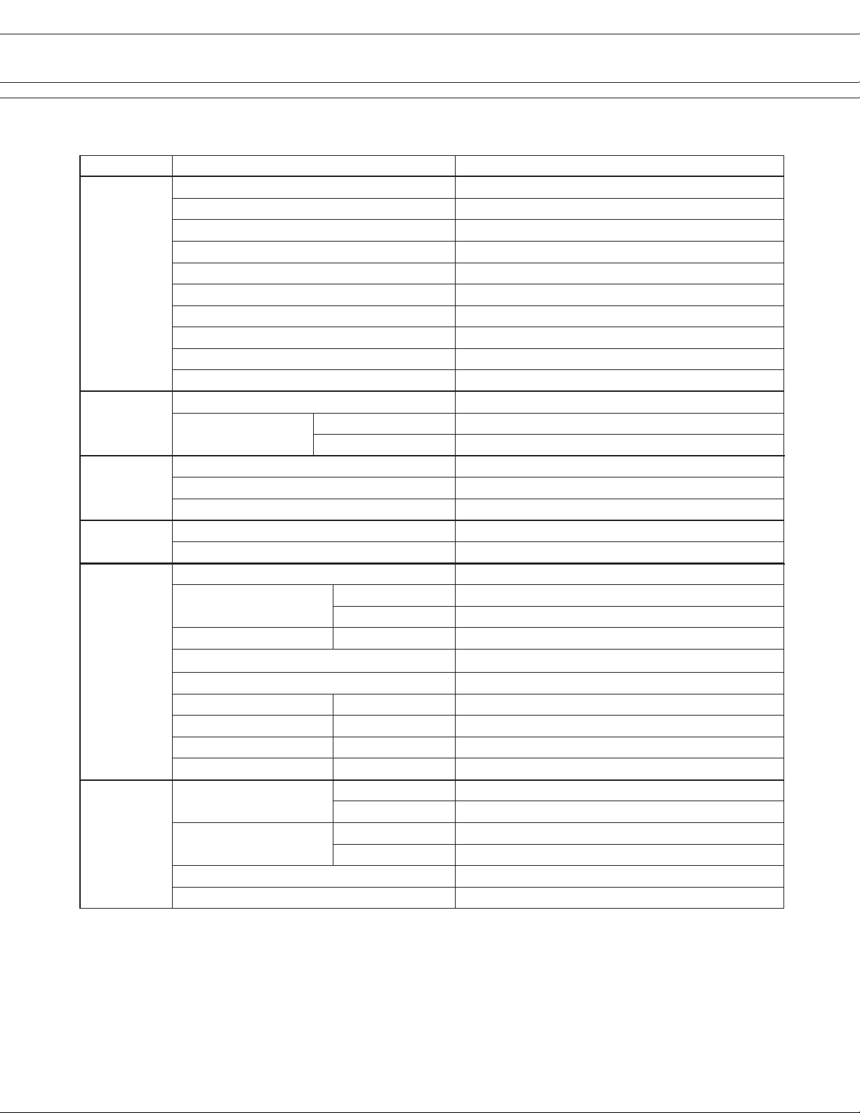
n SPECIFICATION
Item FTR-K2GAK ( ) T
Contact
Data
Life Mechanical 1 x 10⁶ operations minimum
Coil Data Rated power Approximately 1,000mW
Timing Data Operate (at nominal voltage) Max. 30ms (without bounce)
Insulation Resistance (initial) Min. 1,000MOhm at 500VDC
Other
Conguration 1 form A (SPST-NO)
Construction Single
Material AgSnO2
Resistance (initial) Maximum 100mOhm at 1A, 6VDC
Contact rating (resistive) 20A / 250VAC
Max. carrying current *¹ 25A
Max. inrush current 120A / 250VAC
Max. switching voltage 440VAC
Max. switching power 5,000VA
Min. switching load *² 100mA, 5VDC (reference value)
Electrical
Operate power Approximately 420mW
Operating temperature range -40 °C to +70 °C (no frost)
Release Max. 15ms (without diode)
Dielectric strength
Surge strength Coil to contacts 10,000V / 1.2 x 50µs standard wave
Clearance 8 mm
Creepage 9.5 mm
EN61710-1, VDE0435 Voltage 250V
Vibration resistance
Shock
Weight Approximately 34g
Sealing Flux proof, RT II
Resistive 100 x 103 operations minimum
Lamp load (TV-8) 25 x 103 operations minimum
Open contacts 2,000VAC (50/60Hz) 1min
Coil to contacts 5,000VAC (50/60Hz) 1min
Pollution degree 3
Material group III a
Category B / 250V
Misoperation>1us 10 to 55Hz double amplitude 1.5mm
Endurance 10 to 55Hz double amplitude 1.5mm
Misoperation>1us 100m/s² (11 ± 1ms)
Endurance 1,000m/s² (6 ± 1ms)
* 1 Need to consider the heat when mounted on PCB at carry currents > 10A. Please conrm actual condition.
* 2 Minimum switching loads mentioned above are reference values. Please perform the conrmation test with actual
load before production since reference values may vary according to switching frequencies, environmental contions
and expected reliability levels.
2
Page 3
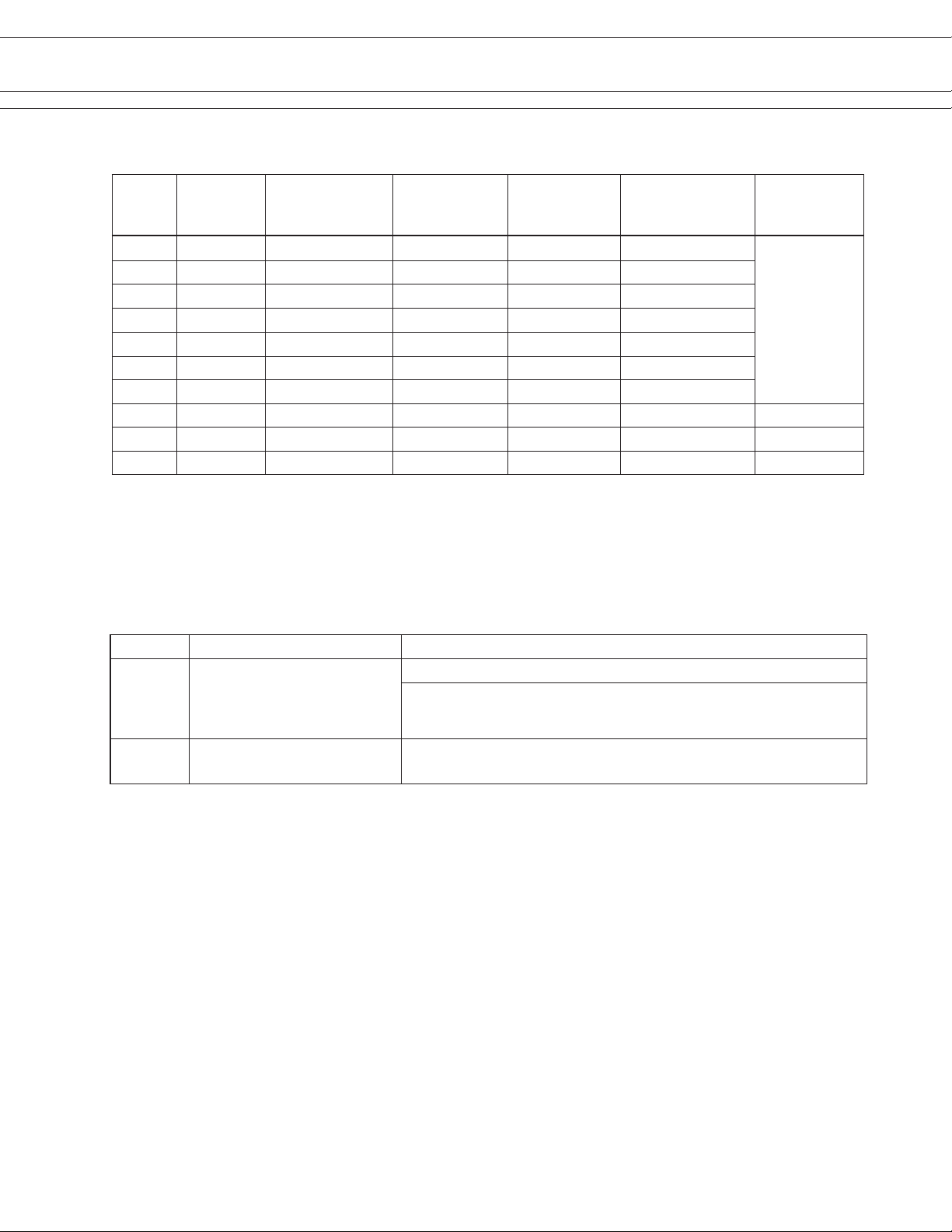
n COIL RATING
FTR-F4 SERIES
FTR-K2G SERIES
FTR-K1 SERIES
Coil
Code
005 5 25 3.25 0.25 8.5
006 6 36 3.9 0.3 10.2
009 9 81 5.85 0.45 15.3
012 12 145 7.8 0.6 20.4
018 18 325 11.7 0.9 30.6
022 22 485 14.3 1.1 37.4
024 24 580 15.6 1.2 40.8
048 48 2,200 31.2 2.4 81.6 1,050
060 60 3,600 39 3 102 1,000
110 110 13,000 71.5 5.5 187 930
Note: All values in the tables are valid for 20°C and zero contact current.
* Specied operate values are valid for pulse wave voltage.
Rated Coil
Voltage
(VDC)
Coil Resistance
+/- 10% (Ohm)
Must Operate
Voltage
(VDC) *
Must Release-
Voltage
(VDC) *
Max. Coil Voltage
(VDC)
Rated Power
n SAFETY STANDARDS
(mW)
1,000
Type Compliance Contact rating
UL UL 508
CSA22.2 No.14
UL/CSA60950-1
E63614
VDE 0435, 0631, 0700, 0860
400 22822
Flammability: UL 94-V0 (plastics)
20A, 277VAC (resistive)
TV-8, 120 VAC
20A, 250 VAC (cosφ=1) 70°C 100k operations
8/120A, 250VAC 70°C 30k operations
3
Page 4

n CHARACTERISTIC DATA
FTR-F4 SERIES
FTR-K2G SERIES
FTR-K1 SERIES
n REFERENCE DATA
4
Page 5

n DIMENSIONS
FTR-F4 SERIES
FTR-K2G SERIES
FTR-K1 SERIES
l Dimensions
l Schematics
(BOTTOM VIEW)
l PC board mounting
hole layout
(BOTTOM VIEW)
Unit: mm
5
Page 6

FTR-F4 SERIES
FTR-K2G SERIES
FTR-K1 SERIES
RoHS Compliance and Lead Free Information
1. General Information
l All signal and power relays produced by Fujitsu Components are compliant with RoHS directive 2002/95EC
including amendments.
l Cadmium as used in electrical contacts is exempted from the RoHS directives on October 21st, 2005.
(Amendment to Directive 2002/95/EC)
l All of our signal and power relays are lead-free. Please refer to Lead-Free Status Info for older date codes
at: http://www.fujitsu.com/us/downloads/MICRO/fcai/relays/lead-free-letter.pdf
l Lead free solder plating on relay terminals is Sn-3.0Ag-0.5Cu, unless otherwise specied.
This material has been veried to be compatible with PbSn assembly process.
2. Recommended Lead Free Solder Prole
l Recommended solder Sn-3.0Ag-0.5Cu.
Flow Solder condition:
Pre-heating: maximum 120˚C
Soldering: dip within 5 sec. at
260˚C solder bath
Solder by Soldering Iron:
Soldering Iron
Temperature: maximum 360˚C
Duration: maximum 3 sec.
We highly recommend that you conrm your actual solder conditions
3. Moisture Sensitivity
l Moisture Sensitivity Level standard is not applicable to electromechanical relays, unless otherwise indicated.
4. Tin Whiskers
l Dipped SnAgCu solder is known as presenting a low risk to tin whisker development. No considerable length
whisker was found by our in house test.
6
Page 7

FTR-F4 SERIES
FTR-K2G SERIES
Fujitsu Components International Headquarter Ofces
FTR-K1 SERIES
Japan
Fujitsu Component Limited
Gotanda-Chuo Building
3-5, Higashigotanda 2-chome, Shinagawa-ku
Tokyo 141, Japan
Tel: (81-3) 5449-7010
Fax: (81-3) 5449-2626
Email: promothq@ft.ed.fujitsu.com
Web: www.fcl.fujitsu.com
North and South America
Fujitsu Components America, Inc.
250 E. Caribbean Drive
Sunnyvale, CA 94089 U.S.A.
Tel: (1-408) 745-4900
Fax: (1-408) 745-4970
Email: components@us.fujitsu.com
Web: http://us.fujitsu.com/components
©2010 Fujitsu Components Europe B.V. All rights reserved. All trademarks or registered trademarks are the property of their respective
owners.
The contents, data and information in this datasheet are provided by Fujitsu Component Ltd. as a service only to its user and only for general information purposes.
The use of the contents, data and information provided in this datasheet is at the users’ own risk.
Fujitsu has assembled this datasheet with care and will endeavor to keep the contents, data and information correct, accurate, comprehensive, complete and up to date.
Fujitsu Components Europe B.V. and afliated companies do however not accept any responsibility or liability on their behalf, nor on behalf
of its employees, for any loss or damage, direct, indirect or consequential, with respect to this datasheet, its contents, data, and information
and related graphics and the correctness, reliability, accuracy, comprehensiveness, usefulness, availability and completeness thereof.
Nor do Fujitsu Components Europe B.V. and afliated companies accept on their behalf, nor on behalf of its employees, any responsibility
or liability for any representation or warrant of any kind, express or implied, including warranties of any kind for merchantability or tness for
particular use, with respect to these datasheets, its contents, data, information and related graphics and the correctness, reliability, accuracy,
comprehensiveness, usefulness, availability and completeness thereof. Rev. July 21, 2010
Europe
Fujitsu Components Europe B.V.
Diamantlaan 25
2132 WV Hoofddorp
Netherlands
Tel: (31-23) 5560910
Fax: (31-23) 5560950
Email: info@fceu.fujitsu.com
Web: emea.fujitsu.com/components/
Asia Pacic
Fujitsu Components Asia Ltd.
102E Pasir Panjang Road
#01-01 Citilink Warehouse Complex
Singapore 118529
Tel: (65) 6375-8560
Fax: (65) 6273-3021
Email: fcal@fcal.fujitsu.com
Web: http://www.fujitsu.com/sg/services/micro/components/
7
 Loading...