

Page 1

C150-E100-01EN
M3097DE/DG Image Scanner
Operator's Guide
Page 2

M3097DE/DG
Image Scanner
Operator's Guide
Page 3

01
Date publishedEdition
December, 1997 First edition
Revised contents
Specification No. C150-E101-01EN
This equipment has been tested and found to comply with the limits for a Class A
digital device, pursuant to Part 15 of the FCC Rules. These limits are designed to
provide reasonable protection against harmful interference when the equipment is
operated in a commercial environment. This equipment generates, uses, and can
radiate radio frequency energy and, if not installed and used in accordance with the
instruction manual, may cause harmful interference to radio communications.
Operation of this equipment in a residential area is likely to cause harmful
interference in which case the user will be required to correct the interference at his
own expense.
This digital apparatus does not exceed the Class A limit for radio noise emissions
from digital apparatus set out in the Radio interference Regulations of the Canadian
Department of Communications.
Le pésent appareil numérique n’ément pas de bruits radioélectriques dépassant les
limites applicables aux appareils numériques de la classe A prescridtes dans le
Réglesment sur le brouillage radioélectrique dicté par le ministere des Communications du Canada.
MaschinenlärmInformationsverordnung 3. GSGV, 18.01.1991:Der arbeisplatzbezogene Schalldruckpegel beträgt 70dB(A)oder weniger gemäß ISO 7779.
The contents of this manual may be revised without prior notice.
All Rights Reserved, Copyright © 1997 FUJITSU LIMITED.
Printed in Japan.
No part of this manual may be reproduced in any form without permission.
i
Page 4

Please send your comments on this manual or on Fujitsu products
to the following addresses:
FUJITSU COMPUTER PRODUCTS OF
AMERICA,INC.
2904 Orchard Parkway,San Jose.
California 95134-2022,U.S.A.
TEL:1-408-432-6333
FAX:1-408-432-3908
Home page:http://www.fcpa.com/
FUJITSU AUSTRALIA LIMITED
475 Victoria Avenue Chatswood.
N.S.W2067,AUSTRALIA
TEL:61-2-410-4555
FAX:61-2-411-8603
FUJITSU CANADA,INC.
2800 Matheson Blvd.East,Mississauga.
Ontario 4X5,CANADA
TEL:1-905-602-5454
FAX:1-905-602-5457
FUJITSU DEUTSCHLAND GmbH.
Frankfurter Ring 211,
8000 München 40,F.R,GERMANY
TEL:49-89-32378-0
FAX:49-89-32378-100
FUJITSU ESPAÑA,S.A
Edificio torre Europa 5
Paseo de la Castellana 95 Madrid 28046,SPAIN
TEL:34-1-581-8400
FAX:34-1-581-8125
FUJITSU EUROPE LTD.
2,Longwalk Road,Stockey Park,Uxbridge
Middlesex,UB11 1AB,U.K
TEL:44-81-573-4444
FAX:44-81-573-2643
Home page:http://www.fujitsu-europe.com/
a
FUJITSU FRANCE S.A.
Bâtiment Aristote,17 rue Olof palme
94006 Créteil cedex,FRANCE
TEL:33-14-513-1616
FAX:33-14-399-0700
FUJITSU HONG KONG Limited
Room 2521,Sum Hung Kai Centre
30 Harbour Road Wanchal,Hong Kong
TEL:852-827-5780
FAX:852-827-4724
TLX:62667
FUJITSU ITALIA S.p.A.
Via Melchiorre Gioia,No.8-20124
Milano,ITALY
TEL:39-2-6351
FAX:39-2-6572257
FUJITSU NORDIC AB
Kung Hans vag,S-19176
Sollentuna,SWEDEN
TEL:46-8-626-6000
FAX:46-8-626-6711
FUJITSU LIMITED
International Operations
Marunouchi 1-6-1, Chiyoda-ku,Tokyo 100
JAPAN
TEL:(81-3)3216-3211
FAX:(81-3)3213-7174
TLX:J2283
Cable:”FUJITSU LIMITED TOKYO”
Home page:http://www.fujitsu.co.jp/
ii
Page 5

IMPORTANT NOTE TO USERS
READ CAREFULLY ALL OF THIS MANUAL BEFORE USING THIS PRODUCT.
IF NOT USED CORRECTLY, UNEXPECTED DAMAGES MAY BE CAUSED TO
THE USERS OR THE BYSTANDERS.
While all efforts have been made to ensure the accuracy of all information in this
manual, FUJITSU assumes no liability to any party for any damage caused by
errors or omissions or by statements of any kind in this manual, its updates or
supplements, whether such errors are omissions or statements resulting from
negligence, accidents, or any other cause. FUJITSU further assumes no liability
arising from the application or use of any product or system described herein; nor
any liability for incidental or consequential damages arising from the use of this
manual. FUJITSU disclaims all warranties regarding the information contained
herein, whether expressed, implied, or statutory.
FUJITSU reserves the right to make changes to any products herein, to improve
reliability, function, or design, without further notice and without obligation.
iii
Page 6

Preface
This manual explains how to use the M3097DE/DG image scanner.
This manual contains COMPONENTS, INSTALLATION AND CONNEC-
TION, OPERATING INSTRUCTION,DOCUMENT SPECIFICATION,
SPECFICATIONS and SETUP MODE.
Refer to “Cleaning and Maintenance” for the information about the routine
operation of the M3097DE/DG.
Reference Guide contains OPERATING INSTRUCTION, CLEANING,
REPLACEMENT OF PARTS, ADJUSTMENT and TROUBLESHOOTING.
The M3097DE/DG is very fast and highly functional image scanner developed for volume filing, using charge-coupled device (CCD) image sensors.
This scanner features duplex scanning and high quality image, processing
with an automatic document feeder (ADF).
iv
Page 7

Conventions
Special information, such as warnings, cautions are indicated as follows:
WARNING
WARNING indicates that personal injury may result if you do not follow a
procedure correctly.
CAUTION
CAUTION indicates that damage to the scanner may result if you do not follow a
procedure correctly.
The following symbols are used in this manual.
Used for general WARNING and CAUTION.
Be careful not to pinch your fingers or hands.
v
Page 8

vi
Page 9

CONTENTS
❑ CHAPTER 1 COMPONENTS
❑ CHAPTER 2 INSTALLATION AND CONNECTIONS
❑ CHAPTER 3 OPERATING INSTRUCTION
Checking the Components ........................................................1-1
Units and Assemblies ................................................................1-2
Operator Panel ..........................................................................1-5
Precautions................................................................................2-1
Inspection ..................................................................................2-2
Removing the Carrier Fixing Bracket.........................................2-4
Cable Connection ......................................................................2-5
Mounting the Stacker.................................................................2-7
SCSI-ID setting (M3097DG) ......................................................2-8
Turning the Power On ...............................................................3-1
Reading Mode Setting (M3097DE)............................................3-2
Manual Feed Mode Setting .......................................................3-8
❑ CHAPTER 4 ADF DOCUMENT SPECIFICATION
Document Size ..........................................................................4-1
Document Quality ......................................................................4-2
❑ CHAPTER 5 SPECIFICATIONS
Installation Specifications ..........................................................5-1
Dimensions................................................................................5-2
Consumables.............................................................................5-3
Option ........................................................................................5-4
❑ CHAPTER 6 SETUP MODE
Activating the Setup Mode.........................................................6-1
Contents of the Setup Mode......................................................6-2
❑ GLOSSARY OF TEAMS................................................................................GL-1
❑ INDEX ............................................................................................................. IN-1
vii
vii
Page 10

viii
Page 11

COMPONENTS
INSTALLATION AND CONNECTIONS
OPERATING INSTRUCTION
DOCUMENT SPECIFICATION
SPECIFICATIONS
SETUP MODE
COMPONENTS
INSTALLATION AND
CONNECTIONS
OPERATING
INSTRUCTION
DOCUMENT
SPECIFICATION
SPECIFICATIONS
SETUP MODE
GLOSSARY OF TERMS
INDEX
GLOSSARY
OF TERMS
INDEX
ix
ix
Page 12

CHAPTER
1
COMPONENTS
After unpacking the scanner,confirm that all the components have
been received. This chapter describes the components of the
scanner, part names, and operator panel arrangement and their
function.
Checking the Components
Units and Assemblies
Operator Panel
Page 13

1
Cheking the Components
These high precision components must be handled with care.
Confirm that all the components shown in the following figure have been received.
If any component is missing, please contact your sales agent.
Terminator
(for M3097DG)
Operator's Guide
(this manual)
and Cleaning and Maintenance
Scanner
Power cable
for North America
Power cable
for Europe
or
Pad ASY
1-1
Page 14

Units and Assemblies
This section shows the exterior view and assemblies of the scanner. This section also provides
names of each part and describes their functions.
Units
qDocument cover
rAutomatic document
feeder(ADF)
tStacker
yPower switch
iADF paper chute
!0Power inlet
eDocument
holding pad
wDocument bed
uOperator panel
oADF lever
!2Third party slot
!1Interface connectors
!3Memory cover
1-2
M3097DE
Page 15

oADF lever
iADF paper chute
yPower switch
!1Interface connectors
!0Power inlet
No. Function
q Document cover: Closed over and holds a document to be read.
w Document bed: A document to be read is placed on the bed also called
e Document holding pad: Presses a document to the document bed.
r Automatic document feeder (ADF): Automatically feeds documents to the reading position.
t Stacker: Stacks the read documents.
y Power switch: Turns the power on or off.
u Operator panel: The indication panel indicates the status of the scanner.
i ADF paper chute: Holds the documents to be fed by the automatic
o ADF lever: Opens or closes the automatic document feeder to
!0 Power inlet: To be connected to an AC power outlet with the power
!1 Interface connectors: To be connected to the host system with interface cables.
!2 Third party slot: Reserved. (M3097DE)
!3 Memory cover: Reserved.
!3Memory cover
M3097DG
Flatbed (FB).
document feeder.
remove documents jammed in the feeder.
cable.
1-3
Page 16

Assemblies
Stacker
Thumb screw
Guide A ASY
Bearing
Pick roller 2
Pad ASY
1-4
Bearing
Pick roller 1
Page 17

Operator Panel
The operator panel is located at the upper right hand side of the scanner. The panel consists of an
LCD (24 character x 2 line), LEDs and buttons.
Arrangement
Operator panel
( )
Previous
( )
Next
(STOP)
Exit
(START)
ENTER
READ
CHECK
1-5
Page 18

Button/LED Function
Name of the button Function
and LED
Button Next LCD displays the next screen.
Previous LCD displays the Previous screen.
← Moves the cursor to the left
→ Moves the cursor to the right
Exit • When “CHECK” LED lights, pressing this button releases error status (turn
off “CHECK” and returns to “Scanner Readry” screen).
• When you are setting on the operator panel, pressing this button returns to
“Scanner Ready” screen immediately.
ENTER The parameter selected by cursor becomes effective.
(START) When Manual start mode is set or “READ” lamp lights, this button is effective
and starts the reading.
(STOP) This button is effective during reading operation and stops the reading.
LED Indicates that the scanner is ON.
READ Indicates that the scanner is reading or ready to read.
CHECK • If it lights, it means that some alarm occurred. Pressing “Exit” button turns
off “CHECK” lamp.
• If it blinks at one second cycle, it means that jam or double feed is
detected. Removing the jammed paper turns off “CHECK” lamp. At double
feed, pressing “Exit” button turns off “CHECK” lamp.
• If it blinks at four seconds cycle, it means that ADF cleaning is necessary.
1-6
Page 19

Counter Display
The scanner is provided with the counter display.
Paper counter
Abrasion counter
Counter Function
Paper counter Paper counter counts the scanned sheet from the start of reading to Paper
Empty or an error detection. So this counter is automatically reset at the start
of reading.
Abrasion counter Abrasion counter counts the accumulated number of the scanned sheet. This
counter increments at every 10 sheets. This counter is useful to check the
cleaning cycle or parts replacement cycle. How to reset is described in Chapter 6.
1-7
Page 20

Operation status
Operation status is indicated by the following message:
<Power-on>
<Reading>
<Waiting for Start> Scanner displays followig screen when waiting Start button pressed.
(Only M3097DE)
<Cleanig request> When the Pick roller cleaning is necessary, the scanner displays as
follows on the upper line.
When the ADF glass cleaning is necessary, the scanner displays as
follows on the LCD.
1-8
Clean the Pick roller or ADF glass in accordance with the manual,
“Cleaning and Maintenance”.
Page 21

Temporary error
<Hopper empty>
<Jam>
<ADF cover open>
<Double feed error>
This message is displayed if there is no more paper on the ADF paper
chute during a read operation in ADF mode. Fill the ADF paper chute
with paper. To enable the read operation, press the stop button.
This message is displayed if a ducument is jammed in the ADF. See
“Cleaning and Maintenance” for removing jammed ducuments.
This message is displayed if the ADF is not closed completely. Close
the ADF completely, and enable the read operation.
This message is displayed when the ADF detects the Double feed
error. Check the document and re-scan the ducument.
1-9
Page 22

Alarm
One of the following message is displayed if an error occurs in the scanner. If one of the following
error message is displayed, turn the power off and then on again. If the same message is displayed,
contact your service representative.
<Optical alarm front>
<Optical alarm back>
<FB mechanism alarm>
<Motor fuse alarm>
<Lamp fuse alarm>
<Image transfer alarm>
(M3097DG)
<Memory alarm>
<EEPROM alarm>
1-10
Page 23

CHAPTER
2
INSTALLATION AND CONNECTIONS
The chapter describes how to install and connect the scanner.
Precautions
Inspection
Removing the Carrier Fixing Bracket
Cable Connection
Mounting the Stacker
SCSI-ID Setting (M3097DG)
Page 24

Precautions
This section describes precautions when installing the scanner.
Do not install the scanner in the following places and environments.
• Place the scanner away from electrical noise sources, strong magnetic fields and air flow. If the scanner
is used near an air conditioner, copying machine, or TV set, the scanner may operate incorrectly.
• Keep the scanner out of the sun and away from heaters. These environments may shorten the scanner
life or cause hardware failures.
• Do not install the scanner in a place where vibrations may occur. This environment may cause hardware
failures or may cause the scanner to operate incorrectly.
• Do not install the scanner in a humid, dusty, or damp places. These environments may shorten the
scanner life or cause hardware failures. Do not place the scanner where liquid spills may occur.
• Be aware of the static electricity. Be sure that the flooring and the desk are made of materials that do
not generate the static electricity.
See Chapter 5 SPECIFICATIONS for the informantion such as the size of the installation space.
2-1
Page 25

Inspection
This section describes how to check the labels.
Label A (An example)
Label A
Label B
2-2
This device complies with Part 15 of the FCC Rules. Operation is subject to the following two conditions:
(1) This device may not cause harmful interferenca and (2) This device must accept any Interference
received, including interference that may cause undesired operations:
This Class A digital apparatus meets all taquiraents of the Canadian Interferance Causing Equipment Regulations.
Cat appareil auncrique de la classe A respecte loutes les exigences du Reglesent sur le nateriel
bronillesr du Canada.
LR 65408
NRTL/C
N
1 2 4
XXXXXXXX
XXXXX
XXXXXX
VCCI-A
FCC-A
CSA-EMI
ANS
100 - 240 V, 1 - 0.6A. 50/60 Hz, 1φ
Page 26
Label B (An example)
IMAGE SCANNER
MODEL
M3097DE
PART NO.
CAO
**** - ****
SER. NO.
*****
DATE
1997-
2 .
** * *
Kgf
FUJITSU LIMITED
MODEL NAME
Rev.
Label
0123456789
0123456789
0123456789
ANS
2-3
Page 27

Removing the Carrier Fixing Bracket
(
)
To keep the scanner from being damaged during shipping, the carrier unit is fixed with a bracket. After
placing the carrier unit at the installation place, remove this bracket as explained below.
q Place the image scanner on the edge of the desk top so that the left side (where ADF is placed)
of the scanner extends from the desk top. Do not set the image scanner upside down or on its side.
CAUTION
Do not extend the scanner more than 20cm (8 in.) from the desk.
Good
less than 20cm
8 in.
Bad Bad
w Remove the carrier fixing bracket from position A. Then install the carrier fixing bracket at position
B.
Front side
Enlarged
Carier fixing bracket
(Position for operation)
Bottom view
Carier bracket (Position for
storage, position for shipment)
Enlarged section A enlarged
ADF side
B
2-4
A
Carier bracket
(Position for shipment)
Page 28
Cable Connection
This section describes how to connect the cables.
Connect the cables as follows:
Turning the power switch off
Press “O” side of the power switch to turn the power off.
Power switch
Power OFF
Power ON
Connecting the power cable
Connect the power cable to the power inlet of the device and a power outlet.
for North America
Power inlet
Power cable
Power outlet
for Europe
2-5
Page 29
Connecting the interface cable
(M3097DE)
Connect the video interface and RS-232C interface cables and secure them with hooks and screws.
Connect the other ends to the host machine.
Back of the image scanner
Catches
Interface cable for video
Interface cable for RS232C
Screws
To the host system
(M3097DG)
Connect the SCSI interface cables and secure them with hooks and connect the other ends to the host
machine. When the scanner is at the terminal side, connect the terminator to the connector to which an
interface cable is not connected.
Back of the image scanner
Terminator
If the image scanner is at
Catches
Interface cables
To
the host
system
the terminal side, connect
the terminator to the
connector to which an
interface cable is not
connected.
2-6
Page 30
Mounting the Stacker
Mount the stacker using the following procedure.
q Mount the stacker.
Hook the pins on the stacker to the claws on the image scanner.
Stacker
Pin (inside)
Claw
2-7
Page 31
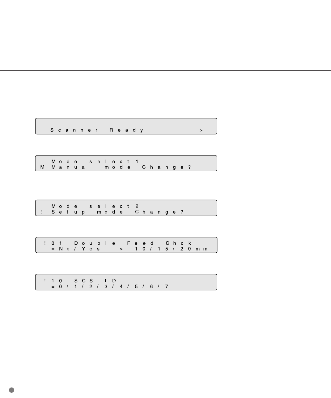
SCSI-ID setting (M3097DG)
The default of SCSI-ID is 5. SCSI-ID is set by Setup mode of the operator panel. The procedure to set SCSI
ID is;
1 Turn the power ON by pressing “I” side of the power switch. The scanner displays “Scanner Ready”
on the lower line of LCD.
2 Then press “Next” button. The scanner displays “Mode select 1”.
3 Then press “Next” button. The scanner displays “Mode select 2” meaning that setup mode is ready.
Then press “ENTER” button.
4 Then press “ENTER” button. The scanner displays as follows.
5 Press “Previous” once, then the scanner displays “SCSI ID” on the upper line of the LCD.
6 Select SCSI ID by pressing “→” or “←” button, and press “ENTER”. (SCSI ID is set.)
7 Press “Exit” to return to “Scanner Ready” screen.
2-8
Page 32

CHAPTER
3
OPERATING INSTRUCTION
This chapter describes how to turn the power on, and also describes button specification and reading mode setting.
Refer to Cleaning and Maintenance about information on loading
document and maintenance.
Turning the Power On
Reading Mode Setting (M3097DE)
Manual Feed Mode Setting
Page 33

3
Turning the Power On
This section describes how to turn the power on.
Press “I” side of the power switch. The power goes on and the green Power lamp at the operator
panel lights.
Power OFF
Power switch
Power ON
3-1
Page 34

Reading Mode Setting (M3097DE)
This section describes the button specifications and setup details for each of the simplex (front-side),
duplex (front-side) and duplex (back-side) reading modes.
When reading mode is set by the command from the host computer, the following button operation is
not required.
At any time you press , scanner returns to screen M1
1 Turn the power ON and verifty that
“Scanner Ready” is displayed on LCD.
2 Press then the scanner displays
Screen M2.
3 Press then the scanner displays
Screen 1.
4 Select ADF or FB by pressing or
then press . The scanner displays
Screen 2.
5 Select “Simplex” or “Duplex” by pressing
or . Then press Enter. The scan-
ner displays Screen 3.
<Screen M1>
<Screen M2>
<Screen 1>
<Screen 2>
6 Select “Portrait” or “Landscape” by
pressing or . Then press .
The scanner displays Screen 4.
3-2
<Screen 3>
Page 35

7 Select Size by pressing or . Then
press . The scanner displays
Screen 5.
<Screen 4>
8 Select Resolution by pressing or .
As the cursor moves to left 100/150 may
appear. Then press . The scanner
displays Screen 6.
9 Select Front Density by pressing or
. As the cursor moves to right,
/ may appear. Then press Enter.
Scanner displays Screen 7.
Density display
Without IPC With IPC-2D Descreption
option or IPC-3D option
Very dark
Dark
AT1 * Dynamic Threshold (DTC mode)
AT2 * Simplified Dynamic Threshold (IPC mode)
Normal
Light
Very light
* This parameter appears only when IPC-2D or IPC-3D is installed.
<Screen 5>
<Screen 6>
3-3
Page 36

10 Select Back Density (when “Duplex” was
Selected) by pressing or . As the
cursor moves to right, /
may appear. Then press . Scanner
displays Screen 8.
<Screen 7>
11 Select Front Halftone by pressing or
.
Parameter Description
No Halftone is OFF. Therefore binary reading is specified.
HT1 Halftone with dither is specified.
HT2 Halftone with error diffusion is specified.
LP1 * Automatic separation with dither is specified.
LP2 * Automatic separation with error diffusion is specified.
* This parameter appears only when the IPC-2D or IPC-3D is installed.
Press to admit. Scanner displays
Screen 9.
12 Select Back Halftone (when “Duplex” was
specified) by pressing or . The
parameters are same as 11. Press
to admit. Then scanner displays Screen
10.
<Screen 8>
<Screen 9>
13 Select Front Document Type by pressing
or .
3-4
<Screen 10>
Page 37

Parameter Description
L.(Line) White level following is ON. Top 3mm part of the document must be left blank
(grounding color is dropout color). It is useful to read line art or text.
P.(Photo) White level following is OFF.
It is useful to read photograph.
Press to admit. The scanner displays
Screen 11.
14 Select Back Document Type (when
“Duplex” was specified) by pressing
or . The parameters are same as (13).
Press to admit. Then scanner
displays Screen 12.
15 Confirm what you have specified.
If some parameter needs to change,
press or to select screen
and re-select the parameter by pressing
or and finally press .
If all parameter is acceptable, press
to return to “Scanner Ready” screen.
<Screen 12>
<Screen 12 (Example)>
Density
Halftone
Line Art or Photo
Resolution
Portrait or Landscape
Paper size
Front side (F) or Back side (B)
Simplex (S) or Duplex (D)
3-5
Page 38

Manual Feed Mode Setting
In this mode, the scanner waits for some predetermined time without issuing “Paper Empty” after all
documents are read. This predetermined time (time-out limit) is specified by Setup mode. Therefore
you can set next documents on ADF chute without interrupting reading operation. The procedures for
setting manual feed mode are as follows.
1 Turn the power ON and verify that
“Scanner Ready” is displayed on LCD.
2 Press then the scanner displays
Screen M2.
3 Press then the scanner displays
Screen M3.
4 Press then the scanner displays
Screen M4.
5 Select “Yes” by pressing . Then press
.
<Screen M1>
<Screen M2>
<Screen M3>
<Screen M4>
6 Press to return to “Scanner Ready”
screen. Note that “Manual Feed” is
shown on LCD. This means that the
scanner is in Manual Feed mode.
3-6
<Screen M1>
Page 39

CHAPTER
4
ADF DOCUMENT SPECIFICATION
This chapter describes the document size and document guality
of the ADF.
Document Size
Document Quality
Page 40

Document Size
The following figure shows document sizes that the scanner can read.
Scanner
M3097DE/DG
Maximum
A
297 (11.7 in)
B
432 (17 in)
Minimum
A
148 (5.8 in)
105 (4.1 in)
B
105 (4.1 in)
148 (5.8 in)
(Unit : mm)
4-1
Page 41

Document Quality
This section describes document types and weights available for the scanner, and precautions.
Document type
The recommended paper type for document is as follows:
• Woodfree paper
• Plain paper (for example, the paper specified for XEROX 4024)
When using all other type paper, check that it is successfully fed by ADF before performing a reading
operation.
Paper weight
The paper weight is as follows :
• 52 to 104 g/m2 (3.9 to 27.8 lb)
Precautions
The following documents may be hard to read by ADF. Preliminary document feed test may be necessary
to avoid the unexpected errors. If the document slips in ADF (JAM error) or double feed occurs frequently,
read them by flatbed.
• Paper with clips or staple
• Paper with wet ink
• Paper of which thickness is not constantly equal. (like envelope)
• Paper with large rumples or curl. (See NOTE on the next page.)
• Paper with folds or tears
• Tracing paper
• Coating paper
• Carbon paper
• Paper smaller than 148 mm x 105 mm size, or larger than A3 or Double Letter
• Other than paper ; clothes, metal foil, or OHP film
• Photographic paper
• Paper with notches on its side
• Other than rectangle paper
• Paper that is very thin
4-2
Page 42
CAUTION
Do not feed an important original document to prevent damage to it on the
off chance.
When scanning a translucent document, set the density to light mode.
Carbon-less papers have the chemical composition which damages the pad and pick roller. Therefore,
note the following remarks
Cleaning: If the miss pick occurs frequently, clean the pad and pick roller in accordance with
the “Cleaning and Maintenance”.
Replacement of parts: The life of the pad and the pick roller may be shorter than the case that PPC
document is fed.
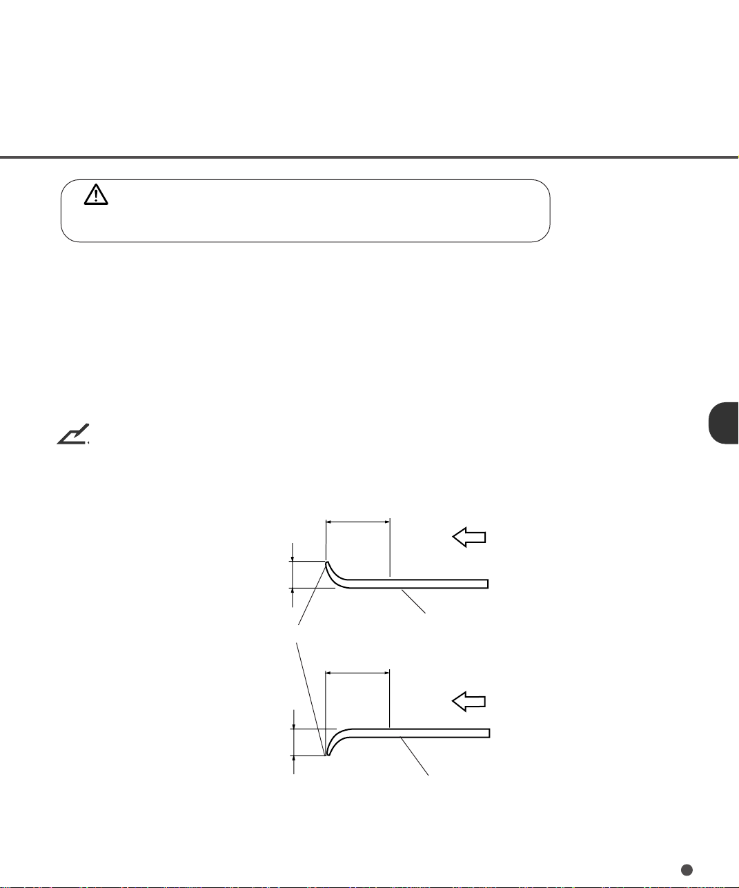
NOTE
• Paper should be straightened to fit the condition below.
More than
30 mm
Less than
3 mm
Top of the paper
Less than
5 mm
Feed direction
Read surface
More than
30 mm
Feed direction
Read surface
4-3
Page 43

4-4
Page 44

CHAPTER
5
SPECIFICATIONS
This chapter describes the installation specifications, dimensions, consumables, option.
Installation Specifications
Dimensions
Consumables
Option
Page 45
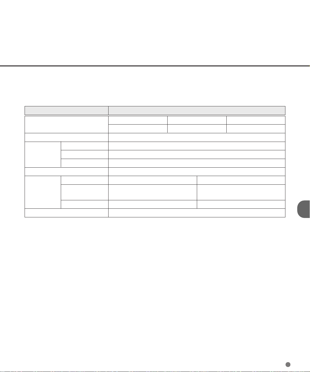
Installation Specifications
The following table lists the installation specifications of the scanner.
Item Specification
Dimensions (mm)
Weight (kg) 20 (44.2 lb.)
Voltage 100 to 120 VAC, 220 to 240 VAC ±10 %
Input power Phases Single-phase
Frequency 50/60 + 2% -4% Hz
Power consumption 120 VA or less
Device status Operating Not operating
Ambient Temperature 5 to 35°C -20 to 60°C
condition (41 to 95°F) (-4 to 140°F)
Humidity 20 to 80 % 8 to 95 %
Heat capacity 78 kcal/H (312 BTU/H)
Width Depth Height
696 (27.4 in) 497 (19.6 in) 234 (9.2 in)
5-1
Page 46
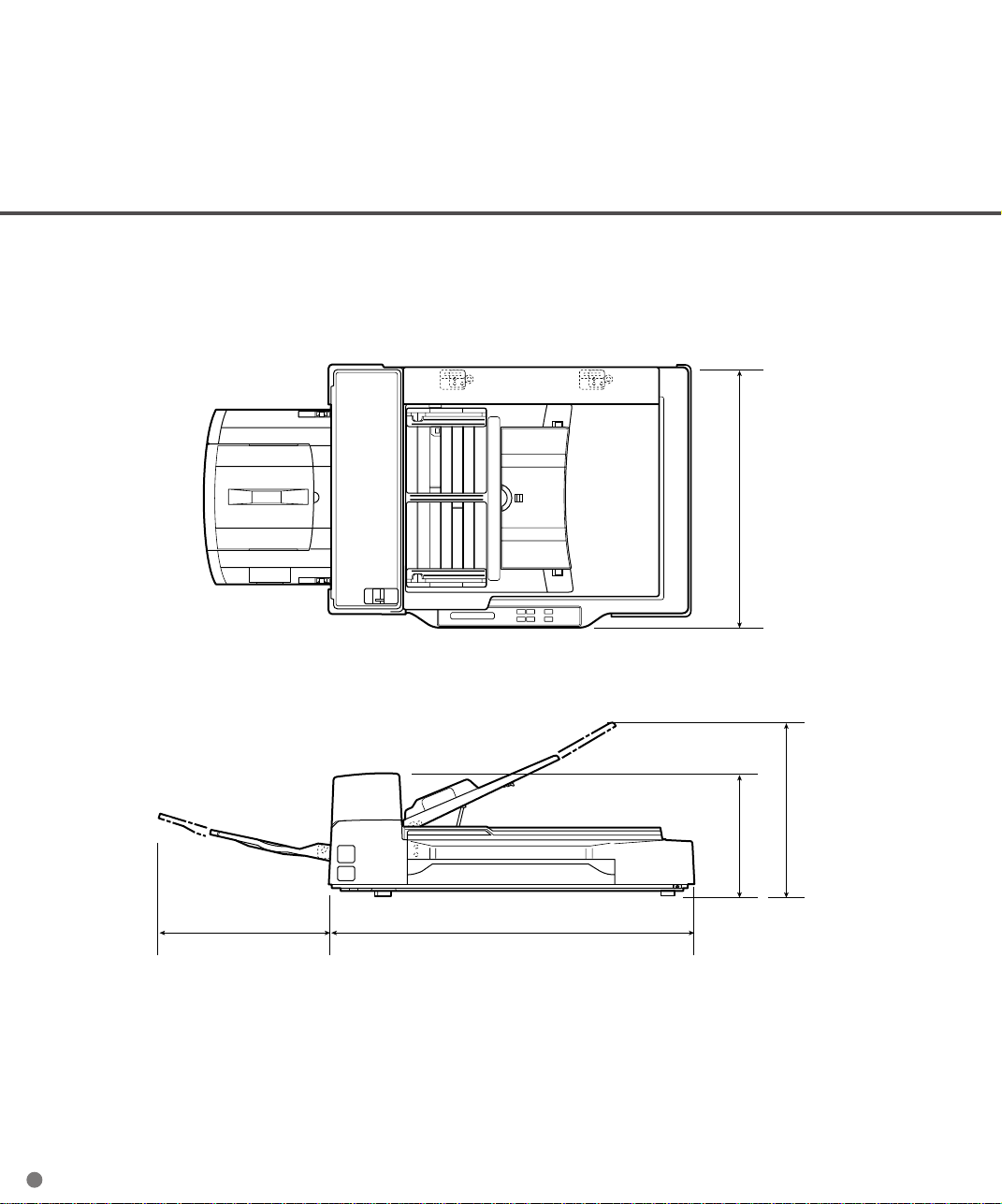
Dimensions
497
5-2
335
234
285 696
(unit: mm)
Page 47

Consumables
The following table lists consumables used for the scanner. Be sure to keep some consumables in stock.
Customer is responsible to change these items periodically. The abrasion counter can be used to check
the number of scanned documents.
Name Specification Remark
Pad ASY PA03951-0021 Up to 100,000 sheets or one year.
Pick roller PA03951-0025 Up to 200,000 sheets or one year.
(Two roller are included.)
5-3
Page 48

Option
The following table lists options of the scanner.
Name Specification Remark
Extended Memory TBD 16MB, EDO SIMM, 72pin, 60ns
IPC-2D* CA01952-0192 Image Processing Circuit
IPC-3D* CA02919-0511 Image Processing Circuit
* One of these option can be installed at a time
Contact your Fujitsu sales agent for more information.
without parity
One per unit
One per unit
One per unit
5-4
Page 49

CHAPTER
6
SETUP MODE
This chapter describes the setup mode of the scanner.
Activating the Setup Mode
Contents of the Setup Mode
Page 50

Activating the Setup Mode
This section describes how to activate the setup mode.
1 Turn the power ON. Then the scanner
displays “Scanner Ready” on LCD.
2 If the scanner is M3097DG, go to the
procedure 3. Press then the scanner (M3097DE) displays Screen M2.
3 Press then the scanner displays
Screen M3.
4 Press then the scanner displays
Screen M4.
5 Press . Now the scanner is at
Screen 41 (page 6-3) in Setup mode.
<Screen M1>
<Screen M2>
<Screen M3>
<Screen M4>
NOTE
Any time you press , you can return to “Scanner Ready” screen.
6-1
Page 51

Contents of the Setup Mode
This section describes the contents of the setup mode.
No Item Description Selectable Default
parameters
1 Double feed check Double feed is detected by checking the
document length one by one.**
2 IPC pre-setting Scanner automatically sets the recom-
mended reading parameters. 5 sets of
recommended parameters are available.
3 Rest of abrasion Abrasion counter can be reset.
counter
4 Pick start time The time from the document Insertion to
setting the start of picking is specified. User can
select most comfortable Pick start time for
the job.
5 Time-out limit setting The time that the scanner waits for next
ducument insertion after last document
scanned can be specified.
6 ADF front offset Horizontal and vertical offset of the front
setting* side image by ADF is specified.
7 ADF back offset Horizontal and vertical offset of the back
setting* side image by ADF is specified.
8 FB offset setting* Horizontal and vertical offset of the FB
image is specified.
9 IPC/Memory status The type of IPC option (IPC-2D or IPC-3D)
display and total memory installed are displayed.
10 SCSI ID setting SCSI ID is selectable.
Tolerance: No
No/10/15/20mm
Document: No
No/1/2/3/4/5
--
Time:
0.2 to 29.8 sec
Time:
27 values from 30 sec
1 to 1999 sec
Offset: Offset:
H:-2 to +3mm H: 0 mm
V:-2 to +3mm V: 0 mm
Offset: Offset:
H:-2 to +3mm H: 0 mm
V:-2 to +3mm V: 0 mm
Offset: Offset:
H:-2 to +3mm H: 0 mm
V:-2 to +3mm V: 0 mm
SCSI ID:
0/1/2/3/4/5/6/7 5
1.0 sec
* This offset means the deference from the value adjusted by automatic offset adjustment.
** The document length on ADF paper chute must be same. If the completely overlapped sheets are
fed, the scanner cannot detects the double feed.
6-2
Page 52

Setting double feed detection
When you set the using of double feed detection, you must set as follows:
1 Press or and let the
scanner display Screen 41.
2 At Screen 41, press or to select
the tolerance (10 or 15 or 20mm) and
press to activate the double feed
detecton. Scanner compares the length
of the scanned document with the length
of the first document. When the length of
the scanned document is longer or
shorter than the length of the first document exceeding the tolerance, double
feed is detected. If you want to disable
the double feed, select “No” then press
. Press to return to “Scanner
Ready” screen.
NOTE
Double Feed detection is effective only when the length of the all document on ADF is same.
<Screen 41>
NOTE
Scanner stops document feeding at the double feed detection. When the document in ADF is not the
double fed document, previous document may be double fed.
NOTE
If the completely overlapped sheets are fed, the scanner can not detect the double feed.
6-3
Page 53

Setting IPC pre-set mode
When you set the using of IPC-2 pre-set mode, you must set as follows:
1 Press or and let the
scanner display Screen 42.
2 At Screen 42, press or to select
<Screen 42>
the document number and press to
activate the IPC pre-setting. Then the
scanner displays Screen 42-1. Go to
procedure 3. If you want to disable the
IPC pre-setting, select “No” then press
. Finally press to return to
“Scanner Ready” screen.
3 At Screen 42-1, select “Yes” to activate
<Screen 42-1>
the IPC pre-setting or select “No” to
disable the IPC pre-setting. Note that
when you activate the IPC pre-setting,
the IPC setting by Host computer is
ignored. Finally press , then the
scanner displays next item, Screen 43.
<Classification of document number>
Document number are classified in line-art scanning as follows:
The horizontal axis shows the background density/color of paper.
The vertical axis shows the density of charcter/ line.
Background density
Normal← →Dark
Red Green Blue
Background color
Normal
Character
density
q - t are the document number set in setup mode.
q:Normal background
↑
↓
Light
and character.
w:Normal background
and light character.
6-4
e:Dark background
and normal-density
character.
r:Light character
on red paper.
t:Light character
on green paper.
Page 54

NOTE
• When IPC pre-set is executed in setup mode
Scanner checks that IPC-2D or IPC-3D are installed when the scanner enters in IPC pre-set.
If IPC-2D or IPC-3D is not installed, the scanner does not enter in IPC pre-set.
• When IPC pre-set mode is executed
When IPC pre-set mode is executed in online mode, the reading parameter is valid or invalid (Host
setting is invalid) as follows:
Reading parameter
Reading
mode
Valid
Invalid
DTC
Valid
Invalid
Conversion
Valid
Invalid
Tranfer
mode
Size
Sharpness
Transfer
rate
Portrait/
Landscape
Reading parameter
Outline
extraction
Resdution
Reading parameter
Picking
Overlay
Document
Start of
reading
selection
Simplified
DTC
Density
r patterns
Zooming
Line-art
/ Photo
Contrast
Halftone
Automatic
separation
6-5
Page 55

Reset of abrasion counter
When you reset the abrasion counter, you must set as follows:
1 Press or and let the
scanner display Screen 43.
2 At Screen 43;
If you want to reset the abrasion counter,
select “Yes” by or button and
press . Go to procedure 3.
If you do not want to reset the abrasion
counter, select “No” and press .
Finally press to return to “Scanner
Ready” screen.
3 At Screen 43-1;
If you want to reset the abrasion counter,
select “Yes” and press . If you do
not want to reset, select “No” and press
.
<Screen 43>
<Screen 43-1>
Setting pick start time
When you set the pick start time, you must set as follows:
1 Press or and let the
scanner display Screen 44.
2 At Screen 44, press to increase the
Pick start time or press to decrease
the Pick start time. Then press to
activate the setting. Finally press to
return to “Scanner Ready” screen.
6-6
<Screen 44>
Page 56
Setting time-out limit
1 Press or and let the
scanner display Screen 45.
2 At Screen 45, press to increase the
number or press to decrease the
time-out limit. Then press to
activate the setting. Finally press to
return to “Scanner Ready” screen.
Setting Offset
1 Press or and let the scan-
ner display as follows;
• Front Offset by ADF : Screen 46.
• Back Offset by ADF : Screen 47.
• Offset of Flatbed : Screen 48.
<Screen 45>
<Screen 46>
<Screen 47>
<Screen 48>
2 Select “Yes” by pressing or
button, and press . Then scanner
displays Screen A.
<Screen A>
6-7
Page 57

3 At Screen A, if you want to let the offset
return to default, select “Yes” otherwise
“No” then press . The scanner
displays Screen B.
<Screen B (Example of ADF Front Offset)>
<Screen B (Example of ADF Back Offset)>
<Screen B (Example of FB Offset)>
4 At Screen B, press to increase the
offset or press to decrease offset.
The increment or decrement is 0.5 mm.
Then press to activate the setting.
The scanner displays Screen C.
5 At Screen C, press to increase the
offset or press to decrease offset.
Then press to activate the setting.
The scanner displays the next item of the
setup mode.
<Screen C (Example of ADF Front Offset)>
<Screen C (Example of ADF Back Offset)>
<Screen C (Example of FB Offset)>
6-8
Page 58
Reviewing the IPC/Memory Status
1 Press or and let the
scanner display Screen 49.
2 Screen 49 displays the IPC option
installed and total image memory installed. Press to return to “Scanner
Ready” screen.
Setting SCSI-ID (M3097DG)
1 Press or ant let the scan-
ner display Screen 4A.
2 At Screen 4A, press or to select
SCSI-ID. Then press to activate the
setting. Finally press to return to
“Scanner Ready” screen.
<Screen 49 (Example of 32MB)>
(An example)
<Screen 50>
6-9
Page 59

6-10
Page 60

GLOSSARY OF TERMS
A4 size
A standard paper size used in Japan and other countries. Paper size is 210 x 297 mm (8.25 x 11.6 inches).
Abrasion counter
Indicates when belts/rollers should be replaced. The number of read document accumulates until an
operator resets the counter. It should be reset when consumables are replaced.
ASCII
The acronym for American Standard Code for Information Interchange.
ASCII is a set of 256 codes (numbered 0 to 255) used to communicate information between a computer
and another device such as scanner.
Automatic separation
The image processing method to detect the difference between text and photos and choose the threshold
accordingly. Automatic separation allows the scanner to switch between line mode and half tone mode
in one pass.
Automatic start mode (<-> manual start mode)
In this mode the reading operation is activated only by START command.
Back-side reading = Back-side scanning
Refers to reading the back-side of the document, specifically in Duplex reading mode.
Bit
The smallest unit of information in computer memory. A bit is a single digit, either a 1 or a 0, in the binary
numbering system.
Eight bits equal one byte.
Density
Refers to a measurement of the depth of the display in this manual.
Dither
Technique for producing halftone images representing the entire grayscale using two pixel levels black
and white.
GL-1
Page 61

Double feed detection
A function which detects the status when multiple sheets are fed in the ADF unit.
dpi
Dots per inch.
Drop-out color
A color which is used to the document but does not appear in the read image.
Duplex reading mode
Both sides of the document are read in this mode.
Equipment Error
An error that is not recoverable by operator. Call CE.
Error diffusion
High-quality halftone (pseudo-grayscale) image production based on black-and-white pixel binarization.
A pixel+s optical density and that of adjacent pixels are summed, with black pixels relocated in their order
of density as they relate to adjacent pixels.
The purpose of this technique is to minimize the average error between read and printed densities.
Density data for adjacent pixels is modified by diffusing errors on the objective pixel into several pixels,
which are then binarized. This maintains high grayscale levels and resolution during reading, while
suppressing more patterns by dotted halftone images such as newspaper photo graphs.
Filtering
The quality of images written in pencil or ball-pointed pen and read depends on the reflective light
characteristics of the ink or lead.
Dropped pixel+s may produce out lines, gaps or thin, barely connected lines due to even optical density.
Filtering detects areas lighter than their surroundings and increases their density to improve image clarity.
Front-side reading = Front-side scanning
Refers to reading the front-side of the document, specifically in Duplex reading mode.
Halftone processing
Used to reproduce a photograph which includes a shade as an image composed of dots, namely a binary
image. Dithering and error diffusion processing are examples of the halftone processing.
GL-2
Page 62

Hexadecimal
A base-16 numbering system(also commonly referred to as hex numbers). Since a base-16 system
requires 16 digits, numbers 0 through 9 and letters A through F are used. It is convenient to express binary
numbers in hexadecimal because fewer digits are required.
Image emphasis
Density is decreased for lighter but not completely white areas adjacent to black areas. Weakening this
emphasis eliminates spot noise or produces softened images.
Image processing
An image is read with specified parameters.
Interface
The connection that allows communication from one part of a system to another. For example, electrical
signals are transferred between the computer and scanner over an interface cable.
Inversion (Reverse-image reading)
In reverse-image reading, data is changed from black to white and vice versa.
IPC pre-set mode
While reading binary images, it is necessary to set the scanner according to the quality of the sheet to be
read. In this mode these settings can be performed in advance by corresponding each setting to a pattern
number.
IPC-2D or IPC-3D
Image processing option of this scanner.
IRAS
Initialization of the hardware.
Landscape
A document is transported and read with the long side vertical to the moving direction.
GL-3
Page 63

Letter size
A standard paper size used in the U.S.A. and other countries. Paper size is 8-1/2 x 11 inches (215.9 x
279.4 mm).
Linedrawing mode
Selecting linedrawing mode makes threshold and contrast settings effective but prevents brightness from
being set. The specified threshold value determines whether black or white pixels are scanned. Linedrawing mode is therefore appropriate for scanning text and line art images.
Manual Feed mode = Manual Mode
Requires the operator to feed each document manually to the ADF paper chute.
Manual start mode (<-> automatic start mode)
The reading operation is activated by pressing the START button in this mode.
Mirror image
The read image is symmetrically flipped to produce a mirror image of the original detected in the main
scanning direction.
Noise removal
Isolated noise from an image appearing as black spots in white areas and voids in black areas is removed
to improve image quality.
Operator panel
A panel containing the scanner indicators and buttons. The operator panel is used to control scanner
operations such as loading document, selecting features, and changing setup options.
Outline extraction
The boundary between black and white areas is traced and the outline extracted for closed areas.
PAPER JAM
A warning informing the user that document is jammed in the transport unit, or that transportation is
disabled because the transport unit is slippery. This warning also appears when a double fed is detected.
GL-4
Page 64

Photograph mode (White level follower OFF)
Selecting photograph mode makes brightness and contrast settings effective but prevents the threshold
from being set. With photograph mode, the darkness of image corresponds to the black-pixel density,
making it suitable in scanning images such as photographs having gradations.
Photo mode = photograph mode
A photograph is read properly in this mode.
Pick start time
The period from the manual insertion of the document until picking starts after the document passes the
hopper empty sensor.
Portrait
A document is transported and read with the long side parallel to the moving direction.
Paper counter
Indicates the total number of read document from reading start until the hopper becomes empty.
Read operation
Refers to the reading operation including Simplex reading and Duplex reading.
RS-232C interface
A type of serial interface. See Serial interface.
SCSI-ID
Used to specify a particular SCSI device when the initiator selects a target or the target re-connects to the
initiator.
Serial interface
A standard computer interface. Information is transferred between devices over a single wire (although
other wires are used for control).
With a serial interface, an interface cable greater than 3 meters (10 feet) can be used. This is often
necessary in networking environments, where the scanner may be shared.
GL-5
Page 65

SETUP mode
In this mode, users can view or set a variety of function in Off-line.
Simplex reading mode
Only the front side of the document is read in this mode. Place the documents face-up at the center of
the hopper table.
Smoothing
Smoothing eliminates jaggies from slanted lines and curves. Irregular convexities are deleted and
irregular concavities filled in. This is useful in OCR applications, for example.
Temporary Error
An error that is recoverable by operator.
Terminator
Devices with SCSI interface are daisy-chained. A resistor that includes terminal circuits needs to be
placed at both ends of a cable when devices are daisy-chained.
Time-out limit
This is the time which the scanner waits for next document insertion after the last document feeding. The
scanner returns Paper Empty when no document is set after time-out limit.
GL-6
Page 66

INDEX
A3 3-3
A
A4 3-3
Abrasion counter 1-7
Activating the Setup Mode 7-1
ADF 1-2, 1-3
ADF
Lever 1-2, 1-3
mode 1-6
paper chute 1-2
Alarm 1-10
Ambient condition 5-1
Arrangement 1-5
Assemblies 1-4
Belt 5-3
B
Button
/LED Function 1-6
Cable Connection 2-5
C
Carrier fixing bracket 2-4
Checking the Components 1-1
Connecting
the interface cable 2-6
the power cable 2-5
Consumables 5-3
Contents of the Setup Mode 6-2
Conventions iii
Double
feed check 6-2
feed detection 6-3
feed error 1-9
Duplex
reading mode 3-2
(back-side) reading mode 3-2
(front-side) reading mode 3-2
ENTER button 1-6
E
Exit button 1-6
Feeding direction 4-1
F
Halftone processing 3-4
H
Heat capacity 5-1
Hopper empty 1-9
Image processing circuit 5-4
I
IMPORTANT NOTE TO USERS i
input power 5-1
Inspection 2-2
Installation Specifications 5-1
Interface connectors 1-2, 1-3
IPC
pre-setting 6-2, 6-4
status 6-2, 6-9
Density 3-3, 3-4
D
Dimentions 5-1, 5-2
DLT (Double letter) 3-3
Document
bed 1-2, 1-3
holding pad 1-2, 1-3
Quality 4-2
Size 4-1
type 3-5, 4-2
IN-1
Page 67

Label
L
M
N
O
P
A 2-2
B 3-3
Landscape 3-2
LCD 1-5
LCD Display 1-6
LED 1-6
LG (Legal) 3-3
LT (Letter) 3-3
Manual
feed mode 3-6
start mode 1-6
Memory
cover 1-2, 1-3
status 6-2, 6-9
Next button 1-6
Offset setting 6-2, 6-7
Operation Status 1-8
Operator’s Guide 1-1
Operator panel 1-2, 1-5
Option 5-4
Pad ASY 5-3
Paper
counter 1-7
direction 3-2
weight 4-2
Perface ii
Pick
roller 1-4, 5-3
start time 6-2, 6-6
Plain paper 4-2
Portrait 3-2
Power
cable 1-1, 2-5
consumption 5-1
inlet 1-2, 1-3
switch 2-5, 3-1
Precautions 2-1, 4-2
Previous button 1-6
Reading
R
S
T
mode 3-2
face 3-2
Reset of abrasion counter 6-6
Resolution 3-3
Reviewing the IPC/Memory Status 6-9
Scanner 1-1
Setting
double feed detection 6-3
IPC pre-set mode 6-4
Offset 6-7
picking start time 6-6
SCSI-ID 6-9
time-out limit 6-7
Setup mode 6-1, 6-2
Simplex 3-2
Size 3-3
Specifications 5-1
Stacker 1-2, 2-7
Start button 1-5, 1-6
Stop button 1-5, 1-6
Terminator 1-1
Temporary error 1-9
Third party slot 1-2, 1-3
Turning
IN-2
Page 68

U
W
the Power On 3-1
the power switch off 2-5
Units 1-2
Units and Assemblies 1-2
Weight 5-1
button 1-6
button 1-6
(START) button 1-6
(STOP) button 1-6
IN-3
Page 69

IN-4
Page 70

 Loading...