

Page 1
C150-E049-02EN
M3099GX/GH IMAGE SCANNER
OEM MANUAL
Page 2
M3099GX/GH IMAGE SCANNER
OEM MANUAL
Page 3

Page 4

REVISION RECORD
Edition Date published Revised contents
01 Feburary, 1996 First edition
02 April, 1996 Setup mode etc. revised
Specification No. C150-E049-02EN
The contents of this manual may be revised without prior notice.
All Rights Reserved, Copyright © 1996 FUJITSU LIMITED.
Printed in Japan.
No part of this manual may be reproduced in any form without permission.
Address your comments and inquiries on this manual to:
FUJITSU COMPUTER PRODUCTS OF
AMERICA, INC.
2904 Orchard Parkway, San Jose.
California 95134-2022, U.S.A.
TEL: 1-408-432-6333
FAX: 1-408-432-3908
FUJITSU AUSTRALIA LIMITED
475 Victoria Avenue Chatswood.
N.S.W 2067, AUSTRALIA
TEL: 61-2-410-4555
FAX: 61-2-411-8603
FUJITSU CANADA, INC.
2800 Matheson Blvd. East, Mississauga.
Ontario 4X5, CANADA
TEL: 1-905-602-5454
FAX: 1-905-602-5457
FUJITSU DEUTSCHLAND GmbH.
Frankfurter Ring 211,
8000 Munchen 40, F.R, GERMANY
TEL: 49-89-32378-0
FAX: 49-89-32378-100
FUJITSU ESPANA, S.A
Edificio torre Europa
Paseo de la Castellana 95 Madrid 28046, SPAIN
TEL: 34-1-581-8400
FAX: 34-1-581-8125
FUJITSU EUROPE LTD.
2, Longwalk Road, Stockley Park, Uxbridge
Middlesex, UB11 1AB, U.K
TEL: 44-81-573-4444
FAX: 44-81-573-2643
TLX: 263871
FUJITSU FRANCE S.A.
Batiment Aristote, 17 rue Olof palme
94006 Creteil cedex, FRANCE
TEL: 33-14-513-1616
FAX: 33-14-399-0700
FUJITSU HONG KONG Limited
Room 2521, Sum Hung Kai Centre
30 Harbour Road Wanchal, Hong Kong
TEL: 852-827-5780
FAX: 852-827-4724
TLX: 62667
FUJITSU ITALIA S.p.A.
Via Melchiorre Gioia, No. 8-20124 Milano, ITALY
TEL: 39-2-63651
FAX: 39-2-6572257
FUJITSU NORDIC AB
Kung Hans vag, S-191 76 Sollentuna, SWEDEN
TEL: 46-8-626-6000
FAX: 46-8-626-6711
FUJITSU LIMITED
International Operations
Marunouchi 1-6-1, Chiyoda-ku, Tokyo 100, JAPAN
TEL: (81-3) 3216-3211
FAX: (81-3) 3213-7174
TLX: J22833
Cable: “FUJITSU LIMITED TOKYO”
M3099GX/GH OEM Manual
Page 5

Preface
This manual provides technical information required to use the
original equipment manufacturing (OEM) M3099G image scanner.
The manual is organized as shown below.
Chapter 1 Overview
Chapter 1 provides the scanner features, configuration, and
operation.
Chapter 2 Specifications
Chapter 2 provides general, electrical, environmental, physical, and
option specifications.
Chapter 3 Interface Specifications
Chapter 3 provides SCSI interface specifications.
Chapter 4 Basic Operation
Chapter 4 provides power switch operation, opening/closing the
upper transport unit, operator panel arrangement and functions,
messages, loading document, and replacement of parts.
Chapter 5 Error Processing and Recovery
Chapter 5 provides how to handles temporary errors and equipment
errors and what the operator should do to recovery.
M3099GX/GH OEM Manual i
Page 6

Chapter 6 Document Specification
Chapter 6 provides document specifications (size, type, limitations,
grounding color area, drop-out color, and job separation sheet) for
the scanner.
Chapter 7 Consumables and Accessories
Chapter 7 provides consumables and accessories.
Chapter 8 Cleaning
Chapter 8 provides cleaning locations and frequencies, cleaning
tools, and procedures.
It is recommended that you thoroughly familiarize yourself with the
contents of this manual before attempting to use the scanner.
Operators in particular must have read Chapter 4, “Basic
Operation.”
Conventions
ii M3099GX/GH OEM Manual
Special information, such as warnings, cautions are indicated as
follows:
WARNING
A WARNING indicattes that personal injury may result if you do
not follow a procedure correctly.
CAUTION
A CAUTION indicates that damage to the scanner may result if you
do not follow a procedure correctly.
NOTICE
A NOTICE provides “how-to” tips or suggestions to help you
perform a procedure correctly. NOTEs are particularly useful for
first-time users.
Page 7

Contents
CHAPTER 1 OVERVIEW␣ .................................................................................. 1-1
Scanner Types .............................................................................. 1-1
Features␣ ....................................................................................... 1-4
Configuration ............................................................................... 1-5
Configuration of the scanner .................................................. 1-5
Arrangement of units ............................................................. 1-6
Operation Overview ..................................................................... 1-7
Operation of the mechanism unit .......................................... 1-7
Operation of the control unit ................................................. 1-8
Resolution.............................................................................. 1-9
CHAPTER 2 SPECIFICATIONS␣ ........................................................................ 2-1
General ......................................................................................... 2-1
Electrical Specifications ................................................................ 2-2
Environmental Specifications ....................................................... 2-2
Physical specifications ................................................................... 2-3
Option specifications .................................................................... 2-6
CHAPTER 3 INTERFACE␣ ................................................................................. 3-1
Physical Specifications .................................................................. 3-3
SCSI Bus (See ANSI SCSI-2 4.5)........................................... 3-7
SCSI Bus Signals (See ANSI SCSI-2 4.6) ............................... 3-8
Signal Values.......................................................................... 3-9
Signal Source ......................................................................... 3-9
SCSI Bus Timing ................................................................. 3-11
Arbitration Delay .......................................................... 3-12
Assertion period............................................................. 3-12
Bus Clear Delay ............................................................. 3-12
Bus Free Delay .............................................................. 3-12
Bus Set Delay ................................................................ 3-12
Bus Settle Delay ............................................................ 3-13
Cable Skew Delay .......................................................... 3-13
M3099GX/GH OEM Manual iii
Page 8

Data Release Delay ........................................................ 3-13
Deskew Delay................................................................ 3-13
Disconnection Delay ..................................................... 3-13
Hold Time .................................................................... 3-13
Negation Period ............................................................ 3-13
Power-On to Selection Time ......................................... 3-14
Reset to Selection Time ................................................. 3-14
Reset Hold Time ........................................................... 3-14
Selection Abort Time .................................................... 3-14
Selection Time-out Delay .............................................. 3-14
Transfer Period .............................................................. 3-15
SCSI Bus Phases ......................................................................... 3-15
BUS FREE Phase (See ANSI SCSI-2 6.1.1 for details) ......... 3-15
ARBITRATION Phase ........................................................ 3-16
SELECTION Phase ............................................................. 3-17
RESELECTION Phase ........................................................ 3-18
RESELECTION ........................................................... 3-18
Information Transfer Phases ................................................ 3-19
Asynchronous Information Transfer .............................. 3-20
Synchronous Data Transfer ........................................... 3-21
COMMAND Phase............................................................. 3-22
Data Phase ........................................................................... 3-22
DATA IN Phase ............................................................ 3-23
DATA OUT Phase ....................................................... 3-23
STATUS Phase .................................................................... 3-23
Message Phase ...................................................................... 3-23
MESSAGE IN Phase ..................................................... 3-23
MESSAGE OUT Phase (See ANSI SCSI-2 6.1.9.2 for
details) ........................................................................... 3-24
SCSI Bus Conditions.................................................................. 3-24
Attention Condition ............................................................ 3-24
Reset Condition ................................................................... 3-25
SCSI Bus Phases Sequences ........................................................ 3-26
Commands (See ANSI SCSI-2 7) ............................................... 3-27
RESERVE UNIT Command............................................... 3-30
Superseding Reservations ............................................... 3-31
RELEASE UNIT Command ............................................... 3-31
TEST UNIT READY Command ........................................ 3-32
INQUIRY Command (See ANSI SCSI-2 7.2.5) .................. 3-32
Standard INQUIRY Data (See ANSI SCSI-2 7.2.5.1) .. 3-34
iv M3099GX/GH OEM Manual
Page 9

Vital Product Data ........................................................ 3-37
REQUEST SENSE Command (See ANSI SCSI-2 8.2.14) .. 3-49
SEND DIAGNOSTIC Command ...................................... 3-55
SET WINDOW Command ................................................ 3-56
Vendor Unique Parameters ........................................... 3-65
OBJECT POSITION .......................................................... 3-73
SEND Command ................................................................ 3-74
SCAN Command ................................................................ 3-79
READ Command ................................................................ 3-80
MODE SELECT(6) Command .......................................... 3-86
MODE SENSE(6) Command ............................................. 3-87
Mode Parameter ............................................................ 3-88
ENDORSER Command (ENDORSER option is required) 3-92
Status (See ANSI SCSI-2 7.3)..................................................... 3-97
Message(See ANSI SCSI-2 6.5) .................................................. 3-99
ABORT (Init → Targ) ...................................................... 3-102
BUS DEVICE RESET (Init → Targ) ................................ 3-103
COMMAND COMPLETE (Init ← Targ) ....................... 3-103
DISCONNECT (Init ← Targ) ......................................... 3-103
IDENTIFY (Init → Targ) ................................................. 3-104
INITIATOR DETECTED ERROR (Init → Targ) .......... 3-105
MESSAGE PARITY ERROR (Init → Targ) ..................... 3-105
MESSAGE REJECT (Init ↔ Targ) ................................... 3-106
NO OPERATION (Init → Targ) ..................................... 3-106
RESTORE POINTERS (Init ← Targ) .............................. 3-107
SAVE DATA POINTER (Init ← Targ) ............................ 3-107
SYNCHRONOUS DATA TRANSFER REQUEST ........ 3-107
Command Sequence ................................................................. 3-110
System Initialization........................................................... 3-110
General Procedure for Initializing Devices ......................... 3-111
Verify State Test ................................................................ 3-112
Scanning Sequence............................................................. 3-115
Basic Scanning Sequence (Simplex Mode) : ................. 3-115
Duplex Scanning ......................................................... 3-116
Endorser Control......................................................... 3-117
READ command sequences and phase progression ............ 3-118
Multiple READ (disconnect disabled) ......................... 3-119
Multiple READ (disconnect enabled) .......................... 3-120
M3099GX/GH OEM Manual v
Page 10

CHAPTER 4 BASIC OPERATION␣ ..................................................................... 4-1
Power Switch Operation............................................................... 4-1
Opening the Upper Transport Unit ............................................. 4-2
Closing the Upper Transport Unit ............................................... 4-2
Operator Panel ............................................................................. 4-3
Operator panel function......................................................... 4-3
LCD display .......................................................................... 4-5
Buttons .................................................................................. 4-7
Message List ........................................................................... 4-8
Loading Document ...................................................................... 4-9
Lamp Replacement ..................................................................... 4-10
Roller ASY Replacement ............................................................. 4-16
Pick Roller Replacement ............................................................. 4-18
Belt Replacement........................................................................ 4-19
Pad Replacement ........................................................................ 4-21
CHAPTER 5 ERROR PROCESSING AND RECOVERY␣ ....................................... 5-1
Device and Operator Actions for Temporary Errors ..................... 5-1
Device and Operator Actions for Equipment Errors ..................... 5-4
CHAPTER 6 DOCUMENT SPECIFICATION␣ ...................................................... 6-1
Document Size ............................................................................. 6-1
Document Quality ....................................................................... 6-2
Document type ...................................................................... 6-2
Ream weight .......................................................................... 6-2
Precautions ............................................................................ 6-2
Document Limitations ................................................................. 6-4
Areas that must not be perforated .......................................... 6-4
Print prohibit areas on the front and back surfaces ................. 6-5
Grounding Color Area.................................................................. 6-6
Drop-out Color ............................................................................ 6-7
Print density measurement ..................................................... 6-7
Drop-out color standards ....................................................... 6-7
Job Separation Sheet ..................................................................... 6-8
Shape ..................................................................................... 6-8
Document type ...................................................................... 6-8
vi M3099GX/GH OEM Manual
Page 11

CHAPTER 7 CONSUMABLES AND ACCESSORIES␣ ......................................... 7-1
Consumables ................................................................................ 7-1
Accessories .................................................................................... 7-2
CHAPTER 8 CLEANING␣ ................................................................................... 8-1
Cleaning Locations and Frequencies ............................................. 8-1
Cleaning Tools ............................................................................. 8-2
Procedure ..................................................................................... 8-2
Cleaning the front-side lamp .................................................. 8-2
Cleaning the rollers ................................................................ 8-5
Cleaning the transport paths .................................................. 8-6
Cleaning the glass surface ....................................................... 8-7
Cleaning the sensors ............................................................... 8-7
APPENDIX A ENDORSER␣ .................................................................................. A-1
A1. Specification .......................................................................... A-1
A2. Panel operation ......................................................................A-2
A2.1 How to set the endorser ON (or OFF) ..........................A-2
A2.2 How to set the initial number ........................................A-2
A2.3 How to set the print number reset condition .................A-3
A2.4 How to reset the print number manually ....................... A-3
A2.5 How to reset the print head life counter ........................A-4
A2.6 How to test the printing by the operator
panel operation ............................................................. A-4
A3. Print head handling................................................................A-5
A3.1 Replacing the print head ................................................A-5
A3.2 Print head position adjustment ......................................A-6
APPENDIX B SETUP MODE␣ .............................................................................. B-1
B1. Activating the setup mode ......................................................B-1
B2. Operational transition in the setup mode ............................... B-1
B3. Contents of the setup mode ................................................... B-2
B3.1 Setting double-feed detection ........................................ B-3
B3.2 Setting IPC-2 pre-set mode ........................................... B-4
B3.3 Reset of abrasion counter ............................................... B-6
B3.4 Setting buzzer ................................................................ B-7
B3.5 Setting pre-pick ............................................................. B-7
M3099GX/GH OEM Manual vii
Page 12

B3.6 Adjusting LCD contrast ................................................ B-8
B3.7 Setting pick speed ..........................................................B-8
B3.8 Setting initial value of endorser ...................................... B-9
B3.9 Setting reset method of endorser .................................... B-9
B3.10 Reset of endorser ....................................................... B-10
B3.11 Reset of ink counter ................................................... B-10
B3.12 Setting SCSI-ID ........................................................ B-10
B3.13 Setting Product-ID ....................................................B-10
B3.14 Setting picking start time ........................................... B-11
B3.15 Setting picking time................................................... B-12
B3.16 Setting time-out limit ................................................ B-12
B3.17 Setting hopper time ................................................... B-13
B3.18 Setting heater control ................................................ B-13
APPENDIX C SEPARATION PRESSURE ADJUSTMENT ................................... C-1
GLOSSARY OF TERMS .................................................................................................. GL-1
INDEX ...................................................................................................IN-1
viii M3099GX/GH OEM Manual
Page 13

Figures
1.1 500 sheets hopper type ......................................................... 1-2
1.2 1000 sheets hopper type ....................................................... 1-3
1.3 Scanner block diagram ......................................................... 1-5
1.4 Arrangement of units ............................................................ 1-6
1.5 Control block diagram ......................................................... 1-8
2.1 Dimensions of 500 sheets hopper type ................................. 2-3
2.2 Dimensions of 1000 sheets hopper type ............................... 2-4
2.3 Service areas ......................................................................... 2-5
3.1 SCSI device connection ........................................................ 3-3
3.2 Alternative 1 termination for Single Ended Devices .............. 3-5
3.3 Alternative 2 termination for Single Ended Devices .............. 3-5
3.4 DATA BUS.......................................................................... 3-7
3.5 Phase Sequence................................................................... 3-26
3.6 Verify State Test ............................................................... 3-113
4.1 Power switch location ........................................................... 4-1
4.2 Operator panel layout........................................................... 4-3
6.1 Document size...................................................................... 6-1
6.2 Areas that must not be perforated ......................................... 6-4
6.3 Print prohibit areas on the front and back surfaces ............... 6-5
6.4 Grounding color area ........................................................... 6-6
6.5 Spectrum band ..................................................................... 6-7
6.6 Shape of document ............................................................... 6-8
A.1 Print area.............................................................................. A-1
M3099GX/GH OEM Manual ix
Page 14

Tables
1.1 Types of M3099GH ............................................................ 1-1
1.2 Types of M3099GX ............................................................. 1-2
2.1 General scanner specifications .............................................. 2-1
2.2 Electrical specifications ......................................................... 2-2
2.3 Environmental specifications ................................................ 2-2
2.4 Physical specifications........................................................... 2-5
2.5 Option specifications ............................................................ 2-6
3.1 SCSI physical specification ................................................... 3-4
3.2 Single Ended Contact Assignment - ‘A’ Cable ...................... 3-6
3.3 SCSI Bus Signals .................................................................. 3-8
3.4 Signal Source ...................................................................... 3-10
3.5 SCSI Bus Timing Values .................................................... 3-11
3.6 Information Transfer Phases ............................................... 3-20
3.7 Operation Code Types ....................................................... 3-29
3.8 RESERVE UNIT Command ............................................. 3-30
3.9 RELEASE UNIT Command .............................................. 3-31
3.10 TEST UNIT READY Command ...................................... 3-32
3.11 INQUIRY Command ........................................................ 3-33
3.12 Standard INQUIRY Data Format ...................................... 3-35
3.13 Standard VPD Page Format ............................................... 3-38
3.14 Standard Resolution (unit:Pixel/Inch) ................................ 3-39
3.15 Function ............................................................................ 3-40
3.16 Standard VPD Page Extended Format ................................ 3-41
3.17 Physical Function ............................................................... 3-42
3.18 Implemented Standard Command ..................................... 3-43
3.19 2 bytes structure ................................................................. 3-44
3.20 Implemented Vendor Specific Command .......................... 3-44
3.21 Implemented Vendor Specific Command .......................... 3-44
3.22 Vendor Unique Parameter .................................................. 3-45
3.23 Image Control Function ..................................................... 3-47
3.24 Image Processing Function ................................................. 3-47
3.25 Compression Function ....................................................... 3-48
3.26 Endorser Function .............................................................. 3-48
3.27 REQUEST SENSE Command .......................................... 3-49
3.28 Sense Data Format ............................................................. 3-50
x M3099GX/GH OEM Manual
Page 15

3.29 Sense Key Descriptions ....................................................... 3-52
3.30 Implementation of SK(Sense Key), ASC(Additional Sense
Code), ASCQ(Additional Sense Code Qualifier) Hierachy. 3-54
3.31 SEND DIAGNOSTIC Command .................................... 3-55
3.32 SET WINDOW Command ............................................... 3-56
3.33 Set Window Data Header .................................................. 3-57
3.34 Window descriptor Bytes ................................................... 3-58
3.35 Brightness ........................................................................... 3-61
3.36 Threshold ........................................................................... 3-61
3.37 Contrast ............................................................................. 3-62
3.38 Image Composition Codes ................................................. 3-62
3.39 Halftone Type .................................................................... 3-63
3.40 Halftone Pattern ................................................................. 3-63
3.41 Compression Types and Arguments ................................... 3-64
3.42 Image Processing Parameter ............................................... 3-65
3.43 Gamma Correction Table .................................................. 3-66
3.44 Outline Extract .................................................................. 3-66
3.45 Image Emphasis ................................................................. 3-67
3.46 Automatic Separation ......................................................... 3-67
3.47 Mirroring ........................................................................... 3-67
3.48 SDTC parameter ................................................................ 3-68
3.49 DTC Mode - Byte 47 ......................................................... 3-69
3.50 DTC Mode - Byte 48 ......................................................... 3-69
3.51 White Level Follower ......................................................... 3-70
3.52 Paper Size ........................................................................... 3-71
3.53 DTC Selection ................................................................... 3-72
3.54 OBJECT POSITION Command ...................................... 3-73
3.55 Position Function ............................................................... 3-73
3.56 SEND Command .............................................................. 3-74
3.57 Halftone Mask ................................................................... 3-76
3.58 Gamma Function Data Format .......................................... 3-78
3.59 SCAN Command ............................................................... 3-79
3.60 READ Command .............................................................. 3-80
3.61 Data Type Codes ............................................................... 3-81
3.62 Pixel Size Data.................................................................... 3-83
3.63 Detected Paper Information ............................................... 3-84
3.64 Job Separation Sheet ........................................................... 3-84
3.65 Paper Size ........................................................................... 3-85
3.66 MODE SELECT(6) Command ......................................... 3-86
3.67 MODE SENSE(6) Command ........................................... 3-87
M3099GX/GH OEM Manual xi
Page 16

3.68 Supported Mode Page Code ............................................... 3-88
3.69 Mode Parameter List .......................................................... 3-88
3.70 Mode Parameter Header(6) ................................................ 3-89
3.71 Mode Page Format ............................................................. 3-89
3.72 Lamp Timer page ............................................................... 3-90
3.73 Job Separation Sheet page ................................................... 3-91
3.74 Job Separation Sheet Parameter .......................................... 3-91
3.75 ENDORSER Command .................................................... 3-92
3.76 Endorser Descriptors .......................................................... 3-93
3.77 Endorser Data .................................................................... 3-94
3.78 Font ................................................................................... 3-95
3.79 DIRS .................................................................................. 3-96
3.80 Status Byte ......................................................................... 3-97
3.81 Status Byte Code ................................................................ 3-97
3.82 Message Format ................................................................. 3-99
3.83 Message Codes ................................................................. 3-100
3.84 Extended Message Format ................................................ 3-101
3.85 Extended Message Codes .................................................. 3-101
3.86 IDENTIFY message ......................................................... 3-104
3.87 SYNCHRONOUS DATA TRANSFER REQUEST ....... 3-107
4.1 Button functions .................................................................. 4-4
4.2 LEDs function...................................................................... 4-4
4.3 Messages............................................................................... 4-8
5.1 Device and operator actions for temporary errors ................. 5-1
5.2 Device and operator actions for equipment errors ................. 5-4
7.1 Consumables ........................................................................ 7-1
7.2 Accessories............................................................................ 7-2
8.1 Cleaning locations and frequencies ....................................... 8-1
A.1 Endorser specifications ......................................................... A-1
xii M3099GX/GH OEM Manual
Page 17

Chapter 1: Overview
OVERVIEW
Chapter 2: Specifications
6
Chapter 3: Interface
Chapter 4: Basic Operation
Chapter 5: Error Processing and Recovery
Chapter 6: Document Specification
Chapter 7: Consumables and Accessories
Chapter 8: Cleaning
Appendix A:Endorser
Appendix B:Setup Mode
SPECIFICATIONS
INTERFACE
BASIC
OPERATION
ERROR
PROCESSING
AND RECOVERY
DOCUMENT
SPECIFICATION
CONSUMABLES
AND
ACCESSORIES
CLEANING
ENDORSER
SETUP MODE
Appendix C:Separation Pressure Adjustment
Glossary of Terms
Index
SEPARATION
PRESSURE
ADJUSTMENT
GLOSSARY OF
TERMS
INDEX
Page 18

CHAPTER
OVERVIEW
1
Scanner Types
OVERVIEW
This chapter provides scanner features, configuration, and operation.
The M3099GX/GH is a very fast and highly functional image
scanner developed for volume filing, using charge-coupled device
(CCD) image sensors. This scanner, featuring duplex reading and
high-quality image processing, read documents fed by an automatic
document feeder (ADF).
Scanner types of M3099GH and M3099GX are shown in Table 1.1
and 1.2. Those types of the scanner is hereinafter referred to as “this
scanner”.
Table 1.1 Types of M3099GH
Type 500 sheets hopper 1000 sheets hopper
with IPC2 with IPC2
Item 100V 200V 100V 200V
Maximum
document size
Scanning Simplex
Duplex
Hopper capacity 500 sheets 1000 sheets
Hight of
the Scanner
IPC2 (option) Installed Installed
Input voltage 100V 200V 100V 200V
Appearance Figure 1.1 Figure 1.2
60 PPM (A4, 200dpi, portrate)
470 mm 530 mm
A4/Letter/Legal
80 PPM (A4, 200dpi, portate)
M3099GX/GH OEM Manual 1-1
Page 19
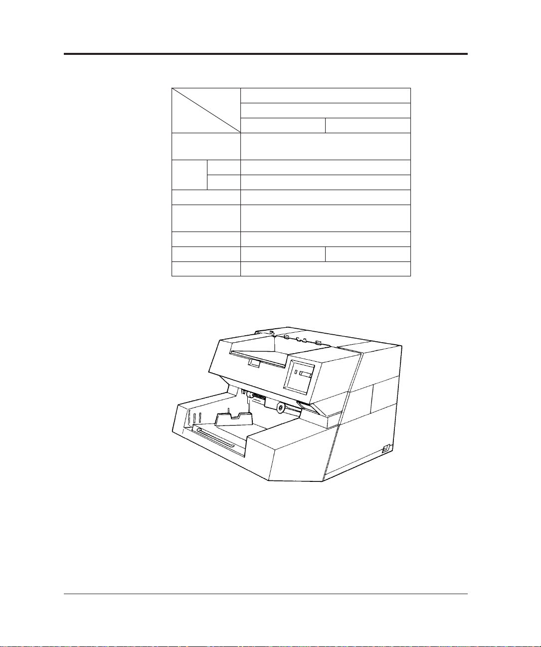
Table 1.2 Types of M3099GX
Type 1000 sheets hopper
with IPC2
Item 100V 200V
Maximum
document size
Scanning Simplex
Duplex
Hopper capacity 1000 sheets
Hight of
the Scanner
IPC2 (option) Installed
Input voltage 100V 200V
Appearance Figure 1.2
A3/Double letter
60 PPM (A4, 200dpi, portate)
50 PPM (A4, 200dpi, portrate)
530 mm
Figure 1.1 500 sheets hopper type
1-2 M3099GX/GH OEM Manual
Page 20
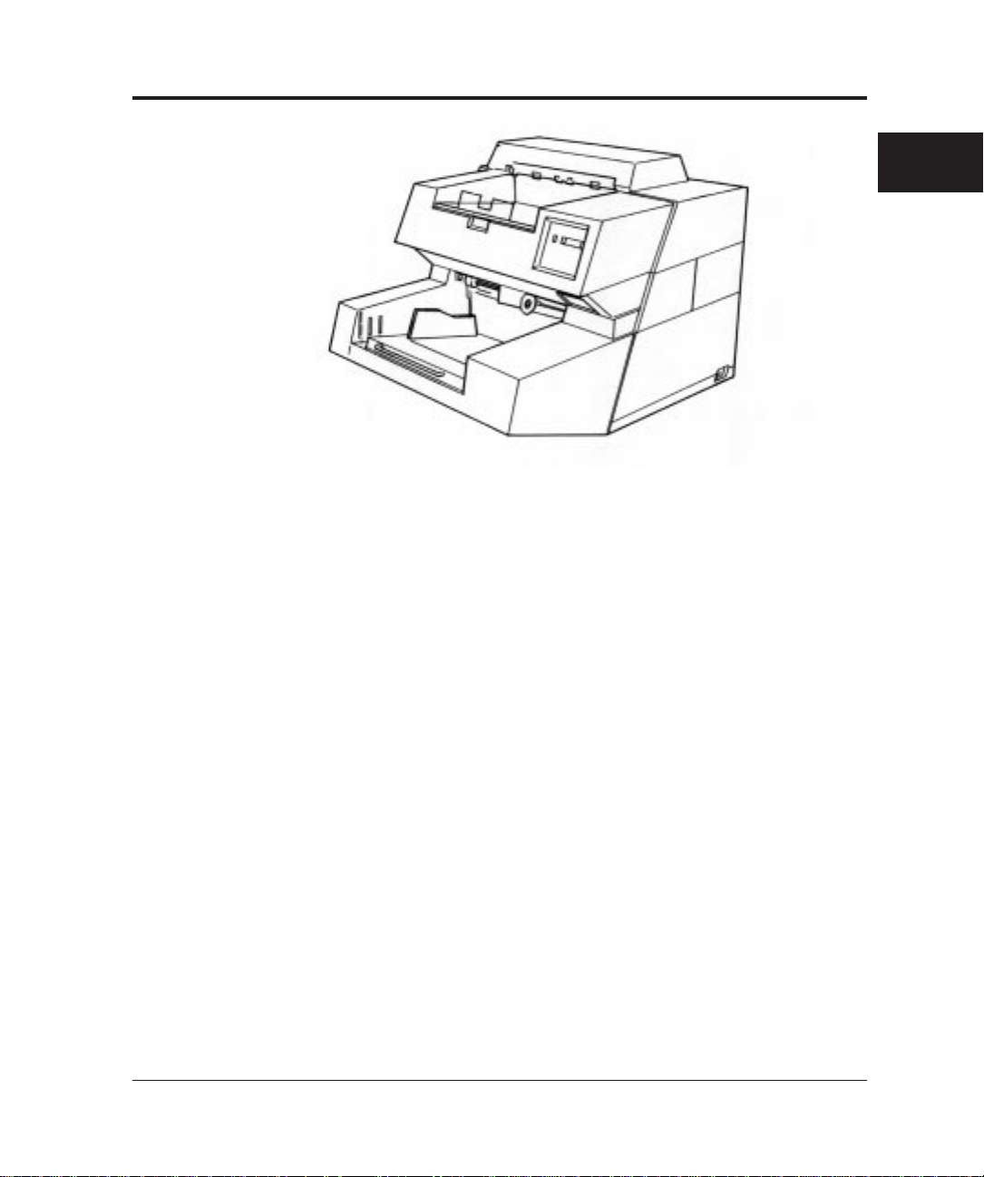
Figure 1.2 1000 sheets hopper type
OVERVIEW
M3099GX/GH OEM Manual 1-3
Page 21

Features
This scanner has the following features:
Duplex reading
Both sides of a document are read at the same time and their data
transferred serially.
Fast reading
This scanner can read documents at high speed: 80 sheets/min (A4,
200dpi) in the simplex reading mode and 60 sheets/min (A4,
200dpi) in the duplex reading mode by M3099GH.
Large-capacity hopper
Up to 1000 sheets (A4, 55 kg) can be loaded on the hopper by the
1000 sheets hopper type.
High-quality image
This scanner uses a compact optical system that provides sharper
focus. Furthermore, the use of new LSI chips produces finer images.
New image processing function
The error diffusion feature is provided as standard. Dithering or
error diffusion can be applied to those areas judged to be
photographs by automatic separation (image processing II option).
1-4 M3099GX/GH OEM Manual
Page 22
Configuration
This section provides configuration and components of the scanner.
Configuration of the scanner
This scanner can be divided into two major sections, mechanism and
control unit.
The mechanism unit consists of a hopper to load documents,
automatic document feeder, upper and lower transport units to
transport documents, a motor drive system, and an optical unit.
The control unit consists of an operator panel, a power supply, a
mechanism driver to drive and control the mechanism unit, an image
processing control, and an interface control.
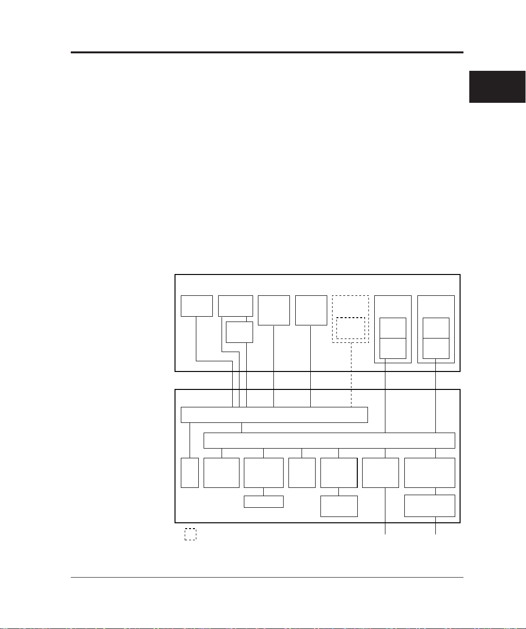
Figure 1.3 shows scanner configuration.
OVERVIEW
Mechanism unit
Transfer
system
Sensor Lamp,
(Front-side) (Back-side) (Back-side)
heater,
inverter
Sensor
board
Lamp,
heater,
inverter
Control unit
Mechanism driver
Motherboard
Fan Operator
panel
: Option
Back-side
reading
board
IPC-2 Extend
(Back-side)
IPC-2 Extend
(Front-side)
Figure 1.3 Scanner block diagram
Printer
Printer
driver
memory
board
memory
(Front-side)
Optical
system
CCD
driver
Video
circuit
Interface
board
SCSI-2 100/200VAC
Optical
system
CCD
driver
Video
circuit
Power supply
(5V, 12V)
Power supply
(24V)
M3099GX/GH OEM Manual 1-5
Page 23
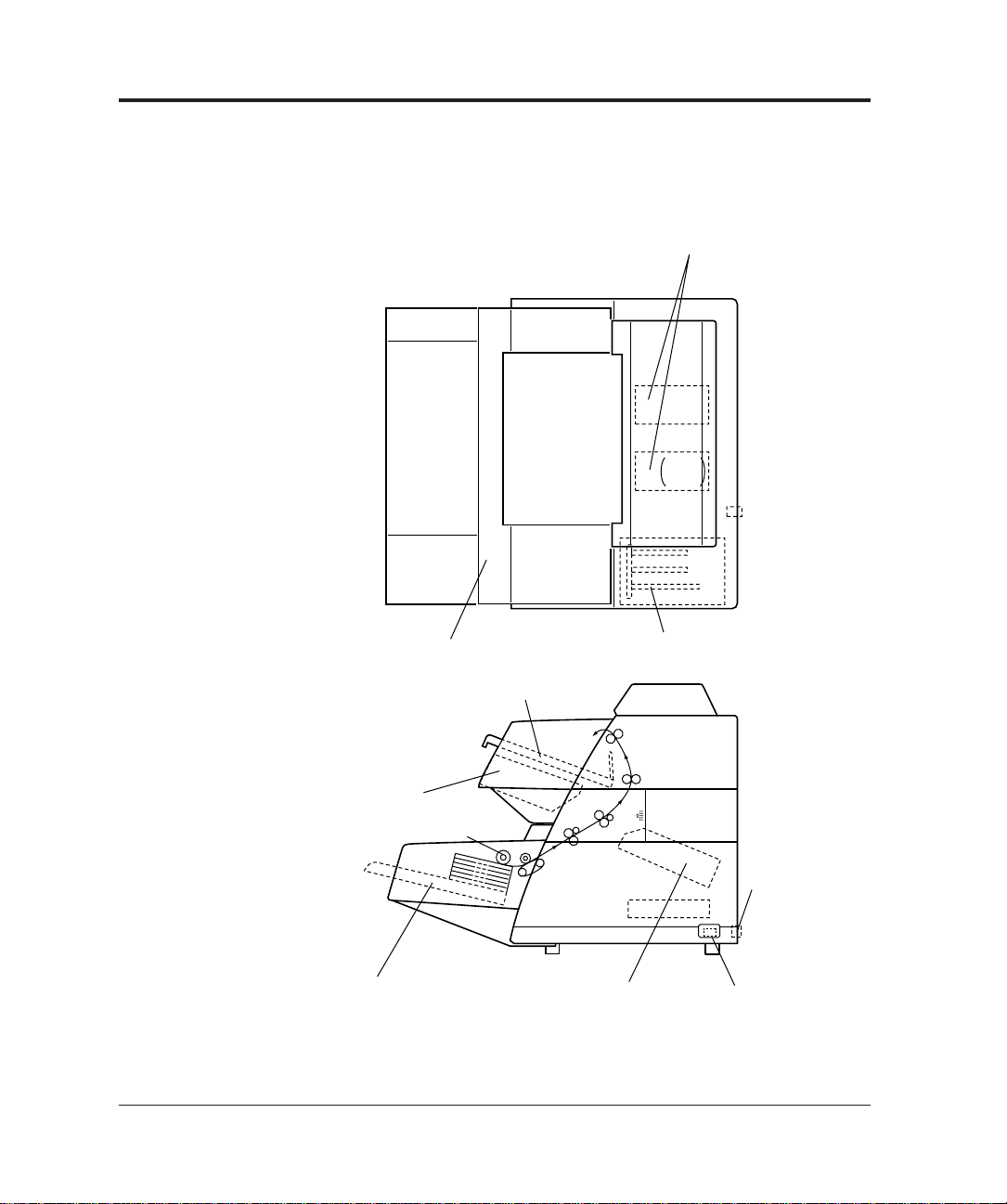
Arrangement of units
Power supply units
(+24V)
+5V
±12V
Control unitOperator panel
Stacker
Optical unit
(front-side)
Automatic document
feeder (ADF)
Hopper
Optical unit
(back-side)
Power switch
Power inlet
Figure 1.4 shows arrangement of these units.
1-6 M3099GX/GH OEM Manual
Figure 1.4 Arrangement of units
Page 24

Operation Overview
This section outlines the operations of the mechanism and control
units of the scanner.
Operation of the mechanism unit
The mechanism unit consists of two optical units (front and back
sides), a hopper and ADF, upper and lower transport units, a motor
drive system, and a stacker. Each optical unit consists of a CCD
image sensor, a lens, and mirrors. The hopper and ADF feeds
stacked documents and the upper and lower transport units transport
the documents. The motor drive system drives these units. The
stacker stores documents.
When the power is turned on, the lamps are lit and the scanner
waits until the light intensities of the lamps become stable. Once the
light intensities have become stable, the scanner is ready for a
command from the host machine.
A document is picked from the hopper and then ADF feeds a
document one by one. The document width is checked and
document top is detected.
The documents are counted, fed, and stacked on the stacker.
OVERVIEW
The lamps illuminate the document, and a lens focuses the images
on CCD for photoelectric conversion processing.
M3099GX/GH OEM Manual 1-7
Page 25
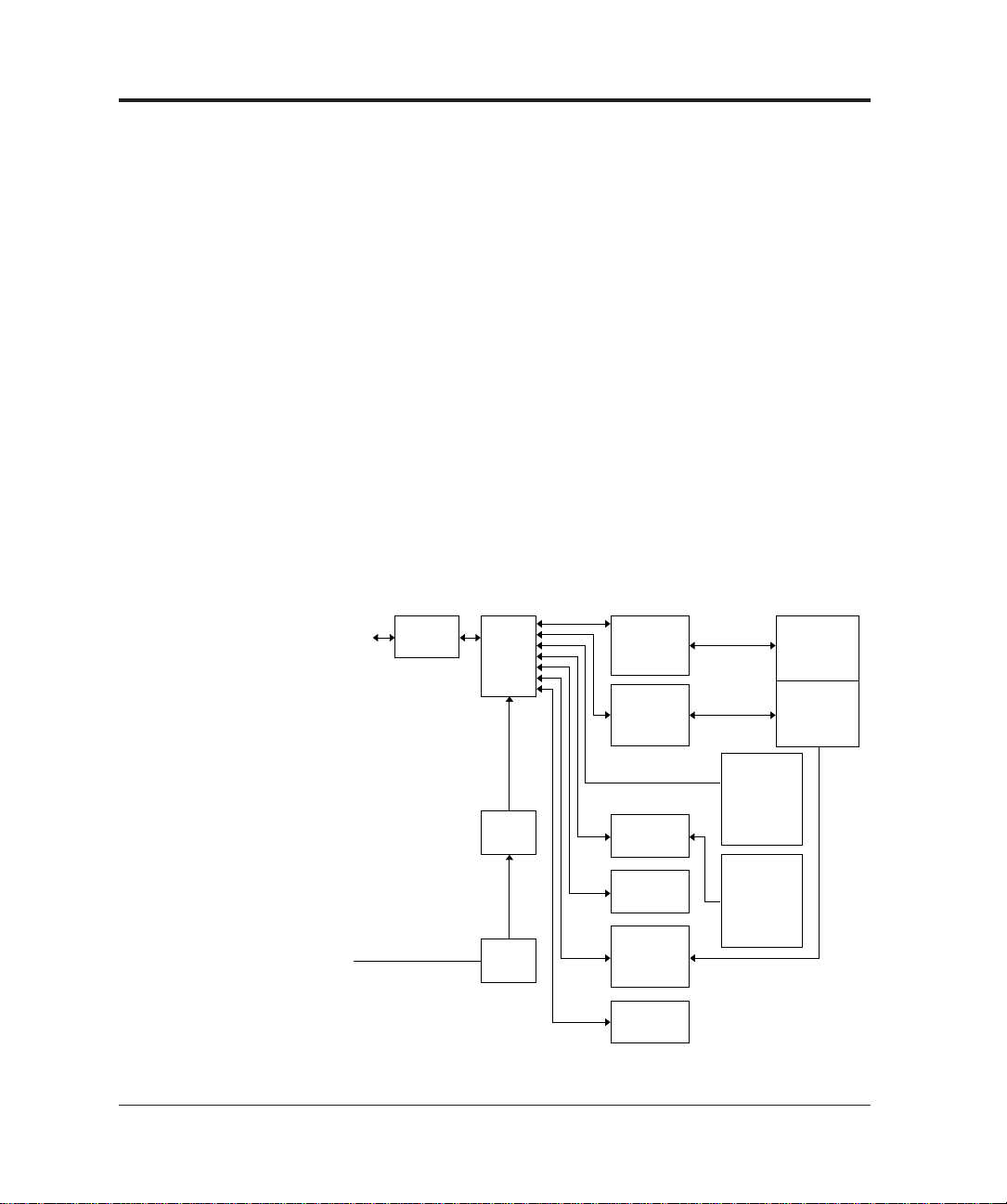
Operation of the control unit
The control unit consists of an operator panel, a power supply unit,
mechanism driver, an image processing control, and an interface
control.
This scanner has the following circuit configuration:
• Operator panel
• Control circuit (MPU)
• Video circuit (front-side/back-side)
• Interface circuit
• Duplex circuit (back-side)
• Motor driver circuit (including a stepper motor, a clutch driver)
• Power supply unit
• Image processing circuit (IPC II option)
• Memory board
Figure 1.5 shows control block diagram.
Host
machine
100 to 120 VAC
220 to 240 VAC
Interface
circuit
Control
circuit
(MPU )
Power
supply
Power
switch
Video
circuit
(front-side)
Video
circuit
(back-side)
Duplex
circuit
Memory
board
Motor
driver
circuit
Operator
panel
Mechanism
unit
ADF
MF
Image
processing
circuit II
(option)
(front-side)
Image
processing
circuit II
(option)
(back-side)
Figure 1.5 Control block diagram
1-8 M3099GX/GH OEM Manual
Page 26

Main control unit
This scanner is controlled by a 80C186 MPU. This scanner consists
of a ROM as a program area, internal registers, an external RAM as a
work area, gate arrays for the MPU peripheral and video circuits,
dither processing and γ conversion RAMs, and error diffusion.
Interface control
SCSI-2 interface
SCSI (small computer system interface) circuit consists of SPC
(MB86601A), VCEP (OTI95C71/20) and a glue ASIC. The scanned
image data are transferred to interface circuit as video interface. The
interface circuit converts internal video interface to SCSI interface via
compression, if required. SCSI interface transferes data 1.5MB/s in
Asynchronous transfer, 4.0MB/s in Synchronous transfer following to
SCSI-2 standard. The VCEP compresses the binary image data in
MH, MR, MMR algorithm defined by CCITT G3, G4. See Chapter
3 for details of SCSI interface.
Resolution
OVERVIEW
The basic resolution of this scanner is 200dpi. The resolution can be
changed to 240, 300, or 400dpi from the host computer or the
operator panel.
The resolution in the subscanning direction is achieved by changing
the document transport speed.
When the image processing circuit II (IPC II) option is installed, the
linear density is changed by setting the parameter to its internal circuit.
Video amplifier and driver section
This section consists of a CCD drive circuit, a video amplifier circuit,
a white-black level correction circuit, sensors, and also control circuits
for the stepping motor, heater, and lamps.
M3099GX/GH OEM Manual 1-9
Page 27

Image processing section
The IPC II option enables the following image processing functions:
• Automatic separation function (to read documents containing
characters and photographs)
• Inversion function
• Mirror image output function
• Outline extraction function
• Overlay function
• Smoothing, filtering, and noise removing
Power supplies
This scanner has two power supplies. Their output voltages are as
follows:
Power supply 1
• +5V: For logic circuits
• ±12V: For video amplifiers
Power supply 2
• 24V: For lamp, heater, and stepping motor drive
1-10 M3099GX/GH OEM Manual
Page 28

CHAPTER
2
General
SPECIFICATIONS
This chapter provides general, electrical, environmental, physical,
and option specifications.
Table 2.1 list general scanner specifications.
Table 2.1 General scanner specifications
Type
Item
Sensor
Scanning method
Document
size
Light source
Hopper/stacker
capacity
Gray scale (internal)
Output video
Scanning speed (A4,
200dpi, portrait)
Output density
Binarization and
halftone function
Interface
MAX.
MIN.
(64 g/m2)
Simplex
Duplex
ADF
216 × 356 mm (A4/Letter/Legal) 297 × 432 mm (A3/Double letter)
Standard: 400, 300, 240, 200dpi (Horizontal
scanning and vertical scanning are independent.)
If the image processing II (IPC2) is installed: 50 to
400 dpi (Horizontal scanning and vertical scanning
are independent.)
Standard: Fixed binarization, dither, error diffusion
method. If the image processing II (IPC2) is
installed: Automatic separation, image emphasis,
outline extraction, mirror image, inversion,
simplified DTC. Dynamic threshold, smoothing,
filtering, nois removing.
SCSI-2
M3099GH M3099GX
500 sheets hopper 1000 sheets hopper
CCD image sensor
(automatic document feeder)
76 × 63 mm (3" × 2.5")
Green fluorescent lamp
MAX. 500 MAX. 1000 MAX. 1000
sheets sheets sheets
Binary/Halftone (64 levels)
80 PPM 60 PPM
60 PPM 50 PPM
1000 sheets hopper
& MF
256 steps
(manual feeder)
SPECIFICATIONS
M3099GX/GH OEM Manual 2-1
Page 29

Electrical Specifications
Table 2.2 lists electrical specifications.
Table 2.2 Electrical specifications
Environmental Specifications
Item
Input power
Power consumption
Rush current
Momentary power failure
Leakage current
Dielectric strength
AC line noise
Heat capacity
Voltage
Phase
Frequency
Specification
100 to 120 VAC/220 to 240 VAC ±10%
Single-phase
50/60 Hz +2%, –4%
0.25 kVA or less
30 A or less
100%, 0.5 Hz
3.5 mA or less
DC 1.8 KV for one minute or more
(between FG and AC lines)
Voltage 1.2 KV pulse duration 5 µs
110 Kcal/H (440 BTU/H)
Table 2.3 lists environmental specifications.
Table 2.3 Environmental specifications
Item
Ambient
conditions
Shock
Stability
Acoustic noise
ESD
Device status
Temperature
Humidity
Specification
Operating
5 to 35°C
20 to 80%
(no condensation)
0.2 G less
5° or less
59 dBA or less
(ISO 7779)
8 KV or more
Not operating
–20 to 60°C
8 to 95%
(no condensation)
0.4 G or less
10° or less
50 dBA or less
(ISO 7779)
2-2 M3099GX/GH OEM Manual
Page 30
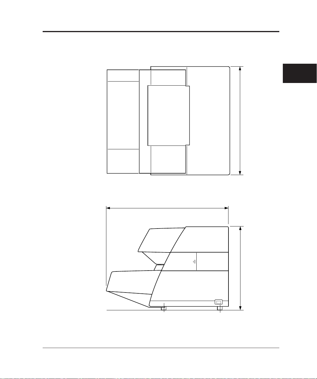
Physical Specifications
Figure 2.1 to Figure 2.2 show the scanner dimensions, Figure 2.3
shows scanner service areas. Table 2.4 lists physical specifications.
SPECIFICATIONS
610
680
470
(Unit: mm)
Figure 2.1 Dimensions of 500 sheets hopper type
M3099GX/GH OEM Manual 2-3
Page 31

680
610
530
(Unit: mm)
Figure 2.2 Dimensions of 1000 sheets hopper type
2-4 M3099GX/GH OEM Manual
Page 32

Table 2.4 Physical specifications
Type
Item
Dimensions
Weight
500 sheets hopper type 1000 sheets hopper type
Width
Depth
Height
610 mm 610 mm
680 mm 680 mm
470 mm 530 mm
55kg 65kg
SPECIFICATIONS
600680600
Scanner
F
200 610 600
1,390
1,860
F: Front
(Unit: mm)
Figure 2.3 Service areas
M3099GX/GH OEM Manual 2-5
Page 33

Option Specifications
Table 2.5 lists the scanner option specifications.
Table 2.5 Option specifications
Item
Endorser
Specification
CA01023-D004
Detail
Ink-jet
back-side print
max. 20 characters
Remark
2-6 M3099GX/GH OEM Manual
Page 34

CHAPTER
3
INTERFACE
INTERFACE
The M3099G image scanner provides SCSI-2(Small Computer
System Interface-2) interface. The SCSI-2 is a 8 bit-parallel interface
standardized by ANSI(American National Standard Institute).
This chapter provides an overview of the SCSI and interface
specification of this scanner. For detail information, refer to ANSI
SCSI standard document.
Definitions
• SCSI device: A host adapter or a target controller that can be
attached to the SCSI bus.
• Initiator: An SCSI device that requests an I/O process to be
performed by another SCSI device(a target).
• Target: An SCSI device that performes an operation
requested by an initiator.
• Logical unit: A physical or virtual peripheral device addressable
through a target.
Scope
This interface specification is following X3T9.2 draft proposal
revision 10c. refering JBMS(Japan Business Machine Standard).
System configuration
This scanner operates under the multi-initiator, multi-target
environment. An initiator function is not provided. This scanner
incorporates an integrated target and logical unit (image scanner).
SCSI ID: 0 to 7(changeable), default 5.
Logical Unit Number (LUN): 000b(fixed).
M3099GX/GH OEM Manual 3-1
Page 35

Bus phases
All phases are supported
Commands
• INQUIRY
• OBJECT POSITION
• MODE SELECT(6)
• MODE SENSE(6)
• READ
• RELEASE UNIT
• REQUEST SENSE
• RESERVE UNIT
• SCAN
• SEND
• SEND DIAGNOSTIC
• SET WINDOW
• TEST UNIT READY
• ENDORSER (ENDORSER option is required)
Statuses
• BUSY
• CHECK CONDITION
• GOOD
• RESERVEATION CONFLICT
Messages
• ABORT
• BUS DEVICE RESET
• COMMAND COMPLETE
• DISCONNECT
• IDENTIFY
• INITIATOR DETECTED ERROR
• MESSAGE PARITY ERROR
• MESSAGE REJECT
3-2 M3099GX/GH OEM Manual
Page 36

• NO OPERATION
• RESTORE POINTERS
• SAVE DATA POINTER
• SYNCHRONOUS DATA TRANSFER REQUEST
Physical Specifications
Connection
SCSI devices are daisy-chaned together using a common 50conductor ‘A’ cable and, optionally, a 68-conductor ‘B’ cable. Both
ends of each cable are terminated. All signals are common between
all SCSI devices on the ‘A’ cable. In systems that employ the wide
SCSI option, wide SCSI devices additionally connect to the ‘B’ cable.
Various width SCSI devices may be mixed. This scanner supports ‘A’
cable.
Note: Use of ‘B’ cable is not recommended because of ANSI draft
proposal indicates this definition is removed in a future
version of the SCSI.
SCSI device SCSI device SCSI device SCSI device
TERMINATOR
Figure 3.1 SCSI device connection
TERMINATOR
INTERFACE
M3099GX/GH OEM Manual 3-3
Page 37

Physical specification
Table 3.1 SCSI physical specification
Item
Driver/receiver
Connector
Cable
Signal
level
Connector pin assignments for
signal lines
Max. cable length
Characteristic impedance
Cable type
Stub length
Terminator
Driver/receiver
Output characteristics:
Low-level output voltage
High-level output voltage
Input characteristics :
Low level input voltage
High level input voltage
Low level input current
High level input current
Minimum input hysteresis
Specification
Single Ended
50 Contact Shielded Low Density
6 m
90␣ Ω to 140 Ω
25 signal twisted pair
≤ 0.1 m (from mainline)
See Figure. 3.2
Open collector or three states driver
0.0 to 0.5 volts dc at 48mA sinking
(signal assertion)
2.5 to 5.25 volts dc (signal
negation)
0.0 to 0.8 volts dc
2.0 to 5.25 volts dc
–0.4 to 0.0mA at Vi=0.5 volts dc
0.0 to 0.1mA at Vi=2.7 volts dc
0.2 volts dc
See Table 3.2
3-4 M3099GX/GH OEM Manual
Page 38

Termination
Low dropout voltage regulater
Imax ≥ 600mA
Vout = 2.85V
(See Note 1)
Vin Vout
Vadj
R1
R2
C2 C3
+
R3
Component Description
R1
R2
R3-R20
C1
C2
C3
121 Ω, 1%, 0.25W
154 Ω, 1%, 0.25W
110 Ω, 1%
10 µF Alum.15V or 4.7 µF Tant. 15V
150 µF Alum.10V or 22 µF Tant. 10V (ESR at 120 Hz < 4)
0.1 µF Ceramic 25V
+
R20
NOTES
1 The voltage regulator shown is an adjustable type with Vref=1.25V.
R1 and R2 were selected to provide approximately 10mA Iquiescent.
The voltage regulator Vdropout shall be 1.25V or less at Imax.
2 Alternative values that provide lower performance at somewhat
lower cost use Vout 1%; R3−R20=100 Ω,2%
All signals not defined as RESERVED, GROUND, or TERMPWR
shall be terminated at both ends of the cable. The Implementor may
choose one of the following two methods to terminate each end (see
ANSI SCSI-2 ANSI SCSI-2 5.4 Electrical description):
Single-ended alternative (a) [Passive terminator]
TERMINATOR POWER
INTERFACE
M3099GX/GH OEM Manual 3-5
–SIGNAL
220 Ω
330 Ω
GROUND
Figure 3.2 Alternative 1 termination for Single Ended Devices
Single-ended alternative (b) [Active terminator]
Figure 3.3 Alternative 2 termination for Single Ended Devices
The first termination method above is the same as in SCSI-1. The
second termination method is recommended for better signal quality.
Page 39

Connector pin assignments
Table 3.2 Single Ended Contact Assignment - ‘A’ Cable
Signal
Name
GROUND
GROUND
GROUND
GROUND
GROUND
GROUND
GROUND
GROUND
GROUND
GROUND
GROUND
GROUND
OPEN
GROUND
GROUND
GROUND
GROUND
GROUND
GROUND
GROUND
GROUND
GROUND
GROUND
GROUND
GROUND
Connector
Contact
Number Set 2
1
2
3
4
5
6
7
8
9
10
11
12
13
14
15
16
17
18
19
20
21
22
23
24
25
Cable
Connector
Number
1
3
5
7
9
11
13
15
17
19
21
23
25
27
29
31
33
35
37
39
41
43
45
47
49
Connector
Contact
Number Set 2
2
4
6
8
10
12
14
16
18
20
22
24
26
28
30
32
34
36
38
40
42
44
46
48
50
26
27
28
29
30
31
32
33
34
35
36
37
38
39
40
41
42
43
44
45
46
47
48
49
50
Signal Name
-DB(0)
-DB(1)
-DB(2)
-DB(3)
-DB(4)
-DB(5)
-DB(6)
-DB(7)
-DB(P)
GROUND
GROUND
RESERVED
TERMPWR
RESERVED
GROUND
-ATN
GROUND
-BSY
-ACK
-RST
-MSG
-SEL
-C/D
-REQ
-I/O
3-6 M3099GX/GH OEM Manual
Page 40

Note: The minus sign next to a signal indicates active low.
The lines labeled RESERVED in the ‘A’ cable contact
assignment tables shall be connected to ground in the bus
terminator assemblies or in the end devices on the SCSI cable.
The RESERVED lines should be open in the other SCSI
devices, but may be connected to ground. The RESERVED
lines in this scanner are opened.
SCSI Bus (See ANSI SCSI-2 4.5)
Communication on the SCSI bus is allowed between only two SCSI
devices at any given time. There is a maximum of eight SCSI devices.
Each SCSI device has an SCSI ID bit assigned as shown in Figure
3.4.
DB(0)
DB(1)
DB(7)
SCSI ID
Figure 3.4 DATA BUS
ID=7
DB(6)
ID=6
DB(5)
ID=5
DB(4)
ID=4
DB(3)
ID=3
DB(2)
ID=2
ID=1
ID=0
INTERFACE
M3099GX/GH OEM Manual 3-7
Page 41

SCSI Bus Signals (See ANSI SCSI-2 4.6)
Table 3.3 SCSI Bus Signals
Signal
BSY(BUSY)
SEL(SELECT)
C/D
(CONTROL/DATA)
MSG(MESSAGE)
REQ(REQUEST)
ACK
(ACKNOWLEDGE)
ATN(ATTENTION)
RST(RESET)
DB(7-0,P)
(DATA BUS)
Description
An "OR tied" signal that indicates that the bus is
being used.
An "OR tied" signal used by an initiator to select
a target or by a target to reselect an initiator.
A signal driven by a target that controls the
direction of data movement on the DATA BUS
with respect to an initiator. True indicates input
to the initiator. This signal is also used to
distiguish between SELECTION and
RESELECTION phase.
A signal driven by a target during the MESSAGE
phase.
A signal driven by a target on the A cable to
indicate a request for an ACK information
transfer handshake.
A signal driven by an initiator on the A cable to
indicate an acknowledgement for a REQ
information transfer handshake.
A signal driven by an initiator to indicate the
ATTENTION condition.
An "OR tied" signal that indicates the RESET
condition.
Eight data bit signals, plus a parity bit signal that
from a DATA BUS. DB(7) is most significant bit
and has the highest priority during the
ATTENTION phase. Bit number, significance
and priority decrese downward to DB(0). A data
bit is defined as one when the signal value is true
and is defined as zero when the signal value is
false. Data parity DB(P) shall be odd. Parity is
undefined during the ARBITRATION phase.
3-8 M3099GX/GH OEM Manual
Page 42

Signal Values
Signals may assure true or false values. These are two methods of
driving these signals. In both cases, the signal shall be actively driven
true, or asserted. In the case of OR tied drivers, the driver does not
drive the signal to the false state, rather the bias circuitry of the bus
terminators pulls the signal false whenever it is released by the drivers
at every SCSI device. If any driver is asserted, then the signal is true.
In the case of non OR tied drivers, the signal may be actively driven
false. In this standard, whenever the term negated is used, it means
that the signal may be actively driven false, or may be simply released
(in which case the bias circuitry pulls it false), at the option of the
implementor.
Signal Source
Table 3.4. indicates which type of SCSI device is allowed to source
each signal. No attempt is made to show if the source is driving
asserted driving negated, or is passive. All SCSI device drivers that are
not active sources be in the passive state. The RST signal may be
asserted by any SCSI device at any time.
INTERFACE
M3099GX/GH OEM Manual 3-9
Page 43

Table 3.4 Signal Source
C/D, I/O,
MSG,
Bus Phase
BUS FREE
ARBITRATION
SELECTION
RESELCTION
COMMAND
DATA IN
DATA OUT
STATUS
MESSAGE IN
MESSAGE OUT
All: The signal shall be driven by all SCSI devices that are actively
arbitrating.
S ID: A unique data bit (the SCSI ID) shall be driven by each SCSI
device that is actively arbitrating; the other seven data bits shall be
released (i.e., not driven) by this SCSI device. The parity bit
(DB(P)) may be released or driven to the true state, but shall never
be driven to the false state during this phase.
The signal shall be driven by the initiator, target or both, as
specified in the SELECTION phase and RESELECTION phase.
Init: If driven, this signal shall be driven only by the active initiator.
None: The signal shall be released; that is, not be driven by any SCSI
device. The bias circuitry of the bus terminators pulls the signal to
the false state.
Win: The signal shall be driven by the one SCSI device that wins
arbitration.
Targ: If the signal is driven, it shall be driven only by the active target.
BSY
None
All
I&T
I&T
Targ
Targ
Targ
Targ
Targ
Targ
SEL
None
Win
Init
Targ
None
None
None
None
None
None
REQ
None
None
None
Targ
Targ
Targ
Targ
Targ
Targ
Targ
ACK,
ATN
None
None
Init
Init
Init
Init
Init
Init
Init
Init
DB(7,0)
DB(P)
None
S ID
Init
Targ
Init
Targ
Init
Targ
Targ
Init
3-10 M3099GX/GH OEM Manual
Page 44

SCSI Bus Timing
Unless otherwise indicated, the delay time measurements for each
SCSI device, shown in Table 3.5., shall be calculated from signal
conditions existing at that SCSI device’s own SCSI bus connection.
Thus, these measurements (except cable skew delay) can be made
without considering delays in the cable. The timing characteristics of
each signal are described in the following paragraphs.
Table 3.5 SCSI Bus Timing Values
INTERFACE
Timing Description
Arbitration Delay
Assertion Period
Bus Clear Delay
Bus Free Delay
Bus Set Delay
Bus Settle Delay
Cable Skew Delay
Data Release Delay
Deskew Delay
Disconnection Delay
Hold Time
Negation Period
Power-On to Selection Time
Reset to Selection Time
Reset Hold Time
Selection Abort Time
Selection Time-out Delay
Transfer Period
Timing Values
2.4 µs
90 ns
800 ns
800 ns
1.8 µs
400 ns
10 ns
400 ns
45 ns
200 µs
45 ns
90 ns
10 s recommended
25 µs
200 µs
200 µs
250 ms recommended
set during an SDTR message
M3099GX/GH OEM Manual 3-11
Page 45

Arbitration Delay
The minimum time an SCSI device shall wait from asserting BSY for
arbitration until the DATA BUS can be examined to see if
arbitration has been won. There is no maximum time.
Assertion period
The minimum time that a target shall assert REQ (or REQB) while
using synchronous data transfers. Also, the minimum time that an
initiator shall assert ACK (or ACKB) while using synchronous data
transfers. REQB and ACKB timings only apply to optional wide data
transfers.
Bus Clear Delay
The maximum time for an SCSI device to stop driving all bus signals
after:
• The BUS FREE phase is detected.
• SEL is received from another SCSI device during the
ARBITRATION phase.
• The transition of RST to true.
For the first condition above, the maximum time for an SCSI device
to clear the bus is 1200 nanoseconds from BSY and SEL first
becoming both false. If an SCSI device requires more than a bus
settle delay to detect BUS FREE phase, it shall clear the bus within a
bus clear delay minus the excess time.
Bus Free Delay
The minimum time that an SCSI device shall wait from its detection
of the BUS FREE phase until its assertion of BSY when going to the
ARBITRATION phase.
Bus Set Delay
The maximum time for an SCSI device to assert BSY and its SCSI
ID bit the DATA BUS after it detects BUS FREE phase for the
purpose of entering the ARBITRATION phase.
3-12 M3099GX/GH OEM Manual
Page 46

Bus Settle Delay
The minimum time for wait for the bus to settle after changing
certain control signals as called out in the protocol definitions.
Cable Skew Delay
The maximum difference in propergation time allowed between any
two SCSI bus signals measured between any two SCSI devices.
Data Release Delay
The maximum time for an initiator to release the DATA BUS signals
following the transition of the I/O signals from false to true.
Deskew Delay
The minimum time required for deskew of certain signals.
Disconnection Delay
The minimum time that a target shall wait after releasing BSY before
participating in an ARBITRATION phase when honoring a
DISCONNECT message from the initiator.
Hold Time
The minimum time added between the assertion of REQ(or REQB)
or ACK(or ACKB) and the changing of the data lines to provide
hold time in the initiator or target while using synchronous data
transfers. REQB and ACKB timings only apply to optional wide data
transfers.
INTERFACE
Negation Period
The minimum time that a target shall negate REQ (or REQB) while
using synchronous data transfers. Also, the minimum time that an
initiator shall negate ACK (or ACKB) while using synchronous data
transfers. REQB and ACKB timings only apply to optional wide data
transfers.
M3099GX/GH OEM Manual 3-13
Page 47

Power-On to Selection Time
The recommended maximum time from power application until an
SCSI target is able to respond with appropriate status and sense data
to the TEST UNIT READY, INQUIRY, and REQUEST SENSE
commands.
Reset to Selection Time
The recommended maximum time after a hard RESET condition
until an SCSI target is able to respond with appropriate status and
sense data to the TEST UNIT READY, INQUIRY, and REQUEST
SENSE commands.
Reset Hold Time
The minimum time for which RST is asserted. There is no
maximum time.
Selection Abort Time
The maximum time that a target (or initiator) shall take from its
most recent detection of being selected (or reselected) until asserting
a BSY response. This time-out is required to ensure that a target (or
initiator) does not assert BSY after a SELECTION (or
RESELECTION) phase has been aborted. This is not the selection
time-out period; see ANSI SCSI-2 6.1.3.1. and ANSI SCSI-2
6.1.4.2. for a complete description.
Selection Time-out Delay
The minimum time that a SCSI device should wait for a BSY
response during the SELECTION or RESELECTION phase before
starting the time-out procedure. Note that this is only a
recommended time period.
3-14 M3099GX/GH OEM Manual
Page 48

Transfer Period
The Transfer Period specifies the minimum time allowed between
the leading edges of successive REQ pulses and of successive ACK
pulses while using synchronous data transfers. (See ANSI SCSI-2
6.1.5.2 and ANSI SCSI-2 6.6.21.)
INTERFACE
SCSI Bus Phases
The SCSI architecture includes eight distinct phases:
a) BUS FREE phase
b) ARBITRATION phase
c) SELECTION phase
d) RESELECTION phase
e) COMMAND phase
f) DATA phase
g) STATUS phase
h) MESSAGE phase
The SCSI bus can never be in more than one phase at any given
time. In the following descriptions signals that are not mentioned
shall not be asserted.
These phases are collectively termed
the information transfer phase.
BUS FREE Phase (See ANSI SCSI-2 6.1.1 for details)
The BUS FREE phase indicates that there is no current I/O process
and that the SCSI bus is available for a connection.
SCSI devices shall detect the BUS FREE phase after the SEL and
BSY signals are both false for at least a bus settle delay.
SCSI devices shall release all SCSI bus signals within a bus clear delay
after the BSY and SEL signals become continuously false for a bus
settle delay. If an SCSI device requires more than a bus settle delay to
detect the BUS FREE phase then it shall release all SCSI bus signals
within a bus clear delay minus the excess time to detect the BUS
FREE phase. The total time to clear the SCSI bus shall not exceed a
bus settle delay plus a bus clear delay.
M3099GX/GH OEM Manual 3-15
Page 49

If an initiator detects the release of the BSY signal by the target at
any other time, the target is indicating an error condition to the
initiator. The target may perform this transition to the BUS FREE
phase independent of the state of the ATN signal. The initiator shall
manage this condition as an unsuccessful I/O process termination.
The target terminates the I/O process by clearing all pending data
and status information for the affected nexus. The target may
optionally prepare sense data that may be retrieved by a REQUEST
SENSE command.
ARBITRATION Phase
The ARBITRATION phase allows one SCSI device to gain control
of the SCSI so that it can initiate or resume an I/O process.
The procedure for an SCSI device to obtain control of the SCSI bus
is as follows:
a) The SCSI device shall first wait for the BUS FREE phase to
occur. The BUS FREE phase detected whenever both the BSY
and SEL signals are simultaneously and continuously false for a
minimum of a bus settle delay.
b) The SCSI device shall wait a minimum of a bus free after
detection of the BUS FREE phase (i.e. after the BSY and SEL
signals are both false for a bus settle delay) before driving any
signal
c) 3)Following the bus free delay in Step(b), the SCSI device may
arbitrate for the SCSI bus by asserting both the BSY signal and its
own SCSI ID, however the SCSI device shall not arbitrate (i.e.
assert the BSY signal and its SCSI ID) if more than a bus settle
delay has passed since the BUS FREE phase was last observed.
3-16 M3099GX/GH OEM Manual
Page 50

d) After waiting at least an arbitration delay (measured from its
assertion of the BSY signal) the SCSI device shall examine the
DATA BUS. If a higher priority SCSI ID bit is true on the
DATA BUS (DB(7) is the highest), then the SCSI devices has
lost the arbitration and the SCSI device may release its signals
and return to Step(a). If no higher priority SCSI ID bit is true on
the DATA BUS, then the SCSI device has won the arbitration
and it shall assert the SEL signal. Any SCSI device other than the
winner has lost the arbitration and shall release the BSY signal
and its SCSI ID bit within a bus clear delay after the SEL signal
becomes true. An SCSI device that loses arbitration may return to
Step(a).
e) The SCSI device that wins arbitration shall wait at least a bus
clear delay plus a bus settle delay after asserting the SEL signal
before changing any signals.
SELECTION Phase
The SELECTION phase allows an initiator to select a target for the
purpose of initiating some target function (e.g., READ or WRITE
command). During the SELECTION phase the I/O signal is
negated so that this phase can be distinguished from the
RESELECTION phase.
INTERFACE
The SCSI device that won the arbitration has both the BSY and SEL
signals asserted and has delayed at least a bus clear delay plus a bus
settle delay before ending the ARBITRATION phase. The SCSI
device that won the arbitration becomes an initator by not asserting
the I/O signal.
The initiator shall set the DATA BUS to a value which is the OR of
its SCSI ID bit and the target’s SCSI ID bit and it shall assert the
ATN signal (indicating that a MESSAGE OUT phase is to follow
the SELECTION phase). The initiator shall the wait at least two
deskew delays and release the BSY signal. The initiator shall then
wait at least a bus settle delay before looking for a response from the
target.
The target shall not respond to selection if bad parity is detected.
Also, if more than two SCSI ID bits are on the DATA BUS, the
target shall not respond to selection.
M3099GX/GH OEM Manual 3-17
Page 51

No less than two deskew delays after the initiator detects the BSY
signal is true, it shall release the SEL signal and may change the
DATA BUS. The target shall wait unitl the SEL signal is false before
asserting the REQ signal to enter an information transfer phase. (See
ANSI SCSI-2 6.1.3.1 SELECTION Time-out Procedure)
RESELECTION Phase
RESELCTION is an optional phase that allows a target to reconnect
to an initiator for the purpose of continuing some operation that was
previously started by the initiator but was suspended by the
target(i.e., the target disconnected by allowing a BUS FREE phase to
occur before the operation was completed).
RESELECTION
Upon completing the ARBITRATION phase, the winning SCSI
device has both the BSY and SEL signals asserted and has delayed at
least a bus clear delay plus a bus settle delay. The winning SCSI
device becomes a target by asserting the I/O signal. The winning
SCSI device shall also set the DATA BUS to a value that is the
logical OR of its SCSI ID bit and the initiator’s SCSI ID bit. The
target shall wait at least two deskew delays and release the BSY signal.
The target shall wait at least a bus settledelay before looking for a
response from the initiator.
The initiator shall determine that it is reselected when the SEL and
I/O signals and its SCSI ID bit are true and the BSY signal is false
for at least a bus settle delay. The reselected initiator may examine
the DATA BUS in order to determine the SCSI ID of the reselecting
target. The reselected initiator shall then assert the BSY signal within
a selection abort time of its most recent detection of being reselected;
this is required for correct operation of the time-out procedure. The
initiator shall not respond to a RESELECTION phase if bad parity
is detected.
Also, the initiator shall not respond to a RESELECTION phase if
other than two SCSI ID bits are on the DATA BUS.
3-18 M3099GX/GH OEM Manual
Page 52

After the target detects the BSY signal is true, it shall also assert the
BSY signal and wait at least two deskew delays and then release the
SEL signal. The target may then change the I/O signal and the
DATA BUS. After the reselected initiator detects the SEL signal is
false, it shall release the BSY signal. The target shall continue
asserting the BSY signal until it relinquished the SCSI bus. (See
ANSI SCSI-2 6.1.4.2. RESELECTION Time-out Procedure)
Information Transfer Phases
NOTE: The COMMAND, DATA, STATUS, and MESSAGE
phases are all grouped together as the information transfer phases
because they are all used to transfer data or control information via
the DATA BUS. The actual content of the information is beyond
the scope of this section.
The C/D, I/O, and MSG signals are used to distinguish between the
different information transfer phases(see Table 3.6). The target
drives these three signals and therefore controls all changes from one
phase to another. The initiator can request a MESSAGE OUT phase
by asserting the ATN signal, while the target can cause the BUS
FREE phase by releasing the MSG, C/D, I/O, and BSY signals.
The information transfer phases use one or more REQ/ACK
handshakes to control the information transfer. Each REQ/ACK
handshake allows the transfer of one byte of information. During the
information transfer phases the BSY signal shall remain true and the
SEL signal shall remain false. Additionally, during the inforamtion
transfer phases, the target shall continuously envelope the REQ/ACK
handshake(s) with the C/D, I/O, and MSG signals in such a manner
that these control signals are valid for a bus settle delay before the
assertion of the REQ signal of the first handshake and remain valid
until after the negation of the ACK signal at the end of the
handshake of the last transfer of the phase.
INTERFACE
M3099GX/GH OEM Manual 3-19
Page 53

Table 3.6 Information Transfer Phases
Signal
MSG
C/D
0
0
0
0
0
1
0
1
1
0
1
0
1
1
1
1
Key: 0 = False, 1 = True, * = Reserved for future standardization
Phase Name
I/O
DATA OUT
0
DATA IN
1
COMMAND
0
STATUS
1
*
0
*
1
MESSAGE OUT
0
MESSAGE IN
1
Direction of Transfer
Initiator to target
Initiator from target
Initiator to target
Initiator from target
Initiator to target
Initiator to target
Comment
Data
Phase
Message
Phase
Asynchronous Information Transfer
The target shall control the direction of information transfer by
means of the I/O signal. When the I/O signal is true, information
shall be transferred from the target to the initiator. When the I/O
signal is false, information shall be transferred from the initiator to
the target. If the I/O signal is true (transfer to the initiator), the
target shall first drive the DB(7-0,P) signals to their desired values,
delay at least one deskew delay plus a cable skew delay, then assert
the REQ signal. The DB(7-0,P) signals shall remain valid until the
ACK signal is true at the target. The initiator shall read the DB(70,P) signals after the REQ signal is true, then indicate its acceptance
of the data by asserting the ACK signal. When the ACK signal
becomes true at the target, the target may change or release the
DB(7-0,P) signals and shall negate the REQ signal. After the REQ
signal is false the initiator shall then negate the ACK signal. After the
ACK signal is false the target may continue the transfer by dividing
the DB(7-0,P) signals and asserting the REQ signal, as described
above.
3-20 M3099GX/GH OEM Manual
Page 54

If the I/O signal is false (transfer to the target) the target shall request
information by asserting the REQ signal. The initiator shall drive the
DB(7-0,P) signals to their desired values, delay at least one deskew
delay plus a cable skew delay and assert the ACK signal. The initiator
shall continue to drive the DB(7-0,P) signals until the REQ signal is
false. When the ACK becomes true at the initiator, the initiator may
change or release the DB(7-0,P) signals and shall negate the ACK
signal. After the ACK signal is false the target may continue the
transfer by asserting the REQ signal, as described above.
Synchronous Data Transfer
Synchronous data transfer is optional and is only used data phases. It
shall be used in a data phase if a synchronous data transfer agreement
has been established (see SYCHRONOUS DATA TRANSFER
REQUEST Message). The agreement specifies the REQ/ACK offset
and the minimum transfer period.
The REQ/ACK offset specifies the maximum number of REQ pulses
that can be sent by the target in advance of the number of ACK
pulses received from initiator, establishing a pacing mechanism. If
the number of REQ pulses exceeds the number of ACK pulses by the
REQ/ACK offset, the target shall not assert the REQ signal until
after the leading edge of the next ACK pulse is received. A
requirement for successful completion of the data phase is that the
number of ACK and REQ pulses be equal.
INTERFACE
The target shall assert the REQ signal for a minimum of an assertion
period. The target shall then wait at least the greater of a transfer
period from the last transition of the REQ signal to true or a
minimum of a negation period from the last transition of the ACK
signal to false before asserting the ACK signal.
The initiator shall send one pulse on the ACK signal for each REQ
pulse received. The ACK signal may be asserted as soon as the
leading edge of the corresponding REQ pulse has been received. The
Initiator shall assert the ACK signal for a minimum of an assertion
period. The initiator shall wait at least the greater of transfer period
from the last transition of the ACK signal to true or for a minimum
of a negation period from the last transition of the ACK signal to
false before asserting the ACK signal.
M3099GX/GH OEM Manual 3-21
Page 55

If the I/O signal is true (transfer to the initiator), the target shall first
drive the DB(7-0,P) signals to their desired values, wait at least one
deskew delay plus one cable skew delay, then assert the REQ signals.
The DB(7-0,P) signals shall be held valid for a minimum of one
deskew delay plus one cable skew delay plus one hold time after the
assertion of the REQ signal. The target shall assert the REQ signal
for a minimum of an assertion period. The target may then negate
the REQ signals within one hold time of the transition of the REQ
signal to true. The initiator shall then respond with an ACK pulse.
If the I/O signal is false (transfer to the target), the initiator shall
tranfer one byte for each REQ pulse received. After receiving the
leading edge of a REQ pulse, the initiator shall first drive the DB(70,P) signals to their desired values, delay at least one deskew delay
plus one cable skew delay, then assert the ACK signal. The initiator
shall hold the DB(7-0,P) signals valid for at least one deskew delay
plus one cable skew delay plus one hold time after the assertion of
the ACK signal. The initiator shall assert the ACK signal for a
minimum of an assertion period. The initiator may then negate the
ACK signal and may one hold time of the transition of the ACK
signal to true.
COMMAND Phase
The COMMAND phase allows the target to request command
information from the initiator.
The target shall assert the C/D signal and negate the I/O and MSG
signals during the REQ/ACK handshake(s) of this phase.
Data Phase
The data phase is a term that encompasses both the DATA IN phase
and the DATA OUT phase.
3-22 M3099GX/GH OEM Manual
Page 56

DATA IN Phase
The DATA IN phase allows the target to request that data be sent to
the initiator from the target.
The target shall assert the I/O signal and negate the C/D and MSG
signals during the REQ/ACK handshake(s) of this phase.
DATA OUT Phase
The DATA OUT phase allows the target to request that data be sent
from the target to the initiator.
The target shall negate the C/D, I/O, and MSG signals during the
REQ/ACK handshake of this phase.
STATUS Phase
The STATUS phase allows the target to request that status
information be sent from the target to the initiator.
The target shall assert the C/D and I/O signals and negate the MSG
signal during the REQ/ACK handshake of this phase.
INTERFACE
Message Phase
The message phase is a term that references either a MESSAGE IN,
or a MESSAGE OUT phase. Multiple messages may be sent during
either phase. The first byte transferred in either of these phases shall
be either a single-byte message or the first byte of a multiple-byte
message. Multiple-byte messages shall be wholly contained within a
single message phase.
MESSAGE IN Phase
The MESSAGE IN phase allows the target to request that message(s)
be sent to the initiator from the target.
The target shall assert the C/D, I/O, and MSG signals during the
REQ/ACK handshake(s) of this phase.
M3099GX/GH OEM Manual 3-23
Page 57

MESSAGE OUT Phase (See ANSI SCSI-2 6.1.9.2 for details)
The MESSAGE OUT phase allows the target to request that
message(s) be sent from the initiator to the target. The target invokes
this phase in response to the attention condition created by the
initiator.
The target shall assent the C/D and MSG signals and negate the I/O
signal during the REQ/ACK handshake(s) of this phase. The target
shall handshake byte(s) in this phase until the ATN signal is negated,
except when rejecting a message.
If the target receives all of the message byte(s) successfully (i.e., no
parity errors), it shall indicate that it does not wish to retry by
changing to any information transfer phase other than the
MESSAGE OUT phase and transfer at least one byte. The target
may also indicate that it has successfully received the message byte(s)
by changing to the BUS FREE phase (e.g., ABORT or BUS
DEVICE RESET messages).
SCSI Bus Conditions
The SCSI bus has two asynchronous conditions; the attention
condtion. These conditions cause the SCSI device to perform ceratin
actions and alter the phase sequence.
Attention Condition
The attention condition allows an initiator to inform a target that
the initiator has a message ready. The target may get this message by
performing a MESSAGE OUT phase.
The initiator creates the attention condition by asserting ATN at any
time except during the ARBITRATION or BUS FREE phases.
The initiator shall negate the ATN signal at least two deskew delays
before asserting the ACK signal while transferring the last byte
transferred in a bus phase for the attention condition to be honored
before transition to a new bus phase. Asserting the ATN signal later
might not be honored until a later bus phase and then may not result
in the expected action. See ANSI SCSI-2 6.2.1 for details.
3-24 M3099GX/GH OEM Manual
Page 58

Reset Condition
The reset condition is used to immediately clear all SCSI devices
from the bus. This condition shall take precedence over all other
phases and condtions. Any SCSI device may create the reset
condition by asserting the RST signal for a minimum of a reset hold
time.
All SCSI devices shall release all SCSI bus signals (except the RST
signal) within a bus clear delay of the transition of the RST signal to
true. The BUS FREE phase always the reset condition.
The effect of the reset condition on I/O processes which have not
completed, SCSI device reservations, and SCSI device operation
modes is determined by whether the SCSI device has implemented
the hard reset alternative or the soft reset alternative (one of which
shall be implemented) as defined in ANSI SCSI-2 6.2.2.1 and
6.2.2.2. The hard and soft reset alternative is implemented is
provided in the SftRe bit of the INQUIRY data. This scanner
supports Hard Reset alternative as below.
Hard Reset Alternative:
1) Clear all I/O process including queued I/O process.
2) Release all SCSI device reservations.
3) Return any SCSI device operation modes to their appropriate
initial conditions, similar to those conditions that would be
found after a normal power-on reset. MODE SELECT
conditions shall be restored to their last saved values if saved
values have been established. MODE SELECT conditions for
which no values have been save shall be returned to their default
values.
4) Unit attention condition shall be set.
INTERFACE
Note: I/O process queuing in (1) and parameter saving in (3) are
not supported in this scanner.
M3099GX/GH OEM Manual 3-25
Page 59

Reset or
protocol
error
BUS FREE
SELECTION
ARBITRATION
RESELECTION
DATA IN or
DATA OUT
COMMAND
MESSAGE OUT
STATUS
MESSAGE IN
SCSI Bus Phases Sequences
The order in which phases are used on the SCSI bus follows a
prescribed sequence.
The reset condition can abort any phase and is always followed by
the BUS FREE phase. Also any other phase can be followed by the
BUS FREE phase but many such instances are error conditions.
The additional allowable sequences shall be as shown in Figure 3.5.
The normal progression is from the BUS FREE phase to
ARBITRATION, from ARBITRATION to SELECTION or
RESELECTION, and from SELECTION or RESELECTION to
one or more of the information tranfer phases (COMMAND,
DATA, STATUS, or MESSAGE). The final information transfer
phase is normally the MESSAGE IN phase where a
DISCONNECT, or COMMAND COMPLETE message is
transferred, followed by the BUS FREE phase.
3-26 M3099GX/GH OEM Manual
Figure 3.5 Phase Sequence
Page 60

Commands (See ANSI SCSI-2 7)
A command is communicated by sending a command descriptor
block to the target. For several commands, the command descriptor
block is accompanied by a list of parameters sent during the DATA
OUT phase. The command descriptor block always has an operation
code as its first byte and a control byte as its last byte.
Reserved (See ANSI SCSI-2 7.1.1)
Reserved bits, fields, bytes, and code values are set aside for future
standardization. Their use and interpretation may be specified by
future extensions to ANSI SCSI standard. A reserved bit, field, or
byte shall be set to zero, or in accordance with a future extension to
this standard. A target that receives a reserved bit, field, or byte that
is not zero or receives a reserved code value shall terminate the
command with CHECK CONDITION status and the sense key
shall be set to ILLEGAL REQUEST.
Logical Unit Number
The logical unit number is defined in the IDENTIFY message. The
target shall ignore the logical unit number specified within the
command descriptor block if an IDENTIFY message was received.
This scanner supports Logical Unit Number 000b only. Followings
shows target’s response to selection of invalid logical unit.
• In response to an INQUIRY command, the target shall return the
INQUIRY data with the peripheral qualifier set to the value
required.
• In response to any other command except REQUEST SENSE, the
target shall terminate the command with CHECK CONDITION
status.
• In response to an REQUEST SENSE command, the target shall
return sense data. The sense key shall be set to ILLEGAL
REQUEST and the additional sense code shall be set to
LOGICAL UNIT NOT SUPPORTED.
INTERFACE
M3099GX/GH OEM Manual 3-27
Page 61

Transfer Length
The transfer length field specifies the amount of data to be
transfered, usually number of blocks. The block length is this scanner
is 1byte. In command that use multiple bytes for the transfer length,
a transfer length of zero indicates that no data transfer shall take
place. A value of one or greater indicates the number if blocks that
shall be transferred.
Allocation Length
The allocation length field specifies the maximum number of bytes
that an initiator has a allocated for returned data. An allocation
length of zero indicates that no data shall be transferred. This
condition shall not be considered as an error. The target shall
terminate the DATA IN phase when allocation length bytes have
been transferred or when all available data have been transferred to
the initiator, whichever is less. The allocation length is used to limit
the maximum amount of data(e.g. sense data, mode data, etc)
returned to initiator.
Control field
The control field is the last byte of every command descriptor block.
The control field is defined in ANSI SCSI-2 7.2.7. In this scanner,
this field is not used. Any field in this byte is regarded as Reserved.
3-28 M3099GX/GH OEM Manual
Page 62

Table 3.7 Operation Code Types
Command
RESERVE UNIT
RELEASE UNIT
INQUIRY
REQUEST SENSE
SEND DIAGNOSTIC
ENDORSER
TEST UNIT READY
SET WINDOW
SEND
OBJECT POSITION
SCAN
READ
MODE SELECT(6)
MODE SENSE(6)
Operation
Code(hex)
16
17
12
03
1D
C1
00
24
2A
31
18
28
15
1A
Description
Reserve a logical unit
Release a previously reserved logical
unit
Requests information regarding
parameters of target and its attached
peripheral device(s).
Requests the target transfer sense
data to the initiator
Request the target to perform
diagnostic operations on itself
Start/Stop endorser function
Check if the logical unit is ready
Specify windows within the
scanning range of the device.
Transfers data from initiator to
target
Provids positioning functions (ADF
Feed in/out)
Requests the target begin a scan
operation
Requests the target transfer data to
the initiator
Specify logical unit, peripheral
device parameters from the initiator
to the target
Report parameters from the target to
the initiatot
INTERFACE
M3099GX/GH OEM Manual 3-29
Page 63

RESERVE UNIT Command
The RESERVE UNIT command (Table 3.8) is used to reserve
logical unit for the exclusive use of the requesting initiator to another
specified SCSI device.
Table 3.8 RESERVE UNIT Command
Bit
7 6 5 3 2 1 0
Byte
0
1
Logical Unit Number 3rdPty Third Party Device ID
2
3
4
5
The RESERVE UNIT and RELEASE UNIT commands provide the
basic mechanism for contention resolution in multiple-initiator
systems.
This command requests that the entire logical unit be reserved for
the exclusive use of the initiator until the reservation is superseded by
another valid RESERVE UNIT command from the initiator that
made the reservation or until released by a BUS DEVICE RESET
message from any initiator, by a hard reset condition, or by a power
on cycle. The reservation shall not be granted if the logical unit is
reserved by another initiator. It shall be permissible for an initiator to
reserved a logical unit that is currently reserved by that initiator.
4
Operation Code (16h)
Reserved
Reserved
Reserved
Reserved
Control
If the logical unit is reserved for another initiator, the target shall
return RESERVATION CONFLICT status.
3rdPty: 0b (Reserved)
Third Party Device ID: 000b (Reserved)
3-30 M3099GX/GH OEM Manual
Page 64

Superseding Reservations
An initiator that currntly has a logical unit reserved may modify the
current reservation by issuing another RESERVE UNIT command
to the same logical unit. The superseding reservation shall release the
current reservation if the superseding reservation request is granted.
If the superseding resrvation cannot be granted because of conflicts
with a previous reservation (other than the current reservation), then
the target shall return RESERVATION CONFLICT status.
See ANSI SCSI-2 9.2.10.2 for details.
RELEASE UNIT Command
The RELEASE UNIT command (Table 3.9) is used to release
previously reserved logical units for the requesting initiator to
another specified SCSI device.
Table 3.9 RELEASE UNIT Command
Bit
Byte
7 6 5 3 2 1 0
0
1
Logical Unit Number 3rdPty Third Party Device ID
2
3
4
5
4
Operation Code (17h)
Reserved
Reserved
Reserved
Reserved
Control
INTERFACE
The RESERVE UNIT and RELEASE UNIT commands provide the
basic mechanism for contention resolution in multiple-initiator
systems.
If a valid reservation exists for the I_T_L nexus, the target shall
release the reservation and return GOOD status.
M3099GX/GH OEM Manual 3-31
Page 65

A reservation may only be released by the initiator that made it. It is
not an error to attempt to release reservation that is currently valid or
is held by another initiator. In this case, the target shall return
GOOD status without altering any other reservation.
3rdPty: 0b (Reserved)
Third Party Device ID: 000b (Reserved)
TEST UNIT READY Command
The TEST UNIT READY command (Table 3.10) provides a means
to check if the logical unit is ready. This is not a request for a selftest.
If the logical unit would accept an appropriate command without
returning CHECK CONDITION status, this command shall return
a GOOD status. If the logical unit cannot become operational the
target shall return CHECK CONDITION status with a sense key of
NOT READY.
Table 3.10 TEST UNIT READY Command
Bit
Byte
7 6 5 3 2 1 0
0
1
Logical Unit Number Reserved
2
3
4
5
4
Operation Code (00h)
Reserved
Reserved
Reserved
Control
INQUIRY Command (See ANSI SCSI-2 7.2.5)
The INQUIRY command (Table 3.11) requests that information
regarding parameters of the target and its attached peripheral
device(s) be sent to the initiator. An option allows the inititor to
request additional information about the target or logical unit (See
ANSI SCSI-2 7.2.5.2 Vital Product Data).
3-32 M3099GX/GH OEM Manual
Page 66

Table 3.11 INQUIRY Command
Bit
Byte
7 6 5 3 2 1 0
0
1
Logical Unit Number Reserved EVPD
2
3
4
5
4
Operation Code (12h)
Page Code
Reserved
Allocation Length
Control
EVPD (Enable Vital Product Data):
This bit of one specifies that the target shall return the optional vital
product data specified by the page code field. If the target does not
support vital product data and this bit is set to one, the target shall
return CHECK CONDITION status with the sense key set to
ILLEGAL REQUEST and an additional sense code of INVALID
FIELD IN CDB.
This bit of zero specifies that the target shall return the standard
INQUIRY data. If the page code field not zero, the target shall
return CHECK CONDITION status with the sense key set to
ILLEGAL REQUEST and an additional sense code of INVALID
FIELD IN CDB.
INTERFACE
Page Code:
This field specifies which page of vital product data information the
target shall return (see ANSI SCSI-2 7.3.4). The supported vital
product data in this scanner is Page Code F0h.
The INQUIRY command shall return CHECK CONDITION
status only when the target cannot return the requested INQUIRY
data.
M3099GX/GH OEM Manual 3-33
Page 67

If an INQUIRY command is received from an initiator with a
pending unit attention condition (i.e., before the target reports
CHECK CONDITION status), the target shall perform the
INQUIRY command and shall not clear the unit attention
condition.
Standard INQUIRY Data (See ANSI SCSI-2 7.2.5.1)
This standard INQUIRY data (Table 3.12) contains 36 required
bytes, followed by a variable number of vendor-specific parameters.
Bytes 56 through 95, if returned, are reserved for future
standardization.
3-34 M3099GX/GH OEM Manual
Page 68

Table 3.12 Standard INQUIRY Data Format
Bit
7 6 5 3 2 1 04
Byte
0
Peripheral Qualifier Peripheral Device Type
1
RMB Device-Type Modifier
2
ISO Version ECMA Version
3
AENC Reserved
4
5
6
7
8
– – –
RelAdr
(MSB)
– – –
WBus32 WBus16
Additional Length (n-4)
Reserved
Reserved
Vendor Identification
15
16
(MSB)
– –␣ –
– – –
Product Identification
31
32
(MSB)
– – –
– – –
Product Revision Level
35
36
–␣ –␣ –
Vendor Specific
55
56
–␣ –␣ –
Reserved
95
Vendor-Specific Parameters
96
–␣ –␣ –
Vendor Specific
n
Linked
ANSI Approved Version
Reserved
CmdQue
SftReSync
– – –
(LSB)
– – –
(LSB)
– – –
(LSB)
INTERFACE
M3099GX/GH OEM Manual 3-35
Page 69

The peripheral qualifier and peripheral device type fields identify the
device currently connected to the logical unit. If the target is not
capable of supporting a device on this logical unit, this field shall be
set to 7Fh (peripheral qualifier set to 011b and peripheral device type
set to 1Fh).
Peripheral Qualifier: 000b(Connected)
Peripheral Device Type: 06h(Scanner Device)
RMB(Removable Medium Bit): 0b(not supported).
Device Type Modifier: 0000000b(not supported)
ISO Version: 00b(does not claim compliance
with ISO)
ECMA Version: 000b(does not claim compliance
with ECMA)
ANSI Approved Version: 2h(SCSI-2, if approved)
AENC(Asynchronous Event Notification Capability):
0b(Reserved)
TrmIOP(Terminate I/O Process):
0b(not supported. see ANSI SCSI-
2 5.6.22)
Response Data Format: 2h(INQUIRY Data Format is
defined in SCSI-2)
Additional Length: 91(n=95)
This field shall specify the length in bytes of the parameters. If the
allocation length of the command descriptor block is too small to
transfer all of the parameters, the additional length shall not be
adjusted to reflect the truncation.
RelAdr(Relative Addressing): 0b(not supported)
Wbus32(Wide Bus 32): 0b(not supported)
Wbus16(Wide Bus 16): 0b(not supported)
Sync(Synchronous Transfer): 1b(synchronous transfer supported)
Linked(Linked Command): 0b(not supported)
CmdQue(Command Queuing): 0b(not supported)
SftRe(Soft Reset): 0b(Hard Reset)
Vendor Identification: “FUJITSU “
3-36 M3099GX/GH OEM Manual
Page 70

Product Identification: (M3099GH)
“M3099GHdm ” default (Duplex, CMP2 equivalent)
“M3099GHdem ” with ENDORSER option
“M3099GHdim ” with IPC2 option
“M3099GHdeim ” with ENDORSER, IPC2 options
Product Identification: (M3099GX)
“M3099Gdm ” default (Duplex, CMP2 equivalent)
“M3099Gdem ” with ENDORSER option
“M3099Gdim ” with IPC2 option
“M3099Gdeim ” with ENDORSER, IPC2 options
Product Identification: (M3096G)
“M3096Gm ” default
“M3096Gim ” with IPC2 option
Product Revision Level: “01 ”(Black and White Binary)
Vital Product Data
JBMS(Japanese Business Machines Standard) is defining standard
Vital Product Data. (See JBMS-40-1990) Fujitsu Scanners also
support this data by adding Fujitsu original extention. JBMS-401990 uses 30 Bytes as standard VPD to describe specification and
functions.This data is obtained by setting EVPD bit to 1 and Page
Code to F0h in INQUIRY command.
If Product Identification has changed to M3096G or M3099G in
Off-line SETUP mode following data are returned. The ‘d’ which
indicates Duplex, and ‘e’ which indicates ENDORSER are not
returned. See Chapter 4 Operator panel.
INTERFACE
M3099GX/GH OEM Manual 3-37
Page 71

Table 3.13 Standard VPD Page Format
Bit
7 6 5 3 2 1 04
Byte
10
11
12
13
14
15
16
17
18
19
20
23
24
27
28
29
30
to
0
1
2
3
4
5
(MSB)
6
7
(MSB)
8
9
(MSB)
(MSB)
(MSB)
(MSB)
(MSB)
(MSB)
(MSB)
n
Res Step X Res Step Y
Peripheral Device Type
Page Number(F0h)
J Version
Reserved
Page Length (m-5)
Basic X Resolution
Basic Y Resolution
Maximum X Resolution
Maximum Y Resolution
Minimum X Resolution
Minimum Y Resolution
Standard Resolution
Window Width
Window Length
Function
Reserved
Vendor Unique Parameter Byte(s)
(LSB)
(LSB)
(LSB)
(LSB)
(LSB)
(LSB)
(LSB)
(LSB)
(LSB)
3-38 M3099GX/GH OEM Manual
Page 72

Peripheral Device: 06h(Image Scanner)
Page Number: F0h(Page Code)
J Version: 02h(JBMS 0.2)
Page Length: 95(m=100)
Basic X Resolution: 200(200dpi)
Basic Y Resolution: 200(200dpi)
Res Step X: 00h(Variable Resolution)
Res Step Y: 00h(Variable Resolution)
Maximum X Resolution: 400(400dpi with/without IPC2)
Maximum Y Resolution: 400(400dpi with/without IPC2)
Minimum X Resolution: 200(without IPC2)/50(with IPC2)
Minimum Y Resolution: 200(without IPC2)/50(with IPC2)
Standard Resolution: 01D0h(without IPC2)/FFF0h(with IPC2)
This field indicates available resolution bit is set as as described in
Table 3.14. This is applied to only for main-scan direction.
Table 3.14 Standard Resolution (unit:Pixel/Inch)
Bit
Byte
17
18
7
60
240
6
75
300
5
100
320
4
120
400
3
150
480
2
160
600
1
180
800
0
200
1200
INTERFACE
Window Width: 00000980h(2432 dot) for M3099GX
000006C0h(1728dot) for M3099GH
Window Length: 00000D80h(3456 dot)
Window Width and Window Length fields are maximum width and
length those are available by the scanner. The units are pixels
counted by the basic resolution.
Function: 00000110b
Function field specifies functions supported by the scanner. Each bit
is set to 1 corresponding to Table 3.15.
M3099GX/GH OEM Manual 3-39
Page 73

Table 3.15 Function
Bit
Description
Bit 0
Bit 1
Bit 2
Bit 3
Bit 4
Bit 5
Bit 6
Bit 7
Data Over Flow
Scanners that will cause data over flow sets this bit to 1. Image
scanners that will not cause data over flow set this bit to 0.
Support of Start Switch is not specified.
Binary (Black and White)
Scanners support Black and White set this bit to 1. Scanners do
not support Black and White set this bit to 0.
Dither/Halftone
Scanners support Dither/Halftone set this bit to 1. Scanners do
not support Dither/Halftone set this bit to 0.
Grayscale
Scanners support Grayscale set this bit to 1. Scanners do not
support Grayscale set this bit to 0.
Steps of gray is not specified.
Reserved (Bit 4 to 7 are Reserved in JBMS)
Binary (RGB Color)
Scanners support (RGB Color) set this bit to 1. Scanners do not
support (RGB Color) set this bit to 0.
Dither/Halftone(RGB Color)
Scanners support Dither/Halftone (RGB Color) set this bit to 1.
Scanners do not support Dither/Halftone (RGB Color)set this
bit to 0.
Grayscale(RGB Color)
Scanners support Grayscale(RGB Color) set this bit to 1.
Scanners do not support Grayscale(RGB Color) set this bit to 0.
Steps of gray is not specified.
*) Data Over Flow means when receipt of data by the initiator is
too slow, data buffer of image scanner is filled and data is not
guranteed.
Fujitsu further defines own Vital Product Data using Vendor
Specific field of JBMS. This extended Vital Product Data is used by
Device Driver to confirm which functions are supported. Current
defined data is totally 100 bytes but it will be expanded by future
functions.
3-40 M3099GX/GH OEM Manual
Page 74

Table 3.16 Standard VPD Page Extended Format
Bit
7 6 5 3 2 1 04
Byte
30
31
32
(MSB)
Reserved
Reserved
Physical Function
33
34
(MSB)
Buffering Capability
37
38
(MSB)
Implemented Standard Command
41
42
Implemented Vendor Specific Command
49
50
Implemented Vendor Unique Parameter
81
82
Image Control Function
87
88
Image Processing Function
89
90
Compression Function
91
92
Endorser Function
93
94
Barcode Function
97
95
Reserved
100
INTERFACE
(LSB)
(LSB)
(LSB)
M3099GX/GH OEM Manual 3-41
Page 75

Physical Function: 10010010 00001000b(without
ENDORSER)
10011010 00001000b(with
ENDORSER)
Physical Function field of each bit indicates Physical variated
functions.
Table 3.17 Physical Function
Byte
32
33
Bit
1XXXXXXXb
X1XXXXXXb
XX1XXXXXb
XXX1XXXXb
XXXX1XXXb
XXXXX1XXb
XXXXXX1Xb
XXXXXXX1b
0000nnnnb
Description
Automatic Document Feeder
Flatbed
Tranceparency
Duplex
Endorser
Barcode
Operator Panel
Reserved
Bits of ADC
Buffering Capability: 0080 0000h(8M Bytes)
Buffering Capability field indicates that interface buffering capability
in bytes.
Implemented Standard Command:
0000 0000 0000 0000 1110 1101 1011
1111b = 0000EDBFh
Implemented Standard Command field of each bit indicates
supported SCSI command as Table 3.18.
3-42 M3099GX/GH OEM Manual
Page 76

Table 3.18 Implemented Standard Command
Bit
Command
0
TEST UNIT READY
1
REQUEST SENSE
2
INQUIRY
3
MODE SELECT(6)
4
RESERVE UNIT
5
RELEASE UNIT
6
COPY
7
MODE SENSE(6)
8
SCAN
9
RECEIVE DIAGNOSTIC RESULTS
10
SEND DIAGNOSTIC
11
SET WINDOW
12
GET WINDOW
13
READ
14
SEND
15
OBJECT POSITION
16
GET DATA BUFFER STATUS
17
COMPARE
18
COPY AND VERIFY
19
WRITE BUFFER
20
READ BUFFER
21
CHANGE DEFINITION
22
LOG SELECT
23
LOG SENSE
24
MODE SELECT(10)
25
MODE SENSE(10)
26
Reserved
27
Reserved
28
Reserved
29
Reserved
30
Reserved
31
Reserved
Code
00h
03h
12h
15h
16h
17h
18h
1Ah
1Bh
1Ch
1Dh
24h
25h
28h
2Ah
31h
34h
39h
3Ah
3Bh
3Ch
40h
4Ch
4Dh
55h
5Ah
M
M
M
O
M
M
O
O
O
O
M
M
O
M
O
O
O
O
O
O
O
O
O
O
O
O
INTERFACE
M3099GX/GH OEM Manual 3-43
Page 77

Implemented Vendor Specific Command:
CXh = 0000h, DXh = 0000h, EXh = 0000h, FXh = 0000h
(without ENDORSER)
CXh = 0002h, DXh = 0000h, EXh = 0000h, FXh = 0000h
(with ENDORSER)
Implemented Vendor Specific Command field indicates vendor
specific command implemented by the scanner. This field consists of
4 sets of 2 bytes structure as Table 3.19. Each bit position in these
fields indicates lower 4 bits of the command code.
Implemented Vendor Specific Command field is subdivided to CXh,
DXh, EXh, FXh as Table 3.20.
Table 3.19 2 bytes structure
Bit
7
Byte
0
bit 15
1
bit 7
Table 3.20 Implemented Vendor Specific Command
6
bit 14
bit 6
5
bit 13
bit 5
4
bit 12
bit 4
3
bit 11
bit 3
2
bit 10
bit 2
1
bit 9
bit 1
0
bit 8
bit 0
Bytes
42, 43
44, 45
46, 47
48, 49
Description
Vendor Specific Command field - CXh
Vendor Specific Command field - DXh
Vendor Specific Command field - EXh
Vendor Specific Command field - FXh
Table 3.21 Implemented Vendor Specific Command
Field&Bit
CXh 0
DXh
EXh
FXh
Command
SET SUBWINDOW
1
ENDORSER
Code
C0h
C1h
V
V
3-44 M3099GX/GH OEM Manual
Page 78

Vendor Unique Parameter: See Table 3.22
Vendor Unique Parameter field indicates supported Vendor Unique
Parameter pages defined in SET WINDOW command. Vendor
Unique Parameter field consists of 16 sets of 2 bytes structure as
Table 3.22.Vendor Unique Parameter field are subdivided to fields
0Xh to FXh.
Table 3.22 Vendor Unique Parameter
INTERFACE
Bytes
50, 51
52, 53
54, 55
56, 57
58, 59
60, 61
62, 63
64, 65
66, 67
68, 69
70, 71
72, 73
74, 75
76, 77
78, 79
80, 81
Description
Vendor Unique Parameter - 0Xh
Vendor Unique Parameter - 1Xh
Vendor Unique Parameter - 2Xh
Vendor Unique Parameter - 3Xh
Vendor Unique Parameter - 4Xh
Vendor Unique Parameter - 5Xh
Vendor Unique Parameter - 6Xh
Vendor Unique Parameter - 7Xh
Vendor Unique Parameter - 8Xh
Vendor Unique Parameter - 9Xh
Vendor Unique Parameter - AXh
Vendor Unique Parameter - BXh
Vendor Unique Parameter - CXh
Vendor Unique Parameter - DXh
Vendor Unique Parameter - EXh
Vendor Unique Parameter - FXh
Value
0001h
0000h
0000h
0000h
0000h
0000h
0000h
0000h
0000h
0000h
0000h
0000h
0000h
0000h
0000h
0000h
Image Control Function field indicates supplementary information
on SET WINDOW arameter. Image Control Function field is
subdivided to Brightness Steps, Threshold Steps, Contrast Steps,
Number of resident Dither, Number of registrable Dither, Number
of resident Gamma Function, Number of registrable Gamma
Function as Table 3.23.
M3099GX/GH OEM Manual 3-45
Page 79

Brightness Step: FFh(255 steps)
Brightness Step field indicates available steps of the Brightness. If
zero is pecified, Brightness Control is not supported.
Threshold Step: FFh(255 steps)
Threshold Step field indicates available steps of the Threshold. If
zero is pecified, Threshold Control is not supported.
Contrast Step: FFh(255 steps)
Contrast Step field indicates available steps of the Contrast. If zero is
pecified, Contrast Control is not supported.
Number of Resident Dither: 0100xxxxb(4 patterns)
Number of Resident Dither field indicates number of resident
Dither patterns in 4 bits. If zero is specified no dither pattern is
available.
Number of Registerable Dither: xxxx1000b(8 patterns)
Number of Registerable Dither field indicates registrable dither
patterns in 4 bits. If zero is specified no dither pattern is registrable.
Number of Resident Gamma Function: 0100xxxxb(4 patterns)
Number of Resident Gamma Function field indicates number of
resident gamma functions in 4 bits. If zero is specified no gamma
function is available.
Number of Registrable Gamma Function: xxxx1000b(8 patterns)
Number of Registrable Gamma Function field indicates registrable
gamma functions in 4 bits. If zero is specified no gamma function is
registrable.
3-46 M3099GX/GH OEM Manual
Page 80

Table 3.23 Image Control Function
Byte
82
83
84
85
86
87
Bit
nnnnnnnnb
nnnnnnnnb
nnnnnnnnb
00000000b
nnnnXXXXb
XXXXnnnnb
nnnnXXXXb
XXXXnnnnb
Description
Brightness Steps
Threshold Steps
Contrast Steps
Reserved
Number of resident Dither
Number of registrable Dither
Number of resident Gamma Function
Number of registrable Gamma Function
Image Processing Function:10000001 01000000b(without IPC2)
11111111 01000000b(with IPC2)
Image Processing function field of each bit indicates supported
Image Processing function.
Table 3.24 Image Processing Function
Byte
88
89
Bit
1XXXXXXXb
X1XXXXXXb
XX1XXXXXb
XXX1XXXXb
XXXX1XXXb
XXXXX1XXb
XXXXXX1Xb
XXXXXXX1b
1XXXXXXXb
X1XXXXXXb
XX1XXXXXb
XXX1XXXXb
XXXX1XXXb
XXXXX1XXb
XXXXXX1Xb
XXXXXXX1b
Description
Reverse Image Format
Dynamic Threshold Circuit
Simplified DTC
Outline Extract
Image Emphasis
Automatic Separation
Mirror Image
White Level Follower
Subwindow
Error Diffusion
Reserved
Reserved
Reserved
Reserved
Reserved
Reserved
INTERFACE
M3099GX/GH OEM Manual 3-47
Page 81

Compression Function: 11100000 00000000b
Compression Function field of each bit indicates Compression
Functions supported by the scanner.
Table 3.25 Compression Function
Byte
90
91
Bit
1XXXXXXXb
X1XXXXXXb
XX1XXXXXb
XXX1XXXXb
XXXX1XXXb
XXXXX1XXb
XXXXXX1Xb
XXXXXXX1b
00000000b
Description
MH
MR
MMR
JBIG
JPEG Base Line System
JPEG Extended System
JPEG Independent Function
Reserved
Reserved
Endorser Function: 00000000 00000000b(without ENDORSER)
10000001 00000000b(with ENDORSER)
Endorser Function field of upper 4bit indicates available endorser
functions and lower 4bit indicates maximum Endorser Identifiers.
Table 3.26 Endorser Function
Byte
92
93
Bit
1XXXXXXXb
X1XXXXXXb
XX1XXXXXb
XXX1XXXXb
XXXXnnnnb
00000000b
Description
Mechanical Endorser
Stamper
Electrical Endorser
Reserved
Maximum Endorser Identifiers
Reserved
Barcode Function: 00000000 00000000 00000000 00000000b
Barcode Function field is reserved.
3-48 M3099GX/GH OEM Manual
Page 82

REQUEST SENSE Command (See ANSI SCSI-2 8.2.14)
The REQUEST SENSE command (Table 3.27) requests that the
target transfer sense data to the initiator.
Table 3.27 REQUEST SENSE Command
Bit
7 6 5 3 2 1 0
Byte
0
1
Logical Unit Number
2
3
4
5
The sense data:
1) shall be available if a contingent allegiance condition exists for the
I_T_x nexus;
2) shall be available if other information is available in any field;
3) may be available if an unexpected disconnect occurred.
4
Operation Code (03h)
Reserved
Reserved
Reserved
Allocation Length
Control
INTERFACE
If the target has no other sense data available to return, it shall return
a sense key of NO SENSE and an additional sense code of NO
ADDITIONAL SENSE INFORMATION.
The sense data shall be preserved by the target for the initiator until
retrieved by a REQUEST SENSE command or until the receipt of
any other I/O process for the same I_T_x nexus. Sense data shall be
cleared upon receipt of any subsequent I/O process (including
REQUEST SENSE) to the same I_T_x nexus.
The sense data format for error code 70h(current errors) is
supported.
M3099GX/GH OEM Manual 3-49
Page 83

Table 3.28 Sense Data Format
Bit
7 6 5 3 2 1 04
Byte
0
11
12
13
14
15
17
1
2
3
6
7
8
Valid
Filemark
(MSB)
(MSB)
SKSV
EOM ILI Sense key
Command Specific Information
Additional Sense Code Qualifier
Field Replaceable Unit Code
Error Code (70h)
Segment Number
Reserved
Information
(LSB)
Additional Sense Length
(LSB)
Additional Sense Code
Sense Key Specific
Valid: 1b(Valid Information)
Segment Number: 00h(not supported)
Filemark: 0b(Reserved)
EOM (End of Medium): This bit of 1 indicates end of reading a
window.
ILI (Incorrect Length Indicator):
This scanner use this bit when total read image data is not equal to
defined window data.
3-50 M3099GX/GH OEM Manual
Page 84

The sense key, additional sense code and additional sense code
qualifier provide a hierachy of information. The intention of the
hierarchy is to provide a top down approach for an initiator to
determine information relating to the error and exception
conditions. The sense key provides generic categories in which error
and exception condition can be reported. Initiators would typically
use sense keys for high level error recovery procedures. Additional
sense codes provide further detail describing the sense key.
Additional sense code qualifiers add further detail to the additional
sense code. The additional sense code and additional sense code
qualifier can be used by initiators where sophisticated error recovery
procedures require detailed information describing the error and
exception conditions.
The sense key field is mandatory and indicates generic information
describing an error or exception condition. The sense key used are
defined in Table 3.29.
INTERFACE
M3099GX/GH OEM Manual 3-51
Page 85

Table 3.29 Sense Key Descriptions
Sense
Key
0h
2h
3h
4h
5h
6h
Bh
Description
NO SENSE. Indicates that there is no specific sense key
information to be reported for the designated logical unit. This
would be the case for a successful command or a command that
received CHECK CONDITION or COMMAND
TERMINATED status because one of the filemark, EOM, or
ILI bits is set to one.
NOT READY. Indicates that the logical unit addressed cannot
be accessed. Operator intervention may be required to correct
this condition.
MEDIUM ERROR. Indicates that the command terminated
with a non-recovered error condition that was probably caused
by a flaw in the medium or an error in the recorded data. This
sense key may also be returned if the target is unable to
distinguish between a flaw in the medium and a specific
hardware failure (sense key 4h)
HARDWARE ERROR. Indicates that the target detected a nonrecoverable hardware failure (for example, controller failure,
device failure parity error, etc.) while performing the command
or during a self test.
ILLEGAL REQUEST. Indicates that there was an illegal
parameter in the command descriptor block or in the additional
parameters supplied as data for some commands (FORMAT
UNIT, SEARCH DATA, etc.). If the target detects an invalid
parameter in the command descriptor block then it shall
terminate the command without altering the medium. If the
target detects an invalid parameter in the additional parameters
supplied as data, then the target may have already altered the
medium. This sense key may also indicate that an invalid
INDENTIFY message was received
UNIT ATTENTION. Indicates that the removable medium
may have been changed or the target has been reset. See ANSI
SCSI-2 7.9 for more detailed information about the unit
attention condition.
ABORTED COMMAND. Indicates that the target aborted the
command. The initiator may be able to recover by trying the
command again.
3-52 M3099GX/GH OEM Manual
Page 86

Information: 00000000h(If ILI=0)
The information field is valid when ILI bit is set to 1 for READ
command, the difference of the required length(Transfer Length)
minus the actual length in bytes. (Negative values are indicated by
two’s complement notation)
Additional Sense Length: 0Ah(10 bytes)
This field indicates the number of additional sense bytes to follow. If
the allocation length of the command descriptor block is too small to
transfer all of the additional sense bytes, the additional sense length is
not adjusted to reflect the truncation.
Command Specific Information: 00000000h(not supported)
ASC (Additional Sense Code): This field indicates further
information related to the error or exception condition reported in
the sense key field.
The additional sense code qualifier (ASCQ) indicates detailed
information related to the additional sense code.
Field replaceable unit code: 00h(not supported)
Sense Key specific bytes: 000000h(not supported)
INTERFACE
The additional sense bytes field may contain command specific data,
peripheral device specific data, or vendor specific data that further
defines the nature of the CHECK CONDITION status.
M3099GX/GH OEM Manual 3-53
Page 87

Table 3.30 Implementation of SK(Sense Key), ASC(Additional Sense
Code), ASCQ(Additional Sense Code Qualifier) Hierachy.
Sense
Additional
key
Sense Code
0
00h
2
00h
80h
3
80h
80h
80h
43h
4
44h
80h
80h
80h
5
20h
24h
25h
26h
2Ch
*1 If this unit detects a double-feed status while the double-feed detection
function is validated for GH/G, a paper jam is reported to the host.
Additional
Sense Code
Qualifier
00h
00h
01h
01h
02h
03h
04h
08h
10h
00h
00h
01h
02h
03h
04h
05h
06h
10h
11h
00h
00h
00h
00h
02h
Description
No Sense
Not Ready
Interlock Switch Is Opened
Jam*1
ADF Cover Open
Chuter Out Of Paper
Job Separation Sheet detected
Roller unit not set
Print Head on Endorser check
MESSAGE ERROR
Internal Target Failure
FB Motor Fuse Blown
Heater Fuse Blown
Lamp Fuse Blown
ADF Motor Fuse Blown
Mechanical System Failure
Optical System Failure
Endorser Failure
Endorser Fuse Blown
INVALID COMMAND OPERATION
CODE
INVALID FIELD IN CDB
LOGICAL UNIT NOT SUPPORTED
INVALID FIELD IN PARAMETER
LIST
INVALID COMBINATION OF
WINDOWS SPECIFIED
3-54 M3099GX/GH OEM Manual
Page 88

Table 3.30 Implementation of SK(Sense Key), ASC(Additional Sense
Code), ASCQ(Additional Sense Code Qualifier) Hierachy. (continued)
Sense
key
6
B
Additional
Sense Code
00h
47h
80h
Additional
Sense Code
Qualifier
00h
00h
01h
Description
Unit Attention
SCSI Parity Error
Image Transfer Error
SEND DIAGNOSTIC Command
The SEND DIAGNOSTIC Command (Table 3.31) requests the
target to perform diagnostic operations on itself, on the logical unit,
or on both. This scanner supports only the self test feature with the
parameter list length of zero.
Table 3.31 SEND DIAGNOSTIC Command
Bit
Byte
7 6 5 3 2 04
0
1
Logical Unit Number
2
3
(MSB)
4
5
Operation Code (1Dh)
PF
Reserved SelfTest
Reserved
Parameter List Length
Control
1
DevOfL
UnitOfL
(LSB)
INTERFACE
PF(Page Format): 0b(ignored)
SelfTest(Self Test): 1b(SelfTest)
This bit is of one directs the target to complete its default selftest. If
the selftest successfully passes, the command shall be terminated with
GOOD status; otherwise, the command shall be terminated with
CHECK CONDITION status and the sense key shall be set to
HARDWARE ERROR.
DevOfL (Device Off Line): 0b(ignored)
UnitOfL (Unit Off Line): 0b(ignored)
Parameter List Length: 0000h(not supported)
M3099GX/GH OEM Manual 3-55
Page 89

SET WINDOW Command
The SET WINDOW command provides a means for the initiator to
specify one or more windows within the scanning range of the
device. This duplex scanner supports one window for each front and
back page.
Table 3.32 SET WINDOW Command
Bit
Byte
7 6 5 3 2 04
0
1
2
3
4
5
6
(MSB)
7
8
9
Operation Code (24h)
ReservedLogical Unit Number
Reserved
Reserved
Reserved
Reserved
Transfer Length
Control
1
(LSB)
The transfer length specifies the length in bytes of the data that shall
be sent during the DATA OUT phase. A transfer length of zero
indicates that no window parameters data shall be transferred. This
condition shall not be considered as an error.
The window parameters data shall consist of a header followed by
one or more window descriptors. Each window descriptor specifies
the location, size and scanning method used for a window.
The set window data header is defined in Table 3.33.
3-56 M3099GX/GH OEM Manual
Page 90

Table 3.33 Set Window Data Header
Bit
Byte
7 6 5 3 2 04
0
1
2
3
4
5
6
(MSB)
7
Window Descriptor Length
Reserved
Reserved
Reserved
Reserved
Reserved
Reserved
1
(LSB)
The window descriptor length specifies the length in bytes of a single
window descriptor. Each descriptor shall be of equal length. The first
forty-eight bytes are defined in this standard and the remaining bytes
in each descriptor are vendor specific.
INTERFACE
M3099GX/GH OEM Manual 3-57
Page 91

Table 3.34 Window descriptor Bytes
Bit
7 6 5 3 2 04
Byte
10
13
14
17
18
21
22
23
24
25
26
27
28
29
30
31
32
33
34
39
40
0
1
2
(MSB)
3
4
(MSB)
5
6
(MSB)
9
(MSB)
(MSB)
(MSB)
(MSB)
RIF
(MSB)
Vendor Specific Parameter Byte(s)
n
Window Identifier
X-Axis Resolution
Y-Axis Resolution
X-Axis Upper Left
Y-Axis Upper Left
Window Width
Window Length
Brightness
Image Composition
Bit Per Pixel
Halftone Pattern
Reserved Padding Type
Bit Ordering
Compression Type
Compression Argument
Reserved
Threshold
Contrast
Reserved
1
Auto
(LSB)
(LSB)
(LSB)
(LSB)
(LSB)
(LSB)
(LSB)
(LSB)
3-58 M3099GX/GH OEM Manual
Page 92

Window Identifier: 00h(front side) or 80h(back side)
The window identifier specifies the window defined by the window
descriptor. A window is referenced by the window identifier during
data transfers and parameter updates.
Fujitsu defines for duplex scanner, window identifiers 00h to 7Fh are
used for front page and 80h to FFh are used for back page,
implicitly. This scanner supports one window for each side,
therefore, window identifier 00h for front page and window
identifier 80h for back page.
Auto: 0b (Reserved)
X-Axis Resolution:
0(400dpi), 200, 240, 300, 400 dpi (without IPC2)
0(400dpi), 50 to 400dpi at 1dpi step (with IPC2)
The x-axis resolution field specifies the resolution in the scan line
directionThe unit of measure is picture elements(pixels) per inch. A
value of zero specifies the default resolution.
Y-Axis Resolution:
0(400dpi), 200, 240, 300, 400 dpi (without IPC2)
0(400dpi), 50 to 400dpi at 1dpi step (with IPC2)
The y-axis resolution field specifies the resolution in the base line
direction The unit of measure is picture elements(pixels) per inch. A
value of zero specifies the default resolution.
X-Axis Upper Left: 0 to 14592 [1/1200 inch] for M3099GX
0 to 10368 [1/1200 inch] for M3099GH
The x-axis upper left field specifies the x-axis coordinate of the upper
left corner of the window. This coordinate is measured from the scan
line using the target’s current measurement unit divisor.
INTERFACE
Y-Axis Upper Left: 0 to 20736 [1/1200 inch]
The y-axis upper left field specifies the y-axis coordinate of the upper
left corner of the window. This coordinate is measured from the base
line using the target’s current measurement unit divisor.
Window Width: 0 to 14592 [1/1200 inch] for M3099GX
0 to 10368 [1/1200 inch] for M3099GH
M3099GX/GH OEM Manual 3-59
Page 93

The window width field specifies the width of window in scan line
direction. The window width is measured using the target’s current
measurement unit divisor.
Window Length: 0 to 20736 [1/1200 inch]
The window length field specifies the length of the window in the
base line direction. The window length is measured using the target’s
current measurement unit divisor.
Note: The relation between X-Axis Resolution, Y-Axis Resolution,
X-Axis Upper Left, Y-Axis Upper Left, Window Width,
Window Length.
Upper Left X field value: ULX
Upper Left Y field value: ULY
Width field value: W
Length field value: L
X Resolution: XR
Y Resolution: YR
1) Maximum Scanning Area limitations
0 < (ULX+W) ≤ 14592 [1/1200 inch] for M3099GX
10368 [1/1200 inch] for M3099GH
0 < (ULY+L) ≤ 20736 [1/1200 inch]
2) Width and X Resolution limitation
9 ≤ (XR×W/1200) ≤ 4864 [dot] for M3099GX
3456 [dot] for M3099GH
3) Length and Y Resolution limitation
1 £ (YR×L/1200) ≤ 6912 [line]
4) Horizontal and Vertical limitation (M3099GX only)
if ( 13200(11") < (ULX+W) ≤ 14592 )
then 0 < (ULY+L) ≤ 19842(A3 length) ;
Brightness: 0 to 255
The brightness field specifies the level of brightness used to scan the
object. A value of zero specifies the default brightness. Any other
value indicates a relative brightness setting with 255 being the
highest setting, one being the lowest setting, and 128 being the
nominal setting.The brightness effects for Halftone image.
3-60 M3099GX/GH OEM Manual
Page 94

Table 3.35 Brightness
Value
00h
01h
|
80h
|
FFh
Brightness
Default (same to 80h)
Brightest
Normal
Darkest
Threshold: 0 to 255
The threshold field specifies the threshold at which scan data is
converted tobinary data. A value of zero specifies the default
threshold at automatic threshold control if it is supported. Any other
value indicates a relative threshold setting with 255 being the highest
setting, one being the lowest setting, and 128 being the nominal
setting.The threshold effects for Line Art image.
Table 3.36 Threshold
Value
00h
01h
|
80h
|
FFh
Threshold
Default (same to 80h)
Dynamic Threshold or Simplified Dynamic Threshold
Brightest
Normal
Darkest
INTERFACE
Contrast: 0 to 255
The contrast field specifies the level of contrast used to scan the
object. Avalue of zero specifies default contrast or automatic contrast
if it is supported. Any other value indicates a relative contrast setting
with 255 being the highest setting, one being the lowest setting, and
128 being the nominal setting.
M3099GX/GH OEM Manual 3-61
Page 95

Table 3.37 Contrast
Value
00h
01h
|
80h
|
FFh
Contrast
Default (same to 80h)
Soften
Normal
Harden
Image Composition: 00h(Black and white), 01h(halftoned)
The image composition field specifies the type of scan operation
requested. The image composition is defined as shown in Table 3.38.
Table 3.38 Image Composition Codes
Code
00h
01h
02h to FFh
Description
Bi-level black and white
Dithered/halftone black & white
Reserved
Bits Per Pixel: 01h(1bit per pixel)
The bits per pixel field specifies the number of bits used to represent
the intensity of a single color.
Halftone: Table 3.39, 3.40
The halftone field specifies the level of halftone at which the scan
data is converted to binary data. The values in this field are vendor
specific. This halftone field is used in conjunction with the image
composition field. Fujitsu defines this field two subfields to fitst byte
as Halftone Type field and second byte as Halftone Pattern.
Halftone type: 00h(default), 01h(dither), 02h(error diffusion)
Halftone Type field specifies method of halftoning shown in Table
3.39. A value of zero indicates default halftoning method of the
device.
3-62 M3099GX/GH OEM Manual
Page 96

Table 3.39 Halftone Type
Value
00h
01h
02h
03h to FFh
Halftoning method
Default. (same to 01h: dither)
Dither
Error Diffusion
Reserved
Halftone pattern: 00h to 03h(resident), 80h to 87h(downloaded)
Halftone Pattern field specifies arguments of halftone type. This field
is defined for Halftone Type - Dither as shown in Table 3.40. For
other halftone type this field is reserved.
Table 3.40 Halftone Pattern
Value
00h
01h
02h
03h
04h to 7Fh
80h to 87Fh
85h to FFh
Halftone pattern
Dither pattern 0
Dither pattern 1
Dither pattern 2
Dither pattern 3
Reserved
Downloaded Pattern
Reserved
INTERFACE
Reverse Image Format (RIF): 0b, 1b(with IPC2)
A reverse image format (RIF) bit of zero inidicates that white pixels
are to be indicated by zeros and black pixels are to be indicated by
ones. A RIF bit of one indicates that white pixels are to be indicated
by ones and black pixels are to be indicated by zeros. The RIF bit is
applicable only for images represented by one bit per pixel.
Padding Type: 00h(no padding)
The padding type field specifies how the target shall pad the image
data transmitted to the initiator if it is not an integral number of
bytes.
M3099GX/GH OEM Manual 3-63
Page 97

Bit Ordering: 0000h(not supported)
The bit ordering field is not supported.
Compression Type, Compression Argument: Table 3.41
The compression type and compression argument fields specify the
compression technique to be applied to the image data (see
Table␣ 3.41).
Table 3.41 Compression Types and Arguments
Compression
Code
00h
01h
02h
03h
04h to FFh
Description
No Compression
CCITT Group III, 1 dimensional
CCITT Group III, 2 dimensional
CCITT Group IV, 2 dimensional
Reserved
Compression
Argument
Reserved
Reserved
K factor
Reserved
Reserved
Note: K factor can be specified from 0 to 255. 0 indicates K factor␣ =␣ ∞
3-64 M3099GX/GH OEM Manual
Page 98

Vendor Unique Parameters
After byte 40 of Set Window Data is defined as Vendor Specific
Parameter. Fujitsu Image Scanners define this area for additional
informations of window. The type of paramters are distinguished by
Vendor Unique Identification Code value. This scanner supports
additional 24 bytes length Image Processing Parameter(Vendor
Unique Identification Code 00h).
Image Processing Parameter: Table 3.42
Table 3.42 Image Processing Parameter
Bit
Byte
40
41
42
43
44
45
46
47
48
49
50
51
52
53
54
57
58
61
62
63
7 6 5 3 2 04
Vendor Unique Identification Code
White Level Follower mode
(MSB)
(MSB)
Gamma Correction
Outline Extract
Image Emphasis
Automatic Separation
Mirroring
SDTC parameter
DTC mode
Reserved
Barcode Window List
Subwindow List
Paper Size
Paper Width X
Paper Length Y
DTC selection
Reserved
1
(LSB)
(LSB)
INTERFACE
M3099GX/GH OEM Manual 3-65
Page 99

Vendor Unique Identification Code:
00h(Image Processing Parameter)
The vendor unique identification code field specifies type if vendor
unique parameter.
Gamma Correction: 00h to 03h(resident), 80h to 87h(downloaded)
This gamma correction field specifies Gamma Correction Table.
Table 3.43 Gamma Correction Table
Value
00h
01h
02h
03h
04h to 7Fh
80h to 87h
88h to FFh
Gamma Correction Table
Default (Normal)
Normal
Soft
Sharp
Reserved
Downloaded Gamma Table
Reserved
Outline Extract: 00h, 80h(with IPC2)
The outline extract field specifies contour extraction of image.
Table 3.44 Outline Extract
Value
00h
01h to 7Fh
80h
81h to FFh
Description
Default (Disable Outline)
Reserved
Enable Outline
Reserved
3-66 M3099GX/GH OEM Manual
Page 100

Image Emphasis: 00h, 80h(with IPC2)
The image emphasis field specifies filtering function. 01h to 7Fh
specifies Emphasis. 80h to FFh specifies Smoothing.
Table 3.45 Image Emphasis
Value
00h
01h to 2Fh
30h to 4Fh
50h to 7Fh
80h to FFh
Description
Disable
Low Emphasis
Medium Emphasis
High Emphasis
Smoothing
Automatic Separation: 00h, 80h(with IPC2)
The automatic separation field specifies automatic separation
function.
Table 3.46 Automatic Separation
Value
00h
01h to 7Fh
80h
81h to FFh
Description
Default (Disable Automatic Separation)
Reserved
Enable Automatic Separation
Reserved
Mirroring: 00h, 80h(with IPC2)
This field specifies flip left and right of image.
INTERFACE
Table 3.47 Mirroring
Value
00h
01h to 7Fh
80h
81h to FFh
Description
Default (Disable Mirror)
Reserved
Enable Mirror
Reserved
M3099GX/GH OEM Manual 3-67
 Loading...