

Page 1
FUJITSU Server
PRIMEQUEST
Hardware Installation Manual
2000 Series
C122-H007-01EN
Page 2

Preface
C122-H007-01EN
This manual describes the functions and features of the PRIMEQUEST 2000 series. The manual is intended for system
administrators.
For details on the regulatory compliance statements and safety precautions, see the PRIMEQUEST 2 000 Series Safety
and Regulatory Information (C122-E171XA).
Errata and add enda fo r the manu al
The PRIMEQUEST 2000 Series Errata and Addenda (C122-E182EN) provides errata and addenda for the manual.
Read the PRIMEQUE ST 2000 Series Errata and Addenda (C122-E182EN) thoroughly in reference to the manual.
Organization of this manual
This manual is organized as follows.
CHAPTER 1 Installation Data
Chapter 1 provides various useful information on PRIMEQUEST 2000 series installation. The information includes device
configuration details, device outline drawings, installation specifications, and various layout diagrams.
CHAPTER 2 Connected Information
Chapter 2 describes the cables used with the PRIMEQUEST 2000 series and provides an overview of cable connections.
CHAPTER 3 Notes on Carrying In and Installing the Product
Chapter 3 provides notes on carrying in and installing the PRIMEQUEST 2000 series server.
Appendix A Racks
Appendix A provides various information on the mounting racks for the PRIMEQUE ST 2000 series and PCI_Box.
Preface
i
Page 3

Preface
C122-H007-01EN
Revision History
Edition Date Revised location (type) (*1) Description
1 2014-02-18 - -
*1: Chapter, section, and item numbers in the "Revised location" column refer to those in the latest edition of the
document. However, a number marked with an asterisk (*) denotes a chapter, section, or item in a previous
edition of the document.
ii
Page 4

Preface
C122-H007-01EN
Product operating environment
This product is a computer intended for use in a computer room environment. For details on the product operating
environment, see the following manual:
PRIMEQUEST 2000 Series Hardware Installation Manual (C122-H007EN)
Safety Precautions
Alert messages
This manual uses the following alert messages to prevent users and bystanders from being injured and to prevent
property damage.
This indicates a hazardous (potentially dangerous) situation that is likely to result in death or serious
personal injury if the user does not perform the procedure correctly.
This indicates a hazardous situation that could result in minor or moderate personal injury if the user
does not perform the procedure correctly. This also indicates that damage to the product or other
property may occur if the user does not perform the procedure correctly.
This indicates information that could help the user use the product more efficiently.
Alert messages in the text
An alert statement follows an alert symbol. An alert statement is indented on both ends to distinguish it from regular text.
Similarly, one space line is inserted before and after the alert statement.
Only Fujitsu certified service engineers should perform the following tasks on this product and the
options provided by Fujitsu. Customers must not perform these tasks under any circumstances.
Otherwise, electric shock, injury, or fire may result.
- Newly installing or moving equipment
- Removing the front, rear, and side covers
- Installing and removing built-in options
- Connecting and disconnecting external interface cables
- Maintenance (repair and periodic diagnosis and maintenance)
The List of important alert items table lists important alert items.
iii
Page 5
Preface
C122-H007-01EN
List of important alert items
This manual does not contain important alert items.
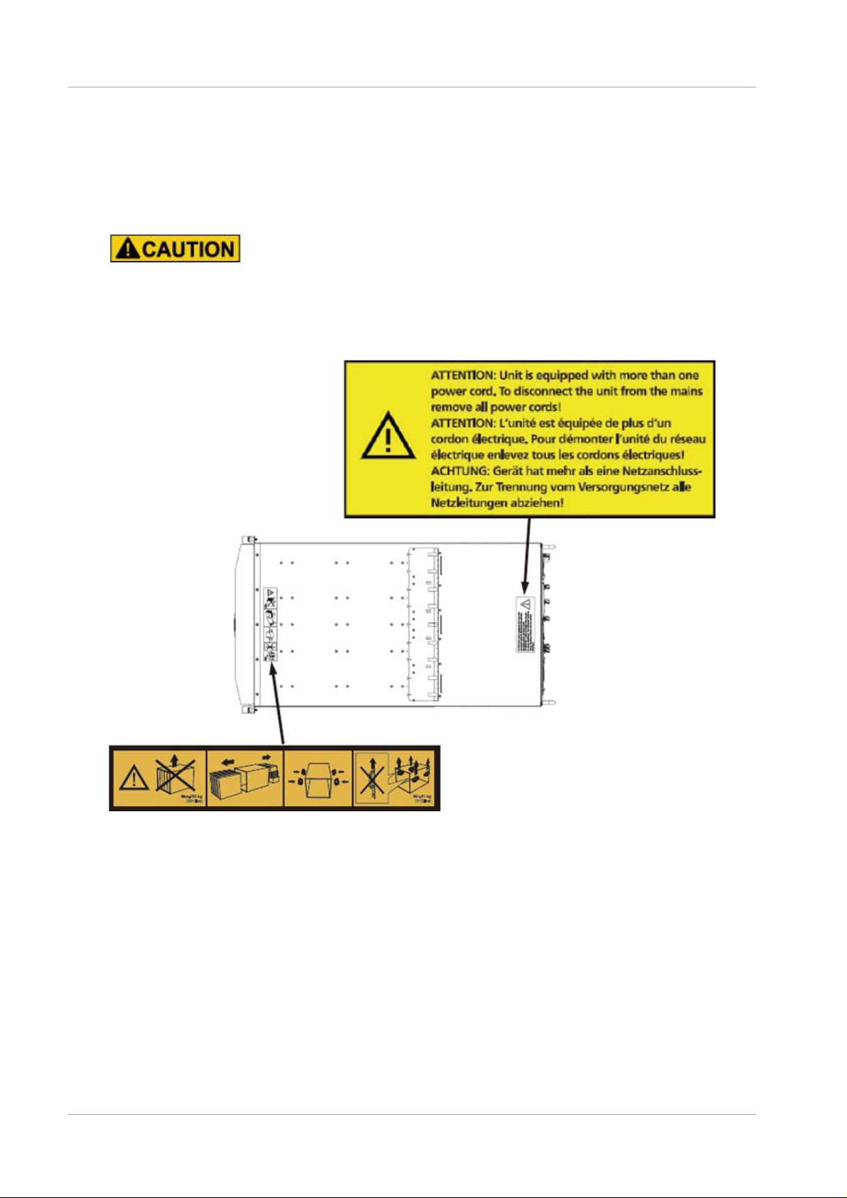
Warning labels
Never remove the warning labels.
Warning label location (the main cabinet top)
Warning label location (the main cabinet left)
iv
Page 6
Preface
C122-H007-01EN
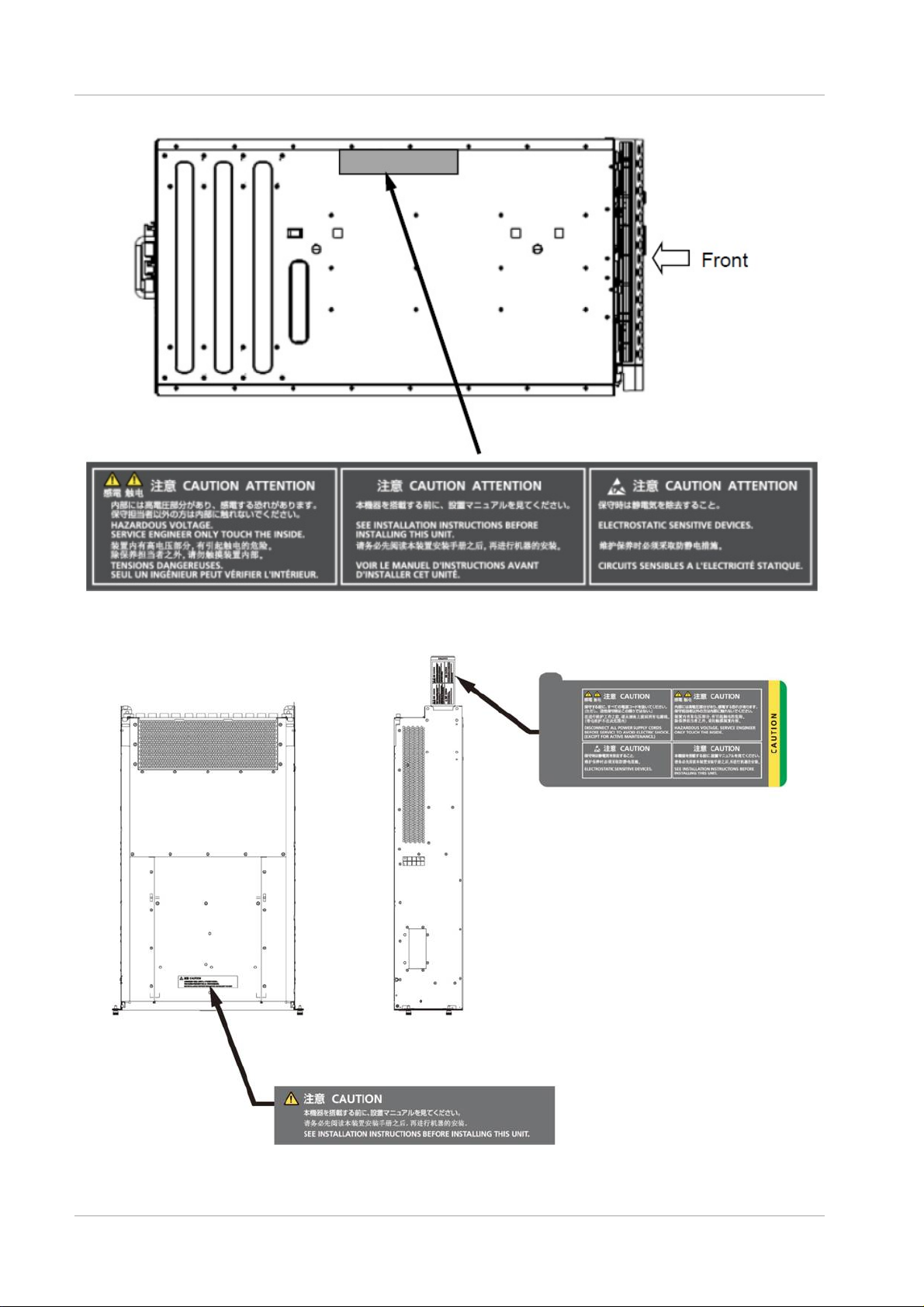
Warning label location (PCI_B ox)
v
Page 7

Preface
C122-H007-01EN
Notes on Handling the Product
About this product
This product is designed and manufactured for standard applications. Such applications include, but are not limited to,
general office work, personal and home use, and general industrial use. The product is not intended for applications that
require extremely high levels of safety to be guaranteed (referred to below as "safety-critical" applications). Use of the
product for a safety-critical application may present a significant risk of personal injury and/or death. Such applications
include, but are not limited to, nuclear reactor control, aircraft flight control, air traffic control, mass transit control, medical
life support, and missile launch control. Customers shall not use the product for a safety-critical application without
guaranteeing the required level of safety. Customers who plan to use the product in a safety-critical system are requested
to consult the Fujitsu sales representatives in charge.
Storage of accessories
Keep the accessories in a safe place because they are required for server operation.
Adding optional products
For stable operation of the PRIMEQUEST 2000 series server, use only a Fujitsu-certified optional product as an added
option.
Note that the PRIMEQUEST 2000 series server is not guaranteed to operate with any optional product not certified by
Fujitsu.
Maintenance
Only Fujitsu certified service engineers should perform the following tasks on this product and the
options provided by Fujitsu. Customers must not perform these tasks under any circumstances.
Otherwise, electric shock, injury, or fire may result.
- Newly installing or moving equipment
- Removing the front, rear, and side covers
- Installing and removing built-in options
- Connecting and disconnecting external interface cables
- Maintenance (repair and periodic diagnosis and maintenance)
Only Fujitsu certified service engineers should perform the following tasks on this product and the
options provided by Fujitsu. Customers must not perform these tasks under any circumstances.
Otherwise, product failure may result. PRIMEQUE ST 2000 Series General Description
- Unpacking an optional Fujitsu product, such as an optional adapter, delivered to the customer
Modifying or recycling the product
Modifying this product or recycling a secondhand product by overhauling it without prior approval
may result in personal injury to users and/or bystanders or damage to the product a nd/or ot her
property.
vi
Page 8

Preface
C122-H007-01EN
Note on erasing data from hard disks when disposing of the product or transferring it
Disposing of this product or transferring it as is may enable third parties to access the data on the hard disk and use it for
unforeseen purposes. To prevent the leakage of confidential information and important data, all of the data on the hard
disk must be erased before disposal or transfer of the product.
However, it can be difficult to completely erase all of the data from the hard disk. Simply initializing (reformatting) the hard
disk or deleting files on the operating system is insufficient to erase the data, even though the data appears at a glance to
have been erased. This type of operation only makes it impossible to access the data from the operating system.
Malicious third parties can restore this data.
If you save your confidential information or other important data on the hard disk, you should completely erase the data,
instead of simply carrying out the aforementioned operation, to prevent the data from being restored. To prevent important
data on the hard disk from being leaked when the product is disposed of or transferred, you will need to take care to erase
all the data recorded on the hard disk on your own responsibility.
Furthermore, if a software license agreement restricts the transfer of the software (operating system and application
software) on the hard disk in the server or other product to a third party, transferring the product without deleting the
software from the hard disk may violate the agreement. Adequate verification from this point of view is also necessary.
Product and service inquiries
For all product use and technical inquiries, contact the distributor where you purchased your product, or a Fujitsu sales
representative or systems engineer (SE). If you do not know the appropriate contact address for inquiries about the
PRIMEQUEST 20 00 series, use the Fujitsu contact line.
Fujitsu contact line
We accept Web inquiries. For details, visit our website:
https://www-s.fujitsu.com/global/contact/computing/PRMQST_feedback.html
Warranty
If a component failure occurs during the warranty period, we will repair it free of charge in accordance with the terms of the
warranty agreement. For details, see the warranty.
Before requesting a repair
If a problem occurs with the product, confirm the problem by referring to 11.2 Troubleshooting in the PRIMEQUEST 2000
Series Administration Manual (C122-E175ENEN). If the error recurs, contact your sales representative or a field engineer.
Confirm the model name and serial number shown on the label affixed to the right front of the device and report it. Also
check any other required items beforehand according to 11.2 Troubleshooting in the PRIMEQUEST 2000 Series
Administration Manual (C122-E175ENEN).
The system settings saved by the customer will be used during maintenance.
vii
Page 9

Preface
C122-H007-01EN
including
Manual
How to use this manual
This manual contains important information about the safe use of this product. Read the manual thoroughly to understand
the information in it before using this product. Be sure to keep this manual in a safe and convenient location for quick
reference.
Fujitsu makes every effort to prevent users and bystanders from being injured and to prevent property damage. Be sure to
use the product according to the instructions in this manual.
Manuals for the PRIMEQUEST 2000 series
The following manuals have been prepared to provide you with the information necessary to use the PRIMEQUEST 2000
series.
You can access HTML versions of these manuals at the following sites:
Japanese-language site: http://jp.fujitsu.com/platform/server/primequest/manual/2000/
Global site: http://www.fujitsu.com/global/services/computing/server/primequest/
http://manuals.ts.fujitsu.com/
Title
PRIMEQUEST 2000 Series
Getting Started Guide
PRIMEQUEST 2000 Series
Safety and Regulatory
Information
PRIMEQUEST 2000 Series
Errata and Addenda
PRIMEQUEST 2000 Series
General Description
SPARC Enterprise/
PRIMEQUEST C ommon
Installation Planning Manual
PRIMEQUEST 2000 Series
Hardware Installation Manual
PRIMEQUEST 2000 Series
Installation Manual
PRIMEQUEST 2000 Series
User Interface Operating
Instructions
PRIMEQUEST 2000 Series
Administration Manual
PRIMEQUEST 2000 Series
Tool Reference
Describes what manuals you should read and how to access
important information after unpacking the PRIMEQUEST 2000
series server. (This manual comes with the product.)
Contains important information required for using the
PRIMEQUEST 20 00 series safely.
Provides errata and addenda for the PRIMEQUEST 2000 series
manuals. This manual will be updated as needed.
Describes the functions and features of the PRIMEQU EST 2000
series.
Provides the necessary information and concepts you should
understand for installation and facility planning for SPARC
Enterprise and PRIMEQUEST installations.
Includes the specifications of and the installation location
requirements for the PRIMEQUEST 2000 series.
Describes how to set up the PRIMEQUEST 20 00 series server,
including the steps for installation preparation, initialization, and
software installation.
Describes how to use the Web-UI and UEFI to assure proper
operation of the PRIMEQUEST 2000 series server.
Describes how to use tools and software for system
administration and how to maintain the system (component
replacement and error notification).
Provides information on operation methods and settings,
details on the MMB, PSA, and UEFI functions.
Description
Manual code
C122-E170XA
C122-E171XA
C122-E182EN
C122-B025EN
C120-H007EN
C122-H007EN
C122-E174EN
C122-E176EN
C122-E175EN
C122-E177EN
viii
Page 10

Preface
C122-H007-01EN
problem occurs
Title
PRIMEQUEST 2000 Series
Message Reference
PRIMEQUEST 2000 Series
REMCS Installation Manual
PRIMEQUEST 2000 Series
Glossary
Lists the messages that may be displayed when a
during operation and describes how to respond to them.
Describes REMCS service installation and operation C122-E180EN
Defines the PRIMEQUEST 2000 series related terms and
abbreviations.
Description
Manual code
C122-E178EN
C122-E179EN
Related manuals
The following manuals relate to the PRIMEQUEST 2000 series.
You can access these manuals at the following site:
http://www.fujitsu.com/global/services/computing/server/primequest/
http://manuals.ts.fujitsu.com/
Contact your sales representative for inquiries about the ServerView manuals
Title
ServerView Suite ServerView
Operations Manager Quick
Installation (Windows)
ServerView Suite ServerView
Operations Manager Quick
Installation (Linux)
ServerView Suite ServerView
Installation Manager
ServerView Suite ServerView
Operations Manager Server
Management
ServerView Suite ServerView
RAID Management User Manual
ServerView Suite Basic Concepts Describes basic concepts about ServerView Suite. None
ServerView Operations Manager
Installation ServerView Agents for
Linux
ServerView Operations Manager
Installation ServerView Agents for
Windows
ServerView Mission Critical
Option User Manual
ServerView RAID Manager
VMware vSphere ESXi 5
Installation Guide
Describes how to install and start ServerView Operations
Manager in a Windows environment.
Describes how to install and start ServerView Operations
Manager in a Linux environment.
Describes the installation procedure using ServerView Installation
Manager.
Provides an overv iew of serv er moni tori ng usin g Serv erView
Operations Manager, and describes the user interface of
ServerView Operations Manager.
Describes RAID management using ServerView RAID Manager. None
Describes installation and update installation of ServerView Linux
Agent.
Describes installation and update installation of ServerView
Windows Agent.
Describes the necessary functions unique to PRIMEQUEST
(notification via the MMB, hot replacement command) and
ServerView Mission Critical Option (SVmco), which is required for
supporting these functions..
Describes the installation and settings required to use ServerView
RAID Manager on the VMware vSphere ESXi 5 server.
Description
None
None
None
None
None
None
None
None
Manual code
ix
Page 11
Preface
C122-H007-01EN
Title
MegaRAID SAS Software Provides technical information on using RAID controllers.
Refer to the manual from the SVS-ServerView Suite ServerBooks
DVD(Manual)2 supplied with the product or from the following
URL:
The Fujitsu Technology Solutions manuals server
http://manuals.ts.fujitsu.com/
MegaRAID SAS Device Driver
Installation
Modular RAID Controller
Installation Guide
Provides technical information on using RAID controllers.
Refer to the manual from the SVS-ServerView Suite ServerBooks
DVD(Manual)2 supplied with the product or from the following
URL:
The Fujitsu Technology Solutions manuals server
http://manuals.ts.fujitsu.com/
Provides technical information on using RAID controllers.
Refer to the manual from the SVS-ServerView Suite ServerBooks
DVD(Manual)2 supplied with the product or from the following
URL:
The Fujitsu Technology Solutions manuals server
http://manuals.ts.fujitsu.com/
Description
Manual code
None
None
None
Abbreviations
This manual uses the following product name abbreviations.
Formal product name Abbreviation
Microsoft ® Windows Server ® 2012 R2 Datacenter Windows, Windows Server 2012
Microsoft ® Windows Server ® 2012 R2 Standard
Microsoft ® Windows Server ® 2012 Datacenter
Microsoft ® Windows Server ® 2012 Standard
Microsoft ® Windows Server ® 2008 R2 Standard Windows, Windows Server 2008
Microsoft ® Windows Server ® 2008 R2 Enterprise
Microsoft ® Windows Server ® 2008 R2 Datacenter
Red Hat ® Enterprise Linux ® 6 (for Intel64) Linux, RHEL6, RHEL
Novell (R) SUSE(R) LINUX Enterprise Server 11 Service Pack 3 SLES11 SP3
Oracle Linux 6 (x86_64) Oracle Linux, Oracle Linux 6
VMware vSphere (R) 5 VMware, vSphere 5.x, VMware 5, VMwar e 5.x
VMware (R) ESXi (TM) 5 ESXi, ESX i 5, ESXi 5.x
Trademarks
- Microsoft, Windows, and Windows Server are trademarks or registered trademarks of Microsoft Corporation in the
United States and/or other countries.
- Linux is a registered trademark of Linus Torvalds.
- Red Hat, the Shadowman logo and JBoss are registered trademarks of Red Hat, Inc. in the U.S. and other countries.
- Oracle and Java are registered trademark of Oracle Corporation and its related company.
- Intel, Intel logo, Intel Inside, Intel Inside logo, Intel Atom, Intel Atom Inside, Intel Core, Core Inside, Intel vPro, vPro
x
Page 12

Preface
C122-H007-01EN
Inside, Celeron, Celeron Inside, Itanium, Itanium Inside, Pentium, Pentium Inside, Xeon, Xeon Phi, Xeon Inside,
Ultrabook are trademarks or registered trademarks of Intel Corporation.
- Ethernet is a registered trademark of Fuji Xerox Co., Ltd. in Japan and is a registered trademark of Xerox Corp. in the
United States and other countries.
- VMware is a trademark or registered trademark of VMware, Inc. in the United States and other countries.
- Novell and SUSE Linux Enterprise Server are trademarks of Novell, Inc.
- Xen is a trademark or registered trademark of Citrix Systems, Inc. or its subsidiaries in the United States and other
countries.
- Other company names and product names are the trademarks or registered trademarks of their respective owners.
- Trademark indications are omitted for some system and product names in this manual.
Notation
This manual uses the following fonts and symbols to express specific types of information.
Font or symbols Meaning Example
italics Title of a manual that you should refer to See the PRIMEQUEST 2000 Series
Installation Manual (C122-E174EN).
[ ]
Window names as well as the names of
buttons, tabs, and drop-down menus in
windows are enclosed in brackets.
Click the [OK] button.
Notation for the CLI (command line interface)
The following notation is used for commands.
Command syntax
Command syntax is represented as follows.
- Variables requiring the entry of a value are enclosed in angle brackets < >.
- Optional elements are enclosed in brackets [ ].
- Options for optional keywords are grouped in | (stroke) separated lists enclosed in brackets [ ].
- Options for required keywords are grouped in | (stroke) separated lists enclosed in braces { }.
Command syntax is written in a box.
Remarks
The command output shown in the PDF manuals may include line feeds at places where there is no line feed symbol
(\ at the end of the line)
Notes on notations
- If you have a comment or request regarding this manual, or if you find any part of this manual unclear, please take a
moment to share it with us by filling in the form at the following webpage, stating your points specifically, and sending
the form to us:
https://www-s.fujitsu.com/global/contact/computing/PRMQST_feedback.html
- The contents of this manual may be revised without prior notice.
- In this manual, the Management Board and MMB firmware are abbreviated as "MMB."
- In this manual, IOU_10GbE and IOU_1GbE are collectively referred to as IO Units.
- Screenshots contained in this manual may differ from the actual product screen displays.
- The IP addresses, configuration information, and other such information contained in this manual are display
examples and differ from that for actual operation.
xi
Page 13

Preface
C122-H007-01EN
- The PDF file of this manual is intended for display using Adobe® Reader® in single page viewing mode at 100%
zoom.
This manual shall not be reproduced or copied without the permission of Fujitsu Limited.
Copyright 2014 FU JITSU LIM ITED
xii
Page 14

Preface
C122-H007-01EN
Contents
Preface ................................................................................................................................................................................................................ i
Installation Data .................................................................................................................................................................... 1 CHAPTER 1
Configuration Contents of Device ................................................................................................................................................. 1
1.1
1.2 External Overview of Device ......................................................................................................................................................... 1
1.2.1 External Overview of Device (Main equipment) ...................................................................................................................... 1
1.2.2 External Overview of Device (PCI_Box) .................................................................................................................................. 5
1.3 Installation Specifications ............................................................................................................................................................... 6
1.3.1 Installation specifications (PRIMEQUEST 2400E) ................................................................................................................. 6
1.3.2 Installation Specifications (PRIMEQUEST 2800E) ................................................................................................................. 8
1.3.3 Installation Specifications (PRIMEQUEST 2800B) .............................................................................................................. 10
1.3.4 Installation Specifications (PCI_Box) .................................................................................................................................... 12
1.4 Installation Area ........................................................................................................................................................................... 13
1.5 Flow of Cooling Air and Exhaust Air of Installation .................................................................................................................... 14
1.5.1 Flow of Cooling Air and Exhaust Air (Main Cabinet) ............................................................................................................ 14
1.5.2 Flow of Cooling Air and Exhaust (PCI_Box)......................................................................................................................... 14
1.6 Installation Environment ............................................................................................................................................................. 15
1.6.1 Dust ........................................................................................................................................................................................ 15
1.6.2 Corrosive Gas ........................................................................................................................................................................ 15
1.6.3 Sea Water (Salt Damage) ..................................................................................................................................................... 15
1.7 Safety Measures ......................................................................................................................................................................... 15
Connected Information ..................................................................................................................................................... 16 CHAPTER 2
Connection summary ................................................................................................................................................................. 16
2.1
2.2 Connection of signal cable ......................................................................................................................................................... 17
2.2.1 Basic interface and peripheral ............................................................................................................................................... 17
2.2.2 Details of external interface connection ................................................................................................................................ 17
2.3 Power cable connection ............................................................................................................................................................. 22
2.3.1 Power Supply Cable Connection (PRIMEQUEST 2400E) ................................................................................................. 22
2.3.2 Power Cables Connections (PRIMEQUEST 2800E/2800B) .............................................................................................. 25
2.3.3 Power Cable Connections (PCI_Box) .................................................................................................................................. 27
2.4 Connection Specifications of Input Power ................................................................................................................................. 30
2.4.1 Input Power Connection Specifications (Base Cabinet) ...................................................................................................... 30
2.4.2 Input Power Supply Connection Specifications (PCI_Box) ................................................................................................. 30
2.4.3 Power Distribution Box and Distribution Panel ..................................................................................................................... 31
2.5 Free Access Underfloor Connection of Power Cable ............................................................................................................... 31
2.6 Cutoff Characteristics of Distribution Panel (At the time of connecting power distribution box) .............................................. 32
Notes on Carrying In and Installing the Product .............................................................................................................. 34 CHAPTER 3
Elevator Load Conditions ........................................................................................................................................................... 34
3.1
3.2 Earthquake Preparedness Measures ....................................................................................................................................... 34
Appendix A Racks .......................................................................................................................................................................................... 35
A.1 Rack Mounting ..................................................................................................................................................................................... 35
A.2 Rack Mounting Requirements ............................................................................................................................................................ 35
A.2.1 Requirements for mounting in a Fujitsu 19-inch rack ................................................................................................................. 35
xiii
Page 15

Preface
C122-H007-01EN
A.2.2 Requirements for mounting in a third party's rack ....................................................................................................................... 37
xiv
Page 16

Preface
C122-H007-01EN
Figures
FIGURE 1.1 PRIMEQUEST 2400E/2800E front view ........................................................................................................................... 1
FIGURE 1.2 PRIMEQUEST 2400E/2800E rear view ............................................................................................................................ 2
FIGURE 1.3 PRIMEQUEST 2400E/2800E top view.............................................................................................................................. 2
FIGURE 1.4 PRIMEQUEST 2400E/2800E right side view .................................................................................................................... 2
FIGURE 1.5 PRIMEQUEST 2800B front view ....................................................................................................................................... 3
FIGURE 1.6 PRIMEQUEST 2800B rear view ........................................................................................................................................ 3
FIGURE 1.7 PRIMEQUEST 2800B top view .......................................................................................................................................... 3
FIGURE 1.8 PRIMEQUEST 2800B right side view ................................................................................................................................ 4
FIGURE 1.9 Front View of PCI_Box ........................................................................................................................................................ 5
FIGURE 1.10 Rear View of PCI_Box ...................................................................................................................................................... 5
FIGURE 1.11 Top View of PCI_Box ........................................................................................................................................................ 5
FIGURE 1.12 Right Side View of PCI_Box ............................................................................................................................................. 5
FIGURE 1.13 Service Area at the time of installing 19 inch rack model ............................................................................................. 13
FIGURE 1.14 Flow of Cooling Air and Exhaust Air (Main Cabinet)..................................................................................................... 14
FIGURE 1.15 Flow of Cooling Air and Exhaust (PCI_Box) ................................................................................................................. 14
FIGURE 2.1 Summary of Device Connection ...................................................................................................................................... 16
FIGURE 2.2 External interface connection figure of (PRIMEQUEST 2400E (Front surface)) .......................................................... 18
FIGURE 2.3 External interface connection figure of (PRIMEQUEST 2400E (Back surface)) .......................................................... 18
FIGURE 2.4 External interface connection figure of (PRIMEQUEST 2800E (Front surface)) .......................................................... 19
FIGURE 2.5 External interface connection figure of (PRIMEQUEST 2800E (Back surface)) .......................................................... 19
FIGURE 2.6 External interface connection figure of (PRIMEQUEST 2800B (Front surface)) .......................................................... 20
FIGURE 2.7 External interface connection figure of (PRIMEQUEST 2800B (Back surface)) .......................................................... 20
FIGURE 2.8 Details of external interface (MMB) .................................................................................................................................. 21
FIGURE 2.9 Details of external interface (I OU_1G bE) ........................................................................................................................ 21
FIGURE 2.10 Details of external interface (IOU_10GbE) .................................................................................................................... 21
FIGURE 2.11 Details of external interface (DU) ................................................................................................................................... 21
FIGURE 2.12 Details of external interface (PCI_Box).......................................................................................................................... 22
FIGURE 2.13 100V Standard Power Feed Configuration (Single power feed, no Redundant Power Feed) .................................. 22
FIGURE 2.14 100V Redundant Power Feed Configuration (Single power feed, Redundant Power Feed) .................................... 23
FIGURE 2.15 Standard Configuration of 200 V (single power feed, no redundant power feed) with Power Distribution Box
Connection ...................................................................................................................................................................................... 23
FIGURE 2.16 200 V Redundant Power Feed Configuration (single power feed, redundant power feed) with Power Distribution
Box Connection .............................................................................................................................................................................. 24
FIGURE 2.17 200 V Dual Power Feed Configuration with Power Distribution Box Connection ....................................................... 24
FIGURE 2.18 200V Standard Configuration (single power feed and no redundant power feed) with Power Distribution Box
Connection ...................................................................................................................................................................................... 25
FIGURE 2.19 200 V Redundant Power Feed Configuration (single power feed, redundant power feed) with Power Distribution
Box Connection .............................................................................................................................................................................. 26
FIGURE 2.20 200 V Dual Power Feed Configuration with Power Distribution Box Connection ....................................................... 27
FIGURE 2.21 100 V Configuration (Single power feed, no Redundant power feed) ......................................................................... 27
FIGURE 2.22 100 V Redundant power feed configuration (Single power feed, redundant power feed) ......................................... 28
FIGURE 2.23 200V Standard configuration (single power feed, no redundant power feed) power distribution box connection .... 28
xv
Page 17

Preface
C122-H007-01EN
FIGURE 2.24 200 V Redundant Power Feed Configuration (Single power feed, Redundant Power Feed) Power Distribution Box
Connection ...................................................................................................................................................................................... 29
FIGURE 2.25 200 V Dual Power Feed Configuration with Power Distribution Box Connection ....................................................... 29
FIGURE 2.26 When Underfloor Height is less than 300mm (11.8 in) ................................................................................................ 31
FIGURE 2.27 When the under floor height is 300 mm (11.8 in) or more. ........................................................................................... 31
FIGURE 2.28 Characteristics of Breaker of Distribution Panel ............................................................................................................ 33
FIGURE A.1 Example of rack mounting ............................................................................................................................................... 36
FIGURE A.2 Length of rack ................................................................................................................................................................... 38
FIGURE A.3 Width of rack ..................................................................................................................................................................... 38
FIGURE A.4 Format of rack posts ........................................................................................................................................................ 39
xvi
Page 18

Preface
C122-H007-01EN
Tables
TABLE 1.1 Name and Contents of Configuration of Each device .......................................................................................................... 1
TABLE 1.2 Installation Specifications (PRIMEQUEST 2400E) .............................................................................................................. 6
TABLE 1.3 Installation Specifications (PRIMEQUEST 2800E) .............................................................................................................. 8
TABLE 1.4 Installation Specifications (PRIMEQUEST 2800B) ........................................................................................................... 10
TABLE 1.5 Installation Specifications (PCI_Box) ................................................................................................................................. 12
TABLE 1.6 Permissible Level of Corrosive Gas ................................................................................................................................... 15
TABLE 2.1 Notes for Device connection .............................................................................................................................................. 17
TABLE 2.2 Power Cable Specifications (Base Cabinet)...................................................................................................................... 30
TABLE 2.3 Power Cable Specification (PCI_Box) ............................................................................................................................... 30
TABLE 2.4 Power Supply Cable Specifications of Power Distribution Box and Distribution Panel ................................................... 31
TABLE 2.5 Characteristic Condition of Distribution Panel Breaker ..................................................................................................... 32
TABLE 3.1 Elevator load conditions ...................................................................................................................................................... 34
TABLE A.1 Recommended racks for mounting ................................................................................................................................... 35
TABLE A.2 PRIMEQUEST 2000 series external dimensions............................................................................................................. 35
TABLE A.3 Structural condition of rack ................................................................................................................................................. 37
xvii
Page 19

CHAPTER 1 Installation Data
C122-H007-01EN
Equipment Name
Content Configuration
Size
(Height)
PRIMEQUEST
2400E
Maximum 2 SB (Maximum 4 CPU), Maximum 4 IOU are available.
10 U
PRIMEQUEST
2800E/2800B
Maximum 4 SB (Maximum 8 CPU), Maximum 4 IOU are available.
PCI_Box
Device for extending PCI Express Slot.
One PCI_Box has 12 PCI Express slots.
4U
1.1 Configuration Contents of Device
Installation Data CHAPTER 1
It explains the various data used while installing various drawings for device configuration, device overview,
installation specification and layout.
1.1 Configuration Contents of Device
It shows the name and contents of configuration of each device.
TABLE 1.1 Name and Contents of Configuration of Each device
Maximum 4 units can be connected in PRIMEQUEST 2400E/2800E.
Remarks
Each device shown in “TABLE 1.1 Name and Contents of Configuration of Each device” is installed in 19
inch rack of EIA standard.
For the details on 19 inch rack, contact the distributor where you purchased your product, or your sales
representative.
1.2 External Overview of Device
This section describes the External Overview of each equipment.
1.2.1 External Overview of Devic e (M ai n equi pm e nt )
External Overview of device (Front view, Rear view, Top view, Right side view) of PRIMEQUEST 2000
Series is shown below.
PRIMEQUEST 2400E/2800E
FIGURE 1.1 PRIMEQUEST 2400E/2800E front view
1
Page 20

CHAPTER 1 Installation Data
C122-H007-01EN
1.2 External Overview of Device
FIGURE 1.2 PRIMEQUEST 2400E/2800E rear view
FIGURE 1.3 PRIMEQUEST 2400E/2800E top view
FIGURE 1.4 PRIMEQUEST 2400E/2800E right side view
2
Page 21

CHAPTER 1 Installation Data
C122-H007-01EN
1.2 External Overview of Device
PRIMEQUEST 2800B
FIGURE 1.5 PRIMEQUEST 2800B front view
FIGURE 1.6 PRIMEQUEST 2800B rear view
FIGURE 1.7 PRIMEQUEST 2800B top view
3
Page 22

CHAPTER 1 Installation Data
C122-H007-01EN
1.2 External Overview of Device
FIGURE 1.8 PRIMEQUEST 2800B right side view
4
Page 23

CHAPTER 1 Installation Data
C122-H007-01EN
1.2 External Overview of Device
1.2.2 External Overview of Device (PCI_Box)
Device External Overview (Front view, Rear view, Top view, Right side view) of PCI_Box is shown below.
FIGURE 1.9 Front View of PCI_Box
FIGURE 1.10 Rear View of PCI_Box
FIGURE 1.11 Top View of PCI_Box
FIGURE 1.12 Right Side View of PCI_Box
5
Page 24

CHAPTER 1 Installation Data
C122-H007-01EN
Item
Contents
External
[mm(in.)]
Width
445(17.52)
Length(*1)
782(30.79)
Height
438(17.25) 10U
Mass [kg(lb)] (*2)
128(282)
Conditions for
Maximum Calorific value
Input
Interruptible Power
11,887(11,266)
High efficiency Power
11,805(11,189)
Input
100V
Interruptible Power
12,528(11,874)
Displacement
Recommended Environmental
temperature
10(353)
Maximum
24(848)
Temperature and
Operati
Temperature[ºC(ºF)]
(*5)
Humidity[%RH]
20 to 80
Highest Wet bulb
Temperature[ºC(ºF)]
29(84.2)
Down
Temperature[ºC(ºF)]
0 to 50(32 to 122)
Humidity[%RH]
8 to 80
Highest Wet bulb
Temperature[ºC(ºF)]
29(84.2)
Noise[dB](*7,*8)
60
Acoustic power level[B](*8)
7.8
Permissible Vibration
Operating Time(including waiting
time)
4.0(400)( synthetic
seismic wave)
Down time(*9)
10.0(1000)( synthetic
seismic wave)
Permissible dust level[mg/m3]
0.15
Power
Input Voltage and Pulse number
200 to 240VAC±10%
1φ
Frequency and Fluctuation
50/60 Hz+2/-4%
Maximum Power
Operating
Input
Interruptible
Supply(*13)
4.17 kW/4.39 kVA
High efficiency
supply(*13)
4.04 kW/4.25 kVA
Input
100 V
Interruptible
Supply(*13)
4.42 kW/4.65 kVA
Standby time
0.079kW
Power Factor(*10)
0.95 or more
Inrush current[A][Rush time](*11)
20 or less
Leak current[mA](*12)
6.8 or less at 200V
3.5 or less at 100V
1.3 Installation Specifications
1.3 Installation Specifications
This section explains installation specification of each equipment.
1.3.1 Installation specifications (PRIMEQUEST 2400E)
TABLE 1.2 Installation Specifications (PRIMEQUEST 2400E)
Dimensions
Air
Conditioning
Conditions
[kJ/h(BTU/h)]
[m3/min(ft3/min)](*3)
Humidity Conditions(*4)
[m/s2(gal)]
Voltage:
200V
Voltage:
ng Time
Time(*6
)
Supply(*13)
supply(*13)
Supply(*13)
100 to 120VAC±10%
*1: Dimensions without protrusions (Dimensions including the front cover are 832mm(32.76in)).
Consumption
/Apparent Power
time
Voltage :
200 V
Voltage :
6
Power
Power
Power
Page 25

CHAPTER 1 Installation Data
C122-H007-01EN
1.3 Installation Specifications
*2: Numeric value when each optional device is mounted for maximum number of options.
However, rail for mounting rack (5.7kg) and cable type are not inclu ded.
Mass as per the installation configuration can be calculated using formula as shown below.
Device Mass: 78 + (11.1* A) + (2.5* B) + (1.8* C) + (3.3* D) [kg]
A= Number of mounted SB (Minimum 1 to Maximum 2)
B=Number of mounted IOU (Minimum 1 to Maximum 4)
C=Number of mounted extended PSU (Minimum 2 to Maximum 4)
D=Number of mounted DU (Minimum 0 to Maximum 2)
*3: If the device is overloaded or if abnormality is detected even though the recommended environmental
temperature is used, the FAN rotates at high-speed.
*4: Protect from condensation
*5: Temperature conditions changes according to installation location above sea level.
For 0 to 1000 m (0 to 3281 ft) above sea level, temperature range at the time of installation: 5 to 35ºC
(41 to 95.0ºF)
For 1000 to 1500 m (3281 to 4921 ft) above sea level, temperature range at the time of installation: 5 to
33ºC (41 to 91.4ºF)
For 1500 to 2000 m (4921 to 6562 ft) above sea level, temperature range at the time of installation: 5 to
31°C (41 to 87.8°F)
For 2000 to 3000 m (6562 to 9843 ft) above sea level, temperature range at the time of installation: 5 to
29°C (41 to 84.2°F)
Error of + 100m in the sea level settings of the location of installation is permissible.
*6: Downtime is the condition in which the device is packed and maintained.
*7: Level of noise which is actually heard varies as per the mounting condition of the position from where the
noise is heard or the position of rack.
*8: Level of noise and level of acoustic power changes according to the Hardware configuration, the
processing load and the environmental temperature.
*9: Downtime is the condition in which the device is installed. However, the power is switched off.
*10: Value at the time of operations.
*11: Value of 1 input cable
*12: Value of 1 device
*13: Interruptible power supply is the built-in PSU (80 PLUS SILVER supported), high efficiency power
supply is the built-in PSU (80 PLUS PLATINUM supported)
7
Page 26

CHAPTER 1 Installation Data
C122-H007-01EN
Items
Contents
Dimensions
Width
445(17.52)
Depth (*1)
782(30.79)
Length
438(17.25) 10U
Mass [kg (lb)] (*2)
150(331)
Conditions for
Max. calor ific
[kJ/h (BTU/h)]
Interruptible power source
17,712(16,787)
High efficiency power supply (*13)
17,388(16,480)
Displacement
Recommended environmental
temperature
12(424)
Max.
28(989)
Temperature and
At the time
Temperature [°C (°F)]]
(*5)
Humidity [%RH]
20 to 80
Max wet bulb
temperature [°C (°F)]]
29 (84.2)
Downtime
Temperature [°C (°F)]]
0 to 50 (32 to 122)
Humidity [%RH]
8 to 80
Max wet bulb
temperature [°C (°F)]]
29 (84.2)
Noise [dB] (*7, *8)
60
Acoustic power level [B] (*8)
7.8
Permissible
At the time of operation (Including
standby)
4.0 (400) (Composi te seismic
wave)
Downtime (*9)
10.0 (1000) (Composite
seismic wave)
Permissible dust level [mg/m3]
0.15
Power supply
Input voltage and source resultant pulse number
200 to 240 VAC±10 %
1φ
Frequency and fluctuating Range
50/60 Hz + 2/-4%
Max power
At the time
Interruptible power
source (*13)
6.11 kW/6.43 kVA
High efficiency power
supply (*13)
5.92 kW/6.23 kVA
Downtime
0.084 kW
Power factor (*10)
0.95 or more
Inrush current [A] [Rush hours] (*11)
20 or less
Leak current [mA] (*12)
6.9 or less
1.3 Installation Specifications
1.3.2 Installation Specific a ti ons ( P RIMEQUEST 2800E)
TABLE 1.3 Installation Specifications (PRIMEQUEST 2800E)
[mm (in.)]
air conditioner
conditions
value
[m3/min (ft3/min)]
(*3)
Humidity
conditions (*4)
Vibration [m/s2
(gal)]
consumption /
apparent power
of operation
(*6)
of operation
*1: Dimensions without protrusions (832 mm(32.76in) including front cover)
*2: Numeric value when each optional device is mounted for maximum number of options.
However, rail for mounting rack (5.7kg) and cable type are not inclu ded.
Mass as per the installation configuration can be calculated using formula as shown below.
Device mass = 78 + (11.1 * A) + (2.5 * B) + (1.8 * C) + (3.3 * D) [kg]
A = Number of mounted SB (Minimum 1 to Maximum 4)
B= Number of mounted IOU (Minimum 1 to Maximum 4)
C= Number of mounted PSU (Minimum 2 to Maximum 6)
D= Number of mounted DU (Minimum 0 to Maximum 2)*3: There are cases when device is overloaded or
when abnormality is detected, FAN rotates at high-speed even if recommended environmental
temperature is used.
*4: Protect from condensation.
*5: Temperature condition changes accord ing to the inst alla ti on locat ion abov e sea lev el.
For 0 to 1000 m (0 to 3281 ft) above sea level, temperature range at the time of installation: 5 to 35°C
(41 to 95°F)
For 1000 to 1500 m (3281 to 4921 ft) above sea level, temperature range at the time of installation: 5 to
33°C (41 to 91.4°F)
For 1500 to 2000 m (4921 to 6562 ft) above sea level, temperature range at the time of installation: 5 to
31°C (41 to 87.8°F)
8
Page 27

CHAPTER 1 Installation Data
C122-H007-01EN
1.3 Installation Specifications
For 2000 to 3000 m (6562 to 9843 ft) above sea level, temperature range at the time of installation: 5 to
29°C (41 to 84.2°F)
Error of + 100m in the sea level settings of the location of installation is permissible.
*6: Downtime is the condition in which the device is packed and maintained.
*7: Level of noise which is actually heard varies as per the mounting condition of the position from where the
noise is heard or the position of rack.
*8: Level of noise and the level of acoustic power changes according to the Hardware configuration, the
processing load and the environmental temperature.
*9: Downtime is the condition in which the device is installed. However, the power is switched off.
*10: Value at the time of operations.
*11: Value of 1 input cable
*12: Value of 1 device
*13: Interruptible power supply is the built-in PSU (80 PLUS SILVER supported), high efficiency power
supply is the built-in PSU (80 PLUS PLATINUM supported)
9
Page 28

CHAPTER 1 Installation Data
C122-H007-01EN
Items
Contents
Dimensions
Width
445(17.52)
Depth (*1)
782(30.79)
Length
438(17.25) 10U
Mass [kg (lb)] (*2)
143(315)
Conditions for
Max. calor ific
[kJ/h (BTU/h)]
Interruptible power source
16,992(16,105)
High efficiency power supply (*13)
16,740(15,866)
Displacement
Recommended environmental
temperature
12(424)
Max.
28(989)
Temperature and
At the time
Temperature [°C (°F)]]
(*5)
Humidity [%RH]
20 to 80
Max wet bulb
temperature [°C (°F)]]
29 (84.2)
Downtime
Temperature [°C (°F)]]
0 to 50 (32 to 122)
Humidity [%RH]
8 to 80
Max wet bulb
temperature [°C (°F)]]
29 (84.2)
Noise [dB] (*7, *8)
60
Acoustic power level [B] (*8)
7.8
Permissible
At the time of operation (Including
standby)
4.0 (400) (Composi te seismic
wave)
Downtime (*9)
10.0 (1000) (Composite
seismic wave)
Permissible dust level [mg/m3]
0.15
Power supply
Input voltage and source resultant pulse number
200 to 240 VAC±10 %
1φ
Frequency and fluctuating Range
50/60 Hz + 2/-4%
Max power
At the time
Interruptible power
source (*13)
6.00 kW/6.32 kVA
High efficiency power
supply (*13)
5.81 kW/6.12 kVA
Downtime
0.084 kW
Power factor (*10)
0.95 or more
Inrush current [A] [Rush hours] (*11)
20 or less
Leak current [mA] (*12)
6.9 or less
1.3 Installation Specifications
1.3.3 Installation Specific a ti ons ( P RIMEQUEST 2800B)
TABLE 1.4 Installation Specifications (PRIMEQUEST 2800B)
[mm (in.)]
air conditioner
conditions
value
[m3/min (ft3/min)]
(*3)
Humidity
conditions (*4)
Vibration [m/s2
(gal)]
consumption /
apparent power
of operation
(*6)
of operation
*1: Dimensions without protrusions
*2: Numeric value when each optional device is mounted for maximum number of options.
However, rail for mounting rack (5.7kg) and cable type are not included.
Mass as per the installation configuration can be calculated using formula as shown below.
Device mass = 77 + (9.6 * A) + (2.5 * B) + (1.8 * C) + (3.3 * D) [kg]
A = Number of mounted SB (Minimum 1 to Maximum 4)
B= Number of mounted IOU (Minimum 1 to Maximum 4)
C= Number of mounted PSU (Minimum 2 to Maximum 6)
D= Number of mounted DU (Minimum 0 to Maximum 2)
*3: There are cases when device is overloaded or when abnormality is detected, FAN rotates at high-speed
even if recommended environmental temperature is used.
*4: Protect from condensation.
*5: Temperature condition changes accord ing to the inst alla ti on locat ion abov e sea lev el.
For 0 to 1000 m (0 to 3281 ft) above sea level, temperature range at the time of installation: 5 to 35°C
(41 to 95°F)
10
Page 29

CHAPTER 1 Installation Data
C122-H007-01EN
1.3 Installation Specifications
For 1000 to 1500 m (3281 to 4921 ft) above sea level, temperature range at the time of installation: 5 to
33°C (41 to 91.4°F)
For 1500 to 2000 m (4921 to 6562 ft) above sea level, temperature range at the time of installation: 5 to
31°C (41 to 87.8°F)
For 2000 to 3000 m (6562 to 9843 ft) above sea level, temperature range at the time of installation: 5 to
29°C (41 to 84.2°F)
Error of + 100m in the sea level settings of the location of installation is permissible.
*6: Downtime is the condition in which the device is packed and maintained.
*7: Level of noise which is actually heard varies as per the mounting condition of the position from where the
noise is heard or the position of rack.
*8: Level of noise and the level of acoustic power changes according to the Hardware configuration, the
processing load and the environmental temperature.
*9: Downtime is the condition in which the device is installed. However, the power is switched off.
*10: Value at the time of operations.
*11: Value of 1 input cable
*12: Value of 1 device
*13: Interruptible power supply is the built-in PSU (80 PLUS SILVER supported), high efficiency power
supply is the built-in PSU (80 PLUS PLATINUM supported)
11
Page 30

CHAPTER 1 Installation Data
C122-H007-01EN
Item
Contents
Dimensions
Width
482 (18.98)
Depth
740 (29.13)
Length
175 (6.89) 4U
Mass [kg (lb)] (*2)
35 (77)
Conditions
Max. calorific value [kJ/h (BTU/h)]
1656 (1570)
Displacement [m3/min
FAN low speed (Low)
3 (106)
FAN medium speed (Normal)
4 (141)
FAN high speed (High)
5 (177)
Temperature
At time of
Temperature [°C (°F)]]
(*5)
Humidity [%RH]]
20 to 80
Max wet bulb temperature [°C
(°F)]]
29 (84.2)
Downtime
Temperature [°C (°F)]]
0 to 50 (32 to 122)
Humidity [%RH]]
8 to 80
Max wet bulb temperature [°C
(°F)]]
29 (84.2)
Noise [dB] (*7, *8)
(Included in
installation)
Acoustic power level [B] (*8)
(Included in
installation)
Permissibl
At the time of operation (Including standby)
4.0 (400) (Composite
seismic wave)
Downtime (*9)
10.0 (1000)
wave)
Permissible dust level [mg/m3]
0.15
Power
Input voltage and source resultant pulse number
200 to 240 VAC±10 %
1φ
Frequency and fluctuating Range
50/60 Hz + 2/-4%
Max
power
At the time of
operation
Input voltage: 200 V
450W/475 VA
Input voltage: 100 V
460W/485 VA
Downtime
Input voltage: 200 V
10W/40VA
Input voltage: 100 V
10W/35 VA
Power factor (*10)
More than equal to
0.95
Inrush current [A] [Rush hours] (*11)
Less than or equal to
25
Leak current [mA] (*12)
Less than or equal to
3.5
1.3 Installation Specifications
1.3.4 Installation Specific a ti ons ( P CI_Box)
TABLE 1.5 Installation Specifications (PCI_Box)
[mm (in)]
for air
conditioner
(ft3/min)] (*3)
Supply
conditions
and Humidity
condition (*4)
e Vibration
2
[m/s
(gal)]
power
consumpti
on /
apparent
operation
(*6)
(Composite seismic
100 to 120 VAC±10 %
*1: Dimensions without protrusions.
*2: Numeric value when each optional device is mounted for maximum number of options.
*3: If the device is overloaded or if abnormality is detected even though the recommended environmental
temperature is used, the FAN rotates at high-speed.
*4: Protect from condensation.
*5: Temperature condition changes according to the installation location above sea level.
For 0 to 1000 m (0 to 3281 ft) above sea level, temperature range at the time of installation: 5 to 35°C
(41 to 95°F)
For 1000 to 1500 m (3281 to 4921 ft) above sea level, temperature range at the time of installation: 5 to
33°C (41 to 91.4°F)
For 1500 to 2000 m (4921 to 6562 ft) above sea level, temperature range at the time of installation: 5 to
31°C (41 to 87.8°F)
For 2000 to 3000 m (6562 to 9843 ft) above sea level, temperature range at the time of installation: 5 to
29°C (41 to 84.2°F)
Error of + 100m in the sea level settings of the location of installation is permissible.
*6: Downtime is the condition in which the device is packed and maintained.
12
Page 31

CHAPTER 1 Installation Data
C122-H007-01EN
Number
Description
(1)
Rear side maintenance area
(2)
Rack
(3)
Front side maintenance area
(4)
Rack width
Model 2724/2737/2742, PCRM1 724S/742S/724A/742A
700 mm
Model 2616/2624/2642, PCRM1 616S/624S/642S
600 mm
1.4 Installation Area
*7: Level of noise which is actually heard varies as per the mounting condition of the position from where the
noise is heard or the position of rack.
*8: Level of noise and level of acoustic power changes according to the environmental temperature
*9: Downtime is the condition in which the device is installed. However, the power is switched off.
*10: Value at the time of operations.
*11: Value of 1 input cable
*12: Value of 1 device
1.4 Installation Area
Here, the installation area and the service area when the PRIMEQUEST 2000 series or the PCI_Box is
installed on 19-inch made by Fujitsu rack are ex plained.
The installation area and the service area differ according to the installed 19-inch rack.
For details on the 19-inch racks, contact the distributor where you purchased your product, or your sales
representative.
FIGURE 1.13 Service Area at the time of installing 19 inch rack model
13
Page 32

CHAPTER 1 Installation Data
C122-H007-01EN
Number
Description
(1)
Inspiration
(2)
Exhaust
(3)
Location of exhaust
Number
Description
(1)
Inspiration
(2)
Exhaust
(3)
Location of exhaust
1.5 Flow of Cooling Air and Exhaust Air of Installation
1.5 Flow of Cooling Air and Exhaust Air of Installation
Here, the flow of the cooling air and the exhaust of each device are explained.
Note
Flow of cooling air and exhaust air should be considered while studying the installation of a device. If device
is installed without considering them, it may get affected by inhaling the exhaust air from the other device.
Especially, the device detecting the intake air temperature may raise alarm indicating abnormality.
1.5.1 Flow of Cooling Air and Exhaus t Air (Main Cabinet)
FIGURE 1.14 Flow of Cooling Air and Exhaust Air (Main Cabinet)
1.5.2 Flow of Cooling Air and E x ha us t (PCI_ Box )
FIGURE 1.15 Flow of Cooling Air and Exhaust (PCI_Box)
14
Page 33

CHAPTER 1 Installation Data
C122-H007-01EN
Name of gas
Permissible level
Hydrogen sulfide (H2S)
7.1ppb or less
Sulfur dioxide (Sulfur oxide)(SO2)
37ppb or less
Hydrogen chloride (HCL)
6.6ppb or less
Chlorine (CI2)
3.4ppb or less
Hydrogen fluoride (HF)
3.6ppb or less
Nitrogen dioxide (Nitrogen oxides)(NO2)
52ppb or less
Ammonia(NH3)
420ppb or less
Ozone(O3)
5ppb or less
Fluid vapor
0.2mg/m3 or less
1.6 Installation Environment
1.6 Installation Environment
This section describes the installation environment of the base cabinet and PCI_Box.
1.6.1 Dust
Suspended Particles
Suspended particles in a computer room should not exceed 0.15mg/m3. A computer is designed in such a
way that it withstands the suspended particles. This value is permissible in an ordinary office. However, this
value can be maintained in the ordinary computer room if there is less outdoor air infiltration having
suspended particles like dust and if there is no smoke of cigarettes.
Dust Removal
The suspended particles like dust are collected in the filter of an air conditioner. The dust should be removed
from the computer room by cleaning floor surfaces and underfloor periodically. Cleaning is necessary in the
following cases.
When the computer room is ready, and before bringing in the computers
At the time of repairing the computer room
At the time of shifting the computers and re-arranging the devices
1.6.2 Corrosive Gas
Corrosive gas and salty wind cause corrosion, mal fun cti oning, and damage of the device, and reduce life of
the device remarkably.
Corrosive gas should be removed by providing suitable air cleaning equipment. In addition, positive clear air
pressure in the room prevents an entering of the corrosive gas from the outside. The chemical factory area,
thermal water/ volcanic zone etc. are considered as a source of corrosive gas.
TABLE 1.6 Permissible Level of Corrosive Gas
1.6.3 Sea Water (Salt Damage)
A large number of sea-salt particles are suspended in air by the salty wind near the sea-coast. If the sea-salt
particles remain in the computer, moisture and chemically condensed substances cause insulation failure,
and corrosion degradation of the components. Therefore, the computer should be installed at a place which
is far from the sea-coast.
Installation standards to prevent damage due to sea salt particles are shown below.
Standards: The computer should be installed at a place which is at least 0.5km away from the sea-coast
(Excluding the case having air-conditioner which prevents an entering of air from outside)
1.7 Safety Measures
For details on safety measures, see “Chapter 8 Safety Measures” of “SPARC M10 System/ SPARC
Enterprise/PRIMEQUEST Common Installation Planning Manual” (C120-H007EN).
15
Page 34

CHAPTER 2 Connected Information
C122-H007-01EN
2.1 Connection summary
Connected Information CHAPTER 2
This section describes the connection summary of cable and cable used in PRIMEQUEST 2000 series.
2.1 Connection summary
This section shows the Device connection summary of PRIMEQUEST 2000 series.
FIGURE 2.1 Summary of Device Connection
16
Page 35

CHAPTER 2 Connected Information
C122-H007-01EN
Number
Configured part
Description
*1
SB
PRIMEQUEST 2400E
Maximum 2 units can
be mounted
PRIMEQUEST 2800E/2800B
Maximum 4 units can
be mounted
*2
IOU
PRIMEQUEST 2400E/2800E/2800B
Maximum 4 units of
mounted.
*3
MMB
PRIMEQUEST 2400E/2800E
Maximum 2 units can
be mounted
PRIMEQUEST 2800B
Maximum 1 unit can be
mounted
*4
PCI_Box
PRIMEQUEST 2400E/2800E
Maximum 4 units can
be mounted
PRIMEQUEST 2800B
No PCI_Box can be
mounted.
2.2 Connection of signal cable
TABLE 2.1 Notes for Device connection
2.2 Connection of signal cable
IOU_1GbE or
IOU_10GbE can be
This section describes the notes for connection of signal cable, cable list and cable procure.
2.2.1 Basic interface and peripheral
For details of basic interface of PRIMEQUEST 2000 series and cable connection of peripheral, see
“PRIMEQUEST 2000 series system mounting”
2.2.2 Details of external interface connection
Mounting position of external interface connecting part of PRIMEQUEST 2000 series is shown in the section
below. When calculating the length of the connection cable, you should take account into the mounting
position.
17
Page 36

CHAPTER 2 Connected Information
C122-H007-01EN
2.2 Connection of signal cable
External interface conn ect ion (PRIMEQUEST 2400E in base cab inet)
External interface connection figure of PRIMEQUEST 2400E in base cabinet is shown in the section below.
The figure below is uncovered front surface (face).
The front cover must be attached in normal operation.
FIGURE 2.2 External interface connection figure of (PRIMEQUEST 2400E (Front surface))
FIGURE 2.3 External interface connection figure of (PRIMEQUEST 2400E (Back surface))
18
Page 37

CHAPTER 2 Connected Information
C122-H007-01EN
2.2 Connection of signal cable
External interface conn ect ion (PRIMEQUEST 2800E in base cabinet)
External interface connection figure of PRIMEQUEST 2800E in base cabinet is shown in the section below.
This figure is uncovered front surface (face).
The front cover must be attached in normal operatio n.
FIGURE 2.4 External interface connection figure of (PRIMEQUEST 2800E (Front surface))
FIGURE 2.5 External interface connection figure of (PRIMEQUEST 2800E (Back surface))
19
Page 38

CHAPTER 2 Connected Information
C122-H007-01EN
2.2 Connection of signal cable
External interface conn ect ion (PRIMEQUEST 2800B in base cabinet)
External interface connection figure of PRIMEQUEST 2800B in base cabinet is shown in the section below.
This figure is uncovered front surface (face).
The front cover must be attached in normal operation.
FIGURE 2.6 External interface connection figure of (PRIMEQUEST 2800B (Front surface))
FIGURE 2.7 External interface connection figure of (PRIMEQUEST 2800B (Back surface))
20
Page 39

CHAPTER 2 Connected Information
C122-H007-01EN
2.2 Connection of signal cable
Details of external int erf ace (MMB)
FIGURE 2.8 Details of external interface (MMB)
Details of external int erf ace (IOU_1GbE/IOU_10Gb E )
FIGURE 2.9 Details of external interface (IOU_1GbE)
FIGURE 2.10 Details of external interface (IOU_10GbE)
Details of external int erf ace (DU)
FIGURE 2.11 Details of external interface (DU)
21
Page 40

CHAPTER 2 Connected Information
C122-H007-01EN
Number
Description
(1)
Distribution Panel AC100V AC#0system
2.3 Power cable connection
Details of external int erf ace (PCI_Box)
FIGURE 2.12 Details of external interface (PCI_Box)
PCIC:PCI slot
LNKC:LINK card
2.3 Power cable connection
Input power system of PRIMEQUEST 2000series and PCI_Box is described in this section.
2.3.1 Power Supply Cable Connection (PRIMEQUEST 2400E)
Input power system diagram of PRIMEQUEST 2400E is as shown below.
100 V Standard Power Feed Configuration (Single power feed, no Redundant Power
Feed)
It is necessary to arrange three PSUs, three FANUs and three power supply cables (100 V NEMA 5-15P) for
100V standard power feed configuration (single power feed, no redundant power feed).
FIGURE 2.13 100V Standard Power Feed Configuration (Single power feed, no Redundant Power Feed)
22
Page 41

CHAPTER 2 Connected Information
C122-H007-01EN
Number
Description
(1)
Distribution Panel AC100V AC#0system
Number
Description
(1)
Power distribution box (200V C 19 3 type)
2.3 Power cable connection
100 V Redundant Power Feed Configuration (Single power feed, Redundant Power
Feed)
It is necessary to arrange four PSUs, two FANUs and four power supply cables (100 V NEMA 5-15P) for
100V redundant power feed configuration (single power feed, redundant power feed).
FIGURE 2.14 100V Redundant Power Feed Configuration (Single power feed, Redundant Power Feed)
Standard Configuration of 200 V (single power feed, no redundant power feed) with
Power Distribution Box Connection
It is necessary to arrange two PSUs, four FANUs, two power cables (200 V IEC60320 C20) and two power
distribution boxes (200 V IEC60320 C19×3type) for standard configuration of 200 V (single pow er feed, no
redundant power supply).
When the power distribution box is used, it is necessary to secure the breaker characteristic of distribution
panel. See “2.6 Cutoff Characteristics of Distribution Panel (At the time of connecting power distribution box).”
FIGURE 2.15 Standard Configuration of 200 V (single power feed, no redundant power feed) with Power
Distribution Box Connection
23
Page 42

CHAPTER 2 Connected Information
C122-H007-01EN
Number
Description
(1)
Power distribution box (200V C 19 3 type)
Number
Description
(1)
Power distribution box (200V C 19 3 type)
2.3 Power cable connection
200 V Redundant Power F eed Configuration (with single power feed, redundant power
feed) with Power Distribution Box Connection
It is necessary to arrange three PSUs, three FANUs, three Power cables (200 V IEC60320 C20) and two
power distribution box (200 V IEC60320 C19×3type) for of 200 V Redundant Power Feed Configuration
(single power feed, redundant power feed).
When the power distribution box is used, it is necessary to secure the breaker characteristic of distribution
panel. See “2.6 Cutoff Characteristics of Distribution Panel (At the time of connecting power distribution box).”
FIGURE 2.16 200 V Redundant Power Feed Configuration (single power feed, redundant power feed) with
Power Distribution Box Connec tio n
200V Dual Power Feed Configuration with Power Distribution Box Connection
It is necessary to arrange four PSUs, two FANUs, four power cables (200 V IEC60320 C20) and two power
distribution box (200 V IEC60320 C19×3type) for 200 V dual power feed configuration for Japan and
Overseas.
When the power distribution box is used, it is necessary to secure the breaker characteristic of distribution
panel. See “2.6 Cutoff Characteristics of Distribution Panel (At the time of connecting power distribution box).”
FIGURE 2.17 200 V Dual Power Feed Configuration with Power Distribution Box Connection
24
Page 43

CHAPTER 2 Connected Information
C122-H007-01EN
Number
Description
(1)
Power distribution box (200V C 19 3 type)
2.3 Power cable connection
2.3.2 Power Cables Connections (PRIMEQUEST 2800E/2800B)
This section shows the figure of input power of PRIMEQUEST 2800E/2800B.
Standard Configuration of 200 V (Single power feed and no Redundant Power Feed)
with Power Distributi on B ox Connection
It is necessary to arrange three PSUs, three FANUs, three power cables (200 V IEC60320 C20) and two
power distribution box (200 V IEC60320 C19×3type) for 200 V standard configuration.
When the power distribution box is used, it is necessary to secure the breaker characteristi c of distribution
panel. See “2.6 Cutoff Characteristics of Distribution Panel (At the time of connecting power distribution box).”
FIGURE 2.18 200V Standard Configuration (single power feed and no redundant power feed) with Power
Distribution Box Connection
25
Page 44

CHAPTER 2 Connected Information
C122-H007-01EN
Number
Description
(1)
Power distribution box (200V C 19 3 type)
2.3 Power cable connection
200 V Redundant Power Feed Confi guration (single power feed, redundant power feed)
with Power Distributi on B ox Connection
It is necessary to arrange four PSUs, two FANUs, four Power cables (200 V IEC60320 C20) and two power
distribution boxes (200 V IEC60320 C19×3type) for 200 V Redundant Power Feed configuration (with single
power feed, redundant power feed).
When the power distribution box is used, it is neces sary to secure the brea ker char act er is ti c of distribution
panel. See “2.6 Cutoff Characteristics of Distribution Panel (At the time of connecting power distribution box).”
FIGURE 2.19 200 V Redundant Power Feed Configuration (single power feed, redundant power feed) with
Power Distribution Box Connec tio n
26
Page 45

CHAPTER 2 Connected Information
C122-H007-01EN
Number
Description
(1)
Power distribution box (200V C 19 3 type)
Number
Description
(1)
Customer distribution panel AC 100V AC#0 system
2.3 Power cable connection
200 V Dual Power Feed Conf iguration with Power Distribut ion Box Connection
It is necessary to arrange six PSUs, six power cables (200 V IEC60320 C20) and four power distribution
boxes (200 V IEC60320 C19×3type) for 200 V dual power feed configuration.
When the power distribution box is used, it is necessary to secure the breaker characteristic of distribution
panel. See “2.6 Cutoff Characteristics of Distribution Panel (At the time of connecting power distribution box).”
FIGURE 2.20 200 V Dual Power Feed Configuration with Power Distribution Box Connection
2.3.3 Power Cable Connections (PCI_ Box )
This section shows the figure of input power of PCI_Box.
Remarks
While configuring redundant power feed and dual power feed in this device, configure the same power feed
to PCI_Box.
100 V Configuration (single power feed, no redundant power feed)
It is necessary to arrange PSU and power cable (100 V NEMA 5-15P) for 100 V configuration (Single power
feed, no redundant power feed) .
FIGURE 2.21 100 V Configuration (Single power feed, no Redundant power feed)
27
Page 46

CHAPTER 2 Connected Information
C122-H007-01EN
Number
Description
(1)
Customer distribution panel AC100 V AC#0 system
Number
Description
(1)
Power distribution box (200 V C134 type)
2.3 Power cable connection
100 V Redundant Power Feed Configur a t ion (single power feed, redundant power feed)
It is necessary to arrange two PSUs and two power cables (100 V NEMA 5-15P) for 100 V redundant power
feed configuration (single power feed, redundant power feed).
FIGURE 2.22 100 V Redundant power feed configuration (Single power feed, redundant power feed)
200 V Stan dard configurat ion (single pow er feed, no redundant power f eed) with power
distribution box co nn ection
It is necessary to arrange PSU, power cable (200 V IEC 60320 C14) and power distribution box (200 V
IEC60320 C134 types) for 200 V Standard configuration (single power feed, no redundant power feed).
FIGURE 2.23 200V Standard configuration (single power feed, no redundant power feed) power distribution
box connection
28
Page 47

CHAPTER 2 Connected Information
C122-H007-01EN
Number
Description
(1)
Power distribution box (200 V C134 type)
Number
Description
(1)
Power distribution box (200V C134 type)
2.3 Power cable connection
200 V Redundant power feed configuration (single power feed, redundant power feed)
power distribution box connection
It is necessary to arrange two PSUs, two power cables (200 V IEC60320 C14) and power distribution box
(200 V IEC60320 C13×4type) for 200 V redundant power feed configuration (single power feed, redundant
power supply).
FIGURE 2.24 200 V Redundant Power Feed Configuration (Single power feed, Redundant Power Feed)
Power Distribution Box Connec tio n
200 V Dual Power Feed Conf iguration with Power Distribut ion Box Connection
It is necessary to arrange two PSUs, two power cables (200 V IEC60320 C14) and two power distribution
boxes (200 V IEC60320 C13×4type) for 200 V dual power feed configuration.
FIGURE 2.25 200 V Dual Power Feed Configuration with Power Distribution Box Connection
29
Page 48

CHAPTER 2 Connected Information
C122-H007-01EN
Destination
Plug format
Remarks
100 V
Parallel 2-pole plug
Connection at wall-mount power distribution
Recipient power distribution
Power distribution “NEMA
200 V
IEC60320-C20 type
Connection at power distribution box
Recipient outlet format
IEC60320-C19type
Destination
Plug format
Remarks
100V
Parallel 2-pole plug with
Connection at wall-mount power distribution
Connection at power
Power distribution
(125V 15A)
200V
IEC60320-C14 type
Connection at power distribution box
Recipient outlet
IEC60320-C13 type
2.4 Connection Specifications of Input Power
2.4 Connection Specifications of Input Power
This section describes the connection specifications of Input power of the base cabinet or PCI_Box of
PRIMEQUEST 2000 series.
2.4.1 Input Power Connection Spe ci f ic at ions ( Ba s e Ca binet)
Following table shows the input power connection specifications of the main unit.
TABLE 2.2 Power Cable Specifications (Base Cabinet)
with earthing-contact
“NEMA standard 515P”
format
standard 5-15R” for parallel
2-pole plug with earthing contact (125V 15A)
Remarks
- Power cable supplied with the device and power cord supplied with the option part, are used for the
power cable which is connected to the device. However, the supplied power cable is not used for the
other products.
- Power distribution box which is suitable to recipient power distribution format is used
2.4.2 Input Power Supply Connecti on S pe c ifications (PCI_Box)
Following table shows the input power supply connection specifications of PCI_Box.
TABLE 2.3 Power Cable Specification (PCI_Box)
earthing-contact
“NEMA standard 5-15P”
distribution box
format
“NEMA standard 515R” for parallel 2pole plug with
earthing- contact
Remarks
- Power cable supplied with the device and power cord suppl ie d with the option part, are used for the
power cable which is connected to the device. However, the supplied power cable is not used for the
other products.
- Power distribution box which is suitable to recipient power distribution format is used
30
Page 49

CHAPTER 2 Connected Information
C122-H007-01EN
Destination
Plug format
Remarks
200V for countries
NEMAL6-30P
Recipient power
NEMA L6-30R (30A-
200V for Brazil
IEC60309-32A
Recipient power
IEC60309-32A (32A-
Number
Description
(1)
Free access floor
(2)
Less than 300mm (11.8 in)
(3)
Recipient power distribution
2.5 Free Access Underfloor Connection of Power Cable
2.4.3 Power Distribution Box and Distribution Panel
Following table shows the power supply cable specifications of power distribution box and distribution panel.
TABLE 2.4 Power Supply Cable Specifications of Power Distribution Box and Distr ibution Pa nel
other than Japan
Remarks
Power cable supplied with the device and power cord supplied with the option part, are not used for the
power cable which is connected to the device. However, the supplied power cable is not used for the other
products.
distribution format
distribution format
220V)
250V)
2.5 Free Access Underfloor Connection of Power Cable
If the height of underfloor is less than 300mm (11.8 in.), the power distribution is set to sideways.
FIGURE 2.26 When Underfloor Height is less than 300mm (11.8 in)
The connector format and cable bend radius of power cable are considered at the time of connecting the
power cable of power distribution box (or base cabinet, PCI_Box) under the free access floor. It is
recommended that the under floor height is 300 mm (11.8 in) or more.
The recipient power distribution should be arranged near the device.
FIGURE 2.27 When the under floor height is 300 mm (11.8 in) or more.
31
Page 50

CHAPTER 2 Connected Information
C122-H007-01EN
Number
Description
(1)
Free access floor
(2)
200 mm (9.8 in)
(3)
300 mm (11.8 in) or more
(4)
Recipient power distribution
Breaker capacity of Distribution panel Breaker
For Japan/general
overseas/North America
AC200 - 240 V
Power distribution box
30A
32A
2.6 Cutoff Characteristics of Distribution Panel (At the time of connecting power distribution box)
Remarks
The above figure shows an example of 19-inch rack made by Fujitsu Limited mounted with the device.
2.6 Cutoff Characteristics of Distribution Panel (At the time
of connecting power distribution box)
At the time of connecting the distribution panel through power distribution box, protection should be
coordinated so that the breaker of the device (or power distribution box) trips before the breaker of the
distribution panel trips. Such protection should be maintained. Therefore, the distribution panel should have
the characteristic conditions shown in “TABLE 2.5 Characteristic Condition of Distribution Panel Breaker”.
It is necessary to use Distribution panel Breaker suitable to these conditions.
TABLE 2.5 Characteristic Condition of Distribution Panel Breaker
Power input Device Name
Cutoff characteristic is Long-time delay type and the cutoff characteristic equivalent to D (IEC898or IN0641
part II) shown in “FIGURE 2.28 Characteristics of Breaker of Distribution Panel” or cutoff characteristics
slower than these characteristics is used.
For Europe
32
Page 51

CHAPTER 2 Connected Information
C122-H007-01EN
Number
Description
(1)
Operating time
(2)
Minutes
(3)
Seconds
(4)
Electric current (Amplificati on of rate d current)
2.6 Cutoff Characteristics of Distribution Panel (At the time of connecting power distribution box)
FIGURE 2.28 Characteristics of Breaker of Distribution Panel
33
Page 52

CHAPTER 3 Notes on Carrying In and Installing the Product
C122-H007-01EN
Width
Depth
Height
Width
Height
Rack
1740/1640/1624
P-6-C0
450
1400
850
2300
800
2100
Cannot be loaded
P-9-C0
600
1400
1100
2300
800
2100
Cannot be loaded
P-11-C0
750
1400
1350
2300
800
2100
Can be loaded
P-13-C0
900
1600
1350
2300
900
2100
Can be loaded
1600
1800
1500
1300
900
1000
1800
2000
1500
1350
1000
1100
1800
2000
1700
1500
1000
1100
2000
2150
1750
1600
3.1 Elevator Load Conditions
Notes on Carrying In and CHAPTER 3
Installing the Product
This chapter provides notes on carrying in and installing the PRIMEQUEST 2000 series server.
3.1 Elevator Load Conditions
The rack with the device mounted is wider than the average computer. Therefore, to use an elevator to carry
in the rack, the rack may need the side boards or doors removed before loading on the elevator. When using
an elevator to carry in the rack, see the elevator load conditions in “TABLE 3.1 Elevator load conditions” and
confirm that you are properly loading the rack on the elevator.
TABLE 3.1 Elevator load conditions
Elevator
code
P-15-C0 1000
P-17-C0 1150
P-20-C0 1350
P-24-C0 1600
*1 Interior dimensions of the cab [mm]
*2 Door opening dimensions [mm]
Load
capacity
[kg]
(*1)
(*1)
(*1)
2300
2300
2300
2300 1100 2100 Can be loaded
(*2)
(*2)
2100 Can be loaded
2100 Can be loaded
2100 Can be loaded
3.2 Earthquake Preparedness Measures
The purpose of the earthquake preparedness measures is to prevent the computer from falling and breaking,
and to ensure operator safety as well as quick system recovery. To prevent damage to the computer system
from an earthquake, Fujitsu provides an earthquake countermeasure called "fixed construction." (A fixed
construction prevents the device from falling by fixing it in place.)
The necessity of a fixed construction is determined from the following factors:
- Magnitude of floor vibrations at the installation site
- Whether the floor is a raised floor
- Device structure
Before choosing an earthquake countermeasure and performing the actual work for earthquake
preparedness, consult with Fujitsu's engineering works department.
Models
2742/2737/2724/
2642/2624/2616
Models
34
Page 53

Appendix A Racks
C122-H007-01EN
Fujitsu 19-inch rack
Depth (mm)
Open area ratio
Model 2742
1,050
80%
Model 2737
1,050
80%
Model 2724
1,050
80%
Model 2642
1,050
80%
Model 2624
1,050
80%
Model 2616
1,050
75%
PCR M1 742S
1,050
80%
PCR M1 724S
1,050
80%
PCR M1 642S
1,050
75%
PCR M1 624S
1,050
75%
PCR M1 616S
1,050
75%
PCR M1 742A
1,050
80%
PCR M1 724A
1,050
80%
Model
Height
Width
Depth
PRIMEQUEST 2000 series
438 mm (10U)
445 mm
782 mm
A.1 Rack Mounting
Appendix A Racks
This appendix provides various information on the mounting racks for the PRIMEQUEST 2000 series and
PCI_Box.
A.1 Rack Mounting
The PRIMEQUEST 2000 series (including peripheral devices) has been developed and its operation
guaranteed with the basic assumpt ion that it is moun ted in a Fujit su r ac k. For safe use of a unit mounted in a
Fujitsu rack, contact the distributor where you purchased your produ ct, or your sale s representative.
When mounting the PRIMEQUEST products in a rack manufactured by another company, customers need
to confirm on their own responsibility that the rack meets the PRIMEQUEST product specifications and
requirements.
See A.2.2 Requirements for mounting in a rack manufactured by another com pany .
A.2 Rack Mounting Requirements
This section describes rack mounting requirements.
A.2.1 Requirements for mounting in a Fujitsu 19-inch rack
This section explains the requirements for mounting in a Fujitsu 19-inch rack. For safe use of the
PRIMEQUEST 2000 series server mounted in a Fujitsu 19-inch rack, observe the mounting requirements
described below.
Recommended racks for mounting
The following table lists the recommended rac ks for moun tin g the PRIMEQUEST 2000 series server and
PCI_Box.
TABLE A.1 Recommended racks for mounting
TABLE A.2 PRIMEQUEST 2000 series external dimensions
Note
The Fujitsu 19-inch rack comes with a blank panel covering the front of each empty space that has no
mounted device.
If warm exhaust air from the device circulates to the front of the rack and reenters the device, it may cause a
temperature alarm and lead to a device failure.
Be sure to use the blank panel to cover the front of an empty space that has no mounted device.
35
Page 54

Appendix A Racks
C122-H007-01EN
Number of
mountable units
The bottom of the mounted device must not be
1,066 mm from floor. (*2).
PCI_Box
No mounting requirements
Number
Description
(1)
Example 1 of rack mounting for model 2642
(2)
Example 2 of rack mounting for model 2642
(3)
1,022 mm
(4)
1,060 mm
A.2 Rack Mounting Requirements
Rack mounting requirements
The following table lists the requirements for mounting in one rack.
Model
Mounting area
PRIMEQUEST 2000 series 3
(*1) For the models 2742/2737/2724/2642/2624/2616 and PCR M1 742S/724S/642S/624S/616S/742A/724A,
the bottom of the mounted device must not be below 2U.
(*2) For the models 2742/2737/2724/2642/2624/2616 and PCR M1 742S/724S/642S/624S/616S/742A/724A,
the top of the mounted device is 22U (1,020 mm).
For details, contact the distributor where you purchased your product, or your sales representative.
below 1U. (*1)
The top of the mounted device must not be above
FIGURE A.1 Example of rack mounting
36
Page 55

Appendix A Racks
C122-H007-01EN
Number of Check
Term
Condition
Reference
Length of rack
Check1
Allowable spacing between
posts
685 to 790mm
(26.7 to 31.1 in.)
FIGURE A.2
Length of rack
Check2
Length between front post and
front cover
860mm(33.9 in.) or more
FIGURE A.2
Length of rack
Check3
Length between front post and
front cover
60mm(2.4 in.) or more
FIGURE A.2
Length of rack
Width of rack
Check4
distance between the left and
450mm(17.7 in.) or more
FIGURE A.3 Width
of rack posts
Check5
Distance between holes on the
and rear posts):
465mm(18.3 in) or more
FIGURE A.3 Width
of rack posts
Check6
Bracket installation space
There must not be interference thing
the shaded portion of figure.
FIGURE A.3 Width
Format of rack
Check7
Pitch of hole
EIA standard, universal pitch
FIGURE A.4 Format
of rack posts
Check8
Format and size of hole
Length of each side of a square hole:
9x9(0.35 in.) to 10x10 mm (0.39 in.)
FIGURE A.4 Format
Check9
Cable takeout port
The cable can be taken out of the
FIGURE A.2
Length of rack
Check10
Loading Carrying Capacity of
Total weight must be less than
measures are given.
-
Check11
Open area ratio of rack
Open area ratio of rack of front cover
60%.
Check12
Measure to prevent the rack
from toppling
Measure to prevent the rack from
toppling must be performed.
-
A.2 Rack Mounting Requirements
A.2.2 Requirements f or m ount ing in a third party's rack
When mounting the PRIMEQUEST products in a rack manufactured by another company, customers need
to confirm on their own responsibility that the rack meets the PRIMEQUEST product specifications and
requirements.
Note
Fujitsu does not guarantee there will be no problems arising from the mounting of the PRIMEQUEST 2000
series server (including peripheral devices) in a rack manufactured by another company.
Examples: Cooling problem due to an insufficient supply of cooling air because of the rack structure, and
insufficient earthquake-resistance because the rack manufactured by another company is not strong enough
If mounting in a rack manufactured by another company cannot be avoided, confirm that the rack satisfies all
of the following structural requirements.
TABLE A.3 Structural condition of rack
right posts (common to the
front and rear posts)
left and right device mounting
posts (common to the front
rack
(EIA standard)
(post for reinforcement or option) in
bottom or rear .
loading Carrying Capacity of rack.
Note
Loading Carrying Capacity of rack
may change when anti-earthquake
and rear cover must be more than
of rack
FIGURE A.4 Format
of rack
FIGURE A.4 Format
of rack
of rack posts
37
Page 56

Appendix A Racks
C122-H007-01EN
Number
Description
(1)
Front cover
(2)
Front post
(3)
Rear post
(4)
Rear cover
Number
Description
(1)
Front cover
(2)
Front post
(3)
Rear post
(4)
Rear cover
(5)
Bracket installation area
(6)
Width of Bracket installation
(7)
Width of chassis of PRIMEQUEST
(8)
Chassis of PRIMEQUEST
A.2 Rack Mounting Requirements
FIGURE A.2 Length of rack
Width of rack
FIGURE A.3 Width of rack
38
Page 57

Appendix A Racks
C122-H007-01EN
A.2 Rack Mounting Requirements
Format of rack posts
FIGURE A.4 Format of rack posts
Other conditions
Besides structural conditions, the following conditions must also be considered.
- Cooling of devices mounted in the rack
Install the rack such that the temperature inside the rack satisfies the temperature conditions in “1.3
Installation Specifications”.
Especially, cover the front of empty spaces in the rack and take other such necessary measures to
prevent exhaust air from devices from recir cul atin g to the air inta ke.
- Securing the maintenance work area (service area)
Secure the service area required for the maintenance work performed by a Fujitsu certified service
engineer.
Referring to the Fujitsu rack service areas in 1.4 Installation Area and to the installation manual of the
rack used, determine the service areas.
39
Page 58

 Loading...