

Page 1

PRIMEQUEST 1000 Series
Hardware Installation Manual
C122-H004-07EN
FUJITSU LIMITED
Page 2

Page 3

PRIMEQUEST 1000 Series Hardware Installation Manual
Preface
Preface
This manual describes the specifications and installation location requirements of PRIMEQUEST 1000 series
installation. The manual is intended for system administrators.
For details on the regulatory compliance statements and safety precautions, see the PRIMEQUEST 1000 Series
Safety and Regulatory Information (C122-E115XA).
Errata and addenda for the manual
The PRIMEQUEST 1000 Series Errata and Addenda (C122-E119EN) provides errata and addenda for the
manual. Read the PRIMEQUEST 1000 Series Errata and Addenda (C122-E119EN) thoroughly in reference to the
manual.
For Safe Operation
How to use this manual
This manual contains important information about the safe use of this product. Read the manual thoroughly to
understand the information in it before using this product. Be sure to keep this manual in a safe and convenient
location for quick reference.
Fujitsu makes every effort to prevent users and bystanders from being injured and to prevent property damage. Be
sure to use the product according to the instructions in the manual.
About this product
This product is designed and manufactured for standard applications. Such applications include, but are not limited
to, general office work, personal and home use, and general industrial use. The product is not intended for
applications that require extremely high levels of safety to be guaranteed (referred to below as "safety-critical"
applications). Use of the product for a safety-critical application may present a significant risk of personal injury
and/or death. Such applications include, but are not limited to, nuclear reactor control, aircraft flight control, air
traffic control, mass transit control, medical life support, and missile launch control. Customers shall not use the
product for a safety-critical application without guaranteeing the required level of safety. Customers who plan to
use the product in a safety-critical system are requested to consult the Fujitsu sales representatives in charge.
Storage of accessories
Keep the accessories in a safe place because they are required for server operation.
Organization and Notation of This Manual
This section describes the following topics:
- Organization of this manual
- Manuals for the PRIMEQUEST 1000 series
- Related manuals
- Abbreviations
- Notation
- Notation for the CLI (command line interface)
- Notes on notations
- Alert messages
- Product operating environment
i C122-H004-07EN
Page 4

PRIMEQUEST 1000 Series Hardware Installation Manual
Preface
- Trademarks
Organization of this manual
This manual is organized as follows.
CHAPTER 1 Installation Information
Chapter 1 provides various useful information on PRIMEQUEST 1000 series installation. The information
includes device configuration details, device outline drawings, installation specifications, and various layout
diagrams.
CHAPTER 2 Connection Information
Chapter 2 describes the cables used with the PRIMEQUEST 1000 series and provides an overview of cable
connections.
CHAPTER 3 Notes on Carrying In and Installing the Product
Chapter 3 provides notes on carrying in and installing the PRIMEQUEST 1000 series server.
APPENDIX A Racks
Appendix A provides various information on the mounting racks for the PRIMEQUEST 1000 series and
PCI_Box.
APPENDIX B UPC Interface
Appendix B describes the UPC interface that can be used with the PRIMEQUEST 1000 series.
Index
The index lists keywords and the pages that they refer to, helping readers quickly find the necessary
information in the manual.
Manuals for the PRIMEQUEST 1000 series
The following manuals have been prepared to provide you with the information necessary to use the PRIMEQUEST
1000 series.
You can access HTML versions of these manuals at the following sites:
Japanese-language site: http://jp.fujitsu.com/platform/server/primequest/manual/
Global site: http://jp.fujitsu.com/platform/server/primequest/manual-e/
Title Description Manual code
PRIMEQUEST 1000 Series
Getting Started Guide
Describes what manuals you should read and how to
access important information after unpacking the
PRIMEQUEST 1000 series server. (This manual
comes with the product.)
C122-E114XA
PRIMEQUEST 1000 Series
Safety and Regulatory
Information
PRIMEQUEST 1000 Series
Errata and Addenda
PRIMEQUEST 1000
Series General Description
Contains important information required for using the
PRIMEQUEST 1000 series safely.
Provides errata and addenda for the PRIMEQUEST
1000 series manuals. This manual will be updated as
needed.
Describes the functions and features of the
PRIMEQUEST 1000 series.
ii C122-H004-07EN
C122-E115XA
C122-E119EN
C122-B022EN
Page 5

PRIMEQUEST 1000 Series Hardware Installation Manual
Preface
Title Description Manual code
SPARC Enterprise/
PRIMEQUEST Common
Installation Planning
Manual
PRIMEQUEST 1000
Series Hardware
Installation Manual
PRIMEQUEST 1000
Series Installation Manual
PRIMEQUEST 1000 Series
User Interface Operating
Instructions
PRIMEQUEST 1000 Series
Administration Manual
PRIMEQUEST 1000
Series Tool Reference
Provides the necessary information and concepts you
should understand for installation and facility planning
for SPARC Enterprise and PRIMEQUEST
installations.
Includes the specifications of and the installation
location requirements for the PRIMEQUEST 1000
series.
Describes how to set up the PRIMEQUEST 1000
series server, including the steps for installation
preparation, initialization, and software installation.
Describes how to use the Web-UI and UEFI to assure
proper operation of the PRIMEQUEST 1000
series server.
Describes how to use tools and software for system
administration and how to maintain the system
(component replacement and error notification).
Provides information on operation methods and
settings, including details on the MMB, PSA, and UEFI
functions.
C120-H007EN
C122-H004EN
C122-E107EN
C122-E109EN
C122-E108EN
C122-E110EN
PRIMEQUEST 1000
Series Message Reference
Lists the messages that may be displayed when a
problem occurs during operation and describes how to
respond to them.
PRIMEQUEST 1000 Series
Describes REMCS service installation and operation. C122-E120EN
REMCS Installation Manual
PRIMEQUEST 1000 Series
Glossary
PRIMEQUEST 1000 Series
SAN Boot Environment
Configuration Manual
Defines the PRIMEQUEST 1000 series related terms
and abbreviations.
Gives a revised version of APPENDIX D Configuring
the SAN Boot Environment in the PRIMEQUEST 1000
Series Installation Manual (C122-E107EN). This
manual describes procedures for installing the SAN
boot environment and provides the latest information
including notes on design.
Related manuals
The following manuals relate to the PRIMEQUEST 1000 series.
You can access these manuals at the following site:
http://jp.fujitsu.com/platform/server/primequest/manual-e/
Contact your sales representative for inquiries about the ServerView manuals.
C122-E111EN
C122-E116EN
C122-E155EN
iii C122-H004-07EN
Page 6

PRIMEQUEST 1000 Series Hardware Installation Manual
Preface
Title Description Manual code
ServerView Suite
ServerView Operations
Manager Quick Installation
(Windows)
ServerView Suite
ServerView Operations
Manager Quick Installation
(Linux)
ServerView Suite
ServerView Installation
Manager
ServerView Suite
ServerView Operations
Manager Server
Management
ServerView Suite
ServerView RAID
Management User Manual
Describes how to install and start ServerView
Operations Manager in a Windows environment.
Describes how to install and start ServerView
Operations Manager in a Linux environment.
Describes the installation procedure using
ServerView Installation Manager.
Provides an overview of server monitoring using
ServerView Operations Manager, and describes
the user interface of ServerView Operations
Manager.
Describes RAID management using ServerView
RAID Manager.
None
None
None
None
None
ServerView Suite
Basic Concepts
ServerView Operations
Manager
Installation ServerView
Agents for Linux
ServerView Operations
Manager
Installation ServerView
Agents for Windows
ServerView Mission
Critical Option User
Manual
ServerView RAID Manager
VMware vSphere ESXi 5
Installation Guide
Describes basic concepts about ServerView
Suite.
Describes installation and update installation of
ServerView Linux Agent.
Describes installation and update installation of
ServerView Windows Agent.
Describes the necessary functions unique to
PRIMEQUEST (notification via the MMB, hot
replacement command) and ServerView Mission
Critical Option (SVmco), which is required for
supporting these functions.
Describes the installation and settings required to
use ServerView RAID Manager on the VMware
vSphere ESXi 5 server.
None
None
None
None
None
MegaRAID SAS Software Provides technical information on using array
controllers.
Refer to the manual from the SVS-DVD2
supplied with the product or from the following
URL:
iv C122-H004-07EN
None
Page 7

PRIMEQUEST 1000 Series Hardware Installation Manual
Preface
Title Description Manual code
The Fujitsu Technology Solutions manuals server
http://manuals.ts.fujitsu.com/index.php?id=0
MegaRAID SAS Device
Driver Installation
Provides technical information on using array
controllers.
Refer to the manual from the SVS-DVD2
supplied with the product or from the following
URL:
The Fujitsu Technology Solutions manuals server
http://manuals.ts.fujitsu.com/index.php?id=0
Modular RAID Controller
Installation Guide
Provides technical information on using array
controllers.
Refer to the manual from the SVS-DVD2
supplied with the product or from the following
URL:
The Fujitsu Technology Solutions manuals server
http://manuals.ts.fujitsu.com/index.php?id=0
Abbreviations
This manual uses the following product name abbreviations.
None
None
Formal product name Abbreviation
Red Hat® Enterprise Linux® 5 (for Intel 64) Linux
Red Hat® Enterprise Linux® 5 (for x86)
RHEL5, RHEL
Red Hat® Enterprise Linux® 6 (for Intel64) Linux
Red Hat® Enterprise Linux® 6 (for x86)
RHEL6, RHEL
Microsoft® Windows Server® 2003, Standard Edition Windows
Microsoft® Windows Server® 2003, Enterprise Edition
Windows Server 2003
Microsoft® Windows Server® 2003, Datacenter Edition
Microsoft® Windows Server® 2003, Standard x64 Edition
Microsoft® Windows Server® 2003, Enterprise x64 Edition
Microsoft® Windows Server® 2003, Datacenter x64 Edition
Microsoft® Windows Server® 2003 R2, Standard Edition
Microsoft® Windows Server® 2003 R2, Enterprise Edition
Microsoft® Windows Server® 2003 R2, Datacenter Edition
Microsoft® Windows Server® 2003 R2, Standard x64 Edition
Microsoft® Windows Server® 2003 R2, Enterprise x64 Edition
Microsoft® Windows Server® 2003 R2, Datacenter x64 Edition
v C122-H004-07EN
Page 8
PRIMEQUEST 1000 Series Hardware Installation Manual
Preface
Formal product name Abbreviation
Microsoft® Windows Server® 2008 Standard Windows
Microsoft® Windows Server® 2008 Enterprise
Microsoft® Windows Server® 2008 Datacenter
Microsoft® Windows Server® 2008 R2 Standard
Microsoft® Windows Server® 2008 R2 Enterprise
Microsoft® Windows Server® 2008 R2 Datacenter
VMware vSphere(R) 4 vSphere 4, VMware 4
VMware vSphere(R) 5 vSphere 5, VMware 5
VMware(R) ESX(R) 4 ESX, ESX 4.x
VMware(R) ESXi(TM) 5 ESXi, ESXi 5.x
Windows Server 2008
Notation
This manual uses the following fonts and symbols to express specific types of information.
Font or
symbol
italics Title of a manual that you should refer to See the PRIMEQUEST 1000 Series
[ ] Window names as well as the names of buttons,
tabs, and drop-down menus in windows are
enclosed in brackets.
Meaning Example
Installation Manual (C122-E107EN).
Click the [OK] button.
Notation for the CLI (command line interface)
The following notation is used for commands.
Command syntax
Command syntax is represented as follows.
- Variables requiring the entry of a value are enclosed in angle brackets < >.
- Optional elements are enclosed in brackets [ ].
- Options for optional keywords are grouped in | (stroke) separated lists enclosed in brackets [ ].
- Options for required keywords are grouped in | (stroke) separated lists enclosed in braces { }.
Command syntax is written in a box.
Remarks
The command output shown in the PDF manuals may include line feeds at places where there is no line feed symbol
(\ at the end of the line).
vi C122-H004-07EN
Page 9
PRIMEQUEST 1000 Series Hardware Installation Manual
Preface
Notes on notations
- In this manual, the Management Board and MMB firmware are abbreviated as "MMB."
- In this manual, IOBs and GSPBs (LIOBs and LGSPBs within partitions) are collectively referred to as IO
Units.
- Screenshots contained in this manual may differ from the actual product screen displays.
- The IP addresses, configuration information, and other such information contained in this manual are display
examples and differ from that for actual operation.
Alert messages
This manual uses the following alert messages to prevent users and bystanders from being injured and to prevent
property damage.
This indicates a hazardous (potentially dangerous) situation that is likely to result in death
or serious personal injury if the user does not perform the procedure correctly.
This indicates a hazardous situation that could result in minor or moderate personal injury
if the user does not perform the procedure correctly. This also indicates that damage to the
product or other property may occur if the user does not perform the procedure correctly.
This indicates information that could help the user use the product more efficiently.
Alert messages in the text
An alert statement follows an alert symbol. An alert statement is indented on both ends to distinguish it from regular
text. Similarly, one space line is inserted before and after the alert statement.
Only Fujitsu certified service engineers should perform the following tasks on this product
and the options provided by Fujitsu. Customers must not perform these tasks under any
circumstances. Otherwise, electric shock, injury, or fire may result.
- Newly installing or moving equipment
- Removing the front, rear, and side covers
- Installing and removing built-in options
- Connecting and disconnecting external interface cables
- Maintenance (repair and periodic diagnosis and maintenance)
The List of important alert items table lists important alert items.
Product operating environment
This product is a computer intended for use in a computer room environment. For details on the product operating
environment, see this manual.
Note
- If you have a comment or request regarding this manual, or if you find any part of this manual unclear, please
take a moment to share it with us by filling in the form at the following webpage, stating your points
specifically, and sending the form to us:
https://www-s.fujitsu.com/global/contact/computing/PRMQST_feedback.html
- The contents of this manual may be revised without prior notice.
vii C122-H004-07EN
Page 10

PRIMEQUEST 1000 Series Hardware Installation Manual
Preface
- The PDF file of this manual is intended for display using Adobe® Reader® in single page viewing mode at
100% zoom.
- The PRIMEQUEST 1800E2/1800E model supports only 200 V power supply.
Trademarks
- Microsoft, Windows, and Windows Server are trademarks or registered trademarks of Microsoft Corporation
in the United States and/or other countries.
- Linux is a trademark or registered trademark of Linus Torvalds in the United States and other countries.
- Red Hat, RPM, and all Red Hat based trademarks and logos are trademarks or registered trademarks of Red
Hat, Inc. in the United States and other countries.
- Intel and Xeon are trademarks or registered trademarks of Intel Corporation.
- Ethernet is a registered trademark of Fuji Xerox Co., Ltd. in Japan and is a registered trademark of Xerox
Corp. in the United States and other countries.
- VMware is a trademark or registered trademark of VMware, Inc. in the United States and other countries.
- Xen is a trademark or registered trademark of Citrix Systems, Inc. or its subsidiaries in the United States and
other countries.
- Other company names and product names are the trademarks or registered trademarks of their respective
owners.
- Trademark indications are omitted for some system and product names in this manual.
Safety Precautions
List of important alert items
This manual does not contain important alert items.
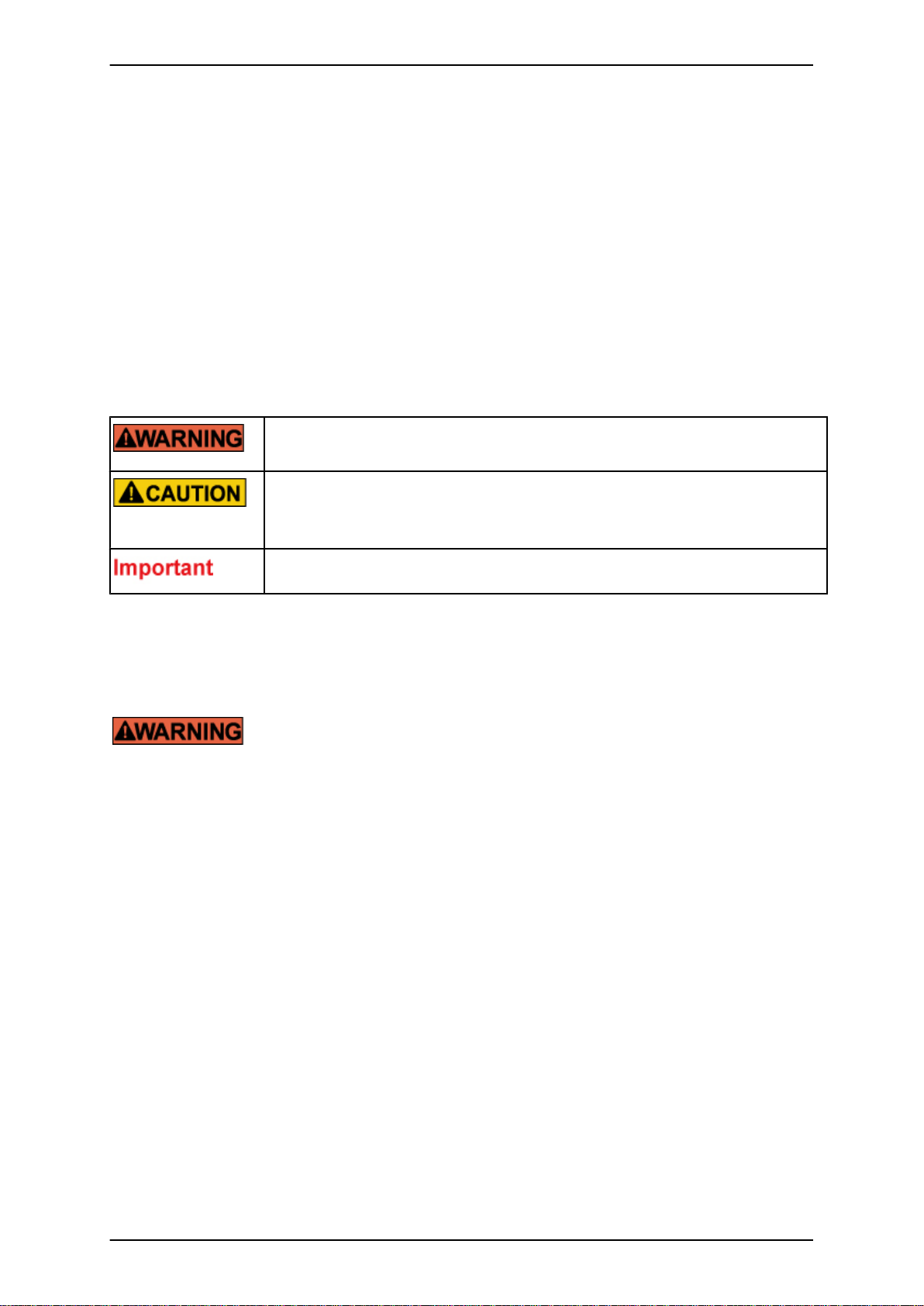
Warning labels
The following warning labels are affixed to this product. These labels are intended for the users of this product.
Never remove the warning labels.
viii C122-H004-07EN
Page 11
PRIMEQUEST 1000 Series Hardware Installation Manual
Preface
* The label is affixed at either location.
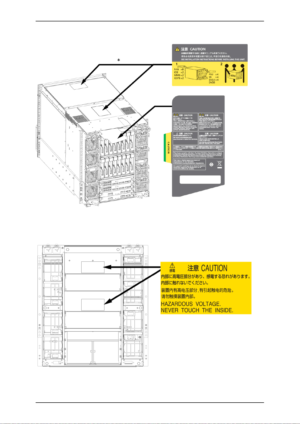
Warning label location (PRIMEQUEST 1800E2/1800E rear)
Warning label location (PRIMEQUEST 1800E2/1800E rear) (IOBs removed)
ix C122-H004-07EN
Page 12
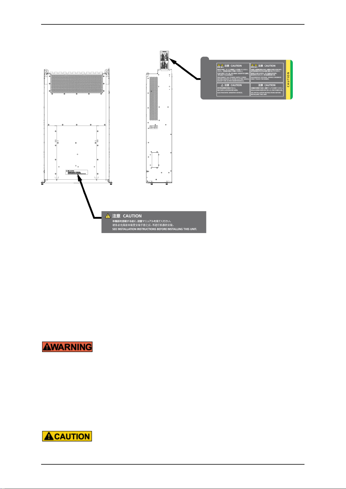
PRIMEQUEST 1000 Series Hardware Installation Manual
Preface
Warning label location (PCI_Box)
Notes on Handling the Product
Adding optional products
For stable operation of the PRIMEQUEST 1000 series server, use only a Fujitsu certified optional product as an
added option.
Note that the PRIMEQUEST 1000 series server is not guaranteed to operate with any optional product not certified
by Fujitsu.
Maintenance
Only Fujitsu certified service engineers should perform the following tasks on this
product and the options provided by Fujitsu. Customers must not perform these tasks
under any circumstances. Otherwise, electric shock, injury, or fire may result.
- Newly installing or moving equipment
- Removing the front, rear, and side covers
- Installing and removing built-in options
- Connecting and disconnecting external interface cables
- Maintenance (repair and periodic diagnosis and maintenance)
Only Fujitsu certified service engineers should perform the following tasks on this
product and the options provided by Fujitsu. Customers must not perform these tasks
under any circumstances. Otherwise, product failure may result.
x C122-H004-07EN
Page 13

PRIMEQUEST 1000 Series Hardware Installation Manual
Preface
- Unpacking an optional Fujitsu product, such as an optional adapter, delivered to
the customer
Modifying or recycling the product
Modifying this product or recycling a secondhand product by overhauling it without prior
approval may result in personal injury to users and/or bystanders or damage to the product
and/or other property.
Note on erasing data from hard disks when disposing of the product or transferring
it
Disposing of this product or transferring it as is may enable third parties to access the data on the hard disk and use
it for unforeseen purposes. To prevent the leakage of confidential information and important data, all of the data
on the hard disk must be erased before disposal or transfer of the product.
However, it can be difficult to completely erase all of the data from the hard disk. Simply initializing (reformatting)
the hard disk or deleting files on the operating system is insufficient to erase the data, even though the data appears
at a glance to have been erased. This type of operation only makes it impossible to access the data from the operating
system. Malicious third parties can restore this data.
If you save your confidential information or other important data on the hard disk, you should completely erase the
data, instead of simply carrying out the aforementioned operation, to prevent the data from being restored.
To prevent important data on the hard disk from being leaked when the product is disposed of or transferred, you
will need to take care to erase all the data recorded on the hard disk on your own responsibility.
Furthermore, if a software license agreement restricts the transfer of the software (operating system and application
software) on the hard disk in the server or other product to a third party, transferring the product without deleting
the software from the hard disk may violate the agreement. Adequate verification from this point of view is also
necessary.
Support and service
SupportDesk (available only in Japan, for a fee)
For stable system operation, we recommend concluding our SupportDesk agreement, which provides a maintenance
and operation support service. SupportDesk agreement customers receive a same-day response service for hardware
problems. They are eligible for regular checkups, remote notification of potential-failure predictions, and
information on system problems. Moreover, they can avail themselves of other services such as troubleshooting
support by phone for hardware and software problems, and access to operation support information from a dedicated
website for our customers. For details, see "Product support" on the SupportDesk homepage (http://jp.fujitsu.com/
solutions/support/sdk/index.html).
Product and service inquiries
For all product use and technical inquiries, contact the distributor where you purchased your product, or a Fujitsu
sales representative or systems engineer (SE). If you do not know the appropriate contact address for inquiries about
the PRIMEQUEST 1000 series, use the Fujitsu contact line.
Fujitsu contact line
We accept Web inquiries. For details, visit our website:
xi C122-H004-07EN
Page 14

PRIMEQUEST 1000 Series Hardware Installation Manual
Preface
https://www-s.fujitsu.com/global/contact/computing/PRMQST_feedback.html
Warranty
If a component failure occurs during the warranty period, we will repair it free of charge in accordance with the
terms of the warranty agreement. For details, see the warranty.
Before requesting a repair
If a problem occurs with the product, confirm the problem by referring to 11.2 Troubleshooting in the
PRIMEQUEST 1000 Series Administration Manual (C122-E108EN). If the error recurs, contact your sales
representative or a field engineer. Confirm the model name and serial number shown on the label affixed to the
right front of the device and report it. Also check any other required items beforehand according to 11.2
Troubleshooting in the PRIMEQUEST 1000 Series Administration Manual (C122-E108EN). The system settings
saved by the customer will be used during maintenance.
Revision History
Edition Date Revised location (type) (*) Description
01 2010-02-09 - -
02 2010-03-12 All pages
03 2010-08-20 All pages
04 2011-04-28 All pages
05 2011-05-31 All pages
06 2011-12-20 All pages
07 2012-06-19 Chapter 1 and Appendix A
Incorporated differences in Errata and
Addenda (C122-E119-01EN)
Incorporated differences in Errata and
Addenda (C122-E119-02EN to C122E119-10EN)
- Added items about 1800E2
- Incorporated differences in
Errata and Addenda (C122E119-11EN to C122E119-18EN)
Incorporated differences in Errata and
Addenda (C122-E119-19EN)
Incorporated differences in Errata and
Addenda (C122- E119-20EN to C122E119-24EN)
Added items about 19-inch racks
(models 2742/2737/2724/2642/
2624/2616)
* Chapter, section, and item numbers in the "Revised location" column refer to those in the latest edition of the
document. However, a number marked with an asterisk (*) denotes a chapter, section, or item in a previous edition
of the document.
This manual shall not be reproduced or copied without the permission of Fujitsu Limited.
Copyright 2010 - 2012 FUJITSU LIMITED
xii C122-H004-07EN
Page 15

PRIMEQUEST 1000 Series Hardware Installation Manual
Contents
Contents
CHAPTER 1 Installation Information .................................................................................................................. 1
1.1 Device Configuration Details .................................................................................................................... 2
1.2 Outline Drawings of the Devices ............................................................................................................... 3
1.2.1 PRIMEQUEST 1800E2/1800E outline drawings ................................................................................. 3
1.2.2 PCI_Box outline drawings ................................................................................................................... 4
1.3 Installation Specifications ......................................................................................................................... 6
1.3.1 PRIMEQUEST 1800E2 installation specifications ............................................................................... 6
1.3.2 PRIMEQUEST 1800E installation specifications ................................................................................. 7
1.3.3 PCI_Box installation specifications ...................................................................................................... 9
1.4 Installation Area ...................................................................................................................................... 11
1.5 Cooling and Exhaust Air Flows in the Devices ....................................................................................... 14
1.5.1 Cooling and exhaust air flows in the PRIMEQUEST 1800E2/1800E ................................................ 14
1.5.2 Cooling and exhaust air flows in the PCI_Box .................................................................................. 15
1.6 Installation Environment ......................................................................................................................... 16
1.6.1 Dust ................................................................................................................................................... 16
1.6.2 Corrosive gases ................................................................................................................................. 16
1.6.3 Seawater (salt damage) .................................................................................................................... 17
1.7 Security Actions ...................................................................................................................................... 18
CHAPTER 2 Connection Information ............................................................................................................... 19
2.1 Overview of Connections ........................................................................................................................ 20
2.1.1 Overview of Connections (PRIMEQUEST 1800E2) .......................................................................... 20
2.1.2 Overview of Connections (PRIMEQUEST 1800E) ............................................................................ 21
2.2 Signal Cable Connections ...................................................................................................................... 23
2.2.1 Basic interfaces and peripheral devices (PRIMEQUEST 1800E2) ................................................... 23
2.2.2 Basic interfaces and peripheral devices (PRIMEQUEST 1800E) ..................................................... 25
2.2.3 External interface connectors in detail .............................................................................................. 28
2.3 Power Cable Connections ...................................................................................................................... 32
2.3.1 Power cable connections of the PRIMEQUEST 1800E2/1800E ....................................................... 32
2.3.2 Power cable connections of the PCI_Box ......................................................................................... 34
2.4 Input Power Connection Specifications .................................................................................................. 38
2.4.1 PRIMEQUEST 1000 series main unit ................................................................................................ 38
2.4.2 PCI_Box ............................................................................................................................................ 38
2.4.3 Connections between the power distribution box and distribution panel .......................................... 39
2.5 Power Cable Connections under a Raised Floor (Except in Europe) ..................................................... 40
2.6 Shutoff Characteristic of the Customer's Distribution Panel (Only When Connected to the Power Distribution
Box) .................................................................................................................................................... 41
CHAPTER 3 Notes on Carrying In and Installing the Product ......................................................................... 43
3.1 Elevator Load Conditions ........................................................................................................................ 44
3.2 Earthquake Preparedness Measures ..................................................................................................... 45
APPENDIX A Racks ........................................................................................................................................ 47
A.1 Rack Mounting ....................................................................................................................................... 48
A.1.1 Arrangements for installation work .................................................................................................... 48
A.2 Rack Mounting Requirements ................................................................................................................ 51
A.2.1 Requirements for mounting in a Fujitsu 19-inch rack ........................................................................ 51
A.2.2 Requirements for mounting in a rack manufactured by another company ....................................... 57
A.3 Fujitsu 19-inch Racks ............................................................................................................................. 60
A.3.1 Types of 19-inch rack ....................................................................................................................... 60
A.3.2 Outline drawings of 19-inch racks ..................................................................................................... 62
A.3.3 Bottom view drawings of 19-inch racks ............................................................................................. 75
APPENDIX B UPC Interface ............................................................................................................................ 81
B.1 Overview ................................................................................................................................................ 82
B.2 Signal Cable ........................................................................................................................................... 83
B.3 Connection of Main Unit and CVCF and Signal Line Definitions ............................................................ 84
xiii C122-H004-07EN
Page 16

PRIMEQUEST 1000 Series Hardware Installation Manual
Contents
B.4 Cable Connector .................................................................................................................................... 86
Index ................................................................................................................................................................. 87
xiv C122-H004-07EN
Page 17

PRIMEQUEST 1000 Series Hardware Installation Manual
Figures
Figures
Warning label location (PRIMEQUEST 1800E2/1800E rear) ............................................................................. ix
Warning label location (PRIMEQUEST 1800E2/1800E rear) (IOBs removed) .................................................. ix
Warning label location (PCI_Box) ....................................................................................................................... x
FIGURE 1.1 PRIMEQUEST 1800E2/1800E (front view) ................................................................................... 3
FIGURE 1.2 PRIMEQUEST 1800E2/1800E (rear view) .................................................................................... 3
FIGURE 1.3 PRIMEQUEST 1800E2/1800E (top view) ..................................................................................... 4
FIGURE 1.4 PRIMEQUEST 1800E2/1800E (right side view) ............................................................................ 4
FIGURE 1.5 PCI_Box front view ........................................................................................................................ 5
FIGURE 1.6 PCI_Box rear view ......................................................................................................................... 5
FIGURE 1.7 PCI_Box top view .......................................................................................................................... 5
FIGURE 1.8 PCI_Box right side view ................................................................................................................ 5
FIGURE 1.9 Service area with the 19-inch rack model 1740 (19R-174xx) installed ....................................... 11
FIGURE 1.10 Service area with the 19-inch rack model 1640 (19R-164xx) installed ..................................... 12
FIGURE 1.11 Service area with the 19-inch rack model 1624 (19R-162xx) installed ..................................... 13
FIGURE 1.12 Cooling and exhaust air flows in the PRIMEQUEST 1800E2/1800E ........................................ 14
FIGURE 1.13 Cooling and exhaust air flows in the PCI_Box .......................................................................... 15
FIGURE 2.1 Overview of device connections (PRIMEQUEST 1800E2) ......................................................... 20
FIGURE 2.2 Overview of device connections (PRIMEQUEST 1800E) ........................................................... 21
FIGURE 2.3 Interface cable connections (for the basic interfaces and peripheral devices) (PRIMEQUEST
1800E2) ................................................................................................................................................. 23
FIGURE 2.4 Interface cable connections (for the basic interfaces and peripheral devices) (PRIMEQUEST 1800E)
................................................................................................................................................................ 26
FIGURE 2.5 External interface connectors in the PRIMEQUEST 1800E2/1800E main unit (front view) ........ 28
FIGURE 2.6 External interface connectors in the PRIMEQUEST 1800E2/1800E main unit (rear view) ......... 29
FIGURE 2.7 MMB external interfaces in detail ................................................................................................ 29
FIGURE 2.8 IOB external interfaces in detail .................................................................................................. 30
FIGURE 2.9 GSPB external interfaces in detail ............................................................................................... 30
FIGURE 2.10 PCI_Box external interfaces in detail ........................................................................................ 31
FIGURE 2.11 Standard configuration (primary power feed, no redundant power supply) ............................... 32
FIGURE 2.12 Redundant power supply configuration (primary power feed, redundant power supply) .......... 33
FIGURE 2.13 Dual power feed configuration ................................................................................................... 33
FIGURE 2.14 200 to 240 V standard configuration (primary power feed, no redundant power supply) .......... 34
FIGURE 2.15 200 to 240 V redundant power supply configuration (primary power feed, redundant power supply)
................................................................................................................................................................ 35
FIGURE 2.16 200 to 240 V dual power feed configuration .............................................................................. 36
FIGURE 2.17 100 to 120 V configuration (primary power feed, no redundant power supply) ......................... 37
FIGURE 2.18 100 to 120 V redundant power supply configuration (primary power feed, redundant power supply)
................................................................................................................................................................ 37
FIGURE 2.19 Power cable connections under a raised floor (except in Europe) ............................................ 40
FIGURE 2.20 Distribution panel breaker characteristics ................................................................................. 42
FIGURE A.1 Caution on rack mounting ........................................................................................................... 51
FIGURE A.2 Rack mounting requirements (PRIMEQUEST 1800E2/1800E) .................................................. 54
FIGURE A.3 Cable holder locations ................................................................................................................ 55
FIGURE A.4 Removing a cable holder (Model 1740) ...................................................................................... 56
FIGURE A.5 Removing a cable holder (Model 1640/Model 1624) .................................................................. 57
FIGURE A.6 Conditions of rack depth ............................................................................................................. 58
FIGURE A.7 Conditions regarding rack posts ................................................................................................. 59
FIGURE A.8 Outline drawing of the 19-inch rack Model 1740 (base/with stabilizer) ....................................... 63
FIGURE A.9 Outline drawing of the 19-inch rack Model 1740 (base/without stabilizer) .................................. 64
FIGURE A.10 Outline drawing of the 19-inch rack Model 1740 (expansion/with stabilizer) ............................ 66
FIGURE A.11 Outline drawing of the 19-inch rack Model 1740 (expansion/without stabilizer) ....................... 67
FIGURE A.12 Outline drawing of the 19-inch rack Model 1640 (base/with stabilizer) ..................................... 68
FIGURE A.13 Outline drawing of the 19-inch rack Model 1640 (base/without stabilizer) ................................ 69
FIGURE A.14 Outline drawing of the 19-inch rack Model 1640 (expansion/with stabilizer) ............................ 71
FIGURE A.15 Outline drawing of the 19-inch rack Model 1640 (expansion/without stabilizer) ....................... 72
FIGURE A.16 Outline drawing of the 19-inch rack Model 1624 (base/with stabilizer) ..................................... 73
xv C122-H004-07EN
Page 18

PRIMEQUEST 1000 Series Hardware Installation Manual
Figures
FIGURE A.17 Outline drawing of the 19-inch rack Model 1624 (base/without stabilizer) ................................ 73
FIGURE A.18 Outline drawing of the 19-inch rack Model 1624 (expansion/with stabilizer) ............................ 74
FIGURE A.19 Outline drawing of the 19-inch rack Model 1624 (expansion/without stabilizer) ....................... 75
FIGURE A.20 Bottom view drawing of the (standard) 19-inch rack ................................................................. 76
FIGURE A.21 Bottom view drawing of the (slim) 19-inch rack ........................................................................ 77
FIGURE A.22 Bottom view drawing of the rack equipped with the pullout stabilizer (standard type only) ....
78
FIGURE A.23 Bottom view drawing of connected 19-inch racks (standard) ................................................... 79
FIGURE A.24 Bottom view drawing of connected 19-inch racks (slim) ........................................................... 79
FIGURE B.1 UPC port locations (PRIMEQUEST 1800E2/1800E) .................................................................. 82
FIGURE B.2 Connection of the main unit and CVCF ...................................................................................... 84
FIGURE B.3 Correspondence between UPC interface and signal cable pins ................................................. 86
xvi C122-H004-07EN
Page 19

PRIMEQUEST 1000 Series Hardware Installation Manual
Tables
Tables
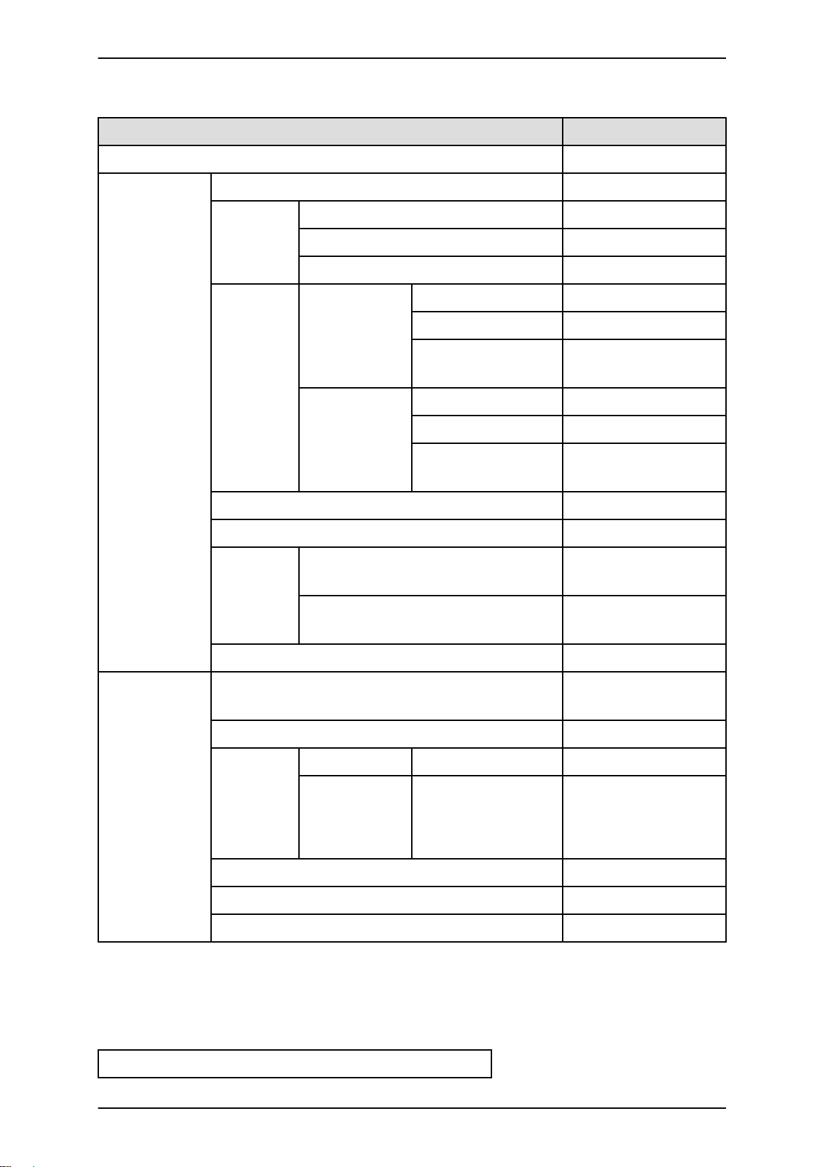
TABLE 1.1 Device names and configuration details .......................................................................................... 2
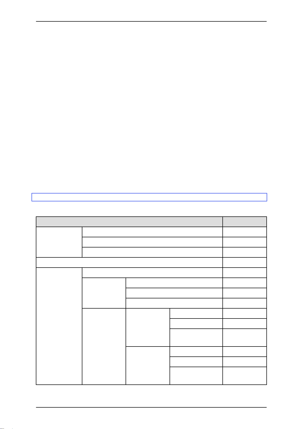
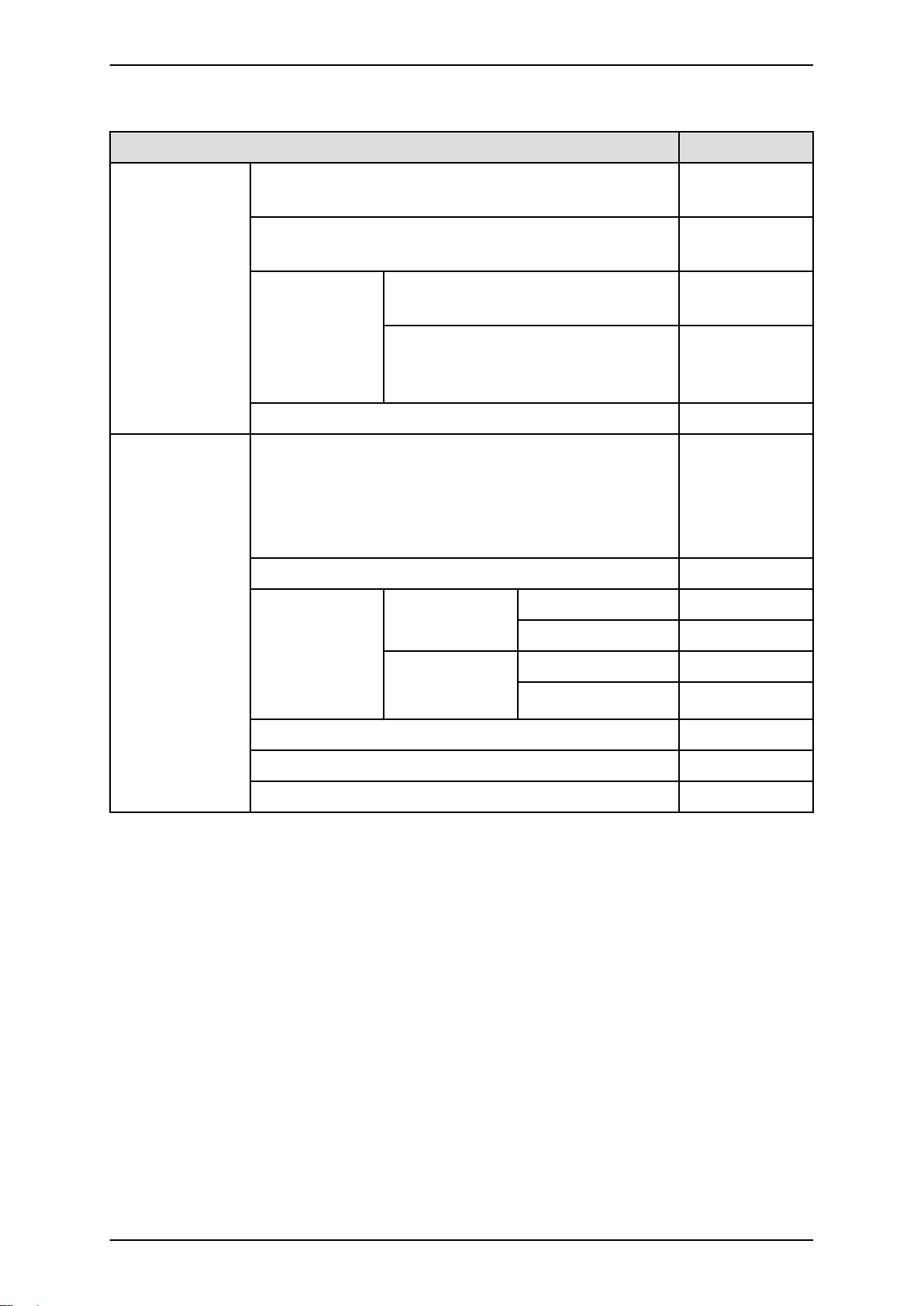
TABLE 1.2 PRIMEQUEST 1800E2 installation specifications ........................................................................... 6
TABLE 1.3 PRIMEQUEST 1800E installation specifications ............................................................................. 7
TABLE 1.4 PCI_Box installation specifications .................................................................................................. 9
TABLE 1.5 Tolerable limits for corrosive gases ............................................................................................... 16
TABLE 2.1 Notes on device connections (PRIMEQUEST 1800E2) ................................................................ 20
TABLE 2.2 Notes on device connections (PRIMEQUEST 1800E) .................................................................. 22
TABLE 2.3 Cables (for the basic interfaces and peripheral devices) (PRIMEQUEST 1800E2) ...................... 24
TABLE 2.4 Cables (for the basic interfaces and peripheral devices) (PRIMEQUEST 1800E) ........................ 26
TABLE 2.5 Power cable specifications of the PRIMEQUEST 1000 series main unit ...................................... 38
TABLE 2.6 Power cable specifications of the PCI_Box ................................................................................... 38
TABLE 2.7 Specifications of the power cable between the power distribution box and distribution panel ....
39
TABLE 2.8 Breaker characteristics for the customer's distribution panel ........................................................ 41
TABLE 3.1 Elevator load conditions ................................................................................................................ 44
TABLE A.1 Arrangements for installation work ................................................................................................ 48
TABLE A.2 Recommended racks for mounting ............................................................................................... 52
TABLE A.3 PRIMEQUEST 1000 series external dimensions* ......................................................................... 52
TABLE A.4 Rack mounting requirements ........................................................................................................ 52
TABLE A.5 Types of 19-inch rack .................................................................................................................... 60
TABLE B.1 Signal line definitions .................................................................................................................... 84
xvii C122-H004-07EN
Page 20

PRIMEQUEST 1000 Series Hardware Installation Manual
Tables
xviii C122-H004-07EN
Page 21

CHAPTER 1 Installation Information
This chapter provides various useful information on PRIMEQUEST
1000 series installation. The information includes device configuration
details, device outline drawings, installation specifications, and
various layout diagrams.
1.1 Device Configuration Details ........................................ 2
1.2 Outline Drawings of the Devices .................................. 3
1.3 Installation Specifications ............................................. 6
1.4 Installation Area ......................................................... 11
1.5 Cooling and Exhaust Air Flows in the Devices ........... 14
1.6 Installation Environment ............................................. 16
1.7 Security Actions ......................................................... 18
Page 22

PRIMEQUEST 1000 Series Hardware Installation Manual
CHAPTER 1 Installation Information
1.1 Device Configuration Details
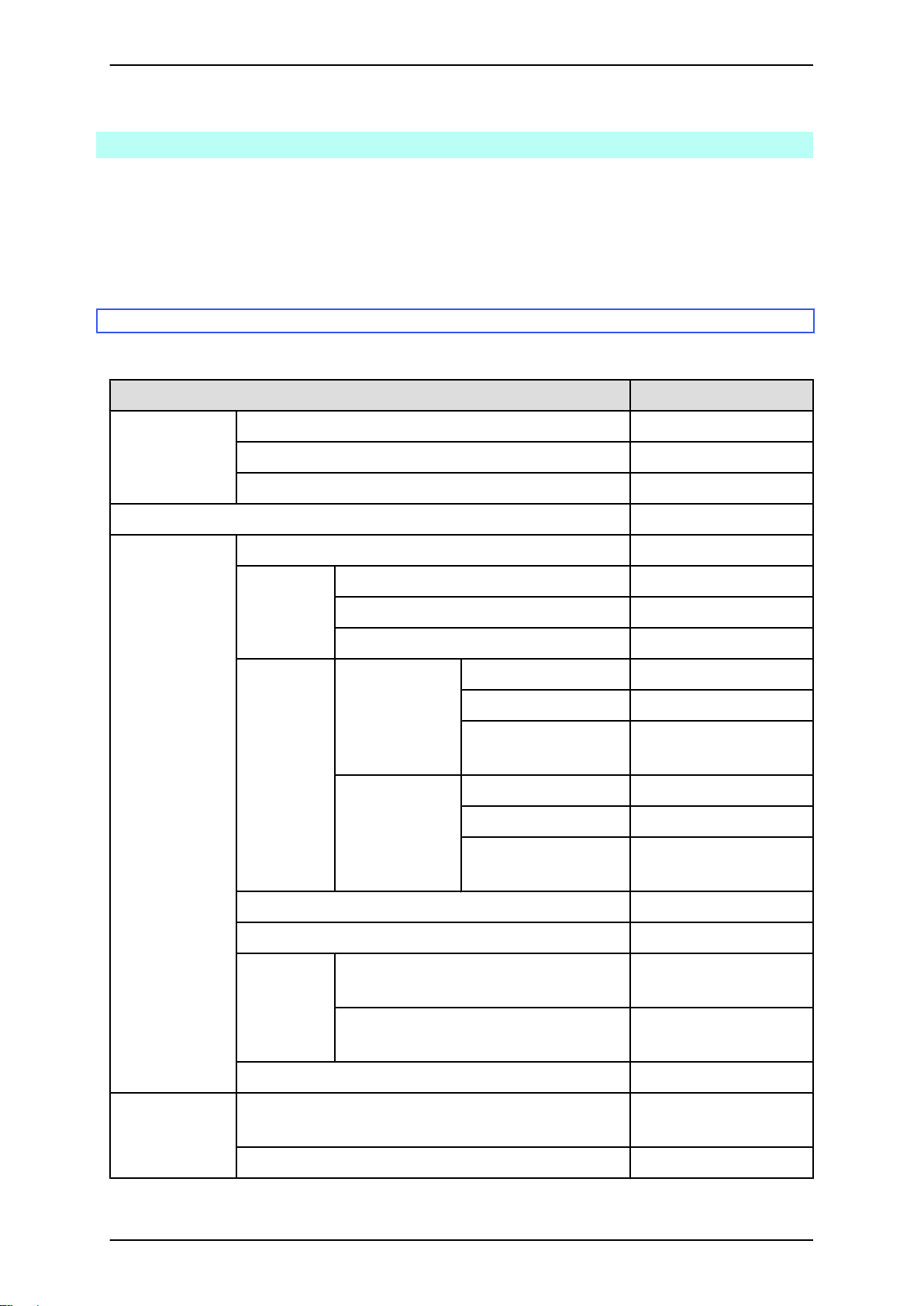
TABLE 1.1 Device names and configuration details lists device names and configuration details.
TABLE 1.1 Device names and configuration details
Device name Description of configuration Size (height)
PRIMEQUEST 1800E2/1800E Can accommodate up to 4 system boards (up to 8
CPUs) and up to 2 IO boards.
PCI_Box Expands the number of PCI Express slots.
Up to 2 units can be connected to the
PRIMEQUEST 1800E2/1800E.
The PCI Box has 12 PCI Express slots.
Remarks
All the devices listed in TABLE 1.1 Device names and configuration details can be mounted in EIA-compliant 19inch racks. For details on the 19-inch racks, see APPENDIX A Racks or contact the distributor where you purchased
your product, or your sales representative.
12U
4U
2 C122-H004-07EN
Page 23
PRIMEQUEST 1000 Series Hardware Installation Manual
CHAPTER 1 Installation Information
1.2 Outline Drawings of the Devices
This section provides outline drawings of each device.
- 1.2.1 PRIMEQUEST 1800E2/1800E outline drawings
- 1.2.2 PCI_Box outline drawings
1.2.1 PRIMEQUEST 1800E2/1800E outline drawings
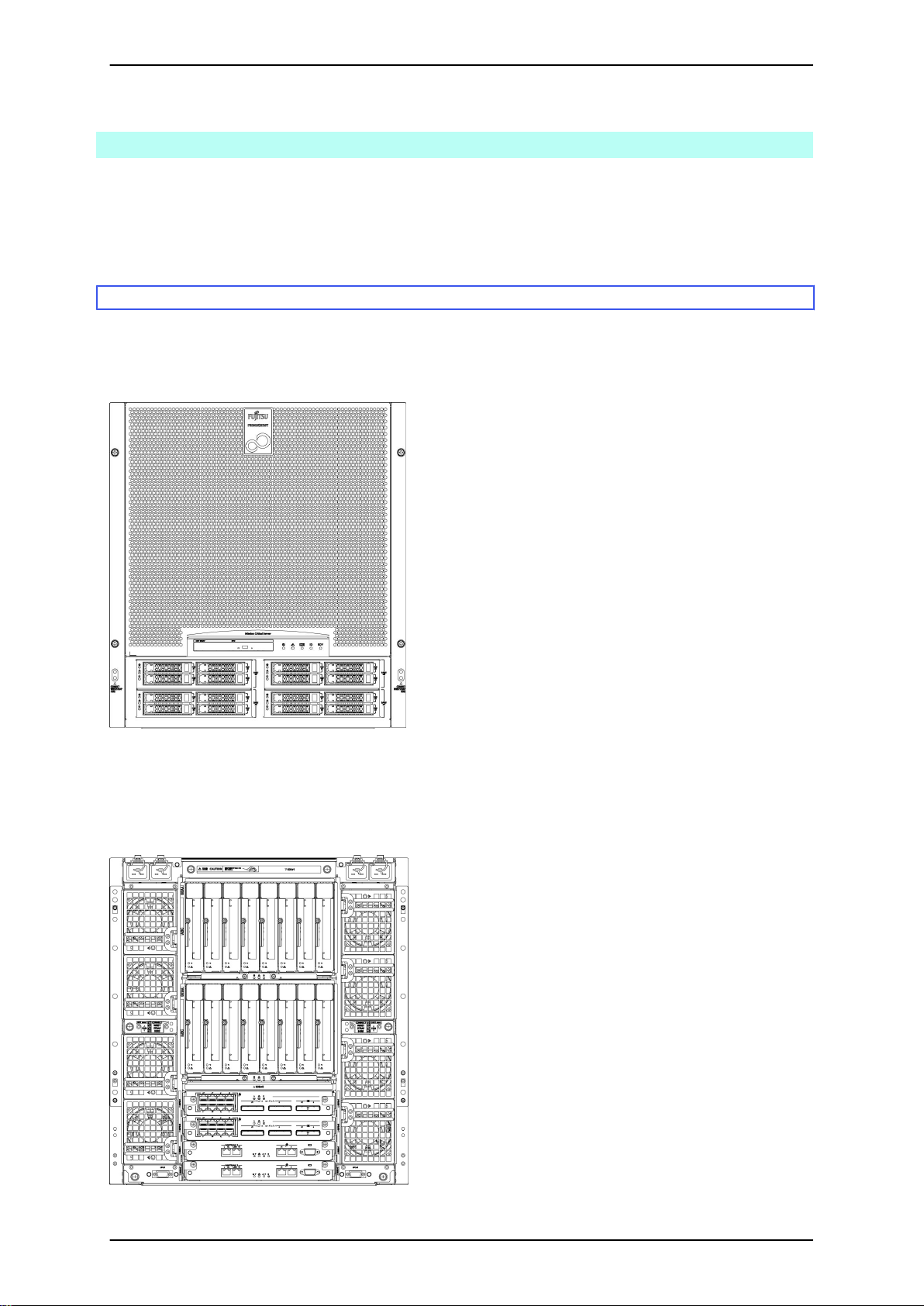
This section includes outline drawings of the PRIMEQUEST 1800E2/1800E (front, rear, top, and right side views).
PRIMEQUEST 1800E2/1800E (front view)
FIGURE 1.1 PRIMEQUEST 1800E2/1800E (front view)
PRIMEQUEST 1800E2/1800E (rear view)
FIGURE 1.2 PRIMEQUEST 1800E2/1800E (rear view)
3 C122-H004-07EN
Page 24
PRIMEQUEST 1000 Series Hardware Installation Manual
CHAPTER 1 Installation Information
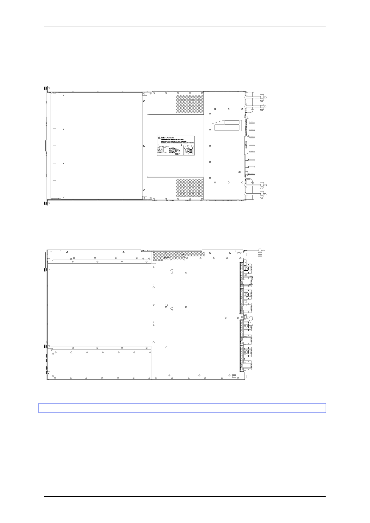
PRIMEQUEST 1800E2/1800E (top view)
FIGURE 1.3 PRIMEQUEST 1800E2/1800E (top view)
PRIMEQUEST 1800E2/1800E (right side view)
FIGURE 1.4 PRIMEQUEST 1800E2/1800E (right side view)
1.2.2 PCI_Box outline drawings
This section includes outline drawings of the PCI_Box (front, rear, top, and right side views).
PCI_Box front view
4 C122-H004-07EN
Page 25

PRIMEQUEST 1000 Series Hardware Installation Manual
CHAPTER 1 Installation Information
FIGURE 1.5 PCI_Box front view
PCI_Box rear view
FIGURE 1.6 PCI_Box rear view
PCI_Box top view
FIGURE 1.7 PCI_Box top view
PCI_Box right side view
FIGURE 1.8 PCI_Box right side view
5 C122-H004-07EN
Page 26
PRIMEQUEST 1000 Series Hardware Installation Manual
CHAPTER 1 Installation Information
1.3 Installation Specifications
This section lists the installation specifications of each device.
- 1.3.1 PRIMEQUEST 1800E2 installation specifications
- 1.3.2 PRIMEQUEST 1800E installation specifications
- 1.3.3 PCI_Box installation specifications
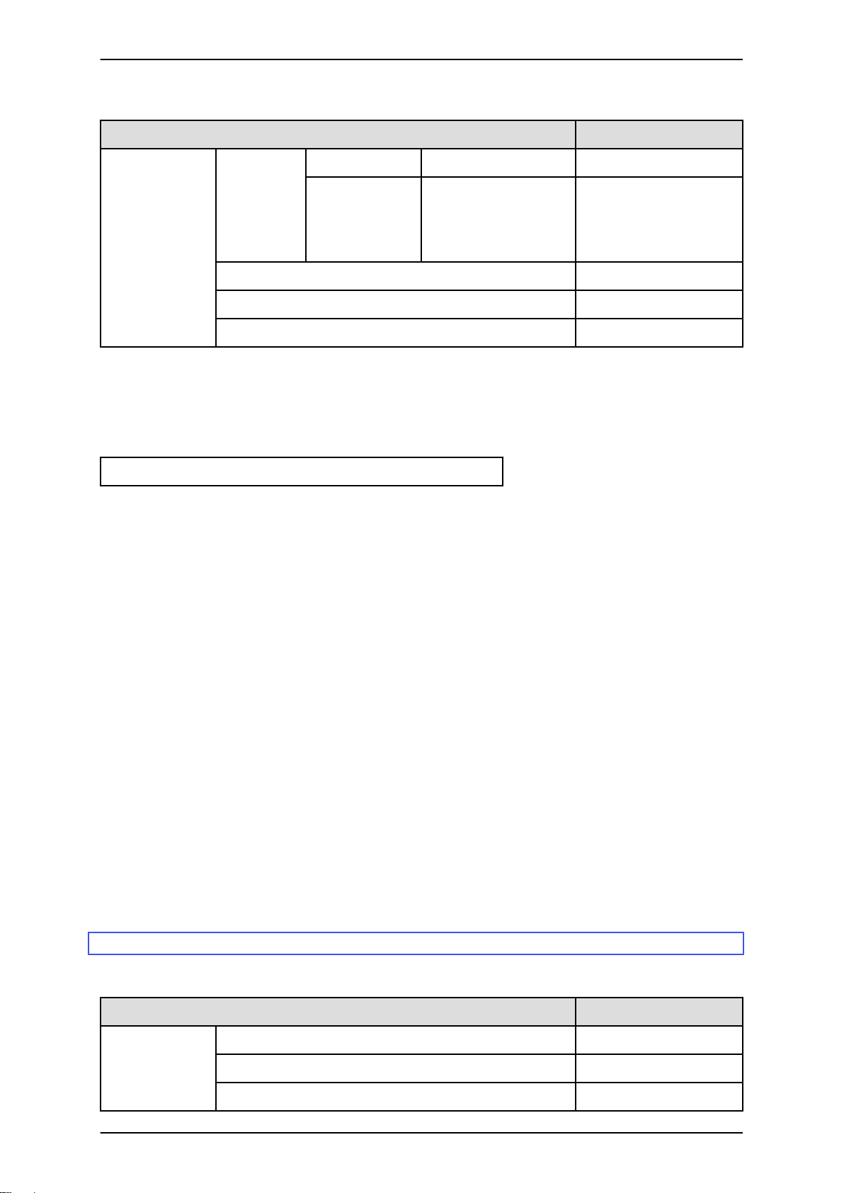
1.3.1 PRIMEQUEST 1800E2 installation specifications
TABLE 1.2 PRIMEQUEST 1800E2 installation specifications
Item Description
External
dimensions
[mm (in.)]
Weight [kg (lb)] (*2) 150 (330)
Air conditioning
requirements
Width 482 (18.98)
Depth (*1) 800 (31.50)
Height 530 (20.87)
Maximum heat output [kJ/h (BTU/h)] 14,400 (13,649)
Exhaust air
flow [m3/min
(ft3/min)] (*3)
Temperature
and humidity
requirements
(*4)
FAN at low speed (Low) 14 (494)
FAN at normal speed (Normal) 21 (742)
FAN at high speed (High) 24 (848)
Operating Temperature [°C (°F)] (*5)
Humidity [%RH] 20 to 80
Maximum wet-bulb
temperature [°C (°F)]
Non-operating (*6) Temperature [°C (°F)] 0 to 50 (32 to 122)
Humidity [%RH] 8 to 80
Maximum wet-bulb
temperature [°C (°F)]
29 (84.2)
29 (84.2)
Power
requirements
Noise [dB] (*7) (*8) 61
Acoustic power level [B] (*8) 7.8
Allowable
vibration [m/
s2 (gal)]
Allowable dust concentration [mg/m3] 0.15
Input voltage and number of phases 200 to 240 VAC ±10%
Frequency and fluctuation range 50/60 Hz +2/-4%
Operating (including standby state) 4.0 (400) (synthetic seismic
waves)
Non-operating (*9) 10.0 (1000) (synthetic
seismic waves)
1φ
6 C122-H004-07EN
Page 27
PRIMEQUEST 1000 Series Hardware Installation Manual
CHAPTER 1 Installation Information
Item Description
Maximum
power
Operating Input voltage: 200 V 4.00 kW / 4.21 kVA
Standby Input voltage: 200 V 95 W / 126 VA
consumption/
apparent
power
Power factor (*10) 0.95 or more
Rush current [A] (Inrush time) (*11) 20 or less
Leakage current [mA] (*12) 3.5 or less
*1 The dimensions do not include protrusions.
*2 The values are for the device with all options installed.
However, the values do not include the weight of mounted rack-mount rails (7 kg) and cables.
You can use the following formula to calculate the weight of the device based on its configuration:
Equipment weight = 86 + (11 x A) + (8 x B) + (2 x C) [kg]
- A = Number of mounted SBs (1 to 4)
- B = Number of mounted IO Units (1 or 2)
- C = Number of mounted expansion power supply units (0 to 2)
*3 If the intake air temperature is high (but within the normal temperature range), the fan enters high-speed mode
even when operation is normal.
*4 Condensation is not permitted.
*5 The temperature requirements depend on the altitude at the installation site.
- Installation at 0 to 500 m (0 to 1640 ft.) above sea level: 5 to 35°C (41 to 95.0°F)
- Installation at 500 to 1000 m (1640 to 3281 ft.) above sea level: 5 to 34°C (41 to 93.2°F)
- Installation at 1000 to 1500 m (3281 to 4921 ft.) above sea level: 5 to 33°C (41 to 91.4°F)
- Installation at 1500 to 3000 m (4921 to 9843 ft.) above sea level: 5 to 30°C (41 to 86.0°F)
The altitude specifications for the installation site include an allowable margin of error of ±100 m.
*6 "Non-operating" refers to the condition where a device has been disconnected from the power supply and stored.
*7 The actual acoustic noise level depends on the listener's location and the rack mounting conditions.
*8 The noise and acoustic power levels depend on the ambient temperature.
*9 "Non-operating" refers to the installed device in the power-off state.
*10 This is the value during operation.
*11 This value is for a single input cable.
*12 This value is for a single device.
1.3.2 PRIMEQUEST 1800E installation specifications
TABLE 1.3 PRIMEQUEST 1800E installation specifications
Item Description
External
dimensions
[mm (in.)]
Width 482 (18.98)
Depth (*1) 800 (31.50)
Height 530 (20.87)
7 C122-H004-07EN
Page 28
PRIMEQUEST 1000 Series Hardware Installation Manual
CHAPTER 1 Installation Information
Item Description
Weight [kg (lb)] (*2) 150 (330)
Air conditioning
requirements
Maximum heat output [kJ/h (BTU/h)] 14,400 (13,649)
Exhaust air
flow [m3/min
FAN at low speed (Low) 14 (494)
FAN at normal speed (Normal) 21 (742)
(ft3/min)] (*3)
FAN at high speed (High) 24 (848)
Temperature
and humidity
Operating Temperature [°C (°F)] (*5)
Humidity [%RH] 20 to 80
requirements
(*4)
Maximum wet-bulb
29 (84.2)
temperature [°C (°F)]
Non-operating (*6) Temperature [°C (°F)] 0 to 50 (32 to 122)
Humidity [%RH] 8 to 80
Maximum wet-bulb
29 (84.2)
temperature [°C (°F)]
Noise [dB] (*7) (*8) 61
Acoustic power level [B] (*8) 7.8
Allowable
vibration [m/
s2 (gal)]
Operating (including standby state) 4.0 (400) (synthetic seismic
waves)
Non-operating (*9) 10.0 (1000) (synthetic
seismic waves)
Allowable dust concentration [mg/m3] 0.15
Power
requirements
Input voltage and number of phases 200 to 240 VAC ±10%
Single phase
Frequency and fluctuation range 50/60 Hz +2/-4%
Maximum
power
Operating Input voltage: 200 V 4.00 kW / 4.21 kVA
Standby Input voltage: 200 V 95 W / 126 VA
consumption/
apparent
power
Power factor (*10) 0.95 or more
Rush current [A] (Inrush time) (*11) 20 or less
Leakage current [mA] (*12) 3.5 or less
*1 The dimensions do not include protrusions.
*2 The values are for the device with all options installed.
However, the values do not include the weight of mounted rack-mount rails (7 kg) and cables.
You can use the following formula to calculate the weight of the device based on its configuration:
Equipment weight = 86 + (11 x A) + (8 x B) + (2 x C)
8 C122-H004-07EN
Page 29
PRIMEQUEST 1000 Series Hardware Installation Manual
CHAPTER 1 Installation Information
- A = Number of mounted SBs (1 to 4)
- B = Number of mounted IO Units (1 or 2)
- C = Number of mounted expansion power supply units (0 to 2)
*3 If the intake air temperature is high (but within the normal temperature range), the fan enters high-speed mode
even when operation is normal.
*4 Condensation is not permitted.
*5 The temperature requirements depend on the altitude at the installation site.
- Installation at 0 to 500 m (0 to 1640 ft.) above sea level: 5 to 35°C (41 to 95.0°F)
- Installation at 500 to 1000 m (1640 to 3281 ft.) above sea level: 5 to 34°C (41 to 93.2°F)
- Installation at 1000 to 1500 m (3281 to 4921 ft.) above sea level: 5 to 33°C (41 to 91.4°F)
- Installation at 1500 to 3000 m (4921 to 9843 ft.) above sea level: 5 to 30°C (41 to 86.0°F)
The altitude specifications for the installation site include an allowable margin of error of ±100 m.
*6 "Non-operating" refers to the condition where a device has been disconnected from the power supply and stored.
*7 The actual acoustic noise level depends on the listener's location and the rack mounting conditions.
*8 The noise and acoustic power levels depend on the ambient temperature.
*9 "Non-operating" refers to the installed device in the power-off state.
*10 This is the value during operation.
*11 This value is for a single input cable.
*12 This value is for a single device.
1.3.3 PCI_Box installation specifications
TABLE 1.4 PCI_Box installation specifications
Item Description
External dimensions
[mm (in.)]
Weight [kg (lb)] (*2) 35 (77)
Air conditioning
requirements
Width 482 (18.98)
Depth (*1) 740 (29.13)
Height 175 (6.89)
Maximum heat output [kJ/h (BTU/h)] 1,656 (1,570)
Exhaust air flow
[m3/min (ft3/min)]
FAN at low speed (Low) 3 (106)
FAN at normal speed (Normal) 4 (141)
(*3)
FAN at high speed (High) 5 (177)
Temperature and
humidity
Operating Temperature [°C (°F)] (*5)
Humidity [%RH] 20 to 80
requirements (*4)
Maximum wet-bulb
29 (84.2)
temperature [°C (°F)]
Non-operating (*6) Temperature [°C (°F)] 0 to 50 (32 to 122)
Humidity [%RH] 8 to 80
Maximum wet-bulb
29 (84.2)
temperature [°C (°F)]
9 C122-H004-07EN
Page 30
PRIMEQUEST 1000 Series Hardware Installation Manual
CHAPTER 1 Installation Information
Item Description
Noise [dB] (Included in main
Acoustic power level [B] (Included in main
unit specifications)
unit specifications)
Allowable vibration
[m/s2 (gal)]
Operating (including standby state) 4.0 (400) (synthetic
seismic waves)
Non-operating (*6) 10.0
(1000) (synthetic
seismic waves)
Allowable dust concentration [mg/m3] 0.15
Power requirements Input voltage and number of phases 200 to 240
VAC ±10%
100 to 120
VAC ±10%
1φ
Frequency and fluctuation range 50/60 Hz +2/-4%
Maximum power
consumption/
Operating Input voltage: 200 V 450 W / 475 VA
Input voltage: 100 V 460 W / 485 VA
apparent power
Standby
Input voltage: 200 V 10 W / 40 VA
Input voltage: 100 V 10 W / 35 VA
Power factor (*7) 0.95 or more
Rush current [A] (Inrush time) (*8) 25 or less
Leakage current [mA] (*9) 3.5 or less
*1 The dimensions do not include protrusions.
*2 The values are for the device with all options installed.
However, the values do not include the weight of mounted rack-mount rails (7 kg) and cables.
*3 If the intake air temperature is high (but within the normal temperature range), the fan enters high-speed mode
even when operation is normal.
*4 Condensation is not permitted.
*5 The temperature requirements depend on the altitude at the installation site.
- Installation at 0 to 500 m (0 to 1640 ft.) above sea level: 5 to 35°C (41 to 95.0°F)
- Installation at 500 to 1000 m (1640 to 3281 ft.) above sea level: 5 to 34°C (41 to 93.2°F)
- Installation at 1000 to 1500 m (3281 to 4921 ft.) above sea level: 5 to 33°C (41 to 91.4°F)
- Installation at 1500 to 3000 m (4921 to 9843 ft.) above sea level: 5 to 30°C (41 to 86.0°F)
The altitude specifications for the installation site include an allowable margin of error of ±100 m.
*6 "Non-operating" refers to the condition where a device has been disconnected from the power supply and stored.
*7 This is the value during operation.
*8 This value is for a single input cable.
*9 This value is for a single device.
10 C122-H004-07EN
Page 31

PRIMEQUEST 1000 Series Hardware Installation Manual
CHAPTER 1 Installation Information
1.4 Installation Area
This section shows the installation area and service areas of the PRIMEQUEST 1000 series and PCI_Box. The
diagrams assume that the devices are mounted in Fujitsu 19-inch racks.
The actual installation and service areas may vary depending on the 19-inch rack with the mounted device. For
details on the 19-inch racks, see APPENDIX A Racks or contact the distributor where you purchased your product,
or your sales representative.
No. Description
(1) Service area
(2) Front of the device
FIGURE 1.9 Service area with the 19-inch rack model 1740 (19R-174xx) installed
11 C122-H004-07EN
Page 32

PRIMEQUEST 1000 Series Hardware Installation Manual
CHAPTER 1 Installation Information
No. Description
(1) Service area
(2) Front of the device
FIGURE 1.10 Service area with the 19-inch rack model 1640 (19R-164xx) installed
12 C122-H004-07EN
Page 33

PRIMEQUEST 1000 Series Hardware Installation Manual
CHAPTER 1 Installation Information
No. Description
(1) Service area
(2) Front of the device
FIGURE 1.11 Service area with the 19-inch rack model 1624 (19R-162xx) installed
13 C122-H004-07EN
Page 34

PRIMEQUEST 1000 Series Hardware Installation Manual
CHAPTER 1 Installation Information
1.5 Cooling and Exhaust Air Flows in the Devices
This section shows the cooling and exhaust air flows in each device.
- 1.5.1 Cooling and exhaust air flows in the PRIMEQUEST 1800E2/1800E
- 1.5.2 Cooling and exhaust air flows in the PCI_Box
Note
An important consideration in the planning for installation of the device is the cooling and exhaust air flows. If the
device is installed without regard to these air flows, the device may take in exhaust air from another device, or vice
versa. The exhaust air would likely have an effect on that device. Such an installation runs the risk of continuous
output of intake air temperature alarms from this device or another device that monitors the intake air temperature.
1.5.1 Cooling and exhaust air flows in the PRIMEQUEST 1800E2/1800E
No. Description
(1) Air intake
(2) Exhaust air
(3) Exhaust vent
FIGURE 1.12 Cooling and exhaust air flows in the PRIMEQUEST 1800E2/1800E
14 C122-H004-07EN
Page 35

PRIMEQUEST 1000 Series Hardware Installation Manual
CHAPTER 1 Installation Information
1.5.2 Cooling and exhaust air flows in the PCI_Box
No. Description
(1) Air intake
(2) Exhaust air
(3) Exhaust vent
FIGURE 1.13 Cooling and exhaust air flows in the PCI_Box
15 C122-H004-07EN
Page 36

PRIMEQUEST 1000 Series Hardware Installation Manual
CHAPTER 1 Installation Information
1.6 Installation Environment
This section describes matters regarding the installation environment of equipment.
- 1.6.1 Dust
- 1.6.2 Corrosive gases
- 1.6.3 Seawater (salt damage)
1.6.1 Dust
Airborne dust
Ensure that airborne dust does not exceed 0.15 mg/m3 in computer rooms. Most computers are designed to withstand
this level of airborne dust. This is the same as the permissible level for airborne dust in a general office and should
be easily attainable in a computer room where there is little inflow of outside air containing airborne dust and
cigarette smoke.
Removing dust
Airborne dust is collected by air filters in the air conditioner. The computer room must be periodically cleaned to
remove dust on and under the floor. Cleaning is required in the following situations:
- When the construction of the computer room has just been completed, and it is ready to house equipment.
- When the computer room has been repaired.
- When equipment already in position in the computer room has been relocated.
1.6.2 Corrosive gases
Corrosive gases must be removed and kept out by using appropriate air cleaning facilities. Maintaining positive
pressure in the computer room with filtered air will serve as a safeguard against the entry of corrosive gases from
an outside source. TABLE 1.5 Tolerable limits for corrosive gases lists the tolerable limits for different kinds of
corrosive gases.
TABLE 1.5 Tolerable limits for corrosive gases
Gas name Tolerable limit
Hydrogen sulfide (H2S)
Sulfur dioxide (sulfur oxide) (SO2)
Hydrogen chloride (HCI) 6.6 ppb and under
Chlorine (CI2)
Hydrogen fluoride (HF) 3.6 ppb and under
Nitrogen dioxide (nitrogen oxide) (NO2)
Ammonia (NH3)
Ozone (O3)
7.1 ppb and under
37 ppb and under
3.4 ppb and under
52 ppb and under
420 ppb and under
5 ppb and under
Oil vapor 0.2 mg/m3 and under
16 C122-H004-07EN
Page 37

PRIMEQUEST 1000 Series Hardware Installation Manual
CHAPTER 1 Installation Information
1.6.3 Seawater (salt damage)
The air in the vicinity of coastal areas contains large amounts of airborne sea salt particles. If these particles remain
inside computers, substances are formed by a condensation reaction of chemicals. These substances and the
humidity lead to insulation failure and the corrosion and deterioration of components and materials. Therefore,
computers should be installed in locations at a distance from coastal areas.
The following outlines installation criteria for preventing salt water damage due to airborne sea salt particles.
Criteria: The installation site shall not be within 0.5 km of the ocean or coastal areas (unless the computer room
uses air conditioners to filter out airborne sea salt particles from outside air).
17 C122-H004-07EN
Page 38

PRIMEQUEST 1000 Series Hardware Installation Manual
CHAPTER 1 Installation Information
1.7 Security Actions
For details on security actions, see "CHAPTER 8 Security Actions" in the SPARC
Enterprise/PRIMEQUEST Common Installation Planning Manual (C120-H007EN).
18 C122-H004-07EN
Page 39

CHAPTER 2 Connection Information
This chapter describes the cables used with the PRIMEQUEST 1000
series and provides an overview of cable connections.
2.1 Overview of Connections ........................................... 20
2.2 Signal Cable Connections .......................................... 23
2.3 Power Cable Connections .......................................... 32
2.4 Input Power Connection Specifications ...................... 38
2.5 Power Cable Connections under a Raised Floor (Except
in Europe) .............................................................. 40
2.6 Shutoff Characteristic of the Customer's Distribution Panel
(Only When Connected to the Power Distribution Box)
................................................................................ 41
Page 40

PRIMEQUEST 1000 Series Hardware Installation Manual
CHAPTER 2 Connection Information
2.1 Overview of Connections
This section describes an overview of connections for the PRIMEQUEST 1000 series.
2.1.1 Overview of Connections (PRIMEQUEST 1800E2)
FIGURE 2.1 Overview of device connections (PRIMEQUEST 1800E2) shows an overview of device connections
for the PRIMEQUEST 1800E2.
FIGURE 2.1 Overview of device connections (PRIMEQUEST 1800E2)
TABLE 2.1 Notes on device connections (PRIMEQUEST 1800E2)
Number in
Figure 2.1
*1 System board PRIMEQUEST 1800E2 Up to 4 units can be
*2
Component Description
IO board PRIMEQUEST 1800E2 Up to 2 units can be
IO unit
20 C122-H004-07EN
mounted.
mounted.
Page 41

PRIMEQUEST 1000 Series Hardware Installation Manual
CHAPTER 2 Connection Information
Number in
Figure 2.1
Component Description
*3 GSPB PRIMEQUEST 1800E2 Up to 2 units can be
mounted.
*4 MMB PRIMEQUEST 1800E2 Up to 2 units can be
mounted.
*5 PCI_Box PRIMEQUEST 1800E2 Up to 2 units can be
connected.
2.1.2 Overview of Connections (PRIMEQUEST 1800E)
FIGURE 2.2 Overview of device connections (PRIMEQUEST 1800E) shows an overview of device connections
for the PRIMEQUEST 1800E.
FIGURE 2.2 Overview of device connections (PRIMEQUEST 1800E)
21 C122-H004-07EN
Page 42

PRIMEQUEST 1000 Series Hardware Installation Manual
CHAPTER 2 Connection Information
TABLE 2.2 Notes on device connections (PRIMEQUEST 1800E)
Number in
Figure 2.2
Component Description
*1 System board PRIMEQUEST 1800E Up to 4 units can be
mounted.
*2
IO board PRIMEQUEST 1800E Up to 2 units can be
mounted.
IO unit
*3 GSPB PRIMEQUEST 1800E Up to 2 units can be
mounted.
*4 MMB PRIMEQUEST 1800E Up to 2 units can be
mounted.
*5 PCI_Box PRIMEQUEST 1800E Up to 2 units can be
connected.
22 C122-H004-07EN
Page 43

PRIMEQUEST 1000 Series Hardware Installation Manual
CHAPTER 2 Connection Information
2.2 Signal Cable Connections
This section provides a cable connection diagram and a list of signal cables. The section also describes dos and
don'ts on cable preparation.
- 2.2.1 Basic interfaces and peripheral devices (PRIMEQUEST 1800E2)
- 2.2.2 Basic interfaces and peripheral devices (PRIMEQUEST 1800E)
- 2.2.3 External interface connectors in detail
2.2.1 Basic interfaces and peripheral devices (PRIMEQUEST 1800E2)
FIGURE 2.3 Interface cable connections (for the basic interfaces and peripheral devices) (PRIMEQUEST
1800E2) shows a diagram of cable connections for the basic interfaces and peripheral devices of the PRIMEQUEST
1800E2. TABLE 2.3 Cables (for the basic interfaces and peripheral devices) (PRIMEQUEST 1800E2) lists the
cables.
Cable connection diagram (PRIMEQUEST 1800E2)
FIGURE 2.3 Interface cable connections (for the basic interfaces and peripheral devices) (PRIMEQUEST
1800E2)
Remarks
23 C122-H004-07EN
Page 44

PRIMEQUEST 1000 Series Hardware Installation Manual
CHAPTER 2 Connection Information
- The numbers in parentheses ( ) correspond to the cable numbers in TABLE 2.3 Cables (for the basic interfaces
and peripheral devices) (PRIMEQUEST 1800E2) .
- For a 10GBase-CR cable, use the 10GBase-CR (TWINAX) cable specified for the connected switch product.
List of cables
Determine the length of an external interface cable by considering the extra length required for laying the cable
inside the cabinet.
TABLE 2.3 Cables (for the basic interfaces and peripheral devices) (PRIMEQUEST 1800E2)
No. Name Model name Commercially available types Length
(1) Twisted-pair cable
(Category 5
UTP cable)
TPCBL-B005 Sold separately: Select from lengths of 5, 10,
TPCBL-B010 10 m
15, 30, 50, and 100 m.
100Base-TX and 10Base-T connections use
TPCBL-B015 15 m
TPCBL-B030 30 m
this cable (Category 5).
RJ45 8Pin - RJ45 8Pin
TPCBL-B050 50 m
TPCBL-B100 100 m
(2) Enhanced Category 5
UTP cable
TPCBL-C005 Sold separately: Select from lengths of 5, 10,
TPCBL-C010 10 m
15, 30, 50, and 100 m.
1000Base-T, 100Base-TX, and 10BaseTPCBL-C015 15 m
TPCBL-C030 30 m
T connections use this cable (Category 5e).
RJ45 8Pin - RJ45 8Pin
TPCBL-C050 50 m
TPCBL-C100 100 m
(3) SAS cable CBL-SASM1U Sold separately: Select from lengths of 1.5
and 3 m.
CBL-SASM3U 3 m
miniSAS (SFF-8088) - miniSAS (SFF-8088)
For use in countries other than Japan
5 m
5 m
1.5 m
(4) RS232C cable
FMV-CBL501 1.5 m
(D-Sub 9Pin-9Pin,
crossover cable)
(5) PCI Express cable Included with
PCI_Box
(6) Multimode
Fibre Channel cable
CBL-MLLB02 Sold separately: Select from lengths of 2, 5,
CBL-MLLB05 5 m
CBL-MLLB15 15 m
CBL-MLLC05 Sold separately: Select from lengths of 5, 10,
CBL-MLLC10 10 m
CBL-MLLC20 20 m
CBL-MLLC30 30 m
2 m
2 m
and 15 m.
Dual LC connector - Dual LC connector
Without cable insulation
5 m
20, 30, 40, and 50 m.
Dual LC connector - Dual LC connector
With cable insulation
24 C122-H004-07EN
Page 45

PRIMEQUEST 1000 Series Hardware Installation Manual
CHAPTER 2 Connection Information
No. Name Model name Commercially available types Length
CBL-MLLC40 40 m
CBL-MLLC50 50 m
CBL-MLLD1A Sold separately: 100 m (with cable
(7) Multimode
Fibre Channel cable
(8) SAS cable PG-CBLA014/
CBL-MLSB02 Sold separately: Select from lengths of 2, 5,
CBL-MLSB05 5 m
CBL-MLSB15 15 m
CBL-MLSC05 Sold separately: Select from lengths of 5, 10,
CBL-MLSC10 10 m
CBL-MLSC20 20 m
CBL-MLSC30 30 m
CBL-MLSC40 40 m
CBL-MLSC50 50 m
CBL-MLSA1A Sold separately: 100 m (with cable
PG-CBLA015/
PG-CBLA016
insulation)
Dual LC connector - Dual LC connector
and 15 m.
Dual LC connector - Dual SC connector
Without cable insulation
20, 30, 40, and 50 m.
Dual LC connector - Dual SC connector
With cable insulation
insulation)
Dual LC connector - Dual SC connector
Sold separately: Select from lengths of 2, 4,
and 6 m.
miniSAS (SFF-8088) - miniSAS (SFF-8088)
100 m
2 m
5 m
100 m
2 m
4 m
6 m
For a 10GBase-CR cable, use the 10GBase-CR (TWINAX) cable specified for the connected switch product.
2.2.2 Basic interfaces and peripheral devices (PRIMEQUEST 1800E)
FIGURE 2.4 Interface cable connections (for the basic interfaces and peripheral devices) (PRIMEQUEST
1800E) shows a diagram of cable connections for the basic interfaces and peripheral devices of the PRIMEQUEST
1800E.TABLE 2.4 Cables (for the basic interfaces and peripheral devices) (PRIMEQUEST 1800E) lists the cables.
Cable connection diagram
25 C122-H004-07EN
Page 46

PRIMEQUEST 1000 Series Hardware Installation Manual
CHAPTER 2 Connection Information
FIGURE 2.4 Interface cable connections (for the basic interfaces and peripheral devices) (PRIMEQUEST
1800E)
Remarks
The numbers in parentheses ( ) correspond to the cable numbers in TABLE 2.4 Cables (for the basic interfaces and
peripheral devices) (PRIMEQUEST 1800E).
List of cables
Determine the length of an external interface cable by considering the extra length required for laying the cable
inside the cabinet.
TABLE 2.4 Cables (for the basic interfaces and peripheral devices) (PRIMEQUEST 1800E)
No. Name Model name Commercially available types Length
(1) Twisted-pair cable
(Category 5 UTP
cable)
TPCBL-B005 Sold separately: Select from lengths of 5, 10,
TPCBL-B010 10 m
15, 30, 50, and 100 m.
5 m
100Base-TX and 10Base-T connections use
TPCBL-B015 15 m
TPCBL-B030 30 m
this cable (Category 5).
RJ45 8Pin - RJ45 8Pin
TPCBL-B050 50 m
26 C122-H004-07EN
Page 47

PRIMEQUEST 1000 Series Hardware Installation Manual
CHAPTER 2 Connection Information
No. Name Model name Commercially available types Length
TPCBL-B100 100 m
(2) Enhanced Category 5
UTP cable
TPCBL-C005 Sold separately: Select from lengths of 5, 10,
TPCBL-C010 10 m
15, 30, 50, and 100 m.
1000Base-T, 100Base-TX, and 10Base-T
TPCBL-C015 15 m
TPCBL-C030 30 m
connections use this cable (Category 5e).
RJ45 8Pin - RJ45 8Pin
TPCBL-C050 50 m
TPCBL-C100 100 m
(3) SAS cable CBL-SASM1U Sold separately: Select from lengths of 1.5
and 3 m.
CBL-SASM3U 3 m
miniSAS (SFF-8088) - miniSAS (SFF-8088)
For use in countries other than Japan
(4) RS232C cable
FMV-CBL501 1.5 m
(D-Sub 9Pin-9Pin,
crossover cable)
(5) PCI Express cable Included with
PCI_Box
(6) Multimode
Fibre Channel cable
CBL-MLLB02 Sold separately: Select from lengths of 2, 5,
CBL-MLLB05 5 m
and 15 m.
Dual LC connector - Dual LC connector
CBL-MLLB15 15 m
Without cable insulation
5 m
1.5 m
2 m
2 m
(7) Multimode
Fibre Channel cable
CBL-MLLC05 Sold separately: Select from lengths of 5, 10,
CBL-MLLC10 10 m
20, 30, 40, and 50 m.
5 m
Dual LC connector - Dual LC connector
CBL-MLLC20 20 m
With cable insulation
CBL-MLLC30 30 m
CBL-MLLC40 40 m
CBL-MLLC50 50 m
CBL-MLLD1A Sold separately: 100 m (with cable
100 m
insulation)
Dual LC connector - Dual LC connector
CBL-MLSB02 Sold separately: Select from lengths of 2, 5,
CBL-MLSB05 5 m
and 15 m.
2 m
Dual LC connector - Dual SC connector
CBL-MLSB15 15 m
CBL-MLSC05 Sold separately: Select from lengths of 5, 10,
CBL-MLSC10 10 m
Without cable insulation
5 m
20, 30, 40, and 50 m.
Dual LC connector - Dual SC connector
CBL-MLSC20 20 m
With cable insulation
CBL-MLSC30 30 m
27 C122-H004-07EN
Page 48

PRIMEQUEST 1000 Series Hardware Installation Manual
CHAPTER 2 Connection Information
No. Name Model name Commercially available types Length
CBL-MLSC40 40 m
CBL-MLSC50 50 m
CBL-MLSA1A Sold separately: 100 m (with cable
(8) SAS cable PG-CBLA014/
PG-CBLA015/
PG-CBLA016
insulation)
Dual LC connector - Dual SC connector
Sold separately: Select from lengths of 2, 4,
and 6 m.
miniSAS (SFF-8088) - miniSAS (SFF-8088)
100 m
2 m
4 m
6 m
2.2.3 External interface connectors in detail
This section shows the mounting locations of the external interface connectors for the PRIMEQUEST 1000 series.
Consider the mounting location when calculating the extra length of a cable.
External interface connectors in the PRIMEQUEST 1800E2/1800E main unit
MMB external interfaces in detail
IOB external interfaces in detail
GSPB external interfaces in detail
PCI_Box external interfaces in detail
External interface connectors in the PRIMEQUEST 1800E2/1800E main unit
FIGURE 2.5 External interface connectors in the PRIMEQUEST 1800E2/1800E main unit (front view)
28 C122-H004-07EN
Page 49

PRIMEQUEST 1000 Series Hardware Installation Manual
CHAPTER 2 Connection Information
FIGURE 2.6 External interface connectors in the PRIMEQUEST 1800E2/1800E main unit (rear view)
MMB external interfaces in detail
FIGURE 2.7 MMB external interfaces in detail
IOB external interfaces in detail
29 C122-H004-07EN
Page 50

PRIMEQUEST 1000 Series Hardware Installation Manual
CHAPTER 2 Connection Information
FIGURE 2.8 IOB external interfaces in detail
GSPB external interfaces in detail
FIGURE 2.9 GSPB external interfaces in detail
PCI_Box external interfaces in detail
30 C122-H004-07EN
Page 51

PRIMEQUEST 1000 Series Hardware Installation Manual
CHAPTER 2 Connection Information
No. Description
(1) PCI Express interface #1
(2) PCI Express interface #0
FIGURE 2.10 PCI_Box external interfaces in detail
31 C122-H004-07EN
Page 52

PRIMEQUEST 1000 Series Hardware Installation Manual
CHAPTER 2 Connection Information
2.3 Power Cable Connections
This section shows diagrams of the input power distribution for the PRIMEQUEST 1000 series main unit and the
PCI_Box.
- 2.3.1 Power cable connections of the PRIMEQUEST 1800E2/1800E
- 2.3.2 Power cable connections of the PCI_Box
2.3.1 Power cable connections of the PRIMEQUEST 1800E2/1800E
This section shows diagrams of the input power distribution for the PRIMEQUEST 1800E2/1800E.
Standard configuration (primary power feed, no redundant power supply)
Redundant power supply configuration (primary power feed, redundant power supply)
Dual power feed configuration
Standard configuration (primary power feed, no redundant power supply)
FIGURE 2.11 Standard configuration (primary power feed, no redundant power supply)
*1 Power cables (AC#0 to AC#1) are connected to PSUs (PSU#0 to PSU#1) on a one-to-one basis.
*2 The power distribution box must be prepared separately.
*3 To use a power distribution box, it must meet the breaker characteristics for the customer's distribution panel.
(See 2.6 Shutoff Characteristic of the Customer's Distribution Panel (Only When Connected to the Power
Distribution Box).)
Redundant power supply configuration (primary power feed, redundant power supply)
32 C122-H004-07EN
Page 53

PRIMEQUEST 1000 Series Hardware Installation Manual
CHAPTER 2 Connection Information
FIGURE 2.12 Redundant power supply configuration (primary power feed, redundant power supply)
*1 Power cables (AC#0 to AC#2) are connected to PSUs (PSU#0 to PSU#2) on a one-to-one basis.
*2 This change to the power supply configuration requires a redundant power supply (200 V), which must be
prepared separately.
*3 The power distribution box must be prepared separately.
*4 To use a power distribution box, it must meet the breaker characteristics for the customer's distribution panel.
(See 2.6 Shutoff Characteristic of the Customer's Distribution Panel (Only When Connected to the Power
Distribution Box).)
Dual power feed configuration
FIGURE 2.13 Dual power feed configuration
*1 Power cables (AC#0 to AC#3) are connected to PSUs (PSU#0 to PSU#3) on a one-to-one basis.
*2 This change to the power supply configuration requires a dual power supply (200 V), which must be prepared
separately.
*3 The power distribution box must be prepared separately.
*4 To use a power distribution box, it must meet the breaker characteristics for the customer's distribution panel.
(See 2.6 Shutoff Characteristic of the Customer's Distribution Panel (Only When Connected to the Power
Distribution Box).)
33 C122-H004-07EN
Page 54

PRIMEQUEST 1000 Series Hardware Installation Manual
CHAPTER 2 Connection Information
2.3.2 Power cable connections of the PCI_Box
This section shows diagrams of the input power distribution for the PCI_Box.
Remarks
Use the same power configuration for the PCI_Box as that for the main unit, which is either a redundant
configuration or dual power feed configuration.
200 to 240 V standard configuration (primary power feed, no redundant power supply)
200 to 240 V redundant power supply configuration (primary power feed, redundant power supply)
200 to 240 V dual power feed configuration
100 to 120 V configuration (primary power feed, no redundant power supply)
100 to 120 V redundant power supply configuration (primary power feed, redundant power supply)
200 to 240 V standard configuration (primary power feed, no redundant power supply)
FIGURE 2.14 200 to 240 V standard configuration (primary power feed, no redundant power supply)
*1 The power cable (AC#0) is connected to the PSU (PSU#0) on a one-to-one basis.
*2 The power distribution box must be prepared separately.
*3 To use a power distribution box, it must meet the breaker characteristics for the customer's distribution panel.
(See 2.6 Shutoff Characteristic of the Customer's Distribution Panel (Only When Connected to the Power
Distribution Box).)
200 to 240 V redundant power supply configuration (primary power feed, redundant power
supply)
34 C122-H004-07EN
Page 55

PRIMEQUEST 1000 Series Hardware Installation Manual
CHAPTER 2 Connection Information
FIGURE 2.15 200 to 240 V redundant power supply configuration (primary power feed, redundant power
supply)
*1 Power cables (AC#0 to AC#1) are connected to PSUs (PSU#0 to PSU#1) on a one-to-one basis.
*2 This change to the power supply configuration requires a redundant power supply (200 V) for the PCI_Box, and
the power supply must be prepared separately.
*3 The power distribution box must be prepared separately.
*4 To use a power distribution box, it must meet the breaker characteristics for the customer's distribution panel.
(See 2.6 Shutoff Characteristic of the Customer's Distribution Panel (Only When Connected to the Power
Distribution Box).)
200 to 240 V dual power feed configuration
35 C122-H004-07EN
Page 56

PRIMEQUEST 1000 Series Hardware Installation Manual
CHAPTER 2 Connection Information
FIGURE 2.16 200 to 240 V dual power feed configuration
*1 Power cables (AC#0 to AC#1) are connected to PSUs (PSU#0 to PSU#1) on a one-to-one basis.
*2 This change to the power supply configuration requires a redundant power supply (200 V) for the PCI_Box, and
the power supply must be prepared separately.
*3 The power distribution box must be prepared separately.
*4 To use a power distribution box, it must meet the breaker characteristics for the customer's distribution panel.
(See 2.6 Shutoff Characteristic of the Customer's Distribution Panel (Only When Connected to the Power
Distribution Box).)
100 to 120 V configuration (primary power feed, no redundant power supply)
36 C122-H004-07EN
Page 57

PRIMEQUEST 1000 Series Hardware Installation Manual
CHAPTER 2 Connection Information
FIGURE 2.17 100 to 120 V configuration (primary power feed, no redundant power supply)
*1 The power cable (AC#0) is connected to the PSU (PSU#0) on a one-to-one basis.
*2 This change to the power supply configuration requires a 100 V power supply for the PCI_Box, and the power
supply must be prepared separately.
*3 Use the power cable supplied with the 100 V power supply for the PCI_Box instead of the standard power cable
supplied with the device.
100 to 120 V redundant power supply configuration (primary power feed, redundant power
supply)
FIGURE 2.18 100 to 120 V redundant power supply configuration (primary power feed, redundant power
supply)
*1 Power cables (AC#0 to AC#1) are connected to PSUs (PSU#0 to PSU#1) on a one-to-one basis.
*2 This change to the power supply configuration requires a redundant power supply (100 V) for the PCI_Box, and
the power supply must be prepared separately.
*3 Use the power cable supplied with the redundant power supply (100 V) for the PCI_Box instead of the standard
power cable supplied with the device.
37 C122-H004-07EN
Page 58

PRIMEQUEST 1000 Series Hardware Installation Manual
CHAPTER 2 Connection Information
2.4 Input Power Connection Specifications
This section lists the specifications of input power connections.
- 2.4.1 PRIMEQUEST 1000 series main unit
- 2.4.2 PCI_Box
- 2.4.3 Connections between the power distribution box and distribution panel
2.4.1 PRIMEQUEST 1000 series main unit
TABLE 2.5 Power cable specifications of the PRIMEQUEST 1000 series main unit lists the input power
connections specifications of the PRIMEQUEST 1000 series main unit.
TABLE 2.5 Power cable specifications of the PRIMEQUEST 1000 series main unit
Plug type Remarks
IEC320-C20 type Shape of receptacle
outlet
Remarks
- Connect the device with the power cable supplied with the device or the power cable supplied with the optional
component. Do not use the power cable supplied with the device to connect a different product.
- Use a plug that matches the shape of the receptacle outlet.
IEC320-C19 type
2.4.2 PCI_Box
TABLE 2.6 Power cable specifications of the PCI_Box lists the input power connections specifications of the
PCI_Box.
TABLE 2.6 Power cable specifications of the PCI_Box
Plug type Remarks
IEC320-C14 type Shape of receptacle
outlet
IEC320-C13 type
Remarks
- Connect the device with the power cable supplied with the device or the power cable supplied with the optional
component. Do not use the power cable supplied with the device to connect a different product.
- Use a plug that matches the shape of the receptacle outlet.
38 C122-H004-07EN
Page 59

PRIMEQUEST 1000 Series Hardware Installation Manual
CHAPTER 2 Connection Information
2.4.3 Connections between the power distribution box and distribution panel
TABLE 2.7 Specifications of the power cable between the power distribution box and distribution panel lists the
specifications of power cables between the power distribution box and distribution panel.
TABLE 2.7 Specifications of the power cable between the power distribution box and distribution panel
Destination Plug type Remarks
Shape of receptacle
For use in countries
other than Japan
NEMA L6-30P
For use in Brazil IEC60309-32A
outlet
Shape of receptacle
outlet
NEMA L6-30R (North America
only)
30A-220VAC
IEC60309
32A-250VAC
Remarks
- Connect the device with only the power cable supplied with the device. Do not use the power cable supplied
with the device to connect a different product.
- Use a plug that matches the shape of the receptacle outlet.
39 C122-H004-07EN
Page 60

PRIMEQUEST 1000 Series Hardware Installation Manual
CHAPTER 2 Connection Information
2.5 Power Cable Connections under a Raised Floor (Except in Europe)
For a power distribution box (or the main unit or the PCI_Box) whose power cable is connected under a raised
floor, the recommended underfloor height is at least 300 mm (11.8 in.), depending on the connector shape and the
radius of the cable loop. (See (1) in FIGURE 2.19 Power cable connections under a raised floor (except in
Europe).)
If the underfloor height is less than 300 mm (11.8 in.), install the receptacle outlet sideways. (See (2) in FIGURE
2.19 Power cable connections under a raised floor (except in Europe).)
In either case, prepare a receptacle outlet close to the device.
FIGURE 2.19 Power cable connections under a raised floor (except in Europe)
Remarks
- The above figure shows an example with the device mounted in a Fujitsu 19-inch rack.
- The values in parentheses ( ) are in inches.
40 C122-H004-07EN
Page 61

PRIMEQUEST 1000 Series Hardware Installation Manual
CHAPTER 2 Connection Information
2.6 Shutoff Characteristic of the Customer's Distribution Panel (Only When Connected to the Power Distribution Box)
To protect the device when it is connected to the customer's distribution panel through a power distribution box,
the breaker of the device (or the power distribution box) must trip before the corresponding breaker in the customer's
distribution panel. For this reason, the breakers in the customer's distribution panel must meet the characteristics
listed in TABLE 2.8 Breaker characteristics for the customer's distribution panel. Use only breakers that meet these
characteristics.
TABLE 2.8 Breaker characteristics for the customer's distribution panel
Power input Device name Breaker for use in countries other than
European countries (*)
200 to 240 VAC Power distribution box 30 A 32 A
* Capacity of a breaker in the customer's distribution panel
Use a long-time-delay type of breaker whose characteristics correspond to phase D shown in FIGURE 2.20
Distribution panel breaker characteristics (IEC898 or DIN0641 Part II). Alternatively, use a slower breaker.
Breaker for use in
Europe (*)
41 C122-H004-07EN
Page 62

PRIMEQUEST 1000 Series Hardware Installation Manual
CHAPTER 2 Connection Information
FIGURE 2.20 Distribution panel breaker characteristics
42 C122-H004-07EN
Page 63

CHAPTER 3 Notes on Carrying In and
Installing the Product
This chapter provides notes on carrying in and installing the
PRIMEQUEST 1000 series server.
3.1 Elevator Load Conditions ........................................... 44
3.2 Earthquake Preparedness Measures ......................... 45
Page 64

PRIMEQUEST 1000 Series Hardware Installation Manual
CHAPTER 3 Notes on Carrying In and Installing the Product
3.1 Elevator Load Conditions
The rack with the device mounted is wider than the average computer. Therefore, to use an elevator to carry in the
rack, the rack may need the side boards or doors removed before loading on the elevator. When using an elevator
to carry in the rack, see the elevator load conditions in TABLE 3.1 Elevator load conditions and confirm that you
are properly loading the rack on the elevator.
TABLE 3.1 Elevator load conditions
Elevator code Load
capacity
[kg]
P-6-C0 450 1400 850 2300 800 2100 Cannot be loaded
P-9-C0 600 1400 1100 2300 800 2100 Cannot be loaded
P-11-C0 750 1400 1350 2300 800 2100 Can be loaded
P-13-C0 900 1600 1350 2300 900 2100 Can be loaded
P-15-C0 1000 1600
P-17-C0 1150 1800
P-20-C0 1350 1800
P-24-C0 1600 2000
Width
1800
2000
2000
2150
(*1)
Depth
(*1)
1500
1300
1500
1350
1700
1500
1750
1600
Height
(*1)
2300 900
2300 1000
2300 1000
2300 1100 2100 Can be loaded
Width
(*2)
1000
1100
1100
Height
(*2)
2100 Can be loaded
2100 Can be loaded
2100 Can be loaded
Models 2742/2737/2724/
Models 1740/1640/1624
Rack
2642/2624/2616
*1 Interior dimensions of the cab [mm]
*2 Door opening dimensions [mm]
44 C122-H004-07EN
Page 65

PRIMEQUEST 1000 Series Hardware Installation Manual
CHAPTER 3 Notes on Carrying In and Installing the Product
3.2 Earthquake Preparedness Measures
The purpose of the earthquake preparedness measures is to prevent the computer from falling and breaking, and to
ensure operator safety as well as quick system recovery. To prevent damage to the computer system from an
earthquake, Fujitsu provides an earthquake countermeasure called "fixed construction." (A fixed construction
prevents the device from falling by fixing it in place.)
The necessity of a fixed construction is determined from the following factors:
- Magnitude of floor vibrations at the installation site
- Whether the floor is a raised floor
- Device structure
Before choosing an earthquake countermeasure and performing the actual work for earthquake preparedness,
consult with Fujitsu's engineering works department.
45 C122-H004-07EN
Page 66

PRIMEQUEST 1000 Series Hardware Installation Manual
CHAPTER 3 Notes on Carrying In and Installing the Product
46 C122-H004-07EN
Page 67

APPENDIX A Racks
This appendix provides various information on the mounting racks for
the PRIMEQUEST 1000 series and PCI_Box.
A.1 Rack Mounting ........................................................... 48
A.2 Rack Mounting Requirements ................................... 51
A.3 Fujitsu 19-inch Racks ................................................ 60
Page 68

PRIMEQUEST 1000 Series Hardware Installation Manual
APPENDIX A Racks
A.1 Rack Mounting
The PRIMEQUEST 1000 series (including peripheral devices) has been developed and its operation guaranteed
with the basic assumption that it is mounted in a Fujitsu 19-inch rack. The requirements in A.1.1 Arrangements for
installation work must be satisfied for safe use of a unit mounted in a Fujitsu 19-inch rack.
When mounting the PRIMEQUEST products in a rack manufactured by another company, customers need to
confirm on their own responsibility that the rack meets the PRIMEQUEST product specifications and requirements.
See A.2.2 Requirements for mounting in a rack manufactured by another company.
For details on the models 2742/2737/2724/2642/2624/2616, contact the distributor where you purchased your
product, or your sales representative.
A.1.1 Arrangements for installation work
Arrange the installation work by using the following steps.
Remarks
For the models 2742/2737/2724/2642/2624/2616, contact the distributor where you purchased your product, or
your sales representative.
TABLE A.1 Arrangements for installation work
(1)
Consider
earthquake-
resistant
anchoring for rack
installation.
If the rack is fixed
in place
Select a rack that
comes without a
stabilizer.
(2)
Select a rack.
(3)
Select a fixed
construction.
Fixed
construction
using an
earthquakeresistance kit
(4)
Arrange for an
optional
earthquake-
resistance kit.
Earthquakeresistance kit
(*1)(*2)
Remarks
*1 The engineer responsible
arranges for the bolts and other
parts that secure the rack to the
building.
*2 There are earthquakeresistance kits for the base racks
and expansion racks.
For base rack: Front part x 1, rear
part x 1, side part x 2, and 1 set of
rack fixing bolts
For expansion rack: Front part x 1,
rear part x 1, and 1 set of rack
fixing bolts
Note
If an earthquake-resistance kit for
a base rack is used for an
expansion rack, there will be
leftover parts. These are the parts
48 C122-H004-07EN
Page 69

PRIMEQUEST 1000 Series Hardware Installation Manual
APPENDIX A Racks
(1)
Consider
earthquake-
resistant
anchoring for rack
installation.
(2)
Select a rack.
(3)
Select a fixed
construction.
Fixed
construction
using leveling feet
(4)
Remarks
Arrange for an
optional
earthquake-
resistance kit.
to be attached to the sides of the
rack.
If an earthquake-resistance kit for
an expansion rack is used for a
base rack, there will not be enough
parts. These are the parts to be
attached to the sides of the rack.
Operation without the side parts
attached is not possible.
None (*1) *1 The engineer responsible
arranges for the bolts and other
parts that secure the rack to the
building.
If the rack is not
fixed in place
Select a rack that
comes with a
stabilizer.
(*3)(*4)
None *3 Even if the selected rack comes
with a stabilizer, it can also be
fixed in place with an earthquakeresistance kit. However, among
the components included in the
earthquake-resistance kit, the
leftover part will be the part to be
attached to the front of the rack.
*4 Even if the selected rack comes
with a stabilizer, it can also be
fixed in place with leveling feet
while the stabilizer remains
attached. In such cases, the
stabilizer is not necessarily
functional.
(1) Consider earthquake-resistant anchoring for rack installation.
Before selecting a 19-inch rack, consider whether to use earthquake-resistant anchoring for rack installation
according to the customer's required earthquake-resistance level and the conditions in the building where the rack
will be installed.
A rack fixed in place in a general building is earthquake-resistant up to an acceleration of 1000 gal.
For a rack not to be fixed in place, be sure to select one that comes with a stabilizer. Use the stabilizer to prevent
the rack from toppling during maintenance of any device mounted in the rack. In such cases, the rack in a general
building is earthquake-resistant up to an acceleration of 250 gal.
49 C122-H004-07EN
Page 70

PRIMEQUEST 1000 Series Hardware Installation Manual
APPENDIX A Racks
(2) Select a rack.
For a rack to be fixed in place, select one that comes without a stabilizer. See "(3) Select a fixed construction"
below.
For a rack not to be fixed in place, be sure to select one that comes with a stabilizer. See TABLE A.1 Arrangements
for installation work.
Note
For a rack not to be fixed in place, be sure to select one that comes with a stabilizer, regardless of whether the
building or flooring has earthquake-resistant (seismic) features. Use the stabilizer to prevent the rack from toppling
during maintenance of any device mounted in the rack.
(3) Select a fixed construction.
The two types of construction for fixing the rack in place are as follows:
- Construction using an optional earthquake-resistance kit
- Construction using leveling feet
After considering conditions such as the installation floor, select either construction type appropriate to the
conditions.
To use an earthquake-resistance kit to fix the rack in place, see "(4) Arrange for an optional earthquake-resistance
kit" below.
To use leveling feet to fix the rack in place, see TABLE A.1 Arrangements for installation work.
Note
Unless it is fixed to the floor, a rack that comes without a stabilizer cannot be used. The rack must be fixed in place
to prevent it from toppling, such as during maintenance of a device mounted in the rack.
(4) Arrange for an optional earthquake-resistance kit.
To use an earthquake-resistance kit, arrange for the optional earthquake-resistance kit appropriate to the respective
base or expansion rack.
- For Model 1740 base rack: 19R-17ST1
- For Model 1740 expansion rack: 19R-17ST2
- For Model 1640/1624 base rack: 19R-16ST1
- For Model 1640/1624 expansion rack: 19R-16ST2
50 C122-H004-07EN
Page 71

PRIMEQUEST 1000 Series Hardware Installation Manual
APPENDIX A Racks
A.2 Rack Mounting Requirements
This section describes rack mounting requirements.
- A.2.1 Requirements for mounting in a Fujitsu 19-inch rack
- A.2.2 Requirements for mounting in a rack manufactured by another company
Note
When mounting in the rack, do not hold the cabinet by the handle of a fan.
No. Description
(1) Handle of a fan
FIGURE A.1 Caution on rack mounting
A.2.1 Requirements for mounting in a Fujitsu 19-inch rack
This section explains the requirements for mounting in a Fujitsu 19-inch rack. For safe use of the PRIMEQUEST
1000 series server mounted in a Fujitsu 19-inch rack, observe the mounting requirements described below.
Recommended racks for mounting
The following table lists the recommended racks for mounting the PRIMEQUEST 1000 series server and PCI_Box.
51 C122-H004-07EN
Page 72

PRIMEQUEST 1000 Series Hardware Installation Manual
APPENDIX A Racks
TABLE A.2 Recommended racks for mounting
Fujitsu 19-inch rack Depth (mm) Open area ratio
Model 2742 1050 80%
Model 2737 1050 80%
Model 2724 1050 80%
Model 2642 1050 80%
Model 2624 1050 80%
Model 2616 1050 75%
Model 1740 1050 80%
Model 1640 1050 80%
Model 1624 1050 80%
TABLE A.3 PRIMEQUEST 1000 series external dimensions*
Model Height Width Depth
PRIMEQUEST 1800E2/1800E 530 mm
(12U)
440 mm
(Panel included:
800 mm
482 mm)
* The external dimensions do not include protrusions.
Note
The Fujitsu 19-inch rack comes with a blank panel covering the front of each empty space that has no mounted
device.
If warm exhaust air from the device circulates to the front of the rack and reenters the device, it may cause a
temperature alarm and lead to a device failure.
Be sure to use the blank panel to cover the front of an empty space that has no mounted device.
Rack mounting requirements
The following table lists the requirements for mounting in one rack.
TABLE A.4 Rack mounting requirements
Model
Number of
mountable units
Mounting area
PRIMEQUEST 1800E2/1800E Up to 2 units The bottom of the mounted device
must not be below 1U.
The top of the mounted device must
not be above the upper limit (26U).
(*)
PCI_Box No mounting requirements (*)
52 C122-H004-07EN
Page 73

PRIMEQUEST 1000 Series Hardware Installation Manual
APPENDIX A Racks
*: For the models 2742/2737/2724/2642/2624/2616, the bottom of the mounted device must not be below
2U. It is not mountable at 1U of the lowest rack.
For details, contact the distributor where you purchased your product, or your sales representative.
No. Description
(1) PCI_Box (4U)
(2) PRIMEQUEST 1800E2/1800E upper limit
position (26U)
53 C122-H004-07EN
Page 74

PRIMEQUEST 1000 Series Hardware Installation Manual
APPENDIX A Racks
No. Description
(3) PRIMEQUEST 1800E2/1800E cabinet (12U)
(4) PRIMEQUEST 1800E2/1800E lower limit
position (1U)
FIGURE A.2 Rack mounting requirements (PRIMEQUEST 1800E2/1800E)
Removing the cable holders from the Fujitsu 19-inch rack (only for mounting in the Models
2742/2737/2724/2642/2624/2616/1740/1640/1624)
If the attached cable holders are in the mounting area for the PRIMEQUEST 1000 series server in the Fujitsu 19inch rack, remove the cable holders or adjust the mounting location of the server so that the mounting area does
not include the locations of the cable holders.
54 C122-H004-07EN
Page 75

PRIMEQUEST 1000 Series Hardware Installation Manual
APPENDIX A Racks
No. Description
(1) PRIMEQUEST 1800E2/1800E
Locations of the cable holders to be removed
(Both sides of the (upper) front cover)
FIGURE A.3 Cable holder locations
55 C122-H004-07EN
Page 76

PRIMEQUEST 1000 Series Hardware Installation Manual
APPENDIX A Racks
Procedure for removing cable holders (Model 1740)
Remove the cable holders by using a Phillips screwdriver.
No. Description
(1) M5 screw
(2) Cable holder
(3) Phillips screwdriver
FIGURE A.4 Removing a cable holder (Model 1740)
Procedure for removing cable holders (Model 1640/Model 1624)
Remove the cable holders by using a Phillips screwdriver.
Before removing cable holders on the side of the door hinges, you need to remove the attached door.
56 C122-H004-07EN
Page 77

PRIMEQUEST 1000 Series Hardware Installation Manual
APPENDIX A Racks
No. Description
(1) Cable holder
(2) Machine screw (SEMS w/washer screw M5 x 12)
FIGURE A.5 Removing a cable holder (Model 1640/Model 1624)
A.2.2 Requirements for mounting in a rack manufactured by another company
When mounting the PRIMEQUEST products in a rack manufactured by another company, customers need to
confirm on their own responsibility that the rack meets the PRIMEQUEST product specifications and requirements.
Note
Fujitsu does not guarantee there will be no problems arising from the mounting of the PRIMEQUEST 1000 series
server (including peripheral devices) in a rack manufactured by another company.
Examples: Cooling problem due to an insufficient supply of cooling air because of the rack structure, and insufficient
earthquake-resistance because the rack manufactured by another company is not strong enough
If mounting in a rack manufactured by another company cannot be avoided, confirm that the rack satisfies all of
the following structural requirements.
Conditions of rack depth
57 C122-H004-07EN
Page 78

PRIMEQUEST 1000 Series Hardware Installation Manual
APPENDIX A Racks
The device is mounted in a rack using a rack mounting kit (supplied with the PRIMEQUEST 1000 series server).
Therefore, the following conditions regarding distance must be satisfied. One condition is the allowable spacing
between posts. The second condition is the length from the inside of the front cover to the front surface of the front
rack posts. The third condition is the length from the front surface of the front rack posts to the inside of the rear
cover.
FIGURE A.6 Conditions of rack depth
Conditions regarding rack posts
58 C122-H004-07EN
Page 79

PRIMEQUEST 1000 Series Hardware Installation Manual
APPENDIX A Racks
FIGURE A.7 Conditions regarding rack posts
A: Space for attaching the device front panel: 483 mm (19.0 in.) or more
B: Distance between holes on the left and right device mounting posts (common to the front and rear posts): 465
mm (18.3 in.)
C: Distance between the left and right posts (common to the front and rear posts): 450 mm (17.7 in.) or more
D: EIA standard, universal pitch
E: Length of each side of a square hole: 9 to 9.5 mm (0.354 to 0.374 in.)
Other conditions
Besides structural conditions, the following conditions must also be considered.
- Cooling of devices mounted in the rack
Install the rack such that the temperature inside the rack satisfies the temperature conditions in 1.3 Installation
Specifications.
Especially, cover the front of empty spaces in the rack and take other such necessary measures to prevent
exhaust air from devices from recirculating to the air intake.
- Securing the maintenance work area (service area)
Secure the service area required for the maintenance work performed by a Fujitsu certified service engineer.
Referring to the Fujitsu rack service areas in 1.4 Installation Area and to the installation manual of the rack
used, determine the service areas.
59 C122-H004-07EN
Page 80

PRIMEQUEST 1000 Series Hardware Installation Manual
APPENDIX A Racks
A.3 Fujitsu 19-inch Racks
This section shows the types, outline drawings, and bottom view drawings of Fujitsu 19-inch racks.
- A.3.1 Types of 19-inch rack
- A.3.2 Outline drawings of 19-inch racks
- A.3.3 Bottom view drawings of 19-inch racks
Remarks
For the outline drawings and dimensions of the models 2742/2737/2724/2642/2624/2616, contact the distributor
where you purchased your product, or your sales representative.
A.3.1 Types of 19-inch rack
TABLE A.5 Types of 19-inch rack lists the racks in which the PRIMEQUEST 1000 series server and PCI_Box
can be mounted.
Remarks
For the racks on which models can be mounted, the models 2742/2737/2724/2642/2624/2616 are also available.
For details, contact the distributor where you purchased your product, or your sales representative.
TABLE A.5 Types of 19-inch rack
Item
1 19R-174A1 19-inch rack
2 19R-174A2 19-inch rack
3 19R-174B1 19-inch rack
Model name Product name Width
No.
Model 1740
(base/with
stabilizer)
(standard)
Model 1740
(base/without
stabilizer)
(standard)
Model 1740
(expansion/
with
stabilizer)
(standard)
(*5)
(*1)
700
(27.6)
700
(27.6)
700
(27.6)
Depth
(*1)
1272
(50.1)
1050
(41.3)
1272
(50.1)
Height
(*1)
2000
(78.8)
2000
(78.8)
2000
(78.8)
Total
weight
capacity
(*2)(*3)
800
(1760)
800
(1760)
800
(1760)
Rack
weight
(*2)
143
(315)
(*4)
135
(297)
110
(242)
(*4)
Total
rack
weight
(*2)
943
(2075)
935
(2057)
910
(2002)
Remarks
40U
with side
boards
40U
with side
boards
40U
without side
boards
4 19R-174B2 19-inch rack
Model 1740
700
(27.6)
1050
(41.3)
2000
(78.8)
60 C122-H004-07EN
800
(1760)
102
(224)
902
(1984)
40U
Page 81

PRIMEQUEST 1000 Series Hardware Installation Manual
APPENDIX A Racks
Item
Model name Product name Width
No.
(expansion/
without
stabilizer)
(standard)
(*5)
5 19R-164A1 19-inch rack
Model 1640
(base/with
stabilizer)
(slim)
6 19R-164A2 19-inch rack
Model 1640
(base/without
stabilizer)
(slim)
(*1)
600
(23.6)
600
(23.6)
Depth
(*1)
1050
(41.3)
1050
(41.3)
Height
(*1)
2000
(78.8)
2000
(78.8)
Total
weight
capacity
(*2)(*3)
800
(1760)
800
(1760)
Rack
weight
(*2)
126
(277)
(*4)
118
(256)
Total
rack
weight
(*2)
926
(2037)
918
(2019)
Remarks
without side
boards
40U
with side
boards
40U
with side
boards
7 19R-164B1 19-inch rack
Model 1640
(expansion/
with
stabilizer)
(slim)
8 19R-164B2 19-inch rack
Model 1640
(expansion/
without
stabilizer)
(slim)
9 19R-162A1 19-inch rack
Model 1624
(base/with
stabilizer)
10 19R-162A2 19-inch rack
Model 1624
(base/without
stabilizer)
(slim)
600
(23.6)
600
(23.6)
600
(23.6)
600
(23.6)
1050
(41.3)
1050
(41.3)
1050
(41.3)
1050
(41.3)
2000
(78.8)
2000
(78.8)
1264
(49.7)
1264
(49.7)
800
(1760)94(206)
(*4)
800
(1760)86(189)
480
(1056)94(206)
(*4)
480
(1056)86(189)
894
(1966)
886
(1949)
574
(1262)
566
(1245)
40U
without side
boards
40U
without side
boards
24U
with side
boards
24U
with side
boards
11 19R-162B1 19-inch rack
Model 1624
600
(23.6)
1050
(41.3)
1264
(49.7)
480
(1056)75(165)
555
(1221)
(*4)
61 C122-H004-07EN
24U
without side
boards
Page 82

PRIMEQUEST 1000 Series Hardware Installation Manual
APPENDIX A Racks
Item
12 19R-162B2 19-inch rack
*1 Rack size [mm (in.)]
*2 Weight [kg (lb.)]
*3 The value does not include the weight of the rack itself.
*4 The rack weight includes the weight of the stabilizer that prevents the rack from toppling.
*5 To use an expansion rack (MC-R7RC21), connect it to a base rack (MC-R7RC11). Expansion racks (MCR7RC21) can also be connected together.
Model name Product name Width
No.
(expansion/
with
stabilizer)
(slim)
Model 1624
(expansion/
without
stabilizer)
(slim)
(*1)
600
(23.6)
Depth
(*1)
1050
(41.3)
Height
(*1)
1264
(49.7)
Total
weight
capacity
(*2)(*3)
480
(1056)67(147)
Rack
weight
(*2)
Total
rack
weight
(*2)
547
(1203)
Remarks
24U
without side
boards
A.3.2 Outline drawings of 19-inch racks
This section provides outline drawings of each rack.
Remarks
For the outline drawings and dimensions of the models 2742/2737/2724/2642/2624/2616, contact the distributor
where you purchased your product, or your sales representative.
19-inch rack Model 1740 (base/with stabilizer)
19-inch rack Model 1740 (base/without stabilizer)
19-inch rack Model 1740 (expansion/with stabilizer)
19-inch rack Model 1740 (expansion/without stabilizer)
19-inch rack Model 1640 (base/with stabilizer)
19-inch rack Model 1640 (base/without stabilizer)
19-inch rack Model 1640 (expansion/with stabilizer)
19-inch rack Model 1640 (expansion/without stabilizer)
19-inch rack Model 1624 (base/with stabilizer)
19-inch rack Model 1624 (base/without stabilizer)
19-inch rack Model 1624 (expansion/with stabilizer)
19-inch rack Model 1624 (expansion/without stabilizer)
19-inch rack Model 1740 (base/with stabilizer)
62 C122-H004-07EN
Page 83

PRIMEQUEST 1000 Series Hardware Installation Manual
APPENDIX A Racks
No. Description
(1) Top view
(2) Rear view
(3) Right side view
(4) Front view
(5) Stabilizer
(6) Top cover
FIGURE A.8 Outline drawing of the 19-inch rack Model 1740 (base/with stabilizer)
63 C122-H004-07EN
Page 84

PRIMEQUEST 1000 Series Hardware Installation Manual
APPENDIX A Racks
19-inch rack Model 1740 (base/without stabilizer)
No. Description
(1) Top view
(2) Rear view
(3) Right side view
(4) Front view
FIGURE A.9 Outline drawing of the 19-inch rack Model 1740 (base/without stabilizer)
19-inch rack Model 1740 (expansion/with stabilizer)
64 C122-H004-07EN
Page 85

PRIMEQUEST 1000 Series Hardware Installation Manual
APPENDIX A Racks
65 C122-H004-07EN
Page 86

PRIMEQUEST 1000 Series Hardware Installation Manual
APPENDIX A Racks
No. Description
(1) Top view
(2) Rear view
(3) Right side view
(4) Front view
(5) Bottom view
(6) Leveling foot
(7) Caster
FIGURE A.10 Outline drawing of the 19-inch rack Model 1740 (expansion/with stabilizer)
19-inch rack Model 1740 (expansion/without stabilizer)
66 C122-H004-07EN
Page 87

PRIMEQUEST 1000 Series Hardware Installation Manual
APPENDIX A Racks
No. Description
(1) Top view
(2) Rear view
(3) Right side view
(4) Front view
FIGURE A.11 Outline drawing of the 19-inch rack Model 1740 (expansion/without stabilizer)
19-inch rack Model 1640 (base/with stabilizer)
67 C122-H004-07EN
Page 88

PRIMEQUEST 1000 Series Hardware Installation Manual
APPENDIX A Racks
No. Description
(1) Top view
(2) Rear view
(3) Right side view
(4) Front view
(5) Stabilizer
(6) Top cover
FIGURE A.12 Outline drawing of the 19-inch rack Model 1640 (base/with stabilizer)
19-inch rack Model 1640 (base/without stabilizer)
68 C122-H004-07EN
Page 89

PRIMEQUEST 1000 Series Hardware Installation Manual
APPENDIX A Racks
No. Description
(1) Top view
(2) Rear view
(3) Right side view
(4) Front view
FIGURE A.13 Outline drawing of the 19-inch rack Model 1640 (base/without stabilizer)
19-inch rack Model 1640 (expansion/with stabilizer)
69 C122-H004-07EN
Page 90

PRIMEQUEST 1000 Series Hardware Installation Manual
APPENDIX A Racks
No. Description
(1) Top view
(2) Rear view
(3) Right side view
70 C122-H004-07EN
Page 91

PRIMEQUEST 1000 Series Hardware Installation Manual
APPENDIX A Racks
No. Description
(4) Front view
(5) Bottom view
(6) Leveling foot
(7) Caster
FIGURE A.14 Outline drawing of the 19-inch rack Model 1640 (expansion/with stabilizer)
19-inch rack Model 1640 (expansion/without stabilizer)
No. Description
(1) Top view
71 C122-H004-07EN
Page 92

PRIMEQUEST 1000 Series Hardware Installation Manual
APPENDIX A Racks
No. Description
(2) Rear view
(3) Right side view
(4) Front view
FIGURE A.15 Outline drawing of the 19-inch rack Model 1640 (expansion/without stabilizer)
19-inch rack Model 1624 (base/with stabilizer)
No. Description
(1) Top view
(2) Rear view
(3) Right side view
(4) Front view
(5) Stabilizer
72 C122-H004-07EN
Page 93

PRIMEQUEST 1000 Series Hardware Installation Manual
APPENDIX A Racks
No. Description
(6) Top cover
FIGURE A.16 Outline drawing of the 19-inch rack Model 1624 (base/with stabilizer)
19-inch rack Model 1624 (base/without stabilizer)
No. Description
(1) Top view
(2) Rear view
(3) Right side view
(4) Front view
FIGURE A.17 Outline drawing of the 19-inch rack Model 1624 (base/without stabilizer)
19-inch rack Model 1624 (expansion/with stabilizer)
73 C122-H004-07EN
Page 94

PRIMEQUEST 1000 Series Hardware Installation Manual
APPENDIX A Racks
No. Description
(1) Top view
(2) Rear view
(3) Right side view
(4) Front view
(5) Bottom view
(6) Leveling foot
(7) Caster
FIGURE A.18 Outline drawing of the 19-inch rack Model 1624 (expansion/with stabilizer)
74 C122-H004-07EN
Page 95

PRIMEQUEST 1000 Series Hardware Installation Manual
APPENDIX A Racks
19-inch rack Model 1624 (expansion/without stabilizer)
No. Description
(1) Top view
(2) Rear view
(3) Right side view
(4) Front view
FIGURE A.19 Outline drawing of the 19-inch rack Model 1624 (expansion/without stabilizer)
A.3.3 Bottom view drawings of 19-inch racks
This section provides bottom view drawings of 19-inch racks.
Bottom view drawing of the (standard) 19-inch rack
Bottom view drawing of the (slim) 19-inch rack
75 C122-H004-07EN
Page 96

PRIMEQUEST 1000 Series Hardware Installation Manual
APPENDIX A Racks
Bottom view drawing of the rack equipped with the pullout stabilizer (standard type only)
Bottom view drawing of connected 19-inch racks (standard)
Bottom view drawing of connected 19-inch racks (slim)
Bottom view drawing of the (standard) 19-inch rack
FIGURE A.20 Bottom view drawing of the (standard) 19-inch rack
Bottom view drawing of the (slim) 19-inch rack
76 C122-H004-07EN
Page 97

PRIMEQUEST 1000 Series Hardware Installation Manual
APPENDIX A Racks
FIGURE A.21 Bottom view drawing of the (slim) 19-inch rack
Bottom view drawing of the rack equipped with the pullout stabilizer (standard type only)
77 C122-H004-07EN
Page 98

PRIMEQUEST 1000 Series Hardware Installation Manual
APPENDIX A Racks
FIGURE A.22 Bottom view drawing of the rack equipped with the pullout stabilizer (standard type only)
Bottom view drawing of connected 19-inch racks (standard)
78 C122-H004-07EN
Page 99

PRIMEQUEST 1000 Series Hardware Installation Manual
APPENDIX A Racks
FIGURE A.23 Bottom view drawing of connected 19-inch racks (standard)
Bottom view drawing of connected 19-inch racks (slim)
FIGURE A.24 Bottom view drawing of connected 19-inch racks (slim)
79 C122-H004-07EN
Page 100

PRIMEQUEST 1000 Series Hardware Installation Manual
APPENDIX A Racks
80 C122-H004-07EN
 Loading...