

Page 1

FUJITSU PCI Gigabit Ethernet
4.1 Update2 / 5.0
for Oracle Solaris
User's Guide
SPARC Enterprise
Solaris
C120-E276-11ENZ0(A)
October 2011
Page 2

Preface
Purpose
This manual describes how to install the Gigabit Ethernet card into your SPARC Enterprise system, and configure the environmental
settings for the interface.
Target Reader
This manual is intended for system administrators responsible for installing the Gigabit Ethernet card.
To understand the concepts and procedures presented in this manual, you need a few years of experience in Oracle Solaris (in this manual,
abbreviated to Solaris) system administration and have a basic knowledge of networked systems.
Organization
This section describes how this manual is organized.
Chapter 1 Product Outline
Chapter 1 describes the distinctive features of the Gigabit Ethernet Card.
Chapter 2 Gigabit Ethernet Card Installation
Chapter 2 describes how to install the Gigabit Ethernet card.
Chapter 3 Setting Instructions
Chapter 3 provides an overview of the environment definition.
Chapter 4 LinkAggregation Feature
Chapter 4 describes how to use the LinkAggregation function.
Chapter 5 Troubleshooting
Chapter 5 provides information about how to troubleshoot and resolve problems you might encounter during installation.
Appendix A Messages
Appendix A explains the messages output by the driver software.
Appendix B Gigabit Ethernet Card LED Diagnosis
Appendix B explains details of the Gigabit Ethernet card LED diagnostics.
Appendix C Using FUJITSU PCI GigabitEthernet in a Cluster Environment
Appendix C describes notes when using the card in a Cluster System.
Appendix D Using FUJITSU PCI GigabitEthernet in Solaris Containers
Appendix D describes notes when using the card in Solaris Containers.
Appendix E Using FUJITSU PCI GigabitEthernet in Oracle VM Server for SPARC
Appendix E describes notes when using the card in Oracle VM Server for SPARC.
Appendix F Using FUJITSU PCI GigabitEthernet in Solaris 11 Network Virtualization
Appendix F describes notes when using the card in Solaris 11 Network Virtualization.
Appendix G PCI Slot Number and Device Name
Appendix G shows the PCI slot number and device name list for each SPARC Enterprise model.
Symbol
The following symbols are used in this manual:
- i -
Page 3

Note
- This symbol indicates that important information is given.
Information
- This symbol indicates that useful information is given.
Handling of This Manual
This manual contains important information regarding the use and handling of this product. Read this manual thoroughly. Pay special
attention to the section "Important Warnings". Use the product according to the instructions in this manual.
FUJITSU makes every effort to prevent users and bystanders from being injured or from suffering damages to their property. Use the
product according to this manual.
Documents produced by FUJITSU may contain technology controlled under the Foreign Exchange and Foreign Trade Control Law
of Japan. The document which contains such technology should not be exported from Japan or transferred to anyone other than
residents of Japan without first obtaining license from the Ministry of International Trade and Industry of Japan in accordance with
the above law.
TRADEMARK ACKNOWLEDGMENTS
- FUJITSU and the FUJITSU logo are trademarks of Fujitsu Limited.
- UNIX is a registered trademark of The Open Group in the United States and other countries.
- Oracle and Java are registered trademarks of Oracle and/or its affiliates. Other names may be trademarks of their respective owners.
All other product names and company names mentioned herein are trademarks or registered trademarks of their respective owners.
- The contents of this manual shall not be disclosed in any way or reproduced in any media without the express written permission of
Fujitsu Limited.
14th Edition: October 2011
Attention
- The contents of this manual may be revised without prior notice.
Copyright 2002-2011 FUJITSU LIMITED
Revision History
Edition Date Details
01 2003-2-20 02 2003-5-1 PRIMEPOWER1/100 was supported
VLAN function was supported
03 2004-1-8
04 2004-10-28
Support switches was added
Changed the Version 2.0 to 2.1
LinkAggregation function was supported
- ii -
Page 4

Edition Date Details
Support switches was added
Changed the Version 2.1 to 2.2
05 2005-11-11
06 2006-2-06
07 2007-1-20
08 2007-4-03 Changed the Version 3.0 to 3.0 Update1
09 2008-2-29
10 2008-8-29
11 2010-2-1
13 2010-12-17
Quad Gigabit Ethernet card(PW008QG1) was supported
Changed the Version 2.2 to 2.3
RoHS compliant 1port Gigabit Ethernet Card(PW0G8GE1, PW0G8GE2) was supported
Changed the Version 2.3 to 2.4
PCI Express Gigabit Ethernet Card(SE0X7GD1X, SE0X7GD2X, SE0X7CQ1X) was
supported
Changed the Version 2.4 to 3.0
GLDv3(The LinkAggregation Feature of dladm(1M) command, Solaris Containers,
Logical Domains) was supported
Changed the Version 3.0 Update1 to 3.0 Update2 / 4.0
PCI Express Gigabit Ethernet card(SE0X7GQ2X) was supported
Changed the Version 3.0 Update2 / 4.0 to 3.0 Update3 / 4.0 Update1
Added the parameters and the setting method of new style to the operation mode setup
Deleted the PRIMEPOWER and GP7000F family
Changed the Version 3.0 Update3 / 4.0 Update1 to 3.0 Update3 / 4.1
Deleted the driver version 3.0 Update3.
Changed the name of Solaris to Oracle Solaris.
Changed the name of Logical Domains(LDoms) to Oracle VM Server for SPARC.
14 2011-10-25
Changed the Version 3.0 Update3 / 4.1 to 4.1 Update1.
Solaris 11 Network Virtualization(Vanity Naming, Environment Setting with the
ipadm(1M) command, VLAN by dladm(1M) command, VNIC by dladm(1M) command,
Operation Mode Setup by dladm(1M) command, Flow by flowadm(1M) command) was
supported.
Added The SPARC T3 series.
Changed Sun Microsystems Documentation to Oracle Documentation.
Changed the Version 4.1 Update1 to 4.1 Update2 / 5.0.
- iii -
Page 5

Contents
Chapter 1 Product Outline........................................................................................................................................................1
1.1 Key Features........................................................................................................................................................................................1
1.2 Gigabit Ethernet Card Specifications..................................................................................................................................................2
1.2.1 Specifications................................................................................................................................................................................2
1.2.2 Part Names and Features of Hardware.........................................................................................................................................3
Chapter 2 Gigabit Ethernet Card Installation............................................................................................................................6
2.1 Installation of the Gigabit Ethernet Card.............................................................................................................................................6
2.2 Identifying the Gigabit Ethernet Card.................................................................................................................................................6
2.3 Cable Connection.................................................................................................................................................................................6
Chapter 3 Setting Instructions................................................................................................................................................11
3.1 Driver Software Installation...............................................................................................................................................................11
3.2 Identification of Interface Name........................................................................................................................................................11
3.3 Environment Setting..........................................................................................................................................................................12
3.3.1 Environment Setting of IPv4 Interfaces......................................................................................................................................12
3.3.2 Environment Setting of IPv6 Interfaces......................................................................................................................................14
3.4 Identification of the Gigabit Ethernet Card.......................................................................................................................................15
3.5 Operation Mode Setup.......................................................................................................................................................................17
3.5.1 Setting the fjgi.conf File.............................................................................................................................................................17
3.5.2 JumboFrame Setup.....................................................................................................................................................................26
3.5.3 Using the ndd(1M) command.....................................................................................................................................................28
3.5.4 Using the dladm(1M) command.................................................................................................................................................32
3.5.5 FCode Settings............................................................................................................................................................................35
3.6 Network Installation..........................................................................................................................................................................37
3.7 VLAN Interface Setup.......................................................................................................................................................................37
3.7.1 IEEE 802.1Q TagVLAN.............................................................................................................................................................37
3.7.2 Setting Up the VLAN Interface..................................................................................................................................................38
Chapter 4 LinkAggregation Feature.......................................................................................................................................40
4.1 About LinkAggregation Feature........................................................................................................................................................40
4.2 Configuration of the LinkAggregation Feature ................................................................................................................................42
4.2.1 Setting and Displaying the Configuration with the dladm(1M) Command................................................................................42
4.2.1.1 Create a LinkAggregation (dladm create-aggr)...................................................................................................................43
4.2.1.2 Delete a LinkAggregation (dladm delete-aggr)...................................................................................................................47
4.2.1.3 Modify a LinkAggregation (dladm modify-aggr)...............................................................................................................48
4.2.1.4 Add Interfaces to a LinkAggregation (dladm add-aggr).....................................................................................................50
4.2.1.5 Remove Interfaces from a LinkAggregation (dladm remove-aggr)....................................................................................51
4.2.1.6 Display LinkAggregation Statistics and Information (dladm show-aggr)...........................................................................53
4.3 Notes..................................................................................................................................................................................................56
Chapter 5 Troubleshooting.....................................................................................................................................................57
Appendix A Messages............................................................................................................................................................58
A.1 Console Messages from the Driver...................................................................................................................................................58
Appendix B Gigabit Ethernet Card LED Diagnosis.................................................................................................................62
B.1 Location and Meaning of the LEDs..................................................................................................................................................62
Appendix C Using FUJITSU PCI GigabitEthernet in a Cluster Environment..........................................................................66
C.1 Cluster Environment Support............................................................................................................................................................66
C.2 Cluster Environment Setup Procedure..............................................................................................................................................66
C.3 Notes.................................................................................................................................................................................................66
Appendix D Using FUJITSU PCI GigabitEthernet in Solaris Containers................................................................................67
D.1 Solaris Containers Support...............................................................................................................................................................67
D.2 Solaris Containers Setup Procedure..................................................................................................................................................67
- iv -
Page 6

D.3 Notes.................................................................................................................................................................................................69
Appendix E Using FUJITSU PCI GigabitEthernet in Oracle VM Server for SPARC..............................................................73
E.1 Oracle VM Server for SPARC Support............................................................................................................................................73
E.2 Oracle VM Server for SPARC Setup Procedure...............................................................................................................................73
E.3 Notes..................................................................................................................................................................................................75
Appendix F Using FUJITSU PCI GigabitEthernet in Solaris 11 Network Virtualization..........................................................76
F.1 Solaris 11 Network Virtualization Support.......................................................................................................................................76
F.2 Solaris 11 Network Virtualization Setup Procedure..........................................................................................................................76
F.3 Notes..................................................................................................................................................................................................78
Appendix G PCI Slot Number and Device Name...................................................................................................................79
- v -
Page 7

Chapter 1 Product Outline
This chapter describes the following topics.
- 1.1 Key Features
- 1.2 Gigabit Ethernet Card Specifications
1.1 Key Features
The Gigabit Ethernet cards covered in this manual are adapters designed for Solaris servers that are connected to a Gigabit Ethernet
network. These cards provide the physical services and data link services defined by IEEE802.3, and are designed to work in a framework
of the open system architecture used widely now. These cards are integrated under various network protocols (TCP/IP supported by a
driver) by the installation of a host software driver (*1).
These cards are also available for use in FUJITSU PRIMECLUSTER and PRIMECLUSTER GLS environments (*2).
The Gigabit Ethernet cards are available for use in SPARC Enterprise servers with operating system Solaris 10 8/07 or later.
The key features of the Gigabit Ethernet cards are listed in "Table 1.1 Gigabit Ethernet Card Features".
*1: The name of the host software driver for Gigabit Ethernet cards is "fjgi".
*2: The Multipath Function of PRIMECLUSTER GLS is not supported. Only the redundant line control of PRIMECLUSTER GLS
is only supported.
Table 1.1 Gigabit Ethernet Card Features
Key Features
IEEE802.3 compliant 1000Base-SX * 2ports(SE0X7GD2X),
10/100/1000 Base-T * 2ports(SE0X7GD1X), 10/100/1000 Base-T * 4ports(SE0X7GQ1X, SE0X7GQ2X)
JumboFrame feature
ndd(1M) command support (*1)
VLAN (IEEE 802.1Q TagVLAN)
LinkAggregation (*2) (IEEE 802.3)
IPv4/IPv6
GLDv3 compliant (*3)
Solaris 11 Network Virtualization (*4)
*1: ndd(1M) command is not supported by FUJITSU PCI GigabitEthernet 5.0 or later.
*2: For more information about the LinkAggregation, please refer to "Chapter 4 LinkAggregation Feature".
*3: The GLDv3 compliant driver works on the SPARC Enterprise whose operating system is Solaris 10 8/07 or later.
*4: Solaris 11 Network Virtualization work with FUJITSU PCI GigabitEthernet 5.0 or later.
- JumboFrame Feature
Although the maximum frame size of one Ethernet packet is 1518 bytes, by using the JumboFrame feature it becomes possible to set the
maximum frame size from 1518 bytes to 9018 bytes. When comparing the same size of transmitted data, the JumboFrame feature can
decrease the CPU load and improve transmission speed by reducing the number of packets.
- Point to Point Connection
Direct connection between Gigabit Ethernet cards is forbidden, except when used in the private LAN of a CLUSTER system
(PRIMECLUSTER).
- GLDv3 Architecture
New network stacks and a new device driver framework (called GLDv3) are introduced into Solaris 10. In addition, a new dladm(1M)
command to manage the data links is provided.
- 1 -
Page 8

The GLDv3 compliant driver works with the following features.
- The LinkAggregation (based on IEEE 802.3) by the dladm(1M) command.
- Solaris Containers (Exclusive-IP Non-Global Zones)
- Oracle VM Server for SPARC
The GLDv3 compliant driver does not work with the following features.
- SNA/FNA
- The Multipath Function of PRIMECLUSTER GLS.
The following feature was changed.
- Set instance number by ndd(1M) command.
Solaris 11 Network Virtualization
New features, Vanity Naming and Environment Setting by ipadm(1M) command, are introduced into Solaris 11. In addition, dladm(1M)
command and Network Virtualization are extended and New flowadm(1M) command controlled network flow is provided. FUJITSU PCI
GigabitEthernet 5.0 or later works with the following features.
- Vanity Naming.
- Environment Setting by ipadm(1M) command.
- VLAN by dladm(1M) command.
- VNIC by dladm(1M) command.
- Operation Mode Setup by dladm(1M) command.
- Flow by flowadm(1M) command.
The following feature was changed.
- Configuration of the LinkAggregation feature by the dladm(1M) command.
1.2 Gigabit Ethernet Card Specifications
The Gigabit Ethernet card is an adapter that is installed into a PCI Express slot.
1.2.1 Specifications
The specifications of the GigabitEthernet cards are listed in "Table 1.2 PCI Gigabit Ethernet Card Specification".
Table 1.2 PCI Gigabit Ethernet Card Specification
Item Hardware Specification
Host Bus Interface
Network Interface
PCI Express 1.0a (SE0X7GD1X, SE0X7GD2X)
PCI Express 1.1 (SE0X7GQ1X, SE0X7GQ2X)
1000Base-SX * 2ports (SE0X7GD2X)
10/100/1000Base-T * 2ports (SE0X7GD1X)
10/100/1000Base-T * 4ports (SE0X7GQ1X, SE0X7GQ2X)
Host Data Transfer
Bus Type
SE0X7GD1X, SE0X7GD2X, SE0X7GQ2X: PCI Express 4lane Bus Mastering DMA
Transfers
SE0X7GQ1X: PCI Express 8lane Bus Mastering DMA Transfers
One PCI Express slot per card.
- 2 -
Page 9

Item Hardware Specification
Power Requirements
Connections
Maximum: 9.1W (SE0X7GD1X), 9.2W (SE0X7GD2X),
15.0W (SE0X7GQ1X), 12.8W (SE0X7GQ2X)
1000Base-SX (SE0X7GD2X): Multi-mode Fibre LC-SC: 62.5/125 micron and 50/125
micron (Card side is LC. Used when connecting to a device with an SC connector.), LCLC: 62.5/125 micron and 50/125 micron
10/100/1000Base-T (SE0X7GD1X, SE0X7GQ1X, SE0X7GQ2X): CAT5e Cable
(CAT5 cable can also be used for 10/100Mbps.)
Note
- SE0X7GD2X only support full duplex connection. Half-duplex connection is not supported.
- When using 1000Mbps transmission rate with SE0X7GD1X, SE0X7GQ1X and SE0X7GQ2X, "Auto-Negotiation" must be set to
"on".
1.2.2 Part Names and Features of Hardware
Figure 1.1 to 1.4 shows the appearance of the Gigabit Ethernet cards. The part names and features are listed as follows.
- Connection
The SE0X7GD2X allows optical fibre cable connection; the SE0X7GD1X, SE0X7GQ1X and SE0X7GQ2X allow twisted pair cable
connection. See the section "Chapter 2 Gigabit Ethernet Card Installation" for detailed information.
- LEDs
The LEDs of the Gigabit Ethernet cards are listed in "Table 1.3 LEDs". See "Appendix B Gigabit Ethernet Card LED Diagnosis" for
detailed information.
Table 1.3 LEDs
Gigabit Ethernet cards LEDs
SE0X7GD2X(1000BASE-SX) Two LEDs per port: LINK LED, ACT LED
SE0X7GD1X(10/100/1000BASE-T)
SE0X7GQ1X
SE0X7GQ2X (10/100/1000BASE-T)
Three LEDs per port: 1000M LED, 100M LED, LINK/ACT
LED
Two LEDs per port: LINK LED, ACT LED
- 3 -
Page 10
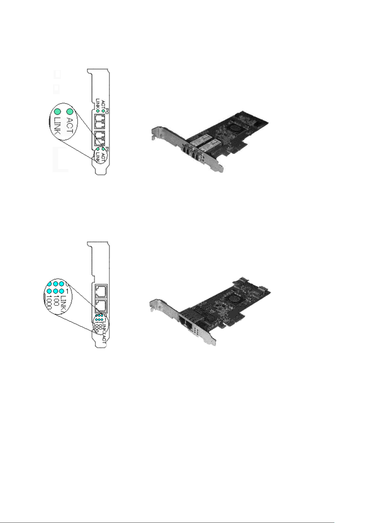
Figure 1.1 1000Base-SX * 2ports (SE0X7GD2X)
Figure 1.2 10/100/1000Base-T * 2ports (SE0X7GD1X)
- 4 -
Page 11
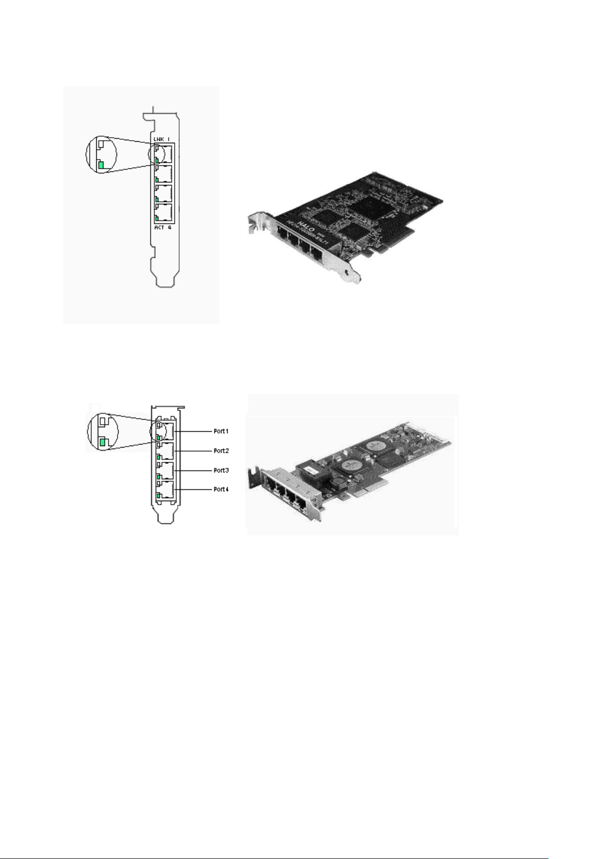
Figure 1.3 10/100/1000Base-T * 4ports (SE0X7GQ1X)
Figure 1.4 10/100/1000Base-T * 4ports (SE0X7GQ2X)
- 5 -
Page 12

Chapter 2 Gigabit Ethernet Card Installation
This chapter describes the tasks necessary to install this card in your system.
Install the hardware with the following procedures.
- 2.1 Installation of the Gigabit Ethernet Card
- 2.2 Identifying the Gigabit Ethernet Card
- 2.3 Cable Connection
2.1 Installation of the Gigabit Ethernet Card
Insert the card into a PCI Express slot on your server.
Please refer to the User's Manual of your server for details about installing cards and specific PCI Express slot specifications.
Information
- Even when the system works, the device can be dynamically installed by the PCI hot plug feature of Solaris (*1) if the server is one
of the SPARC Enterprise M4000/M5000/M8000/M9000. The device can be dynamically composed by executing the cfgadm(1M)
command or hotplug(1M) command(Solaris 10 9/10 or later). For more information, refer to the "Service Manual" of your server,
System Administration Guide:Basic Administration" of the Oracle Documentation and the "man pages section 1M:System
Administration Commands" of the Oracle Documentation.
*1:The PCI hot plug feature of Solaris is feature that can be physically installed, detached or exchange the device while the system
is working.
2.2 Identifying the Gigabit Ethernet Card
The Gigabit Ethernet card can be identified by executing the "boot -r" command at the ok prompt after installing it into the server.
ok boot -r
Information
- Also, even when the system works, the device can be dynamically identified by the PCI hot plug feature of Solaris if the server is one
of the SPARC Enterprise M4000/M5000/M8000/M9000. The device can be dynamically composed by executing the cfgadm(1M)
command or hotplug(1M) command(Solaris 10 9/10 or later). For more information, refer to the "Service Manual" of your server,
System Administration Guide:Basic Administration" of the Oracle Documentation and the "man pages section 1M:System
Administration Commands" of the Oracle Documentation.
2.3 Cable Connection
Figure 2.1 to 2.4 shows how to connect a cable to the Gigabit Ethernet card.
Connect a multimode optical fiber cable to the connector of the SE0X7GD2X Gigabit Ethernet card.
Connect a CAT5e (Enhanced Category 5) twisted pair cable to the connector of the SE0X7GD1X, SE0X7GQ1X and SE0X7GQ2X Gigabit
Ethernet cards.
- 6 -
Page 13
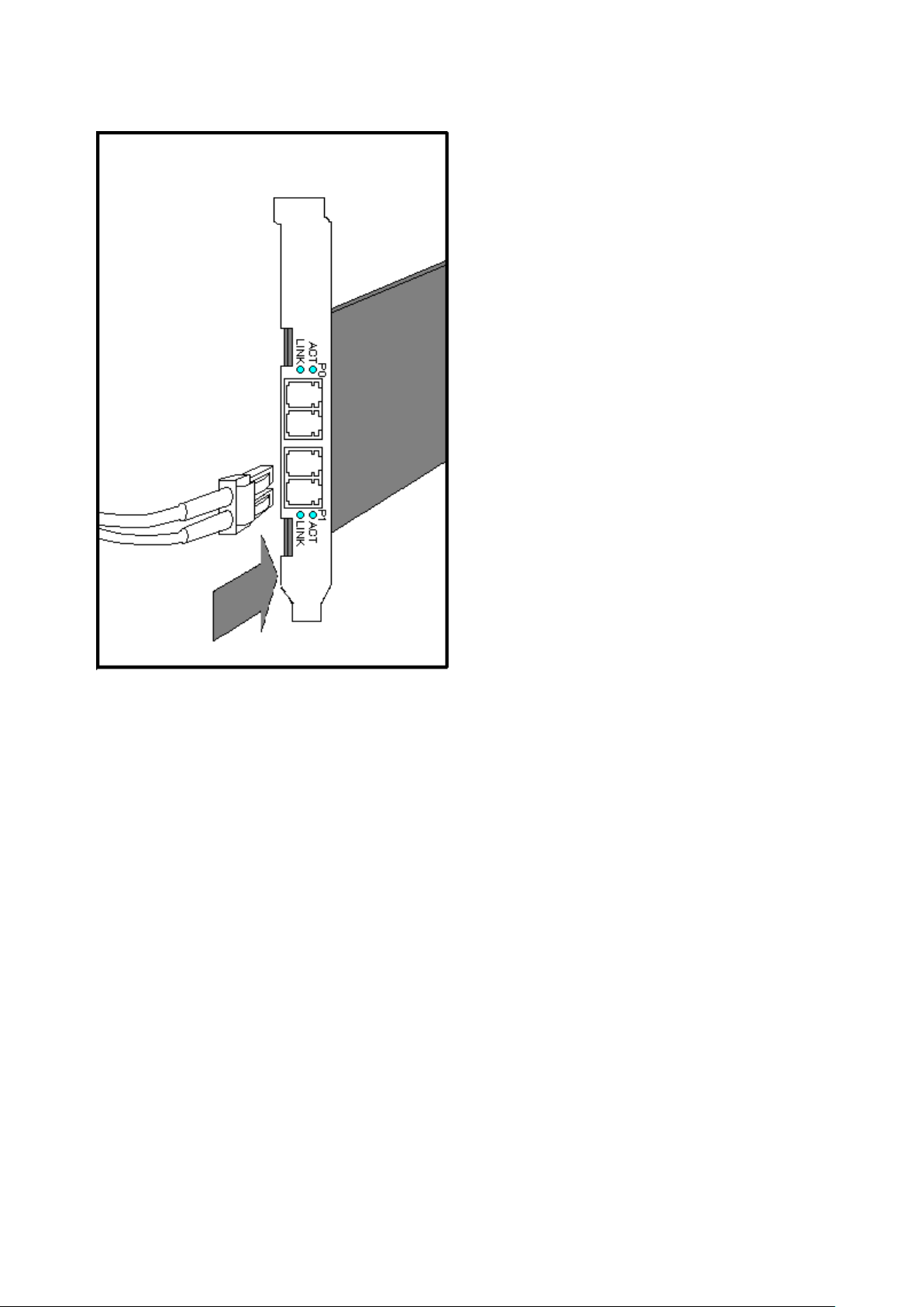
Figure 2.1 SE0X7GD2X (with Multimode Optical Fiber Cable)
- 7 -
Page 14
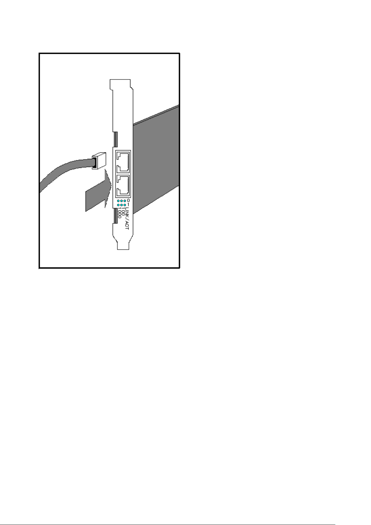
Figure 2.2 SE0X7GD1X (with Twisted Pair CAT5e Cable)
- 8 -
Page 15
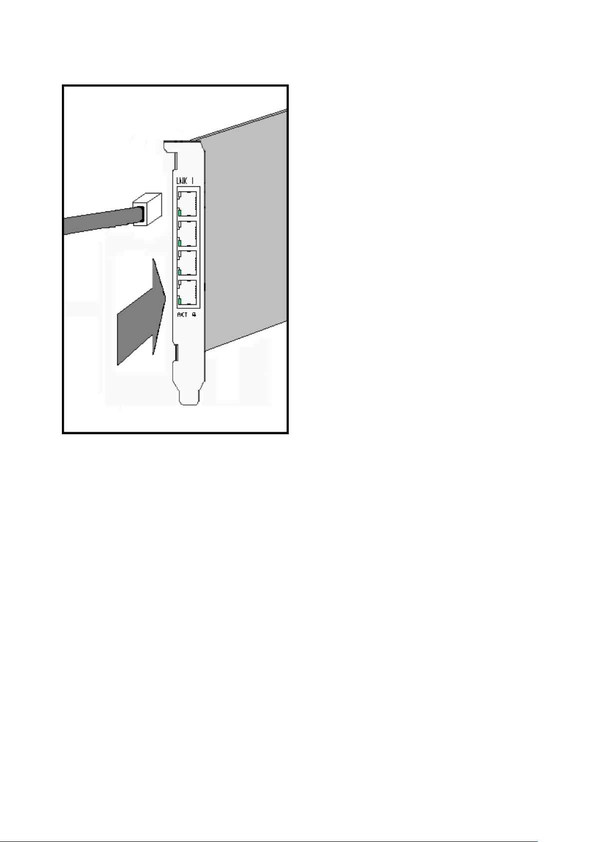
Figure 2.3 SE0X7GQ1X (with Twisted Pair CAT5e Cable)
- 9 -
Page 16
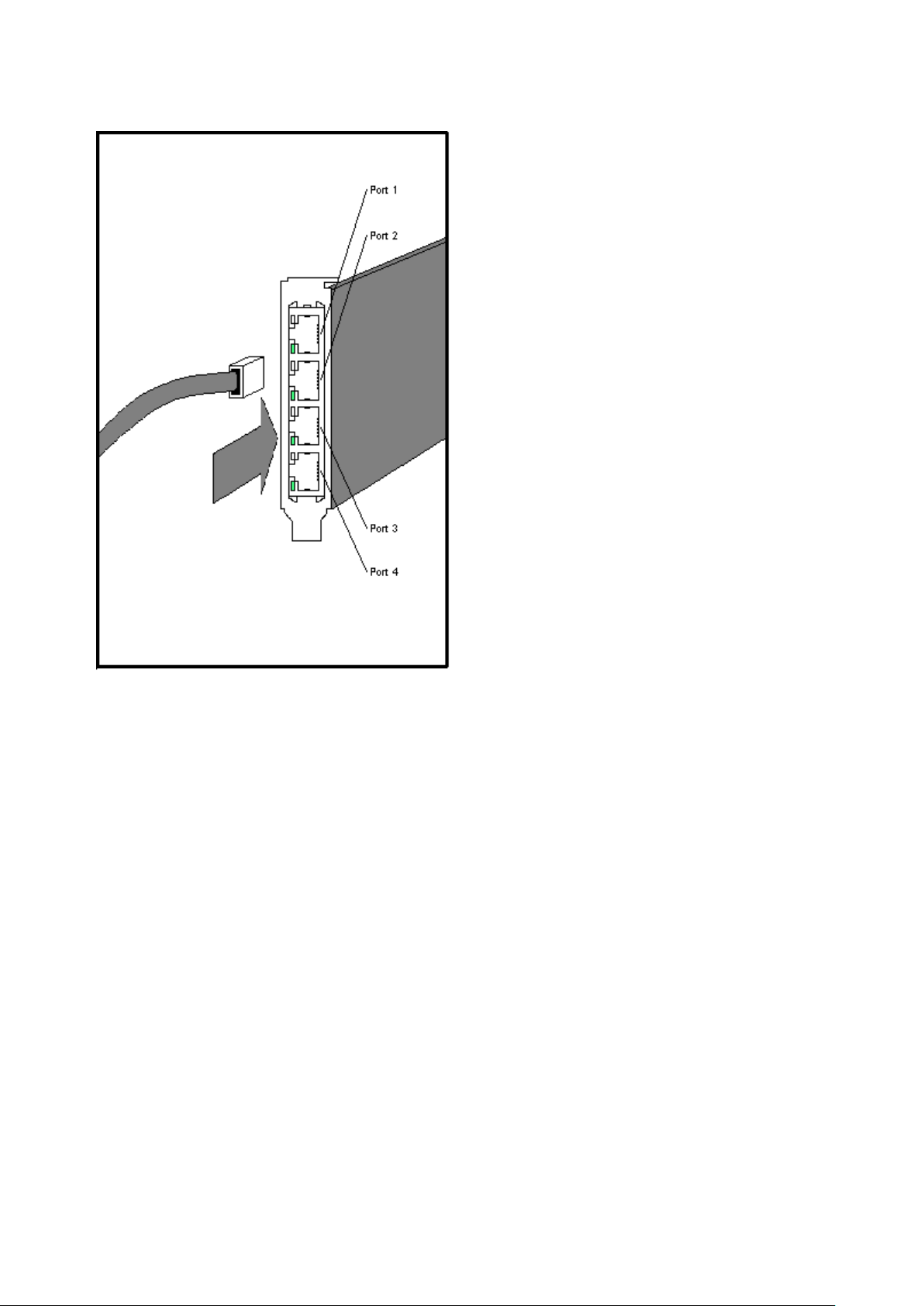
Figure 2.4 SE0X7GQ2X (with Twisted Pair CAT5e Cable)
- 10 -
Page 17

Chapter 3 Setting Instructions
This chapter describes the summary of environment settings required after installing this product.
Install the driver and configure environment settings using the following procedures.
- 3.1 Driver Software Installation
- 3.2 Identification of Interface Name
- 3.2 Identification of Interface Name
- 3.3 Environment Setting
- 3.5 Operation Mode Setup
- 3.6 Network Installation
- 3.7 VLAN Interface Setup
3.1 Driver Software Installation
It is necessary to install the driver software stored on the CD-ROM that ships with the card to use this product. See the document "Installation
Guide FUJITSU PCI GigabitEthernet 4.1 Update2 / 5.0" for installation procedures.
3.2 Identification of Interface Name
In Solaris 11, The interface name is changed into the form of "net*" from the form of "fjgi*" by Vanity Naming.
This section explains how to identify the interface name of fjgi interface.
*1: Please put a decimal number (instance number) in place of the asterisk (*).
See section "3.3 Environment Setting" for detailed information about instance number.
Execute the commands shown in the following examples.
dladm show-phys | grep fjgi
example:
# dladm show-phys | grep fjgi
net2 Ethernet unknown 1000 unknown fjgi0
net3 Ethernet unknown 1000 unknown fjgi1
net4 Ethernet unknown 1000 unknown fjgi2
net5 Ethernet unknown 1000 unknown fjgi3
The installed fjgi interface and the interface name are displayed.
The interface name (Vanity Name, the form of "net*") fjgi interface (the form of "fjgi*")
net2 fjgi0
net3 fjgi1
net4 fjgi2
net5 fjgi3
In the above example, it is displayed that net2 is fjgi0, net3 is fjgi1, and net5 is fjgi3.
In addition, The interface name can be changed by dladm rename-link command. For more information about the dladm(1M) command,
please refer to the "System Administration Guide: IP Services" and the "man pages section 1M: System Administration Commands" of
Oracle Documentation.
- 11 -
Page 18

3.3 Environment Setting
This section explains how to edit the necessary files and use the commands(Solari 11 only) to configure the operating environment for
each FUJITSU PCI GigabitEthernet interface.
For TCP/IP (IPv4 or IPv6), edit the following files and execute the following command(Solaris 11 only).
- Solaris 10 8/07 or later
- /etc/hostname.
fjgi*
(*1) file
- /etc/inet/hosts file or /etc/inet/ipnodes file
- /etc/inet/netmasks file
*1: Please put a decimal number (instance number) in place of the asterisk (*).
See section "3.3 Environment Setting" for detailed information about instance number.
- Solaris 11
- ipadm(1M) command
- /etc/hosts file
*1: For more information about the ipadm(1M) command, please refer to the "System Administration Guide: IP Services" and the
"man pages section 1M: System Administration Commands" of Oracle Documentation.
3.3.1 Environment Setting of IPv4 Interfaces
- Solaris 10 8/07 or later
1. Edit the /etc/hostname.
Assign an IP address or hostname to the fjgi interface by editing the /etc/hostname.fjgi* file (where
name and instance number).
The relationship between IP address and netmask needs to be defined using the procedure described in "3. Edit the /etc/inet/
netmasks file".
fjgi*
file
fjgi*
represents the driver
Example of the /etc/hostname.fjgi* file:
Define a unique hostname (example: giga-v4). (*1)
giga-v4
Or define an IP address (example: 192.168.150.1). (*2)
192.168.150.1
*1: See section "2. Edit the /etc/inet/hosts file" for detailed information about defining the hostname.
*2: Please put neither a blank nor an empty line behind the hostname or IP address. If a blank or an empty line has been
entered, the fjgj driver will not be activated during OS boot.
2. Edit the /etc/inet/hosts file
Define an IP address by a unique name. Describe the relationship between the IP address and hostname in the /etc/inet/hosts
file.
Example of the /etc/inet/hosts file:
Describe the relationship between an IP address (example: 192.168.150.1) and a hostname (example: giga-v4).
# IP Address Hostname
192.168.150.1 giga-v4
- 12 -
Page 19
3. Edit the /etc/inet/netmasks file
Describe the relationship between the network address and the netmask in the /etc/inet/netmasks file.
Example of the /etc/inet/netmasks file:
Describe the relationship between the network address (example: 192.168.150.0) and the netmask (example: 255.255.255.0).
# Network Address netmask
192.168.150.0 255.255.255.0
4. Reboot the system
Reboot the system after editing the above files.
-
Solaris 11
1. How to Use the ipadm(1M) Command
Assign an IP address or hostname and prefix length to the fjgi interface by ipadm(1M) command.
Example:
Setup a unique hostname (example: giga-v4) and prefix length (example: 24) to fjgi interface (example: fjgi0 (this vanity name
is net2)). (*1)
# ipadm create-ip net2
# ipadm create-addr -T static -a giga-v4/24 net2/v4static
Or setup an IP address (example: 192.168.150.1) and prefix length (example: 24) to fjgi interface (example: fjgi0 (this vanity
name is net2)).
# ipadm create-ip net2
# ipadm create-addr -T static -a 192.168.150.1/24 net2/v4static
*1: When you use a hostname, please see section "2. Edit the /etc/hosts file" first.
Information
- The following examples shows how to display an IP address and prefix length that assigned the fjgi interface.
Example:
When setting an IP address (example: 192.168.150.1) and prefix length (example: 24) to fjgi interface (example: fjgi0 (this
vanity name is net2)).
# ipadm show-addr net2/v4static
ADDROBJ TYPE STATE ADDR
net2/v4static static ok 192.168.150.1/24
2. Edit the /etc/hosts file
Define an IP address by a unique name. Describe the relationship between the IP address and hostname in the /etc/hosts file.
Example of the /etc/inet/hosts file:
Describe the relationship between an IP address (example: 192.168.150.1) and a hostname (example: giga-v4).
# IP Address Hostname
192.168.150.1 giga-v4
- 13 -
Page 20

3.3.2 Environment Setting of IPv6 Interfaces
- Solaris 10 8/07 or later
1. Edit the /etc/hostname6.
Assign an IPv6 address or hostname and prefix length to the fjgi interface by editing the /etc/hostname6.fjgi* file (where
represents the driver name and instance number).
Example of the /etc/hostname6.fjgi* file:
Define a unique hostname (example: giga-v6) and prefix length (example: 120). (*1)
addif giga-v6/120 up
Or define an IPv6 address (example: fe80::2e0:ff:fea6:2222) and prefix length (example: 120).
addif fe80::2e0:ff:fea6:2222/120 up
*1: See section "2. Edit the /etc/inet/ipnodes file" when you define a hostname in the /etc/hostname6.fjgi* file.
fjgi*
file
2. Edit the /etc/inet/ipnodes file
Define an IPv6 address by a unique name. Describe the relationship between the IPv6 address and the hostname in the /etc/inet/
ipnodes file.
Example of the /etc/inet/ipnodes file:
Describe the relationship between the IPv6 address (example: fe80::2e0:ff:fea6:2222) and the hostname (example: giga-v6).
# IP Address Hostname
fe80::2e0:ff:fea6:2222 giga-v6
fjgi*
3. Reboot the system
Reboot the system after editing the above files.
- Solaris 11
1. How to Use the ipadm(1M) Command
Assign an IP address or hostname and prefix length to the fjgi interface by ipadm(1M) command.
Example:
Setup a unique hostname (example: giga-v6) and prefix length (example: 120) to fjgi interface (example: fjgi0 (this vanity name
is net2)). (*1)
# ipadm create-ip net2
# ipadm create-addr -T addrconf net2/v6addrconf
# ipadm create-addr -T static -a giga-v6/24 net2/v4static
Or setup an IP address (example: fe80::2e0:ff:fea6:2222) and prefix length (example: 120) to fjgi interface (example: fjgi0 (this
vanity name is net2)).
# ipadm create-ip net2
# ipadm create-addr -T addrconf net2/v6addrconf
# ipadm create-addr -T static -a fe80::2e0:ff:fea6:2222/120 net2/v6static
*1: When you use a hostname, please see section "2. Edit the /etc/hosts file" first.
- 14 -
Page 21

Information
- The following example shows how to display an IP address and prefix length that assigned the fjgi interface.
Example:
When setting an IP address (example: 192.168.150.1) and prefix length (example: 24) to fjgi interface (example: fjgi0 (this
vanity name is net2)).
# ipadm show-addr net2/v4static
ADDROBJ TYPE STATE ADDR
net2/v6static static ok fe80::2e0:ff:fea6:2222/120
2. Edit the /etc/hosts file
Define an IPv6 address by a unique name. Describe the relationship between the IPv6 address and the hostname in the /etc/inet/
ipnodes file.
Example of the /etc/hosts file:
Describe the relationship between the IPv6 address (example: fe80::2e0:ff:fea6:2222) and the hostname (example: giga-v6).
# IP Address Hostname
fe80::2e0:ff:fea6:2222 giga-v6
Information
- In Solaris 10 8/07 or later, to delete the environment settings, please delete each of the settings made in the procedures described in
"3.3.1 Environment Setting of IPv4 Interfaces" and "3.3.2 Environment Setting of IPv6 Interfaces" from the files.
- In Solaris 11, to delete the environment settings, please execute the following ipadm(1M) commnad and delete each of the settings
made in the procedures described in "3.3.1 Environment Setting of IPv4 Interfaces" and "3.3.2 Environment Setting of IPv6
Interfaces" from the files.
Example:
# ipadm delete-ip net2
- To use VLAN interfaces, please refer first to "3.7.2 Setting Up the VLAN Interface" to define the interface name. Then, please carry
out the procedures described in "3.3.1 Environment Setting of IPv4 Interfaces" or "3.3.2 Environment Setting of IPv6 Interfaces".
3.4 Identification of the Gigabit Ethernet Card
This section explains how to identify a slot in which the Gigabit Ethernet card has been installed, on SPARC Enterprise.
Execute the commands shown in the following examples.
- Identification of the Gigabit Ethernet Card Types and Instance Number
prtconf -D | grep fjgi
example:
# prtconf -D | grep fjgi
FJSV,e4ta, instance #0 (driver name: fjgi)
FJSV,e4ta, instance #1 (driver name: fjgi)
FJSV,e4ta, instance #2 (driver name: fjgi)
FJSV,e4ta, instance #3 (driver name: fjgi)
FJSV,e2sa, instance #4 (driver name: fjgi)
FJSV,e2sa, instance #5 (driver name: fjgi)
- 15 -
Page 22

FJSV,e2ta, instance #6 (driver name: fjgi)
FJSV,e2ta, instance #7 (driver name: fjgi)
FJSV,e4tb, instance #8 (driver name: fjgi)
FJSV,e4tb, instance #9 (driver name: fjgi)
FJSV,e4tb, instance #10 (driver name: fjgi)
FJSV,e4tb, instance #11 (driver name: fjgi)
The installed Gigabit Ethernet card types and instance numbers (shown in bold, above) are displayed.
Gigabit Ethernet card types:
FJSV,e4ta SE0X7GQ1X (10/100/1000Base-T * 4ports) card
FJSV,e2sa SE0X7GD2X (1000BASE-SX * 2ports) card
FJSV,e2ta SE0X7GD1X (10/100/1000BASE-T * 2ports) card
FJSV,e4tb SE0X7GQ2X (10/100/1000BASE-T * 4ports) card
In this example, the following types of installed Gigabit Ethernet cards can be identified: e4ta (SE0X7GQ1X), e2sa (SE0X7GD2X), e2ta
(SE0X7GD1X) and e4tb (SE0X7GQ2X).
Instance numbers:
In this example, the following instance numbers of installed Gigabit Ethernet cards can be identified:
e4ta: 0, 1, 2, 3
e2sa: 4, 5
e2ta: 6, 7
e4tb: 8, 9, 10, 11
- Identification of Slots with Installed Gigabit Ethernet Cards
more /etc/path_to_inst | grep fjgi
example:
# more /etc/path_to_inst | grep fjgi
"/pci@1,700000/pci@0/FJSV,e4ta@4" 0 "fjgi"
"/pci@1,700000/pci@0/FJSV,e4ta@4,1" 1 "fjgi"
"/pci@1,700000/pci@0,1/FJSV,e4ta@6" 2 "fjgi"
"/pci@1,700000/pci@0,1/FJSV,e4ta@6,1" 3 "fjgi"
"/pci@2,600000/pci@0/FJSV,e2sa@4" 4 "fjgi"
"/pci@2,600000/pci@0/FJSV,e2sa@4,1" 5 "fjgi"
"/pci@3,700000/pci@0/FJSV,e2ta@4" 6 "fjgi"
"/pci@3,700000/pci@0/FJSV,e2ta@4,1" 7 "fjgi"
"/pci@4,600000/pci@0/FJSV,e4tb@4" 8 "fjgi"
"/pci@4,600000/pci@0/FJSV,e4tb@4,1" 9 "fjgi"
"/pci@4,600000/pci@0,1/FJSV,e4tb@6" 10 "fjgi"
"/pci@4,600000/pci@0,1/FJSV,e4tb@6,1" 11 "fjgi"
The installed logical bus addresses and the instance numbers (shown in bold, above) are displayed.
Identification of the logical bus addresses, instance numbers and driver name for each interface:
Logical bus address Instance number Driver name
"/pci@1,700000/pci@0/FJSV,e4ta@4" 0 fjgi
"/pci@1,700000/pci@0/FJSV,e4ta@4,1" 1 fjgi
"/pci@1,700000/pci@0,1/FJSV,e4ta@6" 2 fjgi
- 16 -
Page 23

Logical bus address Instance number Driver name
"/pci@1,700000/pci@0,1/FJSV,e4ta@6,1" 3 fjgi
"/pci@3,700000/pci@0/FJSV,e2sa@4" 4 fjgi
"/pci@3,700000/pci@0/FJSV,e2sa@4,1" 5 fjgi
"/pci@2,600000/pci@0/FJSV,e2ta@4" 6 fjgi
"/pci@2,600000/pci@0/FJSV,e2ta@4,1" 7 fjgi
"/pci@4,600000/pci@0/FJSV,e4tb@4" 8 fjgi
"/pci@4,600000/pci@0/FJSV,e4tb@4,1" 9 fjgi
"/pci@4,600000/pci@0,1/FJSV,e4tb@6" 10 fjgi
"/pci@4,600000/pci@0,1/FJSV,e4tb@6,1" 11 fjgi
The relationship of logical bus addresses to physical slot numbers differs in each server. To determine the relationship, please refer to
"Appendix G PCI Slot Number and Device Name".
3.5 Operation Mode Setup
This section explains how to edit the fjgi.conf configuration file or use the command line to change the operation mode of FUJITSU PCI
GigabitEthernet interfaces. Setup of the following operation modes are described below.
- 3.5.1 Setting the fjgi.conf File
- 3.5.2 JumboFrame Setup
- 3.5.3 Using the ndd(1M) command
- 3.5.4 Using the dladm(1M) command
- 3.5.5 FCode Settings
3.5.1 Setting the fjgi.conf File
Usually, setup of the fjgi.conf file is unnecessary. Default settings are appropriate in most environments.
The following examples show cases when the fjgi.conf file needs to be modified.
Example:
- When the remote device does not support Auto-Negotiation.
In this case, please set the same mode of operation for the local and remote devices.
- When Auto-Negotiation is used, but it is desirable to use a specific setting value, different from the default value (for example, when
you want to set the speed to 100Mbps in order to keep the CPU load by the network low).
- When JumboFrame is used.
For details, please refer to "3.5.2 JumboFrame Setup".
Using Auto-Negotiation (the default settings) is recommended for speed, duplex, and flow control.
To change the operation mode, there are two methods; "Method 1: Setting method of new style" and "Method 2: Setting method of old
style". When there is a mistake in parent and unit-address setting by the "Method 2", warning messages may be displayed repeatedly.
Therefore the "Method 1: Setting method of new style" is recommended.
When editing the fjgi.conf file, please review the [Cautions] in the following sections.
- Method 1: Setting method of new style (Recommended)
[Parameter List]
- 17 -
Page 24

Parameter Value Description
LinkSpeed_A (*1)
DuplexCapabilities_A (*1)
Any connection speed of 1000, 100, or 10
Auto (default)
1000
100 Connect at 100Mbps.
10 Connect at 10Mbps.
Both (default)
Half
Full Full-Duplex operation is enabled.
Mbps is set based on negotiation with the
remote device. (This is effective only
when AutoNegotiation_A=On.)
Connect at 1000Mbps.
Both Full-Duplex and Half-Duplex are
enabled. (This is effective only when
AutoNegotiation_A=On.)
Half-Duplex operation is enabled.
Auto (default)
Rem
FlowControl_A (*2)
LocSend
None
fjgi_mtu 1500 (default) to 9000 (*3) MTU (byte) is specified.
On (default)
AutoNegotiation_A
Off
Auto (default)
Role_A (*4)
Flow control is performed according to
the setup of the remote device.
Only flow control from the remote device
is allowed. Flow control from the local
device is not allowed.
Only flow control from the local device is
allowed. Flow control from the remote
device is not allowed.
Flow control is disabled.
Auto-Negotiation is enabled. The
interface will not be able to communicate
with remote device operating in fixed
mode (Auto-Negotiation disabled).
When SE0X7GD1X, SE0X7GQ1X,
SE0X7GQ2X is used in 1000Mbps mode,
use this setting.
Auto-Negotiation is disabled. (Forced
mode)
Master or Slave is set based on
negotiation with the remote device. (This
is effective only when
AutoNegotiation_A= On.)
ReceiveTicks
TransmitTicks
ReceiveMaxBD
Master
Slave Communication by Slave.
0 to 1000 (*3)
(default: 77)
0 to 1000 (*3)
(default: 500)
1 to 500 (*3)
(default: 10)
- 18 -
Communication by Master.
Time to wait for an interrupt for receiving
is specified (micro seconds). (*5)
Time to wait for an interrupt for
transmitting is specified (micro seconds).
(*5)
The number of buffer descriptor to wait
for an interrupt for receiving is specified.
(*5)
Page 25

Parameter Value Description
TransmitMaxBD
fjgi* (*6)
*1: Parameter is supported on 10/100/1000Base-T (SE0X7GD1X, SE0X7GQ1X, SE0X7GQ2X) adapters only.
*2: Parameter is effective only when AutoNegotiation_A=On. When AutoNegotiation_A=Off, it becomes FlowControl_A=None.
*3: Specify the value as a decimal figure.
*4: Parameter is supported on 10/100/1000Base-T (SE0X7GD1X, SE0X7GQ1X, SE0X7GQ2X) adapters in 1000Mbps mode only.
*5: These ReceiveTicks, TransmitTicks, ReceiveMaxBD or TransmitMaxBD parameters are tuning parameters about the performance.
*6: Please put a decimal number (instance number) in place of the asterisk (
The fjgi* parameter is used prior to parameters to all instances if the fjgi parameter is specified with LinkSpeed_A,
DuplexCapabilities_A, FlowControl_A, fjgi_mtu, AutoNegotiation_A, Role_A, ReceiveTicks, TransmitTicks, ReceiveMaxBD or
TransmitMaxBD parameters.
1 to 500 (*3)
(default: 128)
<LinkSpeed_A>
:<DuplexCapabilities_A>
:<FlowControl_A>
:<fjgi_mtu>
:<AutoNegotiation_A>
:<Role_A>
:<ReceiveTicks>
:<TransmitTicks>
:<ReceiveMaxBD>
:<TransmitMaxBD> (*7)
*
).
The number of buffer descriptor to wait
for an interrupt for transmitting is
specified. (*5)
Parameter setting values are specified for
every instance.
Refer to the description of each parameter
for the meaning of each value.
*7: The default values are used when setting values are omitted.
[Parameter Setting]
The following examples show how to set the fjgi.conf file.
- The location of the fjgi.conf file depends on the model of the host system as described below:
1. SPARC Enterprise Txxxx series and SPARC T3 series
/platform/sun4v/kernel/drv/fjgi.conf
2. SPARC Enterprise Mxxxx series
/platform/SUNW,SPARC-Enterprise/kernel/drv/fjgi.conf
- How to set a parameter to all instances
Example 1: The parameters for all instances are set to "Auto-Negotiation is disabled", "Connect at 100Mbps" and "Half-Duplex
operation is enabled".
The parameter values need to be set by character strings like AutoNegotiation_A="Off", LinkSpeed_A="100" and
DuplexCapabilities_A="Half".
The following is added to the fjgi.conf file:
AutoNegotiation_A="Off"
LinkSpeed_A="100"
DuplexCapabilities_A="Half";
Example 2: The parameters for all instances are set to "Auto-Negotiation is enabled", "Connect at 100Mbps" and "Full-Duplex
operation is enabled".
- 19 -
Page 26

The parameter values need to be set by character strings like AutoNegotiation_A="On", LinkSpeed_A="100" and
DuplexCapabilities_A="Full".
The following is added to the fjgi.conf file:
AutoNegotiation_A="On"
LinkSpeed_A="100"
DuplexCapabilities_A="Full";
Example 3: The MTU parameter for all instances is set to 8000.
The parameter value needs to be set by numerical value like fjgi_mtu=8000.
The following is added to the fjgi.conf file:
fjgi_mtu=8000;
Note: After making changes to the fjgi.conf file, the system must be rebooted. The settings become effective after rebooting.
- How to set a parameter to each instance
Example 1: The parameters for fjgi0 is set to "Auto-Negotiation is disabled", "Connect at 100Mbps" and "Half-Duplex operation is
enabled".
The parameter value needs to be set by a character string like fjgi0="100:Half:::Off:::::".
The following is added to the fjgi.conf file:
fjgi0="100:Half:::Off:::::";
Example 2: The parameters for fjgi1 is set to "Auto-Negotiation is disabled", "Connect at 100Mbps" and "Half-Duplex operation is
enabled".
The parameter value needs to be set by a character string like fjgi1="100:Half:Auto:1500:Off:Auto::::".
The following is added to the fjgi.conf file:
fjgi1="100:Half:Auto:1500:Off:Auto::::";
Example 3: The parameters for fjgi0 is set to "Auto-Negotiation is enabled", "Connect at 100Mbps" and "Full-Duplex operation is
enabled".
The parameter value needs to be set by a character string like fjgi0="100:Full:::On:::::".
The following is added to the fjgi.conf file:
fjgi0="100:Full:::On:::::";
Example 4: The parameters for fjgi1 is set to "Auto-Negotiation is enabled", "Connect at 100Mbps" and "Full-Duplex operation is
enabled".
The parameter value needs to be set by a character string like fjgi1="100:Full:Auto:1500:On:Auto::::".
The following is added to the fjgi.conf file:
fjgi1="100:Full:Auto:1500:On:Auto::::";
Example 5: The MTU parameter for fjgi0 is set to 8000.
- 20 -
Page 27

The parameter value needs to be set by a character string like fjgi0=":::8000::::::".
The following is added to the fjgi.conf file:
fjgi0=":::8000::::::";
Example 6: The MTU parameter for fjgi1 is set to 8000.
The parameter value needs to be set by a character string like fjgi1="Auto:Both:Auto:8000:On:Auto::::".
The following is added to the fjgi.conf file:
fjgi1="Auto:Both:Auto:8000:On:Auto::::";
Note: After making changes to the fjgi.conf file, the system must be rebooted. The settings become effective after rebooting.
- How to set parameters to all instances and to each instance
Example 1: The MTU parameter for all instances is set to 1500 and the MTU parameter for fjgi0 is set to 8000.
In this case, the MTU of fjgi0 is 8000, and the MTU of other instances is 1500.
The following is added to the fjgi.conf file:
fjgi_mtu=1500;
fjgi0=":::8000::::::";
Note: After making changes to the fjgi.conf file, the system must be rebooted. The settings become effective after rebooting.
- Method 2: Setting method of old style
[Parameter List]
Parameter Value Description
name fjgi Used to specify the driver name.
parent See below
unit-address See below
Auto (default)
LinkSpeed_A (*1)
1000
100 Connect at 100Mbps.
10 Connect at 10Mbps.
Both (default)
DuplexCapabilities_A (*1)
Half
Used to specify the location of the device
node in the device tree.
Used to specify the address within the
device node.
Any connection speed of 1000, 100, or 10
Mbps is set based on negotiation with the
remote device. (This is effective only
when AutoNegotiation_A=On.)
Connect at 1000Mbps.
Both Full-Duplex and Half-Duplex are
enabled. (This is effective only when
AutoNegotiation_A=On.)
Half-Duplex operation is enabled.
FlowControl_A (*2)
Full Full-Duplex operation is enabled.
Auto (default)
- 21 -
Flow control is performed according to
the setup of the remote device.
Page 28

Parameter Value Description
Only flow control from the remote device
Rem
LocSend
is allowed. Flow control from the local
device is not allowed.
Only flow control from the local device is
allowed. Flow control from the remote
device is not allowed.
None
fjgi_mtu 1500 (default) to 9000 (*3) MTU (byte) is specified.
On (default)
AutoNegotiation_A
Off
Auto (default)
Role_A (*4)
Master
Slave Communication by Slave.
ReceiveTicks 0 to 1000 (*3)
(default: 77)
TransmitTicks 0 to 1000 (*3)
(default: 500)
Flow control is disabled.
Auto-Negotiation is enabled. The
interface will not be able to communicate
with remote device operating in fixed
mode (Auto-Negotiation disabled).
When SE0X7GD1X, SE0X7GQ1X,
SE0X7GQ2X is used in 1000Mbps mode,
use this setting.
Auto-Negotiation is disabled. (Forced
mode)
Master or Slave is set based on
negotiation with the remote device. (This
is effective only when
AutoNegotiation_A= On.)
Communication by Master.
Time to wait for an interrupt for receiving
is specified (micro seconds). (*5)
Time to wait for an interrupt for
transmitting is specified (micro seconds).
(*5)
ReceiveMaxBD 1 to 500 (*3)
(default: 10)
TransmitMaxBD 1 to 500 (*3)
(default: 128)
*1: Parameter is supported on 10/100/1000Base-T (SE0X7GD1X, SE0X7GQ1X, SE0X7GQ2X) adapters only.
*2: Parameter is effective only when AutoNegotiation_A=On. When AutoNegotiation_A=Off, it becomes FlowControl_A=None.
*3: Specify the value as a decimal figure.
*4: Parameter is supported on 10/100/1000Base-T (SE0X7GD1X, SE0X7GQ1X, SE0X7GQ2X) adapters in 1000Mbps mode only.
*5: These ReceiveTicks, TransmitTicks, ReceiveMaxBD or TransmitMaxBD parameters are tuning parameters about the performance.
The number of buffer descriptor to wait
for an interrupt for receiving is specified.
(*5)
The number of buffer descriptor to wait
for an interrupt for transmitting is
specified. (*5)
[Parameter Setting]
The following shows how to set the parent and unit-address parameters in the fjgi.conf file.
- Find the fjgi device tree, device node and instance number in the /etc/path_to_inst file.
Example:
- 22 -
Page 29

- From the above example, instance number and driver name for each interface can be determined.
Device node of device tree Instance number Driver name
/pci@1,700000/pci@0/FJSV,e4ta@4 0 fjgi
/pci@1,700000/pci@0/FJSV,e4ta@4,1 1 fjgi
/pci@1,700000/pci@0,1/FJSV,e4ta@6 2 fjgi
/pci@1,700000/pci@0,1/FJSV,e4ta@6,1 3 fjgi
/pci@2,600000/pci@0/FJSV,e2sa@4 4 fjgi
/pci@2,600000/pci@0/FJSV,e2sa@4,1 5 fjgi
/pci@3,700000/pci@0/FJSV,e2ta@4 6 fjgi
/pci@3,700000/pci@0/FJSV,e2ta@4,1 7 fjgi
/pci@4,600000/pci@0/FJSV,e4tb@4 8 fjgi
/pci@4,600000/pci@0/FJSV,e4tb@4,1 9 fjgi
/pci@4,600000/pci@0,1/FJSV,e4tb@6 10 fjgi
/pci@4,600000/pci@0,1/FJSV,e4tb@6,1 11 fjgi
- The parent and unit-addresses from the example are shown below. The parent is the character string to the left of FJSV,e4ta@,
FJSV,e2sa@, FJSV,e2ta@, or FJSV,e4tb@. The unit-address is the number to the right of FJSV,e4ta@, FJSV,e2sa@, FJSV,e2ta@,
or FJSV,e4tb@.
SE0X7GQ1X
name fjgi
parent /pci@1,700000/pci@0 /pci@1,700000/pci@0,1
unit-address
instance 0 is 4
instance 1 is 4,1
instance 2 is 6
instance 3 is 6,1
SE0X7GD2X
name fjgi
parent /pci@2,600000/pci@0
unit-address
instance 4 is 4
instance 5 is 4,1
- 23 -
Page 30

name fjgi
parent /pci@3,700000/pci@0
SE0X7GD1X
unit-address
instance 6 is 4
instance 7 is 4,1
SE0X7GQ2X
name fjgi
parent /pci@4,600000/pci@0 /pci@4,600000/pci@0,1
unit-address
instance 8 is 4
instance 9 is 4,1
instance 10 is 6
instance 11 is 6,1
- The location of the fjgi.conf file depends on the model of the host system as described below:
1. SPARC Enterprise Txxxx series and SPARC T3 series
/platform/sun4v/kernel/drv/fjgi.conf
2. SPARC Enterprise Mxxxx series
/platform/SUNW,SPARC-Enterprise/kernel/drv/fjgi.conf
- Examples of setting parameters in the fjgi.conf file are shown below.
Example 1: The parameters for fjgi0 (the instance number 0 port of SE0X7GQ1X (10/100/1000BASE-T)) is set to "Auto-Negotiation
is disabled", "Connect at 100Mbps" and "Half-Duplex operation is enabled".
The parameter values need to be set by a character string like name="fjgi", parent="/pci@1,700000/pci@0", unit-address="4",
AutoNegotiation_A="Off", LinkSpeed_A="100", DuplexCapabilities_A="Half".
The following is added to the fjgi.conf file:
name="fjgi" parent="/pci@1,700000/pci@0" unit-address="4"
AutoNegotiation_A="Off" LinkSpeed_A="100" DuplexCapabilities_A="Half";
Example 2: The parameters for fjgi4 (the instance number 4 port of SE0X7GD2X (1000BASE-SX)) is set to "Auto-Negotiation is
enabled", "Connect at 100Mbps" and "Full-Duplex operation is enabled".
The parameter values need to be set by a character string like name="fjgi", parent="/pci@2,600000/pci@0", unit-address="4",
AutoNegotiation_A="On", LinkSpeed_A="100", DuplexCapabilities_A="Full".
The following is added to the fjgi.conf file:
name="fjgi" parent="/pci@2,600000/pci@0" unit-address="4"
AutoNegotiation_A="On" LinkSpeed_A="100" DuplexCapabilities_A="Full";
Example 3: The MTU parameter for fjgi9 (the instance number 9 port of SE0X7GQ2X (10/100/1000BASE-T)) is set to 8000.
The parameter value needs to be set by numerical value like fjgi_mtu=8000.
The following is added to the fjgi.conf file:
name="fjgi" parent="/pci@4,600000/pci@0" unit-address="4,1"
fjgi_mtu=8000;
- 24 -
Page 31

Example 4: The parameters for all instances are set to "Auto-Negotiation is disabled", "Connect at 100Mbps" and "Half-Duplex
operation is enabled".
The parameter value needs to be set by a character string like AutoNegotiation_A="Off", LinkSpeed_A="100",
DuplexCapabilities_A="Half".
The following is added to the fjgi.conf file:
AutoNegotiation_A="Off";
LinkSpeed_A="100";
DuplexCapabilities_A="Half";
Example 5: The parameters for all instances are set to "Auto-Negotiation is enabled", "Connect at 100Mbps" and "Full-Duplex
operation is enabled".
The parameter value needs to be set by a character string like AutoNegotiation_A="On", LinkSpeed_A="100",
DuplexCapabilities_A="Full".
The following is added to the fjgi.conf file:
AutoNegotiation_A="On";
LinkSpeed_A="100";
DuplexCapabilities_A="Full";
Example 6: The MTU parameter for all instances is set to 8000.
The parameter value needs to be set by numerical value like fjgi_mtu=8000.
The following is added to the fjgi.conf file:
fjgi_mtu=8000;
Example 7: The MTU parameter for all instances is set to 1500 and the MTU parameter for fjgi0 (the instance number 0 port of
SE0X7GQ1X (10/100/1000BASE-T)) is set to 8000.
In this case, the MTU of fjgi0 is 8000, and the MTU of other instances is 1500.
The following is added to the fjgi.conf file:
fjgi_mtu=1500;
name="fjgi" parent="/pci@1,700000/pci@0" unit-address="4" fjgi_mtu=8000;
Note: After making changes to the fjgi.conf file, the system must be rebooted. The settings become effective after rebooting.
Note
- Using Auto-Negotiation (the default setting) is recommended for speed, duplex, and flow control. When Auto-Negotiation is used,
the remote device should also be setup for Auto-Negotiation. Using Auto-Negotiation on both local and remotes devices allows the
appropriate speed, duplex, and flow control to be set up automatically.
- When you use the fjgi.conf file to change the mode of operation, please set the same mode of operation on local and remote devices.
When the mode of operation is not the same between local and remote devices, link up may fail, a communication error may occur
(even if link is up), or the mode of operation may not be the same as specified.
- The default values of the tuning parameter which provide higher throughput are recommended for the most systems. Only when you
need a smaller latency for a specific use, change the values of the parameters. You need to check if the specified parameters provide
a suitable latency and throughput for your systems. When the values of these parameters are set small, the latency will be improved,
but the throughput will fall.
- 25 -
Page 32

- When "Method 1: Setting method of new style" and "Method 2: Setting method of old style" are specified at the same time, the driver
gives priority to the "Method 1: Setting method of new style". And when "How to set a parameter to all instances" and "How to set a
parameter to each instance" are specified at the same time, the driver gives priority to the "How to set a parameter to each instance".
- When a Gigabit Ethernet card is removed, please remove the setting parameters of the applicable adapter defined in the fjgi.conf file.
If an adapter is removed and the setting parameters are left in the fjgi.conf file, a panic may occur at system boot, causing boot failure.
- Because the parameters are set in the fjgi.conf file per physical interface, when a VLAN interface is used, individual interfaces used
by the VLAN interface must be similarly configured.
- The operation mode setup in the fjgi.conf file after system boot may not become effective after installation with DR (Dynamic
Reconfiguration) or PCI Hot Plug functions. Check the operation mode with the ndd(1M) command or dladm(1M) command (Solaris
11 only). If the operation mode is not correct, reboot the system and the desired operation mode will become effective.
3.5.2 JumboFrame Setup
By using a JumboFrame the TCP/IP MTU can be expanded from 1500 to 9000. By expanding the single packet transmission size, the
number of packets processed can be reduced, and lowering the CPU load is possible.
JumboFrame can be enabled using either of the following three procedures.
- Method 1: Specify in /etc/system and /etc/hostname.fjgi*
When MTU settings must be individually set for each interface, or when the application uses /etc/hostname.fjgi*, please use this method.
1. Add the following line to the /etc/system file.
set fjgi:fjgi_jumbo=1
2. The MTU of TCP/IP is set by defining an MTU size between 1500 and 9000 in /etc/hostname.fjgi* (*1) in the following format
and then rebooting the system. When no MTU value is specified in this file, the default value is set (9000bytes).
*1: The asterisk (*) expresses an instance number. When IPv6 interface is used, assign an IP address or hostname and an MTU
size to the fjgi interface by editing the /etc/hostname6.fjgi* file.
Setting format
hostname mtu MTU
Example of setting (when setting MTU of fjgi0 to 8000):
# cat/etc/hostname.fjgi0
myhost mtu 8000
3. Reboot the system.
- Method 2: Specify in fjgi.conf File
When MTU settings must be individually set for each interface, or when the application does not use /etc/hostname.fjgi* (example:
PRIMECLUSTER CF (Cluster Foundation) or CIP (Cluster Interconnect Protocol) function), please use this method.
Refer to the "3.5.1 Setting the fjgi.conf File" for the setting procedures of JumboFrame.
- Setting method of new style (Recommended)
1. Add the fjgi* parameter to the fjgi.conf file. The parameter value needs to be set by a character string like fjgi0=":::8000::::::".
Example of file description (The MTU parameter for fjgi0 is set to 8000):
- 26 -
Page 33

fjgi0=":::8000::::::";
2. Reboot the system.
- Setting method of old style
1. Add the fjgi_mtu parameter to the fjgi.conf file. The parameter value needs to be set by numerical value like fjgi_mtu=8000.
Example of file description (The MTU parameter for fjgi0 is set to 8000):
name="fjgi" parent="/pci@1,700000/pci@0" unit-address="4"
fjgi_mtu=8000;
2. Reboot the system.
- Method 3: Specify in dladm(1M) command
This method can be used only by FUJITSU PCI GigabitEthernet 5.0 or later. When MTU settings must be individually set for each interface
without reboot, please use this method.
Refer to the "3.5.1 Setting the fjgi.conf File" for the setting procedures of JumboFrame.
- Setup MTU by the following command.
dladm set-linkprop -p mtu=value link
Example(when setting MTU of fjgi0 (this vanity name is net2) to 8000):
# dladm set-linkprop -p mtu=8000 net2
- Settings are displayed by the following command.
dladm show-linkprop -p mtu link
Example(when setting MTU of fjgi0 (this vanity name is net2) to 8000):
# dladm show-linkprop -p mtu net2
LINK PROPERTY PERM VALUE DEFAULT POSSIBLE
net2 mtu rw 8000 1500 1500-9000
Note
- If JumboFrame feature is enabled, the interface will be unable to transmit and receive data in IEEE802.3 format.
- When JumboFrame has been enabled with Method 1, if two or more interfaces or VLAN interfaces are installed, the JumboFrame
setting applies to all interfaces.
- It is necessary to inactivate a corresponding interface with the ifconfig(1M) command before JumboFrame has been enabled with
Method 3. Then activate a corresponding interface with the ifconfig(1M) command after enabled.
- When using the JumboFrames feature with the SE0X7GD1X, SE0X7GQ1X or SE0X7GQ2X, use 1000Mbps mode.
- The JumboFrame function setup in /etc/hostname.fjgi* or fjgi.conf files after system started may not become effective after hot plug
or installation with the DR (Dynamic Reconfiguration) and PCI Hot Plug functions. Check the JumboFrame function with the ndd(1M)
command or dladm(1M) command (Solaris 11 only). If the JumboFrame function is not correct, reboot the system and the JumboFrame
function will become effective.
- When the interface is connected to a LAN switch, it is necessary to enable the JumboFrame feature on the LAN switch. For more
information on the JumboFrame feature of the LAN switch, please refer to the specifications of each LAN switch.
- 27 -
Page 34

3.5.3 Using the ndd(1M) command
By using the ndd(1M) command, the interface communication mode can be changed dynamically. Usually it is not necessary to change
the interface communication mode using the ndd(1M) command, but when you experience the following, please change the interface
communication mode using the ndd(1M) command.
This method is not supported by FUJITSU PCI GigabitEthernet 5.0 or later.
Example
- You changed a remote device from one which supports Auto-Negotiation to another which does not support Auto-Negotiation or vice
versa after system startup.
Note
- When using the ndd(1M) command to change interface communication modes, it is necessary to change or reset the Link Status
making the changes. This causes the changes to be recognized by the hardware and dynamically take effect. Using ndd(1M) to change
the adv_autoneg_cap parameter cause a Link Status change. Please note in the "To set" examples below that the last step is always a
change to the adv_autoneg_cap parameter.
- How to Use the ndd(1M) Command
The following examples show how to display and set parameters using the ndd(1M) command.
- To display:
ndd -get /dev/fjgi* param
(Note) Please put a decimal number (instance number) in place of the asterisk (*).
example: The state of the link of fjgi2 will be displayed.
# ndd -get /dev/fjgi2 link_status
1
- To set:
ndd -set /dev/fjgi* param value
(Note) Please put a decimal number (instance number) in place of the asterisk (*).
after
example: 1000Mbps/FullDuplex is disabled on interface fjgi2.
# ndd -set /dev/fjgi2 adv_1000fdx_cap 0
(Note) In this stage, the setting is not reflected in hardware yet.
- When the setting change is reflected in hardware (with no change of an Auto-Negotiation value):
ndd -set /dev/fjgi* param1 value (Change of setting 1)
ndd -set /dev/fjgi* param2 value (Change of setting 2)
: :
ndd -set /dev/fjgi* adv_autoneg_cap N (Once let Auto-Negotiation have a different value from
the current value.)
ndd -set /dev/fjgi* adv_autoneg_cap M (Auto-Negotiation is returned to the original value.)
(Note) Please put a decimal number (instance number) in place of the asterisk (*).
example: When changing fjgi0 into 100Full (autonego=1, link_sppd=100, link_mode=1) from a default state (autonego=1,
link_speed=1000, link_mode=1) while Auto-Negotiation is enabled.
- 28 -
Page 35

# ndd -set /dev/fjgi0 adv_1000fdx_cap 0
# ndd -set /dev/fjgi0 adv_1000hdx_cap 0
# ndd -set /dev/fjgi0 adv_autoneg_cap 0
# ndd -set /dev/fjgi0 adv_autoneg_cap 1
(Note) The last two commands above change the Auto-Negotiation setting, then change the
setting back. This causes the Link Status to change, and is required to make the settings
effective.
- When the setting change is reflected in hardware (an Auto-Negotiation value being subject to change):
ndd -set /dev/fjgi* param1 value (Change of setting 1)
ndd -set /dev/fjgi* param2 value (Change of setting 2)
: :
ndd -set /dev/fjgi* adv_autoneg_cap N (Let Auto-Negotiation have a different value from the
current value.)
(Note) Please put a decimal number (instance number) in place of the asterisk (*).
example: When changing fjgi0 into 100Full (autonego=0, link_sppd=100, link_mode=1) from a default state (autonego=1,
link_speed=1000, link_mode=1) while Auto-Negotiation had been disabled.
# ndd -set /dev/fjgi adv_1000fdx_cap 0
# ndd -set /dev/fjgi adv_1000hdx_cap 0
# ndd -set /dev/fjgi adv_autoneg_cap 0
(Note) The last command above changes the Auto-Negotiation setting. This causes the Link
Status to change, and is required to make the settings effective.
- The ndd(1M) Command Parameters
The following parameters can be used with the ndd(1M) command.
Parameters:
Parameter Status Meaning
? Read only Display parameter list
link_status Read only
link_speed Read only
link_mode
Read only
autonego Read only
flow_control Read only
0: Link down
1: Link up
10: 10Mbps
100: 100Mbps
1000: 1000Mbps
0: Half Duplex
1: Full Duplex
0: Auto-Negotiation is Off.
1: Auto-Negotiation is On.
0: None (flow_control disabled)
1: LocSend (Can transmit pause frame only)
2: Rem (Can receive pause frame only)
3: Sym (Can receive and transmit pause frame)
cardtype
Read only
0: SX (SE0X7GD2X)
1: T (SE0X7GD1X/SE0X7GQ1X/SE0X7GQ2X)
- 29 -
Page 36

Parameter Status Meaning
adv_10fdx_cap Read and write
adv_10hdx_cap Read and write
adv_100fdx_cap Read and write
adv_100hdx_cap Read and write
adv_1000fdx_cap Read and write
adv_1000hdx_cap Read and write
adv_pauseTX Read and write
10Mbps/FullDuplex Setting
0: Disabled
1: Enabled (default)
10Mbps/HalfDuplex Setting
0: Disabled
1: Enabled (default)
100Mbps/FullDuplex Setting
0: Disabled
1: Enabled (default)
100Mbps/HalfDuplex Setting
0: Disabled
1: Enabled (default)
1000Mbps/FullDuplex Setting
0: Disabled
1: Enabled (default)
1000Mbps/HalfDuplex Setting
0: Disabled
1: Enabled (default)
Transmit Pause Frame Setting
0: Disabled
1: Enabled (default)
adv_pauseRX Read and write
adv_autoneg_cap Read and write
adv_role_cap Read and write
lp_10fdx_cap Read only
lp_10hdx_cap Read only
lp_100fdx_cap Read only
lp_100hdx_cap Read only
Receive Pause Frame Setting
0: Disabled
1: Enabled (default)
Auto-Negotiation Setting
0: Auto-Negotiation Off (Forced mode)
1: Auto-Negotiation On (default)
The Role setting when operating at 1000Mbps. (used with
SE0X7GD1X/SE0X7GQ1X/SE0X7GQ2X only)
0: Slave
1: Master
2: Auto (default)
Set link-partner to 10Mbps/FullDuplex by Auto-Negotiation.
0: Disabled
1: Enabled
Set link-partner to 10Mbps/HalfDuplex by Auto-Negotiation.
0: Disabled
1: Enabled
Set link-partner to 100Mbps/FullDuplex by Auto-Negotiation.
0: Disabled
1: Enabled
Set link-partner to 100Mbps/HalfDuplex by Auto-Negotiation.
0: Disabled
1: Enabled
lp_1000fdx_cap Read only
lp_1000hdx_cap Read only
Set link-partner to 1000Mbps/FullDuplex by Auto-Negotiation.
0: Disabled
1: Enabled
Set link-partner to 1000Mbps/HalfDuplex by Auto-Negotiation.
0: Disabled
1: Enabled
- 30 -
Page 37

Parameter Status Meaning
lp_pauseTX Read only
lp_pauseRX Read only
lp_autoneg_cap Read only
role_cap Read only
Set link-partner to transmit pause frame by Auto-Negotiation.
0: Disabled
1: Enabled
Set link-partner to receive pause frame by Auto-Negotiation.
0: Disabled
1: Enabled
Set link-partner to Auto-Negotiate.
0: Disabled
1: Enabled
The current Role setting when operating at 1000Mbps. (used with
SE0X7GD1X/SE0X7GQ1X/SE0X7GQ2X only)
0: Slave
1: Master
jumbo
ReceiveTicks Read only
TransmitTicks Read only
ReceiveMaxBD Read only
TransmitMaxBD Read only
Read only
0: JumboFrame support disabled.
1: JumboFrame support enabled.
Time to wait for an interrupt for receiving is specified (micro
seconds).
0 to 1000
(default: 77)
Time to wait for an interrupt for transmitting is specified (micro
seconds).
0 to 1000
(default: 500)
The number of buffer descriptor to wait for an interrupt for receiving
is specified.
1 to 500
(default: 10)
The number of buffer descriptor to wait for an interrupt for
transmitting is specified.
1 to 500
(default: 128)
Note
- Using Auto-Negotiation (the default setting) is recommended for speed, duplex, and flow control. When Auto-Negotiation is used,
the remote device should also be setup for Auto-Negotiation. Using Auto-Negotiation on both local and remotes devicesallows the
appropriate speed, duplex, and flow control to be set up automatically.
- HalfDuplex modes are not supported with the SE0X7GD2X.
- The SE0X7GD2X supports 1000Mbps operation only.
- When you use the ndd(1M) command to change the mode of operation, please set the same mode of operation on local and remote
devices. When the mode of operation is not the same between local and remote devices, link up may fail, a communication error may
occur (even if link is up), or the mode of operation may not be the same as specified.
- Due to the ndd(1M) command specification, if two or more processes execute the ndd(1M) command for the same driver at the same
time, the resulting value will be invalid.
- If the ndd(1M) command is executed repeatedly, the fjgi driver's performance may decrease.
- The link_speed, link_mode, autonego, and flow_control parameter values are valid only when link_status=1. If link_status=0, these
values are invalid.
- 31 -
Page 38

- The values of lp_10fdx_cap, lp_10hdx_cap, lp_100fdx_cap, lp_100hdx_cap, lp_1000fdx_cap, lp_1000hdx_cap, lp_pauseTX,
lp_pauseRX, and lp_autoneg_cap parameters are valid only when Auto-Negotiation is successfully established. These parameter
values are invalid when Auto-Negotiation is disabled or when Auto-Negotiation fails.
- The parameter values set by the ndd(1M) command become invalid after rebooting the system.
- Operation mode setting using the ndd(1M) command becomes effective for each physical interface. Therefore, the operation modes
of the VLAN interface and IPv4/IPv6 interface are changed at the same time.
3.5.4 Using the dladm(1M) command
By using the dladm(1M) command, the interface communication mode can be changed dynamically. Usually it is not necessary to change
the interface communication mode using the dladm(1M) command, but when you experience the following, please change the interface
communication mode using the dladm(1M) command.
This method can be used only by FUJITSU PCI GigabitEthernet 5.0 or later.
Example:
- You changed a remote device from one which supports Auto-Negotiation to another which does not support Auto-Negotiation or vice
versa after system startup.
- You want to change setting JumboFrame without rebooting.
- How to Use the dladm(1M) Command
The following examples show how to display and set a property using the dladm(1M) command.
- To display:
dladm show-linkprop -p prop link (prop: property name)
example: The state of the link of fjgi2 (this vanity name is net4) will be displayed.
# dladm show-linkprop -p state net4
LINK PROPERTY PERM VALUE DEFAULT POSSIBLE
net4 state r- -- up up,down
- To set:
dladm set-linkprop -p prop=value link (prop: property name, value: value of property)
example: 1000Mbps/FullDuplex is disabled on interface fjgi2 (this vanity name is net4).
# dladm set-linkprop -p en_1000fdx_cap=0 net4
- The dladm(1M) Command Properties
The following properties can be used with the dladm(1M) command.
Properties:
Propertiy Status Meaning
speed Read only
duplex
state Read only
Read only
10: 10Mbps
100: 100Mbps
1000: 1000Mbps
half: Half Duplex
full: Full Duplex
down: Link down
up: Link up
- 32 -
Page 39

Propertiy Status Meaning
adv_autoneg_cap Read and write
Auto-Negotiation Setting
0: Auto-Negotiation Off (Forced mode)
1: Auto-Negotiation On (default)
mtu (*1)
flowctrl Read and write
adv_10fdx_cap Read only
en_10fdx_cap Read and write
adv_10hdx_cap Read only
en_10hdx_cap Read and write
Read and write
MTU (byte) Setting
1500 to 9000 (default: 1500)
Flow_Control Setting
no: None (flow_control disabled)
tx: Local Send (Can transmit pause frame only)
rx: Remote Send (Can receive pause frame only)
bi: Symmetric (Can receive and transmit pause frame)
pfc: Priority-base (Can receive and transmit pause frame includeing
thr priority value) (not supported)
auto: Auto (mode is dynamically determined) (not supported)
10Mbps/FullDuplex Actual Setting
0: Disabled
1: Enabled
10Mbps/FullDuplex Setting
0: Disabled
1: Enabled (default)
10Mbps/HalfDuplex Actual Setting
0: Disabled
1: Enabled
10Mbps/HalfDuplex Setting
0: Disabled
1: Enabled (default)
adv_100fdx_cap Read only
en_100fdx_cap Read and write
adv_100hdx_cap Read only
en_100hdx_cap Read and write
adv_1000fdx_cap Read only
en_1000fdx_cap Read and write
adv_1000hdx_cap Read only
en_1000hdx_cap Read and write
100Mbps/FullDuplex Actual Setting
0: Disabled
1: Enabled
100Mbps/FullDuplex Setting
0: Disabled
1: Enabled (default)
100Mbps/HalfDuplex Actual Setting
0: Disabled
1: Enabled
100Mbps/HalfDuplex Setting
0: Disabled
1: Enabled (default)
1000Mbps/FullDuplex Actual Setting
0: Disabled
1: Enabled
1000Mbps/FullDuplex Setting
0: Disabled
1: Enabled (default)
1000Mbps/HalfDuplex Actual Setting
0: Disabled
1: Enabled
1000Mbps/HalfDuplex Setting
0: Disabled
1: Enabled (default)
- 33 -
Page 40

Propertiy Status Meaning
_cardtype (*2) Read only
_Role_A (*2) Read and write
_ReceiveTicks (*2) Read and write
_TransmitTicks (*2) Read and write
_ReceiveMaxBD (*2) Read and write
_TransmitMaxBD (*2) Read and write
0: SX (SE0X7GD2X)
1: T (SE0X7GD1X/SE0X7GQ1X/SE0X7GQ2X)
Role setting when operating at 1000Mbps. (used with SE0X7GD1X/
SE0X7GQ1X/SE0X7GQ2X only)
0: Slave
1: Master
2: Auto (default)
Time to wait for an interrupt for receiving is specified (micro
seconds).
0 to 1000
(default: 77)
Time to wait for an interrupt for transmitting is specified (micro
seconds).
0 to 1000
(default: 500)
The number of buffer descriptor to wait for an interrupt for receiving
is specified.
1 to 500
(default: 10)
The number of buffer descriptor to wait for an interrupt for
transmitting is specified.
1 to 500
(default: 128)
*1: It is necessary to inactivate a corresponding interface with the ifconfig(1M) command before JumboFrame has been enabled. Then
activate a corresponding interface with the ifconfig(1M) command after enabled.
*2: _cardtype, _Role_A, _ReceiveTicks, _TransmitTicks, _ReceiveMaxBD, _TransmitMaxBD are extended properties. These are not
displayed by dladm show-linkprop commend but can be set.
Note
- Using Auto-Negotiation (the default setting) is recommended for speed, duplex, and flow control. When Auto-Negotiation is used,
the remote device should also be setup for Auto-Negotiation. Using Auto-Negotiation on both local and remotes devicesallows the
appropriate speed, duplex, and flow control to be set up automatically.
- HalfDuplex modes are not supported with the SE0X7GD2X.
- The SE0X7GD2X supports 1000Mbps operation only.
- When you use the dladm(1M) command to change the mode of operation, please set the same mode of operation on local and remote
devices. When the mode of operation is not the same between local and remote devices, link up may fail, a communication error may
occur (even if link is up), or the mode of operation may not be the same as specified.
- The default values of the tuning parameter which provide higher throughput are recommended for the most systems. Only when you
need a smaller latency for a specific use, change the values of the parameters. You need to check if the specified parameters provide
a suitable latency and throughput for your systems. When the values of these parameters are set small, the latency will be improved,
but the throughput will fall.
- If the dladm(1M) command is executed repeatedly, the fjgi driver's performance may decrease.
- The speed, duplex, autonego, and flowctrl propertiese values are valid only when state=1. If state=0, these values are invalid.
- After rebooting the system, the value set by dladm(1M) command remain effective.
- Operation mode setting using the dladm(1M) command becomes effective for each physical interface. Therefore, the operation modes
of the VLAN interface and IPv4/IPv6 interface are changed at the same time.
- 34 -
Page 41

3.5.5 FCode Settings
FCode settings must be changed when the remote device does not support Auto-Negotiation and the communication by FCode is needed
(example: Network Installation). FCode changes are not required for Network Installation if the remote device supports Auto-Negotiation.
Use the following procedure and examples to change FCode settings. Changing the FCode settings is possible on SE0X7GD2X/
SE0X7GD1X/SE0X7GQ1X/SE0X7GQ2X.
- How to Set FCode Force Mode (Fixed Speed, Disabled Auto-Negotiation):
- Search for the device path for the Gigabit Ethernet card at the ok prompt after the system was stopped by a command like "shutdown
-i0 -g0 -y". (Please refer to chapter "3.4 Identification of the Gigabit Ethernet Card".)
example:
ok show-nets
a) /pci@1,700000/pci@0/FJSV,e2ta@4,1
b) /pci@1,700000/pci@0/FJSV,e2ta@4
c) /pci@0,600000/pci@0,1/network@1,1
d) /pci@0,600000/pci@0,1/network@1
q) NO SELECTION
Enter Selection, q to quit:
In above example, "a) /pci@1,700000/pci@0/FJSV,e2ta@4,1" and
"b) /pci@1,700000/pci@0/FJSV,e2ta@4" represent an SE0X7GD1X card.
- Select the device as follows.
example:
ok cd /pci@1,700000/pci@0/FJSV,e2ta@4
- Execute the following command to change the mode to Force mode (speed fixed, Auto-Negotiation off) from Auto-Negotiation mode.
FCode settings are effective only during OBP (Open Boot Prom).
1. The only mode which can be set on SE0X7GD2X (1000BASE-SX) is as follows.
- Execute the following command to set Full Duplex communication, 1000Mbps.
ok transfer-speed=1000
2. The available modes which can be set on SE0X7GD1X/SE0X7GQ1X/SE0X7GQ2X are as follows.
- Execute the following command to set Full Duplex communication, 100Mbps.
ok transfer-speed=100
- Execute the following command to set Half Duplex communication, 100Mbps.
ok transfer-speed=100
ok half-duplex
- Execute the following command to set Full Duplex communication, 10bps.
ok transfer-speed=10
- 35 -
Page 42

- Execute the following command to set Half Duplex communication, 10Mbps.
ok transfer-speed=10
ok half-duplex
- Execute the following command to display the current settings.
ok .properties
The following example shows the current settings of a SE0X7GD1X card installed in a SPARC Enterprise M9000.
{6} ok cd /pci@4,600000/pci@0/FJSV,e2ta@4
{6} ok .properties
duplex half <-- (*1)
transfer-speed 0000000a <-- (*2)
status okay
assigned-addresses 82032010 00000000 00100000 00000000 00010000
82032018 00000000 00110000 00000000 00010000
82032030 00000000 00120000 00000000 00010000
local-mac-address 00 e0 ed 12 a8 3c
fjgiga-rev 000000c3
product-name FJSV,e2ta
device_type network
address-bits 00000030
max-frame-size 00004000
reg 00032000 00000000 00000000 00000000 00000000
03032010 00000000 00000000 00000000 00010000
03032018 00000000 00000000 00000000 00010000
02032030 00000000 00000000 00000000 00010000
model Broadcom,BCM5715C
compatible fjgi
name FJSV,e2ta
media-type 1000BASE-T
version 1.0
fcode-rom-offset 00000000
66mhz-capable
fast-back-to-back
devsel-speed 00000001
latency-timer 00000040
max-latency 00000000
min-grant 00000040
interrupts 00000001
cache-line-size 00000010
class-code 00020000
subsystem-id 00000066
subsystem-vendor-id 00001374
revision-id 000000a3
device-id 00001678
vendor-id 000014e4
*1: Displayed only when half-duplex is set.
*2: Displayed only when transfer-speed is set to a specific value. [10Mbps: 0xa, 100Mbps: 0x64, 1000Mbps: 0x3e8]
Note: *1 and *2 are not displayed in the default configuration.
Note
- Changes to FCode settings are lost after executing the reset-all command from the ok prompt (See "How to Return to Default
FCode Settings (Auto-Negotiation Mode)"), or after power cycling the system.
- 36 -
Page 43

- How to Return to Default FCode Settings (Auto-Negotiation Mode):
- To return to default FCode settings, execute the following command from the ok prompt, or power cycle the system.
ok reset-all
3.6 Network Installation
See the document "
Install Server Build Guide I/O Device Driver (SPARC Enterprise)
" for the installation procedure.
3.7 VLAN Interface Setup
This section provides information about the VLAN interface and setting up the VLAN interface.
- 3.7.1 IEEE 802.1Q TagVLAN
- 3.7.2 Setting Up the VLAN Interface
3.7.1 IEEE 802.1Q TagVLAN
The IEEE 802.1Q TagVLAN function is described in the following.
- IEEE 802.1Q TagVLAN
- The TagVLAN function provides the ability to create two or more separate networks that share a single physical interface. Virtual
interfaces are created by assigning VLAN IDs (VIDs) to a physical interface. Communication between different VID interfaces on
the same host is not allowed. The following example shows a comparison of the networks created without and with the TagVLAN
feature.
Figure 3.1 Example of using VLAN
By using a VLAN, traffic management of two or more networks on a single physical interface can be done.
In order to create a VLAN environment, a switch capable of supporting a VLAN setup (VID and Tagged/Untagged setting) is required.
- 37 -
Page 44

The FUJITSU PCI GigabitEthernet 4.1 or later drivers support:
Supported VIDs 1 - 4094
Max number of VLAN interfaces 1024
3.7.2 Setting Up the VLAN Interface
The VLAN interface is set up using the following procedures.
- By setting the interface number to 1000 or greater, it is possible to distinguish VLAN interfaces from physical interfaces.
The three lower digits of the VLAN interface number: physical instance number
The upper digits of the VLAN interface number: VID (1 - 4094).
VLAN interface number = VID * 1000 + physical instance number
- VLAN Interface Setup Examples
- Solaris 10 8/07 or later
- To create a VLAN Interface of VID=2 for a physical instance having instance number zero, the following is used.
Refer to 3.3 Environment Setting, and perform the procedure described. Use fjgi2000 as the driver name.
- To create a VLAN Interface of VID=231 for a physical instance having instance number three, the following is used.
Refer to 3.3 Environment Setting, and perform the procedure described. Use fjgi231003 as the driver name.
- VLAN interfaces are displayed by the following command.
dladm show-link | grep fjgi
Example:
# dladm show-link | grep fjgi
fjgi0 type: non-vlan mtu: 1500 device: fjgi0
fjgi2000 type: vlan 2 mtu: 1500 device: fjgi0
fjgi1 type: non-vlan mtu: 1500 device: fjgi1
fjgi2 type: non-vlan mtu: 1500 device: fjgi2
fjgi3 type: non-vlan mtu: 1500 device: fjgi3
fjgi231003 type: vlan 231 mtu: 1500 device: fjgi3
In the above example, the VLAN interfaces are displayed as fjgi1000 (VID=1) and fjgi231003 (VID=231).
- Solaris 11
- To create a VLAN Interface of VID=2 for fjgi0 (this vanity name is net2), the following is used.
Refer to 3.3 Environment Setting, and perform the procedure described. Use net2002 as the driver name.
dladm create-vlan -l ether-link -v vid
Example:
# dladm create-vlan -l net2 -v 2
- 38 -
Page 45

- To create a VLAN Interface of VID=231 for fjgi3 (this vanity name is net5), the following is used.
Refer to "3.3 Environment Setting", and perform the procedure described. Use net231005 as the driver name.
dladm create-vlan -l ether-link -v vid
Example:
# dladm create-vlan -l net5 -v 231
- VLAN interfaces are displayed by the following command.
dladm show-link
or
dladm show-vlan
Example:
# dladm show-link
net2 phys 1500 up -net2002 vlan 1500 up net2
net3 phys 1500 up -net4 phys 1500 up -net5 phys 1500 up -net231005 vlan 1500 up net5
#
# dladm show-vlan
net2002 2 net2 ----net231005 231 net5 -----
In the above example, the VLAN interfaces are displayed as net2002 (VID=2) and net231005 (VID=231). Please refer to "3.2
Identification of Interface Name" for details about the relationship of "fjgi*" to "net*" (where * represents an instance number).
- To delete VLAN interfaces, the following is used.
It is necessary to inactivate a corresponding interface with the ifconfig(1M) command before executing the following command.
dladm delete-vlan vlan-link
Example:
# dladm delete-vlan net2002
# dladm delete-vlan net231005
Note
- When connecting VLAN interfaces to a LAN switch, the switch must support Tag VLAN.
On the switch, set VLAN tagging and VLAN ports appropriately based on the VLANs setup on the server.
- Use the VLAN interface only with the TCP/IP.
- In a PRIMECLUSTER environment, when using a VLAN interface, check that the "SMAWdtcp" package has not been installed. If
"SMAWdtcp" is installed, remove the package before setting up the VLAN interface or do not use the VLAN interface.
- A VLAN interface uses approximately 700Kb of memory when MTU is 1500, or 900Kb of memory when MTU is 9000 in an idle
state. Therefore, when using two or more VLAN interfaces, a system slowdown may occur due to a shortage of resources, depending
on system configuration. When using VLAN functionality, provide sufficient memory resources to ensure optimal system
performance.
- 39 -
Page 46

Chapter 4 LinkAggregation Feature
This chapter outlines the LinkAggregation feature, and explains the settings required to use this feature.
- 4.1 About LinkAggregation Feature
- 4.2 Configuration of the LinkAggregation Feature
- 4.3 Notes
4.1 About LinkAggregation Feature
This section explains the LinkAggregation feature.
- LinkAggregation Feature
Communication bandwidth and network redundancy (*1) can be improved by grouping two or more network interfaces as one virtual
interface (*2). It is effective when handling large amounts of data, or when providing large-scale customer service.
*1: As long as at least one transmission route available is available, communication will continue.
*2: The maximum number of interfaces in a group is 255.
- Requirements
"Table 4.1 Requirements" show requirements for the LinkAggregation feature.
Table 4.1 Requirements
- OS: Solaris 10 8/07 or later
- Server model: SPARC Enterprise
- GLDv3 interfaces
- Full duplex communication
- Same speed for all grouped interfaces
- TCP/IP connection
- 40 -
Page 47

- LAN switch that supports the LinkAggregation (or equivalent) feature
- Data Distribution Mode
"Table 4.2 Data Distribution Mode" shows data distribution modes that FUJITSU Gigabit Ethernet 4.1 or later supports.
Table 4.2 Data Distribution Mode
The driver decides on the destination NIC based on the MAC (L2) header
of sent data and sends the data to the destination. When there are many
L2 distribution
L3 distribution
remote systems which the local system sends to, this method decreases
the possibility that the network channel is monopolized by one remote
system, and improves transfer efficiency for other remote systems.
The driver decides on the destination NIC based on the IP(L3) header
of sent data and sends the data to the destination. When there are many
remote systems which the local system sends to, this method decreases
the possibility that the network channel is monopolized by one remote
system, and improves transfer efficiency for other remote systems. Even
if a router is installed between systems, sending data are distributed. If
one system used as a router sends data from multiple local systems to
the same remote system, this method decreases the possibility that the
network channel is monopolized, and improves transfer efficiency for
other local systems.
The driver decides on the destination NIC based on the TCP, UDP or
L4 distribution
(default)
These data distribution methods (L2 distribution, L3 distribution and L4 distribution) can be used together arbitrarily.
other ULP (L4) headers of sent data and sends the data to the destination.
If one system is directly connected to another system, this method
distributes the sending data, and improves transfer efficiency for the
remote system.
- LACP Mode
"Table 4.3 LACP Mode" shows the LACP modes supported.
The LACP is a protocol to negotiate the configuration of the LinkAggregation Group between devices to group multiple network interfaces
as one virtual interface.
By using LACP, it is not necessary to inactivate the LinkAggregation Group when the configuration of the LinkAggregation Group is
changed. The driver can detect the configuration change of the LinkAggregation Group immediately and can re-constitute a
LinkAggregation Group automatically.
Table 4.3 LACP Mode
The driver transmits the LACP periodically, regardless of the LACP
mode of the partner device.
It is necessary to set the LACP mode of the partner device to active or
active mode
passive.
passive mode
This mode is used for re-configuring the LinkAggregation Group of the
local device automatically, when the configuration of the
LinkAggregation Group of the partner device is changed.
The driver does not transmit the LACP unless the LACP is transmitted
by the partner device.
It is necessary to set the LACP mode of the partner device to active.
- 41 -
Page 48

off mode
(default)
- LACP Timer
"Table 4.4 LACP Timer" shows the LACP timer values supported.
Table 4.4 LACP Timer
short
(default)
This mode is used for re-configuring the LinkAggregation Group of the
partner device automatically when the configuration of the
LinkAggregation Group of the local device is changed. Also, the driver
does not need to transmit the LACP for cases when the local device
functions as a router, or the partner device does not implement LACP.
The driver does not transmit the LACP, regardless of the LACP mode
of the partner device.
It is necessary to set the LACP mode of the partner device to off.
This mode has the effect of transmitting no LACP and is used when the
configurations of the LinkAggregation Groups of both devices will not
be changed.
The driver transmits the LACP every one second.
With this timer value the number of LACP transmissions is higher, but
there is the effect of detecting the configuration change of the
LinkAggregation Group of the partner device immediately.
If the LACP timer value of the partner device is "long", the driver
transmits the LACP every 30 seconds. When the LACP timer value of
the partner device is unidentified, this timer value is used.
The driver transmits the LACP every 30 seconds.
With this timer value LinkAggregation Group configuration changes of
long
the partner device are detected within 30 seconds, and the number of
LACP transmissions is relatively few.
If the LACP timer value of the partner device is "short", the driver
transmits the LACP every one second.
4.2 Configuration of the LinkAggregation Feature
The LinkAggregation feature can be configured with the following method.
- 4.2.1 Setting and Displaying the Configuration with the dladm(1M) Command
4.2.1 Setting and Displaying the Configuration with the dladm(1M) Command
The dladm(1M) command has the following six subcommands.
- 4.2.1.1 Create a LinkAggregation (dladm create-aggr)
- 4.2.1.2 Delete a LinkAggregation (dladm delete-aggr)
- 4.2.1.3 Modify a LinkAggregation (dladm modify-aggr)
- 4.2.1.4 Add Interfaces to a LinkAggregation (dladm add-aggr)
- 4.2.1.5 Remove Interfaces from a LinkAggregation (dladm remove-aggr)
- 4.2.1.6 Display LinkAggregation Statistics and Information (dladm show-aggr)
- 42 -
Page 49

Note
- For more information about the dladm(1M) command, please refer to the "System Administration Guide: IP Services" and the "man
pages section 1M: System Administration Commands" of Oracle Documentation.
4.2.1.1 Create a LinkAggregation (dladm create-aggr)
This section explains the dladm create-aggr command for activating LinkAggregation.
- Synopsis
-
Solaris 10 8/07 or later
/usr/sbin/dladm create-aggr -d dev [-d dev] ... key
-d dev: Specify the name of the physical interface (including instance number) belonging to
a LinkAggregation Group (*1)
You can specify one to 255 devices.
key: Specify the key number to identify the LinkAggregation
Specify a number ranging from 1 to 999.
*1: The group means an aggregate unit of the interfaces to distribute, to collect and to make mutually redundant.
- Solaris 11
/usr/sbin/dladm create-aggr -l ether-link [-l ether-link...] aggr-link
-l ether-link: Specify the name of the physical interface (including instance number)
belonging to a LinkAggregation Group (*2)
You can specify one to 255 devices.
aggr-link: The name of the representative interface.The name of the representative interface.
*2: The group means an aggregate unit of the interfaces to distribute, to collect and to make mutually redundant.
- Description
Creates a LinkAggregation Group.
- Exit Code
0: normal end.
>0: abnormal end.
- Example
Processes to create and activate a LinkAggregation Group are shown below.
- 43 -
Page 50

1. Create the LinkAggregation Group
- Solaris 10 8/07 or later
The following example shows how to create the LinkAggregation Group with the fjgi0, fjgi1 and fjgi2 interfaces and "key=1":
# /usr/sbin/dladm create-aggr -d fjgi0 -d fjgi1 -d fjgi2 1
- Solaris 11
The following example shows how to create the LinkAggregation Group with the fjgi0(this vanity name is net2), fjgi1(this
vanity name is net3) and fjgi2(this vanity name is net4) interfaces and "aggr-link=aggr1":
# /usr/sbin/dladm create-aggr -l net2 -l net3 -l net4 aggr1
2. Activate the LinkAggregation Group
- Solaris 10 8/07 or later
- The following example shows how to activate the "key=1" LinkAggregation Group and start the LinkAggregation (*1).
("IP address=192.168.150.1" is assigned to the representative interface "aggr1".):
# ifconfig aggr1 plumb 192.168.150.1 up
*1: After rebooting the system, the representative interface aggr1 is not activated.
- The following example shows how to setup the "key=1" LinkAggregation Group for activation after rebooting the system.
("IP address=192.168.150.1" is assigned to the representative interface "aggr1".):
- 44 -
Page 51

1. Describe the hostname in the /etc/hostname.aggr1 file.
Example (Hostname is giga-lacp.):
# cat /etc/hostname.aggr1
giga-lacp
2. Define the relation between the IP address and the hostname in the /etc/inet/hosts file.
Example (Hostname is giga-lacp and its IP address is 192.168.150.1):
# cat /etc/inet/hosts
192.168.150.1 giga-lacp
3. Reboot the system.
# shutdown -y -g0 -i6
- The following example shows how to create a VLAN interface with the "key=1" LinkAggregation Group (*2).
("IP address=192.168.151.1" is assigned to the VLAN interface "aggr2001" of "VID=2".):
# ifconfig aggr2001 plumb 192.168.151.1 up
*2: After rebooting the system, the VLAN interface aggr2001 is not activated.
- The following example shows how to setup the VLAN interface with the "key=1" LinkAggregation Group for activation
after rebooting the system.
("IP address=192.168.151.1" is assigned to the VLAN interface "aggr2001" of "VID=2".):
1. Describe the hostname in the /etc/hostname.aggr2001 file.
Example (Hostname is giga-vlan):
# cat /etc/hostname.aggr2001
giga-vlan
2. Define the relation between the IP address and the hostname in the /etc/inet/hosts file.
Example (Hostname is giga-vlan and its IP address is 192.168.151.1):
# cat /etc/inet/hosts
192.168.151.1 giga-vlan
3. Reboot the system.
# shutdown -y -g0 -i6
- Solaris 11
- The following example shows how to activate the "aggr-link=aggr1" LinkAggregation Group and start the LinkAggregation
(*3).
("IP address=192.168.150.1" is assigned to the representative interface "aggr1".)
# ifconfig aggr1 plumb 192.168.150.1 up
*3: After rebooting the system, the representative interface aggr1 is not activated.
- The following example shows how to setup the "aggr-link=aggr1" LinkAggregation Group for activation after rebooting
the system.
("IP address=192.168.150.1" is assigned to the representative interface "aggr1".):
- 45 -
Page 52

1. Define the relation between the IP address and the hostname in the /etc/inet/hosts file.
Example (Hostname is giga-lacp and its IP address is 192.168.150.1):
# cat /etc/hosts
192.168.150.1 giga-lacp
2. Setup the hostname and prefix length to aggr1 by ipadm(1M) command.
Example (Hostname is giga-lacp and prefix length is 24):
# ipadm create-ip aggr1
# ipadm create-addr -T static -a giga-lacp/24 aggr1/v4static
- The following example shows how to create a VLAN interface with the "aggr-link=aggr1" LinkAggregation Group(*4).
("IP address=192.168.151.1" is assigned to the VLAN interface "aggr2001" of "VID=2".):
# dladm create-vlan -l aggr1 -v 2
# ifconfig aggr2001 plumb 192.168.151.1 up
*4: After rebooting the system, the VLAN interface aggr2001 is not activated.
- The following example shows how to setup the VLAN interface with the "aggr-link=aggr1" LinkAggregation Group for
activation after rebooting the system.
("IP address=192.168.151.1" is assigned to the VLAN interface "aggr2001" of "VID=2".):
1. Create the VLAN interface by dladm(1M) command.
2. Example (the VLAN interface "aggr2001" of "VID=2"):
# dladm create-vlan -l aggr1 -v 2
3. Define the relation between the IP address and the hostname in the /etc/inet/hosts file.
Example (Hostname is giga-lacp and its IP address is 192.168.150.1):
# cat /etc/hosts
192.168.151.1 giga-vlan
4. Setup the hostname and prefix length to aggr2001 by ipadm(1M) command.
Example (Hostname is giga-lacp and prefix length is 24):
# ipadm create-ip aggr2001
# ipadm create-addr -T static -a giga-vlan/24 aggr2001/v4static
Note
- Before creating a LinkAggregation Group, all interfaces to be assigned to the group must be in an inactive state.
- By using the dladm create-aggr command, the policy, the LACP mode and the LACP timer are set to default values ("L4 distribution",
"off mode" and "short"). To set parameters to non-default values, it is necessary to change the LinkAggregation settings by using the
dladm modify-aggr command. For more information about this command, please refer to "4.2.1.3 Modify a LinkAggregation (dladm
modify-aggr)".
- After rebooting the system, the LinkAggregation settings remain effective.
- For more information about this command, please refer to the "man pages section 1M: System Administration Commands" of Oracle
Documentation.
- 46 -
Page 53

4.2.1.2 Delete a LinkAggregation (dladm delete-aggr)
This section explains the dladm delete-aggr command for inactivating LinkAggregation.
- Synopsis
- Solaris 10 8/07 or later
/usr/sbin/dladm delete-aggr key
key: Specify the key number to identify the LinkAggregation Group
Specify a number ranging from 1 to 999.
- Solaris 11
/usr/sbin/dladm delete-aggr aggr-link
aggr-link: The name of the representative interface.
- Description
Deletes a LinkAggregation Group.
- Exit Code
0: normal end.
>0: abnormal end.
- Example
Processes to inactivate a LinkAggregation Group are shown below.
1. Inactivate the LinkAggregation Group
- Solaris 10 8/07 or later
The following example shows how to inactivate the "key=1" LinkAggregation Group and stop the LinkAggregation (*1).
(IP address of the representative interface "aggr1" is deleted.):
# ifconfig aggr1 unplumb
*1: If LinkAggregation Group has been setup to be activated after rebooting the system, please delete the descriptions in
the /etc/hostname.aggr* (*: instance number) and /etc/inet/hosts files defined in the activation of LinkAggregation Group
section.
- Solaris 11
The following example shows how to inactivate the "aggr-link=aggr1" LinkAggregation Group and stop the LinkAggregation
(*2).
(IP address of the representative interface "aggr1" is deleted.):
# ifconfig aggr1 unplumb
*2: If LinkAggregation Group has been setup to be activated after rebooting the system, please execute the following
ipadm(1M) command and delete the descriptions in the /etc/inet/hosts files defined in the activation of LinkAggregation
Group section.
# ipadm delete-ip aggr1
- 47 -
Page 54

2. Delete the LinkAggregation Group
- Solaris 10 8/07 or later
The following example shows how to delete the "key=1" LinkAggregation Group (*3):
# /usr/sbin/dladm delete-aggr 1
*3: Before deleting the LinkAggregation Group, please inactivate the LinkAggregation Group and stop the LinkAggregation.
- Solaris 11
The following example shows how to delete the "aggr-link=aggr1" LinkAggregation Group (*4):
# /usr/sbin/dladm delete-aggr aggr1
*4: Before deleting the LinkAggregation Group, please inactivate the LinkAggregation Group and stop the LinkAggregation.
Note
- After rebooting the system, the LinkAggregation settings remain effective.
- For more information about this command, please refer to the "man pages section 1M: System Administration Commands" of Oracle
Documentation.
4.2.1.3 Modify a LinkAggregation (dladm modify-aggr)
This section explains the dladm modify-aggr command for modifying LinkAggregation.
- Synopsis
- Solaris 10 8/07 or later
/usr/sbin/dladm modify-aggr [-P policy] [-l mode] [-T time] key
-P policy: Specify the policy (Data Distribution Mode). Policies can be combined as needed
L2: Distribution by MAC header
L3: Distribution by IP header
L4: Distribution by ULP (TCP, UDP, etc) header
-l mode: Specify the LACP mode
active: active mode
passive: passive mode
off: off mode
-T time: Specify the LACP timer
short: every one second
long: every 30 seconds
key: Specify the key number to identify the LinkAggregation Group
Specify a number ranging from 1 to 999.
- Solaris 11
/usr/sbin/dladm modify-aggr [-P policy] [-L mode] [-T time] aggr-link
-P policy: Specify the policy (Data Distribution Mode). Policies can be combined as needed
L2: Distribution by MAC header
L3: Distribution by IP header
L4: Distribution by ULP (TCP, UDP, etc) header
-L mode: Specify the LACP mode
active: active mode
- 48 -
Page 55

passive: passive mode
off: off mode
-T time: Specify the LACP timer
short: every one second
long: every 30 seconds
aggr-link: The name of the representative interface.
- Description
Modifies a LinkAggregation Group.
- Exit Code
0: normal end.
>0: abnormal end.
- Example
Processes to modify the policy of a LinkAggregation Group are shown below.
- Solaris 10 8/07 or later
- The following example shows how to change the "key=1" LinkAggregation Group to "policy=L2":
# /usr/sbin/dladm modify-aggr -P L2 1
- Solaris 11
- The following example shows how to change the "aggr-link=aggr1" LinkAggregation Group to "policy=L2":
# /usr/sbin/dladm modify-aggr -P L2 aggr1
Processes to modify the LACP mode and LACP timer of a LinkAggregation Group are shown below.
- Solaris 10 8/07 or later
- The following example shows how to change the "key=1" LinkAggregation Group to "LACP mode=active, LACP timer=short":
# /usr/sbin/dladm modify-aggr -l active -T short 1
- Solaris 11
- The following example shows how to change the "aggr-link=aggr1" LinkAggregation Group to "LACP mode=active, LACP
timer=short":
# /usr/sbin/dladm modify-aggr -L active -T short aggr1
Note
- It is not necessary to use this command if the desired policies are L4 distribution, LACP mode off, and LACP timer 'short'.
LinkAggregation Groups are created with these default values.
- After rebooting the system, the LinkAggregation settings remain effective.
- For more information about this command, please refer to the "man pages section 1M: System Administration Commands" of Oracle
Documentation.
- 49 -
Page 56

4.2.1.4 Add Interfaces to a LinkAggregation (dladm add-aggr)
This section explains the dladm add-aggr command for adding interfaces to a LinkAggregation.
- Synopsis
- Solaris 10 8/07 or later
/usr/sbin/dladm add-aggr -d dev [-d dev] ... key
-d dev: Specify the name of the physical interface (including instance number) to belong to
a LinkAggregation Group
You can specify devices belonging to the LinkAggregation Group until the number of
them becomes 255.
key: Specify the key number to identify the LinkAggregation Group
Specify a number ranging from 1 to 999.
- Solaris 11
/usr/sbin/dladm add-aggr -l ether-linkdev [-l ether-linkdev...] aggr-link
-l ether-linkdev: Specify the name of the physical interface (including instance number) to
belong to a LinkAggregation Group
You can specify devices belonging to the LinkAggregation Group until the
number of them becomes 255.
aggr-link: The name of the representative interface.
- Description
Adds interfaces to a LinkAggregation Group.
- Exit Code
0: normal end.
>0: abnormal end.
- Example
Processes to add interfaces to a LinkAggregation Group are shown below.
- 50 -
Page 57

- Solaris 10 8/07 or later
- The following example shows how to add the interface "fjgi3" to the "key=1" LinkAggregation Group:
# /usr/sbin/dladm add-aggr -d fjgi3 1
- Solaris 11
- The following example shows how to add the interface "fjgi3"(this vanity name is net5) to the "agg-link=aggr1" LinkAggregation
Group:
# /usr/sbin/dladm add-aggr -l net5 aggr1
Note
- If the LACP mode is off, do not use this command.
- After rebooting the system, the LinkAggregation settings remain effective.
- For more information about this command, please refer to the "man pages section 1M: System Administration Commands" of Oracle
Documentation.
4.2.1.5 Remove Interfaces from a LinkAggregation (dladm remove-aggr)
This section explains the dladm remove-aggr command for removing interfaces from a LinkAggregation.
- 51 -
Page 58

- Synopsis
- Solaris 10 8/07 or later
/usr/sbin/dladm remove-aggr -d dev [-d dev] ... key
-d dev: Specify the name of the physical interface (including instance number) to belong to
a LinkAggregation Group
You can specify devices belonging to the LinkAggregation Group until the number of
them becomes one.
key: Specify the key number to identify the LinkAggregation Group
Specify a number ranging from 1 to 999.
- Solaris 11
/usr/sbin/dladm remove-aggr -l ether-linkdev [-l ether-linkdev...] aggr-link
-l ether-linkdev: Specify the name of the physical interface (including instance number) to
belong to a LinkAggregation Group
You can specify devices belonging to the LinkAggregation Group until the
number of them becomes one.
aggr-link: The name of the representative interface.
- Description
Removes interfaces from a LinkAggregation Group.
- Exit Code
0: normal end.
>0: abnormal end.
- Example
Processes to remove interfaces from a LinkAggregation Group are shown below.
- 52 -
Page 59

- Solaris 10 8/07 or later
- The following example shows how to remove the interface "fjgi2" from the "key=1" LinkAggregation Group:
# /usr/sbin/dladm remove-aggr -d fjgi2 1
- Solaris 11
- The following example shows how to remove the interface "fjgi2"(this vanity name is net4) from the "aggr-link=aggr1"
LinkAggregation Group:
# /usr/sbin/dladm remove-aggr -l net4 aggr1
Note
- If the LACP mode is off, do not use this command.
- After rebooting the system, the LinkAggregation settings remain effective.
- For more information about this command, please refer to the "man pages section 1M: System Administration Commands" of Oracle
Documentation.
4.2.1.6 Display LinkAggregation Statistics and Information (dladm show-aggr)
This section explains the dladm show-aggr command for displaying statistics and information for LinkAggregation Groups.
- 53 -
Page 60

- Synopsis
- Solaris 10 8/07 or later
/usr/sbin/dladm show-aggr [-s [-i interval]] [-L] [key]
-s: Specify to display the statistics.
-i interval: Specify the interval in seconds to report the statistics
(Differences from the preceding screen are displayed when statistics are displayed
multiple times.)
Displays an accumulated value only once if the interval is omitted or 0 is
specified.
-L: Specify to display detailed LinkAggregation Information
key: Specify the key number to identify the LinkAggregation Group
Specify a number ranging from 1 to 999.
Display the LinkAggregation Information when all options are omitted.
- Solaris 11
/usr/sbin/dladm show-aggr [-Lx] [aggr-link]
-L: Specify to display detailed LinkAggregation Information
-x: Specify to display extended LinkAggregation Information
aggr-link: The name of the representative interface.
Display the LinkAggregation Information when all options are omitted.
Note
LinkAggregation statistics can be displayed by dlstat(1M). For more information about the dlstat(1M) command, please refer to the
"man pages section 1M: System Administration Commands" of Oracle Documentation.
- Description
Display statistics and information for LinkAggregation Groups.
- Exit Code
0: normal end.
>0: abnormal end.
- Example
Processes to display the statistics and LinkAggregation Information of LinkAggregation Groups are shown below.
- Solaris 10 8/07 or later
- The following example shows how to display the LinkAggregation Information for the "key=1" LinkAggregation Group:
# /usr/sbin/dladm show-aggr 1
key: 1 (0x0001) policy: L4 address: 0:0:77:9f:3e:d5 (auto)
device address speed duplex link state
fjgi1 0:0:77:9f:3e:d5 1000 Mbps full up standby
fjgi2 0:0:77:9f:3e:d6 1000 Mbps full up standby
fjgi3 0:0:77:9f:3e:d7 1000 Mbps full up standby
- 54 -
Page 61

- The following example shows how to display the detailed LinkAggregation Information for the "key=1" LinkAggregation Group:
# /usr/sbin/dladm show-aggr -L 1
key: 1 (0x0001) policy: L4 address: 0:0:77:9f:3c:d5 (auto)
LACP mode: active LACP timer: short
device activity timeout aggregatable sync coll dist defaulted expired
fjgi1 active short yes yes yes yes no no
fjgi2 active short yes yes yes yes no no
fjgi3 active short yes yes yes yes no no
- The following example shows how to display the statistics for the "key=1" LinkAggregation Group:
# /usr/sbin/dladm show-aggr -s 1
key: 1 ipackets rbytes opackets obytes %ipkts %opkts
Total 2474 245586 0 0
fjgi1 1237 122793 0 0 50.0 fjgi2 1237 122793 0 0 50.0 fjgi3 0 0 0 0 0.0 -
-
Solaris 11
- The following example shows how to display the LinkAggregation Information for the "aggr-link=aggr1" LinkAggregation Group:
# dladm show-aggr aggr1
LINK POLICY ADDRPOLICY LACPACTIVITY LACPTIMER FLAGS
aggr1 L4 auto active short -----
- The following example shows how to display the detailed LinkAggregation Information for the " aggr-link=aggr1"
LinkAggregation Group:
# dladm show-aggr -L aggr1
LINK PORT AGGREGATABLE SYNC COLL DIST DEFAULTED EXPIRED
aggr1 net2 yes yes yes yes no no
-- net3 yes yes yes yes no no
-- net4 yes yes yes yes no no
*: net2, net3, and net4 are the vanity name of fjgi0, fjgi1, and fjgi2, respectively.
- The following example shows how to display the extended LinkAggregation Information for the " aggr-link=aggr1"
LinkAggregation Group:
# dladm show-aggr -x aggr1
LINK PORT SPEED DUPLEX STATE ADDRESS PORTSTATE
aggr1 -- 1000Mb full up 0:0:77:9f:3e:d5 - net2 1000Mb full up 0:0:77:9f:3e:d5 attached
net3 1000Mb full up 0:0:77:9f:3e:d6 attached
net4 1000Mb full up 0:0:77:9f:3e:d7 attached
*: net2, net3, and net4 are the vanity name of fjgi0, fjgi1, and fjgi2, respectively.
Information
- The following example shows how to display the statistics for the " aggr-link=aggr1" LinkAggregation Group:
# dlstat show-aggr aggr1
LINK PORT IPKTS RBYTES OPKTS OBYTES
aggr1 -- 371 47.73K 447 56.96K
aggr1 net2 125 16.09K 152 19.20K
- 55 -
Page 62

aggr1 net3 124 16.03K 147 18.82K
aggr1 net4 122 15.62K 148 18.94K
*: net2, net3, and net4 are the vanity name of fjgi0, fjgi1, and fjgi2, respectively.
Note
- For more information about this command, please refer to the "man pages section 1M: System Administration Commands" of Oracle
Documentation.
4.3 Notes
This section explains notes for using the LinkAggregation function.
- Only TCP/IP connection is supported.
- If a VLAN interface is made with the LinkAggregation feature, the following must be satisfied.
(The number of VLAN interfaces) * (the number of physical interfaces in group) * (the number of
groups) <= 1024
If this is not satisfied, the system may not work correctly due to lack of memory resource.
- The link speed must be the same among the member interfaces in a LinkAggregation Group, and duplex mode must be set to full.
- In a cluster system, fail-over of LinkAggregation interfaces on a public LAN is not supported.
- When the interfaces are connected to a LAN switch, it is necessary to enable the LinkAggregation function on the LAN switch. For
more information about the LAN switch and the LinkAggregation function, please refer to the specifications of each LAN switch.
- It is necessary to inactivate corresponding LinkAggregation Groups with the ifconfig(1M) command before DR (Dynamic
Reconfiguration) or PCI Hot Plug is performed.
- It is necessary to activate corresponding LinkAggregation Groups with the ifconfig(1M) command after DR or PCI Hot Plug is
completed.
- VLAN interfaces can not be specified directly as interfaces belonging to the LinkAggregation Group. It is necessary to create the
VLAN interface for the aggregated interface by the usual VLAN interface creation procedure (ifconfig(1M) command or dladm(1M)
command (Solaris 11 only), etc) to use the VLAN interface with LinkAggregation.
- 56 -
Page 63

Chapter 5 Troubleshooting
The following should be checked first to troubleshoot a problem.
Is the driver software installed correctly?
If the "pkginfo -x FJSVgid" command does not return output, the driver package is not installed. If this occurs, install the driver package
using the driver CD-ROM attached to the Gigabit Ethernet card or downloading from the following URL.
https://updatesite.jp.fujitsu.com/unix/en/download/driver/index.html
Refer to the "Installation Guide FUJITSU PCI GigabitEthernet 4.1 Update2 or 5.0" manual for details.
Does the system recognize the Gigabit Ethernet card?
If the "prtconf -pv | grep FJSV" command does not return any string having "FJSV,e2sa" (SE0X7GD2X), "FJSV,e2ta" (SE0X7GD1X),
"FJSV,e4ta" (SE0X7GQ1X) or "FJSV,e4tb" (SE0X7GQ2X), OBP (Open Boot PROM) on the system is not recognizing the Gigabit
Ethernet card properly. Check whether the physical interface is properly installed on the system.
Do the LEDs on the Gigabit Ethernet card indicate proper operation status?
Check the following items if the LEDs indicate the link status is abnormal. See also "Appendix B Gigabit Ethernet Card LED
Diagnosis" for detailed information.
Check Item Recommended Action
Cable Replace the cable.
Gigabit Ethernet card installation state
Gigabit Ethernet card hardware Replace the Gigabit Ethernet card.
Cable connection to the Gigabit Ethernet card and the
switch
Power status of the Gigabit Ethernet switch Check the power of the switch.
Connection port of the switch Change the connection port of the switch.
Switch configuration Check the switch configuration.
fjgi.conf file Check the fjgi.conf file or change the file to default.
Operation mode by dladm(1M) command
Driver package installation status
Affix the Gigabit Ethernet card to the PCI Express slot of the system
securely.
Connect the cable to the devices securely.
Check the operation mode by dladm(1M) command or change the
operation mode to default. (Solaris 11 only)
Re-install the driver package from the driver CD-ROM attached to the
Gigabit Ethernet card or at the FUJITSU download web site.
- 57 -
Page 64

Appendix A Messages
This chapter explains messages displayed by the FUJITSU PCI GigabitEthernet driver.
A.1 Console Messages from the Driver
Messages from the FUJITSU PCI GigabitEthernet driver are listed in the following table.
Table A.1 Console Messages(NOTICE) from the FUJITSU PCI GigabitEthernet Driver
No Message Cause Workaround
1 free send descriptor failed ([detail])
2 (Other messages)
Freeing of the descriptor to send
failed.
There is a possibility of driver
internal bug or hardware
failure.
Please report this error to your service
provider.
Report the error to your service provider.
Table A.2 Console Messages(WARNING) from the FUJITSU PCI GigabitEthernet Driver
No Message Cause Workaround
Installed physical memory may be
insufficient. If this is not the cause, report
this error to your service provider.
Installed physical memory may be
insufficient. If this is not the cause, report
this error to your service provider.
Re-activate the interface. If this message
is still displayed, report to your service
provider.
Installed physical memory may be
insufficient. If this is not the cause, report
this error to your service provider.
1 soft state alloc failed.
Allocation of descriptor memory failed
2
Could not allocate DMA handle
3
4 Could not bind descriptor memory
5 Multiple fragments in descriptor area
Unable to map adapter registers.
6
ddi_get_iblock_cookie-ERROR
7
8 Unable to install interrupt routine.
9 ATTACH failed
Allocating of the memory
resource failed.
The driver could not allocate
internal resources for DMA.
The driver could not allocate
DMA resources.
An error was found in message
fragmentation.
Mapping of the adapter
registers failed.
The driver could not allocate
interrupt resources.
The driver was not loaded to the
kernel successfully.
Duplex are invalid !! Please change the
10
partner's duplex Full.
11 Identify failed.
ddi_intr_block_enable failed
12
13 ddi_intr_enable failed
14 ATTACH failed ([detail]) Loading of the driver failed.
With SE0X7GD2X, the remote
device is using half duplex
mode.
Identification of the interface
information failed.
Enabling of the interrupt failed.
- 58 -
With SE0X7GD2X, only full duplex is
available. Change the duplex mode of the
remote device to Full.
Check whether the system is supported.
If the system is supported, there is a
possibility of hardware abnormalities.
Please replace the adapter.
Try re-enabling the driver. If this
message is still displayed, report to your
service provider.
Installed physical memory may be
insufficient. If this is not the cause, report
this error to your service provider.
Page 65

No Message Cause Workaround
After disabling the driver, re-do the
process (disconnect in Dynamic
15 DETACH failed ([detail]) Unloading of the driver failed.
Reconfiguration, etc.) If this message is
still displayed, report to your service
provider.
failed to allocate([detail])
16
ddi_dma_alloc_handle failed([detail])
17
18 ddi_dma_addr_bind_handle failed([detail])
19 (Other messages)
Allocating of the memory
resource failed.
Allocating of the DMA
resource failed.
There is a possibility of driver
internal bug or hardware
failure.
Installed physical memory may be
insufficient. If this is not the cause, report
this error to your service provider.
Report the error to your service provider.
Table A.3 Console Messages from the FUJITSU PCI GigabitEthernet Driver
No Message Cause Workaround
1 network connection down Link is down
Link has become up
[A]
yes: Auto-Negotiation is on
no: Auto-Negotiation is off
[B]
1000: Transmitting and
receiving data at 1000Mbps
100: Transmitting and
receiving data at 100Mbps
10: Transmitting and receiving
data at 10Mbps
Check the cable connection and the
switch configuration.
network connection up using portA
autonegotiation:[A]
speed: [B]
2
flowctrl: [C]
duplex mode: [D]
(role: [E]) (*1)
[C]
symmetric: Send/accept
Flowcontrol requests to/from
the remote device.
remote send: Does not send
Flowcontol request. Only
accept Flowcontrol requests
from the remote device.
local send: Only send
Flowcontrol requests. Does not
accept Flowcontrol requests
from the remote device.
none: Disabled
[D]
full: Transmitting and receiving
data in full duplex mode
half: Transmitting and
receiving data in half duplex
mode
[E]
There is no problem.
- 59 -
Page 66

No Message Cause Workaround
Master: Communicating as
Master
Slave: Communicating as Slave
3 Illegal value for [ParameterName]
4 fail to ddi_dma_bind_handle
5 fail to FragCount
fjgi_param_register error
6
fjgi_board_alloc_mem failed !!
7
8 Error filling TX ring
9 status block can't alloced!
status block can't alloced handle!
10
11 status block can't bind handle!
fjgi_board_init_mem: Failed to
12
dma_alloc !!
An error was found with a
parameter defined in the
fjgi.conf file.
The driver could not allocate
DMA resources.
An error was found in message
fragmentation.
The driver could not allocate
resources for the ndd parameter.
The driver could not allocate
resources.
The driver could not allocate
transmit resources.
The driver could not allocate
status information resources.
The driver could not allocate
DMA resources.
Check whether the value is set correctly
in the file.
Installed physical memory may be
insufficient. If this is not the cause, report
this error to your service provider.
Re-activate the interface. If this message
is still displayed, report to your service
provider.
Installed physical memory may be
insufficient. If this is not the cause, report
this error to your service provider.
13 statistic block can't alloced!
hwmib block can't alloced handle!
14
15 hwmib block can't bind handle!
fjgi_board_init_mem: Failed to dma
16
alloc2!!
17 Illegal value for LinkSpeed_A
18 fjgi_hw_init:Step 22 failed
fjgi_hw_init:Step 23 failed
19
20 fjgi_hw_init:Step 43 failed
21 Can't judge T or SX !!
22 (Other messages)
*1: This appears only when SE0X7GD1X/SE0X7GQ1X/SE0X7GQ2X are used in 1000Mbps environments.
The driver could not allocate
statistic information resources.
The driver could not allocate
DMA resources.
The value of LinkSpeed_A in
the configuration file is
incorrect.
An error occurred during
initialization of the adapter.
The adapter type cannot be
recognized.
There is a possibility of driver
internal bug or hardware
failure.
Set the correct value for LinkSpeed_A.
A hardware failure occurred. Please
contact your service provider.
Check whether the server is supported. If
the system is supported, there is a
possibility of hardware abnormalities.
Please replace the adapter.
Report the error to your service provider.
Messages which are reported remotely by the Machine Administration function included in Enhanced Support Facility are listed in the
following table.
- 60 -
Page 67

Table A.4 Messages Reported by Machine Administration
No Message Meaning Workaround
The version number of the driver may not
support this hardware. Please apply any
1 fjgi_device_check: fjgi_hw_deinit failed !
An error occurred during
initialization of the adapter.
applicable patches described in the
Installation Guide. If the problem
persists, there is a possibility of hardware
abnormalities. Please replace the adapter.
fjgi_device_check: fjgi_hw_init failed !
2
3 pci_config_setup_failed
Autonegotiation_failed
4
An error occurred during
initialization of the adapter.
The driver could not allocate
sufficient PCI configuration
space.
The Auto-Negotiation of
1000BASE-SX failed.
There is a possibility of hardware
abnormalities. Please replace the adapter.
There is a possibility of a resource
shortage or hardware abnormalities.
Please check the memory usage and
adapter installation status.
Check the transmission mode and the
adapter hardware.
- 61 -
Page 68

Appendix B Gigabit Ethernet Card LED Diagnosis
This appendix explains the LED diagnosis function of Gigabit Ethernet cards.
B.1 Location and Meaning of the LEDs
- Location of the LEDs (SE0X7GD2X)
The following figure shows the location of the LEDs on SE0X7GD2X.
Figure B.1 1000Base-SX * 2ports (SE0X7GD2X)
- Meaning of the LEDs (SE0X7GD2X)
The following tables show the meaning of each LED.
LINK LED indicates the following operation status.
LINK LED Description
ON (Green) The card is connected to a 1000Mbps network and is ready to communicate.
OFF The card is not connected to a 1000Mbps network.
ACT LED indicates the following operation status.
ACT LED Description
ON (Green) The card is transmitting or receiving network data.
OFF The card is not transmitting or receiving network data.
- Location of the LEDs (SE0X7GD1X)
The following figures show the location of the LEDs on SE0X7GD1X.
- 62 -
Page 69

Figure B.2 10/100/1000Base-T * 2ports (SE0X7GD1X)
- Meaning of the LEDs (SE0X7GD1X)
The following tables show the meaning of each LED.
1000M LED indicates the following operation status.
1000M LED Description
ON (Green) The card is connected to a 1000Mbps network and is ready to communicate.
OFF The card is not connected to a 1000Mbps network.
100M LED indicates the following operation status.
100M LED Description
ON (Green) The card is connected to a 100Mbps network and is ready to communicate.
OFF The card is not connected to a 100Mbps network.
LINK/ACT LED indicates the following operation status.
LINK/ACT LED Description
ON (Green) The card is connected to a 1000Mbps, 100Mbps or 10Mbps network and is ready to communicate.
BLINKING
(Green)
OFF
The card is transmitting or receiving network data.
The card is not connected to a 1000Mbps, 100Mbps or 10Mbps network, and the card is not transmitting or
receiving network data.
- Location of the LEDs (SE0X7GQ1X/SE0X7GQ2X)
The following figures show the location of the LEDs on SE0X7GQ1X and SE0X7GQ2X.
- 63 -
Page 70

Figure B.3 10/100/1000Base-T * 4ports (SE0X7GQ1X)
Figure B.4 10/100/1000Base-T * 4ports (SE0X7GQ2X)
- Meaning of the LEDs (SE0X7GQ1X/SE0X7GQ2X)
The following tables show the meaning of each LED.
LINK LED (White LED in Figure B.3/B.4) indicates the following operation status.
LINK LED Description
ON (Amber) The card is connected to a 1000Mbps network and is ready to communicate.
ON (Green) The card is connected to a 100Mbps network and is ready to communicate.
OFF
ACT LED (Green LED in Figure B.3/B.4) indicates the following operation status.
The card is connected to a 10Mbps network and is ready to communicate, or the card is not connected to a
network.
- 64 -
Page 71

ACT LED Description
ON (Green) The card is transmitting or receiving network data.
OFF The card is not transmitting or receiving network data.
- 65 -
Page 72

Appendix C Using FUJITSU PCI GigabitEthernet in a
Cluster Environment
This Appendix outlines the supported functions and setup procedure for the FUJITSU PCI GigabitEthernet 4.1 or later or the FUJITSU
PCI GigabitEthernet 5.0 or later interface when used in a cluster environment (PRIMECLUSTER).
C.1 Cluster Environment Support
The FUJITSU PCI GigabitEthernet 4.1 or later or the FUJITSU PCI GigabitEthernet 5.0 or later driver support the following cluster
features.
- Operation standby mode
- 1:n operation standby mode
- Mutual standby mode
- TCP/IP communication (public LAN)
- A VLAN interface can not be used as a cluster interconnect.
- The JumboFrame function can be used as a cluster interconnect. When you change MTU from a default value (9000), please set up
by the fjgi.conf file or dladm(1M) command (Solaris 11 only). For details, please refer to "Method 2: Specify in fjgi.conf"or "Method
3: Specify in dladm(1M) command" (Solaris 11 only) of "3.5.2 JumboFrame Setup".
The following table shows the supported failover mode for an office LAN.
Failover Mode Support Status
IP address Supported
MAC address Supported (*1)
IP address + MAC address Supported (*1)
*1: Supported by PRIMECLUSTER 4.1A10 or later.
C.2 Cluster Environment Setup Procedure
Set up the cluster environment in the same way as an Ethernet driver (i.e. bge driver). Follow "Setting up the Network" in the
PRIMECLUSTER manual.
Note that the FUJITSU PCI GigabitEthernet driver resource name is "fjgi".
C.3 Notes
- "PRIMECLUSTER 4.1 or later" is required when using the FUJITSU PCI GigabitEthernet driver. If an earlier version of cluster
software is used, FUJITSU PCI GigabitEthernet driver cannot be used as the cluster interconnect or for IP address fail-over for an
office LAN.
- A FUJITSU PCI GigabitEthernet interface used as a VLAN interface cannot be used as the cluster interconnect.
- 66 -
Page 73

Appendix D Using FUJITSU PCI GigabitEthernet in Solaris
Containers
This Appendix outlines the supported functions and setup procedure for the FUJITSU PCI GigabitEthernet 4.1 or later or the FUJITSU
PCI GigabitEthernet 5.0 or later interface when used in Solaris Containers.
D.1 Solaris Containers Support
The FUJITSU PCI GigabitEthernet 4.1 or later or the FUJITSU PCI GigabitEthernet 5.0 or later driver supports the following features in
Solaris Containers.
- Global Zone
- Non-Global Zones(Shared-IP Non-Global Zones and Exclusive-IP Non-Global Zones)
Note: Shared-IP Non-Global Zones are available in Solaris 10 3/05 or later.
Exclusive-IP Non-Global Zones are available in Solaris 10 8/07 or later.
D.2 Solaris Containers Setup Procedure
Setup the Solaris Containers environment. For more information about the Solaris Containers environment, please refer to "System
Administration Guide: Solaris Containers-Resource Management and Solaris Zones" of Oracle Documentation.
The examples below show the setting methods for Shared-IP Non-Global Zones and Exclusive-IP Non-Global Zones.
- The following example shows how to add an interface to a Shared-IP Non-Global Zone (zonecfg add net)
zonecfg -z zonename (Specify Zone Name.)
zonecfg:zonename> set ip-type=shared (Specify Shared-IP Non-Global Zone.)
- 67 -
Page 74

zonecfg:zonename> add net (Begin adding network.)
zonecfg:zonename:net> set address=IP-address/prefixlen (Specify IP address and prefix length.)
zonecfg:zonename:net> set physical=Interface (Specify network interface.)
zonecfg:zonename:net> end (Finish adding network.)
zonecfg:zonename> exit (End of command.)
Example: Adding fjgi0 to a Shared-IP Non-Global Zone (zone1).
# zonecfg -z zone1
zonecfg:zone1> set ip-type=shared
zonecfg:zone1> add net
zonecfg:zone1:net> set address=192.168.150.1/24
zonecfg:zone1:net> set physical=fjgi0
zonecfg:zone1:net> end
zonecfg:zone1> exit
(Note 1) In Solaris 11,zonecfg create -b command must be executed to create a Shared-IP
Non-Global Zone.
(Note 2) In Solaris 11, the vanity name (net2) is specified as fjgi0.
(Note 3) Reboot the Shared-IP Non-Global Zone to make this setting effective.
If the Shared-IP Non-Global Zone has not booted, execute the following command.
# zoneadm -z zonename boot
If the Shared-IP Non-Global Zone has booted, execute the following command.
# zoneadm -z zonename reboot
- The following example shows how to remove an interface from a Shared-IP Non-Global Zone (zonecfg remove net)
zonecfg -z zonename (Specify Zone Name.)
zonecfg:zonename> remove net address=IP-address (Specify IP address.)
zonecfg:zonename> exit (End of command.)
Example: Removing fjgi0 from a Shared-IP Non-Global Zone (zone1).
# zonecfg -z zone1
zonecfg:zone1> remove net address=192.168.150.1
zonecfg:zone1> exit
(Note) Reboot the Shared-IP Non-Global Zone to make this setting effective.
If the Shared-IP Non-Global Zone has not booted, execute the following command.
# zoneadm -z zonename boot
If the Shared-IP Non-Global Zone has booted, execute the following command.
# zoneadm -z zonename reboot
- The following example shows how to add an interface to an Exclusive-IP Non-Global Zone (zonecfg set ip-type/zonecfg add net)
zonecfg -z zonename (Specify Zone Name.)
zonecfg:zonename> set ip-type=exclusive (Specify Exclusive-IP Non-Global Zone.)
zonecfg:zonename> add net (Begin adding network.)
zonecfg:zonename:net> set physical=Interface (Specify network interface.)
zonecfg:zonename:net> end (Finish adding network.)
zonecfg:zonename> exit (End of command.)
Example: Adding fjgi2 to an Exclusive-IP Non-Global Zone (zone2).
# zonecfg -z zone2
zonecfg:zone2> set ip-type=exclusive
zonecfg:zone2> add net
zonecfg:zone2:net> set physical=fjgi2
zonecfg:zone2:net> end
zonecfg:zone2> exit
- 68 -
Page 75

(Note 1) In Solaris 11, the vanity name (net4) is specified as fjgi2.
(Note 2) Reboot the Exclusive-IP Non-Global Zone to make this setting effective.
If the Exclusive-IP Non-Global Zone has not booted, execute the following command.
# zoneadm -z zonename boot
If the Exclusive-IP Non-Global Zone has booted, execute the following command.
# zoneadm -z zonename reboot
- The following example shows how to remove an interface from an Exclusive-IP Non-Global Zone (zonecfg remove net)
zonecfg -z zonename (Specify Zone Name.)
zonecfg:zonename> remove net physical=Interface (Specify network interface.)
zonecfg:zonename> exit (End of command.)
Example: Removing fjgi2 from an Exclusive-IP Non-Global Zone (zone2).
# zonecfg -z zone2
zonecfg:zone2> remove net physical=fjgi2
zonecfg:zone2> exit
(Note 1) In Solaris 11, the vanity name (net4) is specified as fjgi2.
(Note 2) Reboot the Exclusive-IP Non-Global Zone to make this setting effective.
If the Exclusive-IP Non-Global Zone has not booted, execute the following command.
# zoneadm -z zonename boot
If the Exclusive-IP Non-Global Zone has booted, execute the following command.
# zoneadm -z zonename reboot
D.3 Notes
- When a VLAN interface is used in Shared-IP Non-Global Zones, please make the VLAN interface for the fjgi interface in the Global
Zone with the VLAN interface creation procedure (ifconfig(1M) command or dladm(1M) command (Solaris 11 only), etc).
Example: Adding fjgi1000 to a Shared-IP Non-Global Zone (zone1).
- Solaris 10 8/07 or later
Execute the following commands in the Global Zone.
# ifconfig fjgi1000 plumb
# zonecfg -z zone1
zonecfg:zone1> set ip-type=shared
zonecfg:zone1> add net
zonecfg:zone1:net> set address=192.168.160.1/24
zonecfg:zone1:net> set physical=fjgi1000
zonecfg:zone1:net> end
zonecfg:zone1> exit
(Note) Reboot the Shared-IP Non-Global Zone to make this setting effective.
If the Shared-IP Non-Global Zone has not booted, execute the following command.
# zoneadm -z zonename boot
If the Shared-IP Non-Global Zone has booted, execute the following command.
# zoneadm -z zonename reboot
- Solaris 11
Execute the following commands in the Global Zone.
# dladm create-vlan -l net2 -v 1
# zonecfg -z zone1
zonecfg:zone1> set ip-type=shared
zonecfg:zone1> add net
zonecfg:zone1:net> set address=192.168.160.1/24
- 69 -
Page 76

zonecfg:zone1:net> set physical=net1002
zonecfg:zone1:net> end
zonecfg:zone1> exit
(Note 1) zonecfg create -b command must be executed to create a Shared-IP Non-Global Zone.
(Note 2) net2 is the vanity name of fjgi0.
(Note 3) Reboot the Shared-IP Non-Global Zone to make this setting effective.
If the Shared-IP Non-Global Zone has not booted, execute the following command.
# zoneadm -z zonename boot
If the Shared-IP Non-Global Zone has booted, execute the following command.
# zoneadm -z zonename reboot
- When a LinkAggregation is used in Shared-IP Non-Global Zones, please make the LinkAggregation Group for the fjgi interface in
the Global Zone with the LinkAggregation creation procedure written in "Chapter 4 LinkAggregation Feature".
- Solaris 10 8/07 or later
Example: Adding aggr1 which is a LinkAggregation Group with fjgi0, fjgi1, fjgi2 and key=1 to a Shared-IP Non-Global Zone
(zone1).
Execute the following commands in the Global Zone.
# /usr/sbin/dladm create-aggr -d fjgi0 -d fjgi1 -d fjgi2 1
# ifconfig aggr1 plumb
# zonecfg -z zone1
zonecfg:zone1> set ip-type=shared
zonecfg:zone1> add net
zonecfg:zone1:net> set address=192.168.160.1/24
zonecfg:zone1:net> set physical=aggr1
zonecfg:zone1:net> end
zonecfg:zone1> exit
(Note) Reboot the Shared-IP Non-Global Zone to make this setting effective.
If the Shared-IP Non-Global Zone has not booted, execute the following command.
# zoneadm -z zonename boot
If the Shared-IP Non-Global Zone has booted, execute the following command.
# zoneadm -z zonename reboot
- Solaris 11
Example: Adding aggr1 which is a LinkAggregation Group with fjgi0 (this vanity name is net2), fjgi1 (this vanity name is net3),
fjgi2 (this vanity name is net4) to a Shared-IP Non-Global Zone (zone1).
Execute the following commands in the Global Zone.
# /usr/sbin/dladm create-aggr -l net2 -l net3 -l net4 aggr1
# ifconfig aggr1 plumb
# zonecfg -z zone1
zonecfg:zone1> set ip-type=shared
zonecfg:zone1> add net
zonecfg:zone1:net> set address=192.168.160.1/24
zonecfg:zone1:net> set physical=aggr1
zonecfg:zone1:net> end
zonecfg:zone1> exit
(Note 1) zonecfg create -b command must be executed to create a Shared-IP Non-Global Zone.
(Note 2) Reboot the Shared-IP Non-Global Zone to make this setting effective.
If the Shared-IP Non-Global Zone has not booted, execute the following command.
# zoneadm -z zonename boot
If the Shared-IP Non-Global Zone has booted, execute the following command.
# zoneadm -z zonename reboot
- 70 -
Page 77

- When a VLAN interface is used in Exclusive-IP Non-Global Zones, please add a VLAN interface of the fjgi interface to the Exclusive-
IP Non-Global Zones in the Global Zone, and then make the VLAN interface active using the ifconfig(1M) command in the ExclusiveIP Non-Global Zones.
Example: Adding fjgi1002 to an Exclusive-IP Non-Global Zone (zone2).
- Solaris 10 8/07 or later
1. Execute the following commands in the Global Zone.
# ifconfig fjgi1002 plumb
# zonecfg -z zone2
zonecfg:zone2> set ip-type=exclusive
zonecfg:zone2> add net
zonecfg:zone2:net> set physical=fjgi1002
zonecfg:zone2:net> end
zonecfg:zone2> exit
(Note) Reboot the Exclusive-IP Non-Global Zone to make this setting effective.
If the Exclusive-IP Non-Global Zone has not booted, execute the following command.
# zoneadm -z zonename boot
If the Exclusive-IP Non-Global Zone has booted, execute the following command.
# zoneadm -z zonename reboot
2. Execute the following command in the Exclusive-IP Non-Global Zone.
# ifconfig fjgi1002 plumb 192.168.170.1 up
- Solaris 11
1. Execute the following commands in the Global Zone.
# dladm create-vlan -l net4 -v 1
# zonecfg -z zone2
zonecfg:zone2> set ip-type=exclusive
zonecfg:zone2> add net
zonecfg:zone2:net> set physical=net1004
zonecfg:zone2:net> end
zonecfg:zone2> exit
(Note1) net4 is the vanity name of fjgi2.
(Note2) Reboot the Exclusive-IP Non-Global Zone to make this setting effective.
If the Exclusive-IP Non-Global Zone has not booted, execute the following command.
# zoneadm -z zonename boot
If the Exclusive-IP Non-Global Zone has booted, execute the following command.
# zoneadm -z zonename reboot
2. Execute the following command in the Exclusive-IP Non-Global Zone.
# ifconfig net1004 plumb 192.168.170.1 up
- When a LinkAggregation is used in Exclusive-IP Non-Global Zones, please make the LinkAggregation Group in the Global Zone
with the creation procedure in "Chapter 4 LinkAggregation Feature". Also add the representative LinkAggregation interface to the
Exclusive-IP Non-Global Zones, and then make the representative LinkAggregation interface active using the ifconfig(1M) command
in the Exclusive-IP Non-Global Zones.
- Solaris 10 8/07 or later
Example: Adding aggr2 which is a LinkAggregation Group with fjgi0, fjgi1, fjgi2 and key=2 to an Exclusive-IP Non-Global Zone
(zone2).
- 71 -
Page 78

1. Execute the following commands in the Global Zone.
# /usr/sbin/dladm create-aggr -d fjgi0 -d fjgi1 -d fjgi2 2
# zonecfg -z zone2
zonecfg:zone2> set ip-type=exclusive
zonecfg:zone2> add net
zonecfg:zone2:net> set physical=aggr2
zonecfg:zone2:net> end
zonecfg:zone2> exit
(Note) Reboot the Exclusive-IP Non-Global Zone to make this setting effective.
If the Exclusive-IP Non-Global Zone has not booted, execute the following command.
# zoneadm -z zonename boot
If the Exclusive-IP Non-Global Zone has booted, execute the following command.
# zoneadm -z zonename reboot
2. Execute the following command in the Exclusive-IP Non-Global Zone.
# ifconfig aggr2 plumb 192.168.170.1 up
- Solaris 11
Example: Adding aggr2 which is a LinkAggregation Group with fjgi0 (this vanity name is net2), fjgi1 (this vanity name is net3),
fjgi2 (this vanity name is net4) to an Exclusive-IP Non-Global Zone (zone1).
1. Execute the following commands in the Global Zone.
# /usr/sbin/dladm create-aggr -l net2 -l net3 -l net4 aggr2
# zonecfg -z zone2
zonecfg:zone2> set ip-type=exclusive
zonecfg:zone2> add net
zonecfg:zone2:net> set physical=aggr2
zonecfg:zone2:net> end
zonecfg:zone2> exit
(Note) Reboot the Exclusive-IP Non-Global Zone to make this setting effective.
If the Exclusive-IP Non-Global Zone has not booted, execute the following command.
# zoneadm -z zonename boot
If the Exclusive-IP Non-Global Zone has booted, execute the following command.
# zoneadm -z zonename reboot
2. Execute the following command in the Exclusive-IP Non-Global Zone.
# ifconfig aggr2 plumb 192.168.170.1 up
- For more information about Solaris Containers, please refer to "System Administration Guide: Solaris Containers-Resource
Management and Solaris Zones" of Oracle Documentation.
- 72 -
Page 79

Appendix E Using FUJITSU PCI GigabitEthernet in Oracle
VM Server for SPARC
This Appendix outlines the supported functions and setup procedure for the FUJITSU PCI GigabitEthernet 4.1 or later or the FUJITSU
PCI GigabitEthernet 5.0 or later interface when used in Oracle VM Server for SPARC.
E.1 Oracle VM Server for SPARC Support
The FUJITSU PCI GigabitEthernet 4.1 or later or the FUJITSU PCI GigabitEthernet 5.0 or later driver supports the following features in
Oracle VM Server for SPARC.
- Control Domain
- Service Domain
- Guest Domain
- Virtual Network (virtual switch (vsw) devices and virtual network (vnet) devices)
E.2 Oracle VM Server for SPARC Setup Procedure
Setup the Oracle VM Server for SPARC environment. For more information about the Oracle VM Server for SPARC environment, please
refer to "Oracle VM Server for SPARC Administration Guide" of Oracle Documentation.
The examples below show the setting methods of virtual switch and virtual network devices.
- 73 -
Page 80

- The following example shows how to add a virtual switch (vsw) device (ldm add-vsw)
/opt/SUNWldm/bin/ldm add-vsw net-dev=device vswitch_name ldom (device: network device
vswitch_name: virtual switch device
ldom: Logical Domain)
Example: Adding primary-vsw0 of fjgi2 to the Control Domain (primary).
# /opt/SUNWldm/bin/ldm add-vsw net-dev=fjgi2 primary-vsw0 primary
(Note 1) In Solaris 11, the vanity name (net4) is specified as fjgi2.
(Note 2) Reboot the Control Domain to make this setting effective.
Execute the following command from ok prompt.
ok boot -r
- The following example shows how to display a virtual switch (vsw) device (ldm list-services)
/opt/SUNWldm/bin/ldm list-services ldom (ldom: Logical Domain)
Example: Displaying services of the Control Domain (primary).
# /opt/SUNWldm/bin/ldm list-services primary
VDS
NAME VOLUME OPTIONS DEVICE
primary-vds0
VCC
NAME PORT-RANGE
primary-vcc0 5000-5100
VSW
NAME MAC NET-DEV DEVICE MODE
primary-vsw0 00:15:17:13:81:f8 fjgi2 switch@0 prog,promisc
(Note) In Solaris 11, the vanity name (net4) is specified as fjgi2.
- The following example shows how to add a virtual network (vnet) device (ldm add-vsw)
/opt/SUNWldm/bin/ldm add-vnet if_name vswitch_name ldom (if_name: virtual network device
vswitch_name: virtual switch device
ldom: Logical Domain)
Example: Adding a virtual switch (primary-vsw0) of fjgi2 to the Guest Domain (ldg1).
# /opt/SUNWldm/bin/ldm add-vnet vnet0 primary-vsw0 ldg1
(Note) Execute the following commands to make this setting effective.
If the Guest Domain has not started, execute the following commands.
# /opt/SUNWldm/bin/ldm bind-domain ldg1
# /opt/SUNWldm/bin/ldm start-domain ldg1
If the Guest Domain has already started, execute the following commands.
# /opt/SUNWldm/bin/ldm stop-domain ldg1
# /opt/SUNWldm/bin/ldm unbind-domain ldg1
# /opt/SUNWldm/bin/ldm bind-domain ldg1
# /opt/SUNWldm/bin/ldm start-domain ldg1
- The following example shows how to display a virtual network (vnet) device (ldm list-domain)
/opt/SUNWldm/bin/ldm list-domain -l ldom (ldom: Logical Domain)
Example: Displaying the status of the Guest Domain (ldg1).
- 74 -
Page 81

# /opt/SUNWldm/bin/ldm list-domain -l ldg1
NAME STATE FLAGS CONS VCPU MEMORY UTIL UPTIME
ldg1 active -n--- 5000 4 1G 0.5% 1h 17m
SOFTSTATE
Solaris running
VCPU
VID PID UTIL STRAND
0 4 0.5% 100%
1 5 0.2% 100%
2 6 0.4% 100%
3 7 0.7% 100%
MEMORY
RA PA SIZE
0x8000000 0x48000000 1G
VARIABLES
auto-boot?=true
boot-device=vdisk1
keyboard-layout=Japanese
DISK
NAME VOLUME TOUT DEVICE SERVER
vdisk1 vol1@primary-vds0 disk@0 primary
VCONS
NAME SERVICE PORT
ldg1 primary-vcc0@primary 5000
NETWORK
NAME SERVICE DEVICE MAC
vnet0 fjgi2-vsw@primary network@0 00:14:4f:f9:fa:5f
(Note) In Solaris 11, the vanity name (net4) is specified as fjgi2.
E.3 Notes
- For more information about Oracle VM Server for SPARC, please refer to the "Oracle VM Server for SPARC Administration Guide"
of Oracle Documentation.
- 75 -
Page 82

Appendix F Using FUJITSU PCI GigabitEthernet in Solaris
11 Network Virtualization
This Appendix outlines the supported functions and setup procedure for the FUJITSU PCI GigabitEthernet 5.0 or later interface when
used in Solaris 11 Network Virtualization.
F.1 Solaris 11 Network Virtualization Support
The FUJITSU PCI GigabitEthernet 5.0 or later driver support the following features in Solaris 11 Network Virtualization.
- VNIC by dladm(1M) command
- Flow by flowadm(1M) command
F.2 Solaris 11 Network Virtualization Setup Procedure
Setup Solaris 11 Network Virtualization. For more information about Solaris 11 Network Virtualization, please refer to "System
Administration Guide: Network Interfaces and Network Virtualization" and "man pages section 1M:System Administration Commands"
of Oracle Documentation.
The examples below show the setting methods of VNIC (virtual network interface) and flows.
- The following example shows how to create a VNIC (dladm create-vnic)
dladm create-vnic -l link vnic-link (link: physical link,
vnic-link: link name of VNIC)
- 76 -
Page 83

Example: Creating VNICs (vnic2_1 and vnic2_2) over fjgi0 (this vanity name is net2).
# dladm create-vnic -l net2 vnic2_1
# dladm create-vnic -l net2 vnic2_2
- The following example shows how to display VNICs (dladm show-vnic)
dladm show-vnic [vnic-link] (vnic-link: link name of VNIC)
Example: Displaying VNICs (vnic2_1 and vnic2_2).
# dladm show-vnic
LINK OVER SPEED MACADDRESS MACADDRTYPE VID
vnic2_1 net2 1500 2:8:20:a5:f6:e4 random 0
vnic2_2 net2 1500 2:8:20:82:b:7a random 0
- The following example shows how to create a VLAN interface over a VNIC (dladm create-vnic)
dladm create-vnic -l link -v vlan-id vnic-link (link: physical link,
vnic-id: VID,
vnic-link: link name of VNIC)
Example: Creating a VLAN interface over a VNIC (vnic2004) of fjgi2 (this vanity name is net4).
# dladm create-vnic -l net4 -v 2 vnic2004
- The following example shows how to display VLAN interfaces on VNICs (dladm show-vnic)
dladm show-vnic [vnic-link] (vnic-link: link name of VNIC)
Example: Displaying a VLAN interface (vnic2004).
# dladm show-vnic
LINK OVER SPEED MACADDRESS MACADDRTYPE VID
vnic2004 net4 1500 2:8:20:b2:3:5f random 1
- The following example shows how to create a flow over a VNIC (flowadm add-flow)
flowadm add-flow -l link -a attr=value[,...] -p prop=value[,...] flow
(link: physical link.
attr=value: attribute and value,
prop=value: property and value,
flow: flow name)
Example: Creating a flow (vnic2_1flow) with transport=tcp as an attribute, maxbw=50 as a property over a VNIC (vnic2_1).
# flowadm add-flow -l vnic2_1 -a transport=tcp -p maxbw=50 vnic2_1flow
Example: Creating a flow (vnic2_2flow) with transport=udp as an attribute, maxbw=50 as a property over a VNIC (vnic2_2).
# flowadm add-flow -l vnic2_2 -a transport=udp -p maxbw=50 vnic2_2flow
- The following example shows how to display flows over VNICs (flowadm show-flow)
flowadm show-flow [flow] (flow: flow name)
Example: Displaying flows (vnic2_1_flow and vnic2_2_flow) over VNICs (vnic2_1 and vnic2_2).
- 77 -
Page 84

# flowadm show-flow
FLOW LINK IPADDR PROTO LPORT RPORT DSFLD
vnic2_1_flow vnic2_1 -- tcp -- -- -vnic2_2_flow vnic2_2 -- udp -- -- --
- The following example shows how to display properties of flows over VNICs (flowadm show-flowprop)
flowadm show-flowprop [-p prop[,...]] [flow] (prop: property,
flow: flow name)
Example: Displaying properties(maximum bandwidth) of flows (vnic2_1_flow and vnic2_2_flow) over VNICs (vnic2_1 and vnic2_2).
# flowadm show-flowprop -p maxbw
FLOW PROPERTY VALUE DEFAULT POSSIBLE
vnic2_1_flow maxbw 50 -- -vnic2_2_flow maxbw 50 -- --
F.3 Notes
- For more information about Solaris 11 Network Virtualization, please refer to "System Administration Guide: Network Interfaces and
Network Virtualization" and "man pages section 1M:System Administration Commands" of Oracle Documentation.
- 78 -
Page 85

Appendix G PCI Slot Number and Device Name
This appendix provides a cross-reference of PCI slot numbers and device names for the following SPARC Enterprise models.
- - SPARC Enterprise M3000
- - SPARC Enterprise M4000/M5000
- - SPARC Enterprise M8000/M9000
- - SPARC Enterprise T1000
- - SPARC Enterprise T2000
- - SPARC Enterprise T5120
- - SPARC Enterprise T5220
- - SPARC Enterprise T5140
- - SPARC Enterprise T5240
- - SPARC Enterprise T5440 (4CPU)
- - SPARC Enterprise T5440 (2CPU)
- SPARC T3-1
- SPARC T3-2
- SPARC Enterprise M3000
Board Number Slot Number Device Name
PCI#0
Logical
System
Board #0
Basic PCI
Slot
PCI#1 /pci@1,700000/pci@0/pci@0/****@0
PCI#2 /pci@1,700000/pci@0/pci@8/****@0
PCI#3 /pci@1,700000/pci@0/pci@9/****@0
- SPARC Enterprise M4000/M5000
Board Number Slot Number Device Name
Basic PCI
Slot
PCI#1
IOBoat(X)
Logical
System
Board #0
PCI#1
IOBoat(Ex)
PCI#0 /pci@0,600000/pci@0/pci@8/pci@0,1/****@1
PCI#1 /pci@0,600000/pci@0/pci@9/****@0
PCI#1-PCIX1
PCI#1-PCIX2 /pci@0,600000/pci@0/pci@9/pci@0/pci@1/pci@0,1/****@4
PCI#1-PCIX5 /pci@0,600000/pci@0/pci@9/pci@0/pci@8/pci@0/****@4
PCI#1-PCIX6 /pci@0,600000/pci@0/pci@9/pci@0/pci@8/pci@0,1/****@4
PCI#1-PCIX3 /pci@0,600000/pci@0/pci@9/pci@0/pci@9/pci@0/****@4
PCI#1-PCIX4 /pci@0,600000/pci@0/pci@9/pci@0/pci@9/pci@0,1/****@4
PCI#1-PCIE1
PCI#1-PCIE2 /pci@0,600000/pci@0/pci@9/pci@0/pci@1/pci@0/pci@1/****@0
PCI#1-PCIE3 /pci@0,600000/pci@0/pci@9/pci@0/pci@1/pci@0/pci@9/****@0
PCI#1-PCIE4 /pci@0,600000/pci@0/pci@9/pci@0/pci@9/pci@0/pci@0/****@0
/pci@0,600000/pci@0/pci@8/****@0
/pci@0,600000/pci@0/pci@9/pci@0/pci@1/pci@0/****@4
/pci@0,600000/pci@0/pci@9/pci@0/pci@1/pci@0/pci@0/****@0
PCI#1-PCIE5 /pci@0,600000/pci@0/pci@9/pci@0/pci@9/pci@0/pci@1/****@0
- 79 -
Page 86

Board Number Slot Number Device Name
PCI#1-PCIE6 /pci@0,600000/pci@0/pci@9/pci@0/pci@9/pci@0/pci@9/****@0
Basic PCI
Slot
PCI#2
IOBoat(X)
PCI#2
IOBoat(Ex)
Basic PCI
Slot
PCI#2 /pci@1,700000/****@0
PCI#2-PCIX1
PCI#2-PCIX2 /pci@1,700000/pci@0/pci@1/pci@0,1/****@4
PCI#2-PCIX5 /pci@1,700000/pci@0/pci@8/pci@0/****@4
PCI#2-PCIX6 /pci@1,700000/pci@0/pci@8/pci@0,1/****@4
PCI#2-PCIX3 /pci@1,700000/pci@0/pci@9/pci@0/****@4
PCI#2-PCIX4 /pci@1,700000/pci@0/pci@9/pci@0,1/****@4
PCI#2-PCIE1
PCI#2-PCIE2 /pci@1,700000/pci@0/pci@1/pci@0/pci@1/****@0
PCI#2-PCIE3 /pci@1,700000/pci@0/pci@1/pci@0/pci@9/****@0
PCI#2-PCIE4 /pci@1,700000/pci@0/pci@9/pci@0/pci@0/****@0
PCI#2-PCIE5 /pci@1,700000/pci@0/pci@9/pci@0/pci@1/****@0
PCI#2-PCIE6 /pci@1,700000/pci@0/pci@9/pci@0/pci@9/****@0
PCI#3 /pci@2,600000/****@0
PCI#3-PCIX1
PCI#3-PCIX2 /pci@2,600000/pci@0/pci@1/pci@0,1/****@4
/pci@1,700000/pci@0/pci@1/pci@0/****@4
/pci@1,700000/pci@0/pci@1/pci@0/pci@0/****@0
/pci@2,600000/pci@0/pci@1/pci@0/****@4
PCI#3
IOBoat(X)
PCI#3
IOBoat(Ex)
Basic PCI
Slot
PCI#4
IOBoat(X)
PCI#3-PCIX5 /pci@2,600000/pci@0/pci@8/pci@0/****@4
PCI#3-PCIX6 /pci@2,600000/pci@0/pci@8/pci@0,1/****@4
PCI#3-PCIX3 /pci@2,600000/pci@0/pci@9/pci@0/****@4
PCI#3-PCIX4 /pci@2,600000/pci@0/pci@9/pci@0,1/****@4
PCI#3-PCIE1
PCI#3-PCIE2 /pci@2,600000/pci@0/pci@1/pci@0/pci@1/****@0
PCI#3-PCIE3 /pci@2,600000/pci@0/pci@1/pci@0/pci@9/****@0
PCI#3-PCIE4 /pci@2,600000/pci@0/pci@9/pci@0/pci@0/****@0
PCI#3-PCIE5 /pci@2,600000/pci@0/pci@9/pci@0/pci@1/****@0
PCI#3-PCIE6 /pci@2,600000/pci@0/pci@9/pci@0/pci@9/****@0
PCI#4 /pci@3,700000/****@0
PCI#4-PCIX1
PCI#4-PCIX2 /pci@3,700000/pci@0/pci@1/pci@0,1/****@4
PCI#4-PCIX5 /pci@3,700000/pci@0/pci@8/pci@0/****@4
PCI#4-PCIX6 /pci@3,700000/pci@0/pci@8/pci@0,1/****@4
PCI#4-PCIX3 /pci@3,700000/pci@0/pci@9/pci@0/****@4
PCI#4-PCIX4 /pci@3,700000/pci@0/pci@9/pci@0,1/****@4
/pci@2,600000/pci@0/pci@1/pci@0/pci@0/****@0
/pci@3,700000/pci@0/pci@1/pci@0/****@4
PCI#4
IOBoat(Ex)
PCI#4-PCIE1
PCI#4-PCIE2 /pci@3,700000/pci@0/pci@1/pci@0/pci@1/****@0
PCI#4-PCIE3 /pci@3,700000/pci@0/pci@1/pci@0/pci@9/****@0
/pci@3,700000/pci@0/pci@1/pci@0/pci@0/****@0
- 80 -
Page 87

Board Number Slot Number Device Name
PCI#4-PCIE4 /pci@3,700000/pci@0/pci@9/pci@0/pci@0/****@0
PCI#4-PCIE5 /pci@3,700000/pci@0/pci@9/pci@0/pci@1/****@0
PCI#4-PCIE6 /pci@3,700000/pci@0/pci@9/pci@0/pci@9/****@0
Logical
System
Board #1
Basic PCI
Slot
PCI#1
IOBoat(X)
PCI#1
IOBoat(Ex)
Basic PCI
Slot
PCI#2
IOBoat(X)
PCI#0 /pci@10,600000/pci@0/pci@8/pci@0,1/****@1
PCI#1 /pci@10,600000/pci@0/pci@9/****@0
PCI#1-PCIX1
PCI#1-PCIX2 /pci@10,600000/pci@0/pci@9/pci@0/pci@1/pci@0,1/****@4
PCI#1-PCIX5 /pci@10,600000/pci@0/pci@9/pci@0/pci@8/pci@0/****@4
PCI#1-PCIX6 /pci@10,600000/pci@0/pci@9/pci@0/pci@8/pci@0,1/****@4
PCI#1-PCIX3 /pci@10,600000/pci@0/pci@9/pci@0/pci@9/pci@0/****@4
PCI#1-PCIX4 /pci@10,600000/pci@0/pci@9/pci@0/pci@9/pci@0,1/****@4
PCI#1-PCIE1
PCI#1-PCIE2 /pci@10,600000/pci@0/pci@9/pci@0/pci@1/pci@0/pci@1/****@0
PCI#1-PCIE3 /pci@10,600000/pci@0/pci@9/pci@0/pci@1/pci@0/pci@9/****@0
PCI#1-PCIE4 /pci@10,600000/pci@0/pci@9/pci@0/pci@9/pci@0/pci@0/****@0
PCI#1-PCIE5 /pci@10,600000/pci@0/pci@9/pci@0/pci@9/pci@0/pci@1/****@0
PCI#1-PCIE6 /pci@10,600000/pci@0/pci@9/pci@0/pci@9/pci@0/pci@9/****@0
PCI#2 /pci@11,700000/****@0
PCI#2-PCIX1
PCI#2-PCIX2 /pci@11,700000/pci@0/pci@1/pci@0,1/****@4
PCI#2-PCIX5 /pci@11,700000/pci@0/pci@8/pci@0/****@4
PCI#2-PCIX6 /pci@11,700000/pci@0/pci@8/pci@0,1/****@4
/pci@10,600000/pci@0/pci@9/pci@0/pci@1/pci@0/****@4
/pci@10,600000/pci@0/pci@9/pci@0/pci@1/pci@0/pci@0/****@0
/pci@11,700000/pci@0/pci@1/pci@0/****@4
PCI#2
IOBoat(Ex)
Basic PCI
Slot
PCI#3
IOBoat(X)
PCI#2-PCIX3 /pci@11,700000/pci@0/pci@9/pci@0/****@4
PCI#2-PCIX4 /pci@11,700000/pci@0/pci@9/pci@0,1/****@4
PCI#2-PCIE1
PCI#2-PCIE2 /pci@11,700000/pci@0/pci@1/pci@0/pci@1/****@0
PCI#2-PCIE3 /pci@11,700000/pci@0/pci@1/pci@0/pci@9/****@0
PCI#2-PCIE4 /pci@11,700000/pci@0/pci@9/pci@0/pci@0/****@0
PCI#2-PCIE5 /pci@11,700000/pci@0/pci@9/pci@0/pci@1/****@0
PCI#2-PCIE6 /pci@11,700000/pci@0/pci@9/pci@0/pci@9/****@0
PCI#3 /pci@12,600000/****@0
PCI#3-PCIX1
PCI#3-PCIX2 /pci@12,600000/pci@0/pci@1/pci@0,1/****@4
PCI#3-PCIX5 /pci@12,600000/pci@0/pci@8/pci@0/****@4
PCI#3-PCIX6 /pci@12,600000/pci@0/pci@8/pci@0,1/****@4
PCI#3-PCIX3 /pci@12,600000/pci@0/pci@9/pci@0/****@4
PCI#3-PCIX4 /pci@12,600000/pci@0/pci@9/pci@0,1/****@4
/pci@11,700000/pci@0/pci@1/pci@0/pci@0/****@0
/pci@12,600000/pci@0/pci@1/pci@0/****@4
- 81 -
Page 88

Board Number Slot Number Device Name
PCI#3
IOBoat(Ex)
Basic PCI
Slot
PCI#4
IOBoat(X)
PCI#4
IOBoat(Ex)
PCI#3-PCIE1
PCI#3-PCIE2 /pci@12,600000/pci@0/pci@1/pci@0/pci@1/****@0
PCI#3-PCIE3 /pci@12,600000/pci@0/pci@1/pci@0/pci@9/****@0
PCI#3-PCIE4 /pci@12,600000/pci@0/pci@9/pci@0/pci@0/****@0
PCI#3-PCIE5 /pci@12,600000/pci@0/pci@9/pci@0/pci@1/****@0
PCI#3-PCIE6 /pci@12,600000/pci@0/pci@9/pci@0/pci@9/****@0
PCI#4 /pci@13,700000/****@0
PCI#4-PCIX1
PCI#4-PCIX2 /pci@13,700000/pci@0/pci@1/pci@0,1/****@4
PCI#4-PCIX5 /pci@13,700000/pci@0/pci@8/pci@0/****@4
PCI#4-PCIX6 /pci@13,700000/pci@0/pci@8/pci@0,1/****@4
PCI#4-PCIX3 /pci@13,700000/pci@0/pci@9/pci@0/****@4
PCI#4-PCIX4 /pci@13,700000/pci@0/pci@9/pci@0,1/****@4
PCI#4-PCIE1
PCI#4-PCIE2 /pci@13,700000/pci@0/pci@1/pci@0/pci@1/****@0
PCI#4-PCIE3 /pci@13,700000/pci@0/pci@1/pci@0/pci@9/****@0
PCI#4-PCIE4 /pci@13,700000/pci@0/pci@9/pci@0/pci@0/****@0
/pci@12,600000/pci@0/pci@1/pci@0/pci@0/****@0
/pci@13,700000/pci@0/pci@1/pci@0/****@4
/pci@13,700000/pci@0/pci@1/pci@0/pci@0/****@0
PCI#4-PCIE5 /pci@13,700000/pci@0/pci@9/pci@0/pci@1/****@0
PCI#4-PCIE6 /pci@13,700000/pci@0/pci@9/pci@0/pci@9/****@0
- SPARC Enterprise M8000/M9000
Board Number Slot Number Device Name
Logical
System
Board
#0
Basic PCI
Slot
Basic PCI
Slot
PCI#1
IOBoat(X)
PCI#1
IOBoat(Ex)
PCI#0 /pci@0,600000/****@0
PCI#1 /pci@1,700000/****@0
PCI#1-PCIX1
PCI#1-PCIX2 /pci@1,700000/pci@0/pci@1/pci@0,1/****@4
PCI#1-PCIX5 /pci@1,700000/pci@0/pci@8/pci@0/****@4
PCI#1-PCIX6 /pci@1,700000/pci@0/pci@8/pci@0,1/****@4
PCI#1-PCIX3 /pci@1,700000/pci@0/pci@9/pci@0/****@4
PCI#1-PCIX4 /pci@1,700000/pci@0/pci@9/pci@0,1/****@4
PCI#1-PCIE1
PCI#1-PCIE2 /pci@1,700000/pci@0/pci@1/pci@0/pci@1/****@0
PCI#1-PCIE3 /pci@1,700000/pci@0/pci@1/pci@0/pci@9/****@0
PCI#1-PCIE4 /pci@1,700000/pci@0/pci@9/pci@0/pci@0/****@0
/pci@1,700000/pci@0/pci@1/pci@0/****@4
/pci@1,700000/pci@0/pci@1/pci@0/pci@0/****@0
PCI#1-PCIE5 /pci@1,700000/pci@0/pci@9/pci@0/pci@1/****@0
PCI#1-PCIE6 /pci@1,700000/pci@0/pci@9/pci@0/pci@9/****@0
- 82 -
Page 89

Board Number Slot Number Device Name
Basic PCI
Slot
Basic PCI
Slot
PCI#3
IOBoat(X)
PCI#3
IOBoat(Ex)
Basic PCI
Slot
PCI#2 /pci@2,600000/****@0
PCI#3 /pci@3,700000/****@0
PCI#3-PCIX1
PCI#3-PCIX2 /pci@3,700000/pci@0/pci@1/pci@0,1/****@4
PCI#3-PCIX5 /pci@3,700000/pci@0/pci@8/pci@0/****@4
PCI#3-PCIX6 /pci@3,700000/pci@0/pci@8/pci@0,1/****@4
PCI#3-PCIX3 /pci@3,700000/pci@0/pci@9/pci@0/****@4
PCI#3-PCIX4 /pci@3,700000/pci@0/pci@9/pci@0,1/****@4
PCI#3-PCIE1
PCI#3-PCIE2 /pci@3,700000/pci@0/pci@1/pci@0/pci@1/****@0
PCI#3-PCIE3 /pci@3,700000/pci@0/pci@1/pci@0/pci@9/****@0
PCI#3-PCIE4 /pci@3,700000/pci@0/pci@9/pci@0/pci@0/****@0
PCI#3-PCIE5 /pci@3,700000/pci@0/pci@9/pci@0/pci@1/****@0
PCI#3-PCIE6 /pci@3,700000/pci@0/pci@9/pci@0/pci@9/****@0
PCI#4 /pci@4,600000/****@0
/pci@3,700000/pci@0/pci@1/pci@0/****@4
/pci@3,700000/pci@0/pci@1/pci@0/pci@0/****@0
Basic PCI
Slot
PCI#5
IOBoat(X)
PCI#5
IOBoat(Ex)
Basic PCI
Slot
Basic PCI
Slot
PCI#5 /pci@5,700000/****@0
PCI#5-PCIX1
PCI#5-PCIX2 /pci@5,700000/pci@0/pci@1/pci@0,1/****@4
PCI#5-PCIX5 /pci@5,700000/pci@0/pci@8/pci@0/****@4
PCI#5-PCIX6 /pci@5,700000/pci@0/pci@8/pci@0,1/****@4
PCI#5-PCIX3 /pci@5,700000/pci@0/pci@9/pci@0/****@4
PCI#5-PCIX4 /pci@5,700000/pci@0/pci@9/pci@0,1/****@4
PCI#5-PCIE1
PCI#5-PCIE2 /pci@5,700000/pci@0/pci@1/pci@0/pci@1/****@0
PCI#5-PCIE3 /pci@5,700000/pci@0/pci@1/pci@0/pci@9/****@0
PCI#5-PCIE4 /pci@5,700000/pci@0/pci@9/pci@0/pci@0/****@0
PCI#5-PCIE5 /pci@5,700000/pci@0/pci@9/pci@0/pci@1/****@0
PCI#5-PCIE6 /pci@5,700000/pci@0/pci@9/pci@0/pci@9/****@0
PCI#6 /pci@6,600000/****@0
PCI#7 /pci@7,700000/****@0
/pci@5,700000/pci@0/pci@1/pci@0/****@4
/pci@5,700000/pci@0/pci@1/pci@0/pci@0/****@0
PCI#7
IOBoat(X)
PCI#7-PCIX1
PCI#7-PCIX2 /pci@7,700000/pci@0/pci@1/pci@0,1/****@4
PCI#7-PCIX5 /pci@7,700000/pci@0/pci@8/pci@0/****@4
PCI#7-PCIX6 /pci@7,700000/pci@0/pci@8/pci@0,1/****@4
PCI#7-PCIX3 /pci@7,700000/pci@0/pci@9/pci@0/****@4
/pci@7,700000/pci@0/pci@1/pci@0/****@4
- 83 -
Page 90

Board Number Slot Number Device Name
PCI#7-PCIX4 /pci@7,700000/pci@0/pci@9/pci@0,1/****@4
PCI#7
IOBoat(Ex)
Basic PCI
Slot
Basic PCI
Slot
PCI#1
IOBoat(X)
PCI#7-PCIE1
PCI#7-PCIE2 /pci@7,700000/pci@0/pci@1/pci@0/pci@1/****@0
PCI#7-PCIE3 /pci@7,700000/pci@0/pci@1/pci@0/pci@9/****@0
PCI#7-PCIE4 /pci@7,700000/pci@0/pci@9/pci@0/pci@0/****@0
PCI#7-PCIE5 /pci@7,700000/pci@0/pci@9/pci@0/pci@1/****@0
PCI#7-PCIE6 /pci@7,700000/pci@0/pci@9/pci@0/pci@9/****@0
PCI#0 /pci@10,600000/****@0
PCI#1 /pci@11,700000/****@0
PCI#1-PCIX1
PCI#1-PCIX2 /pci@11,700000/pci@0/pci@1/pci@0,1/****@4
PCI#1-PCIX5 /pci@11,700000/pci@0/pci@8/pci@0/****@4
PCI#1-PCIX6 /pci@11,700000/pci@0/pci@8/pci@0,1/****@4
PCI#1-PCIX3 /pci@11,700000/pci@0/pci@9/pci@0/****@4
PCI#1-PCIX4 /pci@11,700000/pci@0/pci@9/pci@0,1/****@4
PCI#1-PCIE1
PCI#1-PCIE2 /pci@11,700000/pci@0/pci@1/pci@0/pci@1/****@0
/pci@7,700000/pci@0/pci@1/pci@0/pci@0/****@0
/pci@11,700000/pci@0/pci@1/pci@0/****@4
/pci@11,700000/pci@0/pci@1/pci@0/pci@0/****@0
Logical
System
Board
#1
PCI#1
IOBoat(Ex)
Basic PCI
Slot
Basic PCI
Slot
PCI#3
IOBoat(X)
PCI#3
IOBoat(Ex)
PCI#1-PCIE3 /pci@11,700000/pci@0/pci@1/pci@0/pci@9/****@0
PCI#1-PCIE4 /pci@11,700000/pci@0/pci@9/pci@0/pci@0/****@0
PCI#1-PCIE5 /pci@11,700000/pci@0/pci@9/pci@0/pci@1/****@0
PCI#1-PCIE6 /pci@11,700000/pci@0/pci@9/pci@0/pci@9/****@0
PCI#2 /pci@12,600000/****@0
PCI#3 /pci@13,700000/****@0
PCI#3-PCIX1
PCI#3-PCIX2 /pci@13,700000/pci@0/pci@1/pci@0,1/****@4
PCI#3-PCIX5 /pci@13,700000/pci@0/pci@8/pci@0/****@4
PCI#3-PCIX6 /pci@13,700000/pci@0/pci@8/pci@0,1/****@4
PCI#3-PCIX3 /pci@13,700000/pci@0/pci@9/pci@0/****@4
PCI#3-PCIX4 /pci@13,700000/pci@0/pci@9/pci@0,1/****@4
PCI#3-PCIE1
PCI#3-PCIE2 /pci@13,700000/pci@0/pci@1/pci@0/pci@1/****@0
PCI#3-PCIE3 /pci@13,700000/pci@0/pci@1/pci@0/pci@9/****@0
PCI#3-PCIE4 /pci@13,700000/pci@0/pci@9/pci@0/pci@0/****@0
/pci@13,700000/pci@0/pci@1/pci@0/****@4
/pci@13,700000/pci@0/pci@1/pci@0/pci@0/****@0
Basic PCI
Slot
PCI#3-PCIE5 /pci@13,700000/pci@0/pci@9/pci@0/pci@1/****@0
PCI#3-PCIE6 /pci@13,700000/pci@0/pci@9/pci@0/pci@9/****@0
PCI#4 /pci@14,600000/****@0
- 84 -
Page 91

Board Number Slot Number Device Name
Basic PCI
Slot
PCI#5
IOBoat(X)
PCI#5
IOBoat(Ex)
Basic PCI
Slot
Basic PCI
Slot
PCI#5 /pci@15,700000/****@0
PCI#5-PCIX1
PCI#5-PCIX2 /pci@15,700000/pci@0/pci@1/pci@0,1/****@4
PCI#5-PCIX5 /pci@15,700000/pci@0/pci@8/pci@0/****@4
PCI#5-PCIX6 /pci@15,700000/pci@0/pci@8/pci@0,1/****@4
PCI#5-PCIX3 /pci@15,700000/pci@0/pci@9/pci@0/****@4
PCI#5-PCIX4 /pci@15,700000/pci@0/pci@9/pci@0,1/****@4
PCI#5-PCIE1
PCI#5-PCIE2 /pci@15,700000/pci@0/pci@1/pci@0/pci@1/****@0
PCI#5-PCIE3 /pci@15,700000/pci@0/pci@1/pci@0/pci@9/****@0
PCI#5-PCIE4 /pci@15,700000/pci@0/pci@9/pci@0/pci@0/****@0
PCI#5-PCIE5 /pci@15,700000/pci@0/pci@9/pci@0/pci@1/****@0
PCI#5-PCIE6 /pci@15,700000/pci@0/pci@9/pci@0/pci@9/****@0
PCI#6 /pci@16,600000/****@0
PCI#7 /pci@17,700000/****@0
/pci@15,700000/pci@0/pci@1/pci@0/****@4
/pci@15,700000/pci@0/pci@1/pci@0/pci@0/****@0
/pci@17,700000/pci@0/pci@1/pci@0/****@4
/pci@17,700000/pci@0/pci@1/pci@0/pci@0/****@0
PCI#7
IOBoat(X)
PCI#7
IOBoat(Ex)
PCI#7-PCIX1
PCI#7-PCIX2 /pci@17,700000/pci@0/pci@1/pci@0,1/****@4
PCI#7-PCIX5 /pci@17,700000/pci@0/pci@8/pci@0/****@4
PCI#7-PCIX6 /pci@17,700000/pci@0/pci@8/pci@0,1/****@4
PCI#7-PCIX3 /pci@17,700000/pci@0/pci@9/pci@0/****@4
PCI#7-PCIX4 /pci@17,700000/pci@0/pci@9/pci@0,1/****@4
PCI#7-PCIE1
PCI#7-PCIE2 /pci@17,700000/pci@0/pci@1/pci@0/pci@1/****@0
PCI#7-PCIE3 /pci@17,700000/pci@0/pci@1/pci@0/pci@9/****@0
PCI#7-PCIE4 /pci@17,700000/pci@0/pci@9/pci@0/pci@0/****@0
PCI#7-PCIE5 /pci@17,700000/pci@0/pci@9/pci@0/pci@1/****@0
PCI#7-PCIE6 /pci@17,700000/pci@0/pci@9/pci@0/pci@9/****@0
- SPARC Enterprise T1000
Slot Number Device Name
PCI-E /pci@780/xxxxxxx@0[,y]
- SPARC Enterprise T2000
Slot Number Device Name
PCI-E#0 /pci@780/pci@0/pci@8/xxxxxxx@0[,y]
PCI-E#1 /pci@7c0/pci@0/pci@8/xxxxxxx@0[,y]
PCI-E#2 /pci@7c0/pci@0/pci@9/xxxxxxx@0[,y]
- 85 -
Page 92

- SPARC Enterprise T5120
Slot Number Device Name
PCI-E#1 /pci@0/pci@0/pci@8/pci@0/pci@1/xxxxxxx@0
PCI-E#0 /pci@0/pci@0/pci@8/pci@0/pci@9/xxxxxxx@0
PCI-E#2 /pci@0/pci@0/pci@9/xxxxxxx@0
- SPARC Enterprise T5220
Slot Number Device Name
PCI-E#1 /pci@0/pci@0/pci@8/pci@0/pci@1/xxxxxxx@0
PCI-E#4 /pci@0/pci@0/pci@8/pci@0/pci@2/xxxxxxx@0
PCI-E#5 /pci@0/pci@0/pci@8/pci@0/pci@8/xxxxxxx@0
PCI-E#0 /pci@0/pci@0/pci@8/pci@0/pci@9/xxxxxxx@0
PCI-E#3 /pci@0/pci@0/pci@8/pci@0/pci@a/xxxxxxx@0
PCI-E#2 /pci@0/pci@0/pci@9/xxxxxxx@0
- SPARC Enterprise T5140
Slot Number Device Name
PCI-E#2 /pci@400/pci@0/pci@9
PCI-E#1 /pci@400/pci@0/pci@c
PCI-E#0 /pci@500/pci@0/pci@9
- SPARC Enterprise T5240
Slot Number Device Name
PCI-E#2 /pci@400/pci@0/pci@9
PCI-E#1 /pci@400/pci@0/pci@c
PCI-E#3 /pci@400/pci@0/pci@d
PCI-E#0 /pci@500/pci@0/pci@9
PCI-E#5 /pci@500/pci@0/pci@c
PCI-E#4 /pci@500/pci@0/pci@d
- SPARC Enterprise T5440 (4CPU)
Slot Number Device Name
PCI-E#5 /pci@500/pci@0/pci@9
PCI-E#4 /pci@500/pci@0/pci@d
PCI-E#1 /pci@400/pci@0/pci@c
PCI-E#0 /pci@400/pci@0/pci@d
PCI-E#2 /pci@600/pci@0/pci@c
PCI-E#3 /pci@600/pci@0/pci@9
PCI-E#7 /pci@700/pci@0/pci@9
PCI-E#6 /pci@700/pci@0/pci@c
- 86 -
Page 93

- SPARC Enterprise T5440 (2CPU)
Slot Number Device Name
PCI-E#3 /pci@400/pci@0/pci@8/pci@0/pci@9
PCI-E#4 /pci@400/pci@0/pci@8/pci@0/pci@c
PCI-E#1 /pci@400/pci@0/pci@c
PCI-E#0 /pci@400/pci@0/pci@d
PCI-E#7 /pci@500/pci@0/pci@8/pci@0/pci@9
PCI-E#6 /pci@500/pci@0/pci@8/pci@0/pci@c
PCI-E#5 /pci@500/pci@0/pci@9
PCI-E#4 /pci@500/pci@0/pci@d
SPARC T3-1
Slot Number Device Name
PCI-E#0 /pci@400/pci@1/pci@0/pci@8
PCI-E#1 /pci@400/pci@2/pci@0/pci@8
PCI-E#2 /pci@400/pci@1/pci@0/pci@6
PCI-E#3 /pci@400/pci@2/pci@0/pci@c
PCI-E#4 /pci@400/pci@1/pci@0/pci@0
PCI-E#5 /pci@400/pci@2/pci@0/pci@a
SPARC T3-2
Slot Number Device Name
PCI-E#0 /pci@400/pci@2/pci@0/pci@8
PCI-E#1 /pci@500/pci@2/pci@0/pci@a
PCI-E#2 /pci@400/pci@2/pci@0/pci@4
PCI-E#3 /pci@500/pci@2/pci@0/pci@6
PCI-E#4 /pci@400/pci@2/pci@0/pci@0
PCI-E#5 /pci@500/pci@2/pci@0/pci@0
PCI-E#6 /pci@400/pci@1/pci@0/pci@8
PCI-E#7 /pci@500/pci@1/pci@0/pci@6
PCI-E#8 /pci@400/pci@1/pci@0/pci@c
- 87 -
 Loading...