

FUJIFILM FinePix F810 SERVICE MANUAL
DIGITAL CAMERA
FinePix F810
SERVICE MANUAL
US/CA/EU/EG/GE/AS/CH/JP-Model
WARNING
THE COMPONENTS IDENTIFIED BY THE MARK “ ” ON THE SCHEMATIC
DIAGRAM AND IN THE PARTS LIST ARE CRITICAL FOR SAFETY.
PLEASE REPLACE ONLY BY THE COMPONENTS SPECIFIED ON THE SCHEMATIC
DIAGRAM AND IN THE PARTS LIST.
IF YOU USE PARTS NOT SPECIFIED, IT MAY RESULT IN A FIRE AND AN
ELECTRICAL SHOCK.
FUJI PHOTO FILM CO., LTD.
Ref.No.:ZM00558-101
Printed in Japan 2005.10
SAFETY CHECK-OUT
After correcting the original problem, perform the following
safety check before returming the product to the costomer.
Fine Pix F810 SERVICE MANUAL
1. Check the area of your repair for unsoldered or poorly
soldered connections. Check the entire board surface
for solder splasher and bridges.
2. Check the interboard wiring to ensure that no wires
are “pinched” or contact high-wattage resistors.
3. Look for unauthorized replacement parts, particuarly
tran sistors, that were installed during a previous repair. Point them out to the customer and recommend
their replacement.
4. Look for parts which, though functioning, show obvious signs of deterioration. Point them out to the customer and recommend their replacement.
5. Check the B + voltage to see it is at the values specified.
6. Make leakage - current measurements to determine
that exposed parts are acceptably insulated from the
supply circuit before returning the product to the customer.
7. CAUTION: FOR CONTINUED PROTEC-
TION AGAINST FIRE HAZARD, REPLACE ONLY WITH SAME TYPE 2.5
AMPERES 125V FUSE.
2.5A 125V
2.5A 125V
RISK OF FIREREPLACE FUSE
AS MARKED
ATTENTION: AFIN D'ASSURER
UNEPROTECTION PERMANENTE
CONTRE LES RISQUES D'INCENDIE,
REMPLACER UNIQUEMENT PAR UN
FUSIBLE DE MEME, TYPE 2.5 AMPERES, 125 VOLTS.
8.
WARNING!
HIGH VOLTAGE
WARNING:
TO REDUCE THE ELECTRIC SHOCK,
BE CAREFUL TO TOUCH THE PARTS.
2

Fine Pix F810 SERVICE MANUAL
TABLE OF CONTENTS
1.General ............................................................. 4
1-1.Product specification .................................................4
1-2.Explanation of Terms ................................................. 7
1-3.Name of External Components................................. 8
2.Disassembly .................................................... 9
2-1.Name of Internal Parts .............................................. 9
2-2.How to Disassemble the REAR ASSY .................. 10
2-3.How to Disassemble the LENS CONST ................ 11
2-4.How to Disassemble the MAIN/DC BLOCK ........... 12
2-5.How to Disassemble the STROBE CONST .......... 12
2-6.How to Disassemble of MAIN/DC PWB ................. 13
2-7.How to Disassemble of REAR PWB ASSY ............ 14
2-8.How to Disassemble of CCD FPC ASSY ............... 15
2-9.Location of Sheet Parts .......................................... 16
2-9-1.SHEET (MAIN ) (FZ05961-100) .................. 16
2-9-2.MODE SHEET (BB17137-100) .................. 16
2-9-3.EMI SHEET (ST) (FZ06008-100) ................ 17
2-9-4.EMI SHEET(LCD)(FZ05861-100) .............. 17
2-9-5.SHEET(LCD FFC)(FZ06068-100) .............. 17
2-9-6.EMI SHEET(REAR)(FZ06007-100) ............ 18
2-9-7.EMI SHEET(CCD FPC)(FZ06004-100) ...... 18
2-9-8.EMI SHEET(MAIN)(FZ06005-100) .............. 18
2-9-9.POLYIMIDE TAPE 1 ..................................... 19
2-9-10.POLYIMIDE TAPE 2 ................................... 19
2-9-11.POLYIMIDE TAPE 3 ................................... 19
2-10.Electronic part installation specification .............. 20
2-10-1.ROTARY ENCODER SWITCH
(FZ05596-100) ........................................ 20
3.Circuit Diagrams ............................................ 21
3-1.Cautions ................................................................. 21
3-2.Names and Functions of Basic Blocks.................. 21
3-3.Explanation of Functions of Important Blocks ........ 21
3-4.Block Diagram ........................................................ 23
3-5.Overall ..................................................................... 24
3-6.Mounted Parts Diagrames ..................................... 25
3-6-1.MAIN PWB ASSY ......................................... 25
3-6-2.DC PWB ASSY ............................................ 25
3-6-3.REAR PWB ASSY ....................................... 26
3-7.Circuit Diagrames .................................................. 27
3-7-1.DCDC ......................................................... 27
3-7-2.PROCESS .................................................. 28
3-7-3.CAM ............................................................ 29
3-7-4.PARTNER ................................................... 30
3-7-5.LCD ............................................................ 31
3-7-6.IPS .............................................................. 32
3-7-7.MOTOR ....................................................... 33
3-7-8.USB2 .......................................................... 34
3-7-9.KEY ............................................................. 35
3-7-10.AUDIO ....................................................... 36
3-7-11.CHG .......................................................... 36
3-7-12.VIDEO ....................................................... 37
3-7-13.STRB_FPC ............................................... 38
3-7-14.STPW........................................................ 38
4.Adjustment ..................................................... 39
4-1.Important point Adjustment when Replacing
Major Parts ........................................................... 39
4-2.Measuring Instruments Used ................................ 39
4-3.Use Jig list .............................................................. 39
4-4.Calibration method of pattern box .......................... 40
4-5.Adjusting soft installation ....................................... 40
4-5-1.Various downloading software
decompressions, preservation methods,
and notes................................................. 40
4-5-2.Installation of DSC jig driver....................... 41
4-5-3.Adjusting soft initiation method ................. 41
4-6.Initial Settings of the Adjustment Software............. 42
4-7.Starting the Adjustment Software ........................... 45
4-8.[R] : Flash Memory Reset ....................................... 48
4-9.[F4] : CCD Data Input .............................................. 50
4-10.[F5] : CAM Adjustment........................................... 52
4-11.[F6] : AF Adjustment ............................................... 56
4-12.[F7] : Flash Adjustment ......................................... 59
4-13.[F1] : Battery Voltage Adjustment .......................... 61
4-14.[F11] : Video Adjustment ....................................... 65
4-15.[F3] : LCD Adjustment........................................... 67
4-16.[F8] : Firmware Download .................................... 69
4-17.[F12] : End Setting ................................................ 71
5.Inspectuon ...................................................... 75
5-1.Required Measuring Equipment ........................... 75
5-2.Connection of Measuring Equipment ................... 75
5-3.Inspection ............................................................... 75
6.Parts list ......................................................... 77
6-1.Packing and Accessoris ......................................... 77
6-1-1.US-model ................................................... 77
6-1-2.CA-model ................................................... 78
6-1-3.EU-model ................................................... 79
6-1-4.EG-model ................................................... 80
6-1-5.GE-model ................................................... 81
6-1-6.AS-model .................................................... 82
6-1-7.CH-model ................................................... 83
6-1-8.JP-model .................................................... 84
6-2.Mechanical block .................................................... 85
6-2-1.US/CA/EU/EG/GE/AS/JP-model ................. 85
6-2-2.CH-model ................................................... 86
6-3.Electrical parts ....................................................... 87
7.Appendix ......................................................... 88
7-1. Version display function......................................... 88
7-2.List of Related Technical Updates Issued ............. 89
3

1.General
Fine Pix F810 SERVICE MANUAL
1.General
1-1.Product specification
System
Model Digital camera FinePix F810
Effective pixels 6.3 million pixels
CCD 1/1.7-inch Super CCD HR Number of total pixels: 6.63 million pixels
Storage media xD-Picture Card (16/32/64/128/256/512 MB)
File format Still image: DCF-compliant
Compressed: Exif ver.2.2 JPEG, DPOF-compatible
* Design rule for Camera File System compliant DPOF compatible
Uncompressed: CCD-RAW (RAF)
Movie: AVI format, Motion JPEG
Audio: WAVE format, Monaural sound
Number of recorded pixels
Lens Fujinon 4× zoom lens, F2.8-F5.6
Focal length f=7.2 mm-28.8 mm (Standard mode: Equivalent to approx. 32.5 mm-130 mm,
Focus TTL contrast-type, Auto focus, Manual focus
Focal range Normal: Approx. 60 cm (2.0ft.) to infinity
Shutter speed 3 sec. to 1/2000 sec. (depend on Exposure mode)
Aperture F2.8-F8 10 steps at wide-angle/F5.6-F8 4 steps at telephoto in 1/3 EV increments
Sensitivity : AUTO (Equivalent to ISO 80 to 640, depend on conditions) /80/100/ 200/400/800*
Photometry TTL 64-zones metering Multi, Spot, Average
Exposure control
Exposure compensation
White balance Auto ( ,
Viewfinder Real image optical Approx. 77% coverage
LCD monitor 2.1-inches, Aspect ratio: 16:9; 173,000 pixels widescreen
Flash type Auto flash using flash control sensor
Self-timer 2 sec./10 sec.
Still image: (Standard mode) 4048 × 3040 pixels/2848 × 2136 pixels/
2048 × 1536 pixels/1600 × 1200 pixels/
640 × 480 pixels ( / / / / )
(Widescreen mode) 3968 × 2232 pixels/3200 × 1800 pixels/
2304 × 1296 pixels/2048 × 1152 pixels/
768 × 432 pixels ( / / / / )
Movie: (Standard mode) 640 × 480 pixels/320 × 240 pixels ( / )
(30 frames per second with monaural sound)
(Widescreen mode) 640 × 360 pixels/320 × 184 pixels ( /
(30 frames per second with monaural sound)
Widescreen mode: Equivalent to approx. 35.5 mm-142 mm on a 35 mm camera)
Macro: Approx. 7.5 cm (3.0 in.) to 80 cm (2.6 ft.) (wide-angle)
Manual/Auto selectable
/ / / /P/S/A/M: Equivalent to ISO 80/100/200/400/800*
(During setting CCD-RAW ISO 80/100/200/400)
* resolution is set at “ ”, “ ”, “ ”, “ ”, “ ” and “ ” for shots taken at ISO 800
Program AE ( , P, , , , ), Shutter-priority AE, Aperture-priority AE, Manual exposure
-2 EV to +2 EV in 1/3 EV-step increments (in Manual mode)
, , ,
Manual modes, 8 positions can be selected (P, S, A, M)
Micro-reflective low temperature polysilicon TFT, Approx. 100% coverage
Effective range: Wide-angle: Approx. 0.3 m-4.0 m (1.0 ft.-13.1 ft.)
Telephoto: Approx. 0.6 m-2.5 m (2.0 ft.-8.2 ft.)
Flash modes: Auto, Red-Eye Reduction, Forced Flash, Suppressed Flash, Slow
Synchro, Red-Eye Reduction + Slow Synchro
)
(Approx. 0.3 m-0.8 m (1.0 ft.-2.6 ft.): Macro)
)
Input/Output Terminals
External connection terminals
DC input To connect the AC power Adapter AC-5VW
Special USB cable, special A/V cable, cradle connection
4

Fine Pix F810 SERVICE MANUAL
Power Supply and Others
Power supply Use one of the following
• Rechargeable Battery NP-40 or AC Power Adapter AC-5VW
Conditions for use Temperature: 0oC to +40oC (+32oF to +104oF)
80% humidity or less (no condensation)
Guide to the number
of available frames
for battery operation
According to the CIPA (Camera & Imaging Products Association) standard proce-
dure for measuring digital still camera battery consumption (extract):
When using batteries, use the batteries supplied with the camera. The storage
media should be xD-Picture Card.
Pictures should be taken at a temperature of 23oC, with the LCD monitor turned on, the
optical zoom moved from full wide-angle to full telephoto (or vice-versa) and back
again to its original position every 30 seconds, the flash used at full power every sec-
ond shot and the camera turned off and then on again once every 10 shots.
• Note: As the number of available shots varies depending on the level of charge in
Camera dimensions 109.5 mm × 54 mm × 28.9 mm/4.3 in. × 2.1 in. × 1.1 in.
(W × H × D) (not including accessories and attachments)
Camera mass (weight)
Weight for photography
Accessories z NP-40 Rechargeable Battery (1) Soft case included
Optional accessories z xD-Picture Card
200 g/7.1 oz. (not including accessories, battery and xD-Picture Card)
Approx. 220 g/7.8 oz. (including battery NP-40 and xD-Picture Card)
z 16 MB, xD-Picture Card (1) Included with: Anti-static case (1)
z Strap (1) z AC Power Adapter AC-5VW (1 set)
z A/V cable for FinePix F810 (1) (approx. 1.2 m (3.9 ft.))
z USB cable (1) (approx. 1.2 m (3.9 ft.))
z Picture Cradle (1) z CD-ROM (1) Software for FinePix AX
z Owner’s Manual (1)
z Battery Charger BC-65 z Rechargeable Battery NP-40
z AC Power Adapter AC-5VH/AC-5VHS z Soft Case SC-FX701
z Image Memory Card Reader DPC-R1
z PC Card Adapter DPC-AD
z CompactFlash Card Adapter DPC-CF
z xD-Picture Card USB Drive DPC-UD1
z Waterproof Case WP-FX701
Battery
NP-40
batteries, the figures shown here for the number of available shots using
batteries are not guaranteed. The number of available shots will also decline at low temperatures.
DPC-16 (16 MB)/DPC-32 (32 MB)/DPC-64 (64 MB)/DPC-128 (128 MB)/
DPC-256 (256 MB)/DPC-512 (512 MB)
• Compatible with Windows 98/98 SE, Windows Me, Windows 2000 Professional, Windows XP or iMac, Mac OS 8.6 to 9.2, Mac OS X (10.1.2 to
10.2.2) and models that support USB as standard.
• Compatible with xD-Picture Card of 16 MB to 512 MB, and SmartMedia of
3.3 V, 4 MB to 128 MB.
• Compatible with xD-Picture Card of 16 MB to 512 MB, and SmartMedia of
3.3 V, 2 MB to 128 MB.
• Windows 95/98/98 SE/Me/2000 Professional/XP
• Mac OS 8.6 to 9.2/X (10.1.2 to 10.1.5)
• Compatible with xD-Picture Card of 16 MB to 512 MB
• Windows 98/98 SE/Me/2000 Professional/XP
• Mac OS 9.0 to 9.2/X (10.0.4 to 10.2.6)
Number of frames
Approx. 115
1.General
Cradle
Cradle dimensions (W × H × D)
Cradle mass (weight) Approx. 80 g/2.8 oz.
126.5 mm × 48.3 mm × 69.2 mm/5.0 in. × 1.9 in. × 2.7 in.
5
1.General
Fine Pix F810 SERVICE MANUAL
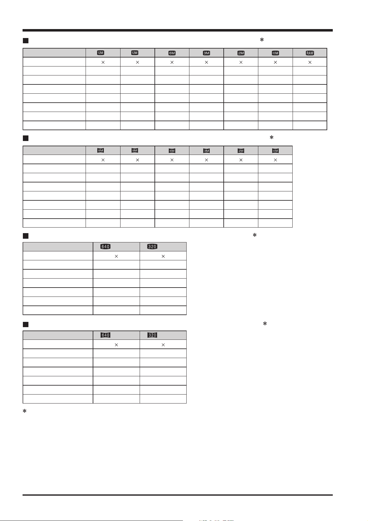
Standard number of frames per xD-Picture Card (Standard mode)
Quality setting
Number of recorded pixels
Image Data Size 2.5 MB 1.5 MB 630 KB 125 KB4.9 MB 780 KB 13 MB
DPC-16 (16 MB) 6
DPC-32 (32 MB)
DPC-64 (64 MB)
DPC-128 (128 MB)
DPC-256 (256 MB)
DPC-512 (512 MB)
F
4048 3040
3
6
12
26
52
105
N
4048 3040
12 20 50 247
2642101 497
52 84 204 997
105
211
2848 2136
10
169
339
2048 1536
19
40
81
162
325
651
1600 120025640 480
409
818
122
1997
3993
4048
3040
1
2
4
9
19
39
Standard number of frames per xD-Picture Card (Widescreen mode)
Quality setting
Number of recorded pixels
Image Data Size 1.8 MB 1.5 MB710 KB 135 KB3.5 MB750 KB
DPC-16 (16 MB) 8
DPC-32 (32 MB)
DPC-64 (64 MB)
DPC-128 (128 MB)
DPC-256 (256 MB)
DPC-512 (512 MB)
3968
F
2232
4
8
18
36
73
146
N
3968 2232
17 22 44 220
36 44 90 442
72 89 181 886
146
292
3200 1800
10
179
358
2304 1296
20
41
84
169
339
679
2048 115222768 432
362
725
109
1775
3549
Standard recording Times for xD-Picture Card (Standard mode)
Quality setting
Number of recorded pixels
DPC-16 (16 MB)
DPC-32 (32 MB)
DPC-64 (64 MB)
DPC-128 (128 MB)
DPC-256 (256 MB)
(30 fps)
640 480
18 sec.
36 sec.
73 sec.
147 sec.
296 sec.
9.8 min. 14.6 min.DPC-512 (512 MB)
(30 fps)
320 240
26 sec.
54 sec.
109 sec.
219 sec.
7.3 min.
Standard recording Times for xD-Picture Card (Widescreen mode)
Quality setting
Number of recorded pixels
DPC-16 (16 MB)
DPC-32 (32 MB)
DPC-64 (64 MB)
DPC-128 (128 MB)
DPC-256 (256 MB)
The number of available frames, recording time or file size varies slightly depending on the subjects photographed. Note
also that the difference between standard number of frames and the actual number of frames is greater for xD-Picture
Card with higher capacities.
(30 fps)
640 360
18 sec.
36 sec.
73 sec.
147 sec.
296 sec.
9.8 min. 18.9 min.DPC-512 (512 MB)
(30 fps)
320 184
34 sec.
70 sec.
141 sec.
283 sec.
9.4 min.
6

Fine Pix F810 SERVICE MANUAL
1.General
1-2.Explanation of Terms
AF/AE Lock: On the FinePix F810, pressing the shutter button down half way locks the focus
and exposure settings (AF and AE lock). If you want to focus on a subject that is
not centered in the frame or change the picture composition after the exposure is
set, you can obtain good results by changing the composition after the AF and AE
settings are locked.
Auto power save function:
DPOF: Digital Print Order Format
EV: A number denotes Exposure Value. The EV is determined by the brightness of
Frame rate (fps): The frame rate refers to the number of images (frames) that are photographed or
JPEG : Joint Photographics Experts Group
Motion JPEG: A type of AVI (Audio Video Interleave) file format that handles images and sound
PC Card: A generic term for cards that meet the PC Card Standard.
PC Card Standard: A standard for PC cards determined by the PCMCIA.
PCMCIA: Personal Computer Memory Card International Association (US).
Smear: A phenomenon specific to CCDs whereby white streaks appear on the image
WAVE: A standard format used on Windows systems for saving audio data. WAVE files
White Balance: Whatever the kind of the light, the human eye adapts to it so that a white object
Exif Print: Exif Print Format is a newly revised digital camera file format that contains a vari-
If the camera is not used in any way for 30 seconds, this function turns features
such as the LCD monitor off (sleep mode) to prevent battery depletion and the
waste of power when the AC power adapter is connected. If the camera is then
left unused for a further period, the Auto power save function turns the camera
off. This period can be set to 2 or 5 minutes on this camera.
z The Auto power off function does not operate in PC mode, during automatic
playback, or if it is disabled during setup.
DPOF is a format used for recording information on a storage media (image
memory card, etc.) that allows you to specify which of the frames shot using a
digital camera are to be printed and how many prints are made of each image.
the subject and sensitivity (speed) of the film or CCD. The number is larger for
bright subjects and smaller for dark subjects. As the brightness of the subject
changes, a digital camera maintains the amount of light hitting the CCD at a constant level by adjusting the aperture and shutter speed.
When the amount of light striking the CCD doubles, the EV increases by 1. Likewise, when the light is halved, the EV decreases by 1.
played back per second. For example, when 10 frames are continuously photographed in a 1-second interval, the frame rate is expressed as 10 fps.
For reference, TV images are displayed at 30 fps (NTSC).
A file format used for compressing and saving color images. The higher the compression rate, the greater the loss of quality in the decompressed (restored) image.
as a single file. Images in the file are recorded in JPEG format. Motion JPEG can
be played back by QuickTime 3.0 or later.
when there is a very strong light source, such as the sun or reflected sunlight, in
the photography screen.
have the “.WAV” file extension and the data can be saved in either compressed or
uncompressed format. Uncompressed recording is used on this camera.
WAVE files can be played back on a personal computer using the following software:
Windows: MediaPlayer
Macintosh: QuickTime Player
* QuickTime 3.0 or later
still looks white. On the other hand, devices such as digital cameras see a white
subject as white by first adjusting the color balance to suit the color of the ambient light around the subject. This adjustment is called matching the white balance.
ety of shooting information for optimal printing.
7
1.General
r
r
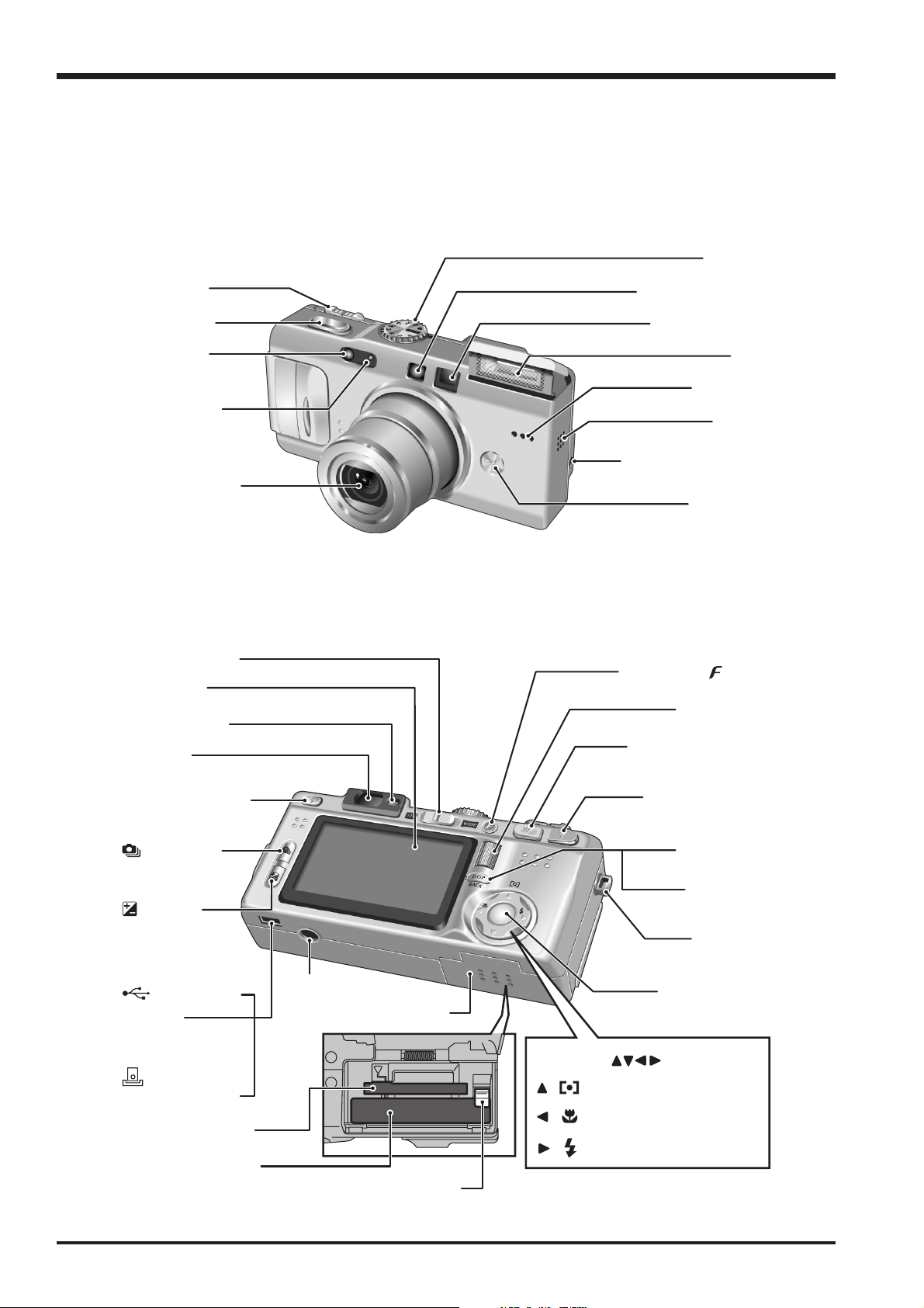
1-3.Name of External Components
Fine Pix F810 SERVICE MANUAL
Mode dial
Power switch
Shutter button
Flash control
sensor
Self-timer lamp
Lens (Lens cover)
WIDE/STD switch
LCD monitor
Viewfinder lamp
Viewfinder
AF-Assist Illuminato
Viewfinder window
Flash
Microphone
Speake
DC IN 5V (power input)
socket
C-AF button
Photo mode ( ) button
Command dial
W (wide-angle) button
Flash pop-up button
Continuous
shooting button
Exposure
compensation
button
(USB) socket
A/V OUT
(Audio / Visual
output) socket
Cradle
connection socket
xD-Picture Card slot
Battery compartment
Tripod mount
Battery cover
Battery release catch
T (telephoto) button
DISP (Display)
BACK button
Strap mount
MENU/OK button
4-direction ( ) button
/ (Photometry) button
/ (Macro) button
/ (Flash) button
button
8
Fine Pix F810 SERVICE MANUAL
2.Disassembly
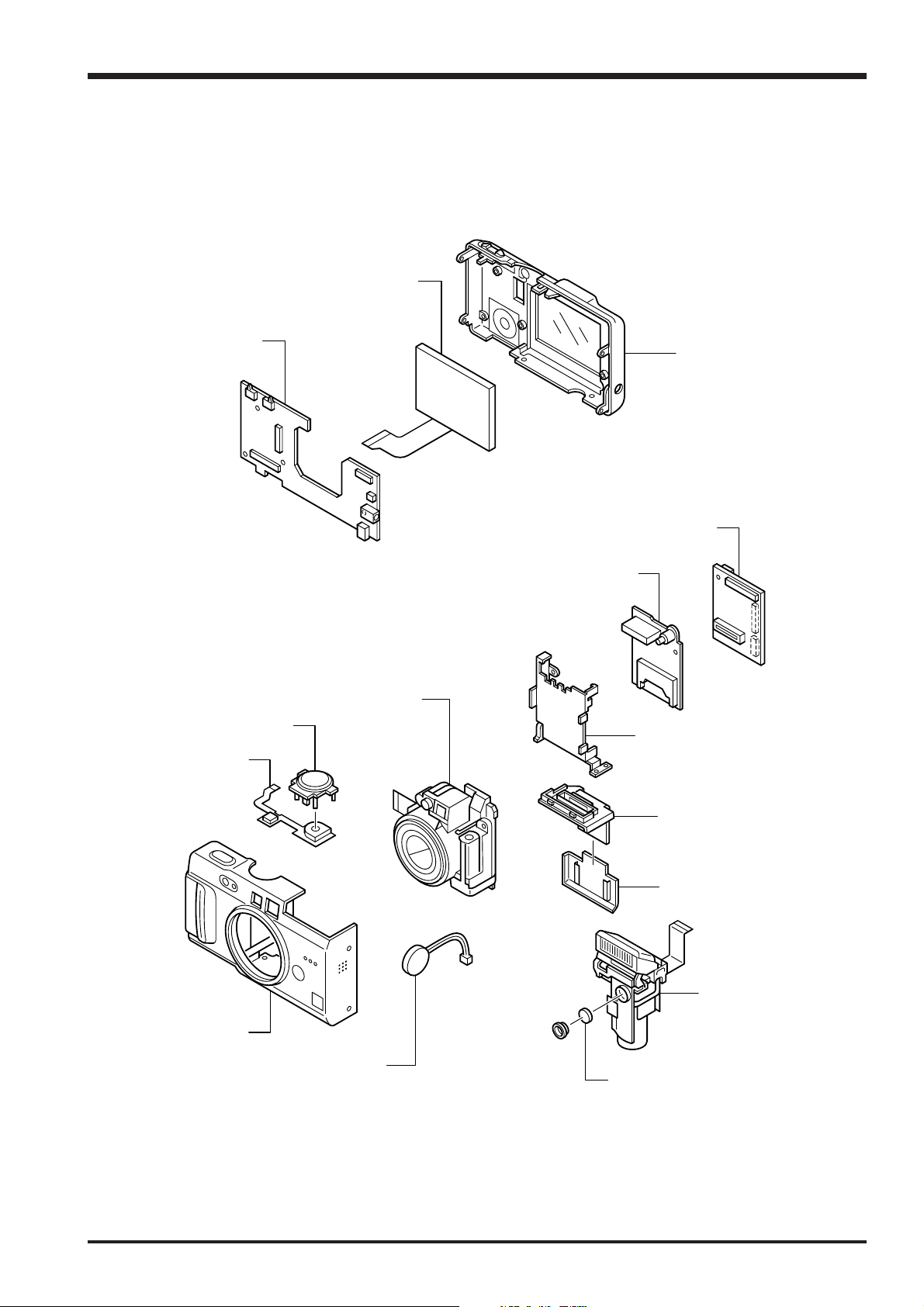
2-1.Name of Internal Parts
LCD CONST
2.Disassembly
REAR PWB ASSY
M DIAL ASSY
MODE FPC ASSY
REAR ASSY
MAIN PWB ASSY
DC PWB ASSY
LENS CONST
MAIN FRAME ASSY
FRONT ASSY
CABI BASE ASSY
BATTERY LID ASSY
STROBE CONST
SPEAKER
MICROPHONE
9
2.Disassembly
3
5
4
Fine Pix F810 SERVICE MANUAL
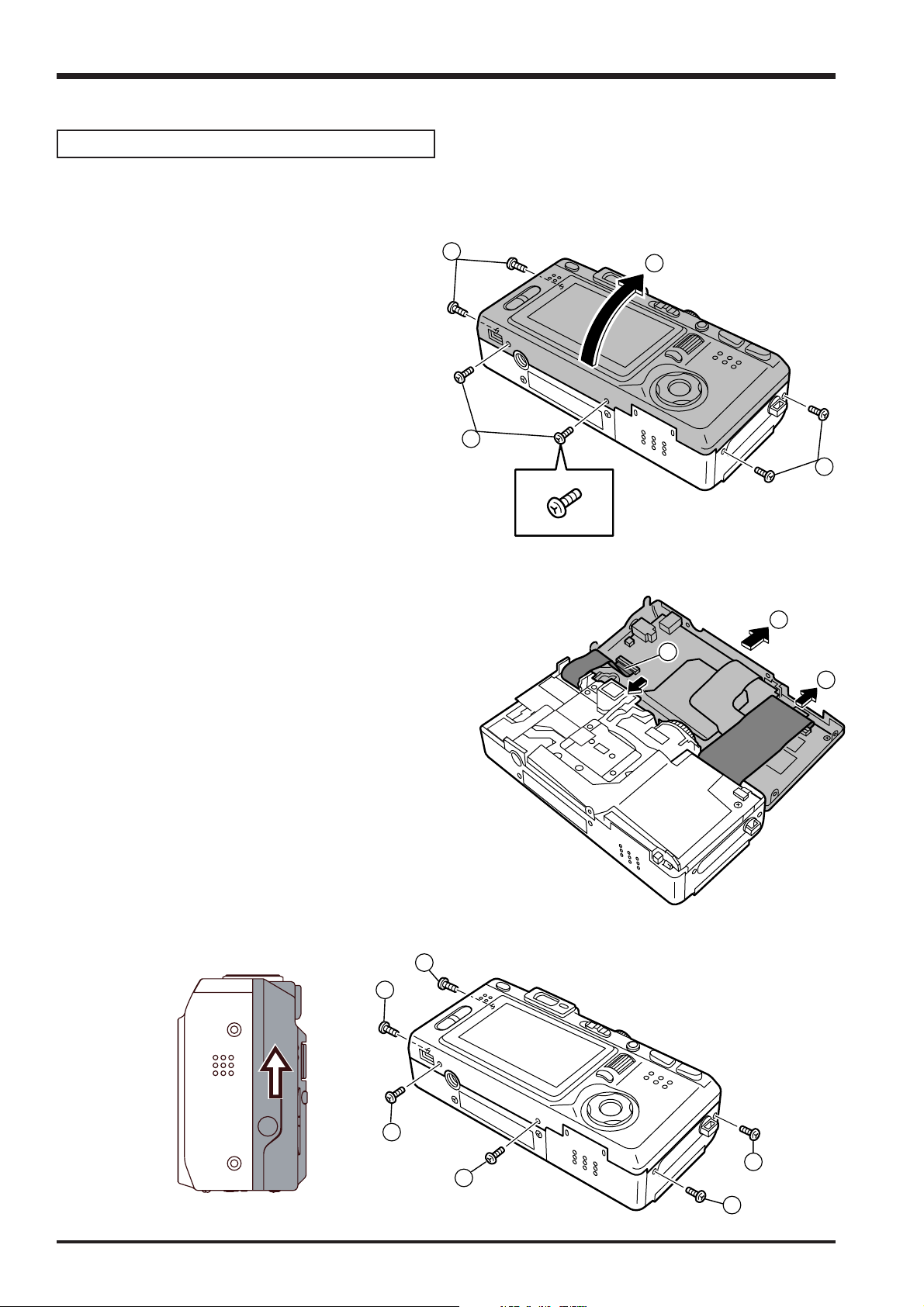
2-2.How to Disassemble the REAR ASSY
Remove in the order indicatd by circled numbers.
(1)Remove the 6 special shape screws.(3ULR 1.7X3.5)
*Because the screws are special shape,use the exclusive use jig driver(ZJ00538-100)
(2)Remove the R ASSY in the direction of the arrow.
(3)Remove the FPC(STOROBE CONST) in the direction of the arrow.
(4)Remove the FPC(MAIN PWB) in the direction of the arrow.
(5)Remove the R ASSY in the direction of the arrow.
1
1
2
1
[Attention when Reassemble]
Lift R-ASSY in the direction of the arrow, and stop the screw in (A)(B)(C)(D)(E)(F) order.
A
B
C
D
10
F
E
Fine Pix F810 SERVICE MANUAL
6
7
8
9
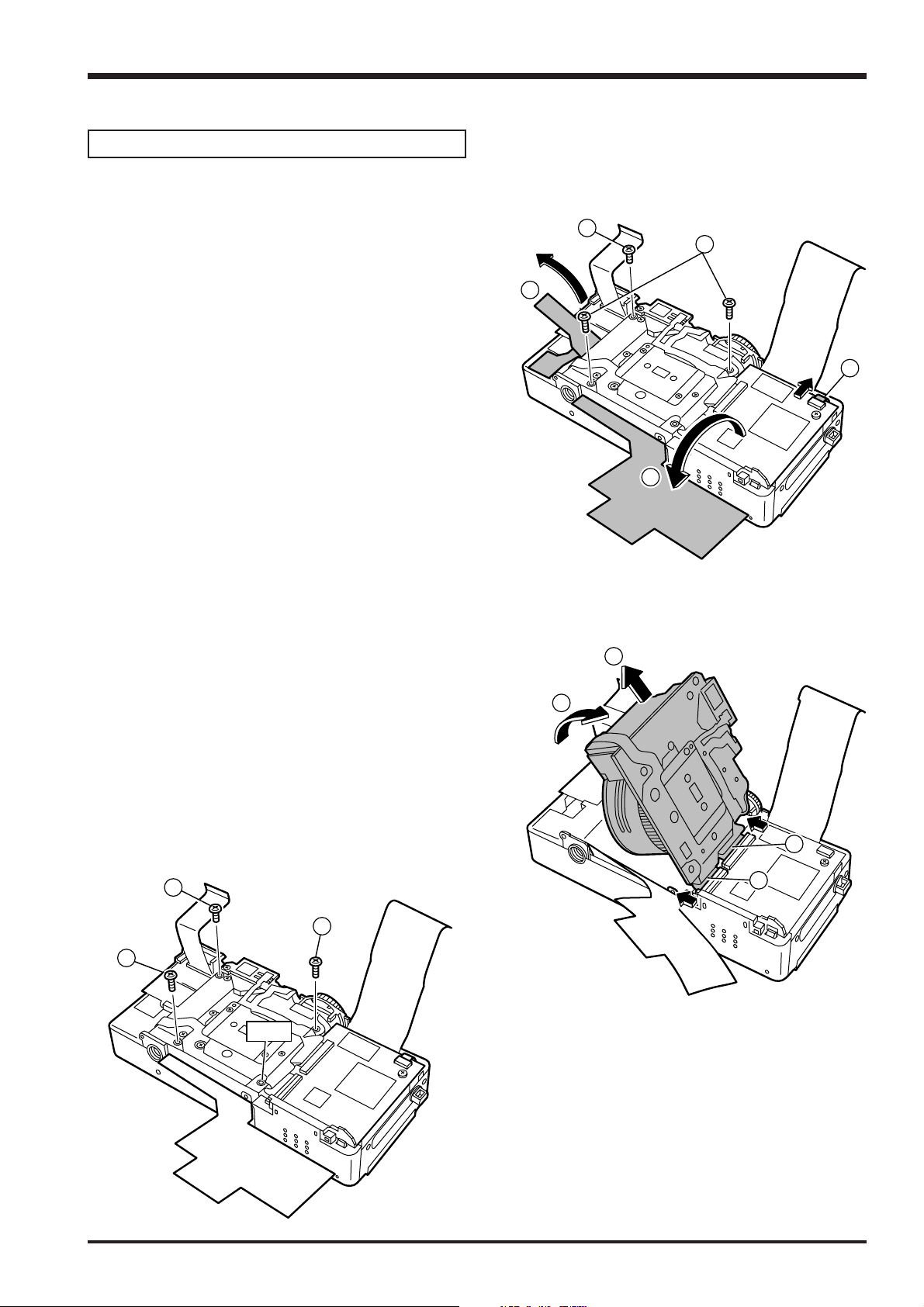
2-3.How to Disassemble the LENS CONST
Remove in the order indicatd by circled numbers.
(1)Remove the SHEET MAIN in the direction of the arrow.
2.Disassembly
(2)Remove the EMI SHEET(ST) in the direction of the arrow.
(3)Remove the FPC(MODE FPC) in the direction of the arrow.
(4)Remove the 2 screws.
(5)Remove the 1 screws.
(6)Lift the LENS CONST in the direction of the arrow.
(7)Remove the FPC(LENS UNIT) in the direction of the arrow.
(8)Remove the FPC(CCD FPC) in the direction of the arrow.
5
4
2
3
1
(9)Remove the LENS CONST in the direction of the arrow.
C
B
A
No screw
[Attention when Reassemble]
Please stop a screw in (A)(B)(C) order.
11
2.Disassembly
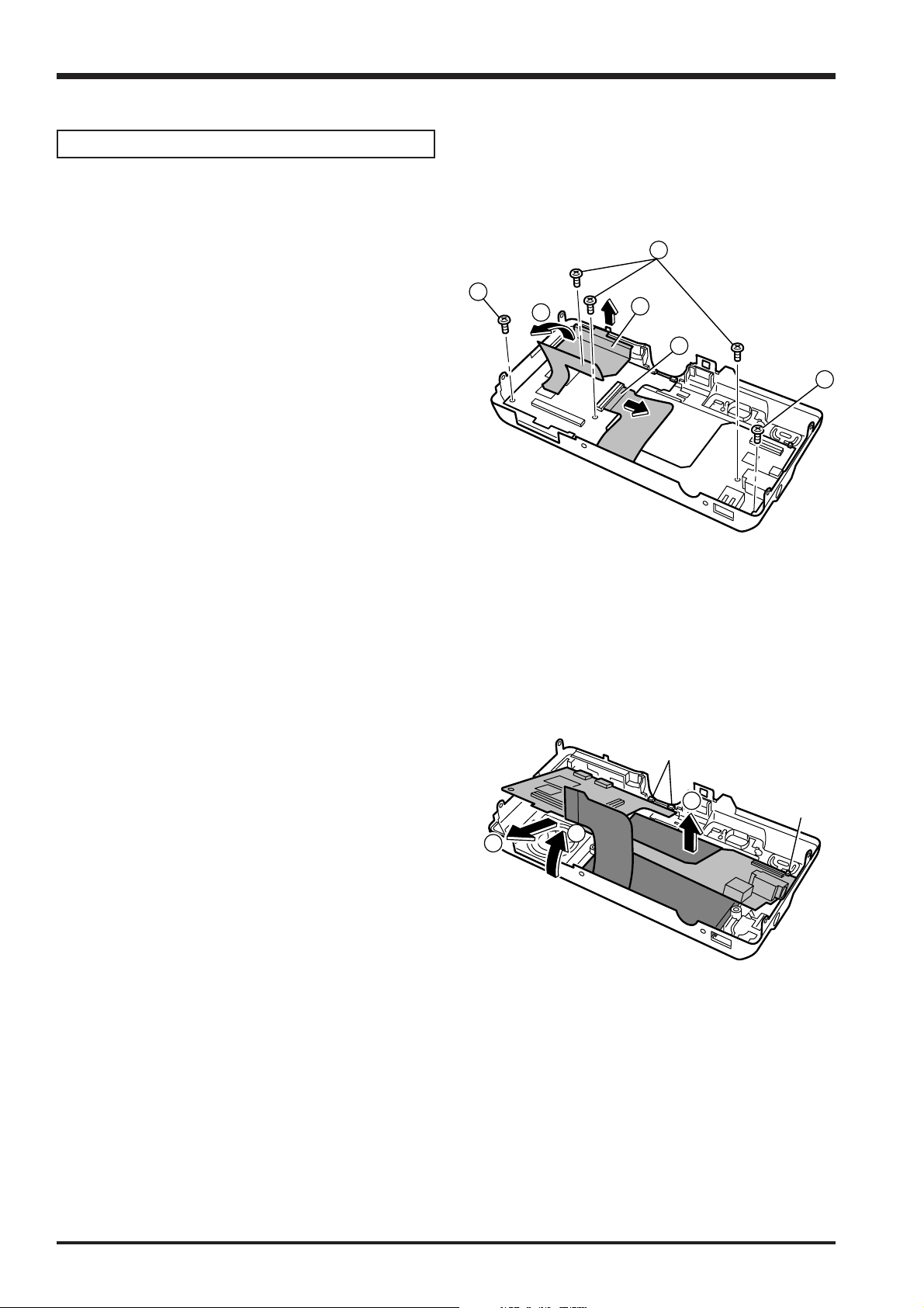
2-4.How to Disassemble the MAIN/DC BLOCK
Remove in the order indicatd by circled numbers.
(1)Remove the 6 special shape screws.(3ULR 1.7X3.5)
*Because the screws are special shape,use the exclu-
sive use jig driver(ZJ00538-100)
(2)Open the Battery Cover in the direction of
the arrow.
Fine Pix F810 SERVICE MANUAL
4
(3)Remove the hook of MAIN FRAME(2 place).
(4)Remove the MAIN/DC BLOCK in the direction
of the arrow.
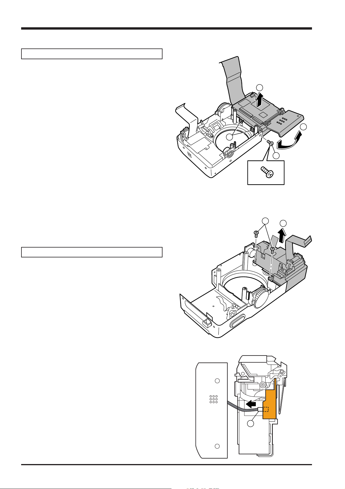
2-5.How to Disassemble the STROBE CONST
Remove in the order indicatd by circled numbers.
(1)Remove the 2 screws.
(2)Remove the STROBE CONST in the direction of the
arrow.
2
3
1
1
2
(3)Remove the WIER HERNES(SPEAKER) in the direc-
tion the arrow. (STROBE CONST)
12
3
Fine Pix F810 SERVICE MANUAL
3
4
5
7
6
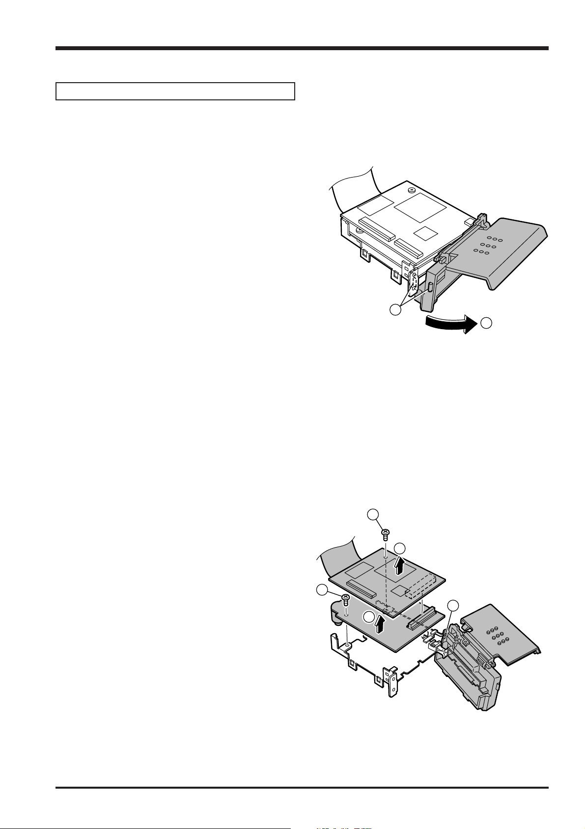
2-6.How to Disassemble of MAIN/DC PWB
Remove in the order indicatd by circled numbers.
(1)Remove the hook of MAIN FRAME(1 place).
(2)Move the Battery Cover Block in the direction of the arrow.
2.Disassembly
1
2
(3)Remove the 1 screw.
(4)Remove the MAIN PWB ASSY in the direction of the arrow.
(5)Remove the 1 screw.
(6)Remove the DC PWB ASSY in the direction of the arrow.
(7)Remove Battery Cover Block from the hook of MAIN FRAME.
13
2.Disassembly
2-7.How to Disassemble of REAR PWB ASSY
Remove in the order indicatd by circled numbers.
(1)Remove the SHEET (REAR) in the direction of the arrow.
(2)Remove the 3 screws.
(3)Remove the 2 screws.
3
(4)Remove the SHEET FPC in the direction of the arrow.
(5)Remove the LCDFPC in the direction of the arrow.
Fine Pix F810 SERVICE MANUAL
2
1
4
5
3
(6)Move the REAR PWB in the direction of the arrow.
(7)Remove the REAR PWB in the direction of the arrow.
(8)Remove the LCD UNIT in the direction of the arrow.
[Attention when Reassemble]
Confirm whether REA PWB hangs in the hook of REAR ASSY.(3 place)
7
Hook
8
6
Hook
14

Fine Pix F810 SERVICE MANUAL
2-8.How to Disassemble of CCD FPC ASSY
No do disassembly because the assembled accuracy is necessary.
2.Disassembly
15
2.Disassembly
A
2-9.Location of Sheet Parts
[Attention when Reassemble.]
Do not use removed “Sheet Parts”.
Use surely new parts at the time of reassembly.
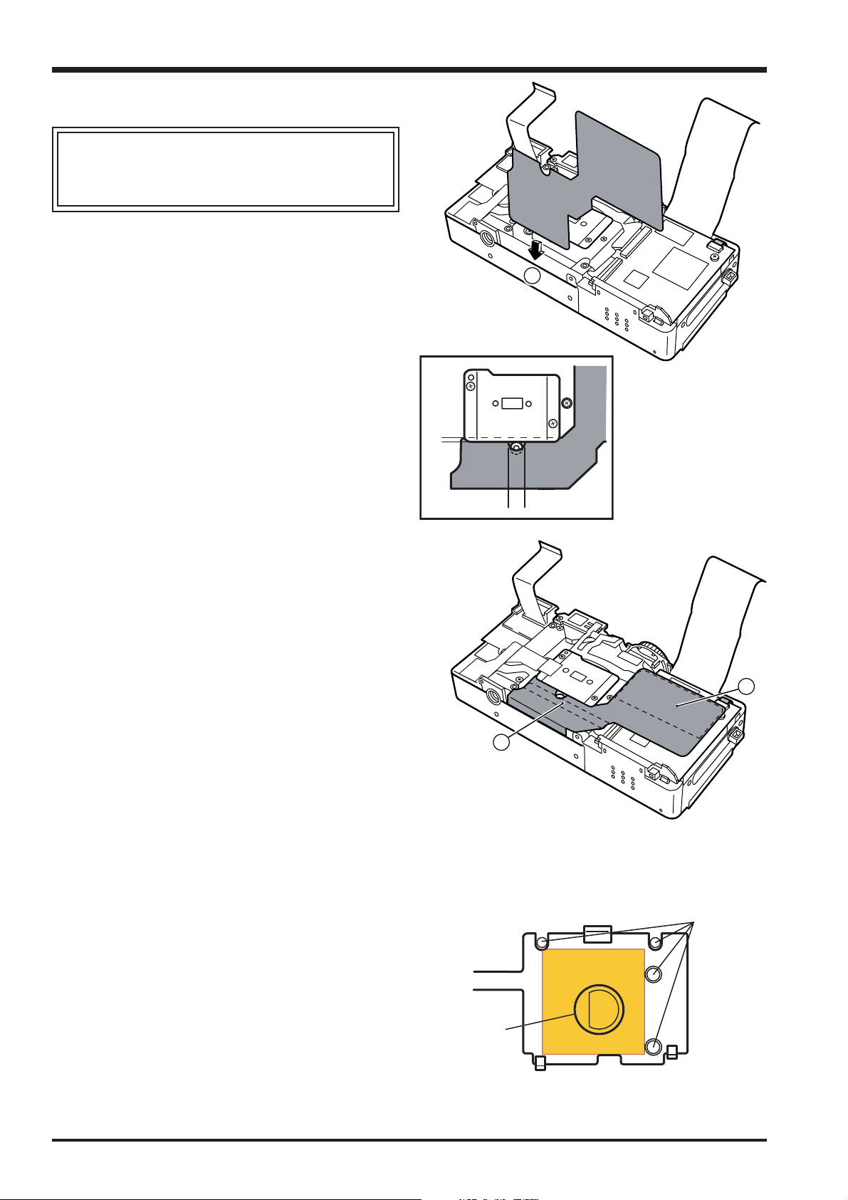
2-9-1.SHEET (MAIN ) (FZ05961-100)
Fine Pix F810 SERVICE MANUAL
(1)Insert SHEET(MAIN) between F ASSY and LENS
UNIT.
(2)Insert the edge of SHEET(MAIN) under CCD PLATE.
*(A)Horizontal direction
Match the edge where the incision and LENS UNIT of
SHEET(MAIN) are round.
*(B)Vertical direction (amount of insertion)
Position that lightly does slide and stops.
(3)Put bonding seat part(C)(D) of SHEET(MAIN).
1
B
A
C
2-9-2.MODE SHEET (BB17137-100)
Put MODE SHEET to close hole (B) of MODE FPC
bottom.(MODE DIAL side)
*Do not get on on the pin (four places).
D
B
16
Fine Pix F810 SERVICE MANUAL
B
A
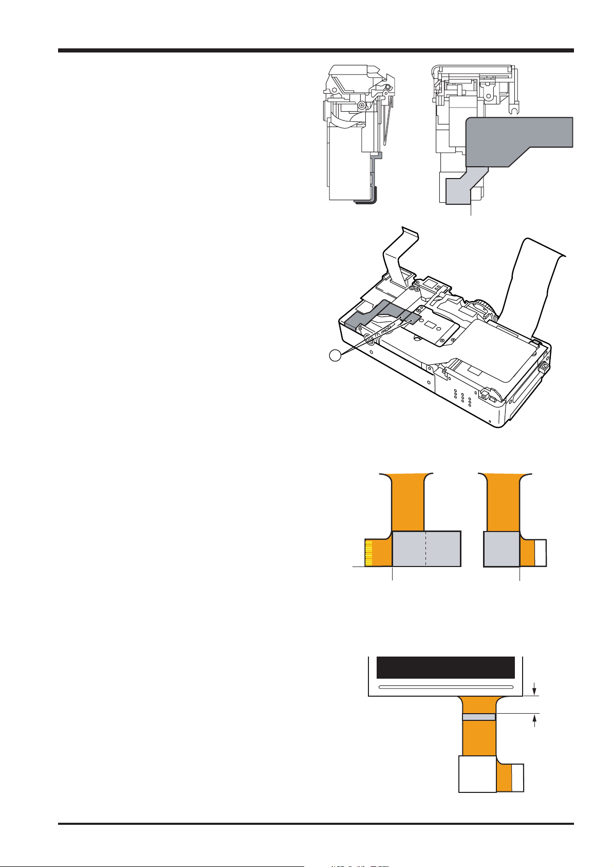
2-9-3.EMI SHEET (ST) (FZ06008-100)
(1).Put EMI SHEET (ST) under STROBE CONST.
*Put according to edge (B) of the frame, and turn
on the bottom side.
*EMI SHEET (ST) is included in STROBE CONST.
(2).Put EMI SHEET(ST) on CCD-PLATE.
*Putting point (A) must not float.
2.Disassembly
2-9-4.EMI SHEET(LCD)(FZ05861-100)
(1)Put EMI SHEET(LCD) on the terminal side side of
FPC(LCD CONST).
*The putting starting position is an edge of FPC(A)(B).
(2)Turn EMI SHEET(LCD), and put on the back side
of FPC(LCD CONST).
*The putting standard is an edge of FPC (C).
*Putting error margin "(A)(B)(C)"; Within 1mm from edge
of FPC.
2-9-5.SHEET(LCD FFC)(FZ06068-100)
(1)Put SHEET(LCD FFC) on FPC(LCD CONST).
B
A
C
9mm
*The putting point is 9mm from the LCD edge.
17
2.Disassembly
A
A
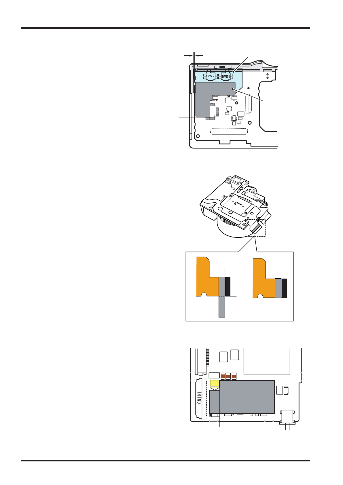
2-9-6.EMI SHEET(REAR)(FZ06007-100)
Put EMI SHEET (REAR) on the mode switch side of
REAR PWB.
*The putting position of the vertical direction is (A) be-
tween "Bottom of SW601/654" and "Under edge of
IC804".
*Put it so as not to hang in SW601/654.
*A horizontal putting position is within 1mm from the edge
of "Inner cabinet of R ASSY".
Fine Pix F810 SERVICE MANUAL
B
MODE SHEET
EMI SHEET
2-9-7.EMI SHEET(CCD FPC)(FZ06004-100)
(1)Put EMI SHEET(CCD FPC) on the terminal side side
of CCD FPC(LCD CONST).
*The putting starting position is an edge of CCD
FPC(A)(B).
(2)Turn EMI SHEET(CCD FPC), and put on the back side
of CCD FPC.
*The putting standard is an edge of CCD FPC (C).
2-9-8.EMI SHEET(MAIN)(FZ06005-100)
A
B
C
Put EMI SHEET(MAIN) on the MAIN PWB ASSY.
*The putting starting position is an edge of C102(A)(B).
*EMI SHEET(MAIN) must not come in contact with the
terminal of C102.
18
C102
IC206
IC102
B
Fine Pix F810 SERVICE MANUAL
C
A
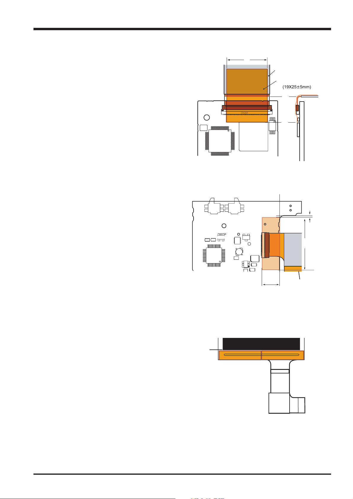
2-9-9.POLYIMIDE TAPE 1
M-R FPC ASSY is attached in MAIN PWB ASSY, and
the polyimide tape is stuck on it.
2.Disassembly
M_R FPC ASSY
*ZS00024-100(polyimide tape PIT- 652S) is cut in
19X25mm and it uses it.
*It puts it with M-R FPC ASSY bent from white line edge
(B).
*It matches it to side (A) of IC351 of MAIN PWB ASSY.
*Width (C) of the polyimide tape must not exceed it to
the width of M_R FPC ASSY.
2-9-10.POLYIMIDE TAPE 2
LCD FPC is attached in REAR PWB ASSY, and
the polyimide tape2 is stuck on it.
*ZS00024-100(polyimide tape PIT- 652S) is cut in
25X9mm and it uses it.
SW654
Polyimide Tape
B
A
IC351
A
SW601
B
25mm
*Put it based on inner edge (A and B) of REAR PWB..
*Confirm the terminal of CN803 has been covered.
2-9-11.POLYIMIDE TAPE 3
Polyimide tape3 is stuck on the surface of LCD CONST.
*Cut and use ZS00024-100 (polyimide tape PIT652).
*Be not laid in the LCD display part (A).
LCD FPC
9mm
19
2.Disassembly
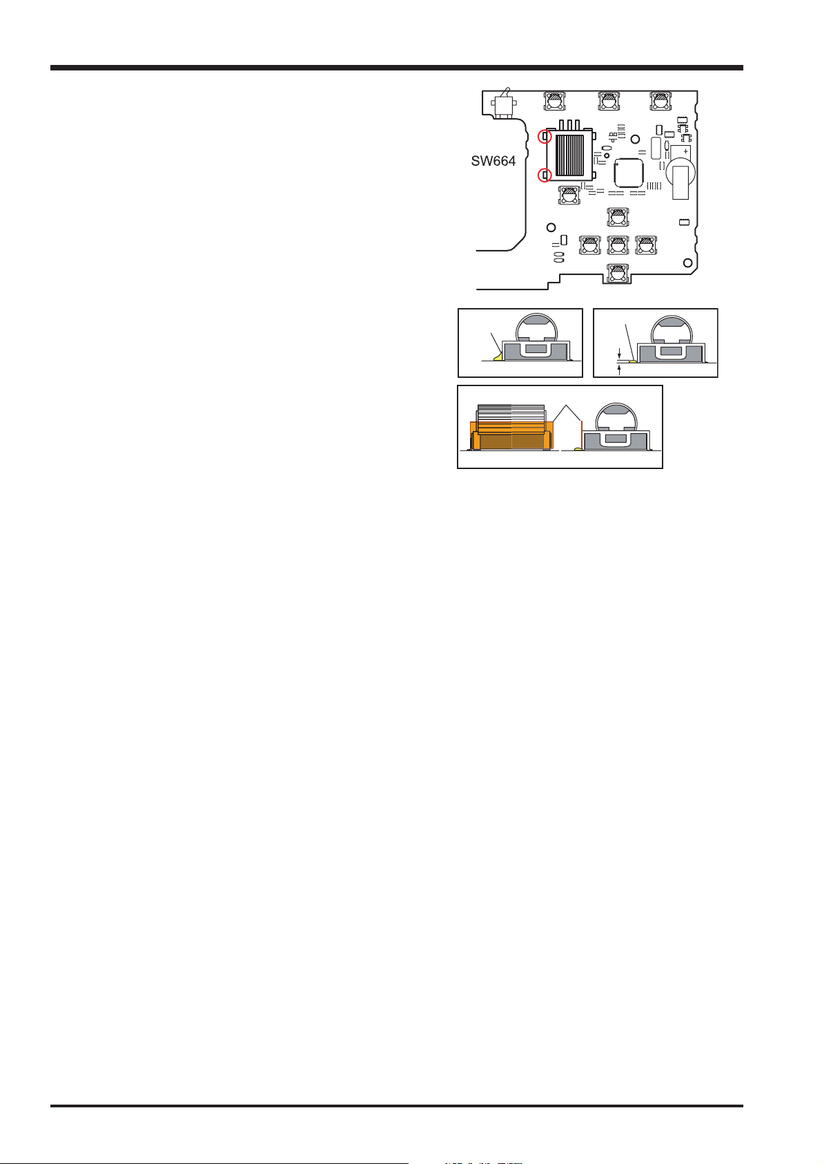
2-10.Electronic part installation specification
2-10-1.ROTARY ENCODER SWITCH (FZ05596-100)
Adjust the height of the solder part of ROTARY
ENCODER SWITCH (2-place on the LCD side)
to 1mm or less (A).
*Solder rises to the side of ROTARY ENCODER
SWITCH in usual work (NG).
Fine Pix F810 SERVICE MANUAL
*The polyimide tape(B) is put on the ROTARY EN-
CODER SWITCH side to prevent it and the solder
works. (removed after soldering)
*Cut and use Z00024-100 (polyimide tape PIT- 652S).
NG
OK
A
B
20

Fine Pix F810 SERVICE MANUAL
3.Schematics
3.Circuit Diagrams
3-1.Cautions
Precautions in parts replacement
Do not reuse detached electronic components. Use only new components.
The negative side of tantalum capacitors is weak against heat. Handle with care.
With the exception of Chemical capacitor and tantalum capacitors, the voltage of capacitors of a 50V or lower withstand
voltage is not labeled.
Unless specified, electronic component resistance is 1/16W.
K = 1000 , M = 1000 K
3-2.Names and Functions of Basic Blocks
Board Name Block Name Function
CCD FPC CCD BLOCK CCD ouput(IC1)
MAIN PWB CAM BLOCK Analog to Digital conversion of CCD Output(IC103)
CCD V_Drv(IC102) OFD/RG/BIAS(IC101)
PROCESS BLOCK Signal processing/System/Analog to Digital conversion of Audi/LCD backlight control(IC206)
USB(IC301) Partner(IC352) MEMORY SIP(IC351)
MOTOR BLOCK AF/Zoom/Iris/Shutter drive(IC151)
DC PWB DCDC BLOCK Each power generation(IC401) Battery charge control (IC502)
REAR PWB AUDIO BLOCK Audio signal processing (IC701)
VIDEO BLOCK Video signal processing NTSC/PAL (IC751)
IPS BLOCK Power_ON / Flash processing (IC601)
KEY BLOCK Operation SW(CAM<->PB / TELE<->WIDE / R / L / U / D / OK / BACK / EXP / DRIVE
WIDE / NOMAL / SEL_A / SEL_B)
LCD BLOCK LCDsignal processing (IC804)
LCD const LED back light
MODE FPC Operation SW(S1/S2 MODE)
STROBE CONST STOROBE BLOCK Flash charge and luminescence Operation SW(C_AF)
3-3.Explanation of Functions of Important Blocks
It is editing it.
21

3.Schematics
MEMO
Fine Pix F810 SERVICE MANUAL
22
Fine Pix F810 SERVICE MANUAL
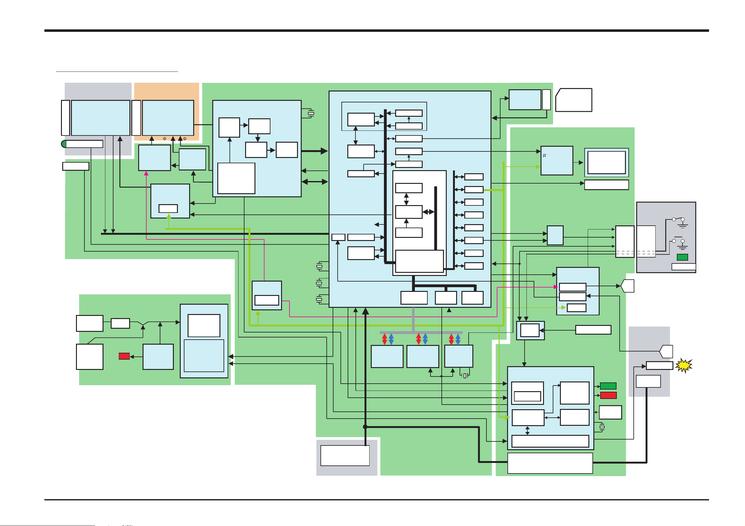
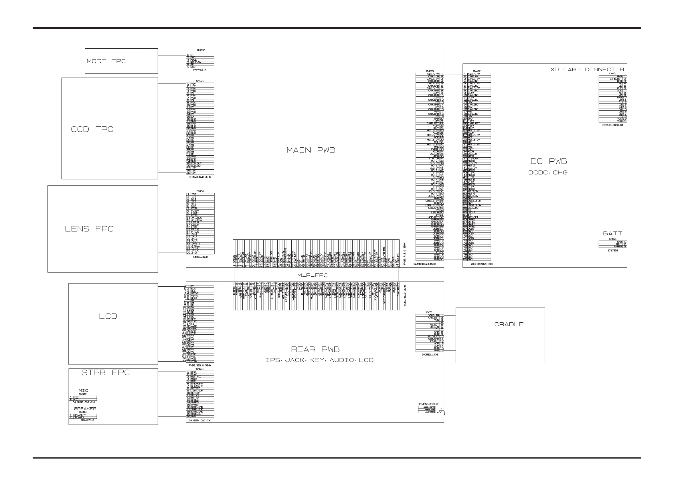
FinePix F810 Block Diagram
LENS UNIT
CCD PWB ASSY
MAIN PWB ASSY
DCDC PWB ASSY
MODE DIAL
REAR PWB ASSY
CRADLE
STROBE
CONST
FinePix F810 Block Diagram
3.Schematics
3-4.Block Diagram
LENS UNIT
4xZOOM LENS
ier
IRIS 10Step
WIDE/TELE Variable
LENS Barr
AF ASSIST LED
P-TR
Zoom HP
Zoom position
Focus HP
DCDC PWB ASSY
DC IN
5V
BATT
NP-40
FUSE
SELF TIMER
CCD PWB ASSY
WHA-CCD
MS3895
1/1.7inch
6.3million pixels
Optical LPF
OFD/RG
BIAS
Cont Pulses
NJM2125R
OFD_CONT
Charge IC
LED
M62248
IC502
CCDIN
IC1
V
H
V Drv
MD2174
IC101
IC102
V Pulse
Motor Drv
M50239HP
IC151
6ch
CTL
SHT Pulse
DC/DC Block
DC/DC IC
AN30212A
5ch
1.5V
3.3V
5V
CCD16V,8V,11V
ETC.
MAIN PWB ASSY
ACS AD80057
3.3V Operation
CDS
TG
(Programble)
IC401
ADC
14bit
Digital
Gain
CCD_ON,
PWCTL
3.3V_ON
Gray
Code
Focus,Iris,Zoom Pulse
Detect system
EVR
3ch
CTL
SIO_2
(EVR_SIO)
IC103
XTAL
CX_101F
36.00MHZ
CCD[13-0]
RVRESET,
OCONT
VI,HI,ADCK,
STB,LD,DI,
CLK,WAIT
XTAL
CX_101F
48.00MHZ
XTAL
CX_101F
27.00MHZ
XTAL
CX_101F
24.54MHZ
UCS2 LIBRA 3.3V Operation
IBFC
RECC
YCPRO
CGEN
Audio(Seriul)
Audio(A/D)
A/D
JPEG
Partner
IC352
AUTO
CCDIF
MEDIA
TFDC
ENCD
TX 49 CPU Core
DEBUG I/F
CPU Core
l-cache 16k
BUS Cont
SDRAMC
DMAC
I/O Buffer
MEMORY SIP
SDRAM
IC351
256Mb x32
FLASH 8MB
IC206(MAIN PWB)
96MHz
US
l B
Periphera
Internal
eDRAM A
SY
BAT_V PWR_SW
IPS_ACT STRB_CC
RESET
Internal
eDRAM B
USB2.0
IC301
WDT
SIO
USB
MFT
ICU
DAC
PORT
CLKC
XTAL
CX_101F
24.00MHZ
AU DA
xD Card
Slot
(20pin)
LCDDAT0-7
LCD_CLK
LCD_HD,LCD_VD
LCD_RESET
SIO_1
(U2_SIO)
BL_ON
VIDEO_ON
A_MUTE
L_MUTE
BEEP
MIC_IN
SIO_1
(Us_SIO)
SEL
SIO_1 (U2_SIO)
IPS
AN30203
Power on
Reset
CTL
xD Picture Card
DR_SW
LCD IC
PD65942
IC804(REAR PWB)
Video
VBS_OUT
Driver
IC751
AUDIO IC
BP3602
IC701(REAR PWB)
SP_AMP
MIC_AMP
IC601(REAR PWB)
LED
DRIVE
X3
REAR PWB ASSY
LCD Panel
2.13inch
BL LED x4
AUDIO_OUT
14pin
MULTI
USB I/F
CTL
POWER SW
RTC
LED_G
LED_R
BATT
Backup
32.768kHz
CRADLE
14pin
MULTI
USB I/F
SPEAKER
STROBE
CONST
STRB-Xe
C_AF SW
CRD_SW
LED
DC IN 5V
MIC
MODE DIAL
RELEASE SW(S1/S2)
MODE DIAL
STROBE CTRL
CAM/PB SW TELE/WIDE/R/L/D/U SW
OK/BACK/F SW EXP/DRIVE SW
WIDE/NOMAL SEL_A,SEL_B
23
3.Schematics
3-5.Overall
Fine Pix F810 SERVICE MANUAL
17
24
Fine Pix F810 SERVICE MANUAL
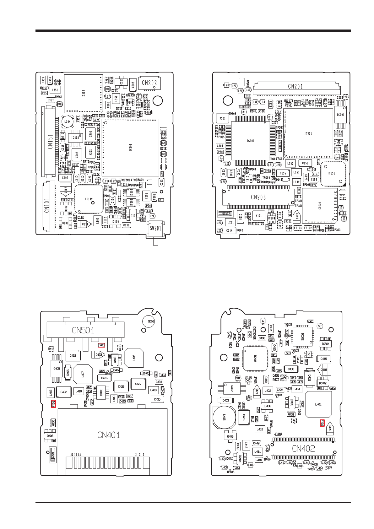
3-6.Mounted Parts Diagrames
3-6-1.MAIN PWB ASSY
3.Schematics
SIDE-A
3-6-2.DC PWB ASSY
SIDE-B
SIDE-A
SIDE-B
25
3.Schematics
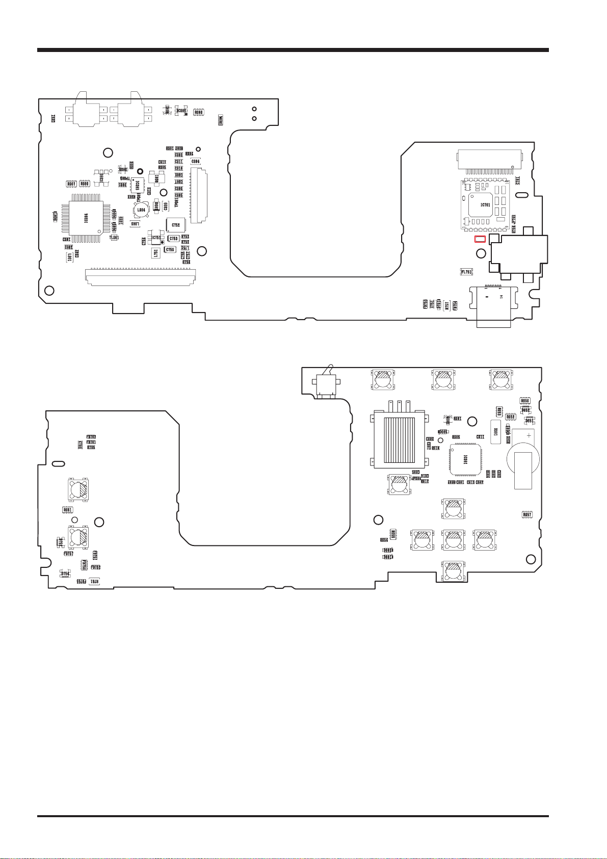
3-6-3.REAR PWB ASSY
Fine Pix F810 SERVICE MANUAL
SW654
SW601
CN801
803
CN
SIDE-A
CN601
F751
J751
CN751
SW663SW653
SW657SW658
SIDE-B
SW652
SW651
SW664
SW656
SW662
SW660 SW655
SW661
SW659
BT601
26
Fine Pix F810 SERVICE MANUAL
3.Schematics
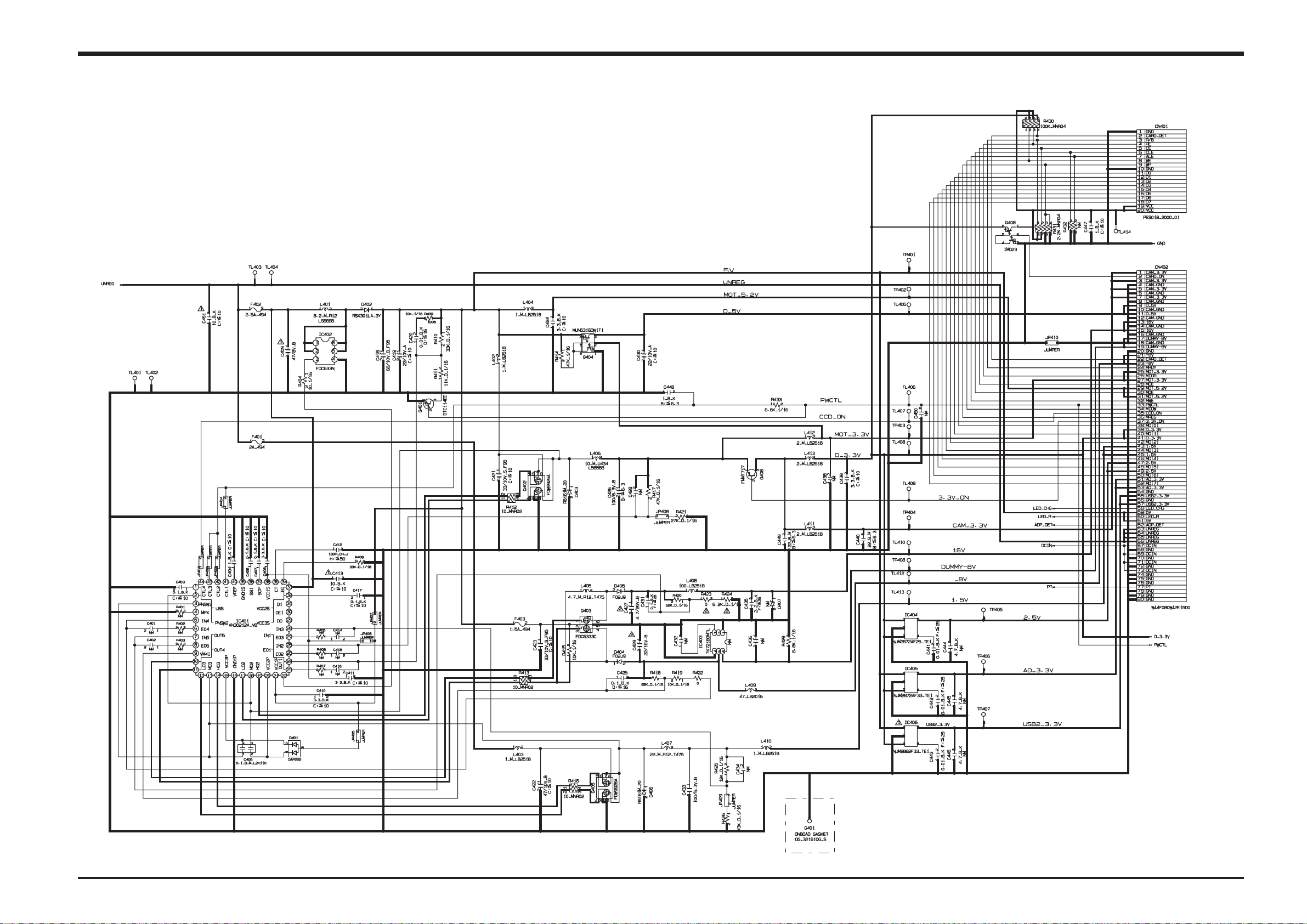
3-7.Circuit Diagrames
3-7-1.DCDC
27
 Loading...