

FUJIFILM FinePix F610 SERVICE MANUAL
DIGITAL CAMERA
F610
SERVICE MANUAL
US/CA/EU/EG/GE/AS-Model
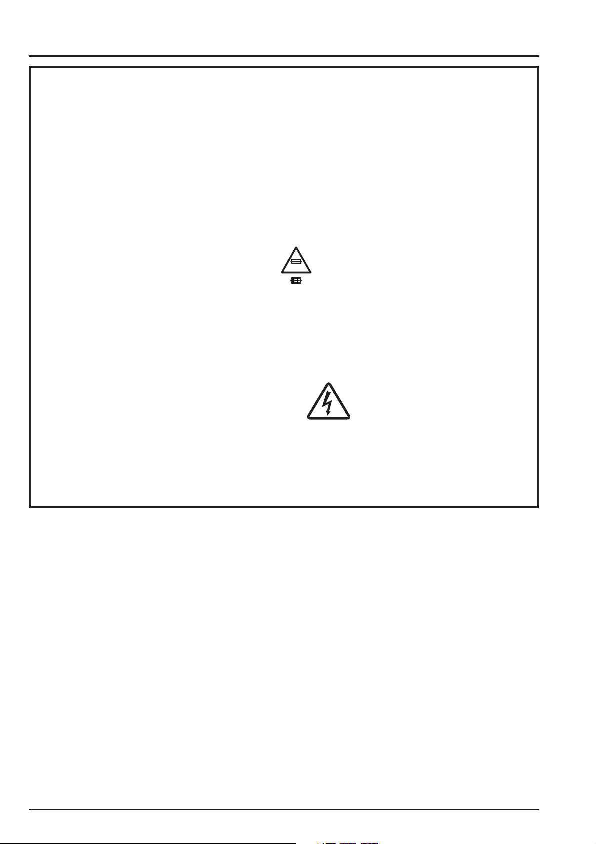
WARNING
THE COMPORNENTS IDENTIFIED BY THE MARK “ ” ON THE SCHEMATHIC
DIAGRAM AND IN THE PARTS LIST ARE CRITICAL FOR SAFETY.
PLEASE REPLACE ONLY BY THE COMPONENTS SPECIFIED ON THE SCHEMATHIC
DIAGRAM AND IN THE PARTS LIST.
IF YOU USE WITH PART NUMBER UN-SPECIFIED, IT MAY RESULT IN A FIRE AND AN
ELECTORICAL SHOCK.
Ref.No.:ZM00527-103
FUJI PHOTO FILM CO.,LTD.
Printed in Japan 2004.2(T.S.)
FinePix F610 (US/EU/EG/GE/CA/AS) SERVICE MANUAL
SAFETY CHECK-OUT
After correcting the original problem, perform the following
safety check before return the product to the customer.
1. Check the area of your repair for unsoldered or poorly
soldered connections. Check the entire board surface
for solder splasher and bridges.
2. Check the interboard wiring to ensure that no wires are
“pinched” or contact high-wattage resistors.
3. Look for unauthorized replacement parts,
particularly transistors, that were installed during a
previous repair. Point them out to the customer and
recommend their replacement.
4. Look for parts which, though functioning, show obvious
signs of deterioration. Point them out to the customer and
recommend their replacement.
5. Check the B + voltage to see it is at the values specified.
6. Make leakage - current measurements to determine
that exposed parts are acceptably insulated from the
supply circuit before returning the product to the customer.
7. CAUTION: FOR CONTINUED
PROTECTION AGAINST FIRE
HAZARD, REPLACE ONLY WITH
SAME TYPE 2.5 AMPERES 125V
FUSE.
RISK OF FIRE-
2.5A125V
2.5A125V
8.
WARNING!
HIGH VOLTAGE
REPLACE FUSE
AS MARKED
ATTENTION: AFIN D'ASSURER
UNE PROTECTION
PERMANENTE CONTRE LES
RISQUES D'INCENDIE,
REMPLACER UNIQUEMENT
PAR UN FUSIBLE DE MEME,
TYPE 2.5 AMPERES, 125 VOLTS.
WARNING:
TO REDUCE THE ELECTRIC
SHOCK, BE CAREFUL TO
TOUCH THE PARTS.
2

FinePix F610 (US/EU/EG/GE/CA/AS) SERVICE MANUAL
CONTENTS
Page Page
1. General
Table of Contents
4. Adjustment
1-1. Product specification.......................................................... 4
1-2. Explanation of Terms ......................................................... 6
1-3. Names of External Components....................................... 7
2. Disassembly
2-1. Names of internal Components ........................................ 8
2-2. Removing R PANEL ASSY................................................ 9
2-3. Removing B/W LCD and KEY PWB ASSY.................... 10
2-4. Removing MODE DIAL .................................................... 11
2-5. Removing DSC BLOCK ................................................... 12
2-6. Removing LCD CONST and LENS CONST ..................13
2-7. Removing CAM PWB ASSY............................................ 13
2-8. Removing MAIN PWB ASSY...........................................14
2-9. Removing BATTERY LID ASSY ..................................... 14
2-10. Removing DCST PWB CONST ..................................... 14
3. Schematic
3-1. Cautions ............................................................................. 15
3-2. Basic block name and function explanation .................. 15
3-3. Functions of Primary Blocks ...........................................16
3-3-1. Technical Outline ..................................................16
3-3-2. CAM Board Block Functions ................................16
3-3-3. MAIN Board Block Functions...............................16
3-3-4. DCST Board Block Functions ..............................16
3-4. Block Diagram................................................................... 17
3-5. Overall Connections......................................................... 18
3-6. Board mounting diagram ................................................. 19
3-6-1. Printed wiring board of MAIN PWB ASSY .........19
3-6-2. Printed wiring board of DCST PWB CONST ...... 20
3-6-3. Printed wiring board of CAM PWB ASSY ........... 21
3-6-4. Printed wiring board of CCD PWB ASSY........... 22
3-6-5. Printed wiring board of KEY FPC PWB ASSY... 23
3-7.Circuit diagram .................................................................. 24
3-7-1. XE BLOCK Circuit ................................................. 24
3-7-2. JACK BLOCK Circuit ............................................24
3-7-3. VIDEO BLOCK Circuit .......................................... 24
3-7-4. DC/DC BLOCK Circuit .......................................... 25
3-7-5. PROCESS BLOCK Circuit .................................... 26
3-7-6. CAM BLOCK Circuit..............................................27
3-7-7. MOTOR BLOCK Circuit ........................................28
3-7-8. CHG BLOCK Circuit..............................................29
3-7-9. STRB BLOCK Circuit ............................................30
3-7-10. LCD BLOCK Circuit ............................................. 31
3-7-11. POWER ON BLOCK Circuit ...............................32
3-7-12. KEY BLOCK Circuit ............................................. 33
3-7-13. CCD BLOCK Circuit............................................34
3-7-14. AUDIO BLOCK Circuit ........................................34
4-1. Important point Adjustment when Replacing Major Parts.... 35
4-2. Measuring Instruments Used ..........................................35
4-3. Use Jig list.........................................................................35
4-4. Calibration method of pattern box..................................36
4-5. Various downloading software decompressions,
preservation methods, and notes ...................................36
4-6. Adjusting soft installation ................................................37
4-6-1. Installation of DSC jig driver................................37
4-6-2. Adjusting soft initiation method ...........................37
4-7. Initial Settings of the Adjustment Software ...................38
4-8. Starting the Adjustment Software................................... 41
4-9. [R] : Flash memory reset .................................................44
4-10. [F4] : CCD Defect Data Input........................................ 46
4-11. [F5] : CAM Adjustment ................................................... 48
4-12. [F6] : AF Adjustment ......................................................51
4-13. [F7] : Flash Adjustment .................................................54
4-14. [F1] : Battery Voltage Adjustment ................................ 56
4-15. [F3] : LCD Adjustment ...................................................60
4-16. [F2] : Display Panel Adjustment ...................................62
4-17. [F11] : Video Adjustment...............................................64
4-18. [F12] : End Setting ......................................................... 66
4-19. [F8] : Firmware Download ............................................. 70
5. Inspection
5-1. Required Measuring Equipment .....................................72
5-2. Connection of Measuring Equipment............................. 72
5-3. Inspection and Factory Settings .....................................72
6. Parts List
6-1. Packing and Accessories ................................................ 74
6-1-1. Packing and Accessories (EG-MODEL)............. 74
6-1-2. Packing and Accessories (US-MODEL) .............75
6-1-3. Packing and Accessories (CA-MODEL) .............76
6-1-4. Packing and Accessories (EU-MODEL) .............77
6-1-5. Packing and Accessories (GE-MODEL)............. 78
6-1-6. Packing and Accessories (AS-MODEL) .............79
6-2. Mechanical parts ..............................................................80
6-2-1. Mechanical parts (US/CA-MODEL).....................80
6-2-2. Mechanical parts (EU/EG/GE/AS-MODEL) ........ 81
6-3. R PANEL BLOCK (US/CA/EU/EG/GE/AS-MODEL).....82
6-4 . E l ec t r o ni c p a r ts ................................................................. 83
6-4-1. Electronic parts (US/CA-MODEL) .......................83
6-4-2. Electronic parts (EU/EG/GE/AS-MODEL) ..........84
7.Appendix
7-1.Function of display for Firmware Version...................... 85
7-2.List of Related Technical Updates Issued...................... 86
3

1.General
FinePix F610 (US/EU/EG/GE/CA/AS) SERVICE MANUAL
1.General
1-1. Product specification
System
Model Digital camera FinePix F610
Number of effective pixels
CCD 1/1.7-inch Super CCD HR Number of total pixels 6.63 million pixels
Storage media xD-Picture Card (16/32/64/128/256/512 MB)
File format Still image: JPEG (Exif ver. 2.2)
Number of recorded pixels
Lens Super EBC Fujinon 3× zoom lens,
Focal length 7.7 mm to 23.1 mm (Equivalent to 35 mm to 105 mm on a 35 mm camera)
Focus TTL contrast-type, Auto focus, Manual focus
Focal range Normal: Approx. 60 cm (2.0 ft.) to infinity
Shutter speed 3 sec. to 1/2000 sec. (depend on Exposure mode)
Aperture F2.8 to F8 10 steps in 1/3-EV increments Manual/Auto selectable
Sensitivity
Photometry TTL 64-zones metering Multi, Spot, Average
Exposure control Program AE (
Exposure compensation
White balance Auto (
Viewfinder Real image optical Approx. 80% coverage
LCD monitor 1.8-inches, 134,000-pixel CG silicon TFT, 100% coverage
Flash Type Auto flash using flash control sensor
Self-Timer 2 sec. /10 sec.
Video output NTSC (U.S.A./Canada model) / PAL (Europe model)
6.3 million pixels
* Design rule for Camera File System compliant DPOF compatible
Movie: AVI format, Motion JPEG
Audio: WAVE format, Monaural sound
Still image: 4048 × 3040 (approx. 12.3 million) pixels/2848 × 2136 pixels/2016 × 1512 pixels/ 1600 × 1200 pixels/1280 × 960 pixels (
/ / / / )
Movie: 640 × 480 pixels (30 frames per second with monaural sound)
320 × 240 pixels (30 frames per second with monaural sound)
Aperture: F2.8 to F8 (Wide-angle) F4.9 to F8 (Telephoto)
Macro: Approx. 9 cm (3.5 in.) to 80 cm (2.6 ft.)
: Equivalent to ISO AUTO (125-160)/ISO 200/400/800
Manual: Equivalent to ISO 160/200/400/800
(resolution is set at
/ / for shots taken at ISO 800)
, , ), Shutter-priority AE, Aperture-priority AE, Manual exposure
-2 EV to 2 EV in 1/3-step increments (in Manual mode)
, ) Manual modes, 7 positions can be selected ( , , ,
)
Effective range: Wide-angle: Approx. 0.3 m to 4.2 m (1.0 ft. to 13.8 ft.)
(Approx. 0.3 m to 0.6 m (1.0 ft. to 2.0 ft.): Macro)
Telephoto-angle: Approx. 0.6 m to 2.6 m (2.0 ft. to 8.5 ft.)
Flash modes: Auto, Red-Eye Reduction, Forced Flash, Suppressed Flash, Slow
Synchro, Red-Eye Reduction + Slow Synchro
Standard number of frames shots/recording time per xD-Picture Cards
The number of available shots, recording time or file size varies slightly depending on the subjects photographed. Note also
that the divergence between standard number of available shots and the actual number of available shots is greater for xDPicture Cards with higher capacities.
Quality mode
Number of recorded pixels
Image Data Size 1.5 MB
DPC-16 (16 MB) 10
DPC-32 (32 MB)
DPC-64 (64 MB)
DPC-128 (128 MB)
DPC-256 (256 MB)
DPC-512 (512 MB)
12M
4048 3040
2.5 MB
6
12
26
52
105
6M
2848 2136
20 41 50 68
42 82 101 137
84 166 204 275
169 332 409
339 665 818 1101211 7.4 min. 14.6 min.
3M
2016 1512
760 KB
20
2M
1600 1200
630 KB
25
1M
1280 960
470 KB
33
550
(30 fps)
640 480
13 sec.
27 sec.
55 sec.
111 sec.
223 sec.
(30 fps)
320 240
26 sec.
54 sec.
109 sec.
219 sec.
7.3 min.
4

FinePix F610 (US/EU/EG/GE/CA/AS) SERVICE MANUAL
Input/Output Terminals
External connection USB cable (included), A/V cable, cradle connection
terminals
DC Input To connect the AC power Adapter AC-5VW
Power Supply and Others
Power supply Use one of the following
• Rechargeable Battery NP-40 or AC Power Adapter AC-5VW
Conditions for use Temperature: 0
80% humidity or less (no condensation)
Available shots using
the battery
(When fully charged)
Camera dimensions 71.9 mm × 93 mm × 31.3 mm/2.8 in. × 3.7 in. × 1.2 in.
(W × H × D) (not including accessories and attachments)
Camera mass (weight)
Weight for photography
Cradle dimensions 88.0 mm × 63.0 mm × 88.2 mm/3.5 in. × 2.5 in. × 3.5 in.
(W × H × D) (not including accessories and attachments)
Cradle mass weight Approx. 85 g/3.0 oz.
Accessories NP-40 Rechargeable Battery (1) Soft case included
Optional Accessories xD-Picture Card
NP-40
The number of shots shown here is an approximate guide to the number of con-
secutive shots that can be taken based on 50% flash usage at normal tempera-
tures. However, the actual number of available shots will vary depending on the
ambient temperature when the camera is used and the amount of charge in the
battery. The number of available shots will be lower in cold conditions.
Approx. 195 g/6.9 oz. (not including accessories, battery, xD-Picture Card)
Approx. 215 g/7.6 oz. (including battery NP-40 and xD-Picture Card)
16 MB, xD-Picture Card (1) Included with: Anti-static case (1)
Strap (1) Picture Cradle (1) AC-5VW AC Power Adapter (1
set)
A/V cable for the FinePix F610 (1) (approx. 1.2 m (3.9 ft.))
USB cable (included) with Noise Suppression core (1)
CD-ROM: Software for FinePix SX (1) Owner’s Manual (1)
DPC-16 (16 MB)/DPC-32 (32 MB)/DPC-64 (64 MB)/DPC-128 (128 MB)/
DPC-256 (256 MB)/DPC-512 (512 MB)
Battery Charger BC-65 Rechargeable Battery NP-40
AC Power Adapter AC-5VH/AC-5VHS Soft Case SC-FX610
Image Memory Card Reader DPC-R1
• Compatible with Windows 98/98 SE, Windows Me, Windows 2000 Professional, Windows XP or iMac, Mac OS 8.6 to 9.2, Mac OS X (10.1.2 to
10.2.2) and models that support USB as standard.
• Compatible with xD-Picture Card of 16 MB to 512 MB, and SmartMedia of
3.3V, 4 MB to 128 MB.
PC Card Adapter DPC-AD
• Compatible with xD-Picture Card of 16 MB to 512 MB, and SmartMedia of
3.3V, 2 MB to 128 MB.
CompactFlash Card Adapter DPC-CF
• Windows 95/98/98 SE/Me/2000 Professional/XP
• Mac OS 8.6 to 9.2/X (10.1.2 to 10.1.5)
xD-Picture Card USB Drive DPC-UD1
• Windows 98/98 SE/Me/2000 Professional/XP
• Mac OS 9.0 to 9.2/X (10.0.4 to 10.2.6)
o
C to +40oC (+32oF to +104oF)
Battery Type
LCD monitor ON
LCD monitor OFF
1.General
No. of Shots
Approx. 100
Approx. 200
5

1.General
1-2. Explanation of Terms AF/AE Lock : On the FinePix F610, pressing the shutter button down half way locks the focus
and exposure settings (AF and AE lock). If you want to focus on a subject that is
not centered in the frame or change the picture composition after the exposure is
set, you can obtain good results by changing the composition after the AF and AE
settings are locked.
FinePix F610 (US/EU/EG/GE/CA/AS) SERVICE MANUAL
Auto Power Save Function :
DPOF: Digital Print Order Format
EV: A number that denotes Exposure Value. The EV is determined by the brightness
Frame rate (fps) : The frame rate refers to the number of images (frames) that are photographed or
If the camera is not used in any way for 30 seconds, this function switches features such as the LCD monitor off (Sleep mode) to prevent battery depletion and
the waste of power when the AC power adapter is connected. If the camera is
then left unused for a further period, the Auto Power Save function switches the
camera off. This period can be set to 2 minutes or 5 minutes on this camera.
The Auto Power Off function does not operate in PC mode, during automatic
playback, or if it is disabled during setup.
DPOF is a format used for recording information on a storage media (image
memory card, etc.) that allows you to specify which of the frames shot using a
digital camera are to be printed and how many prints are made of each image.
of the subject and sensitivity (speed) of the film or CCD. The number is larger for
bright subjects and smaller for dark subjects. As the brightness of the subject
changes, a digital camera maintains the amount of light hitting the CCD at a constant level by adjusting the aperture and shutter speed.
When the amount of light striking the CCD doubles, the EV increases by 1. Likewise, when the light is halved, the EV decreases by 1.
played back per second. For example, when 10 frames are continuously photographed in a 1-second interval, the frame rate is expressed as 10 fps.
For reference, TV images are displayed at 30 fps.
JPEG : Joint Photographics Experts Group
A file format used for compressing and saving color images. The higher the compression rate, the greater the loss of quality in the decompressed (restored) image.
Motion JPEG: A type of AVI (Audio Video Interleave) file format that handles images and sound
as a single file. Images in the file are recorded in JPEG format. Motion JPEG can
be played back by QuickTime 3.0 or later.
PC Card: A generic term for cards that meet the PC Card Standard.
PC Card Standard: A standard for PC cards determined by the PCMCIA.
PCMCIA: Personal Computer Memory Card International Association (US).
Smear : A phenomenon specific to CCDs whereby white streaks appear on the image
when there is a very strong light source, such as the sun or reflected sunlight, in
the photography screen.
WAVE : A standard format used on Windows systems for saving audio data. WAVE files
have the “.WAV” file extension and the data can be saved in either compressed or
uncompressed format. Uncompressed recording is used on this camera.
WAVE files can be played back on a personal computer using the following software:
Windows: MediaPlayer
Macintosh: QuickTime Player
White Balance: Whatever the kind of the light, the human eye adapts to it so that a white object
still looks white. On the other hand, devices such as digital cameras see a white
subject as white by first adjusting the color balance to suit the color of the ambi-
ent light around the subject. This adjustment is called matching the white bal-
ance.
*QuickTime 3.0 or later
Exif Print: Exif Print Format is a newly revised digital camera file format that contains a vari-
ety of shooting information for optimal printing.
6
FinePix F610 (US/EU/EG/GE/CA/AS) SERVICE MANUAL
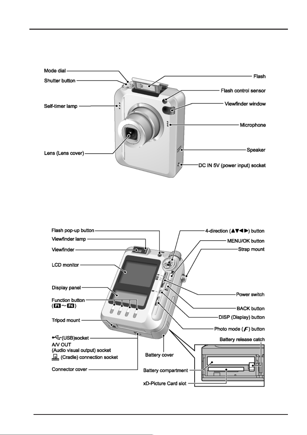
1-3. Names of External Components
1.General
7
2. Disassembly
2.Disassembly
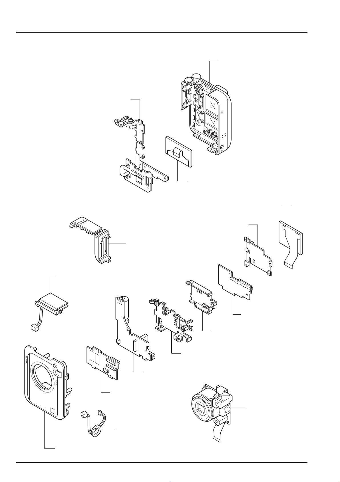
2-1. Names of internal Components
KEY PWB ASSY
FinePix F610 (US/EU/EG/GE/CA/AS) SERVICE MANUAL
R PANEL ASSY
B / W LCD
ST ASSY
LCD CONST
LCD FLAME
BATTERY LID ASSY
MAIN PWB ASSY
BATT FLAME
MAIN FLAME
DCST PWB UNIT
CAM PWB ASSY
LENS CONST
MIC SPEAKER ASSY
F PANEL ASSY
8
FinePix F610 (US/EU/EG/GE/CA/AS) SERVICE MANUAL
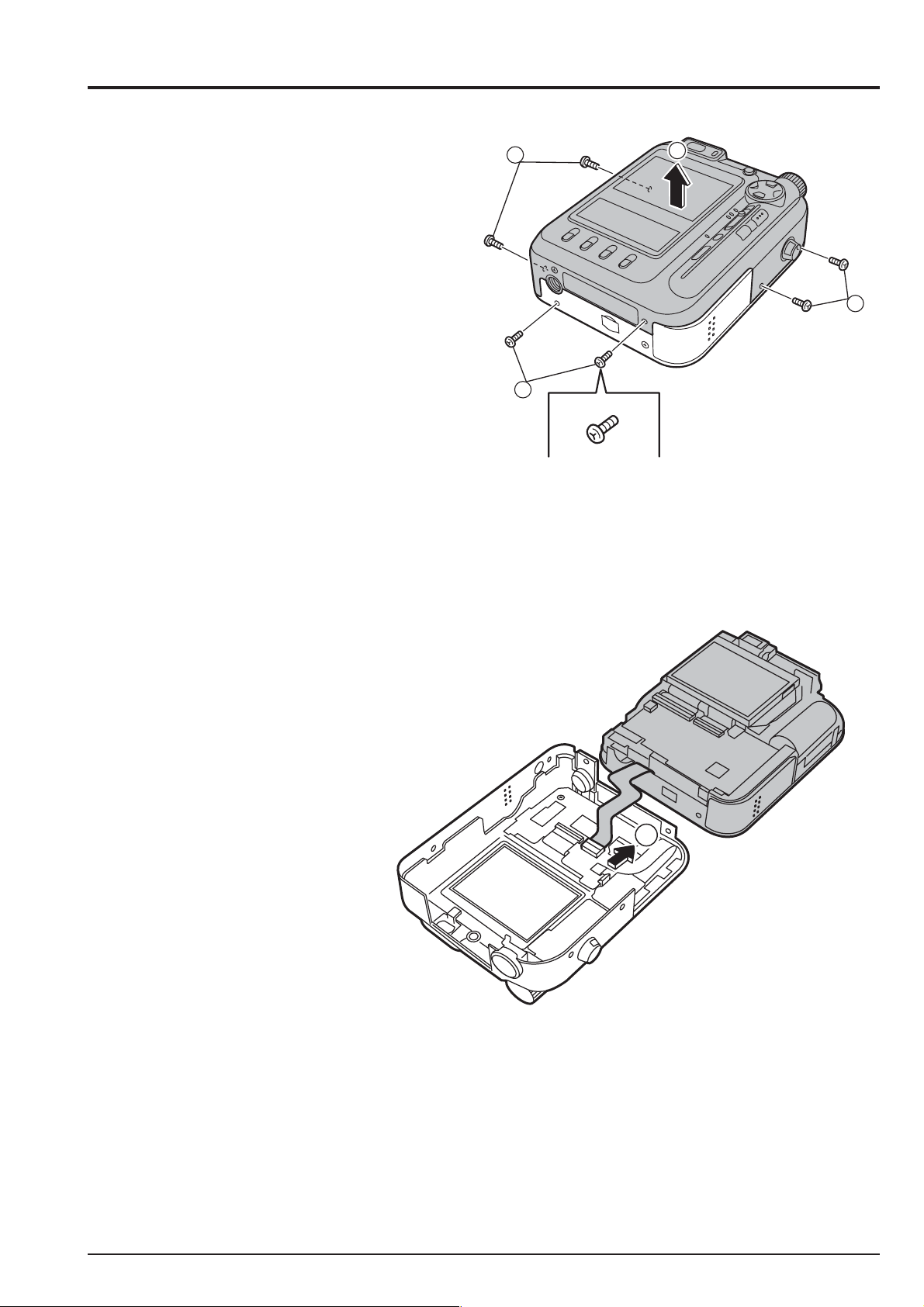
2-2. Removing R PANEL ASSY
* Remove in the order indicated by circled numbers.
< Step 1 >
(1) Remove six screws.
(** Remove it when there is a NP40-battery.)
(2) Remove R PANEL ASSY in the direction of the arrow.
2. Disassembly
1
1
Screw of special shape.
Use the driver of Jig number (ZJ00583-100).
2
1
< Step 2 >
(3) Release the lock of the connector, and remove
R PANEL ASSY.
[ Assembly ]
(1) Assemble it in the reverse order of disassembling.
(2) Tighten the screw so as not to make the space in
"R PANEL ASSY" and "F PANEL ASSY".
3
9
2. Disassembly
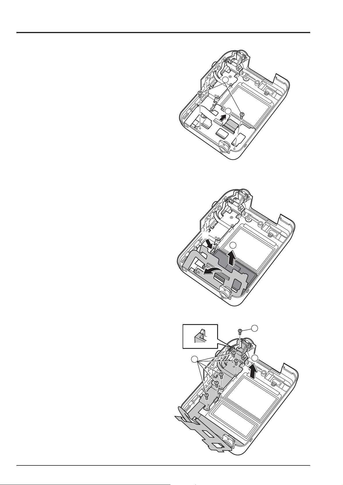
2-3. Removing B/W LCD and KEY PWB ASSY
* Remove in the order indicated by circled numbers.
< Step 1 >
(1) Remove two screws.
(2) Release the lock of the connector.
FinePix F610 (US/EU/EG/GE/CA/AS) SERVICE MANUAL
1
2
< Step 2 >
(3) Raise KEY PWB ASSY, and remove B/W LCD.
< Step 3 >
(4) Remove five screws.
(5) Remove the hook, and remove KEY PWB ASSY in the
direction of the arrow.
A
3
4
4
5
[ Assembly ]
(1) Assemble it in the reverse order of disassembling.
10
FinePix F610 (US/EU/EG/GE/CA/AS) SERVICE MANUAL
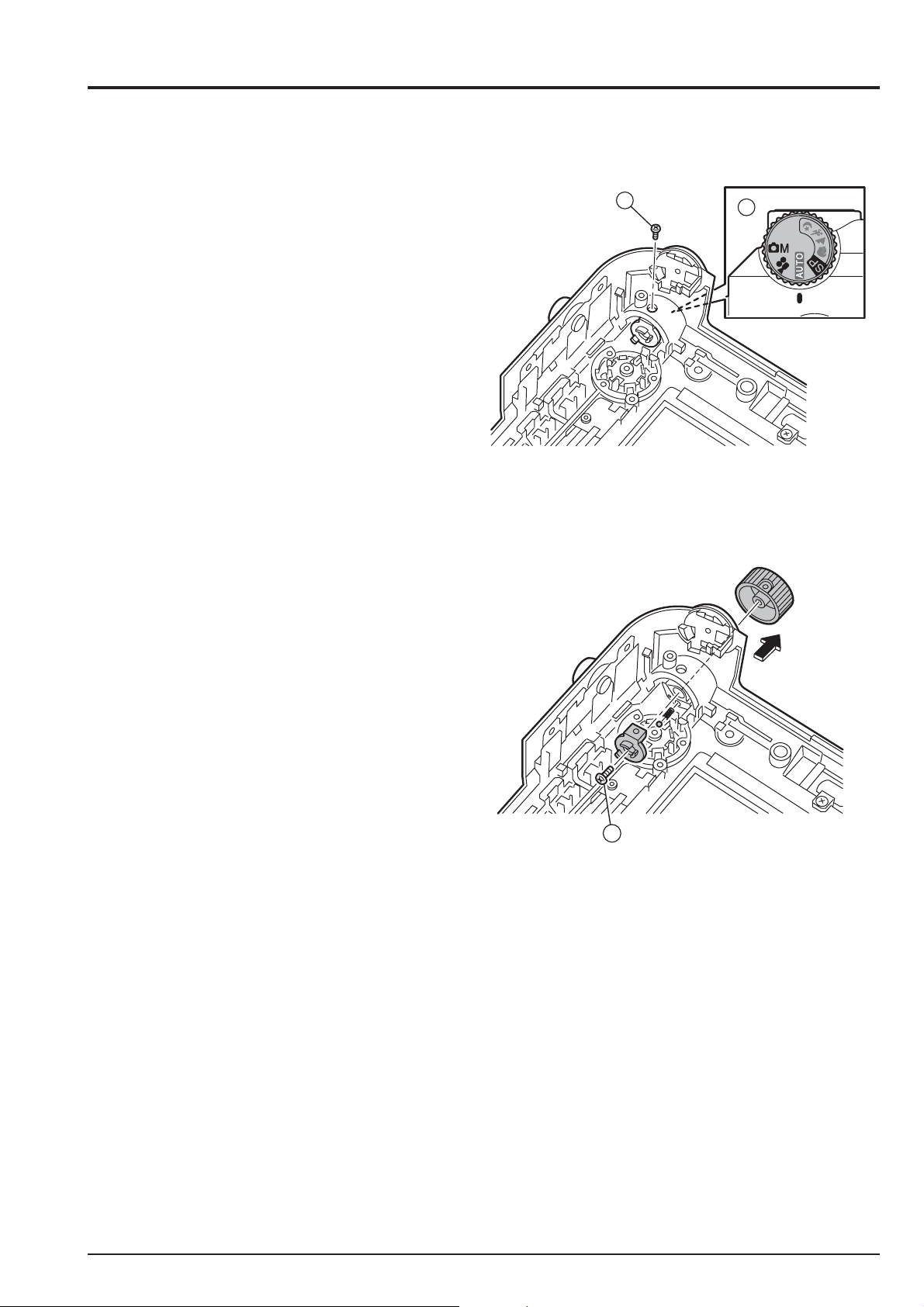
2-4. Removing MODE DIAL
* Remove in the order indicated by circled numbers.
< Step 1 >
(1) Change to the AUTO mode.
(2) Remove one screws.
2. Disassembly
2
1
< Step 2 >
(3) Remove one screw, and remove MODE DIAL in the
direction of the arrow.
3
Note the dropout and the loss of the click ball.
[ Assembly ]
(1) Assemble it in the reverse order of disassembling.
11
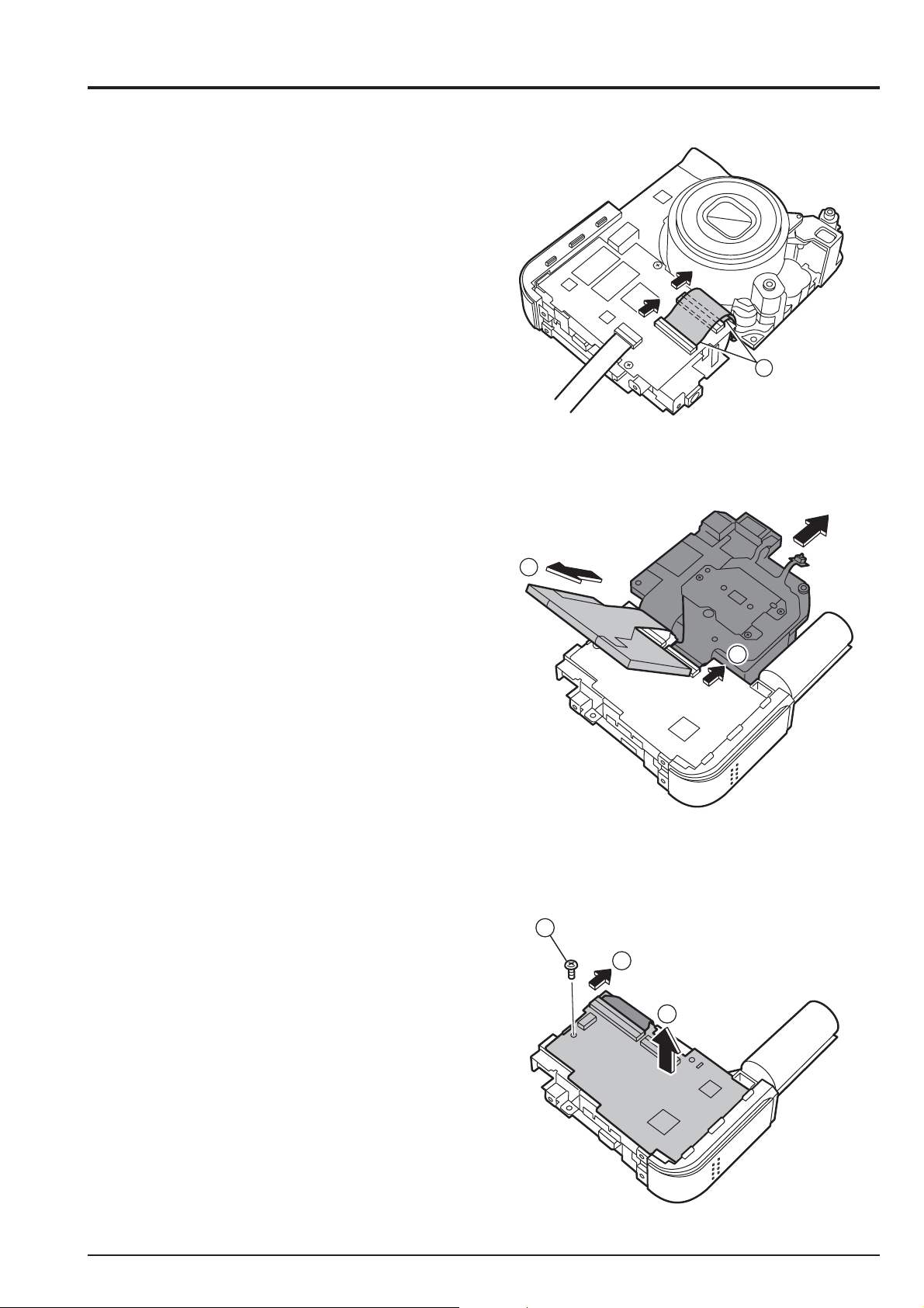
2. Disassembly
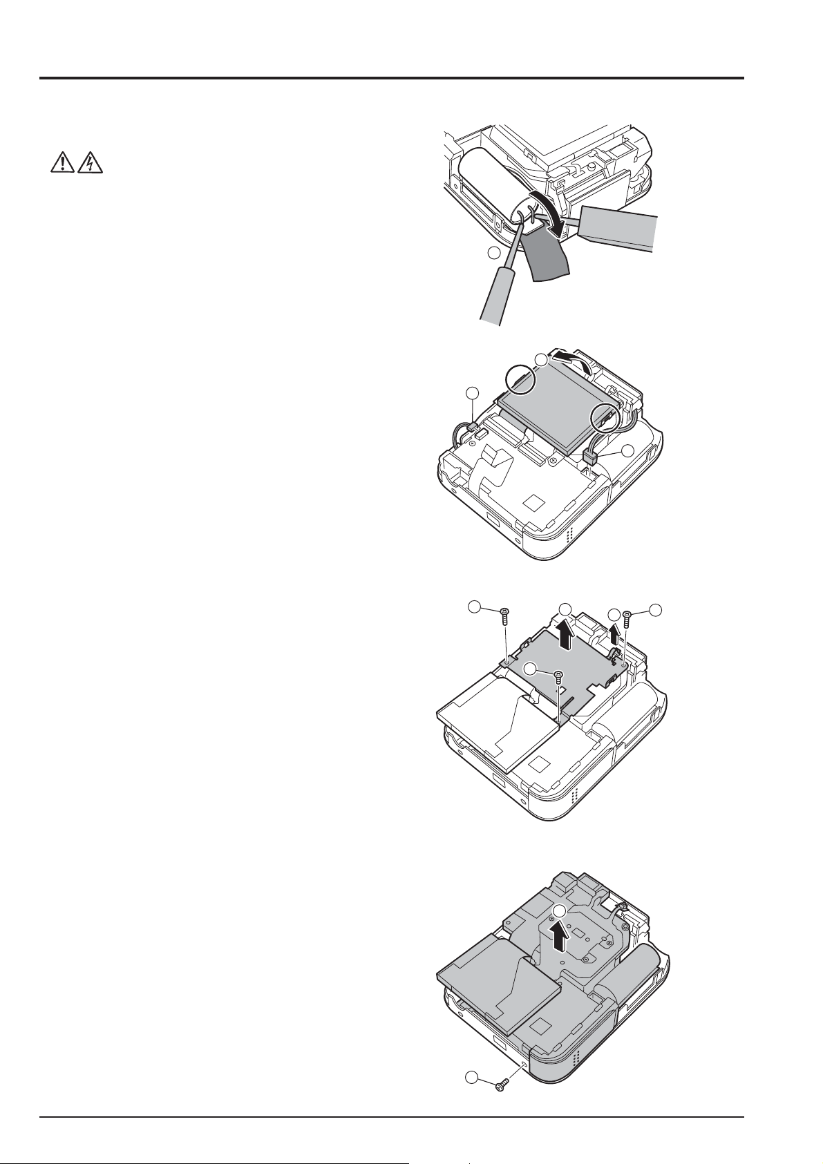
2-5. Removing DSC BLOCK
* Remove in the order indicated by circled numbers.
< Step 1 >
(1) Peel off the UL tape, and discharge the flash.
FinePix F610 (US/EU/EG/GE/CA/AS) SERVICE MANUAL
1
< Step 2 >
(2) Remove the connector two places.
(3) Remove the hook of LCD FRAME, and raise LCD.
< Step 3 >
(4) Remove three screws.
(5) Remove push switch from LENS CONST.
(6) Remove LCD PLATE in the direction of the arrow.
3
2
2
4
6
4
4
5
< Step 4 >
(7) Remove DSC BLOCK in the direction of the arrow.
[ Assembly ]
Assemble it in the reverse order of disassembling.
12
8
7
FinePix F610 (US/EU/EG/GE/CA/AS) SERVICE MANUAL
2-6. Removing LCD CONST and LENS CONST
* Remove in the order indicated by circled numbers.
< Step 1 >
(1) Remove the connector two places.
< Step 2 >
(2) Remove LCD CONST.
(3) Remove the lock of the connector, and remove LENS CONST.
2. Disassembly
1
2-7. Removing CAM PWB ASSY
* Remove in the order indicated by circled numbers.
< Step 1 >
(1) Remove onescrew.
(2) Remove the connector one places.
(3) Remove CAM PWB ASSY in the direction of the arrow.
2
3
1
2
3
13
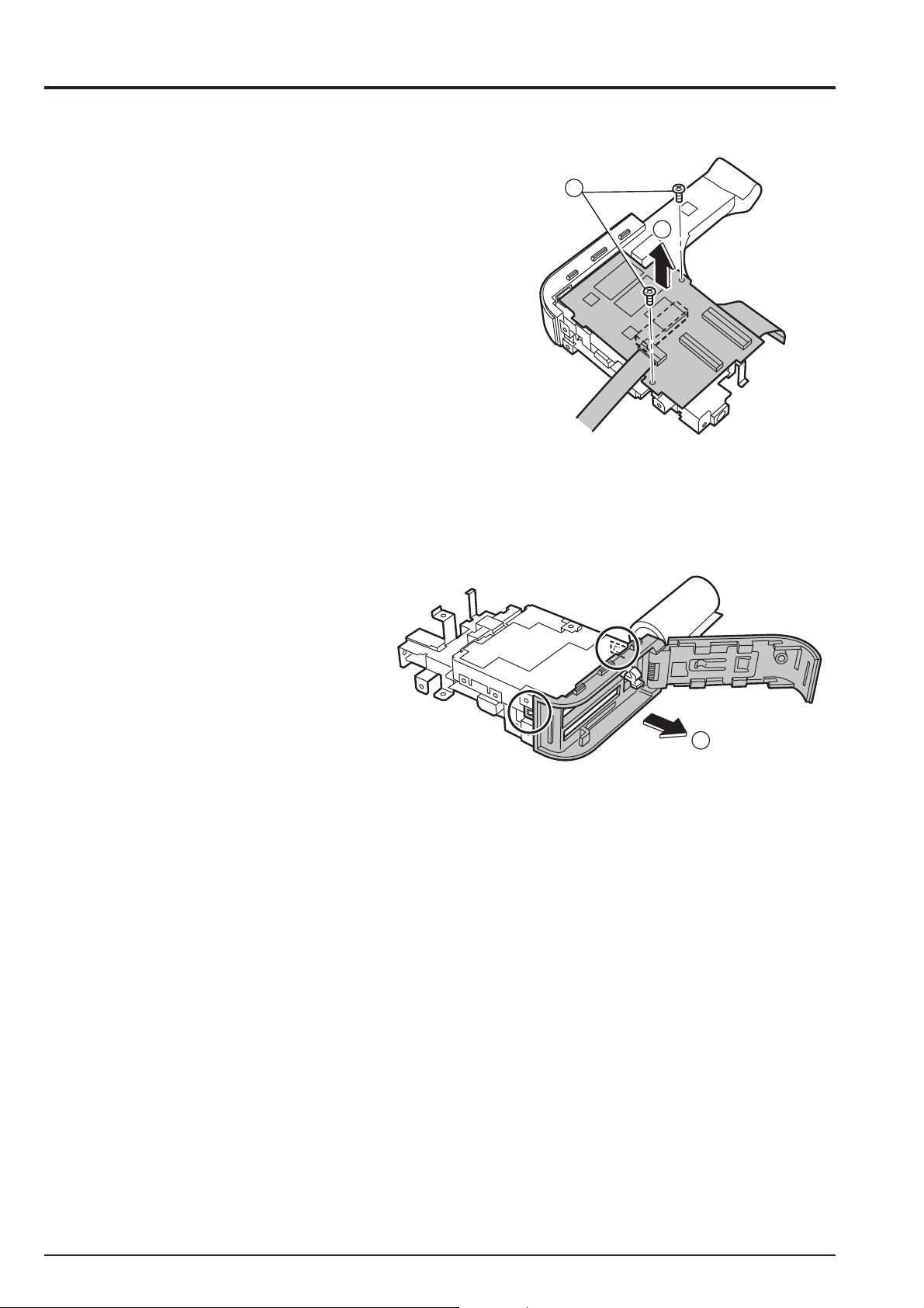
2. Disassembly
2-8. Removing MAIN PWB ASSY
* Remove in the order indicated by circled numbers.
< Step 1 >
(1) Remove two screw.
(2) Remove the connector of board to board, and remove
MAIN PWB ASSY in the direction of the arrow.
2-9. Removing BATTERY LID ASSY
* Remove in the order indicated by circled numbers.
< Step 1 >
(1) Remove the hook in two places, and remove
BATTERY LID ASSY in the direction of the arrow.
FinePix F610 (US/EU/EG/GE/CA/AS) SERVICE MANUAL
1
2
2-10. Removing DCST PWB CONST
* Remove in the order indicated by circled numbers.
< Step 1 >
(1) Remove two screw.
(2) Remove DC PWB CONST in the direction of the arrow.
1
14

FinePix F610 (US/EU/EG/GE/CA/AS) SERVICE MANUAL
3. Schematic
3. Schematic
3-1. Cautions
<Caution when replaceing chip (leadless) parts.>
* Do not re-use the removed parts, but use new parts.
Be careful that the negativ side of the tantalum capacitors are susceptible to heat.
* Voltage indications are omitted for capacitors other than chemical and tantalum capacitors
with a dielectric strength of 50 V or less.All units are uF (p shows pF).
* Chip resistors without indication are 1/10 W.
* k=1000
* Variable resistors and semi-variable resistor are abbreviated the specification of B characteristic.
3-2. Basic block name and function explanation
Board Name Block name Function
LENS ASSY CCD BLOCK * CCD output (IC1)
CAM PWB ASSY CAM BLOCK * Analog to digital conversion of CCD output (IC103)
MAIN PWB ASSY MOTOR BLOCK * Zoom/AF/shutter/iris drive (IC153)
DCST PWB UNIT DC/DC BLOCK * Each power supply generation (IC501 / IC511)
LCD CONST LCD BLOCK * LCD Panel
KEY PWB ASSY SW BLOCK * Operation SW ( F-Mode / +- AE / A-mode / S1->S2 / MODE /
, M=1000 k
* CCD driver (IC102)
AUDIO BLOCK * Audio signal processing (IC451)
PROCESS BLOCK * Video signal processing (IC204)
* USB communication (IC204)
* System control/SW detection management (IC204)
* Flash_ROM (IC205)
* SD-RAM (IC203, IC206)
POWER ON BLOCK * Power supply management (POWER_ON_IC351)
LCD BLOCK * LCD controller / B /W LCD controller
STRB BLOCK * Flash luminescence processing (IC752)
JACK BLOCK * Multiple connector
VIDEO BLOCK * VIDEO drive(IC301)
CHG BLOCK * Charge control (IC302)
F1 - F4 / U<->D / L<->R / OK<->CANCEL /
DISP TELE<->WIDE / MENU<->OK / POWER_ON)
15

3. Schematic
FinePix F610 (US/EU/EG/GE/CA/AS) SERVICE MANUAL
3-3.Functions of Primary Blocks
3-3-1.Technical Outline
Use of [the 4th Generation Super CCD Honeycomb HR] has improved still photography performance. The 6.3
million effective pixels, and [the Honeycomb Signal Processing System], allows recording and reproduction of highquality images of up to 4048 x 3040 (1.23 million) pixels. These features permit [Candle Shots] at ISO800 in the
1Mega mode, a capability facilitated by the use of the unique honeycomb picture element which receives light over a
wide area, technical developments in pixel summing signal processing*1, and noise reduction technology.
Movie photography performance is improved. Horizontal/vertical pixel mixing*2 inside the CCD using a new data
transfer system is the first to provide 30 frames per second in VGA format at greater than 3 megapixels.
*1 : Image data obtained with honeycomb signal processing from twice the number of effective pixels. Shrinks four
pixels into one. This processing increases the signal level (sensitivity) by a factor of four, and the S/N ratio (signal-to-
noise ratio) by a factor of two, to permit photography at ISO800.
*2 : Mixes two pixels on the vertical axis, and two pixels on the horizontal axis, of the CCD.
This processing increases the signal level by a factor of four, and the S/N ratio by a factor of two, to provide high
sensitivity and high quality images, while at the same time allowing data to be read at high-speed (30 frames per
second in VGA format).
3-3-2.CAM Board Block Functions
Photography Circuit Functions (CAM BLOCK)
The analog video signal output from the newly developed CCD (1/1.7”, 6.3 million effective pixels, square pixel
honeycomb array, primary color CCD) is processed (pseudo-color compensation, adaptive interpolation, amplification,
and signal mixing) in ACS_IC (IC102:CSP_IC), and subsequently converted to a 12-bit digital signal. The digital
signal is then sent to the single chip image signal processing LSI : UCS2_IC (IC204 : CSP_IC*).
* CSP_IC=
3-3-3.MAIN Board Block Functions
Image Signal Processing Functions (PROCESS BLOCK)
Data input from CCD
* The 12-bit digital image data (1H equivalent) output from the CAM BLOCK is sent to UCS2_IC, buffered in the IBUF,
and converted to 32-bit (16-bit x 2) data. The 32-bit image data is then sent from the [I/O Buffer] in UCS2_IC and
stored in the SDRAM_IC (IC203, IC206 : 40 Mbyte). A single frame (4080 pixels x 3040 lines) of image data is
temporarily stored in the SDRAM_IC.
* At the same time, AE multiplies the 12-bit image data input from the UCS2_IC in [AUTO], and sends the data required
for AE/AWB/AF to the SDRAM_IC. To provide the appropriate data for AE/AWB/AF, this data is then sent from the
SDRAM_IC in serial format to the ACS_IC via the UCS2_IC.
Recording in the xD media
The image data stored in the SDRAM_IC is converted from 32-bit to 12-bit data one line at a time in the [IBUF] in the
UCS2_IC, and sent to [YC PRO]. The image data is then converted to 8-bit Y and C signals in [YC PRO], and then sent
again to [IBUF]. The 8-bit Y and C signals are then converted to 8-bit Y, Y, Cb, and Cr signals and sent to the
SDRAM_IC. The image data stored in the SDRAM_IC is compressed with [JPEG] in the UCS2_IC and again stored in
the SDRAM_IC. The image data following compression is recorded sequentially in the xD media in the UCS2_IC.
Image Replay from the xD media
The compressed image data from the xD media is sent to UCS2_IC, and stored in the SDRAM_IC via [MEDIA]. The
compressed image data stored in the SDRAM_IC is expanded with JPEG and stored again in the SDRAM_IC. The
expanded image data is sent to [YC PRO] via [IBUF]. Gain control for the luminance and color difference signals, and
aperture processing, are performed in [YC PRO] and the image data then sent again to the SDRAM_IC. The image
data is then displayed via [ENCD] and [D/A].
Movie Mode
The 12 bit digital image data output from the (CAM BLOCK) is converted to 8-bit Y and C signals in the USC2_IC [YC
PRO], and sent to the SDRAM_IC. The image data stored in the SDRAM_IC is compressed with [JPEG] in the
UCS2_IC and again stored in the SDRAM_IC. The image data following compression is recorded sequentially in the
SSFDC via [MEDIA] in the UCS2_IC.
The photography adjustment data is stored in the FLASH_ROM (In the IC205). The FLASH_ROM also incorporates
firmware.
LCD Control Functions (LCD CONTROL BLOCK)
The R, G, and B signals processed in the image signal processing UCS2_IC are output to the LCD panel via [LCD CONT].
A low-temperature polysilicon TFT color LCD monitor (1.8, 134,000 pixels) is used.
Chip Size Packege IC
3-3-4.DCST Board Block Functions
Power Supply Functions
The power supply circuit on the DCST board generates the -8V/-11V/16V (CCD), 1.5V (UCS2_IC), 3.3V
(ACS_IC/UCS2_IC/SDRAM/SDRAM/ROM/LED/KEY), MOT_5.0V (lens/flash), D_5V (AUDO), LCD_13V (LCD
backlight), D_3.3V (LCD circuit), and AD_3.3V (video circuit) voltages.
16
FinePix F610 (US/EU/EG/GE/CA/AS) SERVICE MANUAL
)
)
)
)
(
)
A
A
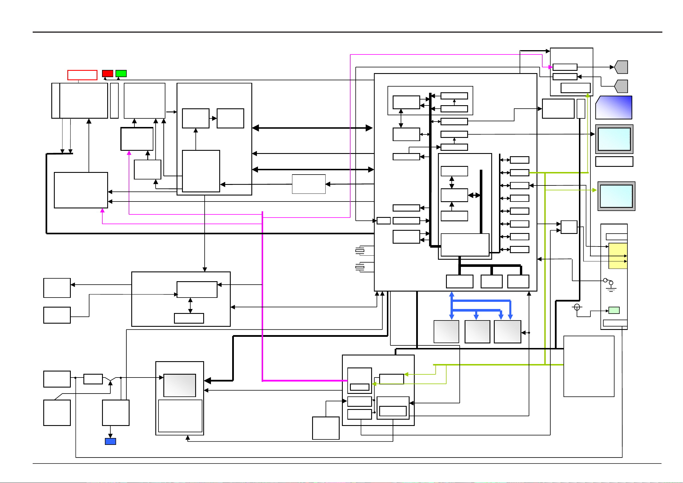
3. Schematic
3-4.BLOCK Diagram
3xZOOM LENZ
IRIS 10Steps
WIDE/TELE
Variable
LENS BARRIER
Zoom position
Zoom HP
STRB-XE
P-TR
DC IN
5V
NP-40
BATT.
FINDER
Focus HP
Motor Drv.
M50233HP
6ch
Detect sy
stem
FUSE
SELF TIMER & Batt CHG
LED
LED
WHA-CCD
MS3891
1/1.7inch
6.3millon pixels
O.LPS
Cont.
Pulses
OFD/RG
BIAS
SHT PULSE
Focus,Iris,Zoom Pulse
OFD_CONT
VI_CONT,VF_CONT,VZ_CONT
Charge IC
M62246
LED
V
V Drv.
MD2174
CCDIN
Analog
Block
H
TG
(Programble)
V Pulses
STRB BLOCK
STRB IC
FF1160
STRB C
DC/DC Block
DC/DC IC.
AN3021xA
5ch
1.5V
2.5V
3.3V
5V
CCD16V, -8V, -9V
ACS
AD80057
3.3V Operation
Analog
Bl
ock
STRB_SY
G_NO,G_SEL,
STRB_CHG
PWCTL
CCD[13-0]
VRESET,OCONT
VI,HI,ADCK,STB,LD,,DI,CLK,WAIT
CCDCLK
X’tal(36MHz)
STRB CONT
STRB_DIS,STRB_FULL,STRB_COK
DC/CD CONT
CCD_ON,
BL_ON,PANEL_ON,
BATT
Ba
ckup
X’TAL
CX-53F
48.00MHz
X’TAL
CX-53F
27..00MHz
,STRB_CC
DP_DET
EVR
8ch
RTC
PIO
A/D
PWON IC
FF1139
CTL
Power on
Reset
IBFC
RECC RECC
YCPRO YCPRO
CGENCGEN
Audio(Seriul
Audio(Seriul
Audio(A/D
Audio(A/D
JPEG JPEG
UCS2
SIO_1
(U2_SIO)
SIO_2
(EVR_SIO)
_ACT
PWON
RESET
LIBRA 3.3V Operation
AUTOAUTO
CCDIFCCDIF
MEDIAMEDIA
TFDCTFDC
ENCDENCD
TX49 CPU Core TX49 CPU Core
DEBUG I/FDEBUG I/F
CPU CoreCPU Core
I-cache 16kI-cache 16k
Peripheral BUS 96MHz Peripheral BUS 96MHz
BUS Cont.
BUS Cont.
SDRAMC
SDRAMC
DMAC
DMAC
Internal
I/O Buffer I/O Buffer
SDRAM
256Mb x16
VIDE
Internal
eDRAMA
eDRAMA
DDRESS BUS [21
DATA BUS
SDRAM
256Mb x16
O_ON
[0-31]
Internal
Internal
eDRAMB
eDRAMB
FLASH
4MB
WDT
SIO SIO
USB
MFT MFT
ICU ICU
ADC ADC
PORT PORT
CLKC CLKC
xD Card
Slot
20PIN
VBS_OUT
AUDIO IC
BH6415KN
SP_AMP
MIC_AMP
CTL
Video
Driver
CRD_DET
D_3.3V
MODE DIAL
CAM/PB SW
POWER SW
R/L/D/U SW
OK/BACK/DISP/
FMODE SW
FUNCTION SW
RELEASE SW(S1/S2)
xD PictureCard
DR_SW
LCD Panel
BL LED x3
SIO_1(U2_SIO)
UDIO OUT
KEY
SPEAKER
MIC
1.8inch
B/W LCD
Panel
Cradle
USB I/F
14p
MULTI
LED
DC IN 5V
17
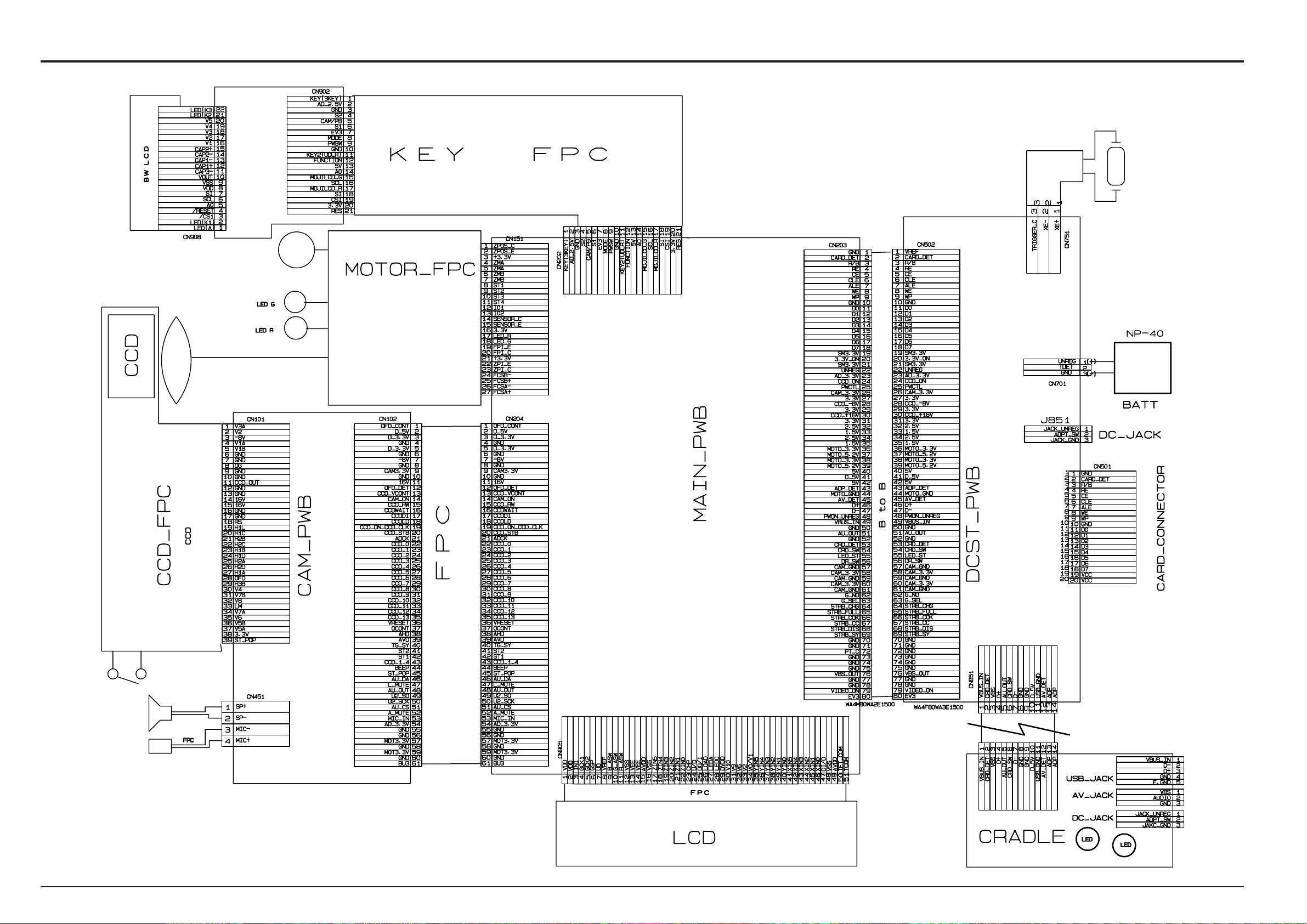
3. Schematic
3-5.Overall Connections
FinePix F610 (US/EU/EG/GE/CA/AS) SERVICE MANUAL
Xe
LENS
18
SP
MIC
FinePix F610 (US/EU/EG/GE/CA/AS) SERVICE MANUAL
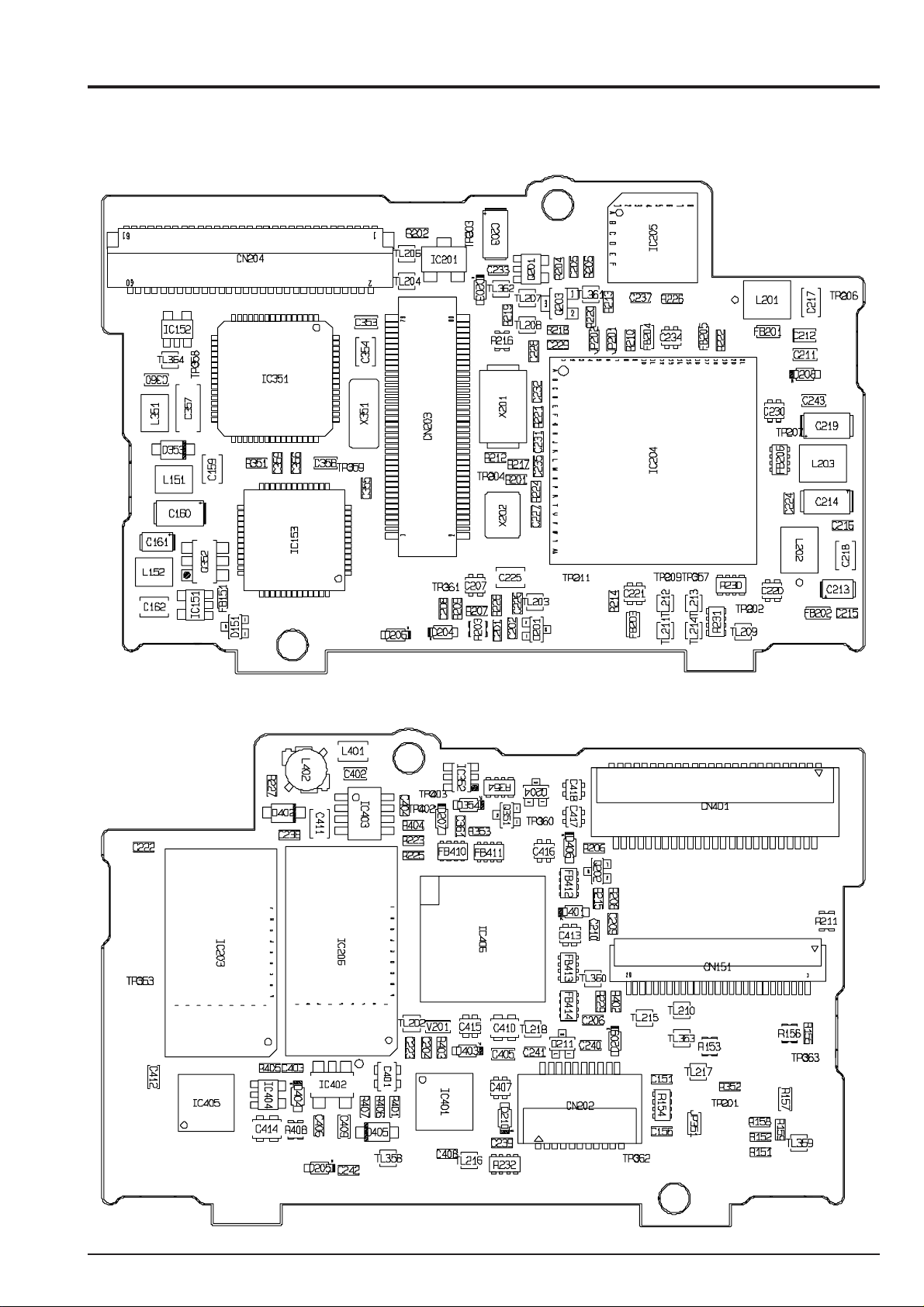
3-6. Board mounting diagram
3-6-1. Printed wiring board of MAIN PWB ASSY
< A side >
3. Schematic
< B side >
19
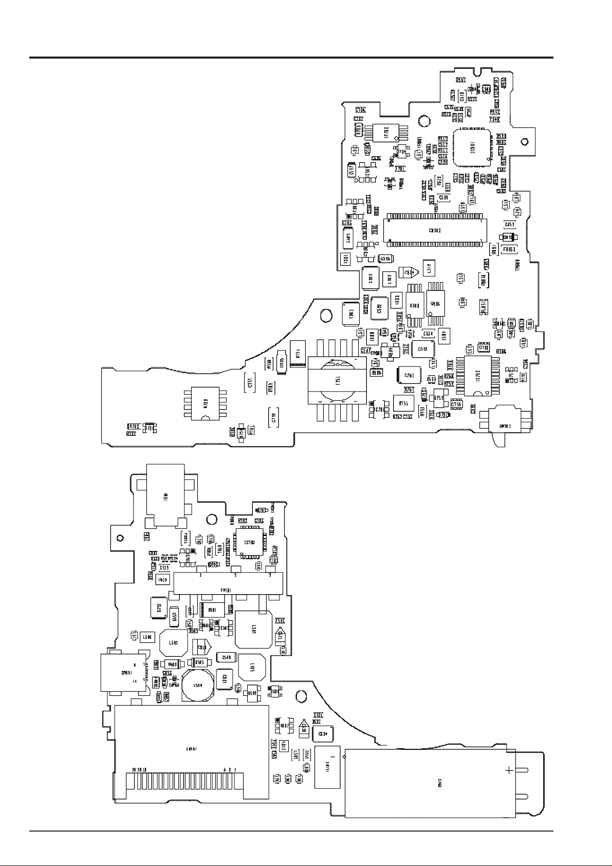
3. Schematic
3-6-2. Printed wiring board of DCST PWB CONST
< A side >
FinePix F610 (US/EU/EG/GE/CA/AS) SERVICE MANUAL
< B side >
20
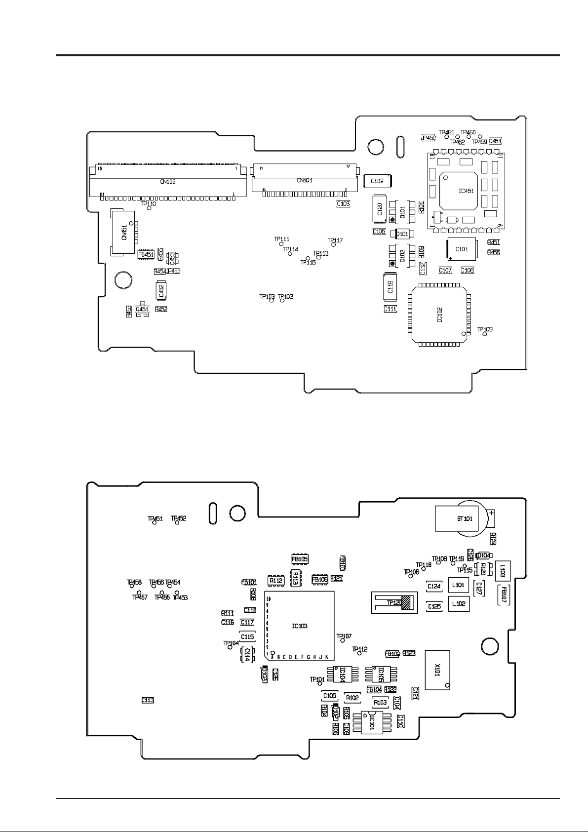
FinePix F610 (US/EU/EG/GE/CA/AS) SERVICE MANUAL
3-6-3. Printed wiring board of CAM PWB ASSY
< A side >
3. Schematic
< B side >
21

3. Schematic
3-6-4. Printed wiring board of CCD PWB ASSY
< A side >
FinePix F610 (US/EU/EG/GE/CA/AS) SERVICE MANUAL
< B side >
22
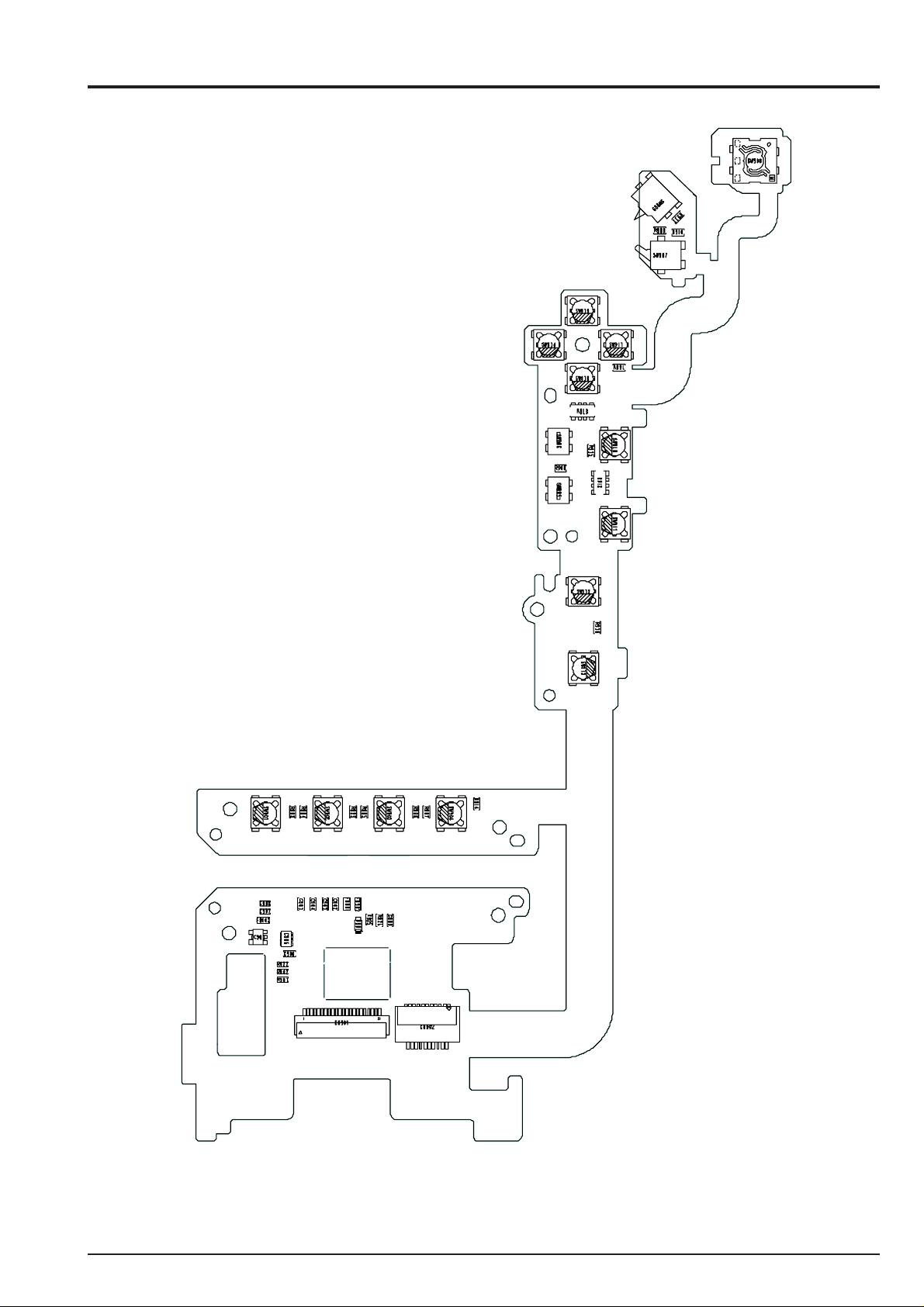
FinePix F610 (US/EU/EG/GE/CA/AS) SERVICE MANUAL
3-6-5. Printed wiring board of KEY FPC PWB ASSY
3. Schematic
23
3. Schematic
3-7.Circuit diagram
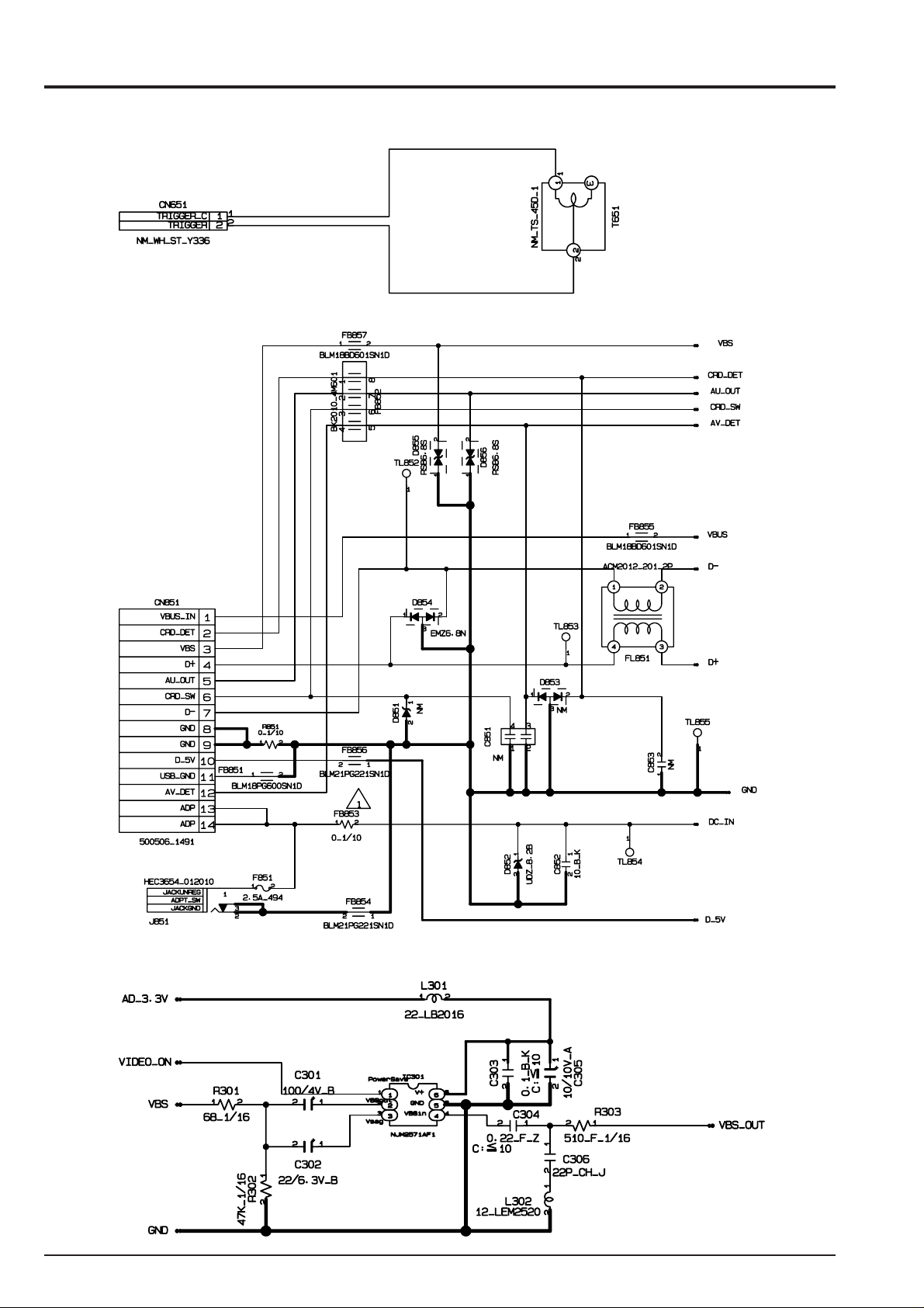
3-7-1. XE BLOCK Circuit
3-7-2. JACK BLOCK Circuit
FinePix F610 (US/EU/EG/GE/CA/AS) SERVICE MANUAL
3-7-3. VIDEO BLOCK Circuit
24
FinePix F610 (US/EU/EG/GE/CA/AS) SERVICE MANUAL
3. Schematic
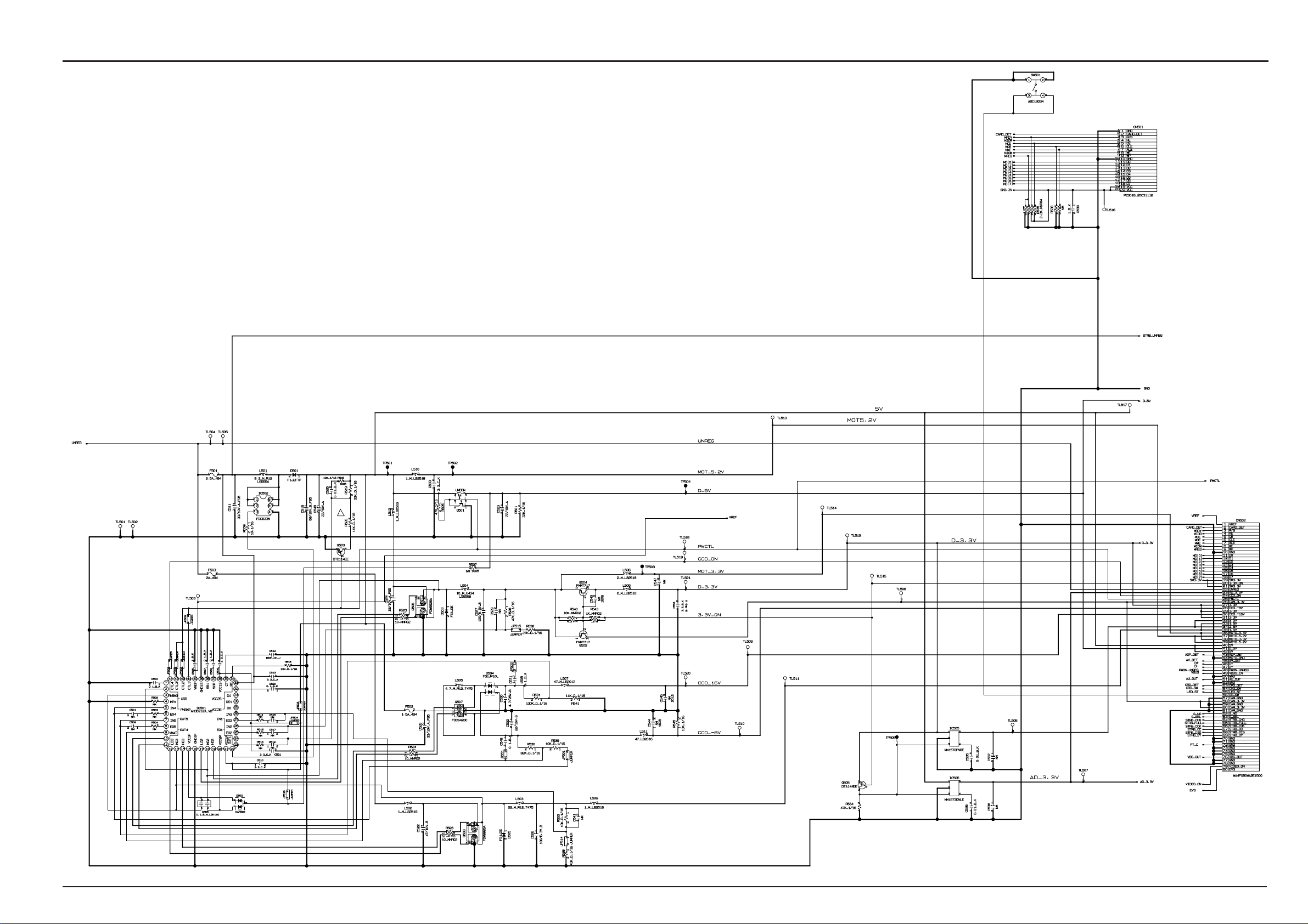
3-7-4.DC/DC BLOCK Circuit
25

3. Schematic
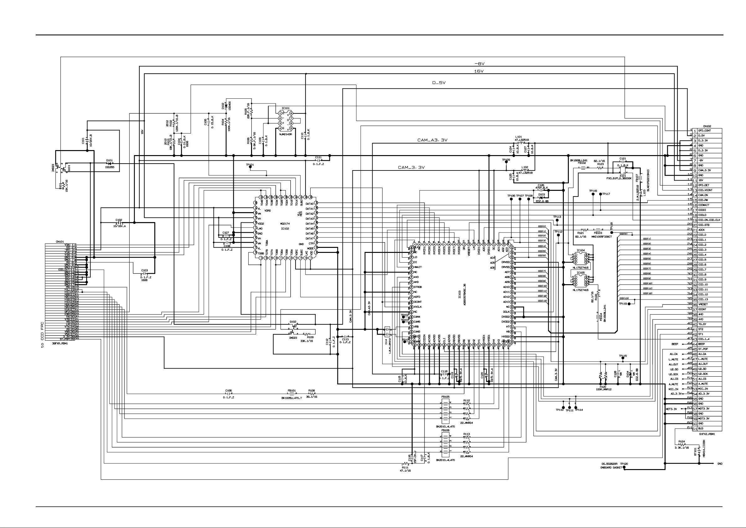
3-7-5.PROCESS BLOCK Circuit
FinePix F610 (US/EU/EG/GE/CA/AS) SERVICE MANUAL
26
FinePix F610 (US/EU/EG/GE/CA/AS) SERVICE MANUAL
3. Schematic
3-7-6.CAM BLOCK Circuit
27
 Loading...