

FUJIFILM FinePix F402 Service Manual

DIGITA L CAMERA
FinePix F402
SER VICE MANUAL
U/E/EG-Model
W ARNING
THE COMPORNENTS IDENTIFIED BY THE MARK “ ” ON THE SCHEMA THIC
DIAGRAM AND IN THE PARTS LIST ARE CRITICAL FOR SAFETY.
PLEASE REPLACE ONLY B Y THE COMPONENTS SPECIFIED ON THE SCHEMATHIC
DIAGRAM AND IN THE PART S LIST.
IF YOU USE WITH PA RT NUMBER UN-SPECIFIED, IT MAY RESULT IN A FIRE AND A N
ELECTORICAL SHOCK.
Ref.No.:ZM00462-103
FUJI PHOTO FILM CO.,LTD.
Printed in Japan 2002.09(S.K.)

SAFETY CHECK-OUT
After correcting the original problem, perform the following
safety check before return the product to the costomer.
FinePix F402 SERVICE MANUAL
1. Check the area of your repair for unsoldered or
poorly soldered connections. Check the entire
board surface for solder splasher and bridges.
2. Check the interboard wiring to ensure that no
wires are “pinched” or contact high-wattage
resistors.
3. Look for unauthorized replacement parts, particularly transistors, that were installed during a
previous repair. Point them out to the customer
and recommend their replacement.
4. Look for parts which, though functioning, show
obvious signs of deterioration. Point them out to
the customer and recommend their replacement.
5. Caution:
For continued protection against
2.5A 125/250V
2.5A 125/250V
RISK OF FIREREPLACE FUSE
AS MARKED
fire hazard, replace only with same
type 2.5 amperes 125/250 volts
fuse.
Attention:
Afin d’assurer une protection
permanente contre les risques
d’incendie, remplacer uniquement
par un fusible de meme, type 2.5
amperes, 125/250 volts.
6. Warning:
To reduce the electric shock, be
WARNING!
HIGH VOLTAGE
careful to touch the parts.
2

FinePix F402 SERVICE MANUAL
1. General
1-1.Product specification .................................................................................................................................................... 4
1-2.Names of External Components .................................................................................................................................. 7
1-3.Names of Internal Components.................................................................................................................................... 8
2. Disassembly
2-1.Removing the CABI R Assembly .................................................................................................................................. 9
2-2.Removing the CABI F Assembly ................................................................................................................................10
2-3.Removing the CABI Bottom Assembly ...................................................................................................................... 10
2-4.Removing the Flash PWD ............................................................................................................................................ 11
2-5.Removing the LCD Unit ................................................................................................................................................ 11
2-6.Removing the Lens CONST ........................................................................................................................................ 12
2-7.Removing the CAM PWB Assembly........................................................................................................................... 12
2-8.Removing the Main PWB Assembly........................................................................................................................... 13
2-9.Removing the Audio PWB Assembly......................................................................................................................... 13
3. Schematics
3-1.Cautions ........................................................................................................................................................................ 14
3-2.Basic Block Names and Functions ............................................................................................................................ 14
3-3.Functions of Primary Blocks ...................................................................................................................................... 15
3-4.Block Diagram............................................................................................................................................................... 17
3-5.Overall............................................................................................................................................................................ 18
3-6.Mounting Diagram............. ............................................................................................................................................ 19
TABLE OF CONTENTS
TABLE OF CONTENTS
Page
4. Adjustments
4-1. Adjustment Items and Procedures when Replacing Primary Parts ................................................................... 21
4-2.Measuring Devices ...................................................................................................................................................... 21
4-3.Jigs ................................................................................................................................................................................. 21
4-4.Jig Connections ............................................................................................................................................................ 22
4-5.Environment Setup ....................................................................................................................................................... 22
4-6.Installing the Jig Drivers on the PC............................................................................................................................ 23
4-7.Installing and Starting the Adjustment Software .................................................................................................... 24
4-8.Initializing the Adjustment Software ......................................................................................................................... 24
4-9.Starting the Adjustment software ............................................................................................................................. 27
4-10.CCD data input............................................................................................................................................................ 29
4-11.Camera adjustment .................................................................................................................................................... 31
4-12.AF adjustment ............................................................................................................................................................. 33
4-13.Battery voltage adjustment ....................................................................................................................................... 34
4-14.Flash adjustment ........................................................................................................................................................ 36
4-15.Firmware Download .................................................................................................................................................. 37
4-16.End Setting .................................................................................................................................................................. 39
5. Inspection
5..Inspection ........................................................................................................................................................................ 42
6. Parts List
6-1.Packing and Accessories ........................................................................................................................................... 45
6-1-1.U Model .................................................................................................................................................................. 45
6-1-2.E Model .................................................................................................................................................................. 46
6-1-3.EG Model ................................................................................................................................................................ 47
6-2.Mechanical Parts.......................................................................................................................................................... 48
6-3.Electrical Parts .............................................................................................................................................................. 49
7. Appendix
7-1.List of Related Technical Updates Issued ........................................................................................... 50
3

1.General
y
e
)
)
)
)
9
98
97
B
B
B
B
0
69
0
s
8404802040160
0
3M
4
9
e
0
3
7
e
59
9
B
60012001280
FinePix F402 SERVICE MANUAL
1.General
1-1. Product specification
System
Model Digital camera FinePix F402
Number of effective pixel
CCD sensor 1/2.7-inch Super CCD in an interwoven pattern
Number of recorded pixels
File format Still image: JPEG (Exif ver. 2.2)
Storage media xD-Picture Card (16MB to 128MB)
Viewfinder Real image optical Approx. 83% coverage
Lens Fujinon optical fixed-focus lens
Aperture F3.2/F8 (automatically selected)
Focus TTL contrast-type, Auto focus
Focus distance f = 6.0 mm (Equivalent to 39 mm on a 35 mm camera)
Exposure control TTL 64-zones metering, Program AE, exposure compensation available in Manual
Sensitivity Equivalent to ISO 200/400/800/1600
White balance Auto (In Manual modes, 7 positions can be selected.)
Focal range Normal: Approx. 50 cm (1.6 ft.) to infinity
Shutter Variable-speed, 1/2 sec. to 1/2000 sec. (depend on Exposure mode)
Flash Auto flash using flash control sensor
Erase modes ERASE FRAME, ERASE ALL FRAMES, FORMAT (initialize)
LCD monitor 1.5-inches, low-temperature polysilicon TFT 117,000 pixels Approx. 96% coverage
Self-Timer 10 sec. timer clock
2.1million pixels
Number of total pixels 2.11 million pixels
2304 × 1728 pixels (4.0 million pixels)/1600 × 1200 pixels/ 1280 × 960 pixels/640 ×
480 pixels
* Design rule for Camera File System compliant, DPOF compatible
Movie: AVI format, Motion JPEG
photography mode
(ISO 800 and 1600 can only be set with in 1 mode.)
Macro: Approx. 6 cm (0.2 ft.) to 65 cm (2.1 ft.)
Effective range: Approx. 0.3 m-3 m
Flash modes: Auto, Red-Eye Reduction, Forced Flash, Suppressed Flash, Slow
Synchro
Qualit
No. of recorded pixel
Image Data Siz
PC-16 (16MB
PC-32 (32MB
PC-64 (64MB
PC-128 (128MB
Approx.
2304 172
1.6M
4
Approx.
1
Approx.
K
K
2
1
1
1
Approx.
1
20K
4
1
Input/Output Terminals
DC Input To connect the AC power Adapter AC-5VS/AC-5VHS
(USB) socket For file transfer to a computer and connection to the optional cradle
4
Approx.
12
2
4
.
130K
Movi
Approx.
Approx.
rox.
12.
Movi
12
Approx.
.
Approx.
.
Approx.
20.
40.

FinePix F402 SERVICE MANUAL
e
s
0
ON
0
0
F
y
t
f
g
t
t
g
g
f
s
s
r
n
r
e
)
n
n
n
y
g
n
er
y
a
r
y
1.General
Power Supply and Others
Power supply Use one of the following
Rechargeable Battery NP-40 or AC Power Adapter AC-5VS/AC-5VHS
Available shots using
the battery
(When fully charged)
-4
The number of shots shown here is an approximate guide to the number of consecutive shots that can be taken based on 50% flash usage at normal temperatures. However, the actual number of available shots will vary depending on the
ambient temperature when the camera is used and the amount of charge in the
battery. The number of available shots will be lower in cold conditions.
Conditions for use Temperature: 0
80% humidity or less (no condensation)
Camera dimensions 77 mm × 69 mm × 22 mm/3.0 in. × 2.7 in. × 0.9 in.
(W/H/D) (not including accessories and attachments)
Camera mass (weight)
Weight for photography
Approx. 125 g/4.4 oz. (not including accessories, batteries or xD-Picture Card)
Approx. 145 g/5.1 oz. (including battery and xD-Picture Card)
Accessories ! 16MB, xD-Picture Card (1) Supplied with: Anti-static case (1)
! Strap (1)
! USB Interface Set (1)
! NP-40 Rechargeable Battery (1) Soft case included
! AC-5VS/AC-5VHS AC Power Adapter (1) Approx. 2 m (6.6 ft.) connection cord
! Owner’s Manual (1)
Optional Accessories ! xD-Picture Card
! BC-65 Battery Charger ! NP-40 Rechargeable Battery
! AC-5VH/AC-5VHS AC Power Adapter
! PictureCradle CP-FX402 ! SC-FX402
! DPC-R1 Image Memory Card Reader
• Compatible with Windows 98/98 SE, Windows Me, Windows 2000 Profes-
• Compatible with xD-Picture Card of 16MB to 128MB, and SmartMedia of
! DPC-AD PC Card Adapter
• Compatible with xD-Picture Card of 16MB to 128MB, and SmartMedia of
attery Typ
LCD monitor
LCD monitor OF
o
C to +40oC (+32oF to +104oF)
No. of Shot
Approx. 14
Approx. 40
CD-ROM: Software for FinePix SX (1)
FinePix F402 Special USB cable with Noise Suppression core (1)
DPC-16 (16MB)/DPC-32 (32MB)/DPC-64 (64MB)/DPC-128 (128MB)
sional, Windows XP or iMac, Mac OS 8.6 to 9.2, Mac OS X (10.1.2 to
10.1.5) and models that support USB as standard.
3.3V, 4MB to 128MB.
3.3V, 2MB to 128MB.
elf timer lamp displa
Camera operatio
uring batter
chargin
witched o
lf-tim
photograph
onnected to
compute
ispla
Li
f
rinkin
Li
Li
rinkin
rinkin
f
Charging in progres
Charging complet
Charging erro
POWER switch set to ON (goes off after several seconds
From 10 seconds to 5 seconds before the shot is take
For 5 seconds or less before the shot is take
uring communication with a compute
Ready for disconnectio
tatu
5

1.General
FinePix F402 SERVICE MANUAL
Explanation of Terms
DPOF: Digital Print Order Format
DPOF is a format used for recording information on a storage media (image
memory card, etc.) that allows you to specify which of the frames shot using a
digital camera are printed and how many prints are made of each image.
EV: A number that denotes exposure. The EV is determined by the brightness of the
subject and sensitivity (speed) of the film or CCD. The number is larger for bright
subjects and smaller for dark subjects. As the brightness of the subject changes, a
digital camera maintains the amount of light hitting the CCD at a constant level by
adjusting the aperture and shutter speed. When the amount of light striking the
CCD doubles, the EV increases by 1. Likewise, when the light is halved, the EV
decreases by 1.
Frame rate (fps): The frame rate is a unit used to indicate the number of images (frames) played
back per second. This camera shoots movie files at 10 consecutive frames per
second, a rate that is expressed as 10 fps. By comparison, TV images are played
at 30 fps.
JPEG: Joint Photographics Experts Group
A file format used for compressing and saving color images. The compression
ratio can be selected, but the higher the compression ratio, the poorer the quality
of the expanded image.
Motion JPEG: A type of AVI (Audio Video Interleave) file format that handles images and sound
as a single file. Images in the file are recorded in JPEG format. Motion JPEG can
be played back by QuickTime 3.0 or later.
PC Card: A generic term for cards that meet the PC Card Standard.
PC Card Standard: A standard for PC cards determined by the PCMCIA.
PCMCIA: Personal Computer Memory Card International Association (US).
White Balance: Whatever the kind of the light, the human eye adapts to it so that a white object still
looks white. On the other hand, devices such as digital cameras see a white sub-
ject as white by first adjusting the color balance to suit the color of the ambient
light around the subject. This adjustment is called matching the white balance. A
function that automatically matches the white balance is called an Automatic
White Balance function.
6

FinePix F402 SERVICE MANUAL
r
r
/
1-2.Names of External Components
1.General
Shutter button
Flash
Microphone
Self-timer lamp
POWER switch
Viewfinder window
Flash control senso
Lens/Lens cove
(USB) socket
Cradle connection
socket
DC IN 5V (Power input) socket
Mode switch
Viewfinder
Viewfinder lamp
DISP button
LCD monitor
Battery cover
/Macro button
( ) ( )
Zoom button
/Flash button
MENU/OK button
BACK button
Strap mount
Battery compartment
Battery release catch
xD-Picture Card slot
7

1.General
1-3.Names of Internal Components
KEY FPC ASSY
FinePix F402 SERVICE MANUAL
R PANEL ASSY
MIC ASSY
CAM PWB ASSY
LCD ASSY
STROBO ASSY
BATT HOLDER ASSY
LENS CONST
AUDIO PWB ASSY
MAIN PWB ASSY
F PANEL ASSY
CABI BOTTOM ASSY
8

FinePix F402 SERVICE MANUAL
2. Disassembly
2-1. Removing the CABI R Assembly
1
3
2. Disassembly
1 Remove the five screws.
2 Open the battery cover in the direction of the arrow.
3 Place the finger on the battery cover and remove the
CABI R assembly in the direction of the arrow.
* The screw holding the CAB F on the base need not
be removed.
1
2
1
<Removing screws in the cover>
* The five F402 CABI R (one CAB F) screws are
of a special shape, and require a special
screwdriver for removal.
The special screwdriver is available as a jig.
(Special screwdriver: ZJ00583-100)
4 Remove the flexible cable from the connector.
4
<Assembly>
* Indicates the position of the CABI F side switch dur-
ing assembly.
Power switch: Closed
Lens barrier: Closed
<Discharge location>
Contact the discharger to the condenser lead to
discharge.
<Assembly>
* Assemble so that the frame is on the inner CAB
side.
9
2. Disassembly
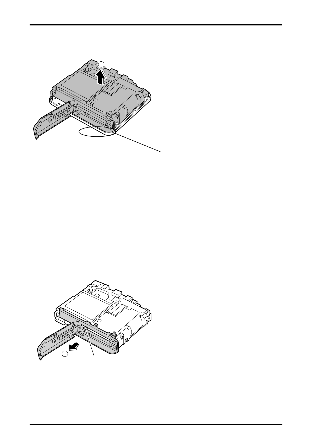
2-2. Removing the CABI F Assembly
FinePix F402 SERVICE MANUAL
1
1 Lift the entire unit in the direction of the arrow and
remove from the CABI F.
<Assembly>
* Fit the CABI F tightly to ensure that there are no
gaps in the CABI bottom.
2-3. Removing the CABI Bottom Assembly
1
Tab
1 Remove in the direction of the arrow while releas-
ing the tab on the bottom assembly.
10

FinePix F402 SERVICE MANUAL
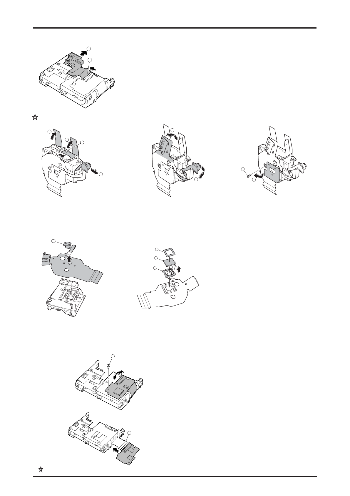
2-4. Removing the Flash PWD
2
1
2. Disassembly
3
1 Remove the MIC unit connector.
2 Remove the flash unit flexible cable from the con-
nector.
3 Remove the flash unit in the direction of the arrow.
2-5. Removing the LCD Unit
Ta b
1
1 Remove the LCD unit in the direction of the arrow
while releasing the tabs holding it.
(Use a pair of tweezers.)
2 Remove the flexible cable from the connector.
2
3
3 Remove the 2-pin wired cable from the connector.
11
2. Disassembly
2-6. Removing the Lens CONST
FinePix F402 SERVICE MANUAL
2
1
2-6-1 Removing the CCD ASSY
1
1
2
3
1.Peel off the kapton tape.
2.Disconnect the flexible cable.
3.Pull the sensor unit off in the
direction of the arrow.
1 Remove the flexible cable from the connector.
2 While holding the lens CONST, withdraw it in the
direction of the arrow.
4
5
4.Remove the flexible cable from
the boss. (2 locations)
5.Pull the sensor unit off in the
direction of the arrow.
6
7
6.Remove the CCD plate screw.
7.Remove the plate.
12
8
9
10
11
8.Remove the CCD ASSY. (Ensure that no dust
or soiling gets onto the removed lens side.)
2-7. Removing the CAM PWB Assembly
1
9.Remove the mask from the CCD ASSY.
10.Remove the LPF.
11.Remove the rubber gasket.
(Avoid getting any dust or soiling on the
parts during this step.)
12.Remove the soldering on the sensor
components.
* After replacing the CCD ASSY, reuse the
removed items (9), (10), (11) and (12).
1 Remove the screw.
2 Remove the CAM board in the direction of the arrow
and turn the board over.
Revised:Dec.3.2004ised
12
2
3 Remove the flexible cable from the connector.

FinePix F402 SERVICE MANUAL
2-8. Removing the Main PWB Assembly
tab
2
Board to Board
1
2. Disassembly
1 Remove the screw.
2 Remove the main board in the direction of the ar-
row. As the board is fixed in place with the board-toboard connector, remove it while holding the connector with the fingers.
2-9. Removing the Audio PWB Assembly
1
1 Withdraw the audio PWB assembly in the direction
of the arrow.
<Assembly>
Fix the edge of the board in place in the groove on the
metal portion.
13

3. Schematics
FinePix F402 SERVICE MANUAL
3. Schematics
3-1. Cautions
<Cautions when replacing parts>
• Do not reuse removed parts. Always use new parts.
• Note that the -ve side of tantalum condensers is readily damaged by heat.
• Except for chemical condensers and tantalum condensers, voltage is not displayed on condensers with a voltage
resistance of 50V or less.
• Resistors not marked are 1/16W chip resistors.
• KW = 1000Ω, MW = 1000KΩ
• B characteristics of variable resistors and semi-fixed resistors are not displayed.
3-2. Basic Block Names and Functions
Part name Block name Function
LENS CONST CCD BLOCK CCD output
CAM PWB ASSY CAM BLOCK CCD output A/D conversion
MOTOR BLOCK Shutter/iris/AF/ driveCCD driver
MAIN PWB ASSY PROCESS BLOCK Image signal processing, USB communications,
system control
POWER ON BLOCK Power supply management
LCD BLOCK LCD control
DC/DC BLOCK Power supply generation
CHG BLOCK Li battery charging control
AUDIO PWB ASSY AUDIO BLOK Audio signal processing
KEY PWB ASSY KEY BLOCK Switches (TELE/WIDE, DISP, MENU/OK, LED etc)
STROBO UNIT FLASH BLOCK Strobe
14

FinePix F402 SERVICE MANUAL
3. Schematics
3-3. Functions of Primary Blocks
3-3-1. Technical Outline
The FinePix F402 incorporates the new generation [Super CCD Honeycomb III], and two new ICs - the [Intelligent
Highly Integrated Image Processor IC (VCS2; )], and the [Power Supply Management IC (PWR_ON_IC; )].
The [Intelligent Highly Integrated Image Processor IC (VCS2; )] is the equivalent of the [Image Signal Processing
IC (MD2305; ; CSP)] in the previous FinePix 2500Z. The new IC allows a major reduction in photography and playback
interval time, and also contributes to better S/N ratio and sharpness, and thus to improvements in image quality.
Software-controlled USB communications, and the use of a VCS internal buffer, provides for a reduction in data transmission time.
3-3-2. Block Functions
(1) CCD signal processing/photography circuit (CCD BLOCK) (CAM BLOCK)
! The analog video signal output from the CCD (1/2.7", 2,100,000-pixel super CCD Honeycomb III) is subject to
pseudo-color compensation processing (CDS), adaptive interpolation processing (CDS), amplified (AGS), and
signal mixing (CDS) in the single chip CSP_IC (; SCS3A)*, and is then A/D converted to a 12-bit digital signal. The
CSP_IC incorporates the [TG and SSG functions] previously supported by discrete ICs.
The converted digital signal is sent to the Intelligent Highly Integrated Image Processor IC (VCS2).
(* CSP_IC - Chip Size Package IC)
! This block incorporates an OFD control IC and a horizontal/vertical drive IC for CCD drive.
(2) Motor circuit (MOTOR BLOCK)
! The signal processing system IC (VCS2; IC302) receives commands from the switches, manages the motor drive
IC , and controls the AF, SHUTTER,, and IRIS motors.
(3) Image signal processing (PROCESS BLOCK)
! (Input data from CCD)
The 12-bit digital image data (equivalent to 1H) output from the CCD_CAM BLOCK is sent to the Intelligent Highly
Integrated Image Processor IC (VCS2, buffered in the [internal buffer], and converted to 32-bit (16-bitx2) data
(CCD RAW data). The converted 32-bit image data (CCD RAW data) is sent to two 16Mbyte SDRAMs via the [I/O
bus] in the image signal processing IC for temporary storage (a single frame equivalent (1600 pixels x 1200 lines)
of image data is temporarily stored in the SDRAMs).
It is calculated in the [AUTO COMPUTE BLOCK] using the 32-bit image data input to the Intelligent Highly Inte-
grated Image Processor IC (VCS2) and sent to the SCS3A_IC in the CAM BLOCK to obtain the optimum AE,
AWB, and AF.
! (Recording in the xDcard)
Image data stored in the SDRAMs is sent one line at a time to the [PROCESS BLOCK] via the [I/O bus] in the
Intelligent Highly Integrated Image Processor IC (VCS2). This data is unpacked (converted from 32-bit to 12-bit
data) in the [PROCESS BLOCK], preprocessed (digitally clamped, ƒÁ compensated, each of R, G, and B 12-bit
data converted to 8-bit data), each of the digital R, G, and B 8-bit signals YC processed (Y:Cb:Cr ratio adjusted to
4:2:2), and each of the Y, Cr, and Cb 8-bit image data sent to the [internal buffer] again. In the internal buffer, each
of the Y, Cr, and Cb 8-bit signals are sorted into a format readily subject to DCT compression, sent via the [JPEG
COMPUTE BLOCK] and [media controller] and recorded in the xDcard.
! (Image data playback from the xDcard)
Compressed image data from the xDcard is sent as 8-bit image data to the Intelligent Highly Integrated Image
Processor IC (VCS2), and then sent to the SDRAMs via the [media control unit], [DMA unit], and [internal bus
control unit]. The image data temporarily stored in the IC is returned to the Intelligent Highly Integrated Image
Processor IC (VCS2), and sent to the [PROCESS BLOCK] via the [media controller] and [JPEG COMPUTE
BLOCK]. Each of the Y, Cr, and Cb 8-bit image data signals are post-processed (converted to 8-bit R, G, and B
signals) in the [PROCESS BLOCK], text display signals superimposed, and sent to the LCD BLOCK.
! Photography adjustment data is stored in the FLASH ROM .
(4) LCD control (LCD BLOCK)
The R, G, and B digital signals input to the [LCD BLOCK] IC from the Intelligent Highly Integrated Image Proces-
sor IC (VCS2) are sent directly to the LCD drive IC for LCD drive and LCD panel brightness control.
(5) Power supply (DCDC BLOCK)
The power supply circuit on the DC board supplies .
15

3. Schematics
<MEMO>
FinePix F402 SERVICE MANUAL
16
 Loading...