

FUJIFILM FinePix F401 SERVICE MANUAL
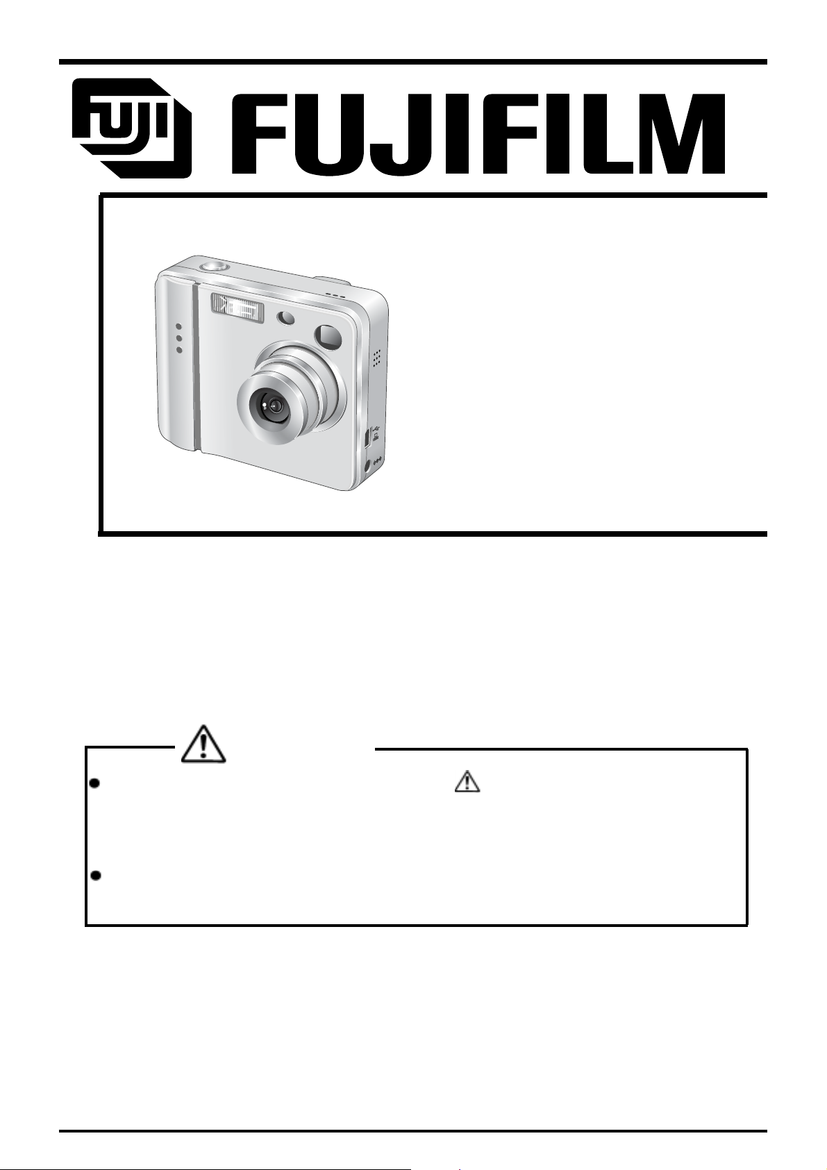
DIGITAL CAMERA
FinePix F401
SERVICE MANUAL
U/E/EG-Model
WARNING
THE COMPONENTS IDENTIFIED BY THE MARK “ ” ON THE SCHEMA TIC
DIAGRAM AND IN THE PARTS LIST ARE CRITICAL FOR SAFETY.
PLEASE REPLACE ONL Y BY THE COMPONENTS SPECIFIED ON THE SCHEMATIC
DIAGRAM AND IN THE P ARTS LIST.
IF YOU USE PARTS UN-SPECIFIED, IT MAY RESULT IN A FIRE AND AN
ELECTRICAL SHOCK.
Ref.No.:ZM00444-103
FUJI PHOTO FILM CO.,LTD.
Printed in Japan 2004.08(S.S.)

SAFETY CHECK-OUT
After correcting the original problem, perform the following
safety check before returning the product to the customer.
FinePix F401 Service Manual
1. Check the area of your repair for unsoldered or
poorly soldered connections. Check the entire
board surface for solder splasher and bridges.
2. Check the interboard wiring to ensure that no
wires are “pinched” or contact high-wattage
resistors.
3. Look for unauthorized replacement parts, particularly transistors, that were installed during a
previous repair. Point them out to the customer
and recommend their replacement.
4. Look for parts which, though functioning, show
obvious signs of deterioration. Point them out to
the customer and recommend their replacement.
5. Caution:
For continued protection against
2.5A 125/250V
2.5A 125/250V
RISK OF FIREREPLACE FUSE
AS MARKED
fire hazard, replace only with same
type 2.5 amperes 125/250 volts
fuse.
Attention:
Afin d’assurer une protection
permanente contre les risques
d’incendie, remplacer uniquement
par un fusible de meme, type 2.5
amperes, 125/250 volts.
6. Warning:
To reduce the electric shock, be
WARNING!
HIGH VOLTAGE
careful to touch the parts.
2

FinePix F401 Service Manual
TABLE OF CONTENTS
TABLE OF CONTENTS
1. General
1-1.Product Specifications ........................................................... 4
1-2.Camera Features ..................................................................... 6
1-3.Names of External Components ............................................ 8
2.Disassembly
2-1. Internal Components ............................................................. 9
2-2. Removing the R PANEL ASSY.......................................... 10
2-3. Removing the KEY FPC ASSY.......................................... 10
2-4. Removing the F PANEL ASSY .......................................... 1 1
2-5. Removing the BARRIER MOTOR ASSY ........................... 11
2-6. Removing the FRONT FPC ASSY..................................... 12
2-7. Removing the CABI.BOTTOM ASSY ................................ 12
2-8. Removing the LENS UNIT .................................................. 1 3
2-9. Removing the MAIN PWB ASSY ....................................... 1 3
2-10.Removing the FLASH UNIT ............................................... 1 4
2-11.Removing the LCD UNIT ..................................................... 15
2-12.Removing the BATTERY CONNECTOR ASSY ................ 15
3.Circuit Diagrams
3-1. Cautions ............................................................................... 16
3-2. Basic Block Names and Functions .................................. 16
3-3. Functions of Primary Blocks............................................. 17
3-3-1.Technical Outline .............................................................. 17
3-3-2.Block Functions................................................................. 17
3-4. Block Diagram ..................................................................... 19
3-5. MAIN PWB ASSY Mounting Diagram ............................... 2 1
5.Final Inspection
5-1. Preparations for Inspection .............................................. 4 3
5-1-1.Measuring Devices ........................................................... 43
5-1-2.Jigs ..................................................................................... 4 3
5-1-3.Connections ...................................................................... 44
5-2. Inspections .......................................................................... 45
5-2-1.External Inspections ......................................................... 45
5-2-2.Power Supply Switch Check .......................................... 4 5
5-2-3.Checking Movie Mode Shock Noise ............................... 4 5
5-2-4.Checking Resolution ......................................................... 45
5-2-5.Y Level Check ................................................................... 4 6
5-2-6.Checking Strobe Photography ........................................ 4 6
5-2-7.Checking Movie and Audio .............................................. 4 7
5-2-8.Checking the Erase Mode ................................................ 4 7
5-2-9.Checking for Low Battery ............................................... 47
5-2-10.Checking Current Consumption .................................... 4 7
5-2-11.Checking the LCD Display Image ................................. 4 7
5-2-12.Settings at Shipment ...................................................... 4 8
5-2-13.Clearing Time Setup ....................................................... 48
6.Parts List
6-1-1.Packing and Accessories(U model) .............................. 49
6-1-2.Packing and Accessories(E model) ............................... 5 0
6-1-3.Packing and Accessories(EG model) ............................ 51
6-2.Cabinet F block (U/E/EG model) ......................................... 52
6-3.Cabinet R block (U/E/EG model) ......................................... 53
6-4.Electrical Parts (U/E/EG model) .......................................... 54
7. Appendix
4.Adjustments
4-1. Adjustment Items and Procedures when Replacing
Primary Parts ...................................................................... 2 2
4-2. Measuring Devices ............................................................ 22
4-3. Jigs ....................................................................................... 22
4-4. Jig Connections .................................................................. 23
4-5. Environment Setup ............................................................. 23
4-6. Installing the Jig Drivers on the PC .................................. 24
4-7. Installing and Starting the Adjustment Software .................. 25
4-8. Initializing the Adjustment Software................................ 25
4-9. Starting the Adjustment Software ................................... 28
4-10.CCD data input .................................................................... 30
4-11.Camera adjustment ............................................................ 32
4-12.AF adjustment ..................................................................... 34
4-13.Battery voltage adjustment ............................................... 3 5
4-14.Flash adjustment ................................................................ 37
4-15.Firmware Download .......................................................... 3 8
4-16.End Setting .......................................................................... 40
7-1.List of Related Technical Updates Issued........................ 55
3

1.General
FinePix F401 Service Manual
1. General
1-1. Product Specifications
System
Model Digital camera FinePix F401
Number of effective pixels
CCD sensor 1/2.7-inch Super CCD in an interwoven pattern
Number of recorded 2304 × 1728 pixels (4.0 million pixels)/1600 × 1200 pixels/ 1280 × 960 pixels/640 ×
pixels 480 pixels
File format Still image: JPEG (Exif ver. 2.2)
Storage media SmartMedia (3.3V)
Viewfinder Real image optical Approx. 80% coverage
Lens Super EBC Fujinon optical 3× zoom lens
Aperture F2.8-F4.8/F7-F11.6 (automatically selected)
Focus TTL contrast-type, Auto focus
Focus distance f = 5.7 mm-17.1 mm
Exposure control TTL 64-zones metering, Program AE, exposure compensation available in Manual
Sensitivity Equivalent to ISO 200/400/800/1600
White balance Auto (In Manual modes, 7 positions can be selected.)
Focal range Normal: Approx. 60 cm (2.0 ft.) to infinity
Shutter Variable-speed, 1/4 sec. to 1/2000 sec. (depend on Exposure mode)
Flash Auto flash using flash control sensor
Erase modes ERASE FRAME, ERASE ALL FRAMES, FORMAT (initialize)
LCD monitor 1.5-inches, low-temperature polysilicon TFT 114,000 pixels
Self-Timer 10 sec. timer clock
zStandard number of available shots/recording time per SmartMedia
Quality
No. of recorded pixels 2304 × 1728 1600 × 1200 1280 × 960 640 × 480 Movie
Image Data Size
MG-4S (4MB) 2 4 9 12 30
MG-8S (8MB) 4 9 19 25 61
MG-16S/SW (16MB) 9 19 39 49 122
MG-32S/SW (32MB) 20 39 79 99 247
MG-64S/SW (64MB) 40 79 159 198 497
MG-128SW (128MB) 81 159 319 398 997
2.1million pixels
Number of total pixels 2.11 million pixels
* Design rule for Camera File System compliant, DPOF compatible
Movie: AVI format, Motion JPEG
Audio: WAV format
(Equivalent to 38 mm-114 mm on a 35 mm camera)
photography mode
Macro: Approx. 10 cm (0.3 ft.) to 80 cm (2.6 ft.)
Effective range: Wide-angle Approx. 0.4 m-3.5 m (15.7 in.-11.5 ft.)
Telephoto Approx. 0.4 m-2 m (15.7 in.-6.6 ft.)
Flash modes: Auto, Red-Eye Reduction, Forced Flash, Suppressed Flash, Slow
Synchro
4M • F
Approx. 1.6MB Approx. 790KB Approx. 390KB Approx. 320KB Approx. 130KB
4M • N
2M
1M
0.3M
__ __
Approx. 24 sec. Approx. 83 sec.
Approx. 49 sec. Approx. 169 sec.
Approx. 98 sec. Approx. 5.6 min.
Approx. 199 sec. Approx. 11.3 min.
Approx. 6.7 min. Approx. 22.8 min.
Approx. 13.4 min. Approx. 45.6 min.
Input/Output Terminals
DC Input To connect the AC power Adapter AC-5VS/AC-5VHS
(USB) socket For file transfer to a computer and connection to the optional cradle
4

FinePix F401 Service Manual
1.General
Power Supply and Others
Power supply Use one of the following
*Rechargeable Battery NP-60 or AC Power Adapter AC-5VS/AC-5VHS
Available shots using
the battery
(When fully charged)
The number of shots shown here is an approximate guide to the number of consecutive shots that can be taken based on 50% flash usage at normal temperatures. However, the actual number of available shots will vary depending on the
ambient temperature when the camera is used and the amount of charge in the
battery. The number of available shots will be lower in cold conditions.
Conditions for use Temperature: 0oC to +40oC (+32oF to +104oF) 80% humidity or less (no condensation)
Camera dimensions 85.0 mm × 69.4 mm × 27.5 mm/3.3 in. × 2.7 in. × 1.1 in.
(W/H/D) (not including accessories and attachments)
Camera mass (weight) 185 g/6.5 oz. (not including accessories, batteries or SmartMedia)
Weight for photography Approx. 215 g/7.6 oz. (including battery and SmartMedia)
Accessories z SmartMedia (16MB, 3.3V) (1)
z NP-60 Rechargeable Battery (1)
z Strap (1)
z AC-5VS/AC-5VHS AC Power Adapter (1)
z USB Interface Set (1)
z Owner’s Manual (1)
Optional accessories z SmartMedia
z BC-60 Battery Charger
z NP-60 Rechargeable Battery
z AC-5VH/AC-5VHS AC Power Adapter
z PictureCradle CP-FX401
z SC-FX401
z FD-A2 Floppy Disk Adapter (FlashPath)
z SM-R2 Image Memory Card Reader
z DM-R1 Image Memory Card Reader
z PC-AD3 PC Card Adapter
NP-60
Supplied with: Anti-static case (1)
Soft case included
Approx. 2 m (6.6 ft.) connection cord
CD-ROM: Software for FinePix EX (1)
FinePix F401 Special USB cable with Noise Suppression core (1)
Software Quick Start Guide (1)
MG-4S: 4MB, 3.3V MG-8S: 8MB, 3.3V MG-16S: 16MB, 3.3V
MG-32S: 32MB, 3.3V MG-64S: 64MB, 3.3V
MG-16SW: 16MB, 3.3V, ID MG-32SW: 32MB, 3.3V, ID
MG-64SW: 64MB, 3.3V, ID MG-128SW: 128MB, 3.3V, ID
Windows 95/98/98 SE/Me/NT4.0
Mac OS 7.6.1 to 9.1
Compatible with Windows 98/98 SE, Windows Me, Windows 2000 Professional
or iMac and models that support USB as standard.
Compatible with Windows 98 SE, Windows 2000 Professional (read-only), iMac DV
and Power Macintosh PCs with FireWire as a standard feature. Mac OS 8.5.1 to 9.1
Battery Type No. of Shots
LCD monitor ON
LCD monitor OFF
Index label (1)
Approx. 200
Approx. 450
5

1.General
FinePix F401 Service Manual
1-2. Camera Features
z 2.1 million effective pixels
z 1/2.7-inch Super CCD provides high quality images with 2304 × 1728 (4.0 million) recorded pixels
z High-performance 3× optical zoom
z Compact and lightweight aluminum-magnesium alloy body
z Quick, responsive operation with a 2.5-second startup and 1.3 seconds between shots.
z Auto focus with macro function
z Manual photography mode lets you set your own photography settings.
z High-sensitivity photography ( mode only)
z Image checking function automatically plays back the image for about 2 seconds after you take a picture.
z Maximum 3.6× seamless digital zoom
z Playback zoom function (up to 14.4× )
z Continuous shooting function
z Movie shooting function (with sound)
z Voice Memo function for easy photography information recording
z 1.5-inches 114,000-pixels low-temperature polysilicon TFT LCD monitor
z Recharge or connect to your PC simply by placing the FinePix F401 in its cradle (sold separately)
z Easy high-speed image file transfer via the USB connection
z Conforms to "Design for Camera File system" standard and Exif ver 2.2 for digital cameras
*"Design for Camera File system" standard and Exif format are formulated by the Japanese Electronic
and Information Association (JEITA)
1-2. Explanation of Terms
DPOF: Digital Print Order Format
DPOF is a format used for recording information on a storage media (image
memory card, etc.) that allows you to specify which of the frames shot using a
digital camera are printed and how many prints are made of each image.
EV: A number that denotes Exposure Value. The EV is determined by the brightness of
the subject and sensitivity (speed) of the film or CCD. The number is larger for
bright subjects and smaller for dark subjects. As the brightness of the subject
changes, a digital camera maintains the amount of light hitting the CCD at a constant level by adjusting the aperture and shutter speed.
When the amount of light striking the CCD doubles, the EV increases by 1. Likewise, when the light is halved, the EV decreases by 1.
JPEG: Joint Photographics Experts Group
A file format used for compressing and saving color images. The compression ratio
can be selected, but the higher the compression ratio, the poorer the quality of the
expanded image.
Motion JPEG: A type of AVI (Audio Video Interleave) file format that handles images and sound as
a single file. Images in the file are recorded in JPEG format. Motion JPEG can be
played back by QuickTime 3.0 or later.
PC Card: A generic term for cards that meet the PC Card Standard
PC Card Standard: A standard for PC cards determined by the PCMCIA.
PCMCIA: Personal Computer Memory Card International Association (US).
6

FinePix F401 Service Manual
WAVE: A standard format used on Windows systems for saving audio data. WAVE files have
the ".WAV" file extension and the data can be saved in either compressed or
uncompressed format. Uncompressed recording is used on this camera.
WAVE files can be played back on a personal computer using the following software:
Windows: MediaPlayer
Macintosh: QuickTime Player * QuickTime 3.0 or later
White Balance: Whatever the kind of the light, the human eye adapts to it so that a white object still
looks white. On the other hand, devices such as digital cameras see a white subject as white by first adjusting the color balance to suit the color of the ambient
light around the subject. This adjustment is called matching the white balance. A
function that automatically matches the white balance is called an Automatic
White Balance function.
1.General
7

1.General
1-3.Names of External Components
FinePix F401 Service Manual
Shutter button
Flash
Self-timer lamp
POWER switch
Flash control sensor
Microphone
Viewfinder window
Speaker
Lens/Lens cover
(USB) socket
Cradle connection
socket
DC IN 5V (power input)
socket
/Macro button
( ) ( )/Zoom button
/Flash button
Mode switch
Viewfinder
Viewfinder lamp
LCD monitor
Tripod mount
Battery cover
MENU/OK button
BACK button
DISP button
Strap mount
Battery compartment
Battery release catch
SmartMedia eject button
SmartMedia slot
8
FinePix F401 Service Manual
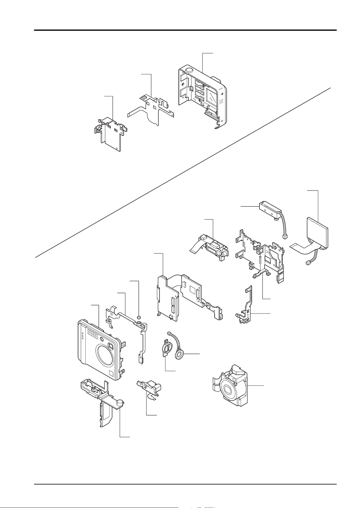
2. Disassembly
2-1. Internal Components
KEY PWB ASSY
BATTERY FRAME
2. Disassembly
R PANEL ASSY
LCD UNIT
FRONT FPC ASSY
F PANEL ASSY
BATTERY CONNECTOR ASSY
FLASH UNIT
MAIN PWB ASSY
MICROPHONE
MAIN FRAME ASSY
TRIPOD FRAME
SPEAKER ASSY
SP RUBBER
BARRIER MOTOR UNIT
CABI.BOTTOM ASSY
LENS ASSY
9

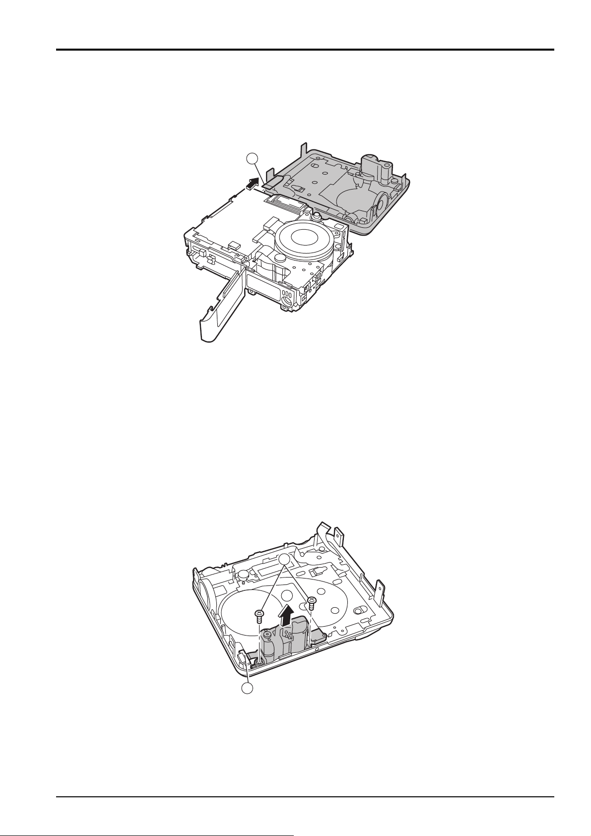
2. Disassembly
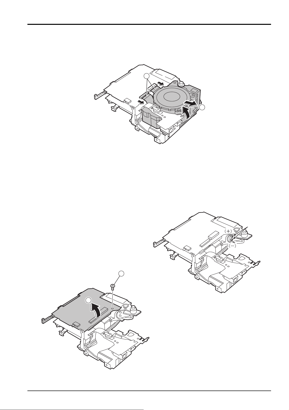
2-2. Removing the R PANEL ASSY
FinePix F401 Service Manual
[Removal]
1 Remove the six M1.7x3.5 screws and the M1.4x5.5
screw.
2 Open the battery cover.
3 Raise the R PANEL ASSY in the direction of the
arrow.
4 Remove the FFC (see below for removal of the
FFC).
4
1
1
3
2
[Assembly]
Assemble in the reverse order to removal.
1
2-3. Removing the KEY FPC ASSY
[Removal]
1 Remove the two M1.7x2.5 screws.
2 Peel off the double-sided tape.
3 Remove the battery frame in the direction of the
arrow.
4 Peel off the three pieces of double-sided tape, and
remove the KEY FPC ASSY.
1
2 Double-sided tape
2
㕙࠹ࡊ
3
[Assembly]
Assemble in the reverse order to disassembly.
10
㕙࠹ࡊ
4
4 Double-sided tape
FinePix F401 Service Manual
2. Disassembly
2-4. Removing the F PANEL ASSY
[Removal]
1 Raise the F PANEL ASSY as shown in the diagram
and remove the FFC.
1
2-5. Removing the BARRIER MOTOR
ASSY
[Removal]
1 Remove the connector lock.
2 Remove the two M1.75x2.5 screws.
3 Remove the BARRIER MOTOR ASSY in the direc-
tion of the arrow.
2
3
[Assembly]
Assemble in the reverse order to disassembly.
1
[Assembly]
Assemble in the reverse order to disassembly.
11
2. Disassembly
2-6. Removing the FRONT FPC ASSY
FinePix F401 Service Manual
[Removal]
1 Remove the connector.
2 Remove the SPEAKER ASSY.
3 While removing the double-sided tape, remove it
from the rib on the case.
4 Remove the two M1.75x2.5 screws.
5 Remove the M1.75x2.5 screw.
6 Remove the flexible connector rearwards.
5
6
2
1
4
Double-sided tape
㕙࠹ࡊ
[Assembly]
Assemble in the reverse order to disassembly.
3
Double-sided
㕙࠹ࡊ
tape
2-7. Removing the CABI.BOTTOM
ASSY
[Removal]
1 Remove the M1.75x3 screw.
2 Raise the connector board.
3 Remove the engagement and remove the TRIPOD
FRAME in the direction of the arrow.
4 Raise the Smart Media removal button.
5 Remove the CABI.BOTTOM ASSY in the direction
of the arrow.
4
3
5
1
2
12
Engagement part
፰วㇱ
[Assembly]
Assemble in the reverse order to removal.
FinePix F401 Service Manual
2. Disassembly
2-8. Removing the LENS UNIT
[Removal]
1 Remove the two flexible connectors.
2 Remove the LENS UNIT.
1
2
2-9. Removing the MAIN PWB ASSY
Note:
Always ensure that the FLASH ASSY main condenser is
discharged before beginning disassembly.
[Removal]
1 Remove the M1.7x3 screw.
2 Remove the board in the direction of the arrow.
1
2
[Assembly]
Assemble in the reverse order to disassembly.
࠺ࠖࠬ࠴ࡖࠫ
ࡐࠗࡦ࠻
Discharge point
13
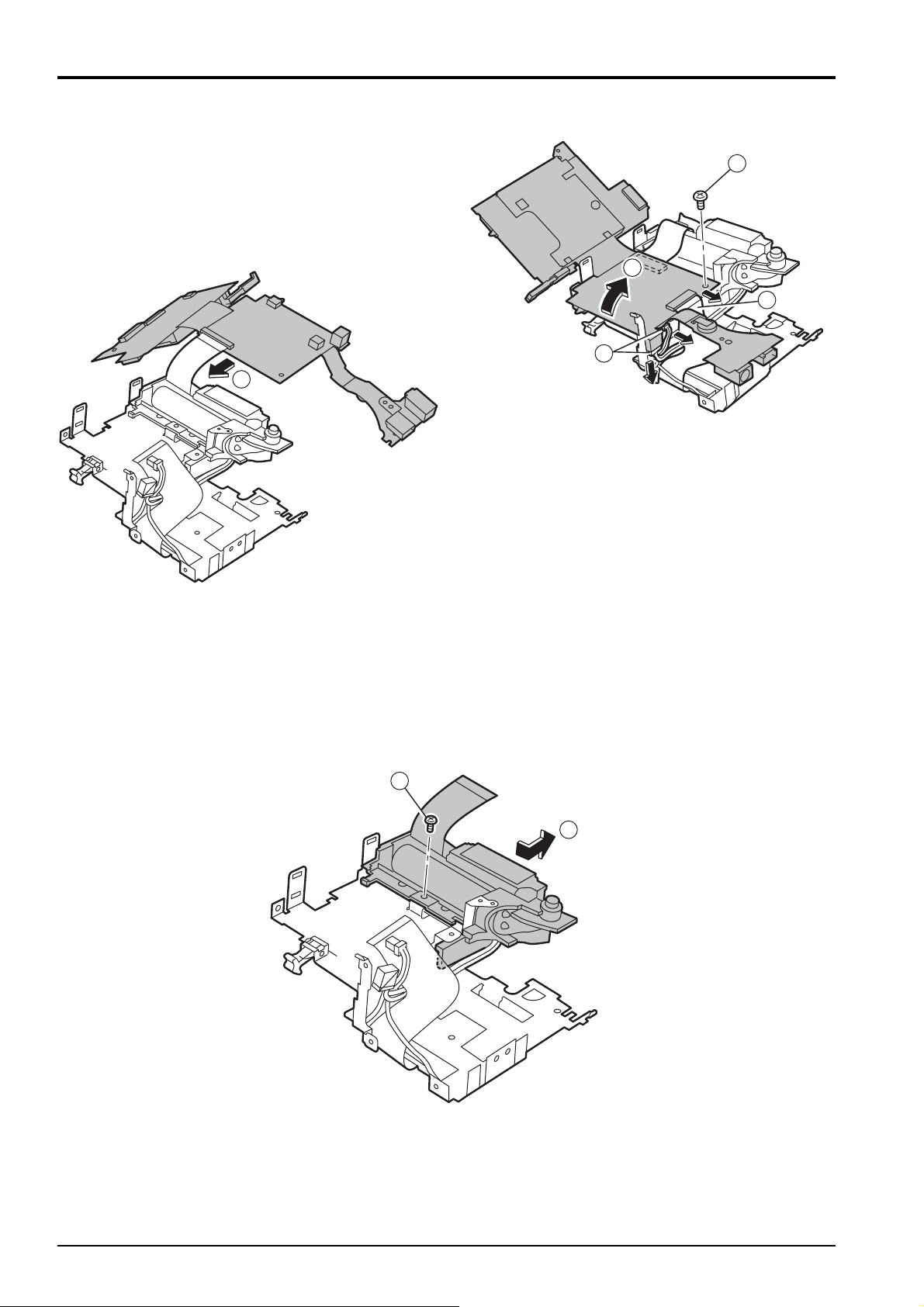
2. Disassembly
3 Remove the LCD flexible connector.
4 Remove the lead wire.
5 Remove the M1.7x3 screw.
6 Raise the board in the direction of the arrow.
7 Remove the strobe flexible connector, and remove
the MAIN PWB ASSY.
7
FinePix F401 Service Manual
5
6
3
4
2-10. Removing the FLASH UNIT
[Removal]
1 Remove the M1.7x3 screw.
2 Remove the FLASH UNIT in the direction of the
arrow.
[Assembly]
Assemble in the reverse order to disassembly.
1
2
14
[Assembly]
Assemble in the reverse order to disassembly.
FinePix F401 Service Manual
2. Disassembly
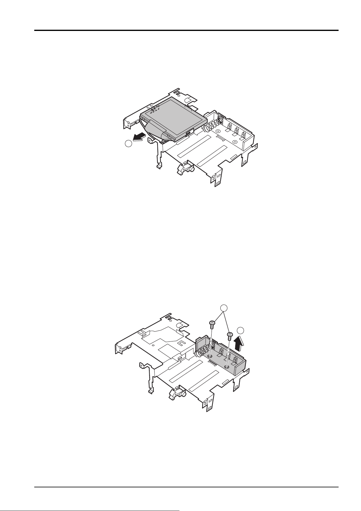
2-11. Removing the LCD UNIT
[Removal]
1 Slide the LCD UNIT in the direction of the arrow,
and remove it.
1
2-12. Removing the BATTERY CONNEC-
TOR ASSY
[Removal]
1 Remove the two M1.7x3 screws.
2 Remove the BATTERY CONNECTOR ASSY.
[Assembly]
Assemble in the reverse order to removal.
1
2
[Assembly]
Assemble in the reverse order to removal.
15

3. Schematics
FinePix F401 Service Manual
3. Circuit Diagrams
3-1. Cautions
<Cautions when replacing parts>
• Do not reuse removed parts. Always use new parts.
• Note that the -ve side of tantalum condensers is readily damaged by heat.
• Except for chemical condensers and tantalum condensers, voltage is not displayed on condensers with a voltage
resistance of 50V or less.
• Resistors not marked are 1/16W chip resistors.
• KW = 1000Ω, MW = 1000KΩ
• B characteristics of variable resistors and semi-fixed resistors are not displayed.
3-2. Basic Block Names and Functions
Part name Block name Function
LENS CONST CCD BLOCK CCD output
MAIN PWB ASSY CAM BLOCK CCD output A/D conversion (IC103)
CCD driver (IC101, IC102)
PROCESS BLOCK Image signal processing, USB communications,
system control (IC302)
MOTOR BLOCK Shutter/iris/AF/zoom drive (IC203)
POWER ON BLOCK Power supply management (IC252)
LCD BLOCK LCD control (IC452)
AUDIO BLOCK Audio signal processing (IC402)
DC/DC BLOCK Power supply generation (IC501)
CHG BLOCK Li battery charging control (IC654)
STRB BLOCK Strobe charging control (IC602)
KEY PWB ASSY KEY BLOCK Switches (TELE/WIDE, DISP, MENU/OK, LED etc)
FLASH UNIT FLASH BLOCK Strobe
16

FinePix F401 Service Manual
3. Schematics
3-3. Functions of Primary Blocks
3-3-1. Technical Outline
The FinePix F401 incorporates the new generation [Super CCD Honeycomb III], and two new ICs - the [Intelligent
Highly Integrated Image Processor IC (VCS2; IC302)], and the [Power Supply Management IC (PWR_ON_IC;
IC252)].
The [Intelligent Highly Integrated Image Processor IC (VCS2; IC302)] is the equivalent of the [Image Signal Processing IC (MD2305; IC204; CSP)] in the previous FinePix 2500Z. The new IC allows a major reduction in photography
and playback interval time, and also contributes to better S/N ratio and sharpness, and thus to improvements in image
quality.
Software-controlled USB communications, and the use of a VCS internal buffer, provides for a reduction in data transmission time.
3-3-2. Block Functions
(1) CCD signal processing/photography circuit (CCD BLOCK) (CAM BLOCK)
The analog video signal output from the CCD (1/2.7", 2,100,000-pixel super CCD Honeycomb III) is subject to
pseudo-color compensation processing (CDS), adaptive interpolation processing (CDS), amplified (AGS), and
signal mixing (CDS) in the single chip CSP_IC (IC103; SCS3A)*, and is then A/D converted to a 12-bit digital
signal. The CSP_IC incorporates the [TG and SSG functions] previously supported by discrete ICs.
The converted digital signal is sent to the Intelligent Highly Integrated Image Processor IC (VCS2; IC302).
(* CSP_IC - Chip Size Package IC)
This block incorporates an OFD control IC (IC 101) and a horizontal/vertical drive IC (IC102) for CCD drive.
(2) Motor circuit (MOTOR BLOCK)
The signal processing system IC (VCS2; IC302) receives commands from the switches, manages the motor drive
IC (IC 203), and controls the AF, SHUTTER, ZOOM, and IRIS motors.
(3) Image signal processing (PROCESS BLOCK)
(Input data from CCD)
The 12-bit digital image data (equivalent to 1H) output from the CCD_CAM BLOCK is sent to the Intelligent Highly
Integrated Image Processor IC (VCS2; IC302), buffered in the [internal buffer], and converted to 32-bit (16-bitx2)
data (CCD RAW data). The converted 32-bit image data (CCD RAW data) is sent to two 16Mbyte SDRAMs (IC303,
IC304) via the [I/O bus] in the image signal processing IC for temporary storage (a single frame equivalent (1600
pixels x 1200 lines) of image data is temporarily stored in the SDRAMs).
It is calculated in the [AUTO COMPUTE BLOCK] using the 32-bit image data input to the Intelligent Highly Inte-
grated Image Processor IC (VCS2; IC302) and sent to the SCS3A_IC (IC103) in the CAM BLOCK to obtain the
optimum AE, AWB, and AF.
(Recording in the SSFDC)
Image data stored in the SDRAMs (IC303, IC304) is sent one line at a time to the [PROCESS BLOCK] via the [I/O
bus] in the Intelligent Highly Integrated Image Processor IC (VCS2; IC302). This data is unpacked (converted
from 32-bit to 12-bit data) in the [PROCESS BLOCK], preprocessed (digitally clamped, ƒÁ compensated, each of
R, G, and B 12-bit data converted to 8-bit data), each of the digital R, G, and B 8-bit signals YC processed (Y:Cb:Cr
ratio adjusted to 4:2:2), and each of the Y, Cr, and Cb 8-bit image data sent to the [internal buffer] again. In the
internal buffer, each of the Y, Cr, and Cb 8-bit signals are sorted into a format readily subject to DCT compression,
sent via the [JPEG COMPUTE BLOCK] and [media controller] and recorded in the SSFDC.
(Image data playback from the SSFDC)
Compressed image data from the SSFDC is sent as 8-bit image data to the Intelligent Highly Integrated Image
Processor IC (VCS2; IC302), and then sent to the SDRAMs (IC303, IC304) via the [media control unit], [DMA unit],
and [internal bus control unit]. The image data temporarily stored in the IC(IC303,IC304) is returned to the Intelli-
gent Highly Integrated Image Processor IC (VCS2; IC302), and sent to the [PROCESS BLOCK] via the [media
controller] and [JPEG COMPUTE BLOCK]. Each of the Y, Cr, and Cb 8-bit image data signals are post-processed
(converted to 8-bit R, G, and B signals) in the [PROCESS BLOCK], text display signals superimposed, and sent to
the LCD BLOCK.
Photography adjustment data is stored in the FLASH ROM (IC305).
(4) LCD control (LCD BLOCK)
The R, G, and B digital signals input to the [LCD BLOCK] IC (IC452) from the Intelligent Highly Integrated Image
Processor IC (VCS2; IC302) are sent directly to the LCD drive IC for LCD drive and LCD panel brightness control.
(5) Power supply (DCDC BLOCK)
The power supply circuit on the DC board supplies 1.5V [VCS (IC302)], 3.3V [VCS (IC302), FLASH_ROM (IC305),
SDRAM (IC304/IC305), KEY PWB, MRSW PWB SSFDC, POWER_ON_IC (IC252), STRB], CAM_3.3V
(CAM_BLOCK), MOT_3.3V (MOTOR_BLOCK), MOT_5.2V (MOTOR_BLOCK, BL_BLOCK, AUDIO_BLOCK), -8V
(CCD), -8.5V (LCD), 12V (BL_BLOCK), 16V (CCD, LCD), and UNREG.
17
 Loading...