

FUJIFILM FinePix F11 SERVICE MANUAL
DIGITAL CAMERA
FinePix F11
SERVICE MANUAL
US/EU/EG/EE/AS/CH/JP-Model
CAUTION
BECAUSE THIS PRODUCTIS RoHS LEAD-FREE COMPLIANT, USE THE DESIG-
NATED AFTER-SELES PARTS AND THE DESIGNATED LEAD-FREE SOLDER WHEN
PERFORMING REPAIRS. (Refer to page 3 to page 5)
WARNING
THE COMPONENTS IDENTIFIED WITH THE MARK “ ” ON THE SCHEMATIC
DIAGRAM AND IN THE PARTS LIST ARE CRITICAL FOR SAFETY.
PLEASE REPLACE ONLY WITH THE COMPONENTS SPECIFIED ON THE SCHEMATIC
DIAGRAM AND IN THE PARTS LIST.
IF YOU USE PARTS NOT SPECIFIED, IT MAY RESULT IN A FIRE AND AN
ELECTRICAL SHOCK.
FUJI PHOTO FILM CO., LTD.
Ref.No.: ZM00615-100
Printed in Japan 2005.11
FinePix F11 Service Manual
SAFETY CHECK-OUT
After correcting the original problem, perform the following
safety check before return the product to the customer.
1. Check the area of your repair for unsoldered or poorly
soldered connections. Check the entire board surface
for solder splasher and bridges.
2. Check the interboard wiring to ensure that no wires are
“pinched” or contact high-wattage resistors.
3. Look for unauthorized replacement parts, particularly
transistors, that were installed during a previous repair.
Point them out to the customer and recommend their
replacement.
4. Look for parts which, though functioning, show obvious
signs of deterioration. Point them out to the customer
and recommend their replacement.
5. Check the B + voltage to see it is at the values
specified.
6. Make leakage - current measurements to determine
that exposed parts are acceptably insulated from the
supply circuit before returning the product to the
customer.
7. CAUTION: FOR CONTINUED
PROTECTION AGAINST FIRE
HAZARD, REPLACE ONLY WITH
SAME TYPE 2.5 AMPERES 125V
FUSE.
2.5A 125V
2.5A 125V
8. WARNING:
RISK OF FIREREPLACE FUSE
AS MARKED
ATTENTION: AFIN D'ASSURER
UNE PROTECTION
PERMANENTE CONTRE LES
RISQUES D'INCENDIE,
REMPLACER UNIQUEMENT
PAR UN FUSIBLE DE MEME,
TYPE 2.5 AMPERES, 125 VOLTS.
TO REDUCE THE ELECTRIC
SHOCK, BE CAREFUL TO
TOUCH THE PARTS.
WARNING!
HIGH VOLTAGE
2

FinePix F11 Service Manual
RoHS lead-free compliance
Because this product is RoHS lead-free compliant, use the designated after-sales parts and the designated lead-free solder
when performing repairs.
<Background & Overview>
With the exception of parts and materials expressly excluded from the RoHS directive (*1), all the internal connections and
component parts and materials used in this product are lead-free compliant (*2) under the European RoHS directive.
*1: Excluded items (list of the main lead-related items)
• Lead included in glass used in fluorescent tubes, electronic components and cathode-ray tubes
• Lead in high-melting-point solder (i.e. tin-lead solder alloys that contain 85% lead or more)
• Lead in ceramic electronic parts (piezo-electronic devices)
• Mercury contained in fluorescent tubes is also excluded.
*2: Definition of lead-free
A lead content ratio of 0.1 wt% or less in the applicable locations (solder, terminals, electronic components, etc.)
<Reference>
RoHS: The name of a directive issued by the European Parliament aimed at restricting the use of
certain designated hazardous substances included in electrical and electronic equipment.
Designated substances (6): Lead, mercury, cadmium, hexavalent chromium, polybrominated biphenyls (PBBs) and
polybrominated diphenyl ether (PBDE)
<Lead-free soldering>
When carrying out repairs, use a designated lead-free solder, bearing in mind the differing work practices for conventional
solder (eutectic) and lead-free solder.
Differences in the soldering work for lead-free and eutectic solder
When the soldering work practices for eutectic solder and lead-free solder are compared, the main differences are as shown
below. In particular, when lead-free solder is used, the solder tends to be less workable than when eutectic solder is used.
Accordingly, the soldering techniques used must take that into account.
Difference
1
The solder starts melting later.
Poor wetting
2
Solder feed rate is difficult to control.
3
Wetting the insides of through holes is especially
4
difficult.
5
During repairs (or modifications) removing solder
from inside through holes is difficult.
There is serious carbonization of the soldering iron.
6
The surface is not glossy.
7
The initial melting point of lead-free solder is high, so you
have to get used to it.
Move the tip of the soldering iron around to heat the entire
connection to the melting temperature and assist wetting.
Use the solder (wire) diameter and soldering iron that are
best suited to connection being soldered.
First apply solder to the area immediately around the
through hold and then feed the solder into the hole.
Use a suitable wicking wire (with a suitable method and
heating) and a suction tool.
Either put solder onto the soldering iron tip after completing
the work, or turn the iron off frequently.
Learn to recognize the appearance of the surface.
Countermeasure
3
FinePix F11 Service Manual
Setting temperature during lead-free soldering
• Lead-free solder melting temperature
The melting point of eutectic (Sn-Pb) solder is 183°C, while the melting point of lead-free solder (Sn-Ag-Cu) is 30°C higher
at 220°C.
• Soldering iron tip temperature
The temperature setting for the soldering iron used should be such that the tip of the soldering iron is at the correct
bonding temperature for the connection. This temperature is normally set at around 100°C higher than the melting point of
the solder.
However, the actual temperature should take into account the shape and size of the soldering iron tip, the heat tolerance
of the connection and the workability of that temperature.
• Correct bonding temperature
The correct bonding temperature refers not to the temperature of the heat source, but to the bonding temperature that will
give the best bond strength.
Precautions when soldering with lead-free solder
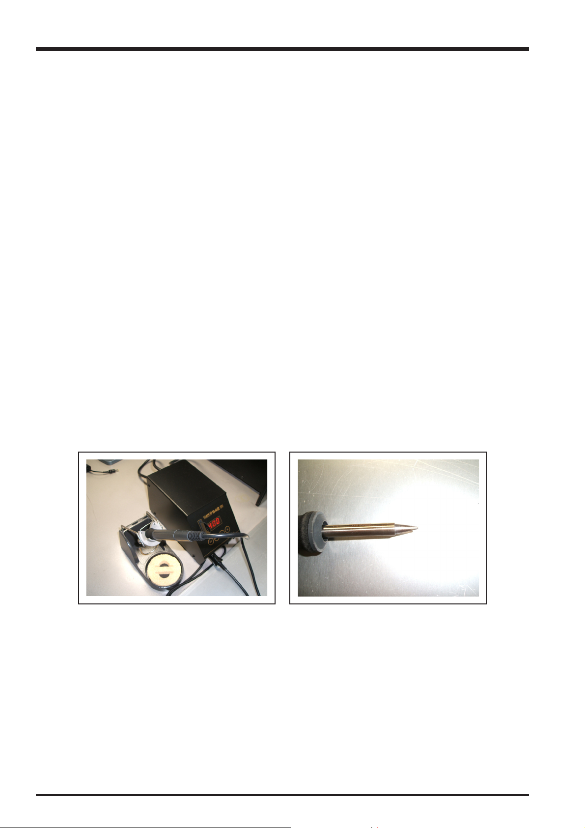
• Soldering iron maintenance
Because of the high soldering iron temperature in lead-free soldering, there is rapid carbonization of the flux adhering to
the tip of the soldering iron.
(1) Always cover the tip of the soldering iron with solder when it is not being used.
(2) If the tip is black from carbonization, wipe it gently with a paper towel soaked in alcohol until the solder will wet.
• Uniform heating of the board and components
To ensure that the lead-free solder wets the entire surface of the pattern and the lands despite its poor wetting
characteristics, you must move the tip of the soldering iron over a wide area to raise the temperature of the entire
connection.
Soldering iron
A soldering iron with a temperature control is best.
4

FinePix F11 Service Manual
Solder wire (thread)
Use the lead-free solders specified below.
Solder type: Sn96.5Ag3Cu0.5 (Displayed symbol: SnAgCu)
Wire diameter: 0.6, 0.8 or 1.0 mm
Sample:
CONTENTS
lead-free
Wire diameter 0.8mm
Solder type (Displayed symbol)
SnAgCu
Flux
Conventional flux can be used.
Solder application wires (mesh, wicking wire, etc.)
Conventional application wires can be used.
5

CONTENTS
FinePix F11 Service Manual
CONTENTS
1. General ............................................................ 7
1-1. Product specification ...............................................7
1-2. Explanation of Terms .............................................10
1-3. Names of External Components ............................ 11
2. Disassembly .................................................. 12
2-1. Names of internal Components ............................. 12
2-2. Removing the R PANEL CONST........................... 13
2-3. Removing the INNER BLOCK ............................... 14
2-4. Removing the ST CONST ..................................... 15
2-5. Removing the BATT HOLDER CONST ................. 15
2-6. Removing the LENS ASSY ...................................16
2-7. Removing the LCD CONST .................................. 16
2-8. Removing the OPE UNIT ......................................17
3. Schematics .................................................... 19
3-1. Cautions ................................................................19
3-2. Basic Block Names and Functions ........................ 19
3-3. Description of Main Block Functions .....................20
3-3-1. Technical Overview ................................. 20
3-4. Block Diagram ....................................................... 21
3-5. Overall connection Diagram .................................. 22
3-6. Circuit Diagrams .................................................... 23
3-6-1. CAMERA BLOCK ................................... 23
3-6-2. DC/DC BLOCK ....................................... 24
3-6-3. KEY BLOCK ........................................... 25
3-6-4. LCD BLOCK ........................................... 26
3-6-5. MOTOR BLOCK ..................................... 27
3-6-6. PMAN BLOCK ........................................ 28
3-6-7. RPOCESS BLOCK .................................29
3-6-8. FLASH BLOCK .......................................30
3-6-9. AFLED BLOCK .......................................31
3-6-10. CCD FPC BLOCK ................................... 31
3-6-11. LED FPC BLOCK ................................... 32
3-6-12. CHG BLOCK ........................................... 32
3-6-13. AUDIO BLOCK ....................................... 33
3-6-14. MEDIA BLOCK ....................................... 34
3-6-15. MULTI BLOCK ........................................ 34
3-6-16. FLASH CN BLOCK ................................. 35
3-6-17. VIDEO BLOCK ....................................... 35
3-7. Mounted Parts Diagrams .......................................36
3-7-1. MOUNT A ASSY ..................................... 36
3-7-2. MOUNT B ASSY ..................................... 37
4. Adjustments ................................................... 38
4-1. Important point Adjustment when
Replacing Major Parts ........................................... 38
4-2. Measuring Instruments Used .................................38
4-3. Use Jig list ............................................................. 38
4-4. Calibration method of pattern box ......................... 39
4-5. Adjusting soft installation ....................................... 39
4-5-1. Various downloading software
decompressions, preservation methods,
and notes ................................................39
4-5-2. Installation of DSC jig driver ................... 40
4-5-3. Adjustment software initiation method .... 40
4-6. Initial Settings of the Adjustment Software ............ 41
4-7. Starting the Adjustment Software .......................... 44
4-8. [R] : Flash Memory Reset ......................................47
4-9. [F4] : CCD Data Input ............................................ 49
4-10. [F5] : Camera Adjustment ...................................... 51
4-11. [F6] : AF Adjustment .............................................. 55
4-12. [F7] : Flash Adjustment .......................................... 58
4-13. [F1] : Battery Voltage Adjustment ..........................60
4-14. [F11] : Video Adjustment ........................................ 64
4-15. [F8] : Firmware Download ..................................... 66
4-16. [F12] : End Setting ................................................. 68
5. Inspection ...................................................... 72
5-1. Required Measuring Equipment ............................ 72
5-2. Connection of Measuring Equipment .................... 72
5-3. Inspection and Factory Settings ............................ 73
6. Parts List ....................................................... 75
6-1. Packing and Accessories ...................................... 75
6-1-1. US-model ................................................ 75
6-1-2. EU-model ................................................ 76
6-1-3. EG-model ................................................ 77
6-1-4. EE-model ................................................78
6-1-5. AS-model ................................................79
6-1-6. CH-model ................................................ 80
6-1-7. JP-model ................................................. 81
6-2. Cabi Front Block .................................................... 82
6-2-1. US/AS/CH/JP-model ............................... 82
6-2-2. EU/EG/EE-model .................................... 83
6-3. Cabi Rear Block .................................................... 84
6-3-1. US/AS/CH/JP-model ............................... 84
6-3-2. EU/EG/EE-model .................................... 85
6-4. Electrical parts ....................................................... 86
7. Appendix ....................................................... 87
7-1. List of Related Technical Updates Issued.............. 87
6

FinePix F11 Service Manual
1. General
1. General
1-1. Product specification
System
Model Digital camera FinePix F11
Effective pixels 6.3 million pixels
CCD 1/1.7-inch Super CCD HR
Storage media xD-Picture Card (16/32/64/128/256/512 MB/1 GB)
File format Still image: DCF-compliant
Compressed: Exif ver.2.2 JPEG, DPOF-compatible
* Design rule for Camera File System compliant DPOF compatible
Movie: AVI format, Motion JPEG
Audio: WAVE format, Monaural sound
×
Number of recorded pixels Still image: 2848
1600
×
Lens Fujinon 3
Focal length f=8 mm-24 mm
(Equivalent to approx. 36 mm-108 mm on a 35 mm camera)
: Equivalent to approx. 37 mm-111 mm on a 35 mm camera)
(
Digital zoom Approx. 6.2× (3× optical zoom lens is used together: Max. zoom scale: approx. 18.5×)
Aperture F2.8 to F8 (Up to 10 steps)
Focal range Normal: approx. 60 cm (2.0ft.) to infinity
Macro: approx. 5 cm (2.0 in.) to 80 cm (2.6 ft.) (wide-angle)
Sensitivity AUTO/Equivalent to ISO 80/100/200/400/800/1600
Photometry TTL 256-zones metering Multi, Spot, Average
Exposure control Program AE, Shutter priority AE, Aperture priority AE
Scene position
Exposure compensation -2 EV to +2 EV in 1/3 EV-step increments ( , S, A)
Shutter speed 3 sec. to 1/2000 sec. (depend on Exposure mode)
Continuous shooting Top 3-frame: Number of recorded frames: up to 3 frames (Max. 2.2 frames/sec.)
Focus Mode: Single-AF, Continuous AF
White balance Automatic scene recognition/Preset (Fine, Shade, Fluorescent (Daylight), Fluorescent
Self-timer Approx. 10 sec./2 sec.
Flash type Auto flash
Flash mode Auto, Red-Eye Reduction, Forced Flash, Suppressed Flash, Slow Synchro, Red-Eye
LCD monitor 2.5 inches, Aspect ratio: 4:3; 153,000 pixels Amorphous silicon TFT, Approx. 100% coverage
* When the scene position is at “
to 15 seconds.
Final 3-frame: Number of recorded frames:
Long-period continuous shooting mode:
AF system: TTL contrast-type
AF frame selection: AF (CENTER), AF (MULTI)
(Warm White), Fluorescent (Cool White), Incandescent)/Custom
Effective range (
Reduction + Slow Synchro
optical zoom lens F2.8-F5
approx. 30 cm (1.0 ft.) to 80 cm (2.6 ft.) (telephoto)
(NATURAL LIGHT), (PORTRAIT), (LANDSCAPE), (SPORT), (NIGHT)
2136 pixels/3024 × 2016 pixels/2048 × 1536 pixels/
×
1200 pixels/640 × 480 pixels ( / / / /
” NIGHT, it is possible to have long exposure times of 1
last 3 frames before releasing the shutter button (Max. 2.2 frames/sec.)
Number of recorded frames: up to 40 frames.1.3 sec. intervals at
depending on quality level. (Max. 0.9 frames/sec.)
: AUTO): Wide-angle: approx. 30 cm-6.5 m (1.0 ft.-21.3 ft.)
Telephoto: approx. 30 cm-4 m (1.0 ft.-13.1 ft.)
)
N
7

1. General
FinePix F11 Service Manual
System
Movie 640 × 480 pixels/320 × 240 pixels ( / )
(30 frames per second with monaural sound)
A series of continuous image can be recorded depending on the available space on an
xD-Picture Card. Zoom cannot be used during movie recording.
Photography functions High-speed shooting, Best framing, Post shot assist window, Frame No. memory
Playback functions Trimming, Automatic playback, Multi-frame playback, Sorting by date, Image rotate, Voice
memo
Other functions PictBridge, Exif print, Language (English, Francais, Deutsch,
Time difference, FinePix photo mode (
-mode)
, Italiano, , ),
Input/Output Terminals
External connection Multi connecter terminal for terminal adapter.
terminal (USB/AC power adapter/Audio visual output)
Power Supply and Others
Power supply Rechargeable Battery NP-120
o
Operating Conditions Temperature: 0
80% humidity or less (no condensation)
Guide to the number
of available frames
for battery operation
According to the CIPA (Camera & Imaging Products Association) standard procedure for
measuring digital still camera battery consumption (extract):
When using a battery, use the battery supplied with the camera. The storage media should
be xD-Picture Card.
Pictures should be taken at a temperature of +23
on, the optical zoom moved from full wide-angle to full telephoto (or vice-versa) and back
again to its original position every 30 seconds, the flash used at full power every second
shot and the camera turned off and then on again once every 10 shots.
• Note: As the number of available shots varies depending on the level of charge in
battery, the figures shown here for the number of available shots using battery is
not guaranteed. The number of available shots will also decline at low temperatures.
Camera dimensions 92.0 mm
(W/H/D) (not including accessories and attachments)
Camera mass (weight) Approx. 155 g/5.5 oz.
(not including accessories, battery and xD-Picture Card)
Weight for photography Approx. 200 g/7.1 oz. (including battery and xD-Picture Card)
Accessories included z Rechargeable Battery NP-120 (1) Soft case included
z xD-Picture Card (1) Anti-static case (1) included
z Strap (1) z AC Power Adapter AC-5VW (1 set)
z A/V cable (1) Approx. 1.2 m (3.9 ft.), plug (2.5 mm dia.) to pin-plug
z USB cable (mini-B) (1) z Terminal Adapter (1)
z CD-ROM (1) Software for FinePix CX z Owner’s Manual (1)
C to +40oC (+32oF to +104oF)
Battery Type Number of frames
NP-120 (1950 mAh) Approx. 500
o
C (+73oF), with the LCD monitor turned
×
58.2 mm × 27.3 mm/3.6 in. × 2.3 in. × 1.1 in.
×
2
8
FinePix F11 Service Manual
Power Supply and Others
Optional accessories z xD-Picture Card
DPC-16 (16 MB)/DPC-32 (32 MB)/DPC-64 (64 MB)/DPC-128 (128 MB)/
DPC-256 (256 MB)/DPC-M256 (256 MB)/DPC-512 (512 MB)/DPC-M512 (512 MB)/
DPC-M1GB (1 GB)
z Battery Charger BC-65 z Rechargeable Battery NP-120 (1950 mAh)
z AC Power Adapter AC-5VX z AC Power Adapter AC-5VH/AC-5VHS
z Soft Case SC-FXF10
z Image Memory Card Reader DPC-R1
• Compatible with Windows 98/98 SE, Windows Me, Windows 2000 Professional,
Windows XP or iMac, Mac OS 8.6 to 9.2.2, Mac OS X (10.1.2 to 10.2.2) and
models that support USB as standard.
• Compatible with xD-Picture Card of 16 MB to 512 MB, and SmartMedia of 3.3 V, 4
MB to 128 MB.
z PC Card Adapter DPC-AD
• Compatible with xD-Picture Card of 16 MB to 512 MB, and SmartMedia of 3.3 V, 2
MB to 128 MB.
z CompactFlash Card Adapter DPC-CF
• Windows 95/98/98 SE/Me/2000 Professional/XP
• Mac OS 8.6 to 9.2/X (10.1.2 to 10.1.5)
z xD-Picture Card USB Drive DPC-UD1
• Compatible with xD-Picture Card of 16 MB to 512 MB
• Windows 98/98 SE/Me/2000 Professional/XP
• Mac OS 9.0 to 9.2.2/X (10.0.4 to 10.2.6)
z Waterproof Case WP-FXF11/F10
1. General
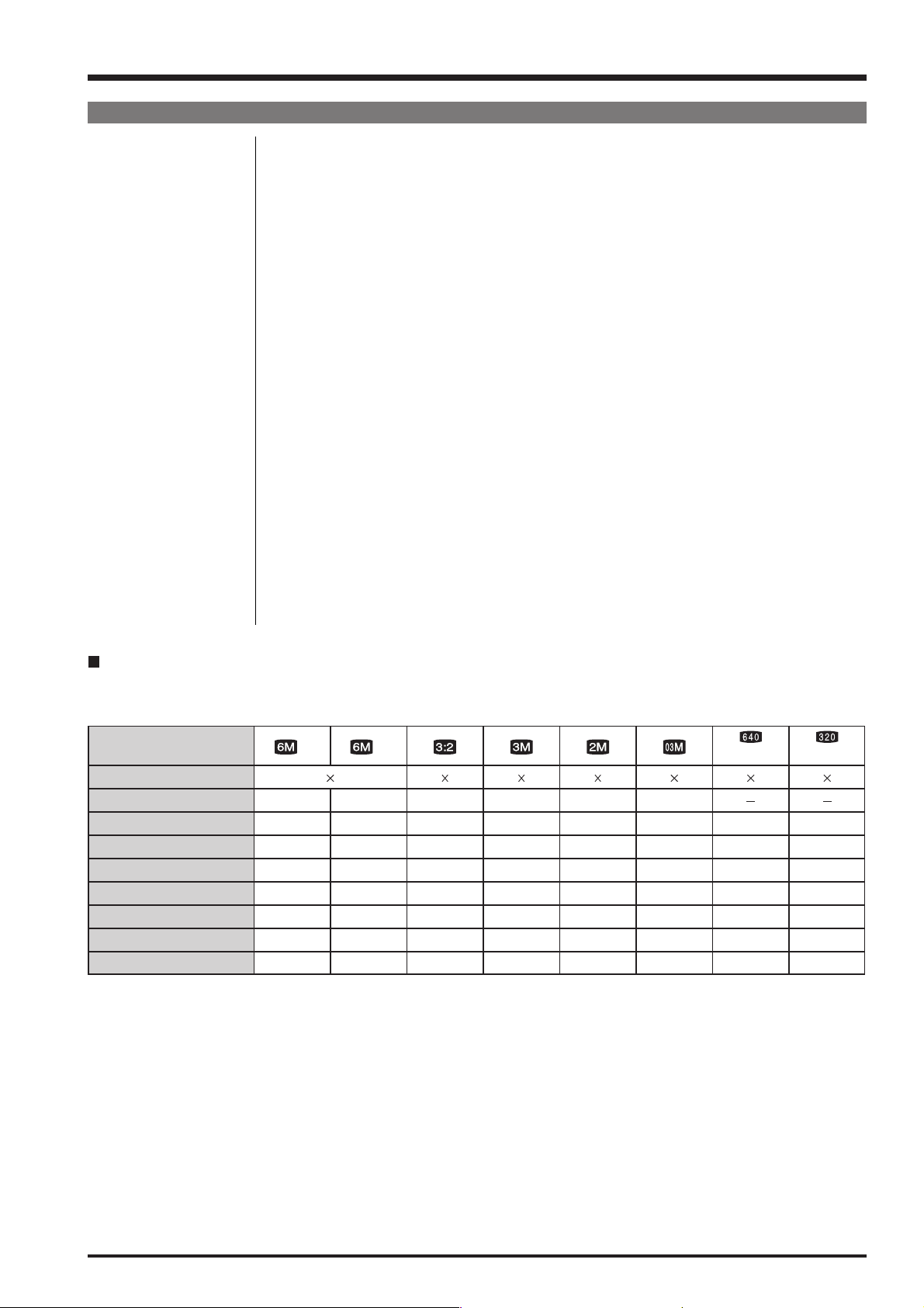
Standard number of available frames/recording time per xD-Picture Card
The number of available frames, recording time or file size varies slightly depending on the subjects photographed. Note also
that the divergence between standard number of frames and the actual number of frames is greater for
xD-Picture Cards with higher capacities.
Quality setting
Number of recorded pixels
Image data size
DPC-16 (16 MB)
DPC-32 (32 MB)
DPC-64 (64 MB)
DPC-128 (128 MB)
DPC-256/M256 (256 MB)
DPC-512/M512 (512 MB)
DPC-M1GB (1 GB)
If you shoot using the DPC-M256/M512/M1GB xD-Picture Card, movie recording time may be reduced if you repeatedly record and erase (frame erase) image files. In such a case, erase all frames or format the picture card before
use. Back up important frames (files) onto your PC or another media.
F
2848
3.0 MB
5
10
21
42
85
170
2136
1.5 MB
10
20
42
84
169
339
N
3024 2016 2048 1536 1600 1200
1.5 MB
10
20
42
84
169
339
780 KB
19
40
81
162
325
651
630 KB
25
50
101
204
409
818
640 480 640 480 320 240
130 KB
341 680 680 1305 1639 7995
122
247
497
997
1997
3993
(30 fps) (30 fps)
13 sec.
27 sec.
55 sec.
111 sec.
223 sec.
7.4 min.
14.9 min. 29.3 min.
26 sec.
54 sec.
109 sec.
219 sec.
7.3 min.
14.6 min.
9

1. General
FinePix F11 Service Manual
1-2. Explanation of Terms
EV: A number denotes Exposure Value. The EV is determined by the brightness of the
subject and sensitivity (speed) of the film or CCD. The number is larger for bright
subjects and smaller for dark subjects. As the brightness of the subject changes, a
digital camera maintains the amount of light hitting the CCD at a constant level by
adjusting the aperture and shutter speed.
When the amount of light striking the CCD doubles, the EV increases by 1. Likewise,
when the light is halved, the EV decreases by 1.
Frame rate (fps): The frame rate refers to the number of images (frames) that are photographed or played
back per second. For example, when 10 frames are continuously photographed in a 1second interval, the frame rate is expressed as 10 fps.
For reference, TV images are displayed at 30 fps (NTSC).
JPEG: Joint Photographic Experts Group
A file format used for compressing and saving color images. The higher the compression rate, the greater the loss of quality in the decompressed (restored) image.
Motion JPEG: A type of AVI (Audio Video Interleave) file format that handles images and sound as a
single file. Images in the file are recorded in JPEG format. Motion JPEG can be played
back by QuickTime 3.0 or later.
Smear: A phenomenon specific to CCDs whereby white streaks appear on the image when there
is a very strong light source, such as the sun or reflected sunlight, in the photography
screen.
WAVE: A standard format used on Windows systems for saving audio data. WAVE files have
the “.WAV” file extension and the data can be saved in either compressed or
uncompressed format. Uncompressed recording is used on this camera.
WAVE files can be played back on a personal computer using the following software:
Windows: MediaPlayer
Macintosh: QuickTime Player
* QuickTime 3.0 or later
White Balance: Whatever the kind of the light, the human eye adapts to it so that a white object still
looks white. On the other hand, devices such as digital cameras see a white subject as
white by first adjusting the color balance to suit the color of the ambient light around the
subject. This adjustment is called matching the white balance.
Exif Print: Exif Print Format is a newly revised digital camera file format that contains a variety of
shooting information for optimal printing.
10
FinePix F11 Service Manual
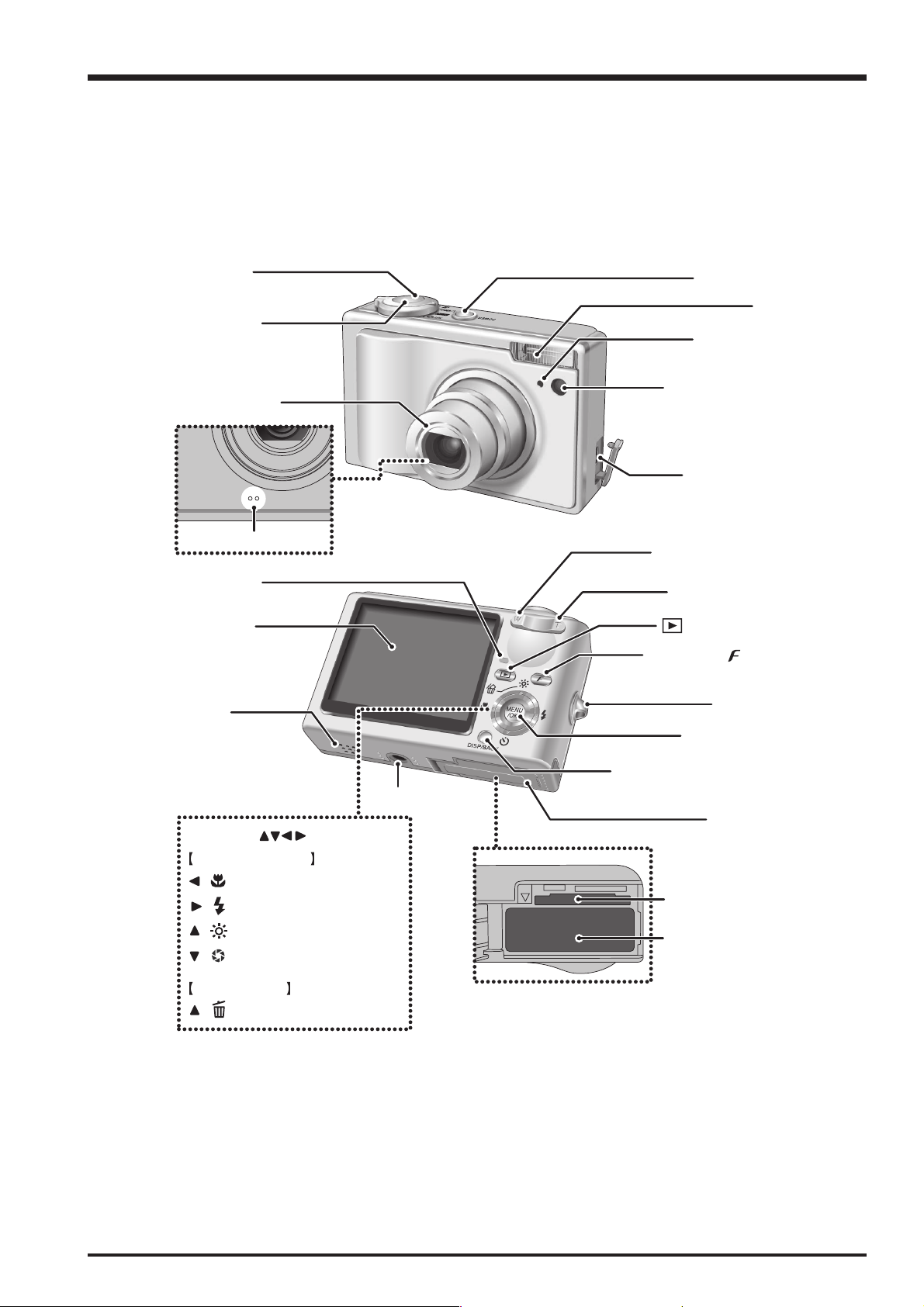
1-3. Names of External Components
1. General
Mode switch
Shutter button
Lens (lens cover)
Microphone
Indicator lamp
LCD monitor
Speaker
POWER button
Flash
Self-timer lamp
AF-assist illuminator
Terminal adapter
connection socket
W (Wide zoom) button
T (Tele zoom)button
(Playback) button
Photo mode ( ) button
Strap mount
MENU/OK button
4-direction ( ) button
Photography mode
/ Macro button
/ Flash button
/ Low light view button
/ Shutter speed / Aperture
button
Playback mode
/ Erase button
DISP (Display) / BACK button
Tripod mount
Battery cover
xD-Picture Card slot
Battery compartment
11

2. Disassembly
2. Disassembly
2-1. Names of internal Components
FinePix F11 Service Manual
R PANEL ASSY
OPE UNIT
LCD FRAME CONST
BATT HOLDER CONST
OPE GUM KEY
LCD CONST
MAIN PWB ASSY
LENS ASSY
12
AFLED CONST
ST CONST
SPEAKER ASSY
MIC ASSY
F PANEL ASSY

FinePix F11 Service Manual
2-2. Removing the R PANEL CONST
2. Disassembly
(1) Remove the 4 screws (ET #1 M1.7 x 3)
(2) Remove the 3 special screws (3-BTN M1.7 x 5.0). (Use
the special screwdriver (FZ00583-100).)
(3) Remove the REAR PANEL ASSY in the direction of the
arrow.
(4) Remove the JACK COVER.
(5) Disconnect the FPC in the direction of the arrow (at 2
points).
(6) Remove the R PANEL CONST in the direction of the
arrow.
3
1
2
5
1
6
[Notes on reassembly]
Fit the JACK COVER into the R PANEL CONST and check
that the protrusion on the JACK COVER is fitted into the
groove in the F PANEL CONST.
[Assembly]
Perform the disassembly procedure in reverse order.
4
13
2. Disassembly
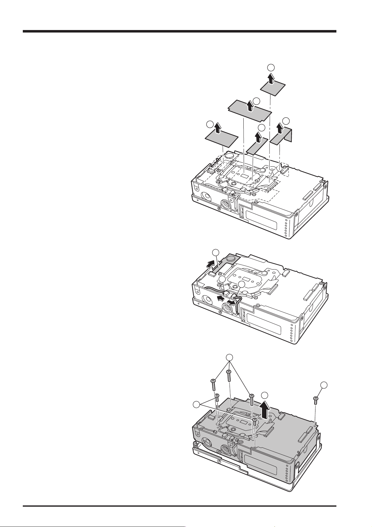
2-3. Removing the INNER BLOCK
FinePix F11 Service Manual
(1) Remove the EMI SHEET.
(2) Remove the BUSTERAID.
(3) Remove the K TAPE 2.
(4) Remove the TR TAPE CCD.
(5) Remove the K TAPE 1.
1
2
4
3
5
(6) Disconnect the FPC (ST CONST).
(7) Disconnect the wire harness (SPEAKER).
(8) Disconnect the wire harness (MIC).
(9) Remove the 3 screws (BT2 M1.7 x 4.0).
(10) Remove the 3 screws (BT2 M1.7 x 9.0B).
(11) Remove the INNER BLOCK in the direction of the
arrow.
[Notes]
Do not reuse the removed SHEET parts. Use new parts.
For K TAPE 1, cut a 9 x 35 mm piece of PIT-652S
polyimide tape (ZS00024-100).
For K TAPE 2, cut a 9 x 25 mm piece of PIT-652S
polyimide tape (ZS00024-100).
6
7
8
10
9
11
9
[Assembly]
Perform the disassembly procedure in reverse order.
14
FinePix F11 Service Manual
1
2
4
3
1
2
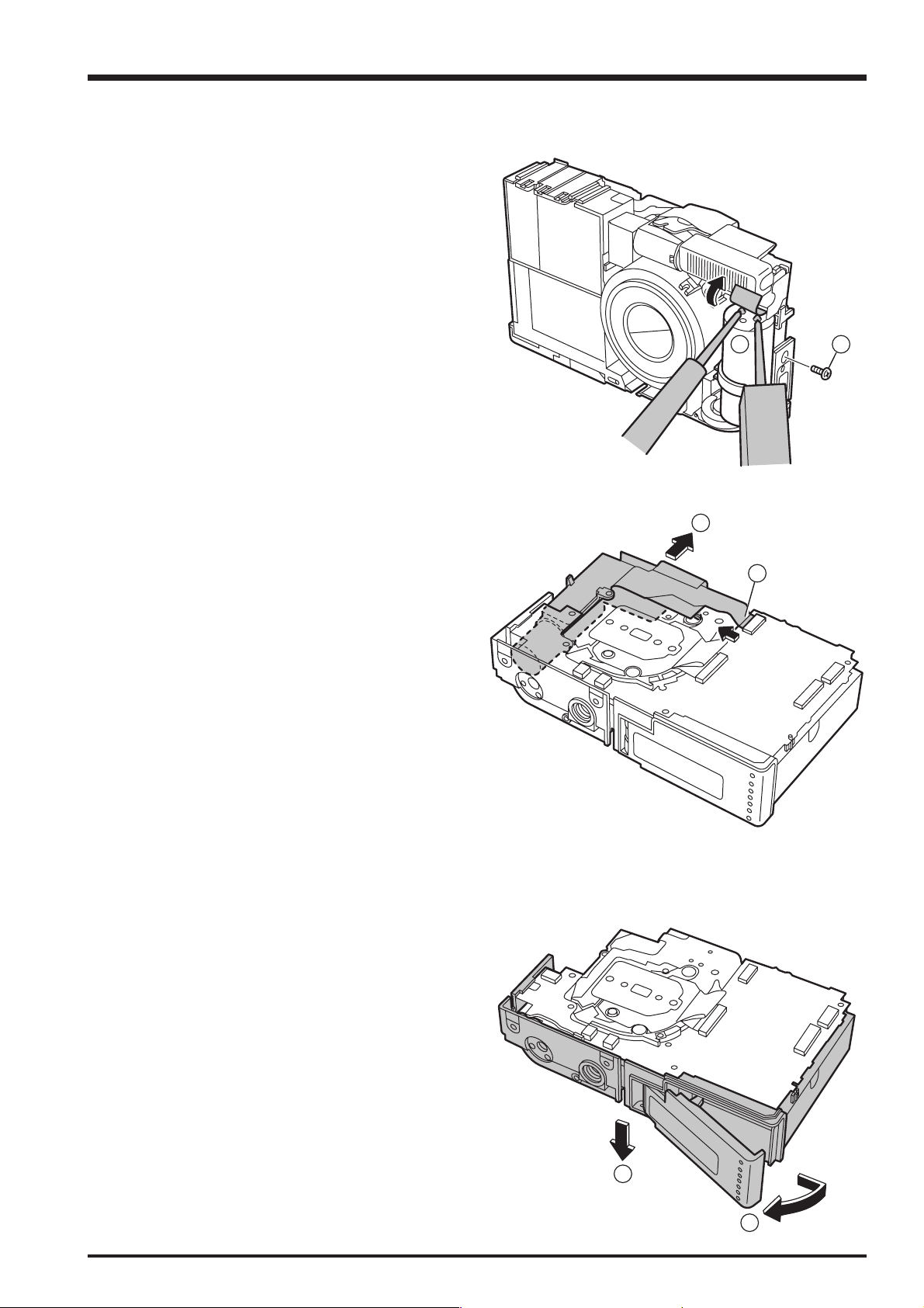
2-4. Removing the ST CONST
(1) Discharge the main capacitor for the flash.
(2) Remove the 1 screw (BT2 M1.7 x 4.0).
2. Disassembly
(3) Disconnect the FPC (ST CONST).
(4) Remove the ST CONST in the direction of the arrow.
[Notes on reassembly]
Check that the voltage in the main capacitor is fully
discharged.
[Assembly]
Perform the disassembly procedure in reverse order.
2-5. Removing the BATT HOLDER CONST
(1) Open the BATT LID.
(2) Remove the BATT HOLDER CONST in the direction of
the arrow.
[Assembly]
Perform the disassembly procedure in reverse order.
15

2. Disassembly
2-6. Removing the LENS ASSY
FinePix F11 Service Manual
(1) Disconnect the FPC (CCD).
(2) Disconnect the FPC (LENS).
(3) Remove the LENS ASSY in the direction of the arrow.
[Assembly]
Perform the disassembly procedure in reverse order.
2-7. Removing the LCD CONST
(1) Remove the 11 screws (BT2P 14 x 25N).
(2) Remove the LCD FRAME CONST in the direction of
the arrow.
3
1
1
2
1
(3) Remove the LCD CONST in the direction of the arrow.
[Assembly]
Perform the disassembly procedure in reverse order.
2
3
16

FinePix F11 Service Manual
2
3
4
1
2-8. Removing the OPE UNIT
(1) Set the Mode switch to the Movie mode position.
(2) Remove the 1 screw (BT2P 14 x 25N).
(3) Remove the FPC section of the OPE UNIT in the
direction of the arrow.
(4) Remove the dial section of the OPE UNIT in the
direction of the arrow.
[Assembly]
Perform the disassembly procedure in reverse order.
2. Disassembly
17

2. Disassembly
MEMO
FinePix F11 Service Manual
18

FinePix F11 Service Manual
3. Schematics
3. Schematics
3-1. Cautions
<Cautions when replacing parts>
• Do not reuse removed parts. Always use new parts.
• Note that the negative side of tantalum condensers is readily damaged by heat.
• Except for chemical condensers and tantalum condensers, voltage is not displayed on condensers with a voltage
resistance of 50V or less.
• Resistors not marked are 1/16W chip resistors.
•KΩ = 1000Ω, MΩ = 1000KΩ
• B characteristics of variable resistors and semi-fixed resistors are not displayed.
3-2. Basic Block Names and Functions
Part name Block name Function
LENS CONST CCD FPC BLOCK CCD Output
MAIN PWB ASSY CAMERA BLOCK CCD Output A/D Conversion (IC104)
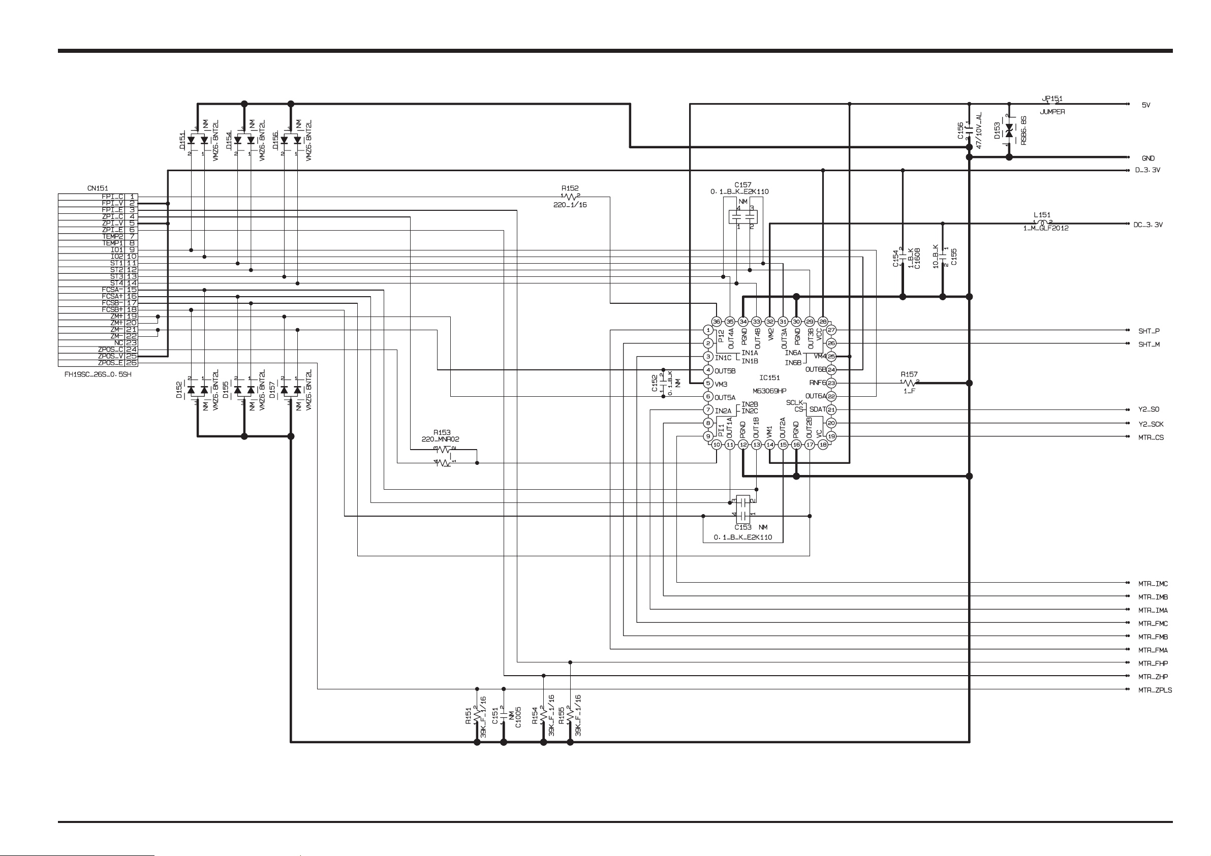
MOTOR BLOCK Shutter/iris/AF/zoom Drive (IC151)
AUDIO BLOCK Audio IN/OUT(IC601)
LCD BLOCK LCD Output CN, Back Light Control
DC/DC BLOCK Power Supply Generation (IC300),
PMAN BLOCK Power Control, LED Driver, Flash Charge Control (IC402)
VIDEO BLOCK Video Output (IC651)
FLASH CN BLOCK Connection with the FLASH UNIT
PROCESS BLOCK Image Signal Processing, USB Communications,
System Control (IC203)
ST UNIT FLASH BLOCK Flash Charge
19

3. Schematics
FinePix F11 Service Manual
3-3. Description of Main Block Functions
3-3-1. Technical Overview
The superb optics of the FUJINON lens collect light and precisely form the image on the 5th-generation Super CCD HR,
which works in tandem with our newly developed Real Photo Processor to perform highly sophisticated processing of the
image data at ultra-high speed. The result is an incredible degree of sensitivity with very low noise. Even at the maximum pixel
resolution with the highest sensitivity, the resulting photos are vividly natural and beautiful. FUJIFILM Real Photo Technology
is making it possible to take the photos as never before.
CCD signal processing/Camera circuit section
Analog signals output from the 1/1.7 type Super-CCD Honeycom V HR (IC951), with an effective pixel count of 6.3 mega-
pixels, undergo false color compensation processing, adaptive interpolation processing, amplification (AGC) and signal
mixing inside the CCD signal processing IC “BCS (IC104)” before being converted to 14-bit digital signals (A/D) and sent
to the signal processing LSI “YCS (IC203)”.
The vertical drive IC (IC103) for driving the CCD and the OFD voltage control IC (IC102) are in this block.
Motor Circuit Section
The signal processing LSI “YCS (IC203)” that has received various operating switch commands manages the motor drive
IC (IC151) and controls the AF, SHUTTER, ZOOM and IRIS motors.
Imaging and Signal Processing Section
Input data from the CCD
14-bit digital image data (corresponding to 1H) that has been output from the imaging section (CCD/Camera Block) is
sent to the signal processing LSI “YCS (IC203)”, converted to 32-bit (16-bit x 2) data by the [internal buffer] inside this
LSI, and the image data for one frame (2848 x 2136 pix) is stored temporarily in [SD-RAM]. It is also integrated in the
[AUTO operation section] using the 32-bit the signal processing LSI “YCS (IC203)” image data and sent to the BCS_IC
(IC104) to obtain the appropriate AE/AF/AWB.
Record processing to xD Card
Image data stored in SD-DRAM is sent one frame at a time to the internal [signal processing section] in the signal
processing LSI “YCS (IC203)”. In a process called unpacking, “32-bit to 12-bit conversion” and “pre-processing including
digital clamp, white balance and noise reduction processing, linear matrix processing, gamma correction and R/G/B 14-bit
to R/G/B 8-bit conversion” to “8-bit digital R/G/B signals to Y:Cb:Cr = 4:2:2 YC processing” are implemented in this [signal
processing section] and 8-bit Y/Cb/Cr image data are sent to the [internal buffer].
The “rearrangement of data in a format in which 8-bit Y/Cb/Cr signals are easily compressed” is done in the [internal
buffer] and after passing through the [JPEG operation block] to the [media controller], they are recorded on the xD card.
Reproduction of images from xD card
Compressed image data from the xD card is sent as 8-bit image data to the signal processing LSI “YCS (IC203)” then it is
sent to the [media control section], the [DMA unit] and the SD-DRAM and then it is sent to the [media controller], to the
[JPEG operation section] and to the [signal processing section].
In the [signal processing section], 8-bit Y/Cb/Cr signals are converted to 8-bit R/G/B signals and at the same time,
lettering display signals are weighted and passed through the [LCD controller to the LCD unit and displayed.
Image capture system adjustment data are stored in the Flash ROM.
LCD Unit
Digital signals sent from the signal processing LSI “YCS (IC203)” are sent directly to the LCD.
Power Supply Section
Power supply circuits constructed in the core of the DC IC (IC300) create the following power supplies, which are
supplied to each block.
D3.3V [IC151 (MOTOR BLOCK), IC203 (YCS), IC352 (CHG), IC402 (IPS), LCD (CN501), KEY BLOCK
(CN801), MEDIA BLOCK (CN251)]
5V [IC103 (V_Drv), IC151 (MOTOR BLOCK), IC402 (IPS), IC501 (LCD BLOCK)]
-8V [IC951 (CCD), IC103 (V_Drv)]
15V [IC103 (V_Drv), IC102 (OFD_Drv)]
CAM3.3V [IC103 (V_Drv), IC104 (BCS)]
1.0V [IC203 (YCS)]
2.5V [IC203 (YCS)]
DC_3.3V [IC151 (MOTOR BLOCK), IC601 (AUDIO BLOCK), IC402 (IPS)]
AD_3.3V [IC651 (VIDEO BLOCK), KEY BLOCK (CN801), IC203 (YCS)]
LCD_12V [LCD (CN501)]
20
FinePix F11 Service Manual
2
2
3. Schematics
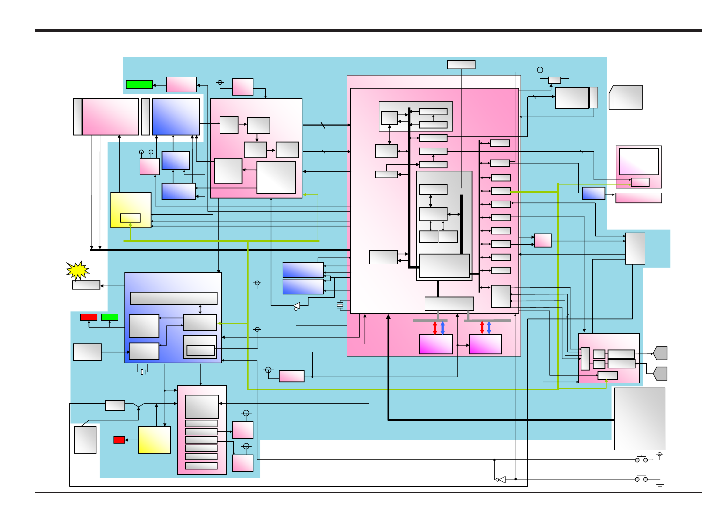
3-4. Block Diagram
3
LENS Barrier
Zoom position
Zoom HP
S
EX-
BRT
E
L
R_D
TTAB
pukcaB
.TTAB
021-PN
MOOZx
spetS01 SIRI
Focus HP
IC151
L
G_DE
MAIN PWB BLOCK
T
C-AH
IC951
SAIB
SLUP TH
SC_RT
SPI
CI egrahC
vrD DEL
DC
D5983SM
hcni7.1/
xip nollim3.6
Ø
GR/DFO
F5212MJN
RG
,LESV_DC
CNO_MA
2 * E
30203NA
RTC HSAL
IC300
e
V
.vrD V
4712DM
L
SNEL
C.tno
P
ESUF
DE
AF LED
elbairaV ELET/EDIW
5
1
se
slu
hc6
LTC
SI0_2
IC402
4
X10
O.LPF
V5
V
DC
C
woPer
.vrD rotoM
PH96036M
DEL
REVIRD
×3
CTR
IC352
GHC ttaB & REMIT FLES
1
tceleS
C
S
F
suco
M
F
PWCTL
ZH
k867.23 552-CF
84226M
TJGA
E_D
OF RV
5
V
F08811K
CCDIN
sl
ireS
se
R
GE
V5.
3
SCB 4
I6
01
C
epO V3
.3
SDC
DA
999DA
noita
r
C
AD_DCC:
1]0
[T
3
tib41
H
Ø
latigiD
niaG
rG
ya
,DVAA,DHKCDA
edoC
H
virD.re
s
e
V
luP
3 * esluP mooZ,3 * esluP
STB_SY
GT
orP(
g
I
CCDCLK(36MHz)
LES KLCDCC
I
B
)elbamar
S
1_0I
D
r
otareneG kcolC
VFH3703UB 102C
r
otareneG kcolC
VFH2703UB 202C
TESER_SCB,SC_SC
TESER_RDV
NO_DE
L_FA
ys tcete
mets
zHM573.42/545.42
LES LAP/TN
N
O_KLCV
zHM8
4
NO_KLCDCC
L
’XTAL
XC 102F101-
LTC
P
no rewo
3
_0IS
V3.3D
I
X
zHM00.84
CC_BRTS,TCA_SPI,SC_SP
V_TABWS_RWP
teseR
CD
C
C
3.3V_ON
/CD
hc6
V0.1
V3.3
5
V
21DCL
kcolB CD/
I CD
.C
V5.2
seireS
GER
V5.2
A
V51DC
V8-DC
V
reS
sei
GER
V3.3
0
.
V
1
ER
CI TES
V9.
0
NO_DCC
,V3.3_D
PIS
SCY
GBMAB92K8T 302CI
noitarepO V3.3 eroiF
CFBI
OTUA
R
CCE
CYPRO
NEG
C
J
J
GEP
GEP
TESER
OTUA
FIDCC
FIDCC
AIDE
AIDE
M
M
CDFT
CDFT
E
E
DCN
DCN
GUBEDF/I
GUBEDF/I
eroC UPC
eroC UPC
h
-I cache 16k
-Ie
cac
k8
D
D
O
O
I
I
/
/
64
S
MARD
TR
AU
RV
E
eroC UPC 94XT
eroC UPC 94XT
-Dehcac
8
k
Peripheral BUS 96MHz
Peripheral BUS 120MHz
.tnoC SUB
.tnoC SUB
CMARDS
CMARDS
CAM
CAM
reffuB
reffuB
SUB A2
LF
46x bM652
TDW
OIS
OISC
0.2BSU
TFM
TFM
UCI
UCI
DA
AD
C
C
OPTR
OPTR
CKLC
CKLC
S
I
x
3x SUB B
HSA
61x tibM23
B
VI EDNO
PLAY_SW
NIDAA
O
ADATU
V3.3D
WS
NO_ADM
DxC ard
SUB
DRAC
W
S_RD
L
tolS
)NIP02(
DR_SW
,
KLC_DCL,]0:7[TADDCL
V_
DCL,DH_DC
SC_DCL,D
DxC ard
lenaP DCL
RVE_LB_DCL
3
S
_OI
DEL LB
revirD
PEE
_O
V
oedi
revirD
IC651
TED_VA
KLCMA
KLCFA
KLCBA,
O_SBV
T
U
O_UATU
h
cni5.2
1.0
M5
LTC
p41
ITLUM
DC IN 5V
)OISAC(
lexiP
3x DEL LB
eldarC
to
N
detroppuS
CI OIDUA
R
EP
EKA
C
IM
A
O
IS_3
NK4087UB
S
I
A
D
D
A
SC_U
ETUM_UA
LTC
IC601
S
PMA_PS
PMA_CIM
YEK
2S/1S
)
(WS ESA
EDIW/ELET
WS U/D/L/R
)s
op4(WS E
OK WS F/KCAB/
M
ELER
DO
OPWS REW
YALP WS
21
3. Schematics
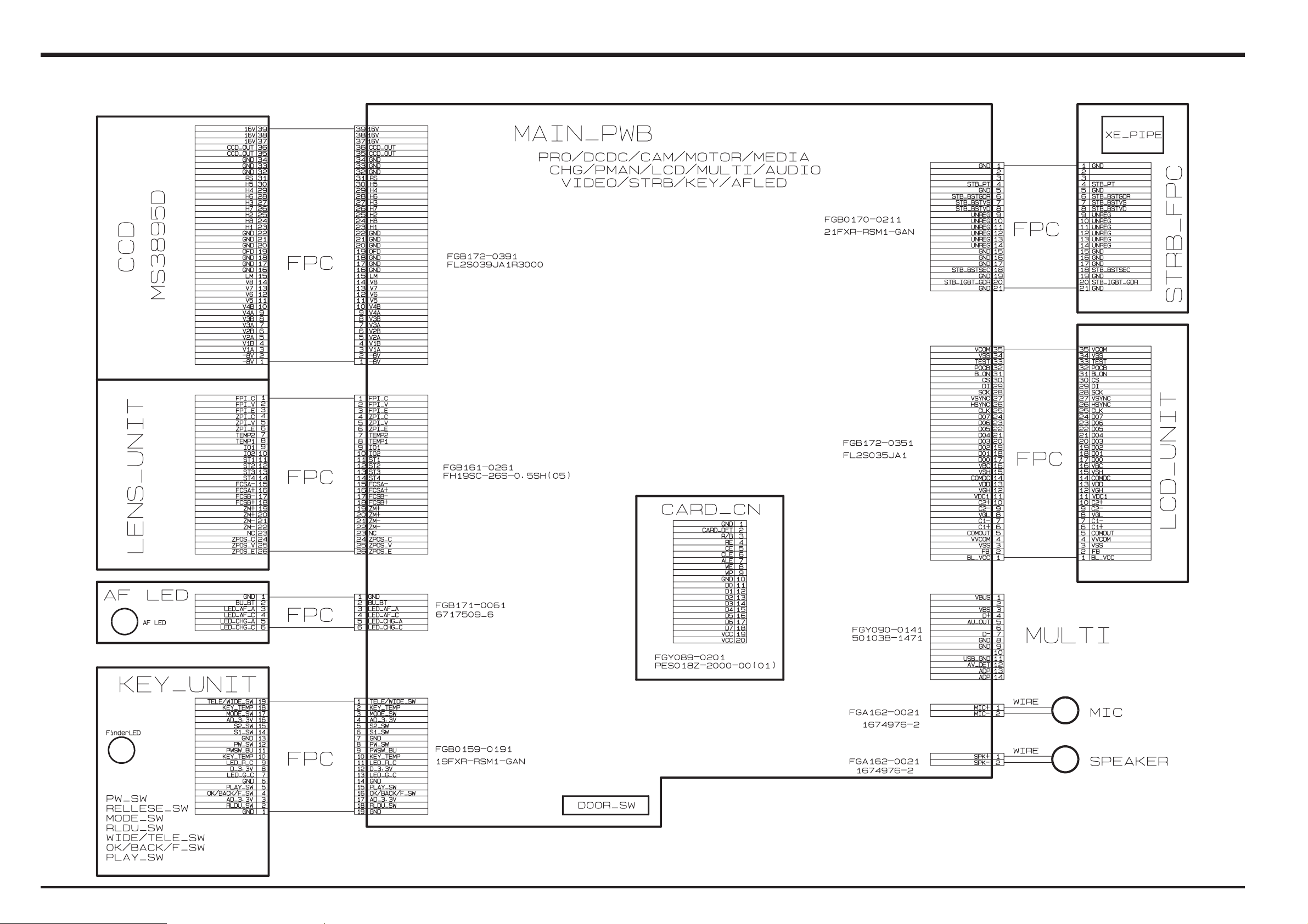
3-5. Overall connection Diagram
FinePix F11 Service Manual
22
FinePix F11 Service Manual
3. Schematics
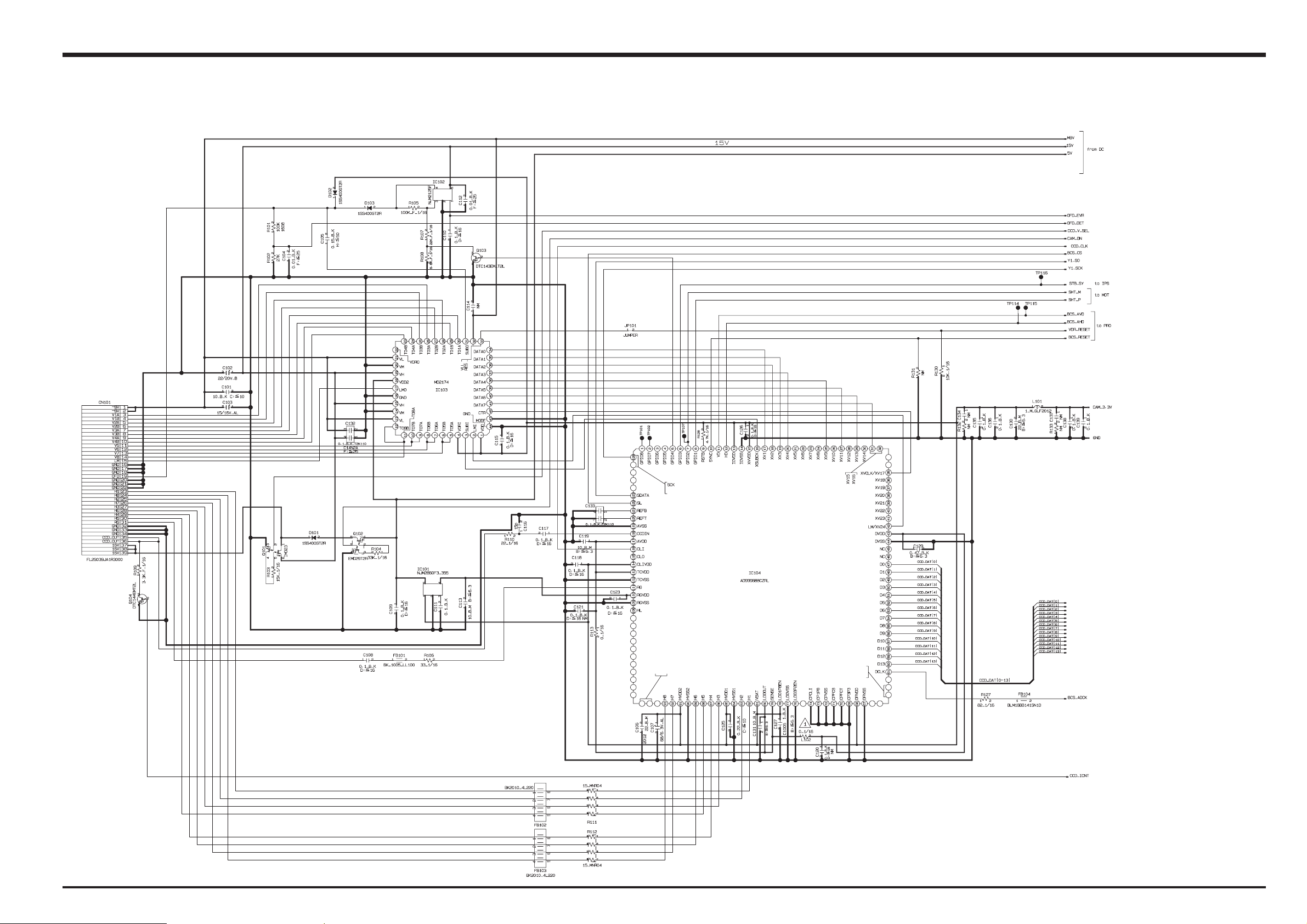
3-6. Circuit Diagrams
3-6-1. CAMERA BLOCK
23

3. Schematics
3-6-2. DC/DC BLOCK
FinePix F11 Service Manual
24
FinePix F11 Service Manual
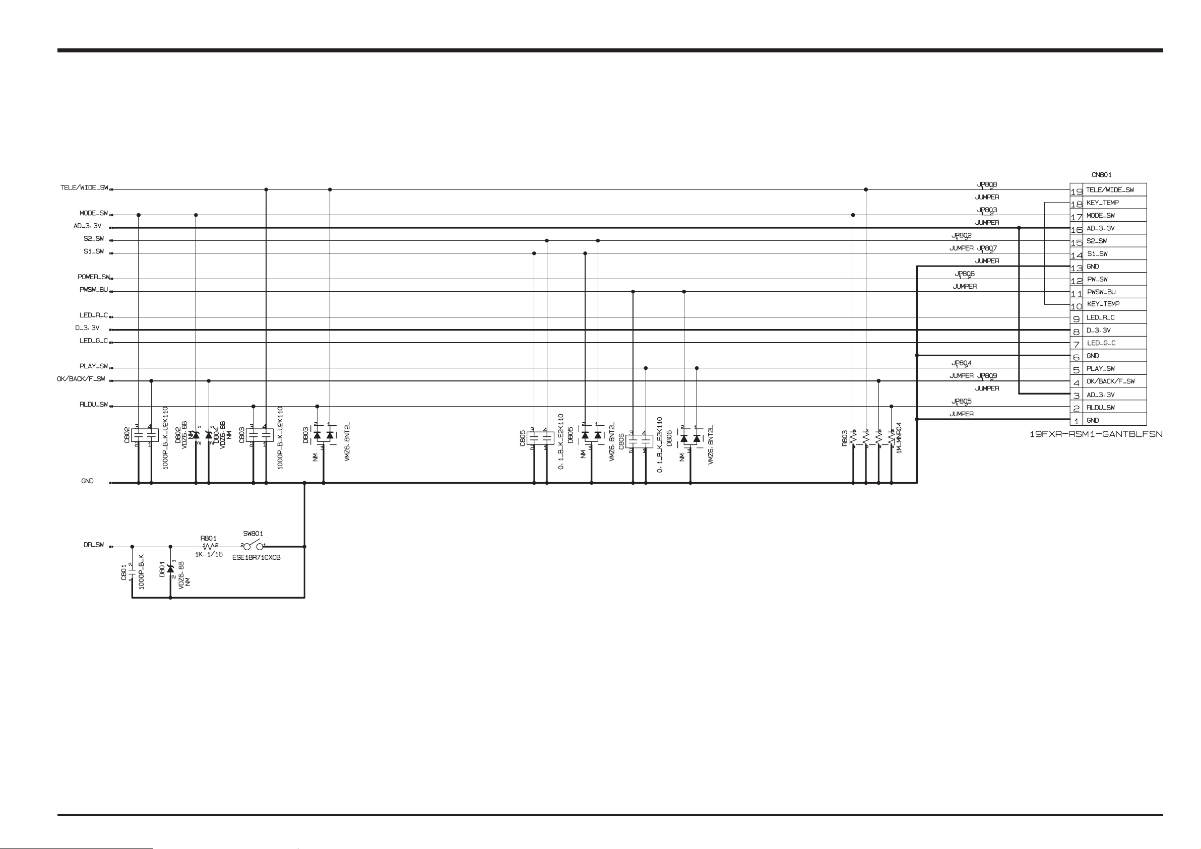
3. Schematics
3-6-3. KEY BLOCK
25
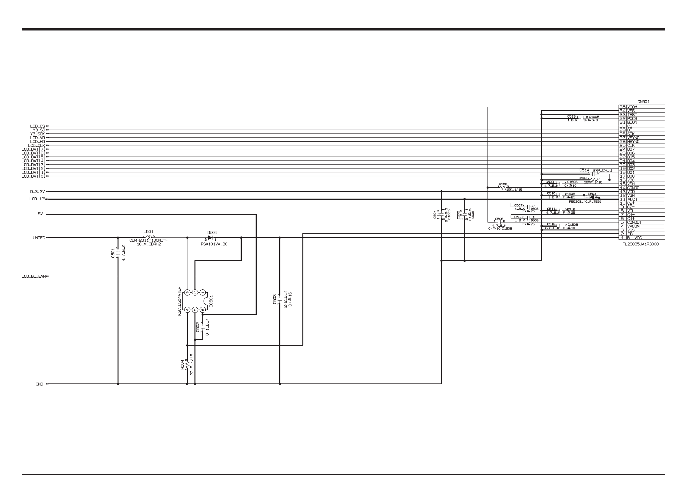
3. Schematics
3-6-4. LCD BLOCK
FinePix F11 Service Manual
26
FinePix F11 Service Manual
3. Schematics
3-6-5. MOTOR BLOCK
27
 Loading...