

FUJIFILM FinePix A360, FinePix А370 SERVICE MANUAL

DIGITAL CAMERA
FinePix A360
SERVICE MANUAL
EU/EG/US-Model
WARNING
THE COMPONENTS IDENTIFIED WITH THE MARK “ ” ON THE SCHEMATIC
DIAGRAM AND IN THE PARTS LIST ARE CRITICAL FOR SAFETY.
PLEASE REPLACE ONLY WITH THE COMPONENTS SPECIFIED ON THE SCHEMATIC
DIAGRAM AND IN THE PARTS LIST.
IF YOU USE PARTS NOT SPECIFIED, IT MAY RESULT IN A FIRE AND AN
ELECTRICAL SHOCK.
FUJI PHOTO FILM CO., LTD.
Ref.No.: ZM00598-103
Printed in Japan 2006.03

FinePix A360 Service Manual
SAFETY CHECK-OUT
After correcting the original problem, perform the following
safety check before return the product to the customer.
1. Check the area of your repair for unsoldered or poorly
soldered connections. Check the entire board surface
for solder splasher and bridges.
2. Check the interboard wiring to ensure that no wires are
“pinched” or contact high-wattage resistors.
3. Look for unauthorized replacement parts, particularly
transistors, that were installed during a previous repair.
Point them out to the customer and recommend their
replacement.
4. Look for parts which, though functioning, show obvious
signs of deterioration. Point them out to the customer
and recommend their replacement.
5. Check the B + voltage to see it is at the values
specified.
6. Make leakage - current measurements to determine
that exposed parts are acceptably insulated from the
supply circuit before returning the product to the
customer.
7. CAUTION: FOR CONTINUED
PROTECTION AGAINST FIRE
HAZARD, REPLACE ONLY WITH
SAME TYPE 2.5 AMPERES 125V
FUSE.
2.5A 125V
2.5A 125V
8. WARNING:
RISK OF FIREREPLACE FUSE
AS MARKED
ATTENTION: AFIN D'ASSURER
UNE PROTECTION
PERMANENTE CONTRE LES
RISQUES D'INCENDIE,
REMPLACER UNIQUEMENT
PAR UN FUSIBLE DE MEME,
TYPE 2.5 AMPERES, 125 VOLTS.
TO REDUCE THE ELECTRIC
SHOCK, BE CAREFUL TO
TOUCH THE PARTS.
WARNING!
HIGH VOLTAGE
2

FinePix A360 Service Manual
CONTENTS
CONTENTS
1. General ........................................................... 4
1-1. Product specification .............................................. 4
1-2. Explanation of Terms .............................................. 7
1-3. Names of External Components ............................ 8
2. Disassembly ................................................... 9
2-1. Names of internal Components ..............................9
2-2. Removing the rear cover ...................................... 10
2-3. Removing the shutter button unit ......................... 11
2-4. Removing the MB_PCB unit ................................. 11
2-5. Removing the lens unit .........................................13
2-6. Removing the CCD .............................................. 14
2-7. Removing the battery box .................................... 14
2-8. Removing the screw holder .................................. 16
2-9. Removing the flash unit ........................................16
2-10. Removing the AV PCB ......................................... 16
2-11. Sheet component installation location
specifications ........................................................ 17
3. Schematics ................................................... 18
3-1. Cautions ............................................................... 18
3-2. Basic Block Names and Functions .......................18
3-3. Description of Main Block Functions .................... 19
3-3-1. Technical Overview ................................. 19
3-3-2. MAIN Board Block Functions .................. 19
3-4. Block Diagram ...................................................... 20
3-5. Over all connection Diagram ................................ 21
3-6. Circuit Diagrams ...................................................22
3-6-1. AV BOARD BLOCK ................................ 22
3-6-2. SHUTTER BOARD BLOCK .................... 23
3-6-3. RTC BLOCK ........................................... 23
3-6-4. STROBE BOARD BLOCK ......................24
3-6-5. SDRAM & NOR FLASH BLOCK ............. 25
3-6-6. KEY BLOCK ........................................... 26
3-6-7. LENS DRIVER BLOCK ........................... 27
3-6-8. CCD BLOCK ........................................... 28
3-6-9. POWER INPUT/OVP BLOCK ................. 29
3-6-10. AUDIO/TV OUT BLOCK ......................... 30
3-6-11. USB/LED BLOCK ................................... 31
3-6-12. XD-CARD BLOCK .................................. 32
3-6-13. DSP BLOCK ........................................... 33
3-6-14. POWER BLOCK ..................................... 34
3-6-15. LCD BLOCK ........................................... 35
3-6-16. AFE BLOCK ............................................ 36
3-7. Mounted Parts Diagrams ...................................... 37
3-7-1. FLASH BOARD ASSY ............................ 37
3-7-2. MAIN BOARD ASSY............................... 38
3-7-3. AV BOARD ASSY ................................... 40
3-7-4. SHUTTER BOARD ASSY ...................... 40
3-7-5. CCD BOARD ASSY ................................ 40
4. Adjustment.................................................... 41
4-1. Important adjustment tests & order when
replacing major parts ............................................ 41
4-2. Measuring equipments used ................................ 41
4-3. Jig list ................................................................... 41
4-4. Preparation of Adjustment Software and
Firmware .............................................................. 42
4-4-1. Various downloading software
decompressions, preservation methods,
and notes ................................................42
4-4-2. Various downloading Firmware
decompressions, preservation methods,
and notes ................................................43
4-4-3. Explanation of "_752EXT.M" ................... 44
4-5. Firmware Version update ..................................... 44
4-6. Self test & End voltage adjustment ...................... 45
4-7. CCD defect correction .......................................... 46
4-8. Shutter adjustment ............................................... 47
4-9. Lens test & Zoom set ........................................... 47
4-10. ISO sensitivity adjustment ....................................48
4-11. EFA Adjustment (AF Adjustment) .........................48
4-12. Color Correction ................................................... 49
4-13. Flash Adjustment .................................................. 50
4-14. USB_ID Input (Set Serial NO.) ............................. 51
4-15. Language setting .................................................. 52
5. Inspection ..................................................... 53
5-1. Required Measuring Equipment ...........................53
5-2. Connection of Measuring Equipment ................... 53
5-3. Inspection and Factory Settings ........................... 53
6. Parts List....................................................... 56
6-1. Packing and Accessories ..................................... 56
6-1-1. EU-model ................................................ 56
6-1-2. EG-model ................................................ 57
6-1-3. US-model ................................................ 58
6-1-4. EU-model (WEEE) .................................. 59
6-1-5. EG-model (WEEE) .................................. 60
6-2. Cabi Front block ................................................... 61
6-3. Cabi Rear block ....................................................62
6-4. Electrical parts ......................................................63
7. Appendix....................................................... 64
7-1. List of Related Technical Updates Issued ............ 64
3

1. General FinePix A360 Service Manual
1. General
1-1. Product specification
System
Model Digital camera FinePix A360
Effective pixels 4.1 million pixels
CCD sensor 1/2.5 inch square pixel CCD
Number of total pixels: 4.23 million pixels
Storage media xD-Picture Card (16/32/64/128/256/512 MB/1 GB)
File format Still image:JPEG (Exif ver. 2.2)
* Design rule for Camera File System compliant DPOF-compatible
Movie: AVI format, Motion JPEG
Number of recorded pixels
Lens Fujinon 3
Focal length f=5.8 mm to 17.4 mm
Digital zoom Approx. 3.6
Focus TTL contrast-type, Auto focus
Focal range Normal: approx. 60 cm (2.0 ft.) to infinity
Shutter speed 2 sec. to 1/2000 sec. (depend on Exposure mode)
Aperture F2.8/F4.7 (automatically selected)
Sensitivity AUTO (Equivalent to ISO 64 to 400, depending on conditions)
Photometry Multi point TTL metering
Exposure control Program AE
Exposure compensation -2.1 EV to +1.5 EV in 0.3 EV-step increments (in Manual mode)
White balance Auto (
Viewfinder Real image optical Approx. 75% coverage
LCD monitor 1.7 inches, Aspect ratio: 4:3; 115,000 pixels Amorphous silicon TFT, Approx. 90% coverage
Flash type Auto flash
Self-timer 2 sec./10 sec.
Continuous shooting Number of available frames in Continuous shooting mode
Shooting functions Best framing, Frame No. memory
Playback functions Trimming, Automatic playback, Multi-frame playback
Other functions PictBridge, Exif Print, Language (English, Francais, Deutsch,
Still image:2304 × 1728 pixels/2304 × 1536 pixels/1600 × 1200 pixels/
1280
×
960 pixels/640 × 480 pixels ( / / / / )
Movie: 320 × 240 pixels (15 frames per second with monaural sound)
160
×
120 pixels (15 frames per second with monaural sound)
×
optical zoom lens, F2.8-F4.7
(Equivalent to 35 mm to 105 mm on a 35 mm camera)
×
(3× optical zoom lens is used together: Max. zoom scale: approx. 10.8× )
Macro: approx. 6 cm (2.4 in.) to 80 cm (2.6 ft.) (wide-angle)
, , , , )
Manual modes, 7 positions can be selected (
Effective range: Wide-angle: approx. 60 cm-3.5 m (2.0 ft.-11.5 ft.)
Telephoto: approx. 60 cm-3 m (2.0 ft.-9.8 ft.)
Macro: approx. 30 cm-80 cm (1.0 ft.-2.6 ft.)
Flash modes: Auto, Red-Eye Reduction, Forced Flash, Suppressed Flash, Slow Synchro,
Red-Eye Reduction + Slow Synchro
F 3 frames/ N 4 frames/ 4 frames/ 5 frames/ 6 frames/ 18 frames/
(Max. 1.5 frames/sec.)
World time (Time difference), Discharge batteries
)
, Italiano, , ),
4

Input/Output Terminals
A/V OUT 2.5 mm dia. jack
(Audio/Visual output) socket
USB (mini-B) socket For file transfer to a PC
DC input socket Socket for specified AC power adapter AC-3VX (sold separately)
Power Supply and Others
Power supply Use one of the following:
• 2
×
AA-size alkaline batteries
• 2
×
AA-size Ni-MH (Nickel-Metal Hydride) batteries (sold separately)
• AC power adapter AC-3VX (sold separately)
Conditions for use Temperature: 0
Guide to the number
of available frames
for battery operation
Alkaline batteries
Ni-MH batteries 2300 mAh
According to the CIPA (Camera & Imaging Products Association) standard procedure for
measuring digital still camera battery consumption (extract):
When using alkaline batteries, use the battery supplied with the camera. You can use Ni-MH
batteries also. The storage media should be xD-Picture Card.
Pictures should be taken at a temperature of +23
the optical zoom moved from full wide-angle to full telephoto (or vice-versa) and back again to
its original position every 30 seconds, the flash used at full power every second shot and the
camera turned off and then on again once every 10 shots.
• Note: Because the number of available shots varies depending on the capacity of alkaline
The number of available shots will also decline at low temperatures.
Camera dimensions 90.0 mm
(W/H/D) (not including accessories and attachments)
Camera mass (weight) Approx. 132 g/4.7 oz.
(not including accessories, battery and xD-Picture Card)
Weight for photography Approx. 180 g/6.3 oz. (including battery and xD-Picture Card)
Accessories included z LR6 AA-size Alkaline Batteries (2)
z xD-Picture Card (1)
z Strap (1)
z A/V cable (1)
z USB cable (mini-B) (1)
z CD-ROM (1) Software for FinePix BX
z Owner’s Manual (1)
o
C to +40oC (+32oF to +104oF); 80% humidity or less (no condensation)
Battery Type Number of frames
Approx. 100 frames
Approx. 290 frames
o
C (+73oF), with the LCD monitor turned on,
batteries or the level of charge in Ni-MH batteries, the figures shown here for the
number of available shots using batteries are not guaranteed.
×
60.0 mm × 30.3 mm/3.5 in. × 2.4 in. × 1.2 in.
1. GeneralFinePix A360 Service Manual
5

1. General FinePix A360 Service Manual
Power Supply and Others
Optional accessories z xD-Picture Card
DPC-16 (16 MB)/DPC-32 (32 MB)/DPC-64 (64 MB)/DPC-128 (128 MB)/
DPC-256 (256 MB)/DPC-512 (512 MB)/DPC-M1GB (1 GB)
z AC Power Adapter AC-3VX z Fujifilm Rechargeable Battery 2HR-3UF
z Fujifilm Battery Charger with Battery BK-NH/BK-NH2 (With Euro type or UK type plug)
z Soft Case SC-FXA02
z Image Memory Card Reader DPC-R1
• Compatible with Windows 98/98 SE, Windows Me, Windows 2000 Professional,
Windows XP or iMac, Mac OS 8.6 to 9.2.2, Mac OS X (10.1.2 to 10.2.2) and models
that support USB as standard.
• Compatible with xD-Picture Card of 16 MB to 512 MB, and SmartMedia of 3.3 V, 4 MB
to 128 MB.
z PC Card Adapter DPC-AD
• Compatible with xD-Picture Card of 16 MB to 512 MB, and SmartMedia of 3.3 V, 2 MB
to 128 MB.
z CompactFlash Card Adapter DPC-CF
• Windows 95/98/98 SE/Me/2000 Professional/XP
• Mac OS 8.6 to 9.2/X (10.1.2 to 10.1.5)
z xD-Picture Card USB Drive DPC-UD1
• Compatible with xD-Picture Card of 16 MB to 512 MB
• Windows 98/98 SE/Me/2000 Professional/XP
• Mac OS 9.0 to 9.2.2/X (10.0.4 to 10.2.6)
Standard number of available frames/recording time per xD-Picture Card
The number of available
that the difference between standard number of
with higher capacities.
Quality Setting
Number of recorded pixels
Image Data Size
DPC-16 (16 MB)
DPC-32 (32 MB)
DPC-64 (64 MB)
DPC-128 (128 MB)
DPC-256 (256 MB)
DPC-512 (512 MB)
DPC-M1GB (1 GB)
, recording time or file size varies slightly depending on the subjects photographed. Note also
frames
and the actual number of
890 KB
18
36
72
144
289
578
1162
630 KB
25
50
101
204
409
818
1639
470 KB
33
68
137
275
550
1101
2205
F
2304
2.0 MB
7
15
32
64
129
259
519
frames
N Movie
1728
2304 1536 1600 1200 1280 960
990 KB
15
31
64
128
257
515
1031
frames
640 480
130 KB
is greater for xD-Picture Cards
Movie
160 120
260 sec.
8.6 min.
17.3 min.
34.6 min.
69.3 min.
138.6 min.
277.3 min.
122
247
497
997
1997
3993
7995
320 240
65 sec.
130 sec.
260 sec.
8.6 min.
17.3 min.
34.6 min.
69.3 min.
6

1. GeneralFinePix A360 Service Manual
1-2. Explanation of Terms
Deactivated batteries: Leaving an Ni-MH battery unused in storage for a long period may cause a rise in the level of
substances that inhibit current flow inside the battery and result in a dormant battery. A battery
in this state is referred to as deactivated.
Because current flow is inhibited in a deactivated Ni-MH battery, the battery’s original level of
performance cannot be achieved.
DPOF: Digital Print Order Format
DPOF is a format used for recording information on a storage media (image memory card,
etc.) that allows you to specify which of the frames shot using a digital camera are to be
printed and how many prints are made of each image.
EV: A number denotes Exposure Value. The EV is determined by the brightness of the subject
and sensitivity (speed) of the film or CCD. The number is larger for bright subjects and
smaller for dark subjects. As the brightness of the subject changes, a digital camera maintains the amount of light hitting the CCD at a constant level by adjusting the aperture and
shutter speed.
When the amount of light striking the CCD doubles, the EV increases by 1. Likewise, when
the light is halved, the EV decreases by 1.
Frame rate (fps): The frame rate refers to the number of images (frames) that are photographed or played back
per second. For example, when 15 frames are continuously photographed in a 1-second
interval, the frame rate is expressed as 15 fps.
For reference, TV images are displayed at 30 fps (NTSC).
JPEG: Joint Photographic Experts Group
A file format used for compressing and saving color images. The higher the compression
rate, the greater the loss of quality in the decompressed (restored) image.
Memory effect: If an Ni-MH battery is repeatedly charged without first being fully discharged, its performance
may drop below its original level. This is referred to as the “memory effect”.
Motion JPEG: A type of AVI (Audio Video Interleave) file format that handles images and sound as a single
file. Images in the file are recorded in JPEG format. Motion JPEG can be played back by
QuickTime 3.0 or later.
PC Card: A generic term for cards that meet the PC Card Standard.
PC Card Standard: A standard for PC cards determined by the PCMCIA.
PCMCIA: Personal Computer Memory Card International Association (US).
WAVE: A standard format used on Windows systems for saving audio data. WAVE files have the
“.WAV” file extension and the data can be saved in either compressed or uncompressed
format. Uncompressed recording is used on this camera.
WAVE files can be played back on a personal computer using the following software:
Windows: MediaPlayer
Macintosh: QuickTime Player
* QuickTime 3.0 or later
White Balance: Whatever the kind of the light, the human eye adapts to it so that a white object still looks
white. On the other hand, devices such as digital cameras see a white subject as white by
first adjusting the color balance to suit the color of the ambient light around the subject. This
adjustment is called matching the white balance.
Exif Print: Exif Print Format is a newly revised digital camera file format that contains a variety of shoot-
ing information for optimal printing.
7
1. General FinePix A360 Service Manual
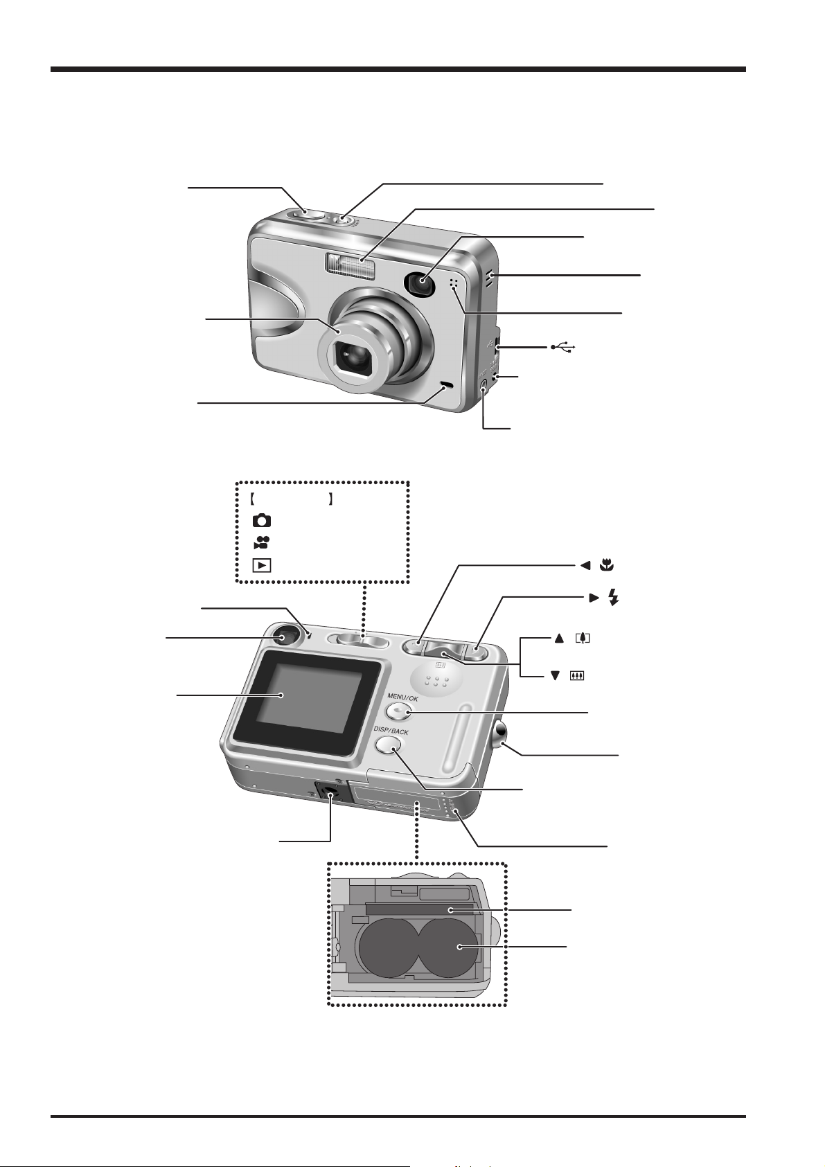
1-3. Names of External Components
Shutter button
Lens (lens cover)
Self-timer lamp
Mode switch
Photography mode
Movie mode
Playback mode
POWER button
Flash
Viewfinder window
Speaker
Microphone
USB socket (mini-B)
DC IN 3V (power input) socket
A/V OUT (Audio / Visual output)
socket
/ Macro button
Viewfinder lamp
Viewfinder
LCD monitor
Tripod mount
/ Flash button
/ Tele zoom switch
/ Wide zoom switch
MENU/OK button
Strap mount
DISP (Display) / BACK button
Battery cover
xD-Picture Card slot
Battery compartment
8
FinePix A360 Service Manual
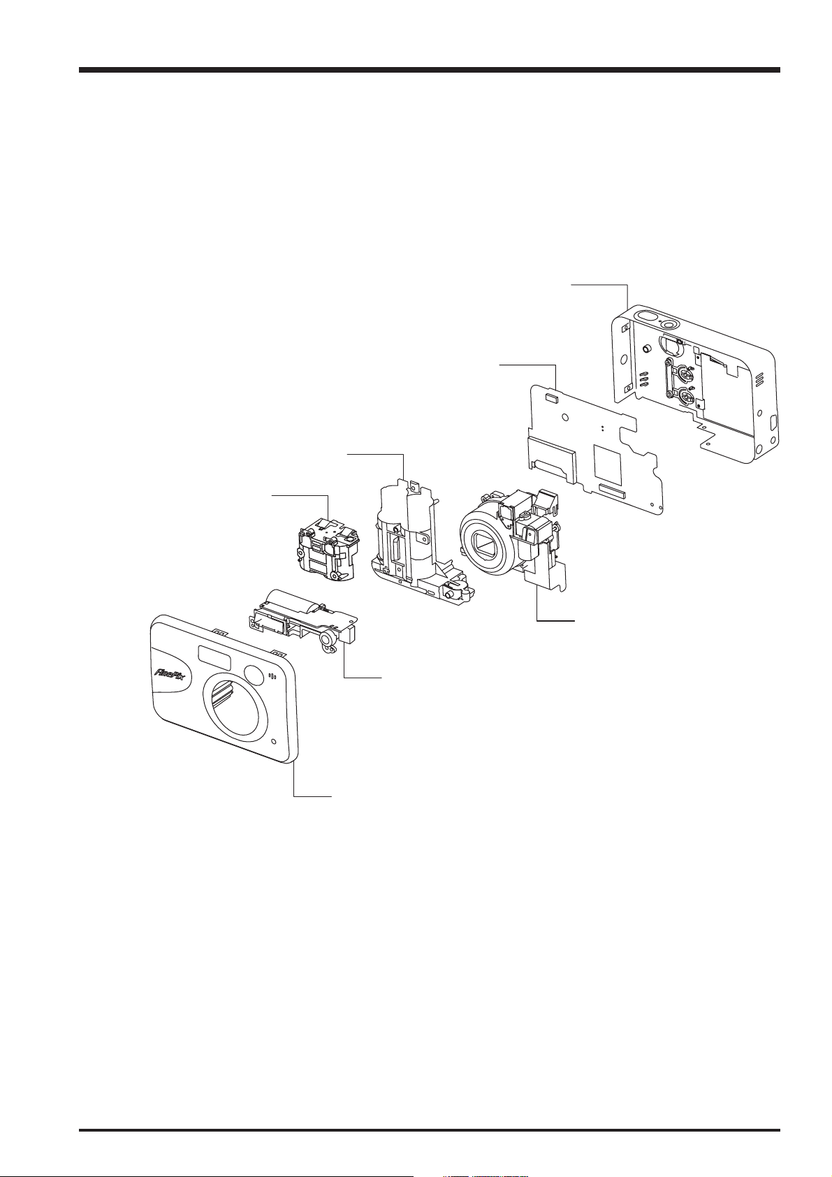
2. Disassembly
2-1. Names of internal Components
MAIN PCB UNIT
2. Disassembly
REAR COVER ASSY
FRONT BATTERY BOX ASSY
REAR BATTERY BOX ASSY
LENS UNIT
FLASH UNIT
FRONT COVER UNIT
9
2. Disassembly
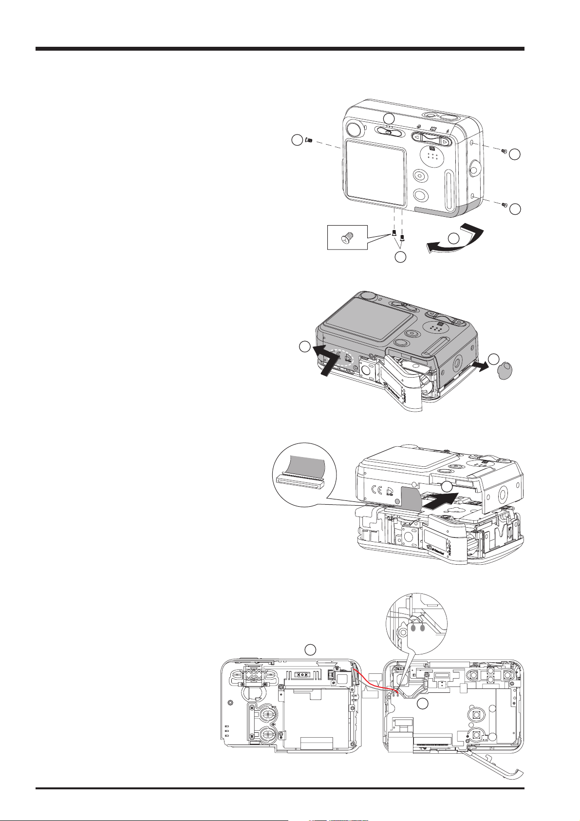
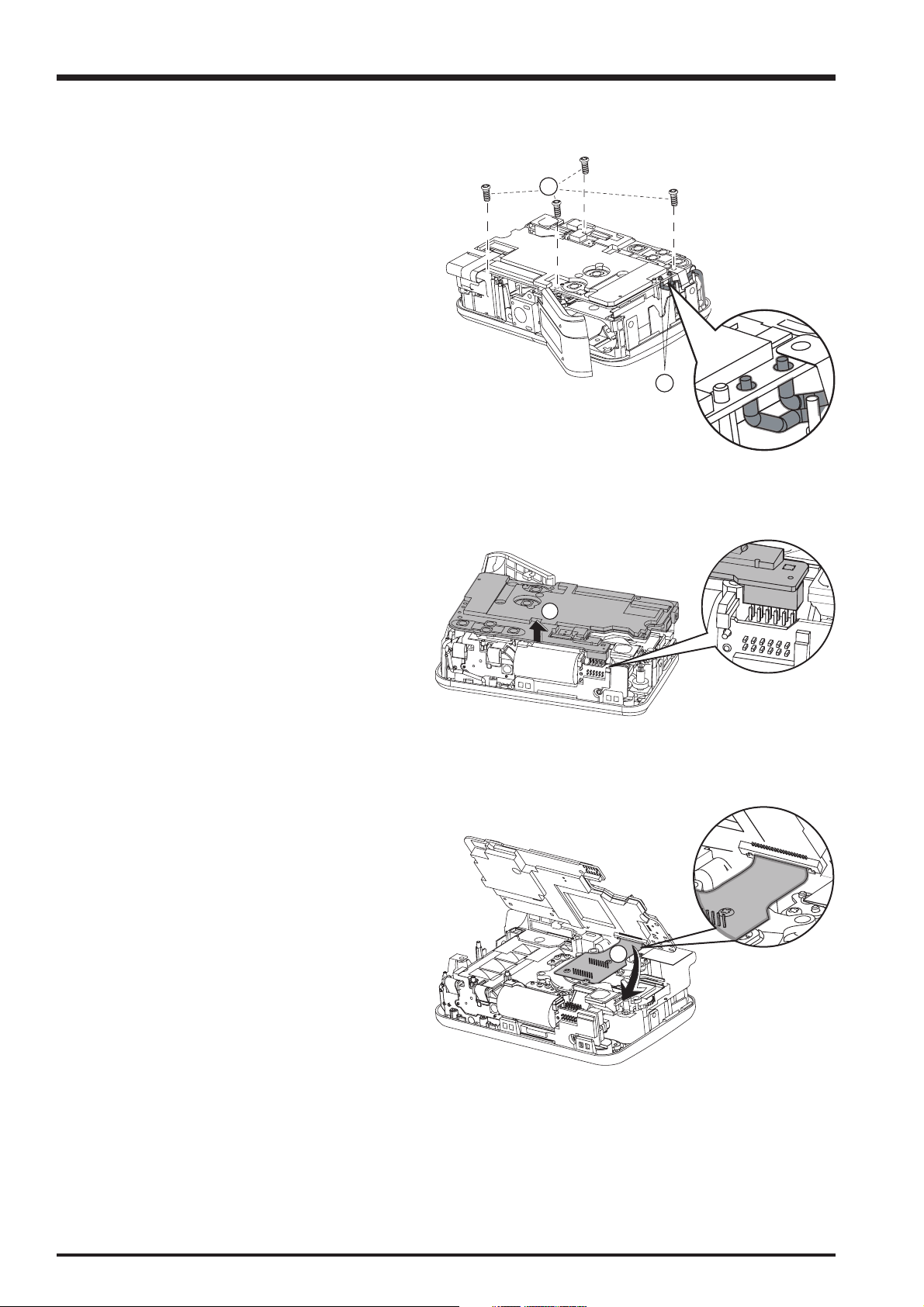
2-2. Removing the rear cover
[Disassembly]
(1) Remove two outer screws (1725 x 0.35 SILVER).
(2) Remove three outer screws (1725 x 0.50 SILVER).
Because we use special screw, the specified drive is
needed.
(3) Move the mode button to the middle (Movie mode).
(4) Open the battery cover in the direction of the arrow.
(5) Remove the rear cover in the direction of the arrow.
Remove the front cover from the rear cover a little bit.
FinePix A360 Service Manual
3
2
1
1
4
2
[Notice]
The lead line of speaker is easy to be broken.
(6) Remove the strap holder.
(7) Remove the FPC from the connecter (for LCD) in the
direction of the arrow.
The connecter is set on MB_PCB UNIT. (The right
picture is the enlarged picture of connector.)
(8) Turn the rear cover over, and remove the soldering
points of speaker lead line (The right picture is the
enlarged picture of the soldering point of speaker lead
line.)
(9) Remove the speaker.
5
6
7
- +
8
[Assembly]
To assembly, use the disassembly procedure in reverse.
10
Blach lead
line
Red lead
line
9
FinePix A360 Service Manual
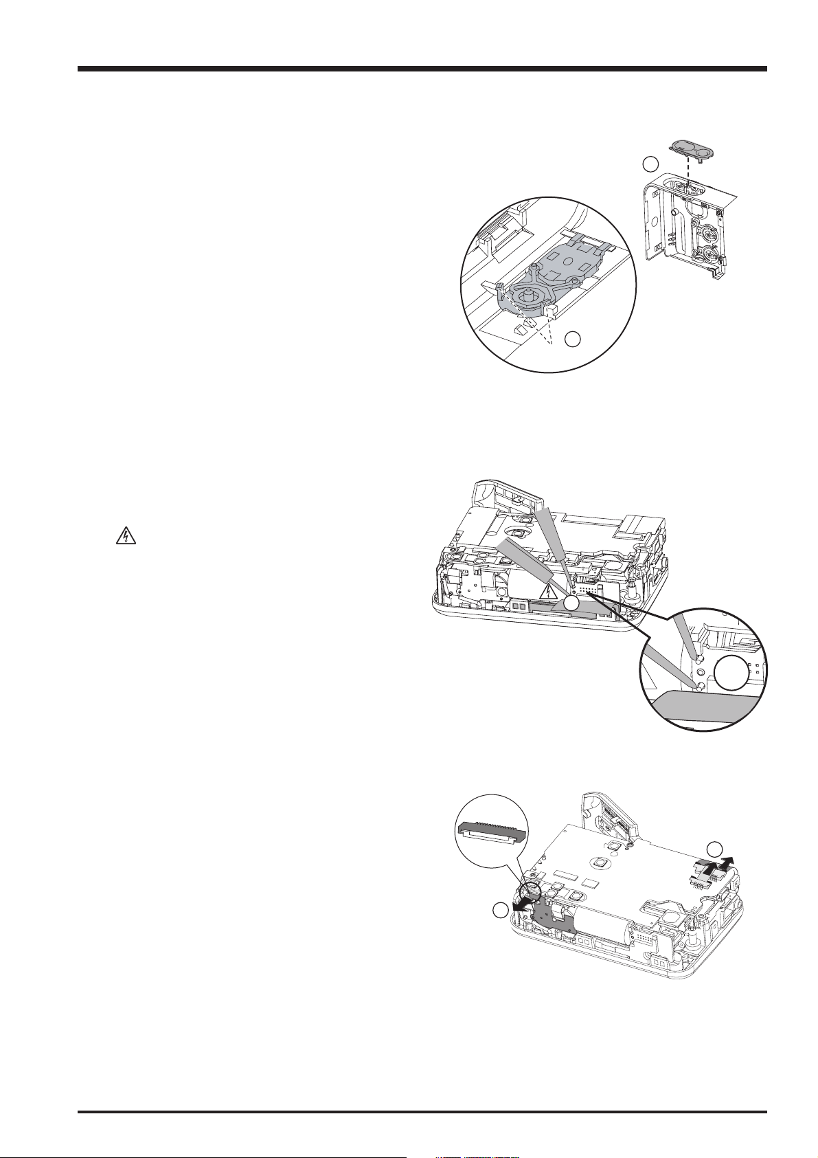
2-3. Removing the shutter button unit
[Disassembly]
(1) Press any hook slightly (Two hooks (*) are pointed out
in the right picture).
(2) Remove the shutter button unit.
2-4. Removing the MB_PCB unit
2. Disassembly
2
1
*
[Disassembly]
(1) Use tweezers to peel off the flash PCB insulating
sheet. Discharge the capacitor of STROBE_PCB unit.
[Notice]
• Make sure discharge the capacitor of STROBE_PCB unit
before remove action.
• Don’t touch STROBE_PCB unit before discharge
finishes. (The right picture show the point to discharge)
(2) Use tweezers to remove the AVFPC (A) from the
connecter (main connecter for AV) in the direction of
the arrow.
Use tweezers to remove the LENS FPC (B) from the
connecter (main connecter for lens) in the direction of
the arrow.
Use tweezers to remove the SHUTTER FPC (C) from
the connecter (main connecter for SHUTTER_FPC) in
the direction of the arrow.
1
1
2
B
A
C
2
11
2. Disassembly
(3) Remove four screws (1730 x 0.52 BLACK) of
MB_PCB unit.
(4) Remove the soldering points for power line (±) on
MB_PCB unit. (The right picture is the enlarged
picture of the soldering point.)
[Notice]
When assembly the MB_PCB unit, four screws should
follow the order of diagonal line to assembly.
FinePix A360 Service Manual
3
(5) Remove the connecter on the right bottom of
MB_PCB unit (main connecter for strobe (female)
from the connecter post (strobe connecter for main
(male)) (The right picture is the enlarged picture).
Then remove MB_PCB unit in the direction of the
arrow.
(6) Use the tweezers to remove CCD FPC from
connecter (main connecter for CCD_FPC) in the
direction of the arrow (the right picture is the enlarged
picture).
4
5
-
+
[Assembly]
To assembly, use the disassembly procedure in reverse.
12
6
FinePix A360 Service Manual
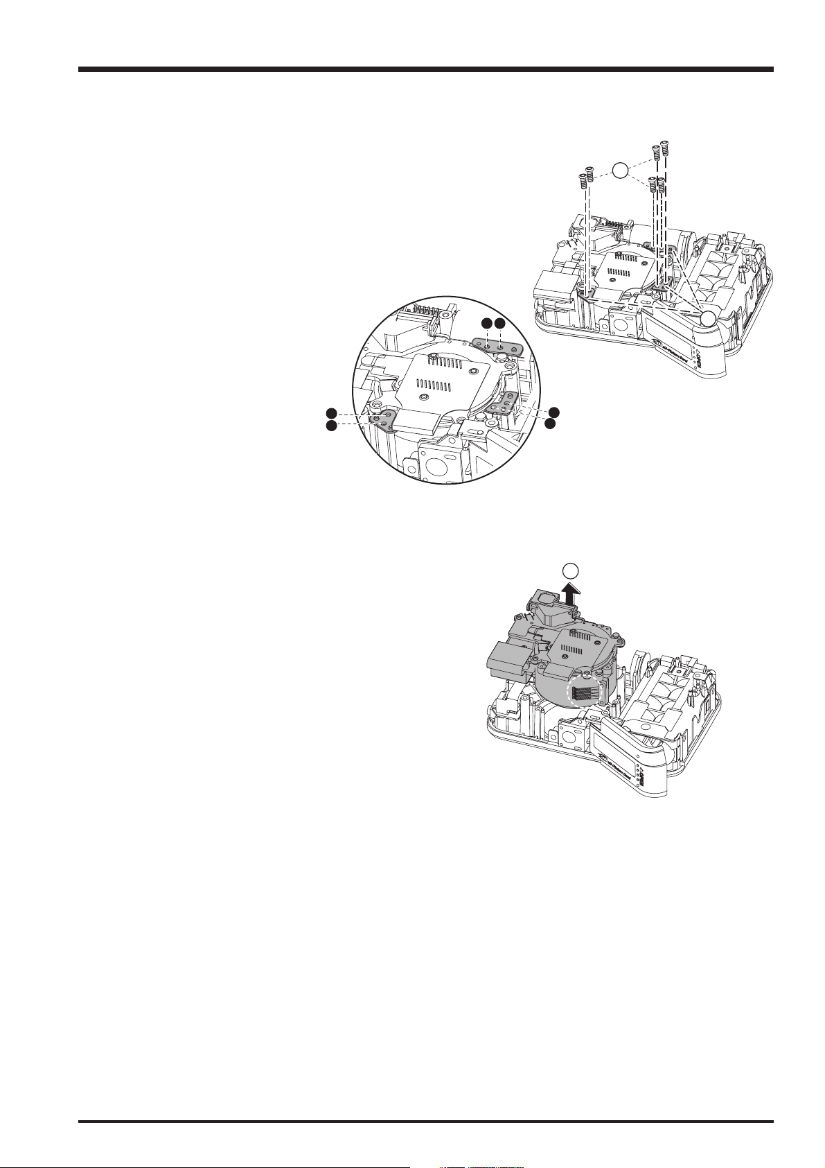
2-5. Removing the lens unit
[Disassembly]
(1) Remove six screws (1435 x 0.52 BLACK) in the top
sheet (A), middle sheet (B), bottom sheet (C) of lens.
(2) Remove the top sheet (A), middle sheet (B), bottom
sheet (C) of lens.
[Notice]
When assembly, please follow the number in the right
enlarged picture.
2. Disassembly
1
A
B
C
12
2
4
3
(3) Remove the lens unit in the direction of the arrow.
[Notice]
Please pay attention to the spring (pointed in the right
picture). The spring is easy to be out of shape.
5
6
3
13
2. Disassembly
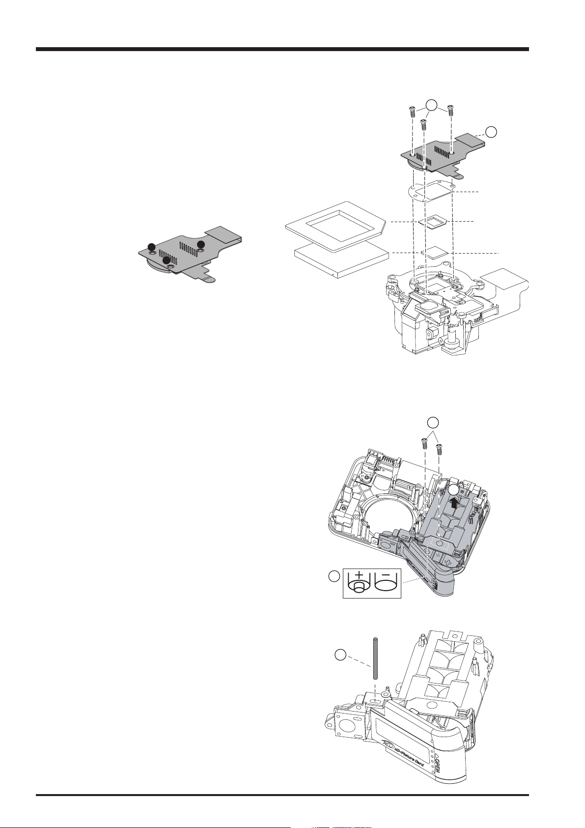
2-6. Removing the CCD
FinePix A360 Service Manual
[Disassembly]
(1) Remove three screws (1435 x 0.52 BLACK) from the
CCD metal sheet.
(2) Remove the CCD FPC unit.
[Notice]
(1) Pay attention to the cleaning of the CCD/B unit, LFP &
lens.
(2) When assembly screws, follow the number in the right
picture.
1
3
2
1
2
SHIM (0.2)
LPF RUBBER
LPF
2-7. Removing the battery box
[Disassembly]
(1) Peel off the battery box label.
(2) Remove two screws (1740 x 0.52 silver) of front
battery box.
(3) Remove the front battery & battery cover unit in the
direction of the arrow.
[Notice]
To avoid damaging the hook of front cover, please raise
from the left firstly.
(4) Open the battery cover. Remove the battery cover
axis.
2
3
1
4
Revised: 01. Jul. 2005
14
FinePix A360 Service Manual
2. Disassembly
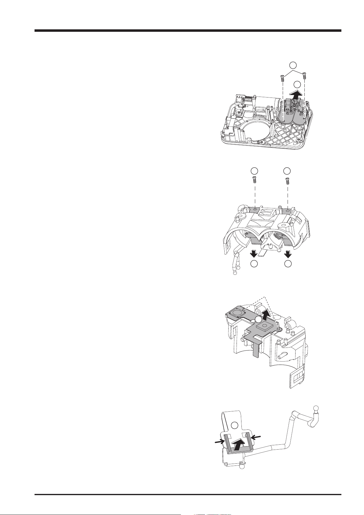
(5) Remove two screws (1740 x 0.52 silver) of the rear
battery box.
(6) Remove the rear battery box in the direction of the
arrow.
(7) Remove two screws (1435 x 0.52 black) of the battery
buffer (±).
(8) Raise the battery buffer a little, then remove the
battery buffer (±) in the direction of the arrow.
5
6
7
7
-+
(9) Peel off the shutter FPC unit in the direction of the
arrow.
[Notice]
When assembly, the two points (*) in the Shutter FPC unit
should match the two holes in the sheet.
(10) Press slightly on the two side of the battery buffer
block in the direction of the arrow, then remove it in
the direction of the bigger arrow.
8 8
*
9
10
15
2. Disassembly
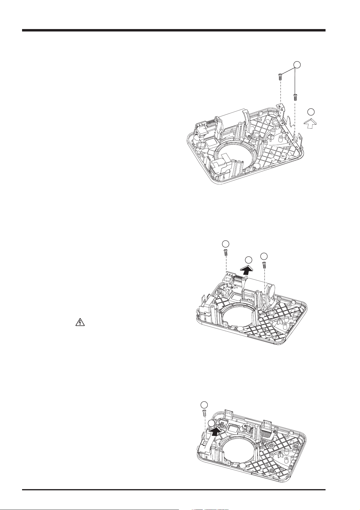
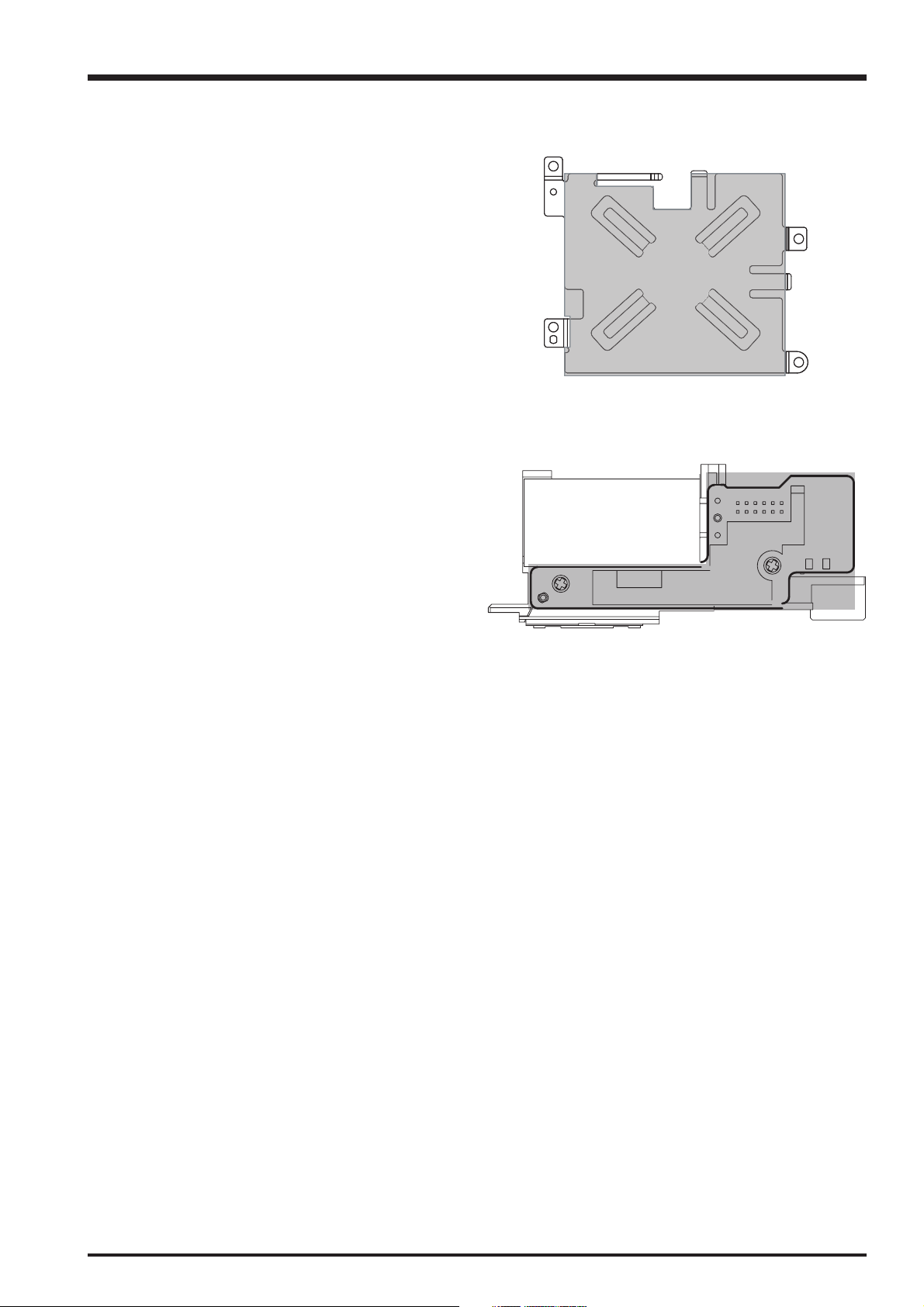
2-8. Removing the screw holder
FinePix A360 Service Manual
[Disassembly]
(1) Remove two screws (1730 x 0.52 black) of screw
holder.
(2) Remove the screw holder & copper sheet.
1
2
2-9. Removing the flash unit
[Disassembly]
(1) Remove two screws (1740 x 0.52 silver).
(2) Remove the flash PCB unit in the direction of the
arrow.
[Notice]
Make sure the capacitor of the STROBE_PCB unit
discharged already.
2-10. Removing the AV PCB
[Disassembly]
(1) Remove one screw (1730 x 0.52 black) of AV PCB.
(2) Remove the AV PCB in the direction of the arrow.
1
1
2
1
2
16
FinePix A360 Service Manual
A
2. Disassembly
2-11. Sheet component installation location specifications
1. TFT insulating sheet
(1) Attach the sheet so that it is aligned the edge
(ABCDE) of TFT holder.
(2) Make sure attach the sheet in the bottom-left corner
so that it is aligned the edge (EF) of TFT holder, and
the parts which raise high can not be covered.
2. Flash PCB insulating sheet
(1) Each ICs, screws, capacitors must be covered by the
sheet.
(2) Attach the sheet so that it is aligned the edge of Flash
FPB.
[Note]
The part surrounded by the thicker line is Flash PCB.
EE
F
F
A
A
C
C
B
E
D
D
17

3. Schematics
FinePix A360 Service Manual
3. Schematics
3-1. Cautions
<Cautions when replacing parts>
• Do not reuse removed parts. Always use new parts.
• Note that the negative side of tantalum condensers is readily damaged by heat.
• Except for chemical condensers and tantalum condensers, voltage is not displayed on condensers with a voltage
resistance of 50V or less.
• Resistors not marked are 1/16W chip resistors.
•KΩ = 1000Ω, MΩ = 1000KΩ
3-2. Basic Block Names and Functions
Part name Block name Function
CCD CCD BLOCK CCD Output (U400)
MAIN PWB CAM BLOCK CCD output A/D conversion (U901), CCD drive (U901)
PROCESS BLOCK Image signal processing (U100), SDRAM (U102)
RTC BLOCK Clock generator (U901)
MOTOR BLOCK Shutter/Iris/AF/Zoom drive (U200)
DCDC BLOCK Power supply generation (U300)
NOR FLASH BLOCK Program strobe (U101)
AUDIO BLOCK MIC/SPEAKER (U500)
KEY BLOCK Switch
STROBE STROBE BLOCK Flash
LCD UNIT LCD display
18

FinePix A360 Service Manual
3. Schematics
3-3. Description of Main Block Functions
3-3-1. Technical Overview
Equipped with a 1/2.5-inch square-pixel interline CCD (total pixels 4.23 million pixels). Use memory card [XD-picture card].
Feature the new lens system with 3x optical zoom.
Features a new IC, which can do CCD processing (TG, V/D, A/D 3-int-1) AD9905, OS processing, Functions control FUJITSU
M-2a/Spec 1.2E, Power control function (RT9903PQV&RT9201QPV), TV enlarged output function (AN12909).
Flash block module.
Camera equipped with an internal speaker, and real sound record when movie plays.
3-3-2. MAIN Board Block Functions
Explanation of each block
CCD block / CAM block
Analog video signals output from the CCD Equipped with a 1/2.5-inch square-pixel interline CCD (total pixels 4.23 million
pixels) (U400)) undergo pseudo-color correction processing, adaptive interpolation processing, amplification (AGC) and
signal mixing. Then the analog video signal is converted to 12bit digital signal, and sent to the DSP system.
Motor block
The DSP (M-2a/Spec 1.2E), which receives the command do signal from each operation system, control the motor drive
IC (TB6557FLG U200), and control the motor of AF/Shutter/Zoom/Iris.
Signal Process block
Input data from CCD
The 12bit digital image data sent from the CCD/CAM block is sent to DSP of camera (inside the DRAM (16 M byte)),
which equals to 1 frame (2304 pix x 1728pix) is temporarily stored. At the same time, the image data sent to DSP is
calculated in [Auto calculation block], to obtain the correct AE/AWB/AF. The data is sent to and temporarily stored in
SDRAM.
Recording onto an XD-Picture card
The data temporarily stored in the SDRAM U102 (K4S281633F-BN75T00 is sent to the internal [Signal process block] in
each line of DSP to undergo unpack process “32bit -> 10bit conversion”, “Digital clamp, γ correction, R/G/B each 10bit
->R/G/B each 8bit conversion pre-processing” -> “each 8bit digital R/G/B signal -> Y: Cb: Cr=4: 2: 2 YC processing”.
The image data of Y/Cb/Cr each 8bit is sent to the inside buffer — SDRAM. [Inside buffer—SDRAM] change “each Y/Cb/
Cr signal of 8bit into the easily changed DCT pattern”. By the DSP [JPEG calculation compression] -> [Media controller] >SDRAM, and last stored in the XD-Picture card.
Playing back image data from an XD-Picture card
The compressed 8bit image data from the XD-Picture card is sent to it “SDRAM” -> DSP “MEDIA control section” ->
[DMAUNIT] -> [Inside DRAM (16Mbyte)] -> [Media controller] -> [JPEG calculation block] -> [Signal process block].
The imaging system adjustment data is stored by Flash ROM.
LCD unit
The digital signal from DSP system is sent to the drive IC of LCD unit, through the process block of LCD FPC to undergo
LCD drive and LCD panel adjustment control.
DCDC BLOCK
The power supply circuits on the DCIC (U300), IC (U302), and IC (RT9178 U902) generate power supplies to following
blocks.
3V3M [DSP (U100), AD9925 (U901), FLASH ROM (U101), SDRAM (102)], STROBE IC (U801), MOTOR Drv.
(U200), XD-Picture Card, TFT, Audio process IC (U500), Video process IC (U11), CCD IC (U400), STROBO
IC (U801)
1V8M DSP (U100)
LEDA color TFT
LEN_3V3 LENS DRIVER IC (U200)
CCD12V [CCD (U400), AD9925 (U901)]
CCD6VN [CCD (U400), AD9925 (U901)]
CCDA3 AD9255 (U901)
19

Imag e Proce ss
Un it
1
6
CA
RD
M
AI N PWB
DCD C BL OCK
AUD IO
B
L
OCK
Pic t
u
re
KEY
BL
OC
K
F
R71
E
32
-
bit
RIS C
co
r
e
LEN S
B
LOCK
V
IDE O
OUT
LCD
LENS
USB
xD
P
ROC
ES
S
PW
B
CCD
FPC
J
A
C
K&S
W
PW
B
S
TR
OBE
P
WB
D
SP
3. Schematics
3-4. Block Diagram
FPC
CCD
LENS
3xZOOM
O
L
P
F
IC400
MN39482
12V/-8V
CCD
CCDOUT
H1&H2
V [6:1]
HL
SUBSW
RG
SVO_1
SVO_2
SVO_3
SVO_4
A-
A+
B-
B+
DM+
DM-
IC200
TB6557FLG
3.3V
MOT
Drv.
CCD
DRIVER
AFE&TG
IC901
AD9925
12V/-8V
LENS
CCDCLK:27M
SCLK
SDATA
CS_LEN
LEN_C
LEN_SW[1:3]
FOCUS_PI
Z_PI
LEN_SW[1:3]
BLOCK
CCDATA [10:0]
HAYNC
VSYNC
MCLK
RESET
CS-CCD
SDATA
SCLK
27MHZ
48MHZ
Image Process
AE/AF/AWB
Resolution
Conv.
S
I
O
I/O I/F
U
S
B
FR71E
32-bit
RISC
core
FinePix A360 Service Manual
Unit
YCPRO
JPEG
IC100
Fujitsu M-2A/spec 1.4E
3.3V/1.8V
VIDEO
Encoder
C-DAC
DRAM&FLASH I/F
Media I/F
DSP
LCDDATA[7:0]
LCDVD
LCDHD
BL_ON
LCD_ON
LCD_CLK
LCD
AU 1.7"
USB
VIDEO
Drv.
IC11
TK15465S-G
3.3V
16
IC101
MAX29LV160
3.3V
FLASH
16MBit
SDRAM
256MBit
IC102
K4S561633F
3.3V
XD CARD
SOCKET
PROCESS PWB
A017CN01
3.3V
FROM
KEY
LCD
USB
VIDEO
OUT
xD
Picture
CARD
16M
32M
64M
128M
265M
512M
4
GE
R
HA
F_C
F_STROBE
IN
CV
D
STROBE PWB
STROBE
IC801
RT9590
3.3V
3
PWR_ON
PWR_OFF
MOTOR ON
CCD_ON
LCD_ON
SPEAKER
MIC
ON
POWER
SHUTTER
FOCUS
JACK&SW PWB
TO
TV
Drv.
DCDC B
DC IC
IC300
RT9903PQV
LOCK
MAIN PWB
+3.3V
+1.8V
+12V
-8V&-6V
BAT
DC in
SDATA
SCLK
CS_AUDIO
AUDIO
DACOUT
ACOUT
AUDIO BLOCK
STROB LED
FOCUSLED
SELF_LED
CHERGE_ON
F_READY
O
KEY BLOCK
Drv.
IC500
AN12909
3.3V
KEY
Process
NT/PAL
POWER ON
SHUTTER
FOCUS
KEYIN0
KEYIN1
20
 Loading...