

FUJIFILM FinePix A330 SERVICE MANUAL
DIGITAL CAMERA
A330
SERVICE MANUAL
JP/US/EU/EG/GE/CA/AS/CH-Model
WARNING
THE COMPORNENTS IDENTIFIED BY THE MARK “ ” ON THE SCHEMATHIC
DIAGRAM AND IN THE PARTS LIST ARE CRITICAL FOR SAFETY.
PLEASE REPLACE ONLY BY THE COMPONENTS SPECIFIED ON THE SCHEMATHIC
DIAGRAM AND IN THE PARTS LIST.
IF YOU USE WITH PART NUMBER UN-SPECIFIED, IT MAY RESULT IN A FIRE AND AN
ELECTORICAL SHOCK.
Ref.No.:ZM00540-102
FUJI PHOTO FILM CO.,LTD.
Printed in Japan 2004.04(T.S.)
FinePix A330 SERVICE MANUAL
SAFETY CHECK-OUT
After correcting the original problem, perform the following
safety check before return the product to the customer.
1. Check the area of your repair for unsoldered or poorly
soldered connections. Check the entire board surface
for solder splasher and bridges.
2. Check the interboard wiring to ensure that no wires are
“pinched” or contact high-wattage resistors.
3. Look for unauthorized replacement parts,
particularly transistors, that were installed during a
previous repair. Point them out to the customer and
recommend their replacement.
4. Look for parts which, though functioning, show obvious
signs of deterioration. Point them out to the customer and
recommend their replacement.
5. Check the B + voltage to see it is at the values specified.
6. Make leakage - current measurements to determine
that exposed parts are acceptably insulated from the
supply circuit before returning the product to the customer.
7. CAUTION: FOR CONTINUED
PROTECTION AGAINST FIRE
HAZARD, REPLACE ONLY WITH
SAME TYPE 2.5 AMPERES 125V
FUSE.
RISK OF FIRE-
2.5A125V
2.5A125V
8.
WARNING!
HIGH VOLTAGE
REPLACE FUSE
AS MARKED
ATTENTION: AFIN D'ASSURER
UNE PROTECTION
PERMANENTE CONTRE LES
RISQUES D'INCENDIE,
REMPLACER UNIQUEMENT
PAR UN FUSIBLE DE MEME,
TYPE 2.5 AMPERES, 125 VOLTS.
WARNING:
TO REDUCE THE ELECTRIC
SHOCK, BE CAREFUL TO
TOUCH THE PARTS.
2

FinePix A330 SERVICE MANUAL
CONTENTS
1.General
1-1. Product specification.......................................................... 4
1-2. Explanation of Terms ......................................................... 6
1-3. Names of External Components....................................... 7
2. Disassembly
2-1. Names of internal Components ........................................ 8
2-2. Removing CABI R ASSY ................................................... 9
2-3. Removing LCD CONST ..................................................... 9
2-5. Removing ST BLOCK ......................................................10
2-4. Removing DSC BLOCK ................................................... 10
2-6. Method of disassembling ST BLOCK ............................. 11
2-7. Removing LENS BLOCK ................................................. 11
2-8. Method of disassembling LENS BLOCK .......................12
2-9. Removing ENGINE PWB ASSY ...................................... 12
2-10. Removing BATTERY HOLDER ASSY ......................... 13
2-11. Removing LENS BARRIER ...........................................13
Table of Contents
Page Page
4-8. Starting the Adjustment Software................................... 32
4-9. [R] : Flash Memory Reset................................................ 35
4-10. [F4] : CCD Defect Data Input........................................ 37
4-11. [F5] : CAM Adjustment ................................................... 39
4-12. [F6] : AF Adjustment ......................................................42
4-13. [F7] : Flash Adjustment .................................................44
4-14. [F1] : Battery Voltage Adjustment ................................ 46
4-15. [F3] : LCD Adjustment ...................................................50
4-16.[F11] : Video Adjustment ................................................52
4-17. [F12] : End Setting ......................................................... 54
4-1 9 . [ F8 ] : Fi r m w ar e D o wn l o a d .............................................. 58
5. Inspection
5-1. Required Measuring Equipment .....................................60
5-2. Connection of Measuring Equipment............................. 60
5-3. Inspection and Factory Settings .....................................60
6. Parts List
3. Schematic
3-1. Cautions ............................................................................. 15
3-2. Basic block name and function explanation .................. 15
3-3.Functions of Primary Blocks ............................................. 16
3-3-1.Technical Outline .................................................... 16
3-3-2.MAIN Board Block Functions ................................16
3-3-3.ENGINE Board Block Functions...........................16
3-4. Block Diagram...................................................................17
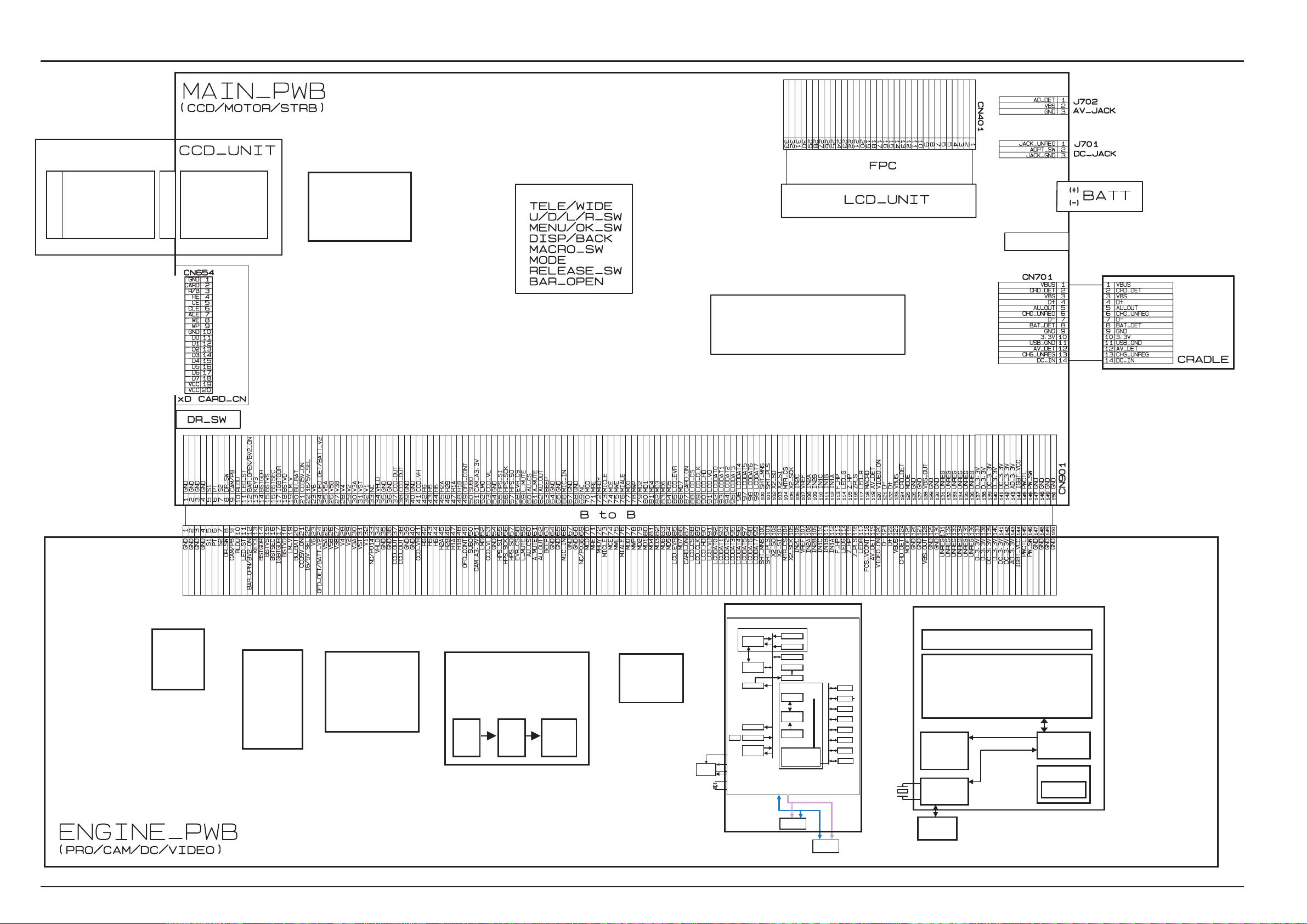
3-5. Overall Connections......................................................... 18
3-6. Board mounting diagram ................................................. 19
3-6-1. Printed wiring board of MAIN PWB ASSY .........19
3-6-2. Printed wiring board of ENGINE PWB ASSY ....20
3-6-3. Printed wiring board of RSW PWB ASSY .......... 21
3-7.Circuit diagram .................................................................. 22
3-7-1. RSW BLOCK Circuit .............................................22
3-7-2. ENGINE BLOCK Circuit ........................................ 23
3-7-3. MAIN BLOCK Circuit............................................. 24
4. Adjustment
4-1. Important point Adjustment when Replacing Major Parts.... 25
4-2. Measuring Instruments Used ..........................................25
4-3. Use Jig list.........................................................................25
4-4. Method of remodeling Fx-A310Batt. jig .........................26
4-5.Calibration method of pattern box ...................................27
4-6. Adjusting soft installation ................................................27
4-6-1. Various downloading software decompressions,
preservation methods, and notes ................................... 27
4-6-2. Installation of DSC jig driver ................................28
4-6-3. Adjusting soft initiation method ........................... 28
4-7. Initial Settings of the Adjustment Software ...................29
6-1. Packing and Accessories ................................................ 62
6-1-1. US-MODEL ............................................................. 62
6-1-2. EU-MODEL ............................................................. 63
6-1 - 3 . EG - M O DE L ............................................................6 4
6-1-4. CA-MODEL ............................................................. 65
6-1 - 5 . GE - M O DE L ............................................................6 6
6-1-6. AS-MODEL............................................................. 67
6-1-7. CH-MODEL ............................................................68
6-1-8. JP-MODEL .............................................................69
6-2. Mechanical parts(ALL-MODEL)...................................... 70
6-3 . E l ec t r o ni c p a rt s ................................................................. 71
7.Appendix
7-1.Function of display for Firmware Version...................... 72
7-2.List of Related Technical Updates Issued...................... 73
3
1.General
FinePix A330 SERVICE MANUAL
1.General
1-1. Product specification
System
Model Digital camera FinePix A330
Number of effective pixels
CCD sensor 1/2.7 inch square pixel CCD Number of total pixels 3.34 million pixels
Number of recorded pixels
Storage media xD-Picture Card (16/32/64/128/256/512 MB)
File format Still image: JPEG (Exif ver. 2.2)
Lens Fujinon 3× optical zoom lens, F2.8-F4.8
Aperture F2.8 to F4.8/F5.6 to F9.5 (automatically selected)
Focal length f=5.7 mm to 17.1 mm (Equivalent to 38 mm to 114 mm on a 35 mm camera)
Focal range Normal: Approx. 0.6 m (2.0 ft.) to infinity
Shutter speed 2 sec. to 1/2000 sec. (combined with mechanical shutter)
Focus TTL contrast-type, Auto focus
Sensitivity Equivalent to ISO100 (at flash off)
Photometry TTL 64-zones metering
Exposure control Program AE
Exposure compensation
White balance Auto
Viewfinder Real image optical Approx. 80% coverage
LCD monitor 1.5-inches, 60,000-pixel Amorphous silicon TFT, Approx. 90% coverage
Flash Auto flash using flash control sensor
Self-Timer 10 sec.
Video output NTSC/PAL selectable
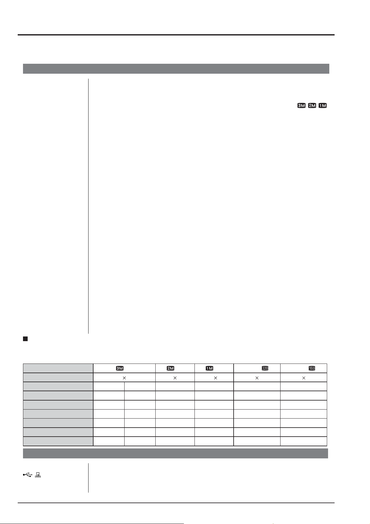
Standard number of available frames/recording time per xD-Picture Card
The number of available
that the divergence between standard number of available
xD-Picture Cards with higher capacities.
Quality Setting
Number of recorded pixels
Image Data Size
DPC-16 (16 MB)
DPC-32 (32 MB)
DPC-64 (64 MB)
DPC-128 (128 MB)
DPC-256 (256 MB)
DPC-512 (512 MB)
3.2 million pixels
Still image: 2016 × 1512 pixels/1600 × 1200 pixels/1280 × 960 pixels (/ / )
Movie: 320 × 240 pixels (10 frames per second without sound)
160 × 120 pixels (10 frames per second without sound)
* Design rule for Camera File System compliant DPOF compatible
Movie: AVI format, Motion JPEG
Macro: Approx. 0.1 m (3.9 in.) to 0.8 m (2.6 ft.)
-2.1 EV to +1.5 EV in 0.3-step increments (in Manual mode)
Manual modes, 7 positions can be selected
Effective range: Wide-angle: Approx. 0.6 m to 3.5 m (2.0 ft. to 11.5 ft.)
(Approx. 0.3 m to 0.8 m (1.0 ft. to 2.6 ft.): Macro)
Telephoto: Approx. 0.6 m to 3.0 m (2.0 ft. to 9.8 ft.)
Flash modes: Auto, Red-Eye Reduction, Forced Flash, Suppressed Flash, Slow
Synchro*, Red-Eye Reduction + Slow Synchro* * In Manual mode
, recording time or file size varies slightly depending on the subjects photographed. Note also
frames
2016 1512
FINE 1.5 MB
10
20
42
84
169
339
frames
3M
1600 1200
NORMAL 760 KB
20
41
82
166
332
665 818 1101
620 KB
and the actual number of available
2M
25
50
101
204
409
1M
1280 960
460 KB
33
68
137
275
550
Movie
320 240
–
Approx. 98 sec.
Approx. 199 sec.
Approx. 6.6 min.
Approx. 13.3 min.
Approx. 26.7 min.
Approx. 53.5 min.
is greater for
frames
Movie
160 120
–
Approx. 5.6 min.
Approx. 11.3 min.
Approx. 22.7 min.
Approx. 45.5 min.
Approx. 91.2 min.
Approx. 182.5 min.
Input/Output Terminals
Video output socket 2.5 mm dia. jack
(USB) socket For file transfer to a computer and connection to the optional cradle
DC Input Socket for specified AC power adapter AC-3V (sold separately)
Connection for the AC Power Adapter AC-3VW bundled with the cradle (sold separately)
4

FinePix A330 SERVICE MANUAL
1.General
Power Supply and Others
Power supply Use one of the following:
• 2×AA-size alkaline batteries
• Rechargeable Battery NH-10 (sold separately)
• 2×AA-size Ni-MH (Nickel-Metal Hydride) batteries (sold separately)
• AC-3VW (PictureCradle CP-FXA10, sold separately)
• AC Power Adapter AC-3V (sold separately)
Guide to the number
of available frames
for battery operation
The number of available frames for battery operation given here is a guide to the
number of consecutive shots that can be taken under FUJIFILM test conditions.
• Batteries used: alkaline batteries bundled with the camera fully charged Ni-MH
• Shooting conditions: Measured at normal temperature with 50% flash use
• Note: Because the number of available frames that can be taken varies depending
Conditions for use Temperature: 0oC to +40oC (+32oF to +104oF); 80% humidity or less (no condensation)
Camera dimensions 104.1 mm × 61.5 mm × 31.3 mm/4.1 in. × 2.4 in. × 1.2 in.
(W/H/D) (not including accessories and attachments)
Camera mass (weight)
Weight for photography
Accessories 16 MB, xD-Picture Card (1) Included with: Anti-static case (1)
Approx. 145 g/5.1 oz. (not including accessories, batteries and xD-Picture Card)
Approx. 193 g/6.8 oz. (including batteries and xD-Picture Card)
Battery Type With LCD monitor ON With LCD monitor OFF
Alkaline batteries Approx. 160 frames Approx. 250 frames
Rechargeable Battery
NH-10
Ni-MH batteries 2300 mAh Approx. 250 frames Approx. 350 frames
batteries or the NH-10 Rechargeable Battery
on the capacities of alkaline batteries and the amount of charge in Ni-MH batteries or NH-10 Rechargeable Battery, the figures given here for the number of
frames that can be taken using batteries are not guaranteed. At low temperatures, fewer pictures can be taken when the camera is running on batteries.
Approx. 200 frames Approx. 280 frames
LR6 AA-size alkaline Batteries (2) Strap (1)
Video cable (1) 2.5 mm dia. plug-to-pin plug Approx. 1.5 m (4.9 ft.)
USB cable with Noise Suppression core (1)
Cradle adapter for FinePix A330 (1)
CD-ROM: Software for FinePix AX (1) Owner’s Manual (1)
Optional Accessories xD-Picture Card
DPC-16 (16 MB)/DPC-32 (32 MB)/DPC-64 (64 MB)/DPC-128 (128 MB)/
DPC-256 (256 MB)/DPC-512 (512 MB)
AC Power Adapter AC-3V Fujifilm Rechargeable Battery 2HR-3UF
Fujifilm Battery Charger with Battery BK-NH/BK-NH2 (With Euro type or UK type plug)
PictureCradle CP-FXA10 Rechargeable Battery NH-10
Carrying Case SC-FXA02
Image Memory Card Reader DPC-R1
• Compatible with Windows 98/98 SE, Windows Me, Windows 2000 Pro-
fessional, Windows XP or iMac, Mac OS 8.6 to 9.2.2, Mac OS X
(10.1.2 to 10.2.2) and models that support USB as standard.
• Compatible with xD-Picture Card of 16 MB to 512 MB, and SmartMedia
of 3.3V, 4 MB to 128 MB.
PC Card Adapter DPC-AD
• Compatible with xD-Picture Card of 16 MB to 512 MB, and SmartMedia
of 3.3V, 2 MB to 128 MB.
CompactFlash Card Adapter DPC-CF
• Windows 95/98/98 SE/Me/2000 Professional/XP
• Mac OS 8.6 to 9.2/X (10.1.2 to 10.1.5)
xD-Picture Card USB Drive DPC-UD1
• Compatible with xD-Picture Card of 16 MB to 512 MB
• Windows 98/98 SE/Me/2000 Professional/XP
• Mac OS 9.0 to 9.2/X (10.0.4 to 10.2.6)
5

1.General
1-2. Explanation of Terms Deactivated batteries: Leaving an Ni-MH battery unused in storage for a long period may cause a rise in
the level of substances that inhibit current flow inside the battery and result in a
dormant battery. A battery in this state is referred to as deactivated.
Because current flow is inhibited in a deactivated Ni-MH battery, the battery’s
original level of performance cannot be achieved.
DPOF: Digital Print Order Format
DPOF is a format used for recording information on a storage media (image
memory card, etc.) that allows you to specify which of the frames shot using a
digital camera are to be printed and how many prints are made of each image.
EV: A number that denotes Exposure Value. The EV is determined by the brightness
of the subject and sensitivity (speed) of the film or CCD. The number is larger for
bright subjects and smaller for dark subjects. As the brightness of the subject
changes, a digital camera maintains the amount of light hitting the CCD at a constant level by adjusting the aperture and shutter speed.
When the amount of light striking the CCD doubles, the EV increases by 1. Likewise, when the light is halved, the EV decreases by 1.
FinePix A330 SERVICE MANUAL
Frame rate (fps): The frame rate refers to the number of images (frames) that are photographed or
played back per second. For example, when 10 frames are continuously photographed in a 1-second interval, the frame rate is expressed as 10 fps.
For reference, TV images are displayed at 30 fps.
JPEG : Joint Photographics Experts Group
A file format used for compressing and saving color images. The higher the
compression rate, the greater the loss of quality in the decompressed (restored) image.
Memory effect: If an Ni-MH battery is repeatedly charged without first being fully discharged, its
performance may drop below its original level. This is referred to as the “memory
effect”.
Motion JPEG: A type of AVI (Audio Video Interleave) file format that handles images and sound
as a single file. Images in the file are recorded in JPEG format. Motion JPEG can
be played back by QuickTime 3.0 or later.
PC Card: A generic term for cards that meet the PC Card Standard.
PC Card Standard: A standard for PC cards determined by the PCMCIA.
PCMCIA: Personal Computer Memory Card International Association (US).
White Balance: Whatever the kind of the light, the human eye adapts to it so that a white object
still looks white. On the other hand, devices such as digital cameras see a white
subject as white by first adjusting the color balance to suit the color of the ambient light around the subject. This adjustment is called matching the white balance.
Exif Print: Exif Print Format is a newly revised digital camera file format that contains a vari-
ety of shooting information for optimal printing.
6
FinePix A330 SERVICE MANUAL
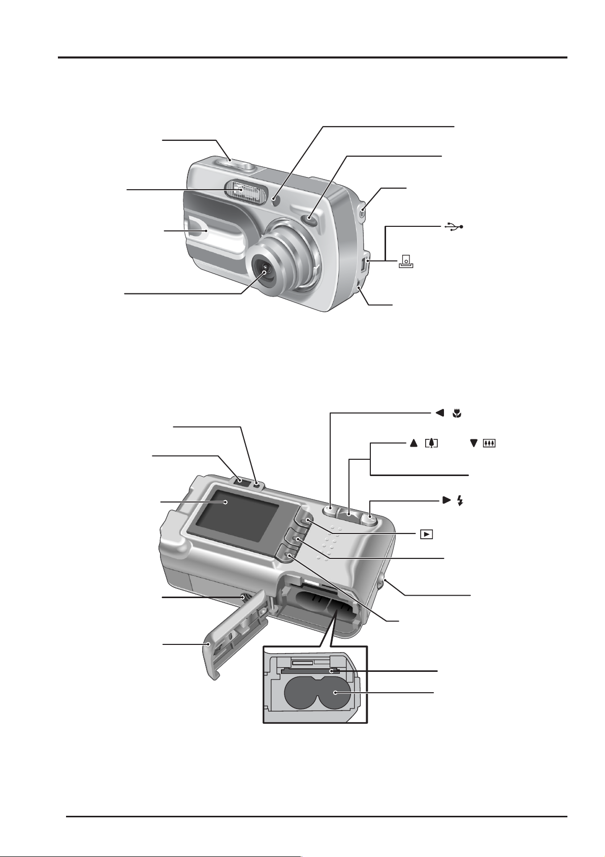
1-3. Names of External Components
Shutter button
1.General
Self-timer lamp
Viewfinder window
Flash
Power switch /
lens cover
Lens
Viewfinder lamp
Viewfinder
VIDEO OUT (Video output)
socket
(USB)socket
Cradle connection socket
DC IN 3V (Power input) socket
/ (Macro) button
/ (Tele), / (Wide)
Zoom switch
LCD monitor
Tripod mount
Battery cover
/ (Flash) button
ON (Playback) button
MENU / OK button
Strap mount
DISP (Display) / BACK button
xD-Picture Card slot
Battery compartment
7
2. Disassembly
2.Disassembly
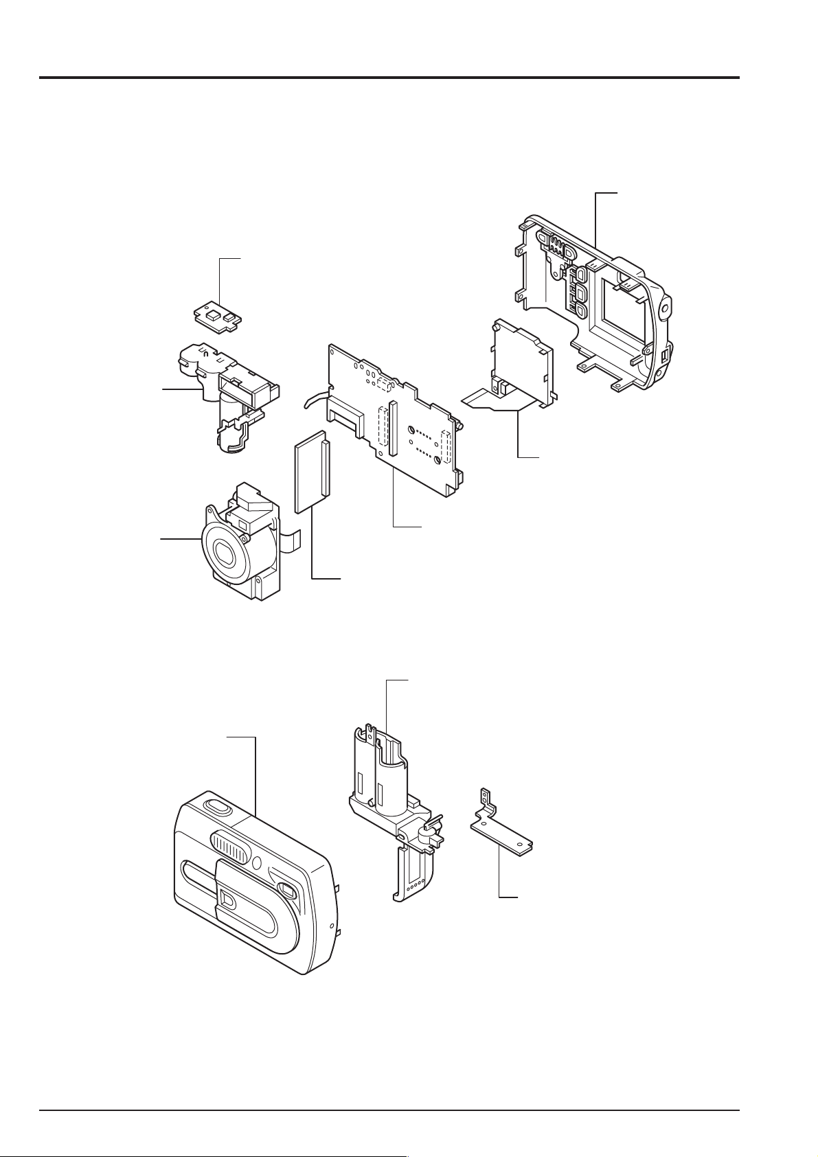
2-1. Names of internal Components
RSW PWB ASSY
ST BLOCK
FinePix A330 SERVICE MANUAL
CABI R ASSY
LCD CONST
LENS BLOCK
CABI F ASSY
MAIN PWB ASSY
ENGINE PWB ASSY
BATT ASSY
BOTTOM PLATE
8
FinePix A330 SERVICE MANUAL
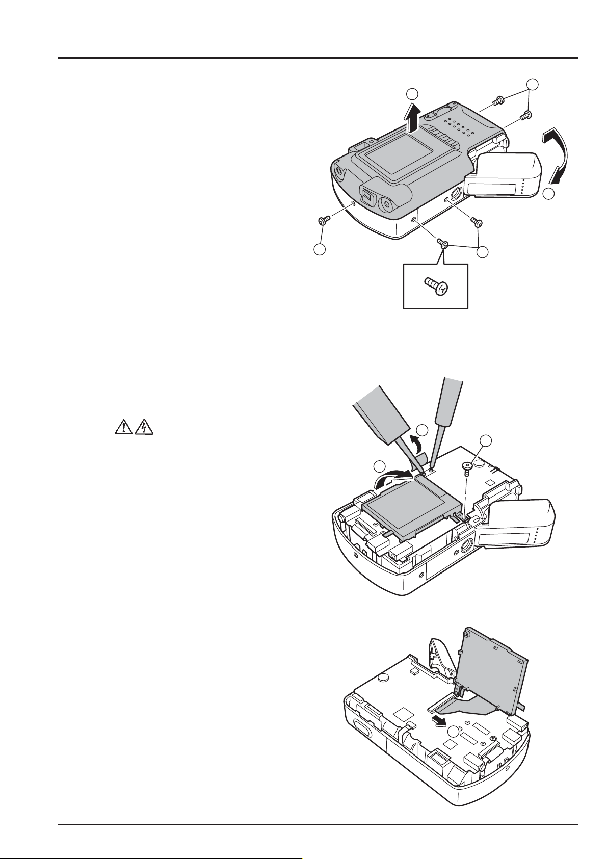
2-2. Removing CABI R ASSY
* Remove in the order indicated by circled numbers.
< Step 1 >
(1) Remove five screws.
(** Remove it when there is a battery.)
(2) Remove the battery cover.
(3) Remove CABI R ASSY in the direction of the arrow.
[ Assembly ]
(1) Assemble it in the reverse order of disassembling.
(2) Tighten the screw so as not to make the space in
"CABI R ASSY" and "CABI F ASSY".
2. Disassembly
3
1
Screw of special shape.
Use the driver of Jig number (ZJ00583-100).
1
1
2
2-3. Removing LCD CONST
* Remove in the order indicated by circled numbers.
< Step 1 >
(1) Peel off the UL tape, and discharge the flash.
(2) Remove one screws.
(3) Raise LCD CONST.
< Step 2 >
(4) Remove the lock of the connector,
and remove LCD CONST.
1
2
3
4
9
2. Disassembly
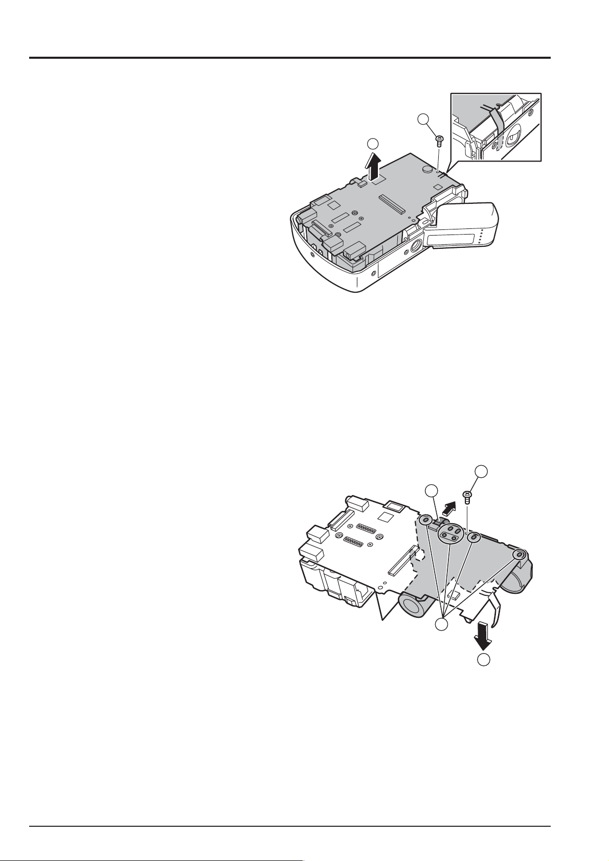
2-4. Removing DSC BLOCK
* Remove in the order indicated by circled numbers.
< Step 1 >
(1) Remove one screws.
(2) Remove DSC BLOCK in the direction of the arrow.
[ Assembly ]
(1) Assemble it in the reverse order of disassembling.
FinePix A330 SERVICE MANUAL
1
2
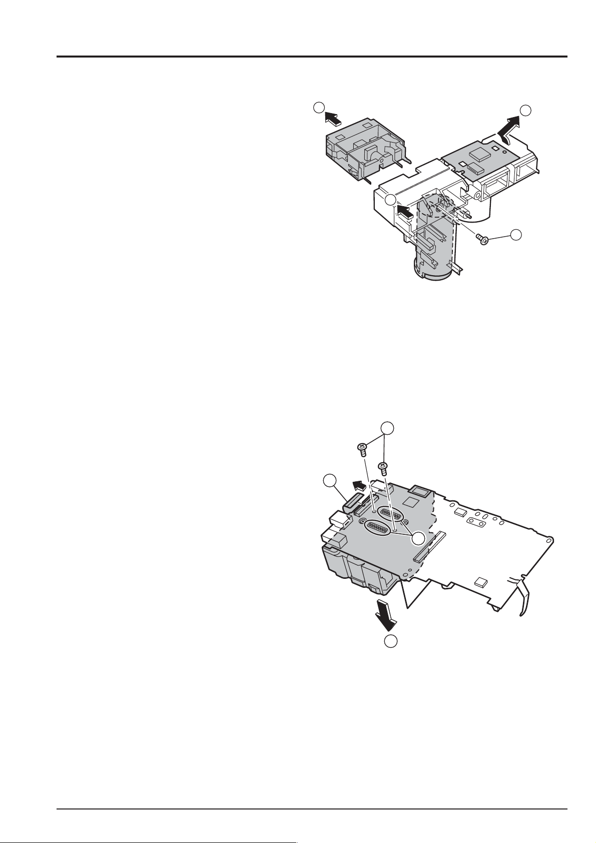
2-5. Removing ST BLOCK
* Remove in the order indicated by circled numbers.
< Step 1 >
(1) Pull out FFC from the connector.
(2) Remove solder in seven places.
(3) Remove one screws.
(4) Remove ST BLOCK in the direction of the arrow.
[ Assembly ]
(1) Assemble it in the reverse order of disassembling.
3
1
2
4
10
FinePix A330 SERVICE MANUAL
2-6. Method of disassembling ST BLOCK
* Remove in the order indicated by circled numbers.
< Step 1 >
(1) Remove tonescrew.
(2) Remove the FLASH module in the direction of the arrow.
(3) Remove the main capacitor in the direction of the arrow.
(4) Remove in the direction of the KEY PWB ASSY arrow.
[ Assembly ]
(1) Assemble it in the reverse order of disassembling.
2. Disassembly
2
3
4
1
2-7. Removing LENS BLOCK
* Remove in the order indicated by circled numbers.
< Step 1 >
(1) Remove the solder of CCD.
(2) Remove two screws.
(3) Remove the lock of the connector,
and remove LENS BLOCK.
[ Assembly ]
(1) Assemble it in the reverse order of disassembling.
(2) The soldering thing notes the bridge.
2
3
1
3
11
2. Disassembly
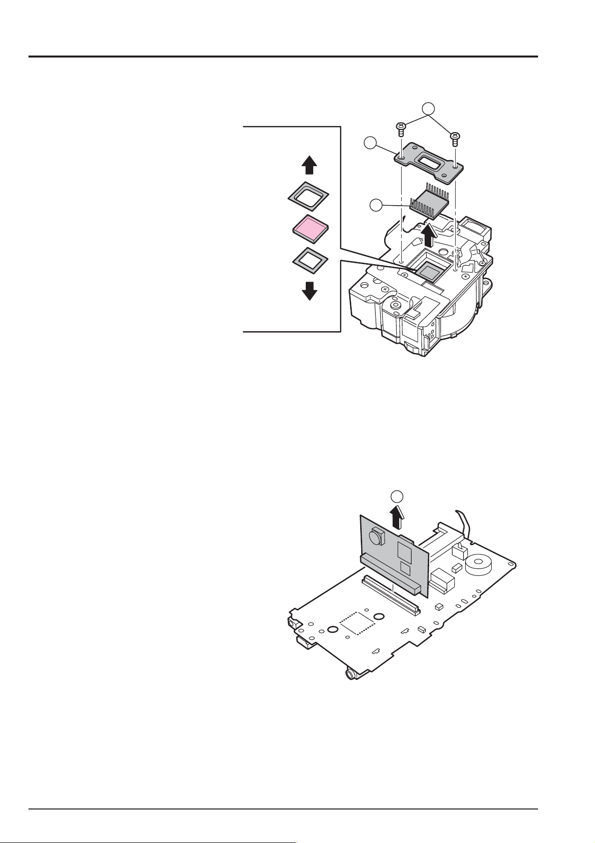
2-8. Method of disassembling LENS BLOCK
* Remove in the order indicated by circled numbers.
< Step 1 >
(1) Remove twoscrew.
(2) Remove CCD PLATE.
(3) Remove CCD.
LPF
RUBBER
OPTICAL
LPF
LPF
MASK
CCD
LENS UNIT
FinePix A330 SERVICE MANUAL
1
2
3
[ Assembly ]
(1) Assemble it in the reverse order of disassembling.
(2) Set the pink reflection side in CCD about O.LPF.
(3) Shake out the dust.
2-9. Removing ENGINE PWB ASSY
* Remove in the order indicated by circled numbers.
< Step 1 >
(1) Remove ENGINE PWB ASSY in the direction of the arrow.
1
[ Assembly ]
(1) Assemble it in the reverse order of disassembling.
(2) Note it in the direction of ENGINE PWB.
12

FinePix A330 SERVICE MANUAL
2. Disassembly
2-10. Removing BATTERY HOLDER ASSY
* Remove in the order indicated by circled numbers.
< Step 1 >
(1) Remove the hook, and remove
MAIN PLATE ASSY in the direction of the arrow.
(2) Remove one screw.
(3) Remove a fit of tripod, and remove the battery holder.
[ Assembly ]
(1) Assemble it in the reverse order of disassembling.
2-11. Removing LENS BARRIER
* Remove in the order indicated by circled numbers.
< Step 1 >
(1) Remove one screw.
* Note that the spring flies out.
(2) Remove one screw.
2
3
1
3
Fook
1
(3) Remove LENS BARRIER in the direction of the arrow.
* Remove in the place where the barrier was opened
2
Fook
3
[ Assembly ]
(1) Assemble it in the reverse order of disassembling.
13

2. Disassembly
<MEMO>
FinePix A330 SERVICE MANUAL
14

FinePix A330 SERVICE MANUAL
3. Schematic
3-1. Cautions
<Caution when replaceing chip (leadless) parts.>
* Do not re-use the removed parts, but use new parts.
Be careful that the negativ side of the tantalum capacitors are susceptible to heat.
* Voltage indications are omitted for capacitors other than chemical and tantalum capacitors
with a dielectric strength of 50 V or less.All units are uF (p shows pF).
* Chip resistors without indication are 1/10 W.
* k=1000
* Variable resistors and semi-variable resistor are abbreviated the specification of B characteristic.
3-2. Basic block name and function explanation
Board Name Block name Function
MAIN PWB MAIN BLOCK CCD output (IC101)
ENGINE PWB ENGINE BLOCK A/D conversion of CCD output (IC171), CCD driver (IC172),
RSW PWB RSW BLOCK Operating switches (SW/S1/S2)
LCD CONST LCD display
LENS CONST 3 x ZOOM LENS / IRIS 2 Steps
, M=1000 k
Shutter Iris, AF, zoom drive (IC501)
TG control (IC173), Flash Rom (IC204),
Image signal processing, system control, USB, LCD drive, DRAM (IC202),
Clock generator (IC203), VIDEO driver (IC206)
Power supply generation for loads, Flash control (IC301)
Operating switches ( U<->D / L<->R / OK<->CANCEL / CAM<->PB)
3. Schematic
15

3. Schematic
FinePix A330 SERVICE MANUAL
3-3.Functions of Primary Blocks
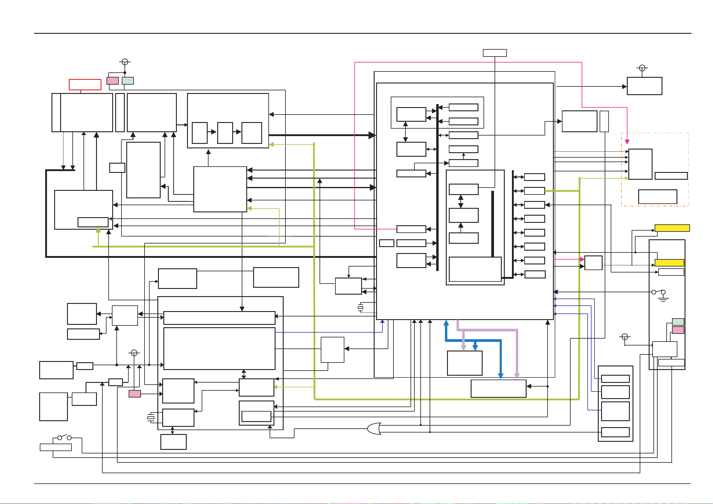
3-3-1.Technical Outline
The FinePix A303 incorporates a 1/2.7 -inch square pixel, primary color interline CCD of 3.34 million pixels(total).
An [xD picture card] is adopted as the recording media. ICs are the [AFE (IC171)] for CCD processing, [HPS IC
(IC301)] that incorporates power supply management capabilities into operation system processing, and system LSI
[XCS2 (IC202)] that pakeged signal processing, LCD drive, V-TG functions.
Video-out (NTSC/PAL) is added.
3-3-2.MAIN Board Block Functions
Photography Circuit Functions (MAIN BLOCK)
The analog video signal output from the CCD (1/2.7”, 3.34 million effective pixels,) is processed (pseudo-color
compensation, adaptive interpolation, amplification, and signal mixing) in AFE_IC (ENGINE PWB: IC171:CSP_IC),
and subsequently converted to a 12-bit digital signal. The digital signal is then sent to the single chip image signal
processing LSI : XCS2_IC (IC202 : CSP_IC*).
* CSP_IC=
3-3-3.ENGINE Board Block Functions
Image Signal Processing Functions (ENGINE BLOCK)
Data input from CCD
* The analog signals output by the CCD (1/2.7 square pixel, primary color interline CCD of 3.34 million pixels[total]
[IC101]) undergo color compensation, adaptive interpolation, amplification (ACG) and signal mixing in the
[AFE(IC171)] CCD signal processing IC. After that, the signals are converted into 12-bit digital signals and sent to the
[XCS2_IC (IC202)] system LSI. This block has a vertical drive IC (IC172) for driving the CCD.
* At the same time, AE multiplies the 12-bit image data input from the XCS2_IC in [AUTO], and sends the data required
for AE/AWB/AF to the SDRAM_area. To provide the appropriate data for AE/AWB/AF, this data is then sent from the
SDRAM_area in serial format to the AFE_IC via the XCS2_IC.
Recording in the xD media
The image data stored in the SDRAM_area is converted from 16-bit to 12-bit data one line at a time in the [IBUF] in the
XCS2_IC, and sent to [YC PRO]. The image data is then converted to 8-bit Y and C signals in [YC PRO], and then sent
again to [IBFC]. The 8-bit Y and C signals are then converted to 8-bit Y, Y, Cb, and Cr signals and sent to the
SDRAM_area. The image data stored in the SDRAM_area is compressed with [JPEG] in the XCS2_IC and again
stored in the SDRAM_area. The image data following compression is recorded sequentially in the xD media in the
XCS2_IC.
Image Replay from the xD media
The compressed image data from the xD media is sent to XCS2_IC, and stored in the SDRAM_area via [MEDIA]. The
compressed image data stored in the SDRAM_area is expanded with JPEG and stored again in the SDRAM_area.
The expanded image data is sent to [YC PRO] via [IBFC]. Gain control for the luminance and color difference signals,
and aperture processing, are performed in [YC PRO] and the image data then sent again to the SDRAM_area. The
image data is then displayed via [ENCD] and [D/A].
The photography adjustment data is stored in the FLASH_ROM (In the IC204). The FLASH_ROM also incorporates
firmware.
LCD Control Functions
The R, G, and B signals processed in the image signal processing XCS2_IC are output to the LCD panel via [LCD CONT].
A low-temperature polysilicon TFT color LCD monitor (1.5, 60,000 pixels) is used.
Chip Size Packege IC
Power Supply Functions
The power supply on the ENGINE board and MAIN board generates the -7.5V/15V (CCD), 1.5V (XCS2_IC), 3.3V
(AFE_IC/XCS2_IC/F_ROM/LED/KEY), MOT_5.0V (lens/flash), D_5V (AUDIO), LCD_13V (LCD backlight), D_3.3V
(LCD), and AD_3.3V (Video/ LCD) voltages.
16
FinePix A330 SERVICE MANUAL
p
(
)
p
A
_
A
A
D_3.3V
JTAG
LCD EVR*1
3. Schematic
3-4.BLOCK Diagram
D_5V
3xZOOM LENS
IRIS 2Steps
BARRIER
WIDE/TELE
Variable
LENS
Zoom position
Zoom HP
IC501
DC IN JACK
3.3V
BATT.
*R6
2
Special Batt DET
THERMISTOR
FINDER
Fo
PION
cus HP
Motor Drv..
M50239HP
6ch
CTL
X2_SIO
STRB-XE
STRB C
FUSE
Thermal
Protector
LED LED
IC101 BA-CCD
O.LPS
3.3millon pixels/
Cont.
Pulses
IC172
OFD
MD2174
IN1A,IN1B,IN1C,IN2A,IN2B,IN2C
VREF
STROBO
Block
STRB_UNREG
5V
FET
LED
SELF TIMER, Batt CHG
CHG_UNREG
,Illumination
X’TAL
FC-255
32..768kHz
1/2.7inch
V Drv.
SHT PULSE
MTR_CS
OFD_CONT
V
H
V Pulses
5V SW REG
5V
IC301
LED
DRIVER
3
RTC
BATT
Backu
IC171 RENESAS AFE
HD49340NP
3.3V Operation
CCDIN
CDS A/D C
IC173
PGA
RTG
FF1170
3.3V Operation
(Programmable)
HPS
AN30202
STROBOCTRL
DC/DC Block
D_3.3V
15V,-7.5V
DC_3.3V
SYS_3.3V
VRESET,OCO
VI,HI,ADCK
TG_CS
CAM_SIO
3.3V SRS REG
STRB_SY
CTL
Power on
Reset
NT
AD_3.3V
STRB_CHG
FE_CS
CCD[9-0]
CAM_SIO
CCDCLK
BATT_V
HPS_CS
PWSW
RESET
FCS_VCONT
VCLK_ON,CCD27_ON
27MHz
CCD
Voltage
Select
CLOCK
Generator
X’TAL
CX-53F
48.00MHz
CCD_VH(L)_SEL
PWON
24MHz
48MHz
_ACT
XCS2 SIP
IBFC
RECC
YCPRO
CGEN
EVR
Audio(A/D
A/D
JPEG
NT/PAL_SEL
24.545/24.375MHz
XCS2
3.3V Operation
DEBUG I/F
CPU Core
I-cache 4k
(MAX 48MHz)
128MB x16
AUTO
CCDIF
MEDIA
TFDC
ENCD
BUS Cont.
SDRAMC
DMAC
DDRESS BUS [11
DATA BUS [0-15]
SDRAM
IC204
NOR FLASH
M28W160CT
IC202
WDT
SIO
USB
MFT
ICU
ADC
PORT
CLKC
BEEP
xD Card
Slot
20PIN)
LCDDAT[7:0]
BL_ON,LCD,ON
LCDHD,LCD_VD,LCDCLK
LCD_CS
Vbus,D+,D-
V_DET
VBS_OUT
VIDEO_ON
RLDU
MODE
KEY4
X2_SIO
Video
Driver
MODE DIAL
(DISP)/FXP
DR_SW
CRD_DET
USER I/F
RLDU SW
7positions
OK/BACK
SW
CAM/PB
BUZZER
LCD
Cont.IC
DCDC
From DCDC
D_3.3V,AD_3.3V
in Multi
14
3.3V
D
LCD Panel
1.5inch
BL LED x2
VIDEO JACK
Cradle
VIDEO OUT
USB I/F
LED
LED
CHARGE
DC IN 3.3V
17
3. Schematic
)
A
p
3-5.Overall Connections
LENS BLOCK
VCOM
VGH
VC1
VC2
Vgnff_I
Vgnff_H
VC3
VC4
FRP
AVDD1
GND
DRV
FR(LED_C)
LED_A
VCC
AGND
AVDD
VSYNC
HSYNC
DCLK
DD5
DD4
DD3
DD2
DD1
DD0
SEL0
GBB
FinePix A330 SERVICE MANUAL
GND
VCC
TSCI
TSDA
CS
3xZOOM LENS
IRIS 2Steps
BARRIER
WIDE/TELE
Variable
LENS
IC101
BA-CCD
O.LPS
3.3millon pixels/
1/2.7inch
SW651
IC501
Motor Drv..
M50239HP
6ch
(KEY)
FLASH BLOCK
SW751
Batt DET
IC601
Video
Driver
IC172
V Drv.
MD2174
IC173
RTG
FF1170
3.3V Operation
(Programmable)
IC171
RENESAS AFE
3.3V Operation
CDS A/D C PGA
HD49340NP
IC204
FLASH ROM
M28W160CT
CLOCK
Generator
X’TAL
CX-53F
48.00MHz
48MHz
IC202
IBFC
YCPRO
Audio(A/D
A/D
NT/PAL_SEL
24.545/24.375MHz
RECC
CGEN
EVR
JPEG
(MAX 48MHz)
AUTO
CCDIF
MEDIA
TFDC
ENCD
DEBUG I/F
CPU Core
I-cache 4k
SDRAM
128MB x16
BUS Cont.
SDRAMC
DMAC
DDRESS BUS [11
DATA BUS [0-15]
NOR FLASH
M28W160CT
WDT
SIO
USB
MFT
ICU
ADC
PORT
CLKC
X’TAL
FC-255
32..768kHz
IC301
LED
DRIVER
RTC
BATT
Backu
AN30202
STROBOCTRL
DC/DC Block
D_3.3V
15V,-7.5V
DC_3.3V
SYS_3.3V
CTL
Power on
Reset
18
FinePix A330 SERVICE MANUAL
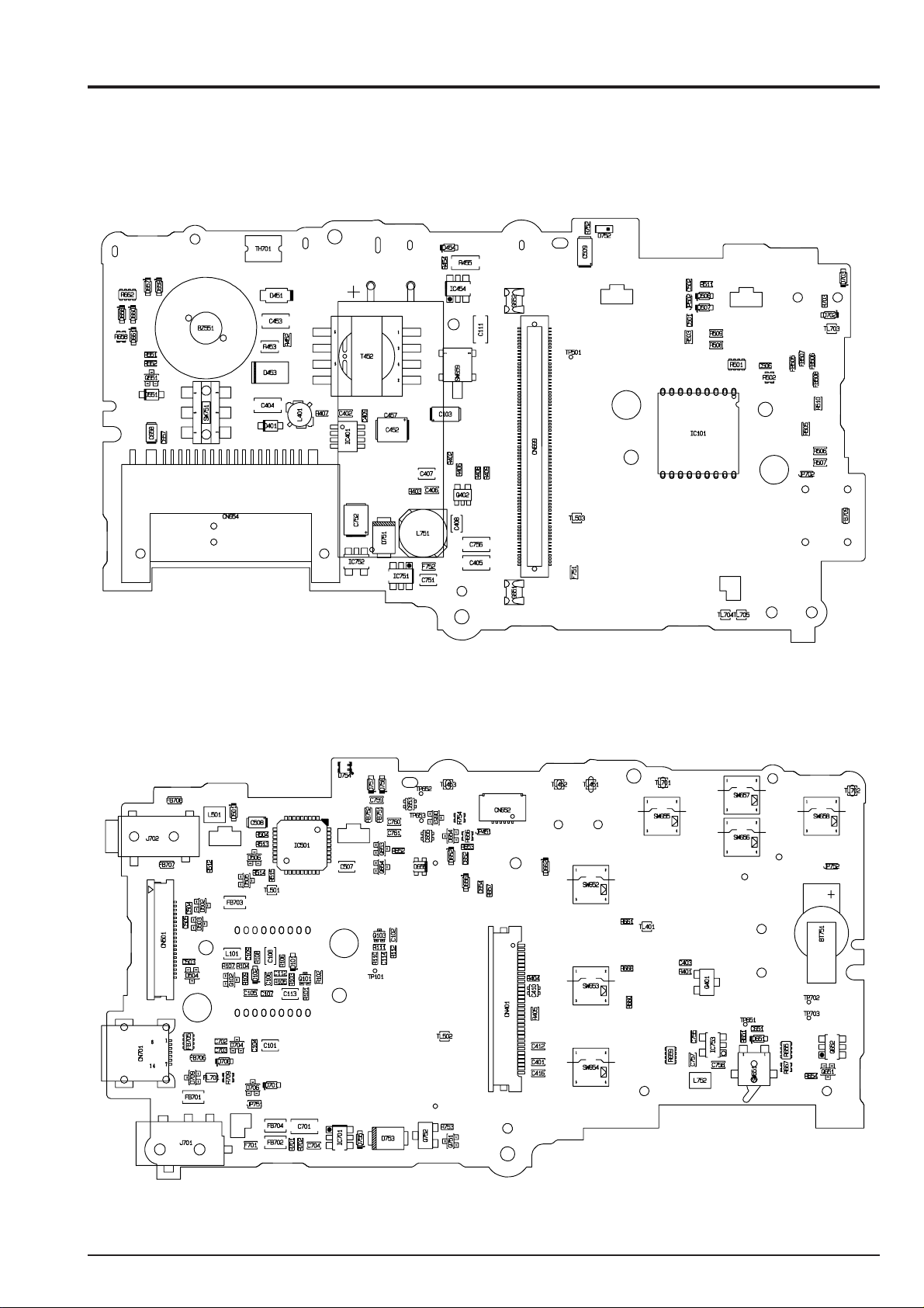
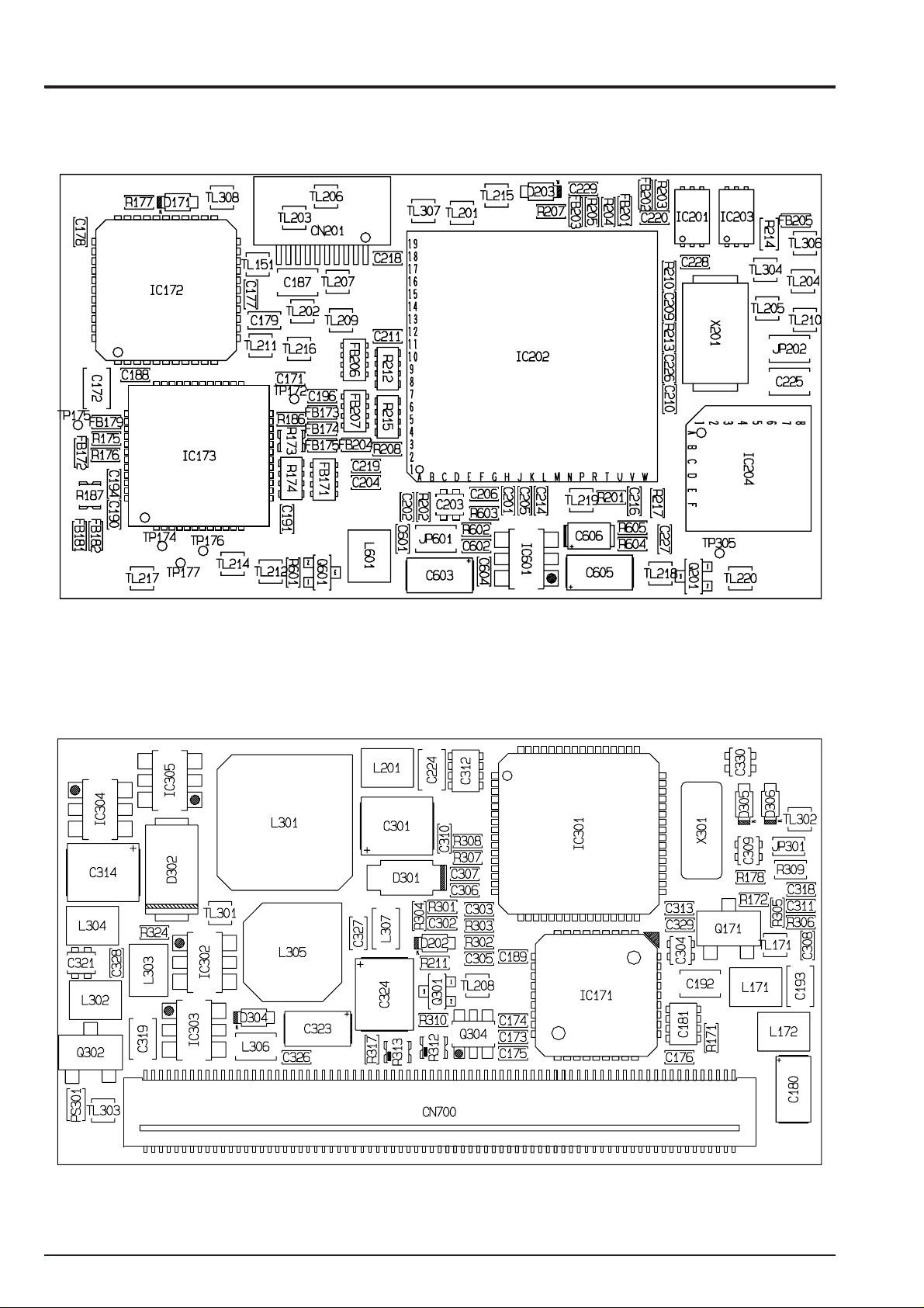
3-6. Board mounting diagram
3-6-1. Printed wiring board of MAIN PWB ASSY
< A side >
3. Schematic
< B side >
19
3. Schematic
3-6-2. Printed wiring board of ENGINE PWB ASSY
< A side >
FinePix A330 SERVICE MANUAL
< B side >
20
FinePix A330 SERVICE MANUAL
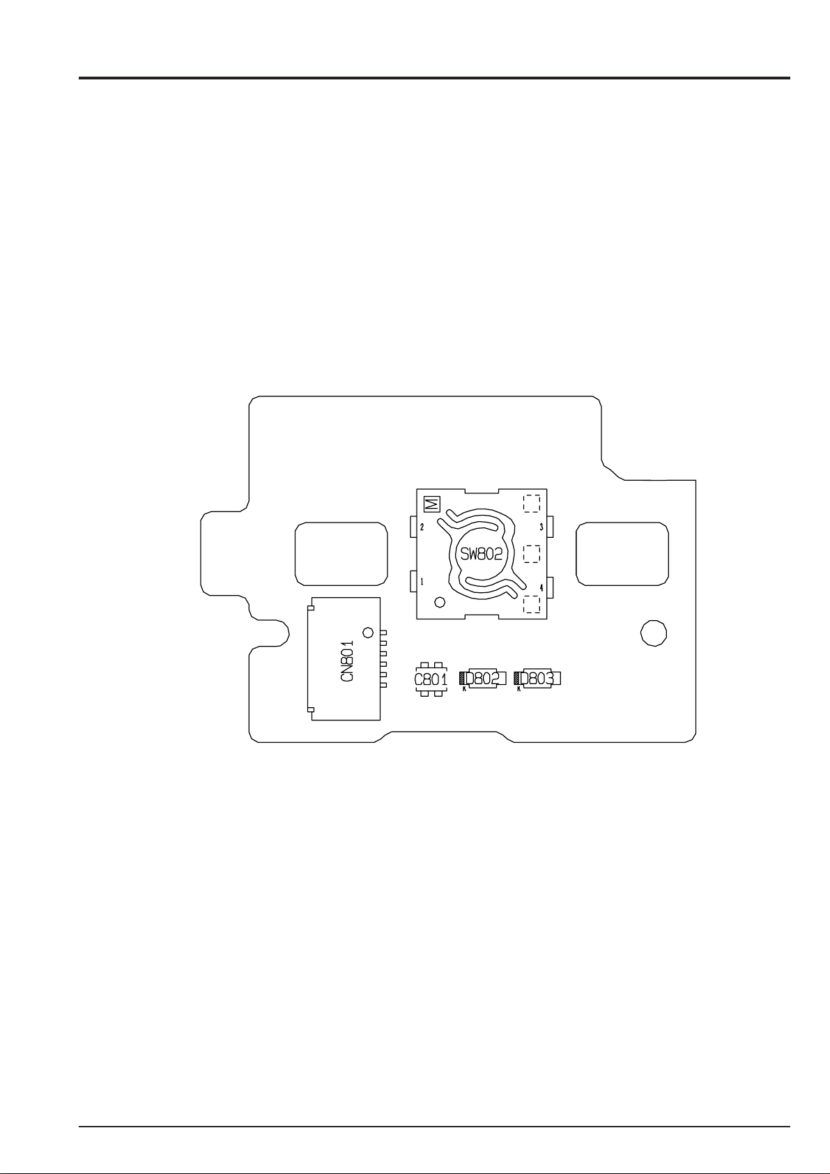
3-6-3. Printed wiring board of RSW PWB ASSY
3. Schematic
21
3. Schematic
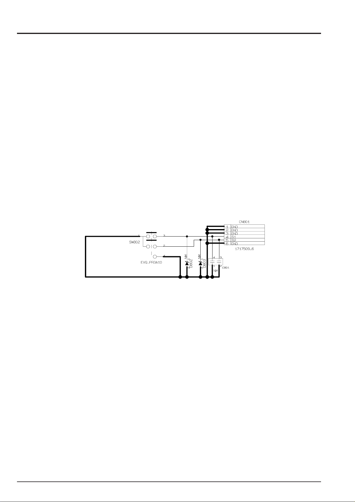
3-7.Circuit diagram
3-7-1. RSW BLOCK Circuit
FinePix A330 SERVICE MANUAL
22
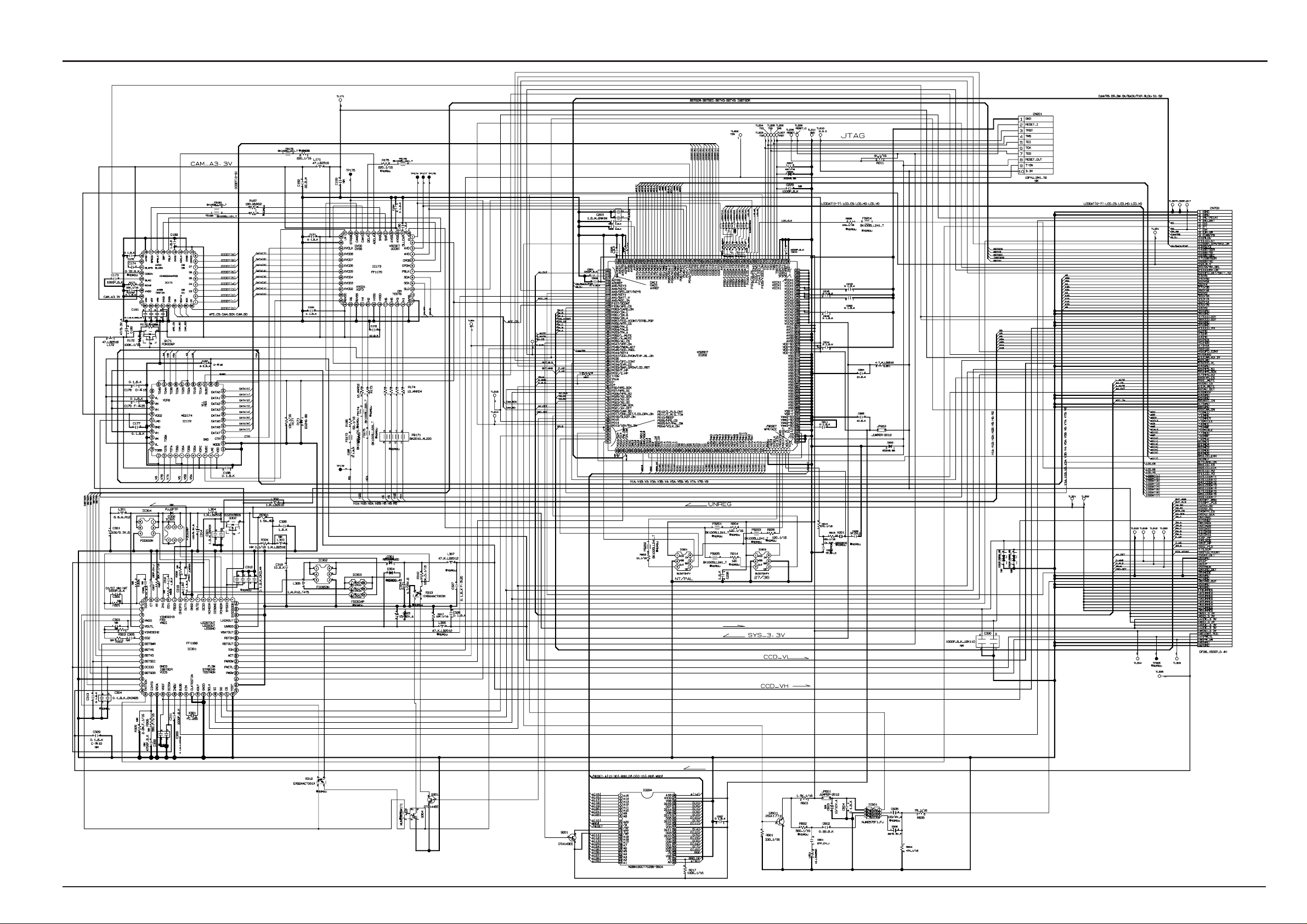
FinePix A330 SERVICE MANUAL
3. Schematic
3-7-2. ENGINE BLOCK Circuit
23
 Loading...