

FUJIFILM FinePix A310 SERVICE MANUAL
DIGITAL CAMERA
FinePix A310
SERVICE MANUAL
EG/EU/AS/US/CA/GE/CH/JP-Model
WARNING
THE COMPONENTS IDENTIFIED WITH THE MARK “ ” ON THE SCHEMATIC
DIAGRAM AND IN THE PARTS LIST ARE CRITICAL FOR SAFETY.
PLEASE REPLACE ONLY WITH THE COMPONENTS SPECIFIED ON THE SCHEMATIC
DIAGRAM AND IN THE PARTS LIST.
IF YOU USE PARTS NOT SPECIFIED, IT MAY RESULT IN A FIRE AND AN
ELECTRICAL SHOCK.
FUJI PHOTO FILM CO.,LTD.
Ref.No.:ZM00490-104
Printed in Japan 2005.05(S.S.)
SAFETY CHECK-OUT
After correcting the original problem, perform the following
safety check before return the product to the costomer.
FinePix A310 Service Manual
1. Check the area of your repair for unsoldered or poorly
sol dered connections. Check the entire board sur-
face for solder splasher and bridges.
2. Check the interboard wiring to ensure that no wires
are “pinched” or contact high-wattage resistors.
3. Look for unauthorized replacement parts, particuarly
tran sistors, that were installed during a previous re-
pair. Point them out to the customer and recommend
their replacement.
4. Look for parts which, though functioning, show ob-
vious signs of deterioration. Point them out to the
customer and recommend their replacement.
5. Check the B + voltage to see it is at the values speci-
fied.
6. Make leakage - current measurements to determine
that exposed parts are acceptably insulated from
the supply circuit before returning the product to the
customer.
7. CAUTION: FOR CONTINUED PRO-
TECTION AGAINST FIRE HAZARD,
REPLACE ONLY WITH SAME TYPE
2.5 AMPERES 125V FUSE.
2.5A 125V
2.5A 125V
RISK OF FIREREPLACE FUSE
AS MARKED
ATTENTION: AFIN D'ASSURER
UNEPROTECTION PERMANENTE
CONTRE LES RISQUES D'INCENDIE,
REMPLACER UNIQUEMENT PAR UN
FUSIBLE DE MEME, TYPE 2.5 AM-
PERES, 125 VOLTS.
8.
WARNING!
HIGH VOLTAGE
WARNING:
TO REDUCE THE ELECTRIC SHOCK,
BE CAREFUL TO TOUCH THE PARTS.
2

FinePix A310 Service Manual
TABLE OF CONTENTS
1.General ...................................... 4
1-1. Product specification ............................................ 4
1-2.Names of External Components ............................ 7
2. Disassembly ............................ 8
2-1. Internal Components ........................................... 8
2-2. Removing the R PANEL ASSY ............................. 9
2-3. Removing the LCD UNIT ................................... 10
2-4. Removing the MAIN PWB ASSY ........................ 10
2-5. Removing the BATTERY LID ............................... 11
2-6. Removing the Lens Unit ...................................... 11
2-7. Removing the Inner Cabinet Assy ....................... 12
2-8. Removing the SW PWB Assy ............................. 12
2-9. Removing the LINK Assy ................................... 13
2-10. Removing CCD PWB Assy .............................. 13
3. Schematics ............................ 14
3-1. Cautions ........................................................... 14
3-2. Basic Block Names and Functions ...................... 14
3-3.Functions of Primary Blocks. ............................... 15
3-3-1.Technical Outline.................................... 15
3-3-2.Functions of Individual Blocks ............. 15
3-4. Block Diagram .................................................. 16
3-5. Overall connection Diagram ............................... 17
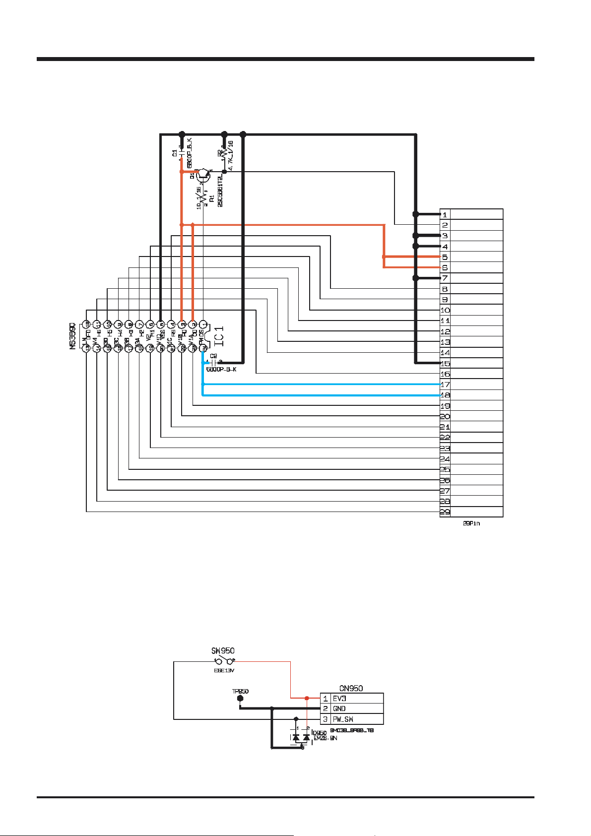
3-6. CCD BLOCK Schematic Diagram ....................... 18
3-7. POWER SW BLOCK Schematic Diagram ........... 18
3-8. CAMERA BLOCK Schematic Diagram ................ 19
3-9. PROCESS BLOCK Schematic Diagram ............. 20
3-10. POWER BLOCK Schematic Diagram ............... 21
3-11. VIDEO BLOCK Schematic Diagram .................. 22
3-12. KEY IC BLOCK Schematic Diagram ................. 23
3-13. KEY SW BLOCK Schematic Diagram ............... 24
3-14. R SW BLOCK Schematic Diagram ................... 24
3-15. MOTOR BLOCK Schematic Diagram ................ 25
3-16. LCD BLOCK Schematic Diagram ..................... 26
3-17. FLASH BLOCK Schematic Diagram ................. 27
3-18. MAIN PWB ASSY Component Locations .......... 28
3-19. SUB PWB ASSY Component Locations ............ 28
4. Adjustments........................... 29
4-1. Adjustment Procedure of Parts Replacement ....... 29
4-2. Measuring Devices ............................................ 29
4-3. Jigs .................................................................. 29
4-4. Jig Connections ................................................. 30
4-5. Environment Setup ............................................ 30
4-6. Installing the Jig Drivers on the PC ...................... 31
4-7. Installing and Starting the Adjustment Software ..... 32
4-8. Initializing the Adjustment Software ...................... 32
4-9. Starting the Adjustment Software ......................... 35
4-10. [F4] : CCD data input ....................................... 38
4-11. [F5] : Camera adjustment ................................. 40
4-12. [F6] : AF adjustment ......................................... 43
4-13. [F7] : Flash adjustment ..................................... 45
4-14. [F11] : VIDEO Adjustment ................................. 47
4-15. [F1] : Battery voltage adjustment ....................... 49
4-16. [F8] : Firmware Download ................................ 52
4-17. [F12] : End Setting ........................................... 54
5. Inspection .............................. 58
5-1. Required Measuring Equipment ......................... 58
5-2. Connection of Measuring Equipment ................... 58
5-3. Inspection and Factory Settings .......................... 58
6.Parts List ................................. 60
6-1.Packing and Accessories .................................... 60
6-1-1.For EG model .......................................... 60
6-1-2.For EU model .......................................... 61
6-1-3.For AS model .......................................... 62
6-1-4.For US model .......................................... 63
6-1-5.For CA model .......................................... 64
6-1-6.For GE model .......................................... 65
6-1-7.For CH model .......................................... 6 6
6-1-8.For JP model...........................................67
6-2.Cabinet F block .................................................. 68
6-3.Main PWB block ................................................ 69
6-4.Cabinet R block .................................................. 70
6-4-1.For EG/EU/AS/US/CA/GE/CH model ......... 70
6-4-2.For JP model ........................................... 71
6-5.Electrical parts .................................................... 72
7. Appendix ................................ 73
7-1.List of Related Technical Updates Issued .............. 73
3
1.General
FinePix A310 Service Manual
1.General
1-1. Product specification
System
Model Digital camera FinePix A310
Number of effective pixels
CCD sensor 1/2.7 inch Super CCD HR in an interwoven pattern
Number of recorded pixels
Storage media xD-Picture Card (16/32/64/128/256 MB)
File format Still image: JPEG (Exif ver. 2.2)
Lens Fujinon 3× optical zoom lens Aperture: F2.8 to F4.8
Aperture F2.8 to F4.8/F7.0 to F11.6 (automatically selected)
Focus distance f=5.7 mm to 17.1 mm (Equivalent to 38 mm to 114 mm on a 35 mm camera)
Focal range Normal: Approx. 60 cm (2.0 ft.) to infinity
Shutter speed 2 sec. to 1/2000 sec. (depend on Exposure mode)
Focus TTL contrast-type, Auto focus
Sensitivity
Photometry TTL 64-zones metering
Exposure control AUTO (Program AE/Manual (with exposure correction))
Exposure compensation
White balance Auto Manual modes, 7 positions can be selected
Viewfinder Real image optical Approx. 80% coverage
LCD monitor 1.5-inches, 60,000-pixel Amorphous silicon TFT, Approx. 92% coverage
Flash Auto flash using flash control sensor
Self-Timer 10 sec.
Video output NTSC/PAL selectable
3.1 million pixels
Number of total pixels 3.14 million pixels
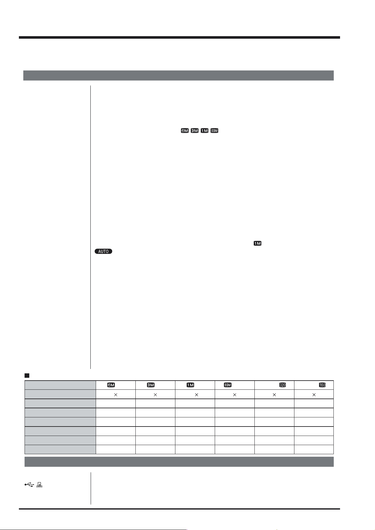
Still image: 2816 × 2120 pixels/2048 × 1536 pixels/1280 × 960 pixels/
640 × 480 pixels (
/ / / )
Movie: 320 × 240 pixels (10 frames per second without sound)
160 × 120 pixels (10 frames per second without sound)
* Design rule for Camera File System compliant DPOF compatible
Movie: AVI format, Motion JPEG
Macro: Approx. 10 cm (3.9 in.) to 80 cm (2.6 ft.)
Manual: Equivalent to ISO200/400/800 (Image quality fixed at for shots taken at ISO 800.)
: Equivalent to ISO160-400 (at LCD on and Flash off)
-2.1 EV to +1.5 EV in 1/3-step increments (in Manual mode)
Effective range: Wide-angle: Approx. 0.3 m-5.0 m (1.0 ft.-16.4 ft.)
(Approx. 0.3 m-0.8 m (1.0 ft.-2.6 ft.): Macro)
Telephoto-angle: Approx. 0.3 m-4.0 m (1.0 ft.-13.1 ft.)
Flash modes: Auto, Red-Eye Reduction, Forced Flash, Suppressed Flash, Slow
Synchro, Red-Eye Reduction + Slow Synchro
Standard number of available shots/recording time per xD-Picture Card
Quality
Number of recorded pixels
Image Data Size
DPC-16 (16 MB)
DPC-32 (32 MB)
DPC-64 (64 MB)
DPC-128 (128 MB)
DPC-256 (256 MB)
6M
2816 2120
1.5 MB
10
21
43
86
173
3M
2048 1536
780 KB
19
40
81
162
325
1M
1280 960
470 KB
33
68
137
275
550
640 480
130 KB
Input/Output Terminals
Video output socket mini-jack
(USB) socket For file transfer to a computer and connection to the optional cradle
DC Input Socket for specified AC power adapter AC-3V (optional)
Connection for the AC Power Adapter AC-3VW bundled with the cradle (sold separately)
4
0.3M
122
247
497
997
1997
Movie
320 240
–
Approx. 98 sec.
Approx. 199 sec.
Approx. 6.6 min.
Approx. 13.3 min.
Approx. 26.7 min.
Movie
160 120
–
Approx. 5.6 min.
Approx. 11.3 min.
Approx. 22.7 min.
Approx. 45.5 min.
Approx. 91.2 min.

FinePix A310 Service Manual
Power Supply and Others
Power supply Use one of the following
• 2AA-size alkaline batteries
• 2AA-size Ni-MH (Nickel-Metal Hydride) batteries (optional)
• Rechargeable Battery NH-10 (optional)
• AC-3VW (PictureCradle CP-FXA10, Sold separately)
• AC Power Adapter AC-3V (optional)
1.General
Number of available
shots using battery
(battery life)
(Condition: Power saving mode ON, with fully charged battery (Ni-MH))
This indicates the number of available frames shot consecutively at room temperature with a flash use rate of 50%. Note that these figures may vary depending on the
ambient temperature and the amount of charge in the battery. The number of avail-
able shots or available shooting time will be lower in cold conditions.
Conditions for use Temperature: 0
Camera dimensions 97.0 mm × 63.9 mm × 33.0 mm/3.8 in. × 2.5 in. × 1.3 in.
(W/H/D) (not including accessories and attachments)
Camera mass (weight)
Weight for photography
Accessories ! 16 MB, xD-Picture Card (1) Included with: Anti-static case (1)
Optional Accessories ! xD-Picture Card
Approx. 155 g/5.5 oz. (not including accessories, batteries and xD-Picture Card)
Approx. 210 g/7.4 oz. (including batteries and xD-Picture Card)
! LR6 AA-size alkaline Batteries (2)
! Strap (1) !
! Cradle adapter for FinePix A310 (1)
! USB Interface Set (1)
• CD-ROM: Software for FinePix SX (1)
• Special USB cable with Noise Suppression core (1)
• Quick start guide for Camera and Software installation (1)
! Owner’s Manual (1)
! AC Power Adapter AC-3V ! Fujifilm Rechargeable Battery 2HR-3UF
! Fujifilm Battery charger with Battery BK-NH (With Euro type or UK type plug)
! PictureCradle CP-FXA10 ! Rechargeable Battery NH-10
! SC-FXA01
! DPC-R1 Image Memory Card Reader
! DPC-AD PC Card Adapter
! CompactFlash Card Adapter
Battery Type With LCD monitor ON With LCD monitor OFF
Alkaline batteries Approx. 160 frames Approx. 250 frames
Ni-MH batteries 1700 mAh Approx. 250 frames Approx. 350 frames
Rechargeable Battery
NH-10
o
C to +40oC (+32oF to +104oF); 80% humidity or less (no condensation)
Special video cable 2.5 mm dia. mini plug-to-pin plug Approx. 1.5 m (1)
DPC-16 (16 MB)/DPC-32 (32 MB)/DPC-64 (64 MB)/DPC-128 (128 MB)/DPC256 (256 MB)
• Compatible with Windows 98/98 SE, Windows Me, Windows 2000 Professional, Windows XP or iMac, Mac OS 8.6 to 9.2, Mac OS X (10.1.2 to 10.2.2)
and models that support USB as standard.
• Compatible with xD-Picture Card of 16 MB to 256 MB, and SmartMedia of
3.3V, 4 MB to 128 MB.
• Compatible with xD-Picture Card of 16 MB to 256 MB, and SmartMedia of
3.3V, 2 MB to 128 MB.
• Windows 95/98/98 SE/Me/2000 Professional/XP
• Mac OS 8.6 to 9.2/X (10.1.2 to 10.1.5)
Approx. 280 frames Approx. 400 frames
5

1.General
FinePix A310 Service Manual
Explanation of Terms
Deactivated batteries: Leaving an Ni-MH battery unused in storage for a long period may cause a rise in
the level of substances that inhibit current flow inside the battery and result in a
dormant battery. A battery in this state is referred to as deactivated.
Because current flow is inhibited in a deactivated Ni-MH battery, the battery’s original level of performance cannot be achieved.
DPOF: Digital Print Order Format
DPOF is a format used for recording information on a storage media (image memory
card, etc.) that allows you to specify which of the frames shot using a digital camera
are printed and how many prints are made of each image.
EV: A number that denotes Exposure Value. The EV is determined by the brightness of
the subject and sensitivity (speed) of the film or CCD. The number is larger for
bright subjects and smaller for dark subjects. As the brightness of the subject changes,
a digital camera maintains the amount of light hitting the CCD at a constant level by
adjusting the aperture and shutter speed.
When the amount of light striking the CCD doubles, the EV increases by 1. Likewise, when the light is halved, the EV decreases by 1.
Frame rate (fps): The frame rate is a unit used to indicate the number of images (frames) played back
per second. This camera shoots movie files at 10 consecutive frames per second, a
rate that is expressed as 10 fps. By comparison, TV images are played at 30 fps.
JPEG: Joint Photographics Experts Group
A file format used for compressing and saving color images. The compression ratio
can be selected, but the higher the compression ratio, the poorer the quality of the
expanded image.
Memory effect: If an Ni-MH battery is repeatedly charged without first being fully discharged, its
performance may drop below its original level. This is referred to as the “memory
effect”.
Motion JPEG: A type of AVI (Audio Video Interleave) file format that handles images and sound as
a single file. Images in the file are recorded in JPEG format. Motion JPEG can be
played back by QuickTime 3.0 or later.
PC Card: A generic term for cards that meet the PC Card Standard.
PC Card Standard: A standard for PC cards determined by the PCMCIA.
PCMCIA: Personal Computer Memory Card International Association (US).
White Balance: Whatever the kind of the light, the human eye adapts to it so that a white object still
looks white. On the other hand, devices such as digital cameras see a white subject
as white by first adjusting the color balance to suit the color of the ambient light
around the subject. This adjustment is called matching the white balance. A function
that automatically matches the white balance is called an Automatic White Balance
function.
Exif Print: Exif Print Format is a newly revised digital camera file format that contains a variety
of shooting information for optimal printing.
6
FinePix A310 Service Manual
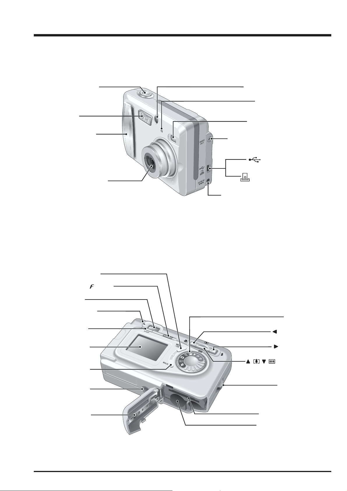
1-2.Names of External Components
1.General
Shutter button
Flash
Power switch
Lens (Lens cover)
Flash control sensor
Self-timer lamp
Viewfinder Window
VIDEO OUT (Video output)
socket
(USB) socket
Cradle connection
socket
DC IN 3V (power input) socket
MENU/OK button
Photo mode ( ) button
Viewfinder
Viewfinder lamp
DISP button
LCD monitor
BACK button
Tripod mount
Battery cover
Mode dial
Macro button
Flash button
( ) ( )/Zoom switch
Strap mount
xD-Picture Card slot
Battery compartment
7
2. Disassembly
2. Disassembly
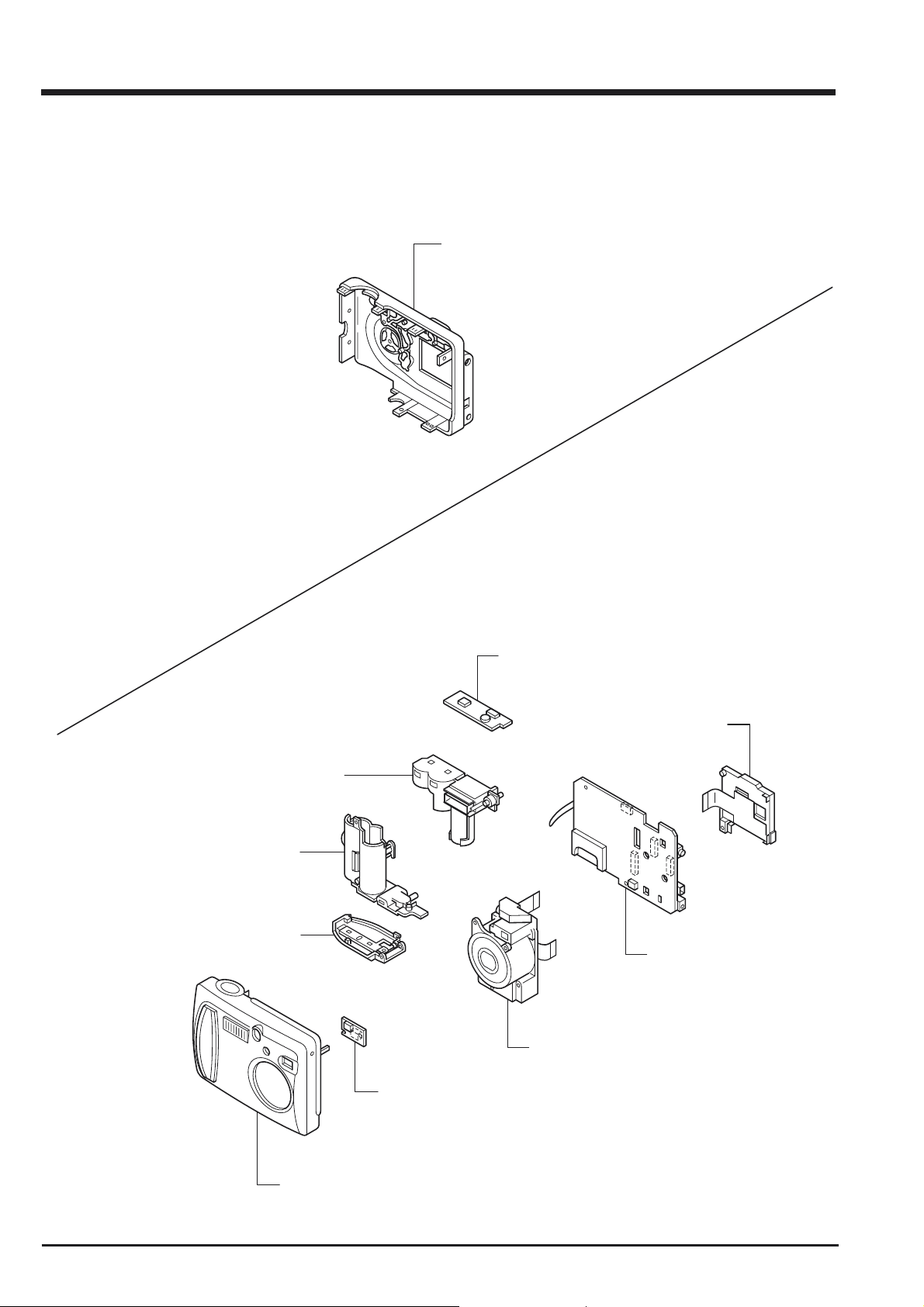
2-1. Internal Components
FinePix A310 Service Manual
CABINET REAR ASSY
FLASH UNIT
BATTERY HOLDER
BATTERY LID
SUB PWB ASSY
LCD UNIT
MAIN PWB ASSY
LENS UNIT
PSW PWB ASSY
CABINET FRONT ASSY
8
FinePix A310 Service Manual
1
1
1
2
3
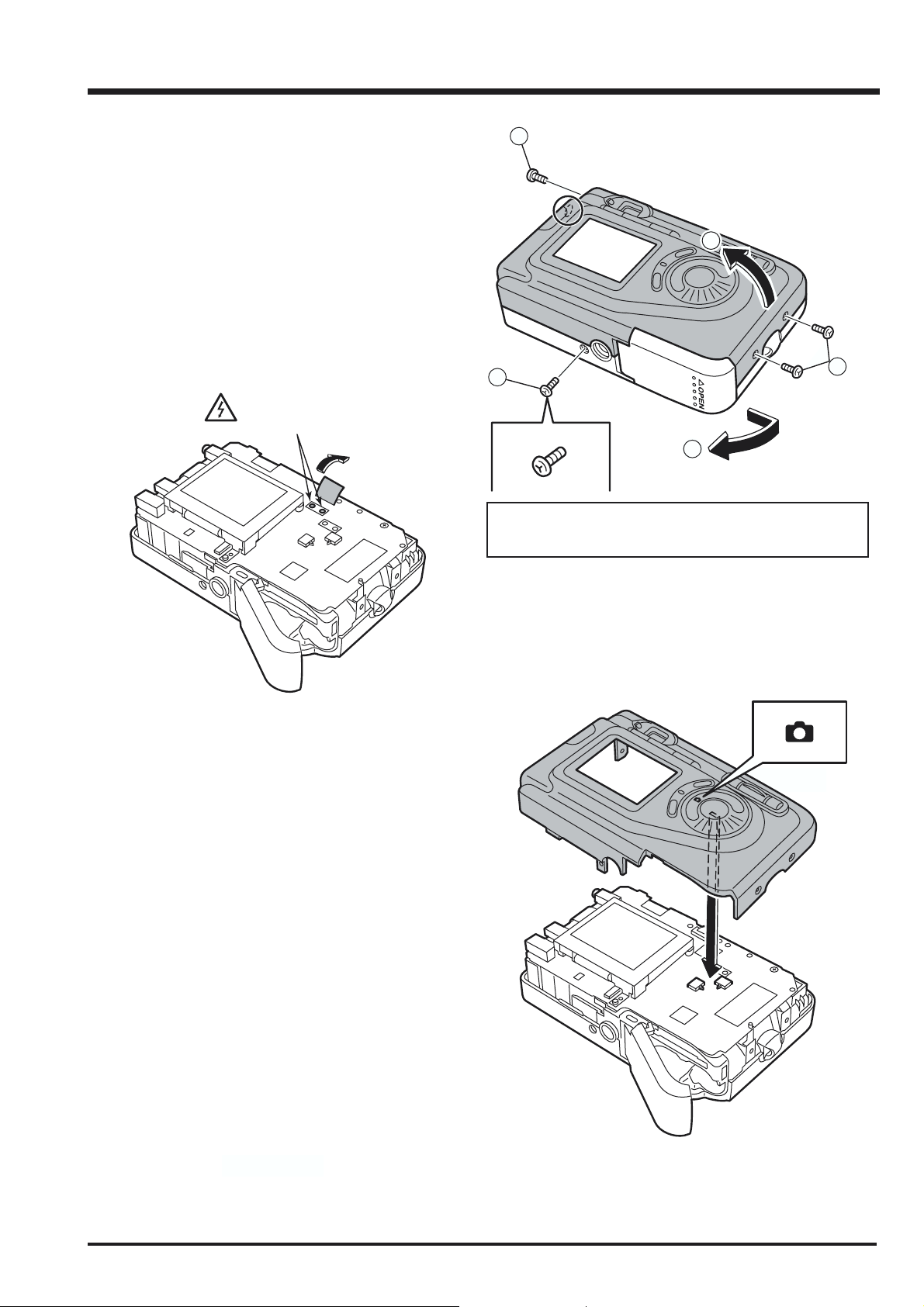
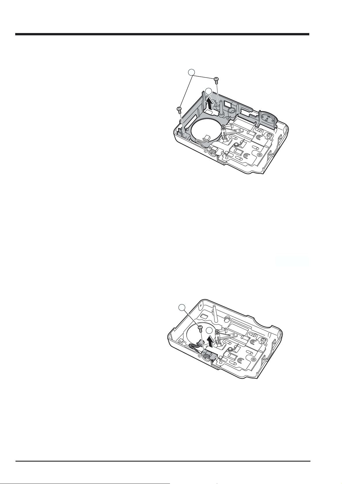
2-2. Removing the R PANEL ASSY
[Disassembly]
1. Remove the four screws(M1.7x5).
2. Open the battery cover.
3. Raise the R PANEL ASSY in the direction of the
arrow.
Note:
Always ensure that the FLASH ASSY main condenser is
discharged before beginning disassembly.
Discharge point
2. Disassembly
Screw of special shape.
Use the screw driver of jig number(ZJ00583-100)
[Assembly]
Set the mode dial to the camera position and assemble it.
Assemble in the reverse order to disassembly.
9
2. Disassembly
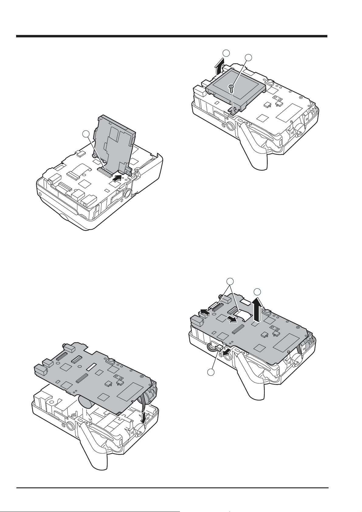
2-3. Removing the LCD UNIT
[Disassembly]
1. Remove the screw(M1.7x5).
2. Raise the LCD UNIT in the direction of the arrow.
3. Remove the connector.
3
FinePix A310 Service Manual
2
1
2-4. Removing the MAIN PWB ASSY
[Disassembly]
1. Remove the FFC.
2. Remove the NAIN PWB in the direction of the
arrow taking care not caught of the shutter button.
[Assembly]
Assemble in the reverse order to disassembly.
1
3
2
10
[Assembly]
Put it in the space so as not to bend the thermistor.
FinePix A310 Service Manual
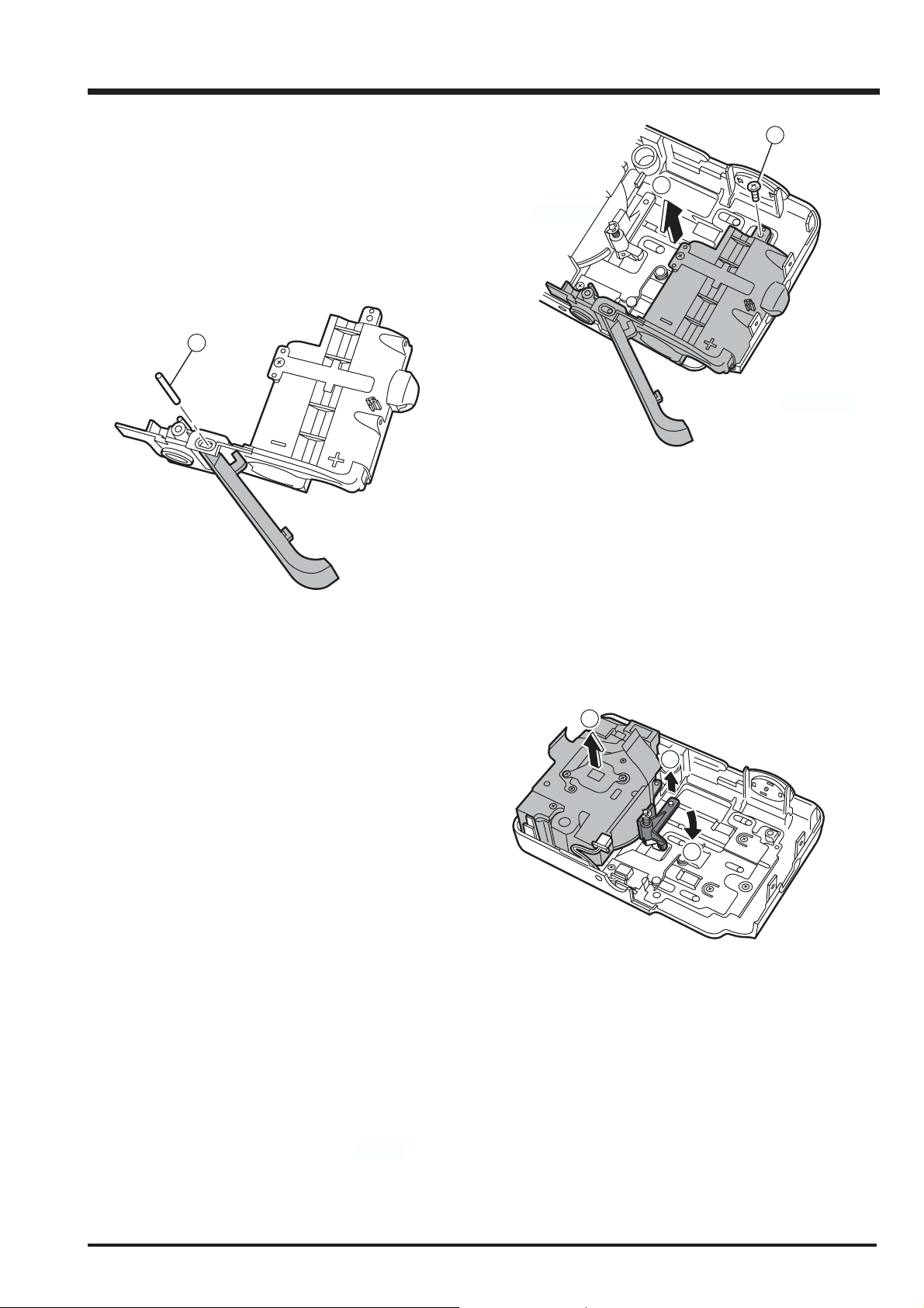
2-5. Removing the BATTERY LID
[Disassembly]
1. Remove the screw(M1.7x5).
2. Remove the BATTERY HOLDER in the direction of
the arrow.
3. Remove the BATTERY SHAFT.
3
2. Disassembly
1
2
[Assembly]
Assemble in the reverse order to disassembly.
2-6. Removing the Lens Unit
[Disassembly]
1. Move the barrier stopper in the direction of the
arrow 1&2.
3. Remove the Lens Unit in the direction of the arrow.
3
1
2
[Assembly]
Assemble in the reverse order to disassembly.
11
2. Disassembly
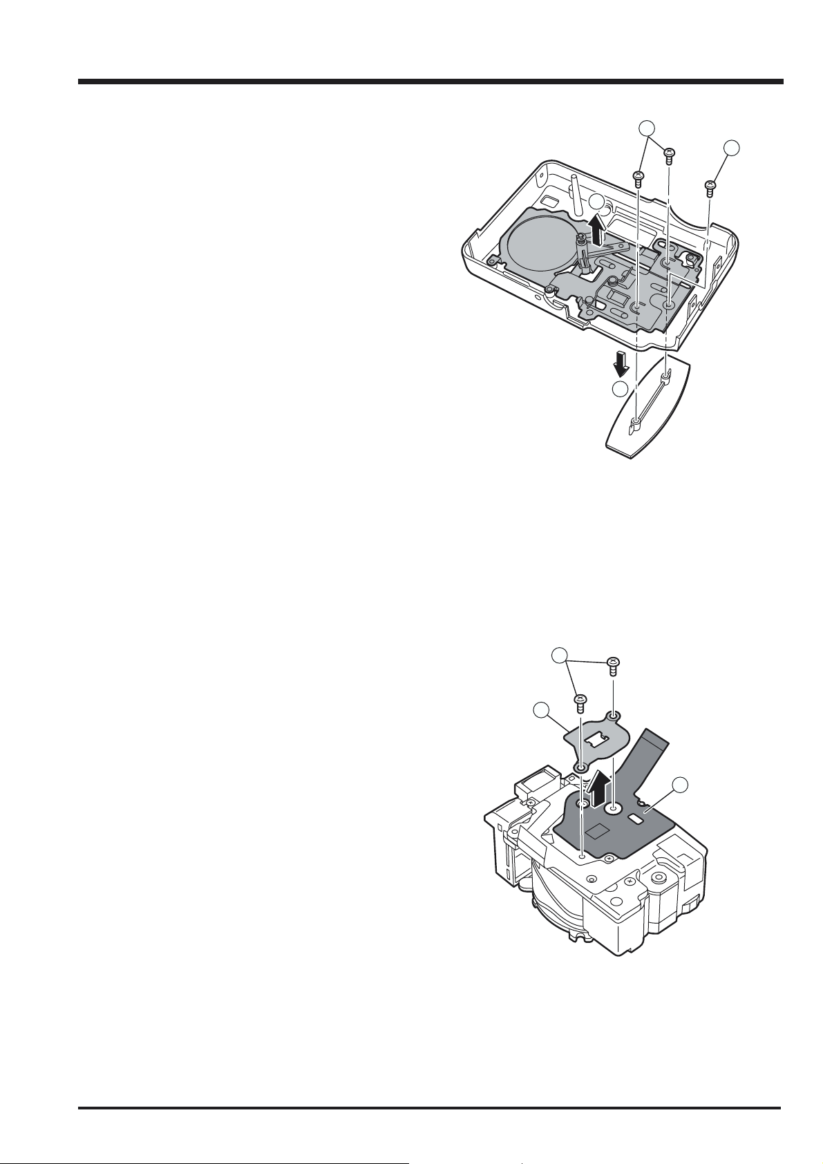
2-7. Removing the Inner Cabinet Assy
FinePix A310 Service Manual
[Disassembly]
1. Remove the two screws(M1.7x3.5 ).
2. Remove the Inner Cabinet Assy in the direction of
the arrow.
1
2
[Assembly]
Assemble in the reverse order to disassembly.
2-8. Removing the SW PWB Assy
[Disassembly]
1. Remove the screw(M1.7x3.5 ).
2. Remove in the SW PWB Assy direction of the
arrow
1
2
12
[Assembly]
Assemble in the reverse order to disassembly.
FinePix A310 Service Manual
2-9. Removing the LINK Assy
[Disassembly]
1. Remove two screws (M1.7x3.5). andRemove the
Grip parts in the direction of the arrow.
2. Remove the screw(M1.7x3.5).
3. Remove the LINK Assy in the direction of the arrow.
2. Disassembly
1
2
3
1
2-10. Removing CCD PWB Assy
[Disassembly]
1. Remove two screws (M1.7x3.0). and
2. Remove the CCD PLATE .
3. Remove the CCD PWB Assy in the direction of the
arrow.
[Assembly]
Assemble in the reverse order to disassembly.
1
2
3
[Assembly]
Assemble in the reverse order to disassembly.
13

3. Schematics
FinePix A310 Service Manual
3. Schematics
3-1. Cautions
<Cautions when replacing parts>
• Do not reuse removed parts. Always use new parts.
• Note that the -ve side of tantalum condensers is readily damaged by heat.
• Except for chemical condensers and tantalum condensers, voltage is not displayed on condensers with a voltage
resistance of 50V or less.
• Resistors not marked are 1/16W chip resistors.
• KW = 1000Ω, MW = 1000KΩ
• B characteristics of variable resistors and semi-fixed resistors are not displayed.
3-2. Basic Block Names and Functions
Part name Block name Function
LENS CONST CCD BLOCK CCD output
MAIN PWB ASSY CAMERA BLOCK CCD output A/D conversion (IC102)
CCD driver ( IC101)
PROCESS BLOCK Image signal processing, USB communications,
system control (IC203)
MOTOR BLOCK Shutter/iris/AF/zoom drive (IC651)
KEY BLOCK Power supply management ,Key function(IC401)
LCD BLOCK LCD output.
DC/DC BLOCK Power supply generation (IC301,IC302)
FLASH BLOCK Flash charging control (IC601)
SUB PWB ASSY RSW BLOCK Power SW,Shutter SW,Backup battery
FLASH UNIT FLASH BLOCK Flash
14

FinePix A310 Service Manual
3-3.Functions of Primary Blocks.
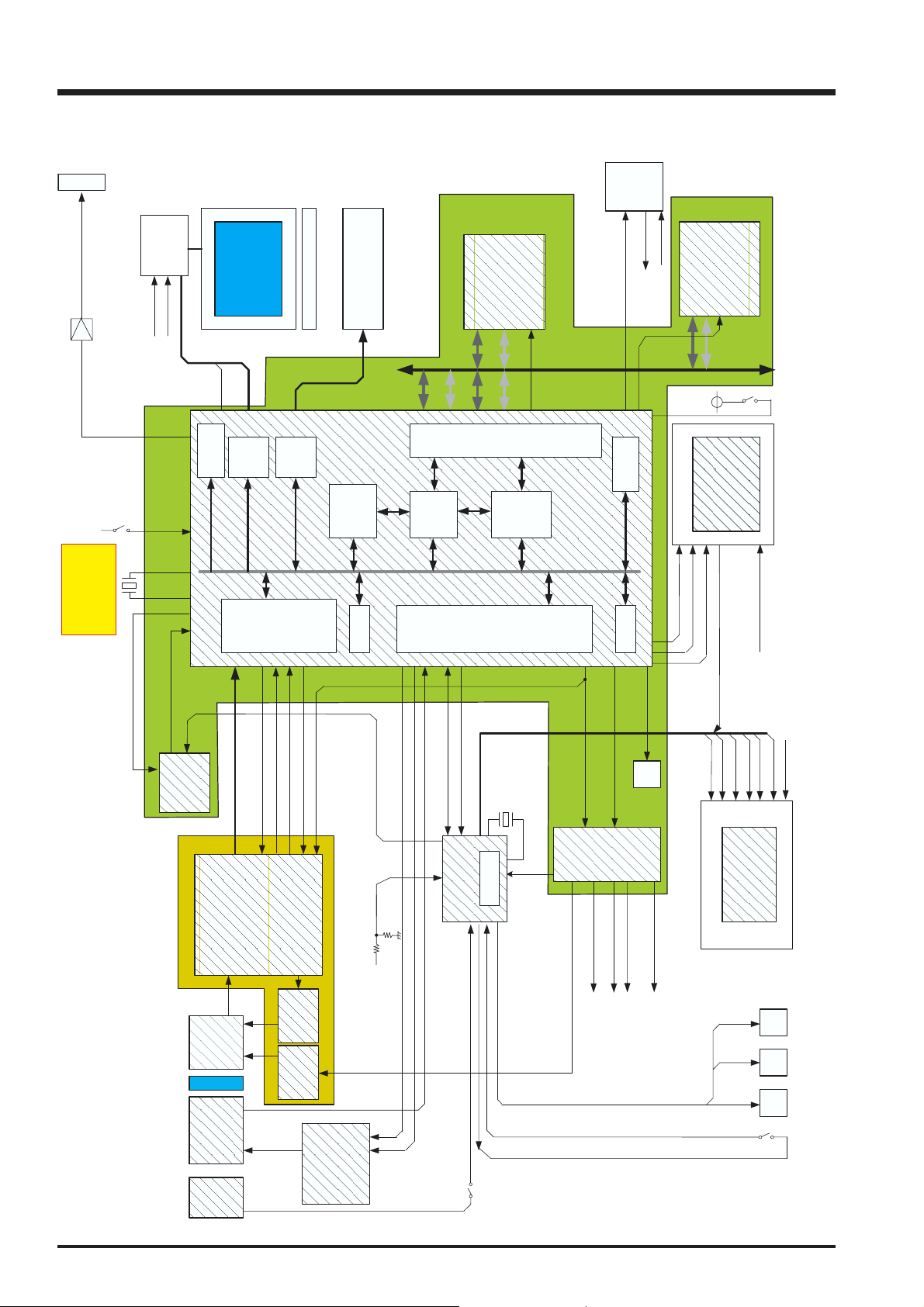
3-3-1.Technical Outline
The FinePix A310 incorporates a 1/2.7 inch Fourth Generation Super CCD HR sensor with 3.1 million effective pixels.
An [xD picture card] is adopted as the recording media.
New ICs are the [ACS2 (IC102)] for CCD processing, [KEY IC (IC400)] that incorporates power management capabilities into
operation system IC, and system LSI [XCS (IC203)]that packaged signal processing, LCD drive, TG functions and DRAM.
The flash light block is modularized.
The camera is internally capable of discharge function for the rechargable battery (NH-10).
The camera is internally capable of charging the rechargable battery (NH-10) when used with the Picture Cradle CP-FXA10.
The camera incorporated a thermistor to monitor temperature during internal charging the battery(NH-10) for safety.
3-3-2.Functions of Individual Blocks
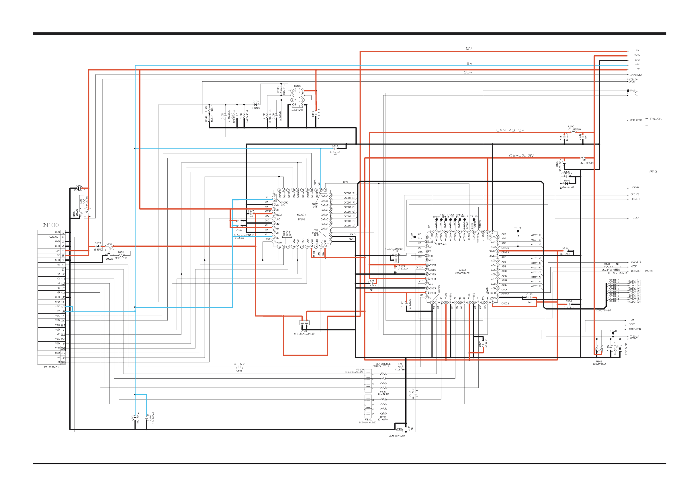
(1) CCD Signal Processing/Picture-taking Blocks (CCD BLOCK and CAMERA BLOCK)
The analog signals output by the CCD (1/2.7 inch Fourth Generation Super CCD HR sensor with 3.1 million effective pixels
[IC1]) undergo color compensation, adaptive interpolation, amplification (ACG) and signal mixing in the [ACS2 (IC102)] CCD
signal processing IC. After that, the signals are converted into 10-bit digital signals and sent to the system LSI [XCS (IC203)].
This block has a vertical drive IC (IC101) for driving the CCD.
(2) Motor Block (MOTOR BLOCK)
Upon receiving commands from operating switches, the [XCS (IC203)] signal processing LSI manages the motor drive IC
(IC651) so as to control the motors for AF, shutter, zoom and iris.
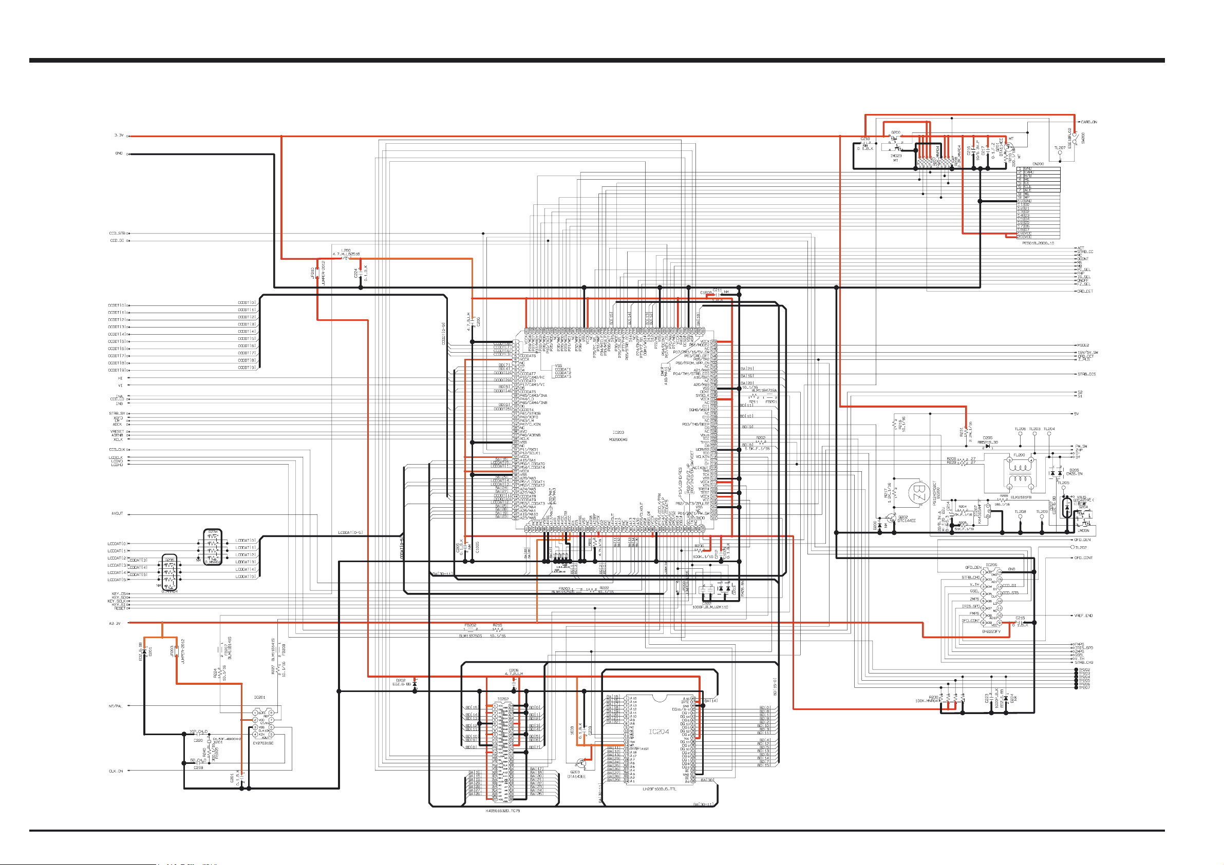
(3) Image Signal Processing Block (PROCESS BLOCK)
Input Data from the CCD
The 10-bit digital image data (equivalent to 1H) output by the image unit (CCD/CAMERA BLOCK) is sent to the system LSI [XCS
(IC203)]. It is here converted into 16-bit data by the internal buffer of the LSI, and image data of 2816 x 2120 pix per frame is
temporarily stored in the [IC202 DRAM (256 Mbit)] of the LSI.
Also, the 10-bit image data input to this LSI is used for calculations by the [auto calculation unit] and sent to the [ACS2 (IC102)]
CCD processing IC of the CAMERA BLOCK so as to obtain a suitable AE, AWB and AF.
3. Schematics
Recording to the xD picture card
The image data stored in the [IC202 DRAM (256 Mbit)] of the system LSI [XCS (IC203)] is sent to the signal processing block
one line at a time where it undergoes unpack processing (processing required prior to digital clamping, ( compensation, 10-bit >>
8-bit R/G/B conversion) and YC processing (8-bit digital R/G/B signal >> Y:Cb:Cr = 4:2:2). The 8-bit Y/Cb/Cr data is then sent to
the [internal buffer]. In the [internal buffer], data is arranged in a format that is easy to convert the 8-bit Y/Cb/Cr data into DCT.
After going through the [JPEG calculation unit] and the [media controller], it is recorded on the xD card.
Play back from the xD picture card
The compressed image data from the xD card is sent to the [XCS (IC203)] system LSI as 8-bit image data. It is then sent to the
[media control unit] >> [DMA unit] >> [IC202 DRAM (256 Mbit)] >> [media controller] >> [JPEG calculation unit] >> [signal
processing unit]. The [signal processing unit] does the post-processing of converting the 8-bit Y/Cb/Cr signals into 8-bit R/G/B
signals. At the same time, it weighs the text display signal and displays the text on the LCD UNIT via the [LCD controller].
Camera system adjustment data is stored in the FLASH ROM (IC204).
(4) LCD UNIT
The digital signal sent from the system LSI [XCS (IC203)] is sent to the drive IC of the LCD UNIT via the processing unit on the
LCD FPC of the LCD UNIT, where [LCD drive] and [LCD panel tonal control] are performed.
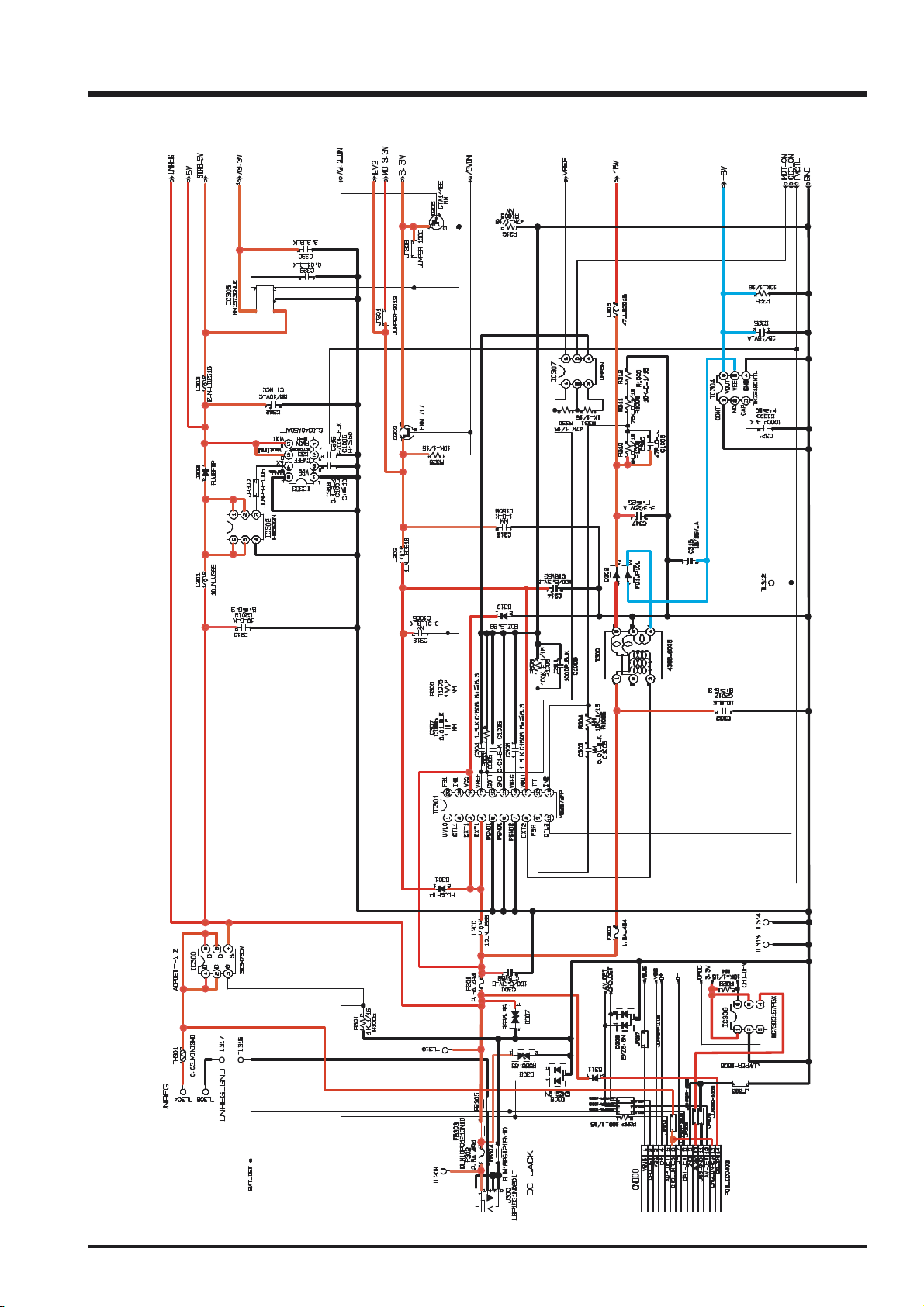
(5) Power Supply Block (DCDC BLOCK)
The power supply block is built around the DC IC (IC301). It generates the below power supplies and supplies them to the
individual blocks.
3.3 V [XCS (IC203), ACS2 (IC102), V-Drv (IC101), EVR (IC206), FLASH ROM (IC204), STRB IC (IC601),
MOTOR Drv (IC651), KEY IC (IC400), xD Picture Card, MAIN PWB, SUB PWB]
5V [V-Drv(IC101,MOTOR Drv(IC651)]
EV3 [Key(IC400),MAIN_PWB, SUB_PWB,PSW_PWB]
A3.3V [XCS (IC203), CLK GEN (IC201), MAIN PWB, LCD]
STRB 5V [STRB IC (IC601)]
16 V [CCD (IC1), OFD(IC100),V Drv (IC101)]
-8 V [CCD (IC1), V Drv (IC101)]
UNREG [STRB Block, KEY IC Block]
15
3. Schematics
3-4. Block Diagram
FinePix A310 Service Manual
A
V
DR_SW
MURATA
48.00MHz
FZ04887-100
CSTCW48M0X11066-R0
X 201 OSC
LCD BLK
LCD_BR
LCD_CONT
from EVR
IC203
MITSUBISHI 3.3V
LCD
LCDHD
LCDCLK
VIDEO
XCS
LCDVD
AU
[7:0]
LCDDATA
IBUF
A015AN02
LCD
BL LED
MEDIA
Removable MEDIA
Core
CPU
JPEG
Serial
SEL
Memory
Ctrl
IC204
SAMSUNG
FLASH ROM
2MByte
Local
BUS
M28W160CT_70ZB6
Memory
Ctrl
Multi
Connector
CHG_UNREG
TRON
D+, D-, VBUS,
for DC
USB
M32906FP PARTX
TIMER
OFD_DEN
From CAM
STRB_DIS
IC202
DRAM
256MBit x16
3.3V
IC601
CTL IC
FLASH BLK
STRB_FULL
STRB_CC
STRB_SY
SAMSUNG
K4S561632E_TLTI
S1/S2/MODE2
NEC
UPC5023GR_178_8J
GSEL, V_TH, STRB_CHG
from EVR
PROCESS BLOCK
SYSCLK
24.54545MHz/24.375MHz
IC201
CY27031
Generator
CLK
CAMERA BLOCK
O
CYPRESS
ACS2
CCDOUT
IC1
CCD
LPF
LENS
x3 ZOOM
LENS
CCDDT[9:0]
FFM
MS3890
Barrier
OCONT,ADENB
HI, VI, ADCLK,FI
IC102
TG_SY
V Drv
OFD
CCDLD,LM
SI, SO, SCLK
MD2174
IC101IC100
NJM2143
MotorDrv
IC651
MITSUBISHI
NT/PAL_SW
BAT_V
M50233HP
KEY_SIO
KEY_STB
ROHM
FF1152
KEY
ZHP,FHP,ZPLS
INA,INB,IS_SEL
MA,MB,MC,PI_SEL,FZ_SEL,ONOFF
OFD
FZ04859-100
EPSON MC-306
32.768KHz Xtal
RTC
IC 400 3.3V
PW_SW
X 400
VREF_END
SIO,SCLK
EVR
EVR_LD
IC206
10ch
STRB_CHG
GSEL, V_TH
to FLASH
BEEP
ROHM
BH2223FV
LCD_CONT
LCD_BR_UNI,
IRIS_SPD, FMPS,ZMPS
to LCD
to MOTOR Drv
KO0,KO1,KO2,KO3
KI0,KI1,KI2
BL_ON
LCD_ON
DC BLK
F_LON
CARD_ON
MOTOR_ON
DC/DC IC
Z_LON
CHG_UNREG
ST
LED
B
LED
R
LED
from
CONNECTOR
U/D/L/R
FXM/DISP
EXE/CAN/MODE1
16
FinePix A310 Service Manual
PW PWB
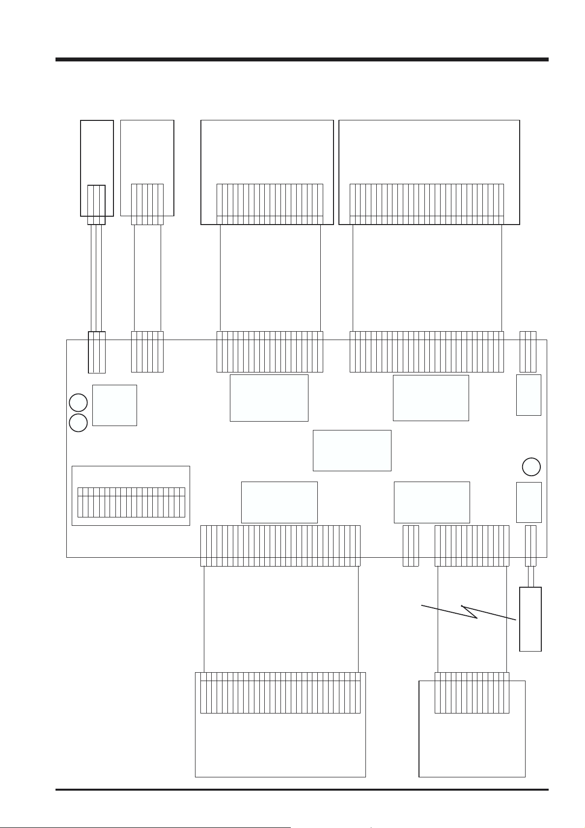
3-5. Overall connection Diagram
3. Schematics
PW PWB
PW_SW
CN950
PW_SW
GND
EV3
3
1
22GND 17D6
WIRE 15 D4
1
3
CN400
PW_SW
EV3
LED
KEY
RSW
GND 6 6 GND 10 GND
5
FFC
5
RSW
PWB
K02 1 1 K02 5 CE
S2 2 2 S2 U/D/L/R_SW 6 CLE
S1 3 3 S1 OK/CANCEL/DISP_SW 7 ALE
4 4 MODE1/MODE2/FXM 8 WE
CN900
CN500
LENS UNIT
SHUTOUT1+ 11 11 SHUTOUT1+ AGND1 18 18 AGND1
SHUTOUT2- 12 12 SHUTOUT2- SHDB 19 19 SHDB
LED_3.3V 16 16 LED_3.3V FR 23 23 FR
ZPOSI_E 15 15 ZPOSI_E SHI 22 22 SHI
ZPOSI_C 17 17 ZPOSI_C DRV 24 24 DRV
IRIS2+ 14 14 IRIS2+ STB 21 21 STB
ZM_1+ 19 19 ZM_1+ FAP 26 26 FAP
ZM_2- 20 20 ZM_2- VGH 27 27 VGH
FH19S_20S_0.5SH VGI 28 28 VGI
IRIS1- 13 13 IRIS1- VCC 20 20 VCC
GND 18 18 GND COM 25 25 COM
FPC FPC
MOTOR
LED_3.3V 9 9 LED_3.3V VLED- 16 16 VLED-
ZPI_E 10 10 ZPI_E VLED+ 17 17 VLED+
ZPI_C 8 8 ZPI_C AVDD 15 15 AVDD
FM_B 7 7 FM_B HSYNC 14 14 HSYNC
FM_A 6 6 FM_A VSYNC 13 13 VSYNC
FM/B 5 5 FM/B DCLK 12 12 DCLK
CCDFPC
LED3.3V 1 1 LED3.3V DS2 8 8 DS2
FPI_C 3 3 FPI_C DS4 10 10 DS4
FPI_E 2 2 FPI_E DS3 9 9 DS3
FM/A 4 4 FM/A DS5 11 11 DS5
LM 29 29 LM AVDD1 2 2 AVDD1
V8 28 28 V8 AGND1 1 1 AGND1
V3A 22 22 V3A
V3B 23 23 V3B
V2 21 21 V2
V4 24 24 V4
V5 25 25 V5
V6 26 26 V6
V7 27 27 V7
V1A 19 19 V1A JACK_GND 3
V1B 20 20 V1B XE00635
-8V 18 18 -8V ADPT_SW 2 DC_JACK
-8V 17 17 -8V
GND 15 15 GND
OFD 16 16 OFD
H3 11 11 H3 ADP_DET 12 12 ADP_DET
H4 12 12 H4 DC_IN 13 13 DC_IN
H5 13 13 H5 DC_IN 14 14 DC_IN
H6 14 14 H6 55768_1491
RS 8 8 RS GND 9 9 GND
H1 9 9 H1 3.3V 10 10 3.3V
H2 10 10 H2 USB_GND 11 11 USB_GND
CN650
CAM
GND 7 7 GND GND 8 8 GND
16V 6 6 16V D- 7 7 D-
CCD_OUT 2 2 CCD_OUT PWCTRL 3 3 PWCTRL
GND 3 3 GND D+ 4 4 D+
GND 4 4 GND BAT_DET 5 5 BAT_DET
16V 5 5 16V CHG_UNREG 6 6 CHG_UNREG
GND 1 1 GND CRD_DET 2 2 CRD_DET
CN100
1VBS XE+
2AV_DET XE-
3 AV_GND
LGK1709_1641C
J453
VIDEO
MAIN_PWB
FLE
SEL
20 VCC
19 VCC
PRO
SENSOR
CN200
16 D5
18 D7
11 D0
12 D1
13 D2
14 D3
9
WP
CARD
1GND
2CARD
3 R/B
RE4
00_6292_030_000
GND 30 30 GND
VCC 29 29 VCC
LCD
DC
CN550
GND 3 3 GND
GRB 5 5 GRB
DS0 6 6 DS0
DS1 7 7 DS1
U/D 4 4 U/D
JACK_UNREG
J300
1
FLASH
CN300
VBIS 1 1 VBIS
XE_TUBE
FPC
LCD UNIT
CRADL
E
17
3. Schematics
3-6. CCD BLOCK Schematic Diagram
FinePix A310 Service Manual
NM
CN1
GND
CCD_OUT
GND
GND
16V
16V
GND
RS
H1
H2
H3
H4
H5
H6
GND
OFD
-8V
-8V
V1A
V1B
V1C
V1D
V2
V3A
V3B
V3C
V3D
V4
LM
3-7. POWER SW BLOCK Schematic Diagram
18
FinePix A310 Service Manual
3-8. CAMERA BLOCK Schematic Diagram
3. Schematics
19
3. Schematics
3-9. PROCESS BLOCK Schematic Diagram
FinePix A310 Service Manual
20
FinePix A310 Service Manual
3-10. POWER BLOCK Schematic Diagram
3. Schematics
21
3. Schematics
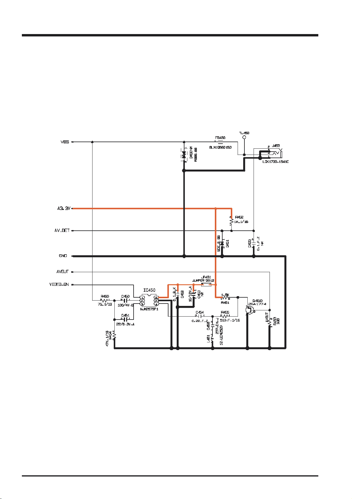
3-11. VIDEO BLOCK Schematic Diagram
FinePix A310 Service Manual
22
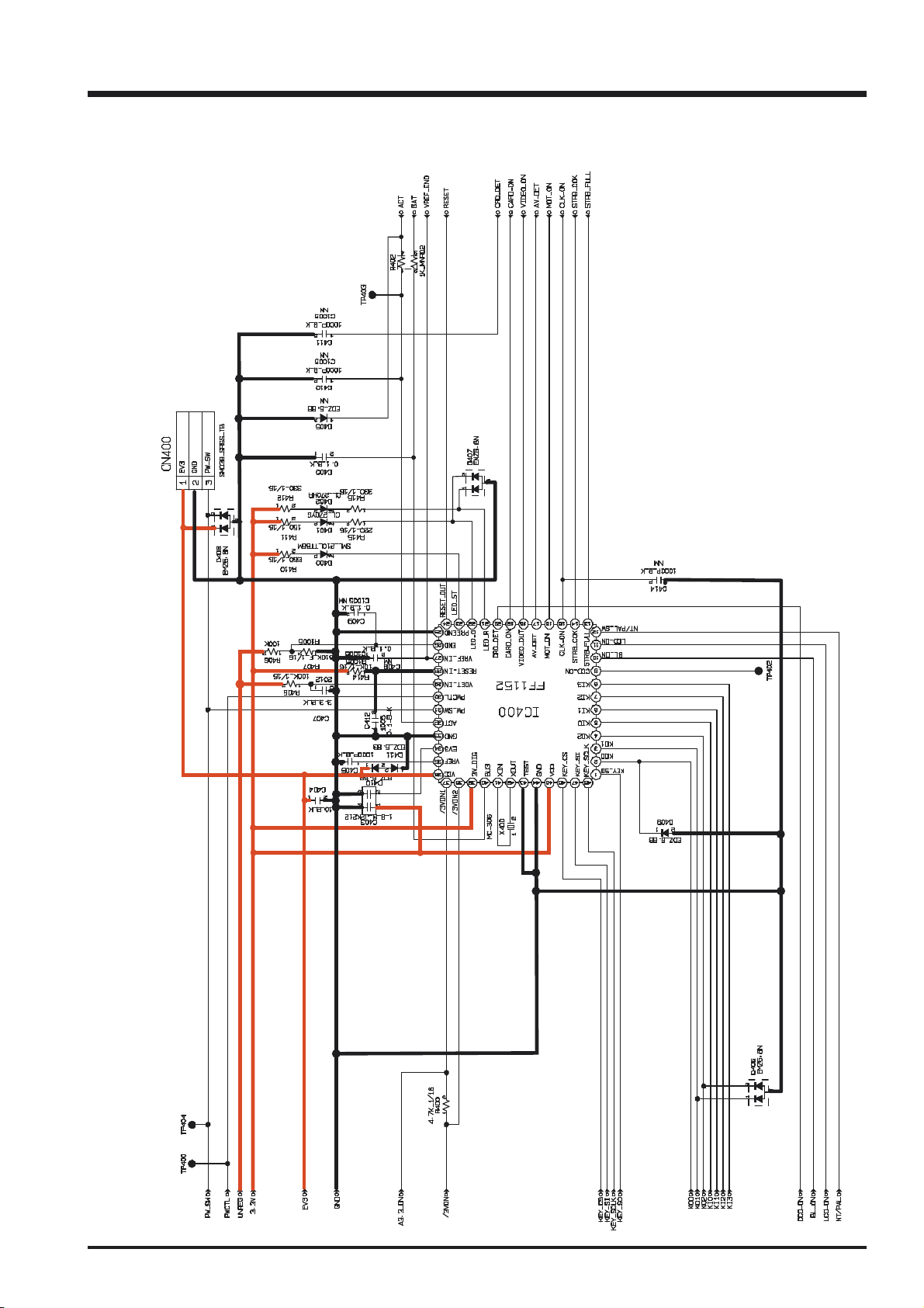
FinePix A310 Service Manual
3-12. KEY IC BLOCK Schematic Diagram
3. Schematics
23
 Loading...