

Page 1
DIGITAL CAMERA
FinePix A310
TROUBLESHOOTING GUIDE
US/EU/EG/CA/GE/AS-Model
WARNING
THE COMPORNENTS IDENTIFIED BY THE MARK “ ” ON THE SCHEMATHIC
DIAGRAM AND IN THE PARTS LIST ARE CRITICAL FOR SAFETY.
PLEASE REPLACE ONLY BY THE COMPONENTS SPECIFIED ON THE SCHEMATHIC
DIAGRAM AND IN THE PARTS LIST.
IF YOU USE WITH PART NUMBER UN-SPECIFIED, IT MAY RESULT IN A FIRE AND AN
ELECTORICAL SHOCK.
FUJI PHOTO FILM CO.,LTD.
Ref.No.:ZM00490-400
Printed in Japan 2003.12(S.S.)
Page 2
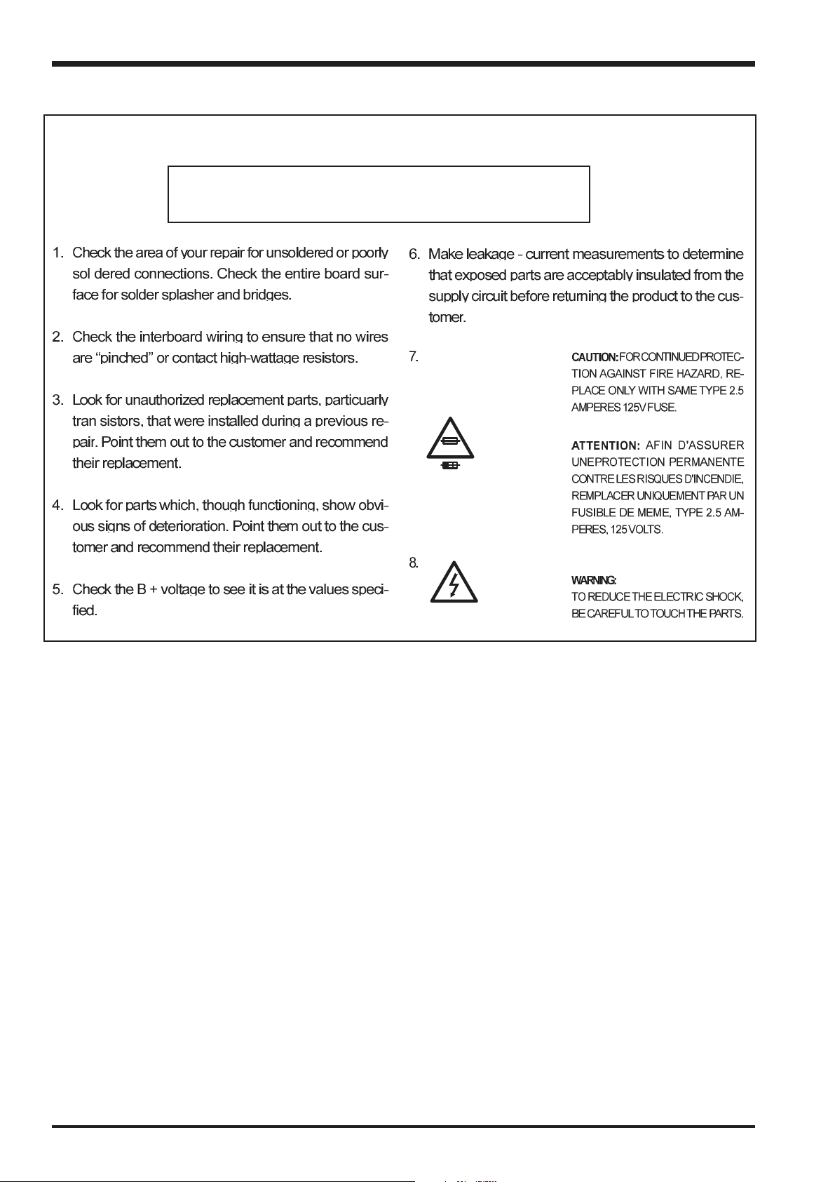
SAFETY CHECK-OUT
After correcting the original problem, perform the following
safety check before return the product to the costomer.
FinePix A310 TROUBLESHOOTING GUIDE
2.5A 125V
2.5A 125V
RISK OF FIREREPLACE FUSE
AS MARKED
WARNING!
HIGH VOLTAGE
2
Page 3

FinePix A310 TROUBLESHOOTING GUIDE
TABLE OF CONTENTS
1. Power-related ...........................................................................................4
1-1 Power 1 ............................................................................................................................................... 4
1-2 Power 2 ............................................................................................................................................... 4
1-3 Power 3 ............................................................................................................................................... 5
1-4 Power 4 ............................................................................................................................................... 5
1-5 Power 5 ............................................................................................................................................... 5
1-6 Power 6 ............................................................................................................................................... 6
1-7 Power 7 ............................................................................................................................................... 6
1-8 Power 8 ............................................................................................................................................... 7
2. Image-related ............................................................................................ 7
2-1 Image 1................................................................................................................................................ 7
2-2 Image 2................................................................................................................................................ 8
2-3 Image 3................................................................................................................................................ 9
2-4 Image 4................................................................................................................................................ 9
2-5 Image 5...............................................................................................................................................10
3. LCD-related .............................................................................................10
3-1 LCD 1 .................................................................................................................................................. 10
3-2 LCD 2 .................................................................................................................................................. 11
3-3 LCD 3 .................................................................................................................................................. 11
3-4 LCD 4 .................................................................................................................................................. 12
4. Switch-related .........................................................................................12
4-1 Switch 1 ..............................................................................................................................................12
4-2 Switch 2 ..............................................................................................................................................13
4-3 Switch 3 ..............................................................................................................................................13
5. Video Out-related ...................................................................................14
5-1 Video 1 ............................................................................................................................................... 14
6. Zoom Lens-related .................................................................................14
6-1 Zoom 1 ................................................................................................................................................14
6-2 Zoom 2 ................................................................................................................................................15
6-3 Zoom 3 ................................................................................................................................................16
6-4 Zoom 4 ................................................................................................................................................17
6-5 Zoom 5 ................................................................................................................................................18
3
Page 4
FinePix A310 TROUBLESHOOTING GUIDE
1. Power-related
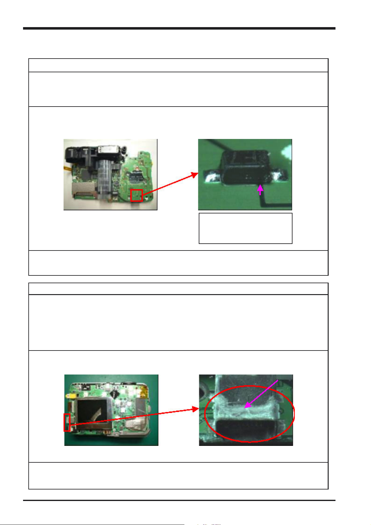
1-1 Power 1
Phenomenon of problem
Power does not come ON.
The current of 3.14A always flows, even if the camera is switched off.
Results of Analysis
Solder on the cathode of the diode (D307) on the main board has flowed under the diode, shorting the
pattern.
Solder has flowed under the di-
ode at the position indicated by
the arrow.
Repair Method
Resolder the diode (D307).
1-2 Power 2
Phenomenon of problem
Power cuts out immediately when either the AC adapter or the battery is used.
When the backup condenser charges the camera detects a USB connection, even though the USB cable is
not connected.
Operation returns to normal when the charge in the backup condenser decreases slightly.
Results of Analysis
Due to corrosion of the USB jack.
Repair Method
Replace main board.
4
<Main unit> <Enlarged view of corrosion>
Page 5

FinePix A310 TROUBLESHOOTING GUIDE
1-3 Power 3
Phenomenon of problem
Power does not come on with either the AC adapter or the battery.
Results of Analysis
Problem with main board.
No output from the transistor (Q302) POWER_ON circuit.
Voltage measurement showed that there was no 3V_ON signal at Q302.
Probably due to a problem with the KEY_IC peripheral circuit.
Repair Method
Replace main board.
1-4 Power 4
Phenomenon of problem
Power does not come ON with the AC adapter.
Results of Analysis
Fuse (F302) on main board blown.
Probably due to the use of a non-standard AC adapter.
It is thought that an excessive current [5A] appropriately 200% of the rated value was applied.
Repair Method
Replace the fuse (F302).
1-5 Power 5
Phenomenon of problem
Power does not come on with either the AC adapter or the battery.
Current of 0.15A at DC_IN, and excessive current at POWER_ON so that power is switched OFF.
Results of Analysis
Analysis by the design section revealed a problem (short) with the tantalum condenser (C322) on the main
board.
Repair Method
Replace tantalum condenser (C322).
5
Page 6
FinePix A310 TROUBLESHOOTING GUIDE
1-6 Power 6
Phenomenon of problem
In both the still and movie modes, power cuts out when the image is about to appear on the LCD.
Results of Analysis
Fuse (F303:-8v/16V line) blown, and problem with power supply IC (IC301)
Possible reasons for damage to the power supply IC (IC301) are as follows.
(1) An external short, or a crack in the solder between the transformer and rectification diodes, in the CCD
voltage output line.
(2) A component in the CCD voltage output line (diode, electrothermal detector resistor) is missing or has
been mounted incorrectly.
(3) Power supply input voltage is between 10V and 12V.
Of the above, (2) is not relevant, and (1) is such that if the problem occurred on the bottom of the component
mounting surface it would be impossible to verify. While improbable, the greatest possibility is (3).
Repair Method
Replace the fuse (F303) on the main board, and the IC (IC301).
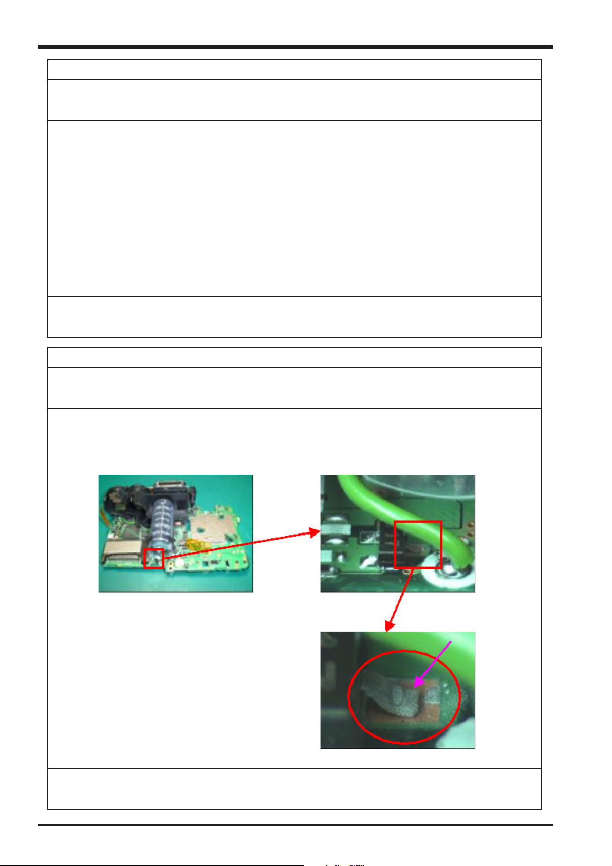
1-7 Power 7
Phenomenon of problem
Power does not come ON.
Results of Analysis
Transistor (Q302) on main board not soldered.
This transistor is responsible for 3V_ON switching. As it is unsoldered the 3.3V is not output, and power
therefore does not come ON.
<Main board> <Transistor (Q302)>
Repair Method
Solder transistor (Q302).
6
<Enlarged view of unsoldered Q302>
Page 7

FinePix A310 TROUBLESHOOTING GUIDE
1-8 Power 8
Phenomenon of problem
Power does not come ON.
Results of Analysis
Due to a short between pins (14) and (15) of the DC_IC (IC301) on the main board caused by a solder ball.
<Area of DC_IC> <Enlarged view of short due to solder ball>
Repair Method
Remove solder ball.
2. Image-related
2-1 Image 1
Phenomenon of problem
Problem with through image.
The image is sometimes completely white, includes horizontal lines, or has a slight purple tinge, and is disrupted.
Results of Analysis
A normal image was displayed when a defect-free lens assembly was fitted.
The same problem occurred when the original lens assembly was assembled into the camera again.
It is therefore concluded that there is a problem with the lens assembly.
Examination of the CCD section of the lens assembly revealed a crack.
It is therefore concluded that this problem is due to a break in the signal line caused by a crack in the CCD section.
<CCD FPC assembly> <Enlarged view from A>
<Enlarged view from B> <Enlarged view from C>
Repair Method
Replace the CCD FPC assembly.
7
Page 8

FinePix A310 TROUBLESHOOTING GUIDE
2-2 Image 2
Phenomenon of problem
Both the LCD and through image display a magenta coloring which returns to normal when the camera is
squeezed in the vertical direction.
Results of Analysis
As the symptoms change when the camera is squeezed, there is the possibility of a problem with contact
or unsatisfactory soldering inside the camera. Dismantling the camera revealed a bent pin on the main
board connector (CN100) receiving the FPC from the lens CCD FPC.
<Main board>
<Enlarged view of bent pin>
Repair Method
Replace the main board connector (CN100).
<Enlarged view of connector (CN100)>
8
Page 9

FinePix A310 TROUBLESHOOTING GUIDE
2-3 Image 3
Phenomenon of problem
No through image (completely black).
Results of Analysis
A shock has resulted in a break in the main board condenser (C100) pattern.
<Front view of case> <Enlarged view of cracking and dent>
<Main board> <Enlarged view of broken PCB pattern>
Repair Method
Replace the main board.
2-4 Image 4
Phenomenon of problem
Problem with exposure. Whitish image when photographing outdoors.
Results of Analysis
Lens problem related to the fact that the lens shutter does not work at S2_ON.
Results of Manufacturer’s Analysis
Dismantling and checking revealed a problem with operation due to deformation of the shutter blade.
Repair Method
Replace the lens assembly.
9
Page 10

FinePix A310 TROUBLESHOOTING GUIDE
2-5 Image 5
Phenomenon of problem
No through image (completely black).
Results of Analysis
Lens problem related to the fact that the lens shutter remains closed.
Results of Manufacturer’s Analysis
Thought to be due to the fact that excessive load was applied to the shutter base board as a result of dent
on the aperture.
Repair Method
Replace the lens assembly.
3. LCD-related
3-1 LCD 1
Phenomenon of problem
LCD not lit (completely black). Problem may be reproduced by pressing from the back.
Results of Analysis
Locking plate problem with main board connector CN550.
Pins raised overall.
<Main board>
<Enlarged view of CN550 of defective camera from A>
Repair Method
Replace main board connector CN550.
10
<Enlarged view of CN550 of normal camera from A>
Page 11

FinePix A310 TROUBLESHOOTING GUIDE
3-2 LCD 2
Phenomenon of problem
A white line is displayed one-third of the way down
the LCD screen.
Results of Analysis
Problem with LCD panel.
Repair Method
Replace LCD unit.
3-3 LCD 3
Phenomenon of problem
Vertical lines on LCD.
Results of Analysis
Problem with LCD panel.
Repair Method
Replace LCD unit.
11
Page 12

FinePix A310 TROUBLESHOOTING GUIDE
3-4 LCD 4
Phenomenon of problem
No image on LCD (completely black).
Results of Analysis
Problem with LCD panel.
FPC connected to back of the LCD FPC component mounting surface is broken.
<Back of LCD FPC> <Enlarged view of broken wiring>
Repair Method
Replace LCD unit.
4. Switch-related
4-1 Switch 1
Phenomenon of problem
S1_ON turns on, but S2_ON does not.
Click can be felt.
Results of Analysis
The FFC between the sub and main boards is broken at the sub board.
Considered to be due to the FFC having been inserted incorrectly.
<FFC between sub and main boards> <Enlarged view of break>
Repair Method
Replace FFC (M304).
12
Page 13

FinePix A310 TROUBLESHOOTING GUIDE
4-2 Switch 2
Phenomenon of problem
Shutter does not operate. No click apparent.
Results of Analysis
The boss fixing the sub board in the ST body of the main board assembly is bent, resulting in displacement
of the sub board so that the release switch is not pressed.
<View from above with back panel removed> <View of sub board of defective camera>
<Bent ST body boss> <View of sub board on normal camera>
Repair Method
Replace the ST body.
4-3 Switch 3
Phenomenon of problem
The flash select button does not work.
Results of Analysis
The flash select button has been subjected to a shock, resulting in it being stuck in the ON position.
The switch (SW501) has collapsed.
<Flash select switch (SW501) in defective camera> <Other switch (SW502) in defective camera>
Repair Method
Replace SW501.
13
Page 14

FinePix A310 TROUBLESHOOTING GUIDE
5. Video Out-related
5-1 Video 1
Phenomenon of problem
No video signal.
Results of Analysis
The video out jack (J453) on the main board is bent inwards, and the terminals are therefore open when the
video cable is not inserted, however when the video cable is inserted the terminals are shorted and the signal
is not output.
<Video jack on defective camera> <Video jack on normal camera>
Repair Method
Replace the video jack (J453).
6. Zoom Lens-related
6-1 Zoom 1
Phenomenon of problem
A lens error is displayed, and the lens does not move.
Not reproduced with SS.
Results of Analysis
Scratches on the tube in the moving part of the lens suggest that the lens has been subjected to some form
of shock.
Results of Manufacturer’s Analysis
Bending of the rib on the movable lens on the objective side of the finder unit has resulted in an increase in
load when zoom is used. Considered to be due to application of a shock.
Repair Method
Replace lens.
14
Page 15

FinePix A310 TROUBLESHOOTING GUIDE
6-2 Zoom 2
Phenomenon of problem
Focus error (The inner lens catches at the close-up end, interfering with operation, and resulting in an
abnormal sound).
Results of Analysis
Bending of pin (9) on the connector (CN650) on the main board has resulted in an abnormality in LED3.3V
for ZOOMHP_PI, and caused abnormal focus operation.
<Main board> <Enlarged view of connector (CN650)>
<Enlarged view of damaged section>
Repair Method
Replace the main board connector (CN650) and the lens assembly.
15
Page 16

FinePix A310 TROUBLESHOOTING GUIDE
6-3 Zoom 3
Phenomenon of problem
Lens does not retract, and a zoom error is displayed.
Use of the zoom switch does not result in any movement.
Results of Analysis
Dismantling the camera and checking the FPC on the drive side of the lens revealed that one side of the
locking plate of the connector (CN650) from the lens FPC to the main board was raised.
<Main board>
<Enlarged view of normal lateral locking plate> <Enlarged view of broken lateral locking plate>
Repair Method
Lock the main board connector (CN650) again.
<Enlarged view of connector (CN650)>
16
Page 17

FinePix A310 TROUBLESHOOTING GUIDE
6-4 Zoom 4
Phenomenon of problem
Focus error (The inner lens catches at the close-up end, interfering with operation, and resulting in an
abnormal sound).
Results of Analysis
Pin (14) on the main board connector (CN650) has become disconnected, affecting the pin (15) line.
Due to the fact that the ZPOSI_E (zoom position emitter) signal cannot be sent and the zoom position is
therefore not determined, and the camera continuously attempts to focus.
<Main board> <Enlarged view of connector (CN650)>
<Enlarged view of damaged section>
Repair Method
Replace the main board connector (CN650).
17
Page 18

FinePix A310 TROUBLESHOOTING GUIDE
6-5 Zoom 5
Phenomenon of problem
Apparently random focusing error.
Results of Analysis
Pins (1) and (2) on the main board connector (CN650) are bent, resulting in an abnormal FPI_E signal (focus
PI), and consequent abnormal focus operation.
<Main board> <Enlarged view of connector (CN650)>
<Enlarged view of bent pins>
Repair Method
Replace the main board connector (CN650).
18
Page 19

FinePix A310 TROUBLESHOOTING GUIDE
<MEMO>
19
Page 20

FUJI PHOTO FILM CO., LTD.
26-30, Nishiazabu 2-chome, Minato-ku, Tokyo 106-8620, Japan.
 Loading...