

FUJIFILM FinePix A210 TROUBLE SHOOTING GUIDE
DIGITAL CAMERA
FinePix A210
TROUBLE SHOOTING GUIDE
WARNING
THE COMPORNENTS IDENTIFIED BY THE MARK “ ” ON THE SCHEMATHIC
DIAGRAM AND IN THE PARTS LIST ARE CRITICAL FOR SAFETY.
PLEASE REPLACE ONLY BY THE COMPONENTS SPECIFIED ON THE SCHEMATHIC
DIAGRAM AND IN THE PARTS LIST.
IF YOU USE WITH PART NUMBER UN-SPECIFIED, IT MAY RESULT IN A FIRE AND AN
ELECTORICAL SHOCK.
Ref.No.:ZM00504-400
FUJI PHOTO FILM CO.,LTD.
Printed in Japan 2004.1(H.I.)
SAFETY CHECK-OUT
2. Check the interboard wiring to ensure that no wires
are “pinched” or contact high-wattage resistors.
FinePixA210 Trouble shooting guide
2.5A 125V
2.5A 125V
RISK OF FIREREPLACE FUSE
AS MARKED
WARNING!
HIGH VOLTAGE
2

FinePix A210 Trouble shooting guide
7.Appndix
TABEL OF TROUBLE SHOOTING
1-1. The camera does not turn on. ......................................................................................................................... 4
1-2. The camera does not turn on. ......................................................................................................................... 5
1-3. The camera does not turn on when the battery is used. .................................................................................. 5
2. The camera does not work (AC or battery) ......................................................................................................... 5
3-1. Only a few pictures can be taken when the battery is used. .......... .................................................................. 5
3-2. Only a few pictures can be taken when the battery is used. .......... .................................................................. 6
4. Lens fails to extend, retract or operate. .............................................................................................................. 6
5. Peeling of the lens coating.................................................................................................................................. 6
6. Focusing error .................................................................................................................................................... 6
8. USB recognition fails. ......................................................................................................................................... 7
9. The "LENS COVER!" message appears even though the lens cover is open..................................................... 7
7-1. Lens fails to extend ("Zoom Error" displayed).................................................................................................. 7
7-2. Lens fails to extend ("Zoom Error" displayed).................................................................................................. 7
10-1. The T side of the zoom switch does not work................................................................................................ 8
10-2. The T side of the zoom switch does not work................................................................................................ 8
1 1. After the shutter is released, the image appears on the LCD monitor and then freezes.................................... 8
12-1. No image appears on the LCD monitor.......................................................................................................... 8
12-4. No image appears on the LCD monitor.......................................................................................................... 9
12-5. No image appears on the LCD monitor.......................................................................................................... 9
12-2. No image appears on the LCD monitor.......................................................................................................... 9
12-3. No image appears on the LCD monitor.......................................................................................................... 9
16. Photographed image cannot be played back. ................................................................................................. 10
12-6. No image appears on the LCD monitor...................................................................................... .................. 10
13. Horizontal lines on the LCD monitor ................................................................................................................ 10
14. LCD monitor image defect (colors too pale).................................................................................................... 10
15. Video output failure......................................................................................................................................... 10
17. Photographed image problems (live images also) ...........................................................................................11
18. The viewfinder indicator does not light.............................................................................................................11
19. The date/time setting is not backed up. ...........................................................................................................11
3
FinePixA210 Trouble shooting guide
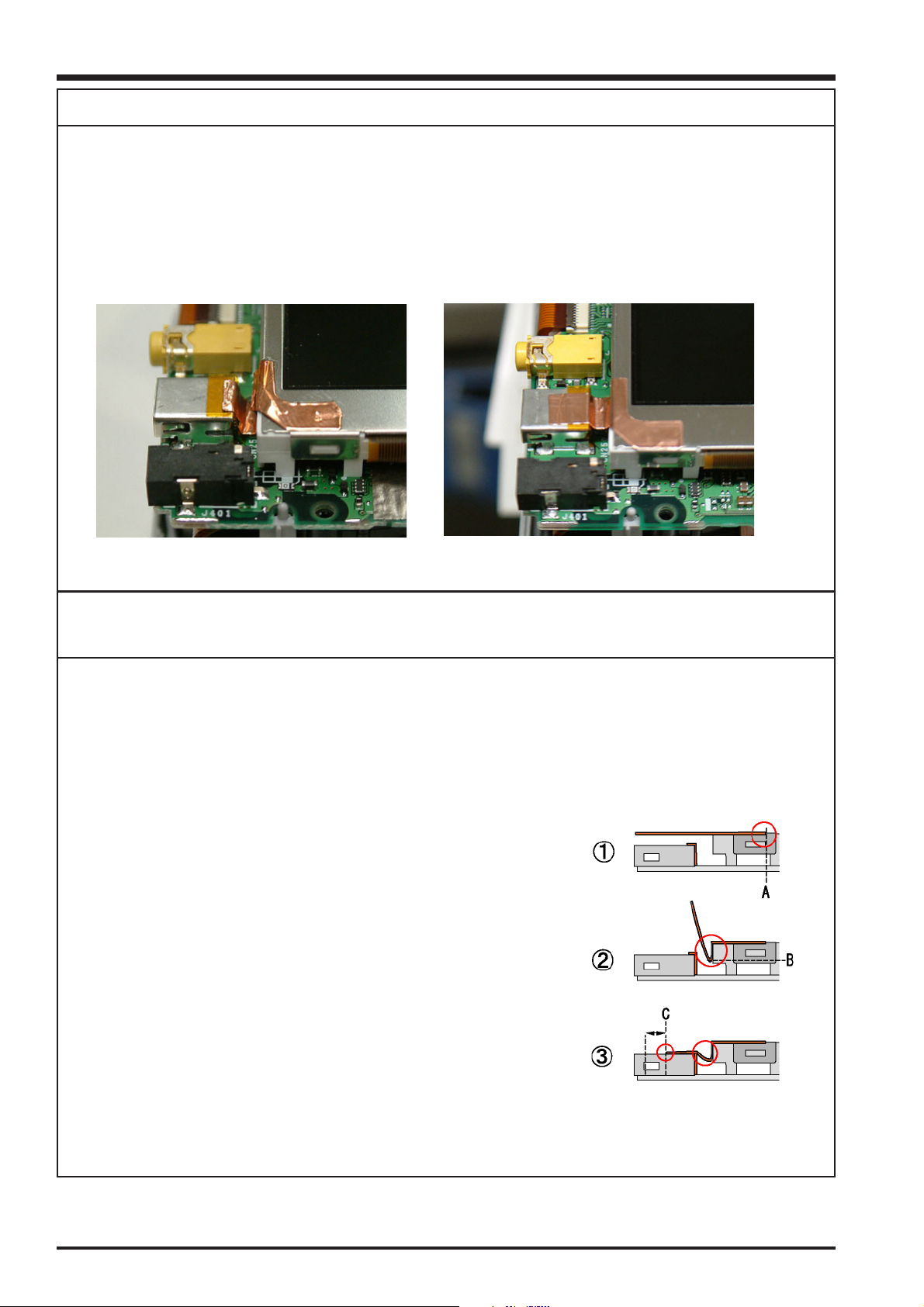
1-1 The camera does not turn on.
<Fault details>
A short-circuit occurs when the power supply is connected.
<Analysis results>
The CU SHEET (M282) was not affixed as set out in the specifications.
A slack section of the sheet hangs down onto the MAIN PWB ASSY and makes contact with FB401 (UNREG).
<Faulty sample> <Correctly affixed sample>
<Repair details>
Af fix the CU SHEET (M282) in the location stipulated in the specifications.
<Note>
The purpose of the CU SHEET is to ensure that electrical potential is the same between the LCD monitor (M240) and
CN250, and it must be attached to the metal sections (GND) on both the LCD monitor and CN250.
(* The adhesive surface of the CU SHEET is made of a conductive material.)
If the CU SHEET is not affixed in the location stipulated in the specifications, or if the CU SHEET is affixed in the course of
other repairs, refer to "Location of Sheet Parts" on page 15 of the Service Manual and to the affixing procedure below.
(1) Position the edge of the CU SHEET so that it is aligned with the section where
the LCD monitor metal frame fits against the bottom (A) and then stick the
sheet in place.
(2) Stick the CU SHEET down as far as the lower edge (B) of the LCD side face.
(3) Position the other edge of the CU SHEET close to the middle of the CN250
upper side (C) and affix it in place. Stow any slack in the gap between CN250
and the LCD monitor.
* It is also OK for (C) to be closer to the CN250 insertion slot than to the middle.
(4) Check that the slack portion of the CU SHEET does not touch the MAIN PWB
ASSY.
*This item also applies to the FinePix A205/A205S.
4
 Loading...