

FUJIFILM FinePix A210 SERVICE MANUAL
DIGITAL CAMERA
FinePix A210
SERVICE MANUAL
WARNING
THE COMPORNENTS IDENTIFIED BY THE MARK “ ” ON THE SCHEMATHIC
DIAGRAM AND IN THE PARTS LIST ARE CRITICAL FOR SAFETY.
PLEASE REPLACE ONLY BY THE COMPONENTS SPECIFIED ON THE SCHEMATHIC
DIAGRAM AND IN THE PARTS LIST.
IF YOU USE WITH PART NUMBER UN-SPECIFIED, IT MAY RESULT IN A FIRE AND AN
ELECTORICAL SHOCK.
Ref.No.:ZM00504-102
FUJI PHOTO FILM CO.,LTD.
Printed in Japan 2003.10(H.I.)
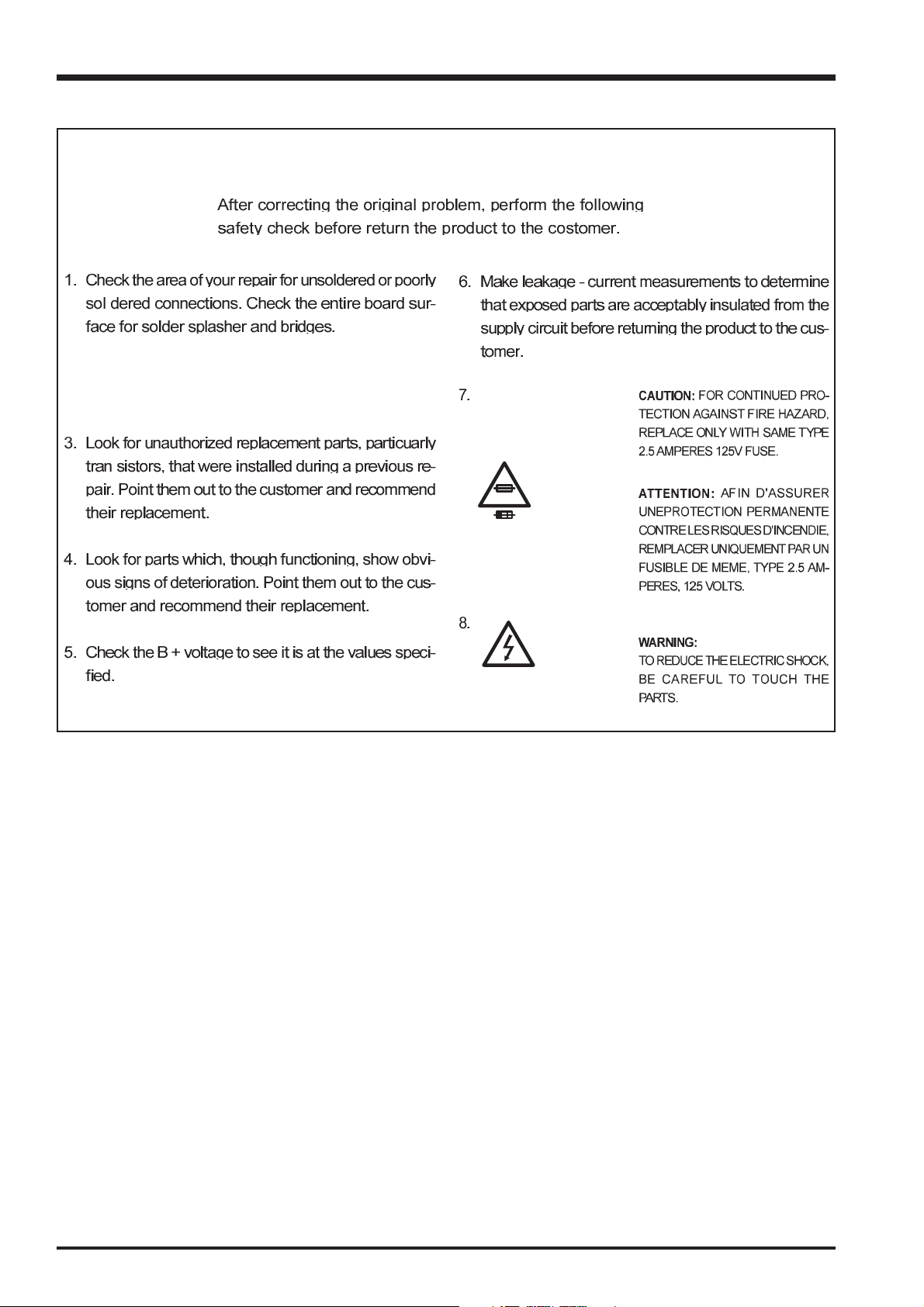
SAFETY CHECK-OUT
2. Check the interboard wiring to ensure that no wires
are “pinched” or contact high-wattage resistors.
FinePix A210 Service Manual
2.5A 125V
2.5A 125V
RISK OF FIREREPLACE FUSE
AS MARKED
WARNING!
HIGH VOLTAGE
2

INDEX
1.General.........................................5
1-1. Product specification.............................................5
1-2.Explanation of Terms..............................................7
1-3.Names of External Components ............................ 7
2. Disassembly ...............................9
2-1.Names of Internal Parts ......................................... 9
2-2.How to Disassemble the CABI R ASSY. ................9
2-3.How to Disassemble the LCD CONST ................ 11
2-4.How to Disassemble the Internal UNIT................ 11
2-5.How to Disassemble the BATTERY LID .............. 11
2-6.How to Disassemble the CABI INNER................. 11
2-7.How to Disassemble the LENS BARRIER...........13
2-8.How to Disassemble the BARRIER PLATE......... 13
2-9.How to Disassemble the LENS UNIT ..................13
2-10.How to Disassemble the CCD ...........................13
2-11.How to Disassemble the ST BODY .................... 15
2-12.How to Disassemble the SUB PWB ..................15
2-13.How to Disassemble the STRB_MODULE ........ 15
2-14.Location of Sheet Parts...................................... 15
3.Circuit Diagrams ....................... 16
3-1.Cautions............................................................... 16
3.2 Names and Functions of Basic Blocks................. 17
3-3.Explanation of Functions of Important Blocks...... 17
3-3-1.Technical Overview ..................................... 17
3-3-2.Explanation of Functions of Individual Blocks.....17
3-4.Block Diagram...................................................... 19
3-5.Overall..................................................................19
3-6.Mounted Parts Diagrams ..................................... 21
3-6-1.MAIN PWB ASSY Component Locations ...21
3-6-2.SUB PWB ASSY Component Locations.....21
3-7.Circuit Diagrams ..................................................21
3-7-1.DCDC BLOCK Circuit .................................21
3-7-2.CAM BLOCK Circuit .................................... 23
3-7-3.PROCESS BLOCK Circuit .......................... 23
3-7-4.STB BLOCK Circuit ..................................... 25
3-7-5.MOTOR BLOCK Circuit............................... 25
3-7-6.KEY IC BLOCK Circuit ................................ 27
3-7-7.KSW BLOCK Circuit ...................................27
3-7-8.VIDEO BLOCK Circuit................................. 29
3-7-9.LCD COF BLOCK Circuit ............................29
3-7-10.RSW BLOCK Circuit ................................. 29
4. Adjustments.............................. 31
4-1. Adjustment Procedure of Parts Replacement.....31
4-2.Measuring Instrument List.................................... 31
4-3.Jigs.......................................................................31
4-4.Jig Connections ...................................................31
4-5.Environmental Setup............................................ 31
4-6.Installing the Jig Drivers on the PC...................... 33
4-7.Installing and Starting the Adjustment Software ..33
4.8 Initial Settings of the Adjustment Software...........35
4-9. Starting the Adjustment Software........................37
4.10 [F6]: AF Adjustments ..........................................39
4-11. [F5]: Camera Adjustments................................. 41
4-12. [F4]: CCD Defect Correction .............................43
4-13. [F7]: Flash adjustment ......................................45
4-14. [F11]: Video Adjustments ..................................45
4-15. [F1]: Battery Voltage Adjustments ..................... 47
4-16. [F12] : End Setting ............................................ 49
5.Inspection ..................................51
5-1.Required Measuring Equipment .......................... 51
5-2.Connection of Measuring Equipment................... 51
5-3.Inspection and Factory Settings ..........................51
6.Parts list ..................................... 53
6-1.Packing and Accessoris....................................... 53
6-1-1.US model ....................................................53
6-1-2.CA model..................................................... 53
6-1-3.EU model ....................................................55
6-1-4.EG model .................................................... 55
6-1-5.GE model .................................................... 57
6-1-6.AS model..................................................... 57
6-1-7.CH MODEL .................................................58
6-1-8. JP model.................................................... 59
6-2.Cabinet F block / Inner parts................................60
6-3.Cabinet R block.................................................... 61
6-3-1.Cabinet R block US/CA/EU/EG/GE/AS/JP MODEL 61
6-3-2.Cabinet R block CH MODEL......................62
6-4.Electrical parts......................................................63
7.Appendix ....................................65
7-1. Version display function ...................................... 65
7-2.List of Related Technical Updates Issued............65
3

FinePix A210 Service Manual
1.General
1-1. Product specification
System
Model Digital camera FinePix A210
Number of effective pixels 3.2 million pixels
CCD sensor 1/2.7-inch square pixel CCD
Number of total pixels 3.34 million pixels
Number of recorded pixels
Storage media xD-Picture Card (16/32/64/128/256 MB)
File format Still image: JPEG (Exif ver. 2.2)
Lens Fujinon 3× optical zoom lens
Aperture F3 to F4.8/F7 to F10.8 (automatically selected)
Focus length f=5.5 mm to 16.5 mm (Equivalent to 36 mm to 108 mm on a 35 mm camera)
Focal range Normal: Approx. 0.8 m (2.6 ft.) to infinity
Shutter speed 1/2 sec. to 1/2000 sec. (combined with mechanical shutter)
Focus TTL contrast-type, Auto focus
Sensitivity Equivalent to ISO100
Photometry TTL 64-zones metering
Exposure control Program AE
Exposure compensation
White balance Auto
Viewfinder Real image optical Approx. 80% coverage
LCD monitor 1.5-inches, 60,000-pixel Amorphous silicon TFT, Approx. 92% coverage
Flash Auto flash using flash control sensor
Self-Timer 10 sec.
Video output NTSC/PAL selectable
Standard number of available frames/recording time per xD-Picture Card
The number of available frames, recording time or file size varies slightly depending on the subjects photographed. Note also
that the divergence between standard number of available frames and the actual number of available frames is greater for
xD-Picture Cards with higher capacities.
Quality mode
Number of recorded pixels
Image Data Size
DPC-16 (16 MB)
DPC-32 (32 MB)
DPC-64 (64 MB)
DPC-128 (128 MB)
DPC-256 (256 MB)
Still image: 2048 × 1536 pixels/1600 × 1200 pixels/1280 × 960 pixels/
640 × 480 pixels ( / / / )
Movie: 320 × 240 pixels (10 frames per second without sound)
160 × 120 pixels (10 frames per second without sound)
* Design rule for Camera File System compliant DPOF compatible
Movie: AVI format, Motion JPEG
Macro: Approx. 0.1 m (3.9 in.) to 1.0 m (3.3 ft.)
-2.1 EV to +1.5 EV in 0.3-step increments (in Manual mode)
Manual modes, 7 positions can be selected
Effective range: Wide-angle: Approx. 0.8 m to 3.5 m (2.6 ft. to 11.5 ft.)
(Approx. 0.3 m to 1.0 m (1.0 ft. to 3.3 ft.): Macro)
Telephoto: Approx. 0.8 m to 3.0 m (2.6 ft. to 9.8 ft.)
Flash modes: Auto, Red-Eye Reduction, Forced Flash, Suppressed Flash, Slow
Synchro*, Red-Eye Reduction + Slow Synchro*
* In Manual mode
2048
780 KB
3M
1536
19
40
81
162
325
1600
630 KB
25
50
101
204
409
2M
1200
1280
470 KB
33
68
137
275
550
1M
960
640
130 KB
122
247
497
997
1997
0.3M
480
Movie
320 240
–
Approx. 98 sec.
Approx. 199 sec.
Approx. 6.6 min.
Approx. 13.3 min.
Approx. 26.7 min.
Movie
160 120
–
Approx. 5.6 min.
Approx. 11.3 min.
Approx. 22.7 min.
Approx. 45.5 min.
Approx. 91.2 min.
Input/Output Terminals
Video output socket 2.5 mm dia. jack
(USB) socket For file transfer to a computer and connection to the optional cradle
DC Input Socket for specified AC power adapter AC-3V (sold separately)
Connection for the AC Power Adapter AC-3VW bundled with the cradle (sold separately)
4

Power Supply and Others
Power supply Use one of the following:
• 2×AA-size alkaline batteries
• Rechargeable Battery NH-10 (sold separately)
• 2×AA-size Ni-MH (Nickel-Metal Hydride) batteries (sold separately)
• AC-3VW (PictureCradle CP-FXA10, Sold separately)
• AC Power Adapter AC-3V (sold separately)
Guide to the number
of available frames
for battery operation
Conditions for use Temperature: 0oC to +40oC (+32oF to +104oF); 80% humidity or less (no condensation)
Camera dimensions 98.5 mm × 65 mm × 52.5 mm/3.9 in. × 2.6 in. × 2.1 in.
(W/H/D) (not including accessories and attachments)
Camera mass (weight)
Weight for photography
Accessories 16 MB, xD-Picture Card (1) Included with: Anti-static case (1)
Optional Accessories xD-Picture Card
Battery Type With LCD monitor ON With LCD monitor OFF
Alkaline batteries Approx. 200 frames Approx. 300 frames
Rechargeable Battery
NH-10
Ni-MH batteries 2100 mAh Approx. 330 frames Approx. 440 frames
Approx. 300 frames Approx. 400 frames
The number of available frames for battery operation given here is a guide to the
number of consecutive frames that can be taken under FUJIFILM test conditions.
• Batteries used: Using the alkaline batteries bundled with the camera
Using Ni-MH batteries or the NH-10 Rechargeable Battery at full
charge
• Shooting conditions: Measured at normal temperature with 50% flash use
• Note: The number of available frames varies depending on the capacity of the
alkaline batteries and the amount of charge in the Ni-MH batteries or NH-10
Rechargeable Battery. Consequently, FUJIFILM makes no guarantee with regard to the numbers of available frames for battery operation given here. Note
that the number of available frames will be lower at low temperatures.
Approx. 175 g/6.2 oz.
(not including accessories, batteries and xD-Picture Card)
Approx. 225 g/7.9 oz. (including batteries and xD-Picture Card)
LR6 AA-size alkaline Batteries (2) Strap (1)
Special video cable 2.5 mm dia. plug-to-pin plug Approx. 1.5 m (1)
Cradle adapter for FinePix A205/FinePix A210 (1)
USB Interface Set (1)
• CD-ROM: Software for FinePix SX (1)
• USB cable (included) with Noise Suppression core (1)
• Quick start guide for Camera and Software installation (1)
Owner’s Manual (1)
DPC-16 (16 MB)/DPC-32 (32 MB)/DPC-64 (64 MB)/DPC-128 (128 MB)/
DPC-256 (256 MB)
AC Power Adapter AC-3V Fujifilm Rechargeable Battery 2HR-3UF
Fujifilm Battery charger with Battery BK-NH/BK-NH2 (With Euro type or UK type plug)
PictureCradle CP-FXA10 Rechargeable Battery NH-10 SC-FX26
Image Memory Card Reader DPC-R1
• Compatible with Windows 98/98 SE, Windows Me, Windows 2000 Professional, Windows XP or iMac, Mac OS 8.6 to 9.2.2, Mac OS X (10.1.2 to
10.2.2) and models that support USB as standard.
• Compatible with xD-Picture Card of 16 MB to 256 MB, and SmartMedia of
3.3V, 4 MB to 128 MB.
PC Card Adapter DPC-AD
• Compatible with xD-Picture Card of 16 MB to 256 MB, and SmartMedia of
3.3V, 2 MB to 128 MB.
CompactFlash Card Adapter DPC-CF
• Windows 95/98/98 SE/Me/2000 Professional/XP
• Mac OS 8.6 to 9.2/X (10.1.2 to 10.1.5)
5

FinePix A210 Service Manual
1-2.Explanation of Terms
Deactivated batteries: Leaving an Ni-MH battery unused in storage for a long period may cause a rise in
the level of substances that inhibit current flow inside the battery and result in a
dormant battery. A battery in this state is referred to as deactivated.
Because current flow is inhibited in a deactivated Ni-MH battery, the battery’s
original level of performance cannot be achieved.
DPOF: Digital Print Order Format
DPOF is a format used for recording information on a storage media (image
memory card, etc.) that allows you to specify which of the frames shot using a
digital camera are printed and how many prints are made of each image.
EV: A number that denotes Exposure Value. The EV is determined by the brightness
of the subject and sensitivity (speed) of the film or CCD. The number is larger for
bright subjects and smaller for dark subjects. As the brightness of the subject
changes, a digital camera maintains the amount of light hitting the CCD at a constant level by adjusting the aperture and shutter speed.
When the amount of light striking the CCD doubles, the EV increases by 1. Likewise, when the light is halved, the EV decreases by 1.
Frame rate (fps): The frame rate is a unit used to indicate the number of images (frames) played
back per second. This camera shoots movie files at 10 consecutive frames per
second, a rate that is expressed as 10 fps. By comparison, TV images are played
at 30 fps.
JPEG: Joint Photographics Experts Group
A file format used for compressing and saving color images. The compression
ratio can be selected, but the higher the compression ratio, the poorer the quality
of the expanded image.
Memory effect: If an Ni-MH battery is repeatedly charged without first being fully discharged, its
performance may drop below its original level. This is referred to as the “memory
effect”.
Motion JPEG: A type of AVI (Audio Video Interleave) file format that handles images and sound
as a single file. Images in the file are recorded in JPEG format. Motion JPEG can
be played back by QuickTime 3.0 or later.
PC Card: A generic term for cards that meet the PC Card Standard.
PC Card Standard: A standard for PC cards determined by the PCMCIA.
PCMCIA: Personal Computer Memory Card International Association (US).
White Balance: Whatever the kind of the light, the human eye adapts to it so that a white object
still looks white. On the other hand, devices such as digital cameras see a white
subject as white by first adjusting the color balance to suit the color of the ambient
light around the subject. This adjustment is called matching the white balance. A
function that automatically matches the white balance is called an Automatic
White Balance function.
Exif Print: Exif Print Format is a newly revised digital camera file format that contains a vari-
ety of shooting information for optimal printing.
6
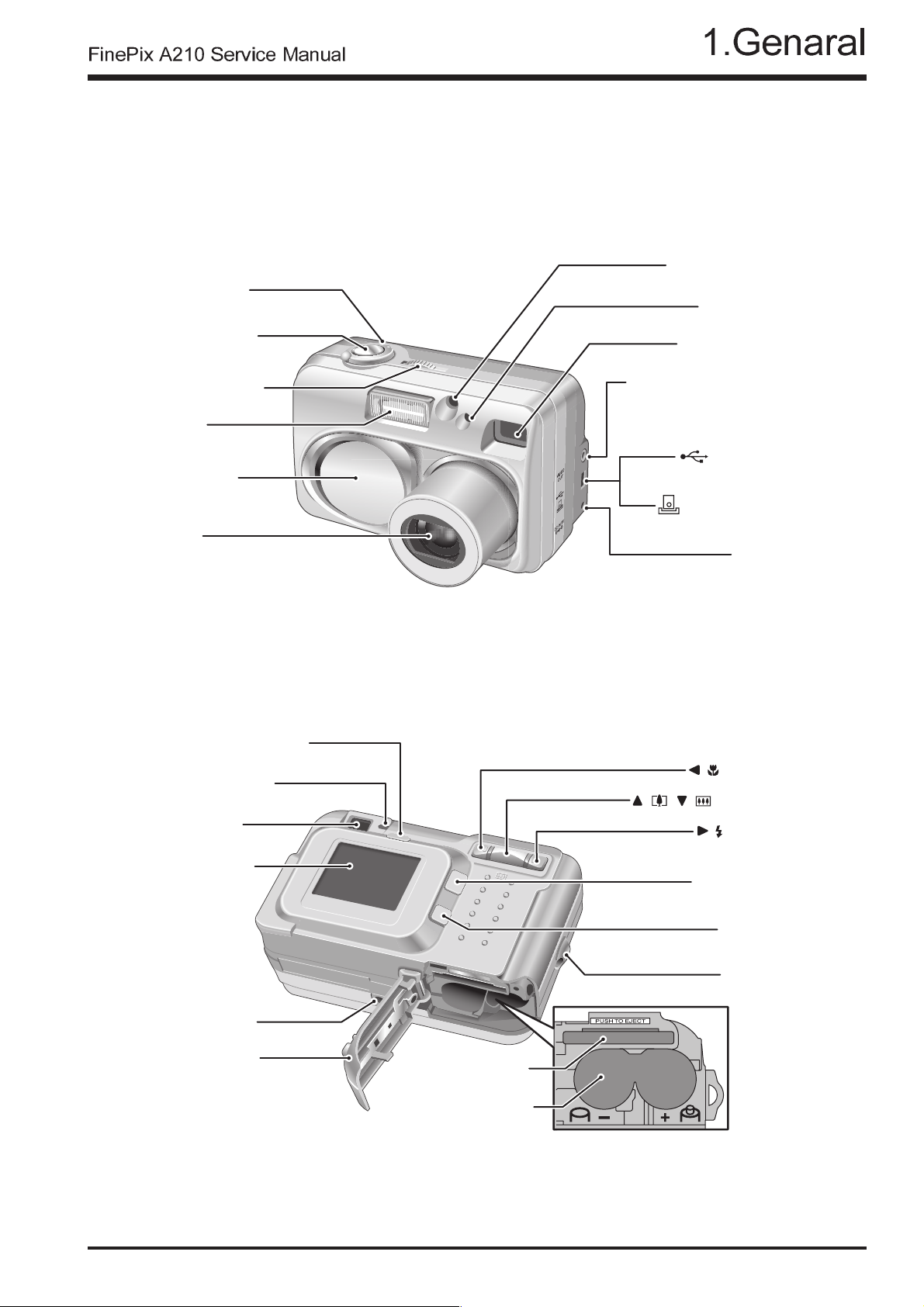
1-3.Names of External Components
Mode switch
Flash control sensor
Self-timer lamp
Shutter button
POWER switch
Flash
Lens cover
Lens
DISP (Display) button
Viewfinder lamp
Viewfinder
Viewfinder Window
VIDEO OUT (Video output)
Cradle connection
(power input) socket
/ Macro button
( ) ( )
socket
(USB) socket
socket
DC IN 3V
/Zoom switch
/ Flash button
LCD monitor
Tripod mount
Battery cover
MENU/OK button
BACK button
Strap mount
xD-Picture Card slot
Battery compartment
7
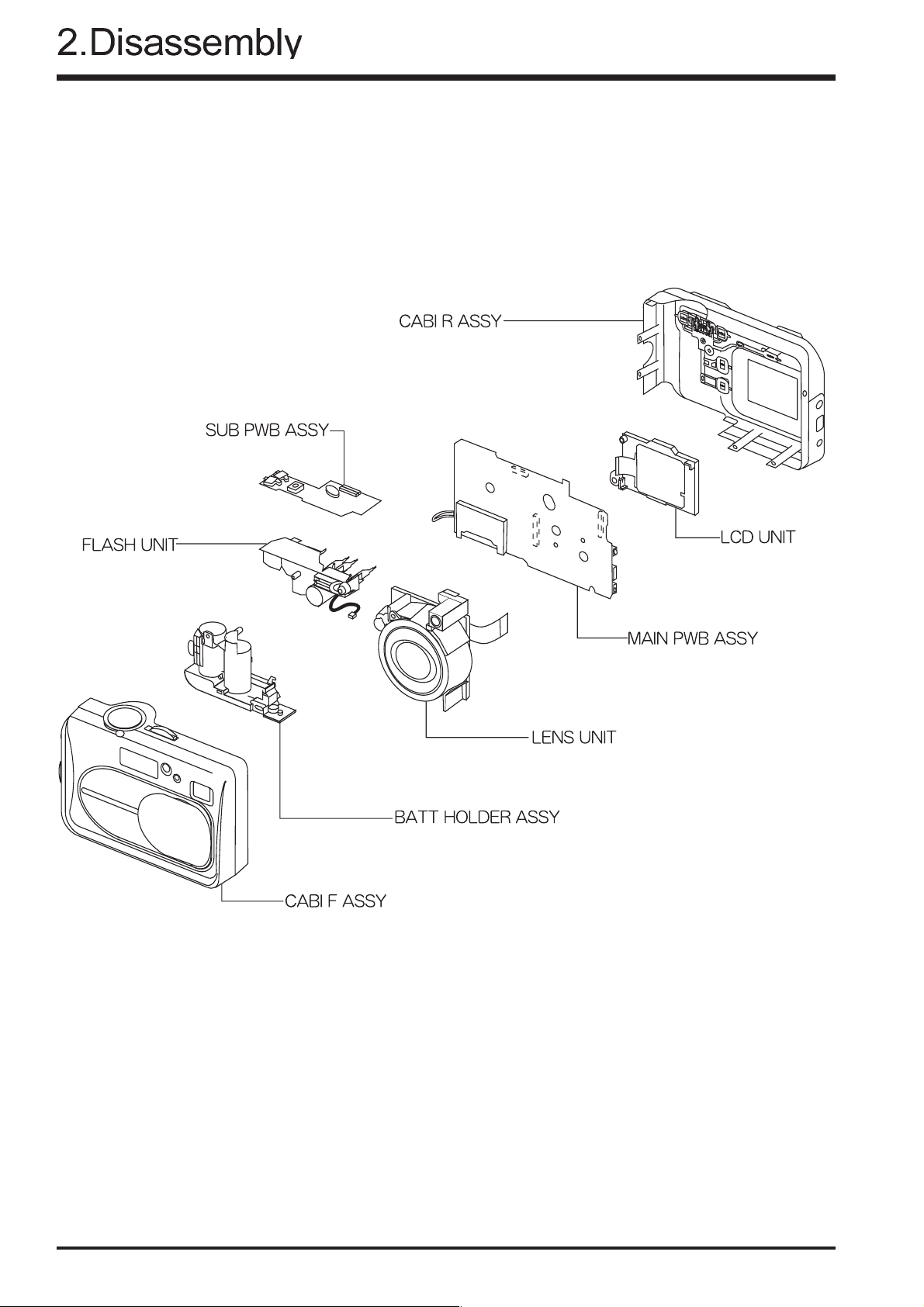
2. Disassembly
2-1.Names of Internal Parts
FinePix A210 Service Manual
8
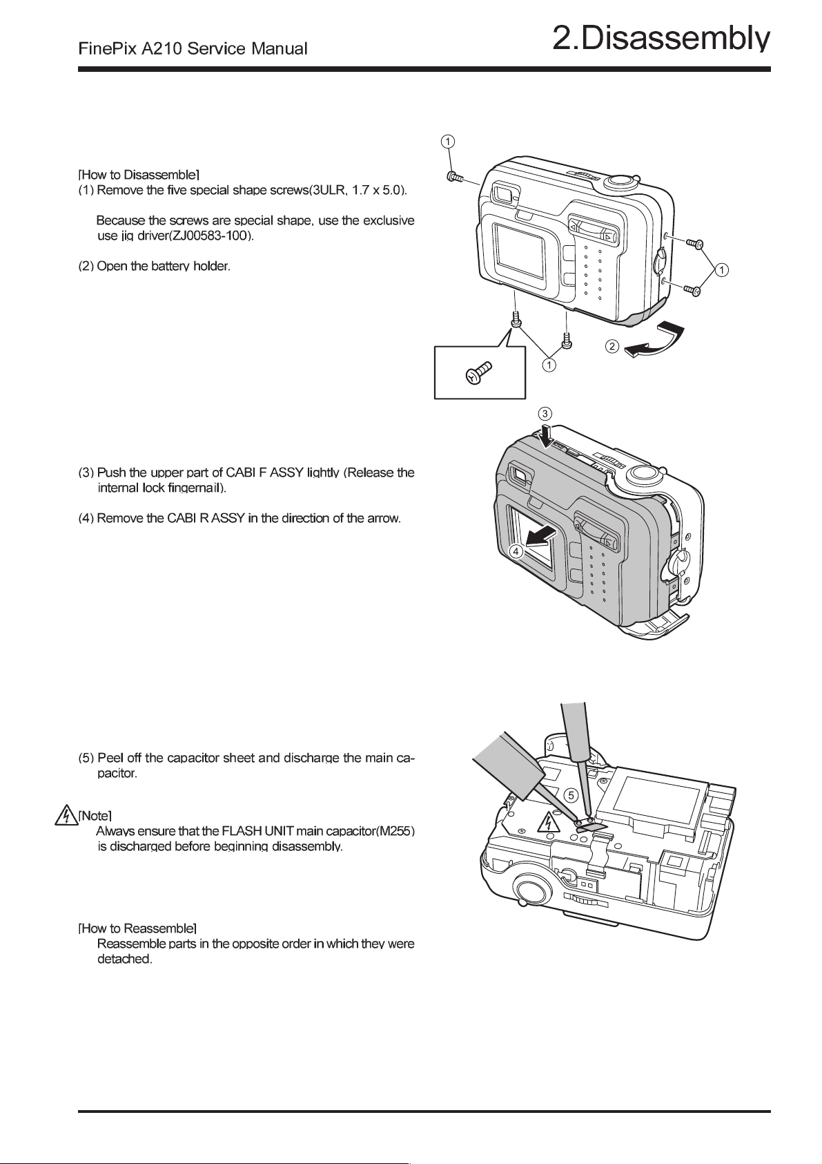
2-2.How to Disassemble the CABI R ASSY.
9
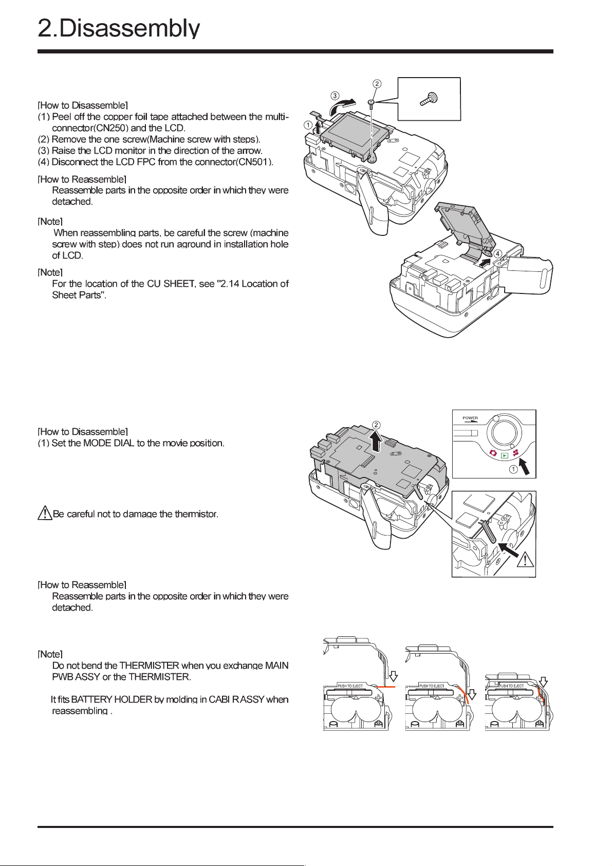
2-3.How to Disassemble the LCD CONST
[Note]
Do not use the removed "
Use surely new parts at the time of reassembly.
CU SHEET and K TAPE 1" .
FinePix A210 Service Manual
2-4.How to Disassemble the Internal UNIT
(2) Being careful of the shutter release button, remove the
Internal UNIT in the direction of the arrow.
10
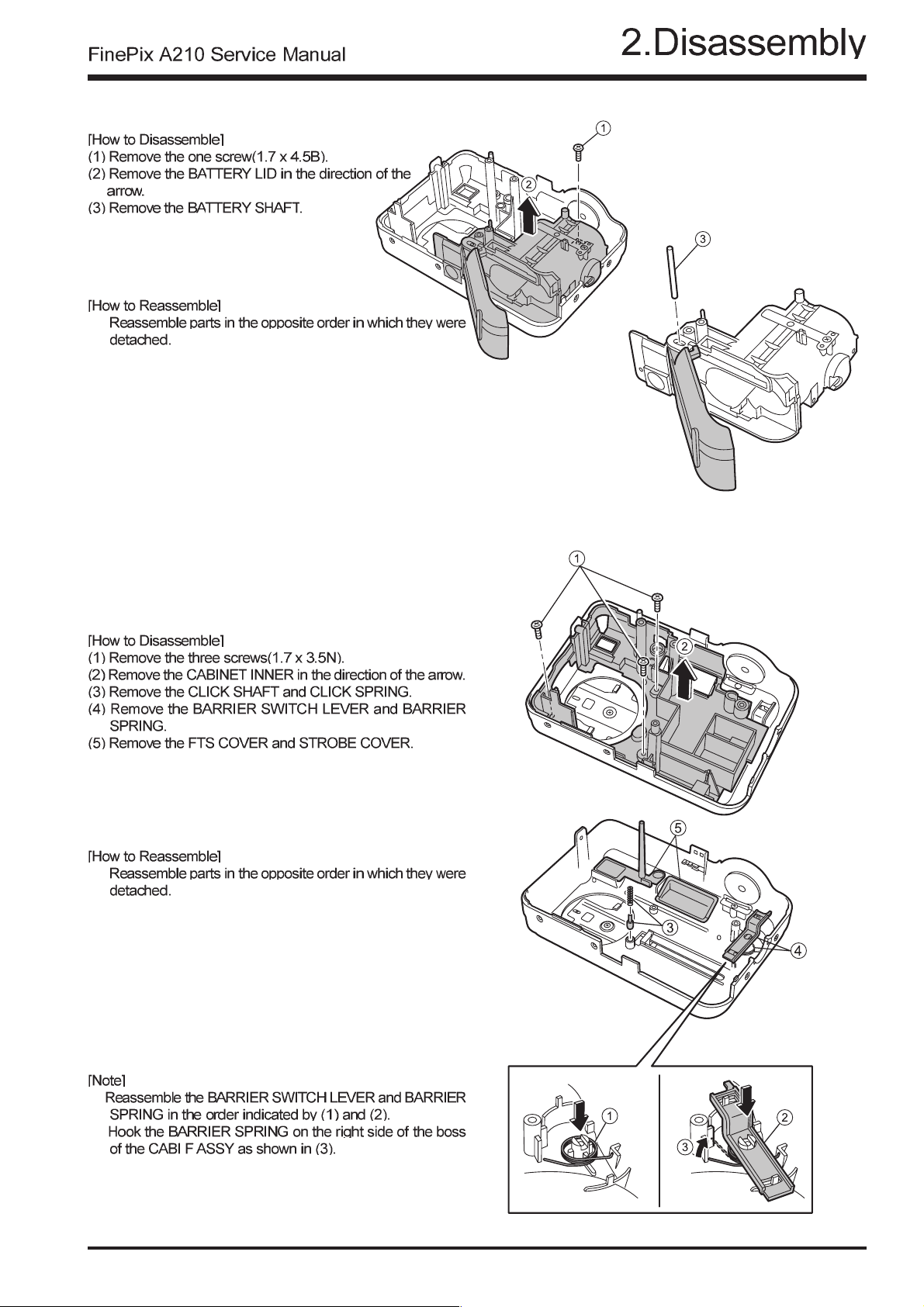
2-5.How to Disassemble the BATTERY LID
2-6.How to Disassemble the CABI INNER
11
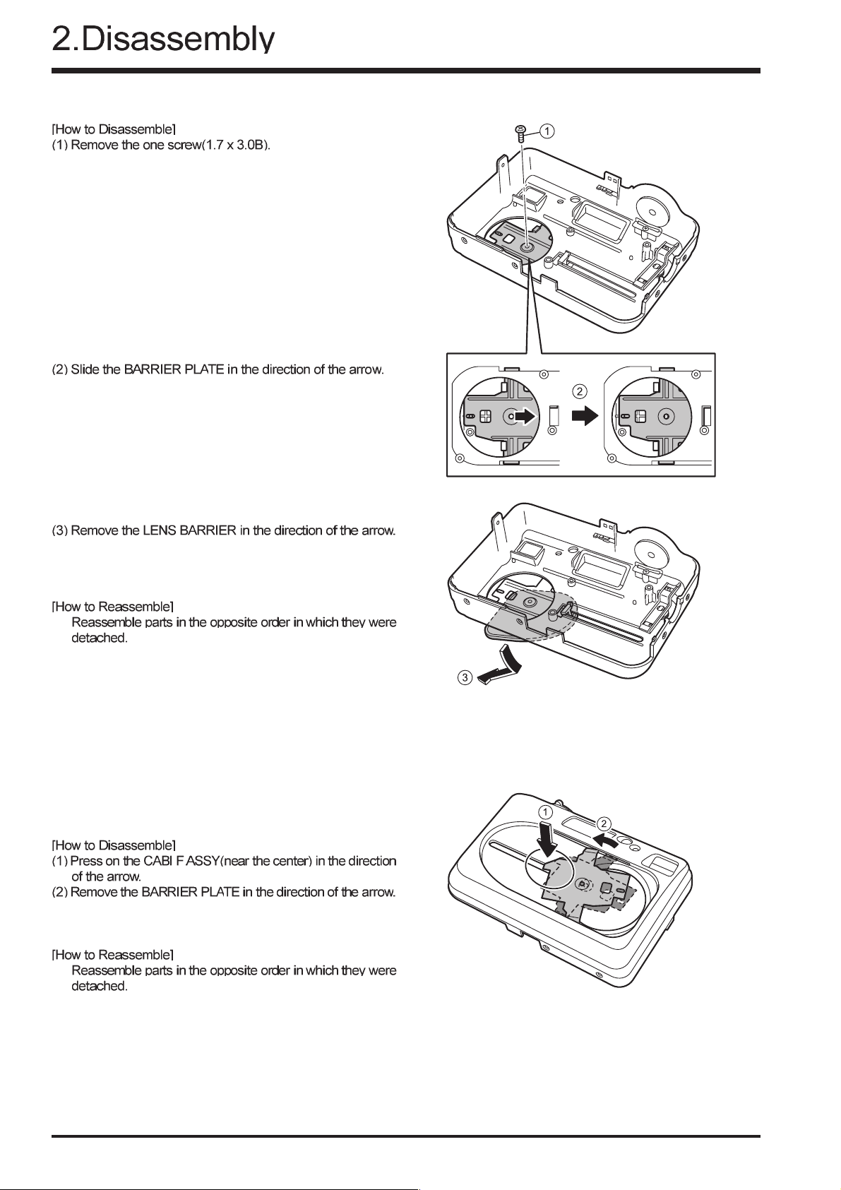
2-7.How to Disassemble the LENS BARRIER
FinePix A210 Service Manual
2-8.How to Disassemble the BARRIER PLATE
12
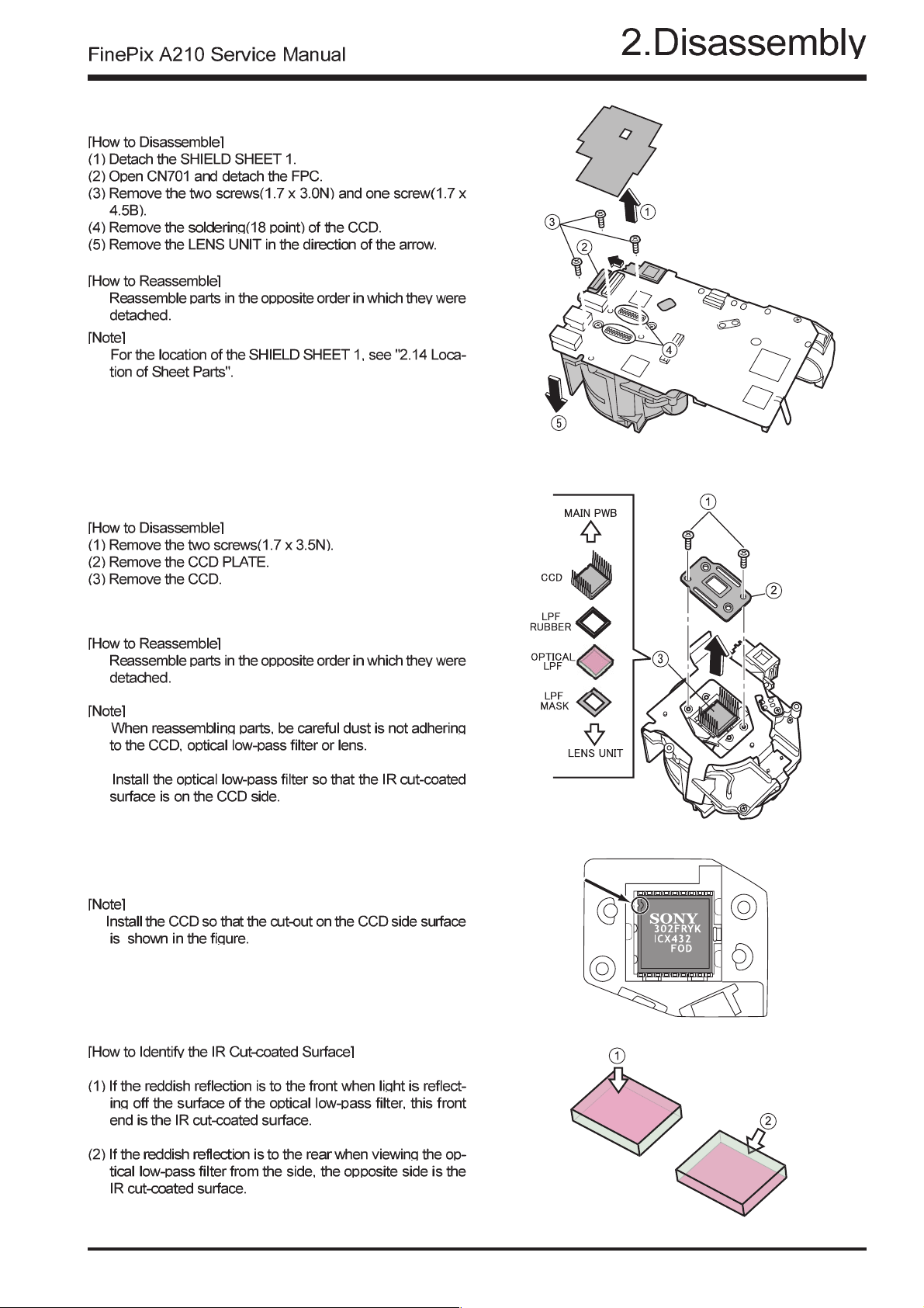
2-9.How to Disassemble the LENS UNIT
[Note]
Do not use the removed "
Use surely new parts at the time of reassembly.
SHIELD SHEET 1" .
2-10.How to Disassemble the CCD
13
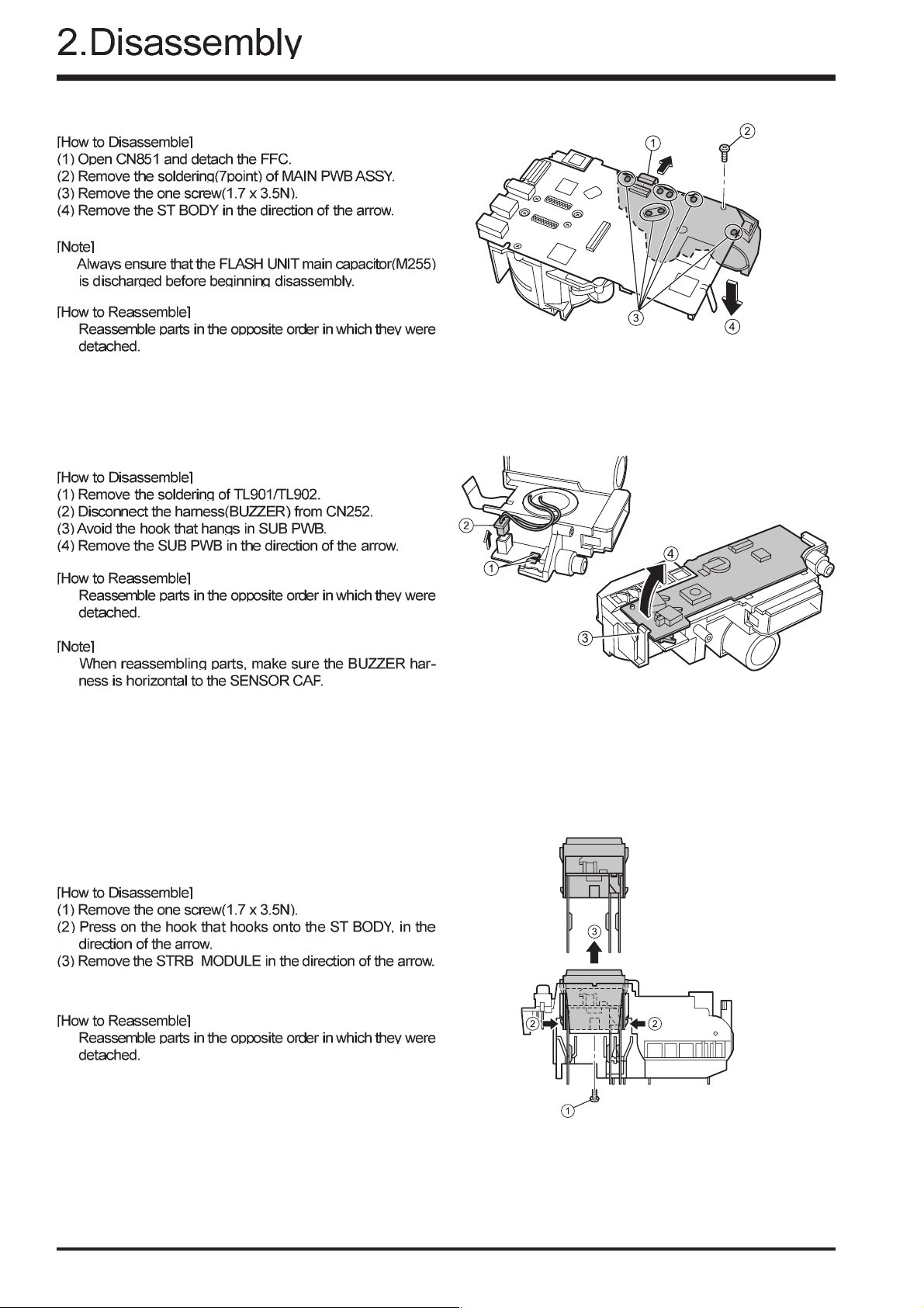
2-11.How to Disassemble the ST BODY
2-12.How to Disassemble the SUB PWB
FinePix A210 Service Manual
2-13.How to Disassemble the STRB_MODULE
14
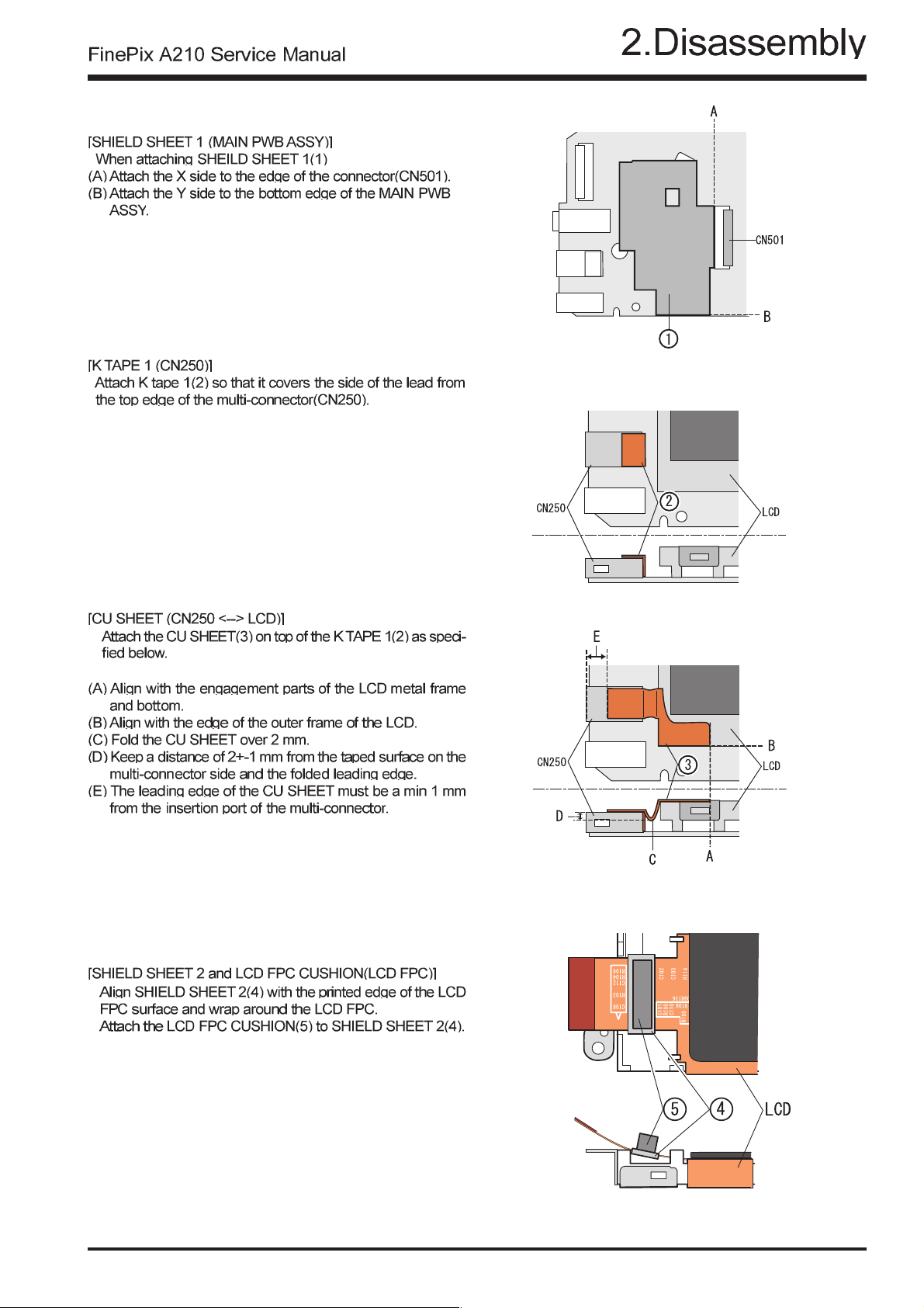
2-14.Location of Sheet Parts
[Note]
Do not use the removed "
Use surely new parts at the time of reassembly.
[Note]
Do not use the removed "K T APE 1 ".
Use surely new parts at the time of reassembly.
SHIELD SHEET 1".
[Note]
Do not use the removed "
Use surely new parts at the time of reassembly.
[Note]
Do not use the removed "
Use surely new parts at the time of reassembly.
CU SHEET ".
SHIELD SHEET 2" .
15
3.Schematics
FinePix A210 Service Manual
3.Circuit Diagrams
3-1.Cautions
Precautions in parts replacement
Do not reuse detached electronic components. Use only new components.
The negative side of tantalum capacitors is weak against heat. Handle with care.
With the exception of Chemical capacitor and tantalum capacitors, the volt age of capacitors of a 50V or lower withstand voltage
is not labeled.
Unless specified, electronic component resistance is 1/16W.
K = 1000 , M = 1000 K
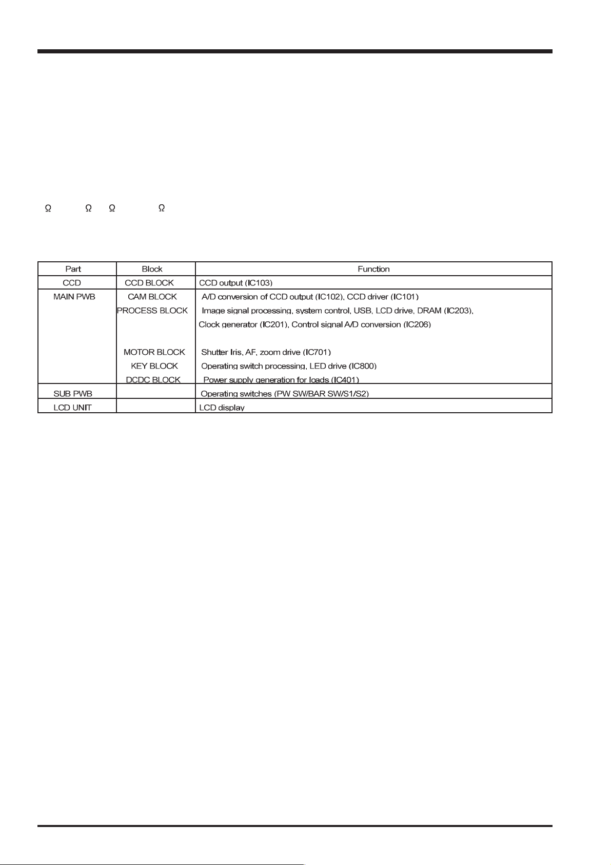
3.2 Names and Functions of Basic Blocks
16

3.Schematics
3-3.Explanation of Functions of Important Blocks
3-3-1.Technical Overview
The FinePix A210 incorporates a 1/2.7 -inch square pixel, primary color interline CCD of 3.34 million pixels(total).
An [xD picture card] is adopted as the recording media.
The optical system employs a newly designed 1-stage retracting barrel 3x zoom lens.
New ICs are the [ACS2 (IC102)] for CCD processing, [KEY IC (IC800)] that incorporates power supply management capabilities into opera-
tion system processing, and system LSI [XCS (IC203)] that pakeged signal processing, LCD drive, TG functions and DRAM.
The flash light block is modularized.
THE camera in internally capable of discharge function of rechargeable battery (NH-10) .
THE camera in internally capable of charge function of rechargeable battery (NH-10) . when used the Picture Cradle CP-FXA10.
The camera incorporates a thermistor to monitor environment temperature (LENS UNIT) and temperature during internal charging the
battrry(NH-10) for safty.
3-3-2.Explanation of Functions of Individual Blocks
(1) CCD Signal Processing/Picture-taking Blocks (CCD BLOCK and CAM BLOCK)
The analog signals output by the CCD (1/2.7 square pixel, primary color interline CCD of 3.34 million pixels[total] [IC103]) undergo color
compensation, adaptive interpolation, amplification (ACG) and signal mixing in the [ACS2 (IC102)] CCD signal processing IC. After that, the
signals are converted into 12-bit digital signals and sent to the [XCS (IC203)] system LSI.
This block has a vertical drive IC (IC101) for driving the CCD.
(2) Motor Block (MOTOR BLOCK)
Upon receiving commands from operating switches, the [XCS (IC203)] signal processing LSI manages the motor drive IC (IC701) so as to
control the motors for AF, shutter, zoom and iris.
(3) Image Signal Processing Block (PROCESS BLOCK)
Input Data from the CCD
The 10-bit digital image data (equivalent to 1H) output by the image unit (CCD/CAM BLOCK) is sent to the [XCS (IC203)] system LSI. It is
here converted into 32-bit (16-bit x 2) data by the internal buffer of the LSI, and image data of 2048 x 1536 pix per frame is temporarily stored
in the [internal DRAM (128 Mbyte)] of the LSI.
Also, the 32-bit image data input to this LSI is used for calculations by the [auto calculation unit] and sent to the [ACS2 (IC102)] CCD
processing IC of the CAM BLOCK so as to obtain a suitable AE, AWB and AF.
Recording Processing to the xD Card
The image data stored in the [internal DRAM (128 Mbyte)] of the [XCS (IC203)] system LSI is sent to the signal processing block one line at
a time where it undergoes unpack processing (32-bit >> 10-bit conversion, processing required prior to digital clamping, ( compensation, 10bit >> 8-bit R/G/B conversion) and YC processing (8-bit digital R/G/B signal >> Y:Cb:Cr = 4:2:2). The 8-bit Y/Cb/Cr data is then sent to the
[internal buffer]. In the [internal buffer], data is arranged in a format that is easy to convert the 8-bit Y/Cb/Cr data into DCT. After going through
the [JPEG calculation unit] and the [media controller], it is recorded on the xD card.
Image Reproduction from the xD Card
The compressed image data from the xD card is sent to the [XCS (IC203)] system LSI as 8-bit image data. It is then sent to the [media control
unit] >> [DRAM unit] >> [internal DRAM (16 Mbyte)] >> [media controller] >> [JPEG calculation unit] >> [signal processing unit]. The [signal
processing unit] does the post-processing of converting the 8-bit Y/Cb/Cr signals into 8-bit R/G/B signals. At the same time, it weighs the text
display signal and displays the text on the LCD UNIT via the [LCD controller].
Picture-taking system adjustment data is stored in the FLASH ROM (IC204).
(4) LCD UNIT
The digital signal sent from the [XCS (IC203)] system LSI is sent to the drive IC of the LCD UNIT via the processing unit on the LCD FPC of
the LCD UNIT, where [LCD drive] and [LCD panel tonal control] are performed.
(5) Power Supply Block (DCDC BLOCK)
The power supply block is built around the DC IC (IC401). It generates the below power supplies and supplies them to the individual blocks.
3.3 V [XCS (IC203), ACS2 (IC102), V-Drv (IC101), EVR (IC206), FLASH ROM (IC204), STRB IC (IC600), MOTOR Drv (IC701),
KEY IC (IC800), xD Picture Card, MAIN PWB, SUB PWB]
EV3 [MAIN PWB, SUB PWB]
A3.3V [XCS (IC203), VIDEO Drv (IC300), CLK GEN (IC201), MAIN PWB, LCD]
STRB 5V [STRB IC (IC600)]
15 V [CCD (IC103), V Drv (IC101)]
-7.5 C [CCD (IC103), V Drv (IC101)]
UNREG [STRB IC (IC600)]
17

3.Schematics
3-4.Block Diagram
FinePix A210 Service Manual
18
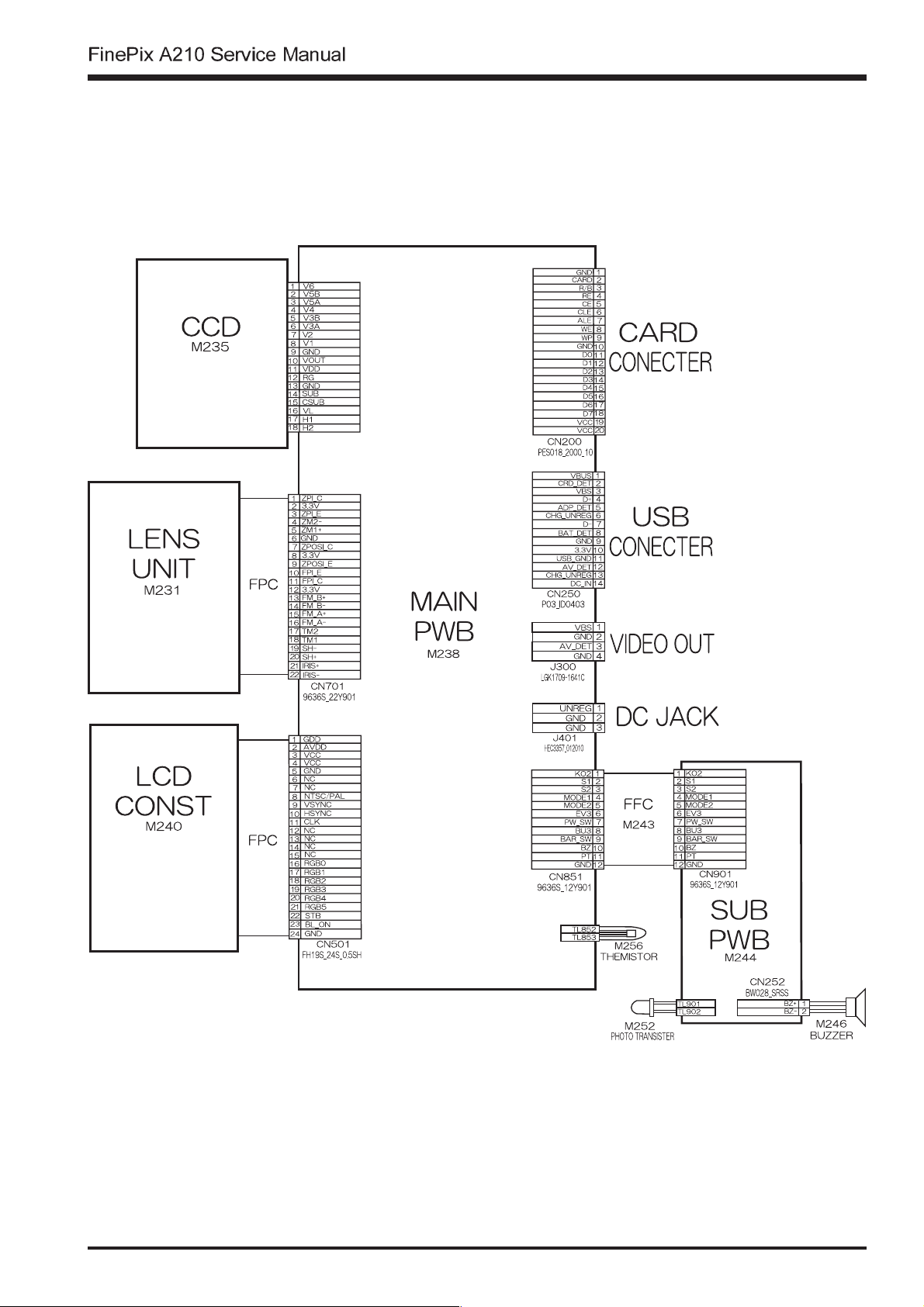
3-5.Overall
3.Schematics
19
3.Schematics
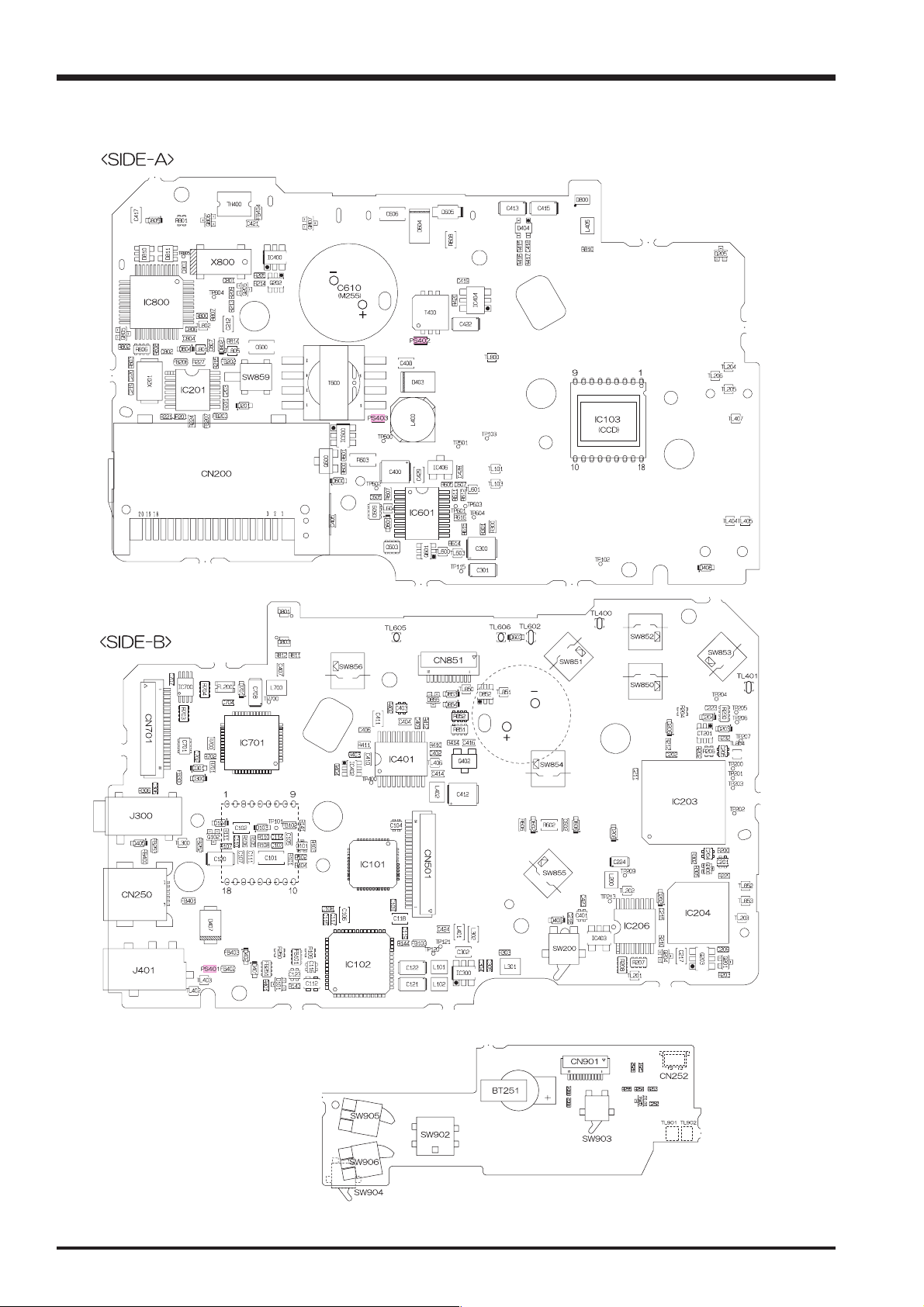
3-6.Mounted Parts Diagrams
3-6-1.MAIN PWB ASSY Component Locations
FinePix A210 Service Manual
3-6-2.SUB PWB ASSY Component Locations
20
 Loading...