

FUJIFILM FinePix A203 Service Manual
DIGITAL CAMERA
FinePix A203
SERVICE MANUAL
US/EU/EG/CA/GE/AS-Model
WARNING
THE COMPORNENTS IDENTIFIED BY THE MARK “ ” ON THE SCHEMATHIC
DIAGRAM AND IN THE PARTS LIST ARE CRITICAL FOR SAFETY.
PLEASE REPLACE ONLY BY THE COMPONENTS SPECIFIED ON THE SCHEMATHIC
DIAGRAM AND IN THE PARTS LIST.
IF YOU USE WITH PART NUMBER UN-SPECIFIED, IT MAY RESULT IN A FIRE AND AN
ELECTORICAL SHOCK.
Ref.No.:ZM00452-102
FUJI PHOTO FILM CO.,LTD.
Printed in Japan 2003.02(S.S.)

SAFETY CHECK-OUT
After correcting the original problem, perform the following safety
check before return the product to the costomer.
FinePix A203 Service Manual
1. Check the area of your repair for unsoldered or poorly
sol dered connections. Check the entire board sur
face for solder splasher and bridges.
2. Check the interboard wiring to ensure that no wires
are pinched or contact high-wattage resistors.
3. Look for unauthorized replacement parts, particu
larly tran sistors, that were installed during a previ
ous repair. Point them out to the customer and rec
ommend their replacement.
4. Look for parts which, though functioning, show obvi
ous signs of deterioration. Point them out to the cus
tomer and recommend their replacement.
5. Check the B + voltage to see it is at the values specified.
6. Make leakage - current measurements to determine
that exposed parts are acceptably insulated from the
supply circuit before returning the product to the customer.
7. CAUTION: FOR CONTINUED
PROTECTION AGAINST FIRE
HAZARD, REPLACE ONLY WITH
SAME TYPE 2.5 AMPERES 125V
FUSE.
2.5A125V
RISK OF FIREREPLACE FUSE
AS MARKED
WARNING!
HIGH VOLTAGE
ATTENTION: AFIN D'ASSURER
UNE PROTECTION
PERMANENTE CONTRE LES
RISQUES D'INCENDIE,
REMPLACER UNIQUEMENT
PAR UN FUSIBLE DE MEME,
TYPE 2.5 AMPERES, 125
VOLTS.
WARNING:
TO REDUCE THE ELECTRIC
SHOCK, BE CAREFUL TO
TOUCH THE PARTS.
2.5A125V
8.

FinePix A203 Service Manual
TABLE OF CONTENTS
TABLE OF CONTENTS
1.General
1-1. Product specification ........................................................ 4
1-2.Names of External Components ......................................7
2. Disassembly
2-1. Internal Components ........................................................8
2-2. Removing the R PANEL ASSY ....................................... 9
2-3. Removing the LCD UNIT............................................... 10
2-4. Removing the MAIN PWB ASSY ................................. 10
2-5. Removing the BATTERY LID ....................................... 11
2-6. Removing the CABINET INNER .................................. 11
2-7. Removing the BARRIER MOTOR ASSY .................... 12
2-8. Removing the FLASH UNIT .......................................... 12
2-9. Removing the LENS UNIT ............................................ 13
3. Schematics
3-1. Cautions .......................................................................... 14
3-2. Basic Block Names and Functions .............................. 14
3-3. Block Diagram ................................................................ 15
3-4. MAIN PWB ASSY Mounting Diagram ......................... 16
3-5. SUB PWB ASSY Mounting Diagram ........................... 16
5. Inspection
5-1. Required Measuring Equipment ................................... 45
5-2. Connection of Measuring Equipment .......................... 45
5-3. Inspection and Factory Settings .................................. 45
6.Parts List
6-1.Packing and Accessories ............................................... 47
6-1-1.For US model ........................................................... 47
6-1-2.For EU model ........................................................... 48
6-1-3.For EG model ........................................................... 49
6-1-4.For CA model ........................................................... 50
6-1-5.For GE model ........................................................... 51
6-1-6.For AS model ............................................................ 52
6-2.Cabinet F block (US/EU/EG/CA/GE/AS model) ......... 53
6-3.Cabinet R block (US/EU/EG/CA/GE/AS model) ......... 54
6-4.Electrical Parts (US/EU/EG/CA/GE/AS model) .......... 55
7. Appendix
7-1.List of Related Technical Updates Issued ................... 56
4. Adjustments
4-1. Adjustment Procedure of Parts Replacement ........... 17
4-2. Measuring Devices......................................................... 17
4-3. Jigs ................................................................................... 17
4-4. Jig Connections.............................................................. 18
4-5. Environment Setup ........................................................ 18
4-6. Installing the Jig Drivers on the PC ............................. 19
4-7. Installing and Starting the Adjustment Software ....... 20
4-8. Initializing the Adjustment Software ............................ 20
4-9. Starting the Adjustment Software ................................ 23
4-10. [F6] : AF adjustment .................................................... 26
4-11. [F4] : CCD data input .................................................. 28
4-12. [F5] : Camera adjustment ........................................... 30
4-13. [F1] : Battery voltage adjustment .............................. 33
4-14. [F3] : LCD Adjustment................................................. 36
4-15. [F7] : Flash adjustment ............................................... 37
4-16. [F8] : Firmware Download ........................................... 39
4-17. [F12] : End Setting ....................................................... 41
3

1.General
FinePix A203 Service Manual
1.General
1-1. Product specification
System
Model Digital Camera FinePix A203
Number of effective pixels
CCD sensor 1/2.7-inch square pixel CCD with RGB Filter
Number of recorded pixels
Storage media xD-Picture Card (16MB to 128MB)
File format Still image: JPEG (Exif Ver.2.2), DPOF-compatible
Viewfinder Real image optical; Frame coverag: 80%
Lens Fujinon 3× optical zoom lens
Aperture F2.8-F4.8/F7.0-F11.6 (automatically selected)
Focus distance f=5.7-17.1 mm (equivalent to 38 mm on a 114mm camera)
Exposure control 64 zones TTL metering, Program AE
Sensitivity Equivalent to ISO 100
White balance Auto (7 positions selectable in Manual mode)
Focal range Normal: Approx. 60 cm/2.0 ft. to infinity
Shutter speeds Variable-speed, 1/2 sec. to 1/2000 sec. (combined with mechanical shutter)
Flash (Auto flash using
flash control sensor)
LCD monitor 1.5-inches, 60,000-pixels TFT
Self-Timer 10 sec. timer clock
2.0 million pixels
Number of total pixels: 2.11 million pixels
1600 × 1200 pixels (1.92 million pixels)/1280 × 960 pixels/640 × 480 pixels
Movie: AVI format, Motion JPEG
*Design rule for Camera File system Compliant
f=38-114 mm on a 35 mm camera
(exposure compensation available in Manual mode)
Macro: Approx. 10 cm-80 cm/3.9 in.-2.6 ft.
Effective range:
Wide-angle: Approx. 30 cm-3.5 m (1.0 ft. -11.5 ft.)
Telephoto-angle: Approx. 60 cm-3.0 m (2.0 ft. -9.8 ft.)
Flash modes: Auto, Red-Eye Reduction, Forced Flash, Suppressed Flash, Slow
Synchro
l
Standard number of available shots/recording time per xD-Picture Card
Quality Mode
Number of recorded pixels
Image Data Size
DPC-16 (16 MB)
DPC-32 (32 MB)
DPC-64 (64 MB)
DPC-128 (128 MB)
2M F 2M N
1600 ´1200 1280 ´960 640 ´480 320 ´240 160 ´120
Approx. 620 KB Approx. 390 KB
25 39
50 79
101
204
159
319
1M 0.3M
Approx. 320 KB
49
99
198
398
Approx. 130 KB
122
247
497
997
Input/Output Terminals
(USB) socket USB (1) for image data output with a personal computer
DC IN 3V (Power input)
Socket for specified AC power adapter (optional)
socket
Power Supply and Others
Power supply Use one of the following:
2AA-size alkaline batteries
2AA-size Ni-MH (nickel-metal hydride) batteries (optional)
AC Power Adapter AC-3V (optional)
4
(Movie)
Approx. 94 sec.
Approx. 191 sec.
Approx. 6.4 min.
Approx. 12.9 min.
(Movie)
Approx. 5 min.
Approx. 10.1 min.
Approx. 20.2 min.
Approx. 40.6 min.

FinePix A203 Service Manual
1.General
No. of available shots
using battery
(battery life)
Battery type
Alkaline batteries
Ni-MH batteries
HR-3UF 1700 mAh
(Condition: Power saving mode ON, with fully charged battery (Ni-MH))
With LCD monitor
ON
Approx. 200 frames
Approx. 300 frames
With LCD monitor
OFF
Approx. 300 frames
**
Approx. 400 frames
This indicates the number of available frames shot consecutively at room temperature with a flash use rate of 50%. Note that these figures may vary depending
on the ambient temperature and the amount of charge in the battery. The number
of available shots or available shooting time will be lower in cold conditions.
Conditions for use Temperature: 0
o
C to +40oC (+32oF to +104oF); 80% humidity or less (no conden-
sation)
Camera dimensions 97.0 mm × 63.9 mm × 34.3 mm/3.8 in. × 2.5 in. × 1.4 in.
(W/H/D) (not including accessories and attachments)
Camera mass (weight)
Weight for photography
Approx. 145 g/5.1 oz. (not including accessories, batteries or xD-Picture Card)
Approx. 200 g/7.1 oz. (including batteries and xD-Picture Card)
Accessories l 16 MB, xD-Picture Card (1)
Supplied with: Anti-static case (1)
l LR6 AA-size alkaline Batteries (2)
l Hand strap (1)
l Interface Set (1)
CD-ROM: Software for FinePix SX (1)
Special USB cable with Noise Suppression core (1)
l Owners Manual (1)
Optional Accessories l xD-Picture Card
DPC-16 (16MB)/DPC-32 (32MB)/DPC-64 (64MB)/DPC-128 (128MB)
l AC Power Adapter AC-3V
l Fujifilm Rechargeable Battery 2HR-3UF
l Fujifilm Battery charger with Battery BK-NH (With Euro type or UK type plug)
l SC-FXA01
l DPC-R1 Image Memory Card Reader
Compatible with Windows 98/98 SE, Windows Me, Windows 2000 Profes
sional, Windows XP or iMac, Mac OS 8.6 to 9.2, Mac OS X (10.1.2 to
10.1.5) and models that support USB as standard.
Compatible with SmartMedia of 3.3V, 4MB to 128MB.
l DPC-AD PC Card Adapter
Compatible with SmartMedia of 3.3V, 2MB to 128MB.
5

1.General
FinePix A203 Service Manual
Explanation of Terms
DPOF: Digital Print Order Format
DPOF is a format used for recording information on a storage media (image
memory card, etc.) that allows you to specify which of the frames shot using a
digital camera are printed and how many prints are made of each image.
EV: A number that denotes exposure. The EV is determined by the brightness of the
subject and sensitivity (speed) of the film or CCD. The number is larger for bright
subjects and smaller for dark subjects. As the brightness of the subject changes, a
digital camera maintains the amount of light hitting the CCD at a constant level by
adjusting the aperture and shutter speed. When the amount of light striking the
CCD doubles, the EV increases by 1. Likewise, when the light is halved, the EV
decreases by 1.
JPEG: Joint Photographics Experts Group
A file format used for compressing and saving color images. The compression
ratio can be selected, but the higher the compression ratio, the poorer the quality
of the expanded image.
Motion JPEG: A type of AVI (Audio Video Interleave) file format that handles images and sound
as a single file. Images in the file are recorded in JPEG format. Motion JPEG can
be played back by QuickTime 3.0 or later.
PC Card: A generic term for cards that meet the PC Card Standard.
PC Card Standard: A standard for PC cards determined by the PCMCIA.
PCMCIA: Personal Computer Memory Card International Association (US).
White Balance: Whatever the kind of the light, the human eye adapts to it so that a white object still
looks white. On the other hand, devices such as digital cameras see a white sub-
ject as white by first adjusting the color balance to suit the color of the ambient
light around the subject. This adjustment is called matching the white balance. A
function that automatically matches the white balance is called an Automatic
White Balance function.
6

FinePix A203 Service Manual
1-2.Names of External Components
1.General
Shutter button
Flash
Lens/Lens cover
POWER switch
Flash control sensor
Self-timer lamp
Viewfinder window
(USB) socket
DC IN 3V
(Power input)
socket
BACK button
Viewfinder
Viewfinder lamp
DISP button
LCD monitor
Flash button
Tripod mount
Battery cover
MENU/OK button
Mode dial
button
( Zoom in)
( Zoom out) button
Strap mount
Battery compartment
xD-Picture Card slot
7

2. Disassembly
2. Disassembly
2-1. Internal Components
FinePix A203 Service Manual
CABINET REAR ASSY
SUB PWB ASSY
FLASH UNIT
BATTERY HOLDER
LCD UNIT
MAIN PWB ASSY
LENS UNIT
BARRIER MOTOR UNIT
CABINET FRONT ASSY
8

FinePix A203 Service Manual
2-2. Removing the R PANEL ASSY
[Disassembly]
1. Remove the three M1.7x5 screws.
2. Open the battery cover.
3. Raise the R PANEL ASSY in the direction of the
arrow.
Note:
Always ensure that the FLASH ASSY main condenser is
discharged before beginning disassembly.
Discharge point
2. Disassembly
1
3
1
[Assembly]
Set the mode dial to the camera position and assemble it.
Assemble in the reverse order to disassembly.
1
2
9

2. Disassembly
2-3. Removing the LCD UNIT
FinePix A203 Service Manual
[Disassembly]
1. Remove the M1.7x5 screws.
2. Raise the LCD UNIT in the direction of the arrow.
3. Remove the connector.
3
2
1
[Assembly]
Assemble in the reverse order to disassembly.
2-4. Removing the MAIN PWB ASSY
[Disassembly]
1. Remove the FFC.
2. Remove the NAIN PWB in the direction of the arrow
taking care not caught of the shutter button.
2
1
10
[Assembly]
Assemble in the reverse order to disassembly.

FinePix A203 Service Manual
2-5. Removing the BATTERY LID
[Disassembly]
1. Remove the M1.7x5 screw.
2. Remove the BATTERY HOLDER in the direction of
the arrow.
3. Remove the BATTERY SHAFT.
3
2. Disassembly
1
2
[Assembly]
Assemble in the reverse order to disassembly.
2-6. Removing the CABINET INNER
[Disassembly]
1. Remove the three M1.7x3.5 screws.
2. Remove the CABINET INNER in the direction of the
arrow.
[Assembly]
Set the barrier assy to the flute and put it.
1
2
Match and build the pin of barrier lever and barrier
assy.
11
2. Disassembly
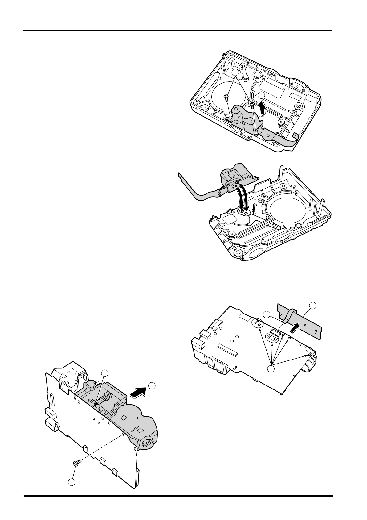
2-7. Removing the BARRIER MOTOR ASSY
[Disassembly]
1. Remove the two M1.7x3.5 screws.
2. Remove the BARRIER MOTOR ASSY in the direction of the arrow.
[Assembly]
Match and assemble the hole of the barrier lever.
FinePix A203 Service Manual
1
2
2-8. Removing the FLASH UNIT
[Disassembly]
1. Remove FFC
2. Remove SUB PWB ASSY.
3. Remove the six soldered points.
4. Remove the trigger coil soldered poiint.
5. Remove one screw (M1.7x5.0).
6. Remove in the direction of the arrow.
4
2
1
3
6
12
[Assembly]
Assemble in the reverse order to disassembly.
5

FinePix A203 Service Manual
2-9. Removing the LENS UNIT
[Disassembly]
1. Remove two screws (M1.7x2.5).
2. Remove the CCD soldered points.
3. Remove FFC
4. Remove the LENS UNIT in the direction of the
arrow.
2. Disassembly
4
2
3
1
[Assembly]
Assemble in the reverse order to disassembly.
13

3. Schematics
FinePix A203 Service Manual
3. Schematics
3-1. Cautions
<Cautions when replacing parts>
Do not reuse removed parts. Always use new parts.
Note that the -ve side of tantalum condensers is readily damaged by heat.
Except for chemical condensers and tantalum condensers, voltage is not displayed on condensers with a voltage
resistance of 50V or less.
Resistors not marked are 1/16W chip resistors.
KW = 1000Ω, MW = 1000KΩ
B characteristics of variable resistors and semi-fixed resistors are not displayed.
3-2. Basic Block Names and Functions
Part name Block name Function
LENS CONST CCD BLOCK CCD output
MAIN PWB ASSY CAM BLOCK CCD output A/D conversion (IC103)
CCD driver ( IC102)
PROCESS BLOCK Image signal processing, USB communications,
system control (IC304)
MOTOR BLOCK Shutter/iris/AF/zoom drive (IC703)
POWER ON BLOCK Power supply management (IC301)
LCD BLOCK LCD control (IC304)
DC/DC BLOCK Power supply generation (IC401,IC403)
CHG BLOCK Li battery charging control (IC654)
STRB BLOCK Strobe charging control (IC602)
SUB PWB ASSY RSW BLOCK Power SW,Shutter SW,Backup battery
FLASH UNIT FLASH BLOCK Flash
14

FinePix A203 Service Manual
3-3. Block Diagram
3. Schematics
DR_SW
3.3V
LCD BLK
LCD_BR
LCD_CONT
LCD
from EVR
LCDCLK
LCDVD
LCDHD
IC304 FF4146 WCS_MCM
48.00MHz
OSC
WCS
LCD
IBUF
AU
A015AN02
LCDDATA
[7:2]
MEDIA
BL LED
xD-Picture Card
CPU Core
JPEG
Serial
SEL
Memory
CS
SIO1
Control
FLASH ROM
1MByte
Local
BUS
Memory
Control
USB
TRON
D+, D-, VBUS,
USB
TIMER
DRAM
64MBit x 16
FLASH BLK
STRB_DIS
STRB_COK
STRB_SY
IC305
SAMSUNG
NEC
IC602
CTL IC
STRB_CC
STRB_FULL
K4S641632E_TL
UPC5023GR_178_8J
GSEL, V_TH, STRB_CHG
from EVR
24.545MHz
CAMCLK
PRO BLK
SCS3A
CAM BLOCK
CCD OUT
IC101
CCD
L
O
LENS
x3 ZOOM
LENS
CCD DATA [9:0]
MN39473PJ-F
MATSUSHITA
F
P
Barrier
HI, VI, ADCLK,FI
O CONT, VRESET
IC103
ANALOG
DEVICES
V Drv
CCDLD
SI, SO, SCLK
TG_SY
AD80038JBC
IC102
FFM MD2171B
IRIS1, IRIS2,
SHUT1,SHUT2
Motor Drive
BAT_V
VDET
IC301
S-6404A
PWR MANAGEMENT IC
FMA1, FMA2, FMB1, FMB2
IC703
SANYO
LB8649FN
RTC
CISC
FOCUS_HP
Z_HP, Z_PLS
BAR1,BAR2
TELE, WIDE
BAR_OPEN
4.19MHz OSC
32.768KHz Xtal
SIO
IC303
EVR 3ch
BH2220FVM
ZMPS
STRB_CHG
GSEL, V_TH
to FLASH
SIO2
EVR_LD
IC302
M62368GP
EVR 6ch
LCD_CONT
LCD_BR_UNI,
IRIS_SPD, FMPS
to LCD
to MOTOR Drive
BL_ON
CAM_ON
IC401
DC/DC IC 2ch
DC BLOCK
KEY1, KEY2, MODE
PWR_SW, S1/S2
LCD_ON
FA7715J
CARD_ON
MOTOR_ON
F_LON
YUSABURION
IC403
DC/DC IC 3.4V
Z_LON
S-8340A34AFT
Buzzer
ST
LED
B
LED
R
LED
15

3. Schematics
3-4. MAIN PWB ASSY Mounting Diagram
<Side A>
25
25
25
FinePix A203 Service Manual
<Side B>
CN801
SW802
CN701
J401
CN302
F401
25
SW804
CN501
SW803
3-5. SUB PWB ASSY Mounting Diagram
SW809
SW801
SW805
SW806
SW301
SW808
SW807
SW810
CN702
16
SW902
CN901
SW901

FinePix A203 Service Manual
4. Adjustments
4. Adjustments
4-1. Adjustment Procedure of Parts Replacement
Adjust in the order noted below after replacing the parts in the table.
CAM AF CCD difect LCD Battery Flash End setting
LENS ASSY 1 2 3 4 5 6 7*
MAIN PWB ASSY 1 2 3 4 5 6 7*
FLASH UNIT 12*
*: If End setting is not run the camera will remain in the jig mode, and will not enter the storage mode when connected
to the PC. Always run End setting after completing adjustments.
4-2. Measuring Devices
Measuring device Remarks
Regurated power supply For adjustment.
Pattern box PTB450 or equivalent.
Waveform monitor For function inspection.
Vector scope For function inspection.
Digital voltmeter For adjustment.
PC For various adjustments and operation checks (PC-AT compatible, Windows 98).
Luminance meter LS-110 (Minolta) or equivalent.
Color thermometer Color Meter III (Minolta) or equivalent.
TV monitor NTSC_TV monitor, 600 or more lines resolution (for function inspection)
Flash meter For function inspection.
4-3. Jigs
Jig Part number Application
Filter LB140 ZJ00006-100 CAM adjustment (common to DS-7/20/30)
Siemens star chart ZJ00251-100 AF adjustment (common to FinePix 6800Z)
Conversion lens (f = 600mm) ZJ00007-100 AF adjustment (common to 8mm VTR, FinePix 500)
Lens holder ZJ00008-100 AF adjustment (common to 8mm VTR, FinePix 500)
Stand ZJ00009-100 AF adjustment (common to 8mm VTR, FinePix 500)
Base plate ZJ00010-100 AF adjustment (common to 8mm VTR, FinePix 500)
Grey chart (reflective) ZJ00254-100 Strobe adjustment (common to FinePix 700)
USB cable FZ04205-100 PC adjustment
Power supply cable jig ZJ00214-100
FinePix A203_U/E adjustment software
FinePix A203 CCD Data Vol.1
AC adapter (AC-3V) For general adjustment.
DSC jig driver ZJ00476-100 DSC jig driver setup.
Discharger ZJ00581-100 Discharge for FLASH UNIT
LCD adjustment jig ZJ00585-100 LCD adjustment.
LCD adjustment card ZJ00579-100 LCD adjustment. *1
ZJ00594-100
ZJ00595-100
General adjustments (common to MX-10, FinePix 4700Z)
Dedicated software for general camera adjustment. *1
Camera adjustment. *1
*1
*1 : Data available from WEB site
17
4. Adjustments
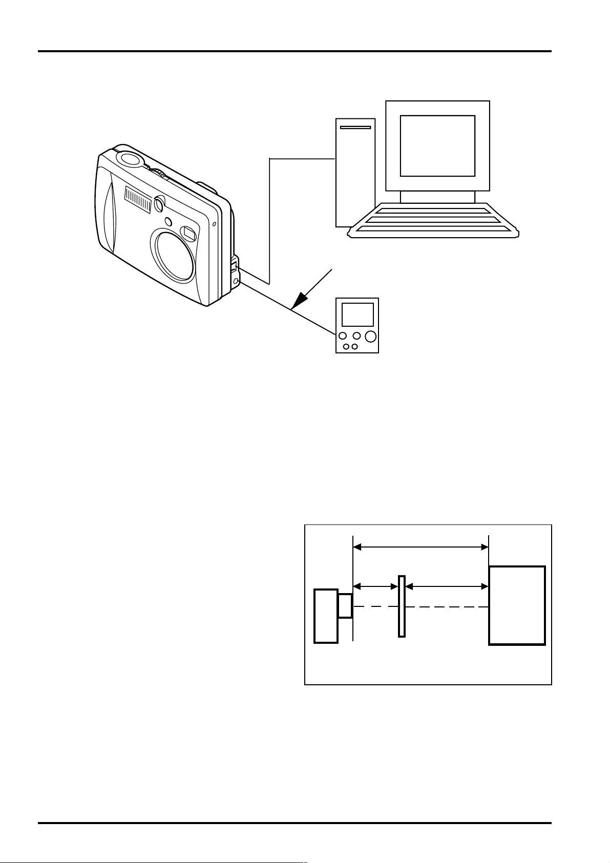
4-4. Jig Connections
FinePix A203 Service Manual
PC
FX-A203
USB cable
Power supply cable jig*
DC-3V
Regurated power supply
* Always measure input voltage close to the DC_IN pin when making adjustments.
os:Windows98
4-5. Environment Setup
(1)Setup for camera adjustment (Fig.A)
<<All white pattern>>
Set the distance between the camera reference face (*1)
and the pattern box to within approximately 50mm.
Filter (LB140) and reference face in direct contact.
1. Color temperature: 6100±50K (with LB140 filter)
Measurement position : middle of pattern box
Measuring device : Minolta Color Meter III F or
equivalent
*Color temperature measurement
Filter (LB140) and pattern box in direct contact
Adjust color temperature of pattern box to 6100±50K
with filter (LB140) in contact with color thermometer.
2. Luminance: 160±5cd/m
Measurement position : middle of pattern box
Measuring device : Minolta Luminance Meter LS-110
or equivalent
*Luminance measurement
Filter (LB140) and pattern box in direct contact
Adjust luminance of pattern box to 160±5cd/m
filter (LB140) in contact with luminance meter.
2
(with LB140 filter)
2
with
Within 80mm
Within
30mm
Camera
<Fig.A> Setup for Camera Adjustment
(*1)Front face of LENS ASSY used as camera reference face.
Filter (LB140)
Within
50mm
Center
Pattern box
18
 Loading...